

Page 1
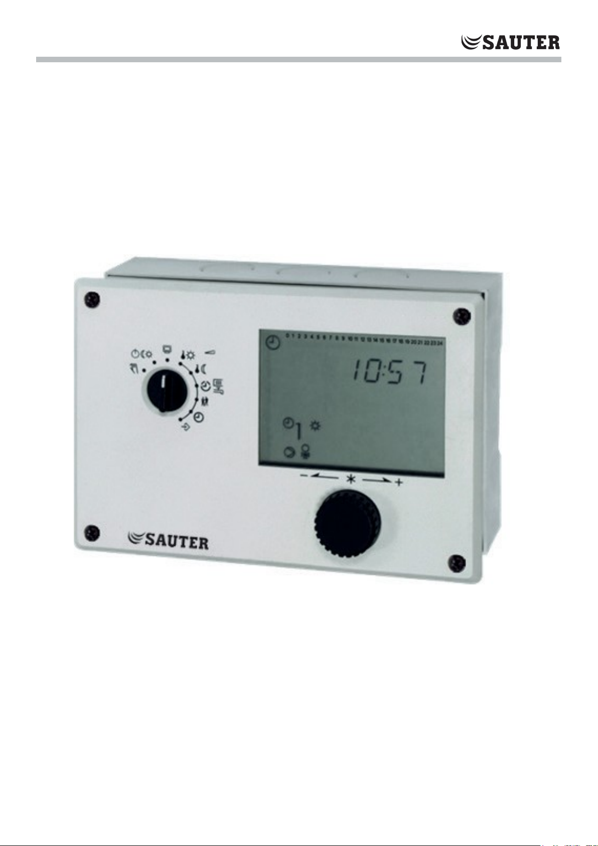
SAUTER equitherm®
Heating and District Heating Controller
EQJW146F001
Short Instruction Manual
Firmwareversion 2.33,
April 2017
Page 2
2
KA_EQJW146F001_EN011
Short Instruction Manual
Warranty
We are constantly developing our products further and therefore reserve the right to make changes to the products at any time without
prior notice.
We assume no liability for the correctness or completeness of these operating instructions. No liability is assumed for the fact that the
buyer can use the products for a certain purpose. Claims of the buyer, in particular claims for damages including loss of profit or other
financial losses are excluded. This does not apply if the cause of damage is based on intent or gross negligence. If an essential contractual
obligation is negligently breached, our liability shall be limited to the foreseeable damage.
Safety Information
The device may only be mounted, started up or operated by trained and experienced personnel familiar with
this product. Proper transport and storage are assumed.
Table of Contents
Installation .........................................................................................................................................................................3
Assembly...........................................................................................................................................................................3
Electrical connection ..........................................................................................................................................................3
Operating controls .............................................................................................................................................................4
Display ..............................................................................................................................................................................5
Information level ................................................................................................................................................................5
Operating modes ...............................................................................................................................................................6
Set operating mode ...........................................................................................................................................................6
Setting the time and date ...................................................................................................................................................6
Check and change times-of-use ........................................................................................................................................7
Check and set party mode .................................................................................................................................................8
Commissioning ..................................................................................................................................................................8
Set system code number ...................................................................................................................................................8
Hydraulic systems .............................................................................................................................................................9
Activating and deactivating functions ............................................................................................................................... 13
Change parameter .......................................................................................................................................................... 14
Setting the factory settings .............................................................................................................................................. 14
Key figures ...................................................................................................................................................................... 14
Manual operation ............................................................................................................................................................. 15
Malfunction - Error list
Function block list ............................................................................................................................................................16
CO1: Heating circuit (HK1) (not system 1.9)* ...................................................................................................................16
CO2: Heating circuit (HK2) (systems 3.x, 4.x and 10.0, 16.6)* .........................................................................................17
CO4: DHW circuit (systems 1.1–1.3, 1.5, 1.6, 1.9, 2.x, 4.1, 4.5, 11.x )* ............................................................................18
CO5: System-wide functions (all systems) .......................................................................................................................19
CO6: Modbus ..................................................................................................................................................................20
CO7: Device bus (all systems, F02, F03, ... only with CO7 -> F01 - 1) 21 ........................................................................21
Parameter list ..................................................................................................................................................................22
PA1: Parameter HK1 (Heating circuit 1) ...........................................................................................................................22
PA2: Parameter HK2 (Heating circuit 2) ...........................................................................................................................22
PA4: DHW circuit parameter ............................................................................................................................................22
PA5: System-wide parameters (all systems) ....................................................................................................................23
PA6: Modbus ...................................................................................................................................................................23
Technical data .................................................................................................................................................................23
Article list ......................................................................................................................................................................... 24
Notes ............................................................................................................................................................................... 24
The device is intended for use in power installations. The relevant safety regulations must be observed during
connection and maintenance.
...................................................................................................................................................... 15
Page 3
3
KA_EQJW146F001_EN011
Short Instruction Manual
The EQJW146F001 controller is used to control a maximum of two control circuits:
•
Control of a primary heat exchanger or boiler. Max. one mixed and one unmixed heating circuit (each weather controlled) as
well as the control of the DHW heating on the secondary side.
•
Control of a weather-compensated heating circuit and DHW heating with two valves on the primary side.
•
Control of two weather-compensated heating circuits with two valves on the primary side.
It has eight temperature sensor inputs, two binary inputs, one 0-10V control output and seven switching outputs.
The controller is ready for operation with the factory-set temperatures and time programs. During commissioning, the current
time and date must be entered on the controller and system-dependent parameters must be defined.
These short instruction manual is intended to provide necessary information during installation and commissioning of the controller.
Further information can be found at http://www.sauter-cumulus.de.
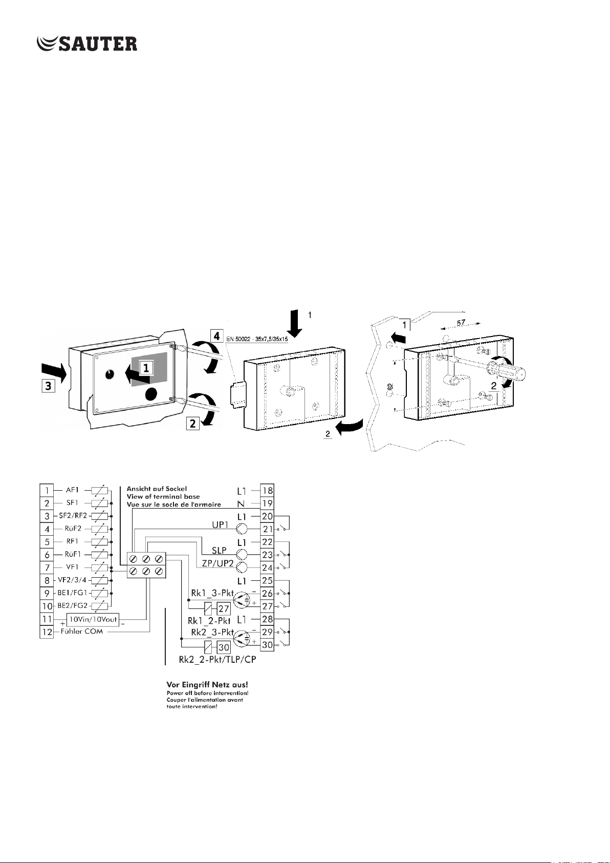
Installation
Assembly
Front panel mounting DIN rail Wall mounting
Electrical connection
This connection diagram is shown on the back of the
controller.
The housing must be opened for the cable connection. For
the cable entry, the marked openings at the top, bottom or rear of the rear
part of the housing must be broken through and provided with the enclosed
choke nipples or suitable cable glands.
Connection of sensors and 0-10V drives
Terminal strips with a cross-section of at least 2 x 0.5 mm² can be
connected to the terminal strips on the rear of the housing.
Connection of 3-point/2-point drives and pumps
Connect cables as damp-proof cables with at least 1.5 mm² to the terminals
of the controller output. It is recommended to check the running direction
of the valve during commissioning
.
Page 4
4
KA_EQJW146F001_EN011
Short Instruction Manual
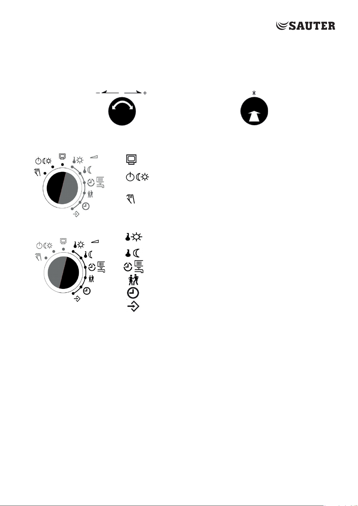
Operating controls
The operating controls are located on the front of the controller.
Rotary pushbutton
Turn: Press:
Display, select parameters and function blocks Confirm adjusted selection or setting
Rotary switch - Operating mode
Information level, rotary switch in normal position
Operating modes
Manual mode:
manual switching of pumps and valves, percentage setting
of the output value
Rotary switch – Parameter
Day set point (rated room temperature)
Night set point (reduced room temperature)
Times-of-use for heating/drinking water heating
Special use/party function
Controller time: Setting the time, date and year
Configuration and parameter level
Page 5
5
KA_EQJW146F001_EN011
Short Instruction Manual
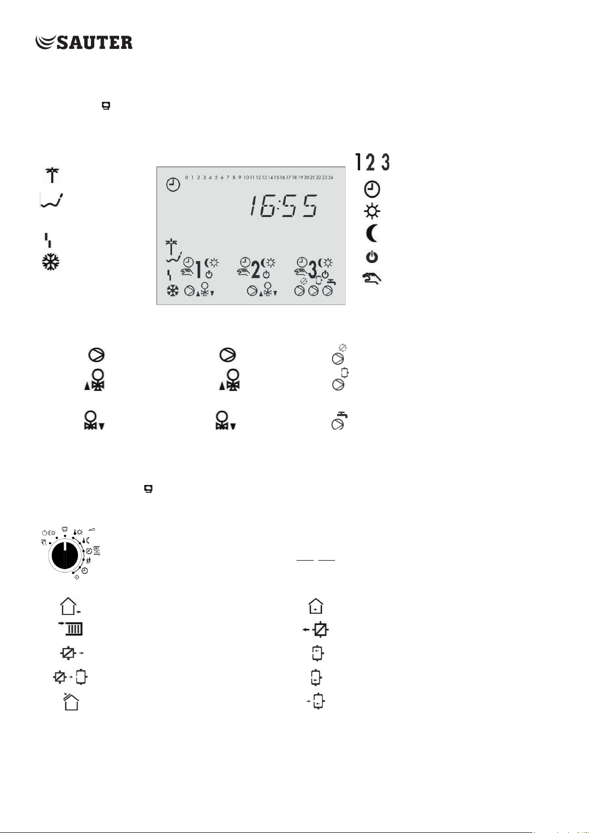
Display
The display indicates the time as well as information about the operation of the controller when the rotary switch is at the
normal position (information level). The times-of-use together with temperatures of the various control circuits can be
viewed on the display by turning the rotary pushbutton. The times-of-use are represented by black squares below the row of
numbers at the top of the display. Icons indicate the operating status of the controller.
Heating circuits
Vacation mode
Automatic mode
Public holiday
Day mode
Operational fault
Frost protection
Heating circuit 1 Heating circuit 2 DHW circuit (3)
Circulation pump UP1 Circulation pump UP2
Valve HK1 opening Valve HK2 opening Storage loading pump
SLP*
Valve HK1 closing Valve HK2 closing Circulation pump ZP*
* UP1, UP2, TLP, CP, SLP and ZP represent the selection display for the pumps in manual mode.
Night mode
Stand-by mode
Pump output TLP/CP*
Manual mode
Information level
At the normal switch position (information level), the time, date, public holidays and vacation periods as well as the
temperatures measured by the connected sensors and their set points can be retrieved and displayed.
Depending on the configuration of the controller, the current values of the following data points are displayed one after the other:
Set the rotary switch to information:
the time is displayed.
:
Time
Outside temperature Room temperature heating circuit 1, 2
Temperature at flow sensor VF,
Heating circuit 1, 2
Temperature at flow sensor VF1,
primary exchanger circuit
Temperature at flow sensor VF2, VF4,
DHW
Temperature at solar sensor VF3
Temperature at return sensor RüF
Temperature at storage sensor SF1
Temperature at storage sensor SF2
Temperature at the storage tank
Page 6
6
KA_EQJW146F001_EN011
Short Instruction Manual
Operating modes
Day mode (rated operation)
Night mode
(reduced
operation)
Regardless of the programmed times-of-use and summer mode, the set points relevant for
rated operation are used by the controller.
Regardless of the programmed times-of-use, the set points relevant for reduced operation
are used by the controller.
Stand-by
mode
Automatic mode During the programmed times-of-use, the controller works in rated operation. Outside
Manual mode
Setting the operating modes
Turn back the rotary switch on normal position (Information level)
Remark: In automatic mode, the current phase of the time program for day mode or night mode is displayed
together with the symbol in the information level.
Regardless of the programmed times-of-use, control operation is deactivated. Only the frost
protection is activated, if need be.
these times-of-use, the controller is in reduced operation, un- less control operation is
deactivated depending on the outdoor temperature. The controller switches automatically
between both operating modes.
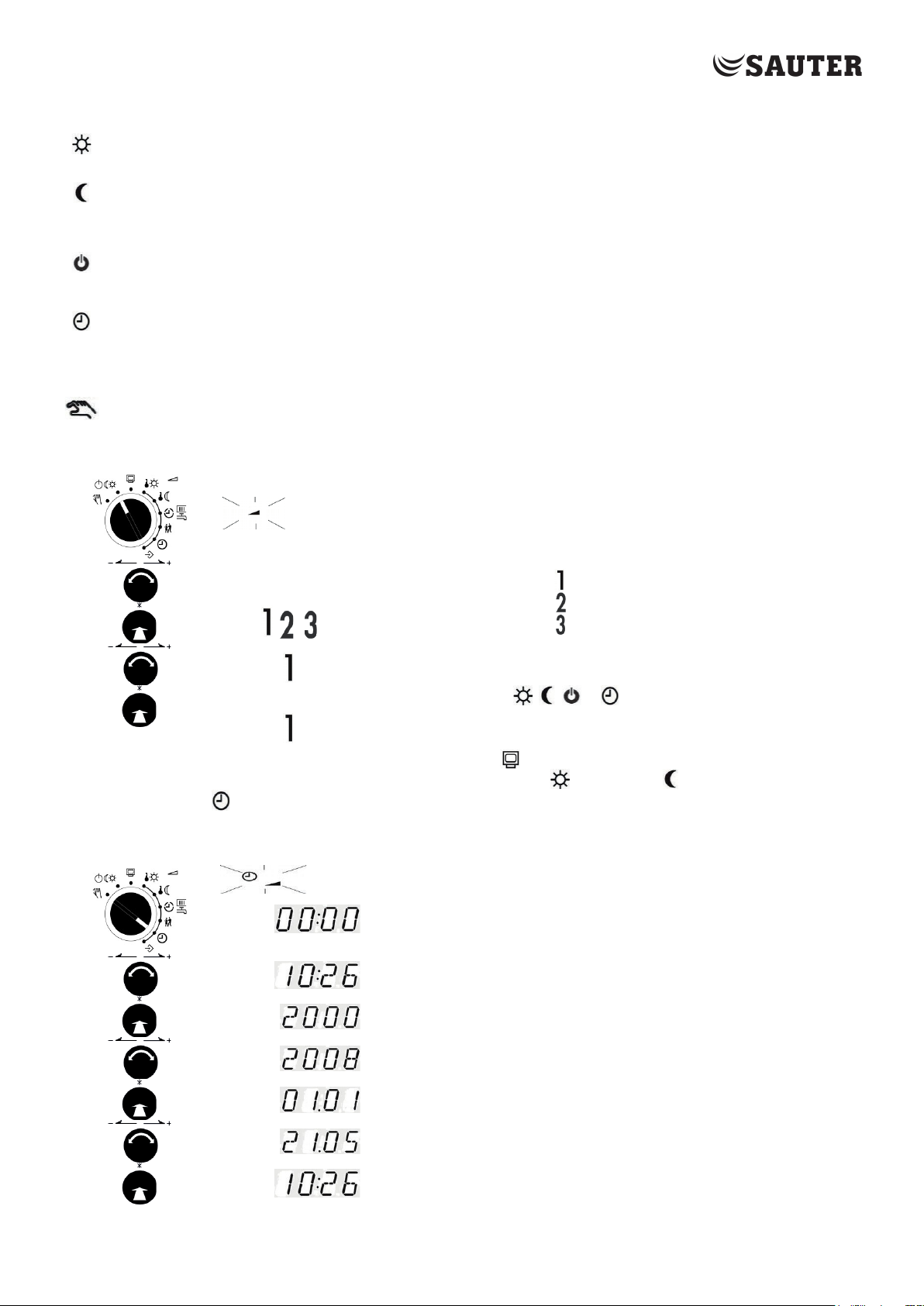
Valves and pumps can be controlled manually
Turn the rotary switch to operating
modes. Parameter symbol flashes
In systems with only one control loop (e.g. Anl 1.0), the steps for
selecting the control loop are not required..
Turn the button;
Select the circuit:
Push the button;
Confirm the circuit
Turn the button;
Select operating mode:
Push the button;
Confirm operating mode
Heating circuit 1
Heating circuit 2
DHW/Circulation pump
, ,
or
Setting time and date
Turn the rotary switch to time;
Time and parameter symbol
flashing, time is displayed
Turn the button; Edit
the controller time
Push button;
Confirm the adjusted time, year is displayed
Turn button;
Edit year
Push button;
Confirm year, date is displayed
Turn button;
Adjust date
Push button; confirm
date, time is displayed
Page 7

7
KA_EQJW146F001_EN011
Short Instruction Manual
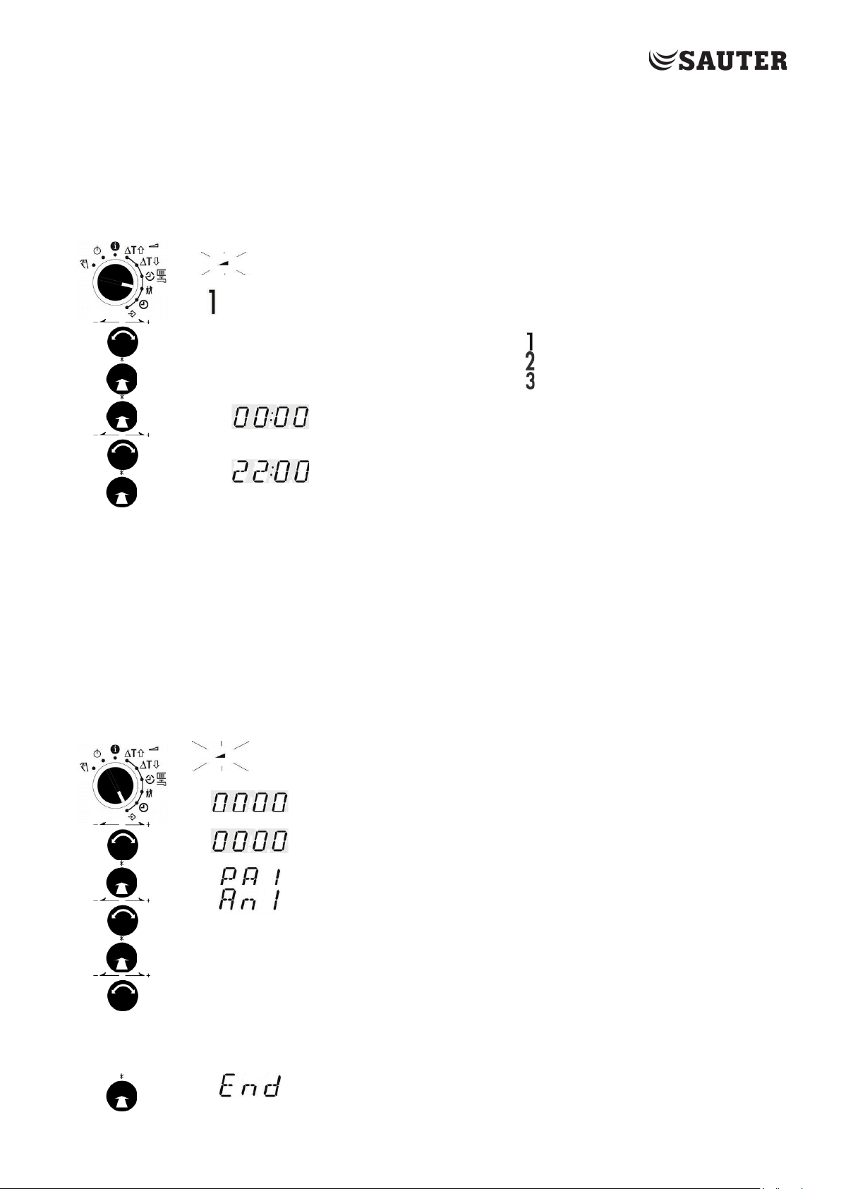
Check and setting the times-of-use
Three times-of-use can be programmed for each day of the week. If only one time-of-use is required, the start and end times
of the second time-of-use must be identical. The third time-of-use is then no longer displayed. If two time-of-use periods are
required, the start and end times of the third time-of-use must be identical.
Set rotary switch to times-of-use;
Time and parameter symbol flashing, heating (1) is displayed
In systems with only one control circuit (e.g. Anl 1.0), the steps for
selecting the control circuit and specifying the DHW circuit are not
required. In systems 1.5 and 1.9, only the DHW circuit is controlled, so the
steps for selecting the control circuit are omitted.
Turn the button;
Select the circuit:
Heating circuit 1
Heating circuit 2
Push the button;
Confirm the circuit
DHW/Circulation pump
Turn the button;
Specify DHW:
Push button;
Confirm specification
DHW
Circulation pump
Push button; Symbol for heating and daily digits are
displayed
Turn button; select day of week (1 = Monday,
2 = Tuesday, ..., 1-7 = daily)
Times-of-use for weekdays are displayed for checking purposes
Press rotary pushbutton; start time for time-of-use is displayed.
Turn button; change start time for time-of-use
Press button; start time is confirmed
S
top time for times-of-uses is displayed
Turn button; Changing the stop time for the time-of-use
Push button; the stop time is confirmed; the times-of-use for the
following day of the week are displayed for checking purposes.
Turn button; 'End' is displayed
Push button
The time-of-use level for the control circuit is exited
Page 8
8
KA_EQJW146F001_EN011
Short Instruction Manual
I.0
I. I
Check and setting party mode
With the Party mode function, the rated operation of the controller (day) - deviating from the set times-of-use - is continued or initiated for
the duration of the set party timer. The party timer starts to run when the rotary switch is turned back to one of the operating mode
positions. After the party timer has expired, the party function resets to 00:00.
Party mode is set for up to 48 hours in 15-minute increments.
Set rotary switch to party mode;
Parameter symbol flashes, heating (1) is displayed
the remaining time of the set party timer. The steps for selecting the control
For systems 1.0, 1.9 and 3.5, the display shows 00:00 or
loop are omitted.
Turn button;
Select control circuit:
Push button;
Confirm control circuit
.
Heating circuit 1
Heating circuit 2
DHW/Circulation pump
Push button
Party timer for control circuit is displayed
Turn button;
Party timer for control circuit is adjusted
Push button; party timer for control circuit is confirmed, control
circuit is displayed
Start-Up
The controller is ready for operation with the factory-set temperatures and time programs. During start-up, the current time
and date must be entered on the controller, the system selected and system-dependent parameters defined.
The changes to the controller configuration and parameterization described in this chapter can only be made after entering
the valid code number for general parameterization and configuration (page 14).
Setting the system code number
A distinction is made between various hydraulic circuit variants. Each system is represented by a system code number. The
systems are shown in the manual. Changing the system code number resets previously set function blocks to the factory
setting (FS). Function block parameters and parameter level settings are retained..
Set rotary switch to parameter and functions;
Symbol Parameter flashes,
Key number is displayed
Turn button
Set valid key number (page 14)
Push button
Parameter level 1
(control circuit 1) is
displayed
Push button
Select display 'Anl
Push button
System code number is displayed
Turn button
Adjust system code
Push button; system code number is confirmed
Factory settings for the selected system are set automatically 'End' is displayed - system
parameters can be modified as follows
Page 9

9
KA_EQJW146F001_EN011
Systems
System 1.0
Short Instruction Manual
Systems 1.1 bis 1.3
System 1.5
System 1.9
System 2.0
System 1.6
Systems 2.1 bis 2.3
Selection of types for DHW heating for systems 1.x and 2.x: Page 12
Page 10

10
KA_EQJW146F001_EN011
Short Instruction Manual
System 11.1
System 3.0
System 3.5
System 4.0
System 4.5
System 4.1
System 10.0
System 11.0
Page 11

11
KA_EQJW146F001_EN011
System 11.2
Short Instruction Manual
System 11.1/11.2 buffer storage
System 11.5
System 11.9
System 11.6
System 16.0
System 16.1
System 16.2
Page 12

12
KA_EQJW146F001_EN011
Short Instruction Manual
System 16.6
System 16.3
System 16.4
Types for DHW heating (systems 1.x and 2.x)
Type 1
Type 2
Type 3
Page 13

13
KA_EQJW146F001_EN011
2.1
Activating and deactivating functions
A function is activated via the corresponding function block. The number sequence 0 to 24 at the top of the
display represents the function block number. When a configuration level is called, the activated function
blocks are identified by a black square on the right below the function block number.
The function blocks are explained in the manual. This document contains a list of functions. The functions are
arranged according to topics:
CO1: Heating circuit 1 CO2: Heating circuit 2 CO4: DHW circuit (3)
CO5: cross-system CO6: Communication Modbus
Set rotary switch to parameter and functions; Parameter
symbol flashes
Key number is displayed
,
Push the button;
Set valid key number (page 14)
Press the button;
Parameter level 1 (control loop 1) is displayed
Turn control knob ;
Select configuration level, activated function blocks are
displayed
Press button;
Function block 5 (ON) is displayed
Turn the button; change function block 5 to OFF
Press the button; function block 5 (ON) is confirmed; if the
function block is not closed, function block parameters can be
entered..
Turn the button;
Select another function block for setting or 'End' for leaving the
level.
Short Instruction Manual
Page 14

14
KA_EQJW146F001_EN011
Short Instruction Manual
Change parameter
The parameters are arranged according to subject areas:
PA1: Heating circuit 1 PA2: Heating circuit 2 PA4: DHW
PA5: cross-system PA6: Communication Modbus
Resetting to default values
Set rotary switch to parameter and functions;
Parameter symbol flashes
Key number is displayed
Turn the button;
Set valid key number (page 14)
Push the button; Parameter level 1 (control circuit 1) is displayed; turn the
button and select the required parameter level.
Press the button;
Parameter is displayed for checking;
Press the button; Parameter symbol flashes,
parameter is displayed for changing;
Turn the button;
parameter is set
Press the button; parameter is confirmed. The following parameters are displayed and set
as described above
Turn the button;
Select further parameters for setting or 'End' for leaving the level.
,
All parameters set over the rotary switch as well as parameters in PA and CO can be reset to their default settings (WE).
Set rotary switch to parameter and functions;
Key numbers
I732
I999
I995
I99 I
0010, 25
0073
0002
Parameter symbol flashes
Key number is displayed
Turn the button;
Set key number '1991'
Push the button; Factory settings are saved;
all display elements become active for 2 seconds; Key number is displayed for
further operation
General parameterization and configuration
Enable / disable extended information level
Change key number for parameterization and configuration
Load factory settings
reserved
Activation/deactivation of cable converter 0440210012
Restart
,
Page 15

15
KA_EQJW146F001_EN011
Manual operation
Switch to manual mode to configure all outputs, refer to wiring diagram
Select the display taking the control circuit into account.:
POS1, POS2: Percentage setting of output value (HK1, HK2)
UP1, UP2: Switching the circulation pump UP1, UP2
SLP: Switching the storage charging pump
TLP Switching the exchanger charging pump
CP Switching the solar circuit pump
ZP Switching the circulation pump ZP
Set rotary switch to manual mode;
display of the setpoint of POS1
Push the button;
Presetting of the output value is
displayed; Turn the button;
Presetting of the output value is set
Push the button;
Presetting of the output value is
confirmed
Short Instruction Manual
To quit manual operation, set the rotary switch to the 'Information'
position. The manual positions lose their validity, all outputs are set to
the value defined by the control function.
Time display
Note:
Simply setting a rotary switch to the "Manual operation" position does not affect the outputs of the controller. Only the
specific setting of the output value or switching state has an effect on the outputs..
The frost protection function is not guaranteed in manual mode..
Malfunction - Error list
A sensor failure is indicated on the display by a flashing symbol. The message "Error" is displayed immediately. Press the
button to open the error level. By turning the button, several faults can be queried under certain circumstances. As long as
there is an acute operating fault, the error message remains in the display loop, even if it is not opened by pressing the button.
Note: After changing the system code number or restarting the controller, any error messages are suppressed for approx. 3 minutes. Error list:
Err 1 = Sensor failure Err 4 = Maximum charging temperature reached
Err 2 = Factory settings read in Err 6 = Temperature monitoring alarm
Err 3 = Disinfection temperature not reached Err 7 = Unauthorized access of BMS has taken place
With the exception of "Err 1", all error messages can be acknowledged in the error level. If an error message is displayed,
proceed as follows to acknowledge an error message:
Turn the button; select display "Clr" (Clear)
Press button; error message is confirmed
Page 16

16
KA_EQJW146F001_EN011
Short Instruction Manual
F Function
WE
Comment
Function block parameters / Range of values
01
Room sensor RF1
0
CO1 -> F01 - 1: Room sensor RF1 active
not systems 1.5, 1.6, 3.x
02
Outdoor sensor AF1
1 CO1 -> F02 - 1: Waether-compensated control active
WE=0 for systems 1.5, 1.6
03
Return flow sensor
RüF1
1 CO1 -> F03 - 1: Sensor and limiting functions active (WE=0 for system 1.2)
Function block parameter:
1,0
KP(limiting factor) / 0,1 to 10,0
04
Cooling control
0
CO1 -> F04 - 1: Cooling control, only with CO1 -> F11 – 1
the return flow temperature in HK1. (not systems 1.5, 1.6, 3.x)
05
Underfloor heating
0
CO1 -> F05 - 1: Limitation of the adjustment ranges (not systems .5, 1.6, 3.x)
SToP, ■ STArT,
STArT,
STArT
07
Optimization
0 CO1 -> F07 - 1: only with • CO1 -> F01 - 1
• CO1 -> F02 - 1 (not 1.5, 1.6, 3.x)
08
Adaptation
0
CO1 -> F08 - 1: only with • CO1 -> F01 - 1
• CO1 -> F11 - 0 (not 1.5, 1.6, 3.x)
09
Flash adaptation
0 CO1 -> F09 - 1 only with CO1 -> F01 - 1 (not 1.5, 1.6, 3.x)
Function block parameters:
20 min
Cycle time / 0 or 1 to 100 min (20 min)
0,0
KP (gain) / 0.0 to 25.0 (0.0)
11
Four-point
characteristic
0
CO1 -> F11 - 1: 4-Point characteristic, only with CO1 -> F08 - 0 (not 1.5, 1.6)
CO1 -> F11 - 0: Gradient characteristic
12
Control mode
1
CO1 -> F12 - 1: three-step control
Min. OFF time / 0 to 10 min
13
Limitation of deviation
0
2,0 °C
CO1 -> F13 - 1 only with CO1 -> F12 - 1
Max. deviation / 2.0 to 10.0 °C
14
Release HK1 at BE1
0
With CO1 -> F14 - 1, FG1 has no function;
1
Options: HK1 activ at bE= 1or bE=0
15
Processing an external
demand in HK1
0
How the external demand is processed in Rk1 depends on CO1 -> F16,
CO1 -> F17 and CO7 -> F15.
Function block list
CO1: Heating circuit 1 (HK1) (not system 1.9)*
The cooling control causes the reversal of the operating direction and a minimum limitation of
Screed drying
25 °C
5,0 °C
45 °C
4 days
0,0 °C
2,0
120 s
0 s
45 s
5,0 °C
2 min
2 min
Function block parameters:
Start temperature / 20 to 60 °C
Temperature rise per day / 0.0 to 10.0 °C
Maximum temperature / 25.0 to 60.0 °C
Maintaining time of max. temp. / 0 to 10 days
Temperature reduction per day / 0.0 to 10.0 °C
■■
■■■
• CO1 -> F02 - 1
Function block parameters:
KP (proportional gain) / 0.1 to 50.0
Tn (reset time) / 1 to 999 s
TV (derivative-action time) / 0 to 999 s
TY (valve transit time) / 5, 10, 15, …, 240 s
CO1 -> F12 - 0: On/off control
Function block parameters:
Hysteresis / 1.0 to 30.0 °C
Min. ON time / 0 to 10 min
for OPEN signal
Function block parameter:
Page 17

17
KA_EQJW146F001_EN011
Short Instruction Manual
F
Function
WE Comment
16
Processing an
external demand, 0 to
0
CO1 -> F16 - 1: only with • CO1 -> F15 - 1
The standard signal output (terminals 11/12) is not available anymore as a control output..
17
Processing an
Input term. 03/12
0
CO1 -> F17 - 1: Only with • CO1 -> F15 - 1
not in systems with
18
Request max. flow set
point by issuing a 0 to
0
0,0 °C
CO1 -> F18 - 1: The standard signal output (terminals 11/12) is not available anymore as a
Boost of flow temperature demand: 0 to 30 °C
20
External demand for
supply
0
CO1 -> F20 - 1: Demand for an external heat source
21
Speed reduction of
the charging pump as
a function of charging
0
CO1 -> F21 - 1: Activation of speed reduction (only 16.x) Function block parameters:
F
Function
WE Comment
01 Room sensor RF2
0
CO2 -> F01 - 1: Room sensor RF2 active
03 Return flow sensor
RüF1
0
CO2 -> F03 - 1: Sensor and limiting function active (WE=1 for system 10.x)
Function block parameter:
1,0 KP (limiting factor) / 0,1 to 10,0
04 Cooling control
0
CO2 -> F04 - 1: Cooling control, only with CO2 -> F11 - 1
The cooling control causes the reversal of the operating direction and a minimum
limitation of the return flow temperature in HK2
05
Underfloor heating
0
CO2-> F05 - 1: Limitation of the adjustment ranges (not .5, .6, 3.x)
SToP, ■ STArT, ■■ STArT, ■■■ STArT
07
Optimization
0
CO2 -> F07 - 1: only with • CO2 -> F01 - 1
• CO1 -> F02 - 1
08
Adaptation
0
CO2 -> F08 - 1: only with • CO2 -> F01 - 1
• CO2 -> F11 - 0
09
Flash adaptation
0
0,0
CO2 -> F09 - 1 only with CO2 -> F01 - 1
KP (gain) / 0,0 to 25,0
11
Four-point
characteristic
0
CO2 -> F11 - 1: 4-point characteristic, only with CO2 -> F08 - 0
CO2 -> F11 - 0: Gradient characteristic
10 V
Input term. 11/12
external demand,
binary
10 V signal
heat due to
insufficient heat
progress
0 °C
120 °C
0,0 °C
120 °C
40 °C
50 °C
2 V
• CO1 -> F17 - 0
Function block parameters:
Lower transmission range: 0.0 to 130.0 °C
Upper transmission range: 0.0 to 130.0 °C
CO1 -> F16 - 0
Options bE= 1, bE=0 (bE=1)
SF2/RF2
control output. The maximum flow set point (with boost, if applicable) is demanded by issuing
the signal output (0 to 10 V).
Function block parameters:
Lower transmission range: 0.0 to 130.0 °C
Upper transmission range: 0.0 to 130.0 °C
Start speed reduction: 5 to 90 °C
Stop speed reduction. 5 to 90 °C
Min. speed signal: 0 to 10 V
F Function block number, WE Default settings
CO2: Heating circuit 2 (HK2)
Screed drying
(Systems 3.x, 4.x and 10.0, 16.6)*
25 °C
5,0 °C
45 °C
4 days
0,0 °C
Function block parameters:
Start temperature / 20 to 60 °C
Temperature rise per day / 0.0 to 10.0 °C
Maximum temperature / 25.0 to 60.0 °C
Maintaining time of max. temp. / 0 to 10 days
Temperature reduction per day / 0.0 to 10.0 °C
• CO1 -> F02 - 1
Function block parameter:
20 min
Cycle time / 0 or 1 to 100 min
Page 18

18
KA_EQJW146F001_EN011
Short Instruction Manual
F Funktion
WE
Bemerkung
12
Control mode
1
2 min
CO2 -> F12 - 1: three-step control
Min. OFF time / 0 to 10 min
13
Limitation of deviation
0
CO2 -> F13 - 1 only with CO2 -> F12 - 1
maximale Regelabweichung / 2,0 bis 10,0 °C
14
Release HK2 at BE2
0
With CO2 -> F14 - 1, FG2 has no function;
F Function
WE
Comment
01
Storage tank sensor
SF1
1
CO4 -> F01 - 0 (not 11.0): Storage tank thermostat, only with CO4 -> F02 - 0
(WE=0 for 1.9, 11.9)
02
Storage tank sensor
stop loading
0
CO4 -> F02 - 1 (not in 1.3, 1.9, 2.3, 11.0 and 11.9): Only with CO4 -> F01 - 1
03
Return flow sensor
0
CO4 -> F03 - 1: Sensor and limitation function active
KP(limitation factor) / 0.1 to 10.0
05
Flow sensor VF4
0 CO4 -> F05 - 1: Flow sensor VF4 for measuring the storage tank charging temperature
active (only 1.1, 1.2, 1.6, 2.2)
06
parallel pump
0
CO4 -> F06 - 1: (only 2.1-2.3, 4.1, 4.5)
CO4 -> F06 - 0: UP1 deactivated for DHW
07
intermediate heating
1
CO4 -> F07 - 1: after 20 minutes DHW heating 10 minutes heating operation in UP1
(only. 2.x, 4.1, 4.5)
08
Priority by inverse
0
1,0
CO4 -> F08 - 1 only with CO4 -> F09 - 0; (only 1.1-1.3, 4.1, 4.5, 11.x)
KP (influencing factor) / 0.1 to 10.0
09
Priority through
0
2 min
CO4 -> F09 - 1 only with CO4 -> F08 - 0 (only 1.1-1.3, 4.1, 4.5, 11.x)
Activation of priority in case of control deviation / 0 to 10 min
10
Circulation pump
exchanger
0
CO4 -> F10 - 1: DHW circuit control active when the circulation pump ZP in is in
11
Circulation pump
storage tank charging
0
CO4 -> F11 - 1: Circulation pump runs during storage tank charging according to time
Function block parameters:
2,0
120 s
0 s
45 s
5,0 °C
2 min
KP (proportional gain) / 0.1 to 50.0
Tn (reset time) / 1 to 999 s
TV (derivative-action time) / 0 to 999 s
TY (valve transit time) / 5, 10, 15, …, 240 s
CO2 -> F12 - 0: On/off control
Function block parameters:
Hysteresis / 1.0 to 30.0 °C
Min. ON time / 0 to 10 min
for OPEN signal
F Function block number, WE
2,0 °C
1
Default settings
Function block parameters:
Options: HK2 activ at bE= 1 or bE=0
CO4: DHW circuit (systems 1.1–1.3, 1.5, 1.6, 1.9, 2.x, 4.1, 4.5, 11.x )*
SF2 with the function
RüF2
operation
1,0
10 min
40 °C
(WE=1 for 1.2, 1.6, 2.2, 11.2)
(not assigned to the solar circuit)
Function block parameters:
Function block parameters:
Termination of parallel operation in case of system deviation / 0 to 10 min
Flow limit temperature for parallel operation / 20.0 to 90.0°C
circuit
CO4 -> F07 - 0: Storage tank charging unlimited in time in priority to UP1 circuit
control
2 min
lowering operation
integrated in
operation during
Function block parameters:
Activate priority in case of control deviation / 0 to 10 min
Function block parameters:
operation (WE=0 for 1.6, 11.2; WE=1 for 11.6)
program CO4 -> F11 - 0: Circulation pump (ZP) switched off during storage tank charging
(onlyl 1.1-1.3, 1.5, 1.6, 2.x, 11.1, 11.2)
Page 19

19
KA_EQJW146F001_EN011
Short Instruction Manual
F Funktion
WE
Bemerkung
12
Control mode
1
CO24-> F12 - 1: three-step control (only 1.9, 11.x)
Min. OFF time / 0 to 10 min
13
Limitation of control
signal
0
CO4 -> F13 - 1 only with CO4 -> F12 – 1 (only 1.9, 11.x)
14
Thermal disinfection
0
CO4 -> F14 - 1 only with CO4 -> F01 - 1 Function block parameter:
15
SLP ON depending on
return temperature
0 For systems 1.5, 1.6, 2.0, 2.1, 2.3, 4.1: CO4 -> F15 - 1. only with CO1 -> F03 - 1
16
External demand has
0
with CO4 -> F16 - 1 leads to correspondingly high external demand to excessive
4.1)
19
Time program
controlled storage tank
sensor switching
0 CO4 -> F19 - 1 only with CO4 -> F02 - 1
20
DHW circuit
valve
0
CO4 -> F20 - 1: Return flow temperature limitation by means of globe valve mt VF2 in the
21
Speed reduction of the
0
2 V
CO4 -> F21 - 1: Activation of speed reduction and memory sensor SF2 (only1.1-
Min. speed signal: 0 to 10 V
F Funktion
WE
Bemerkung
01
Sensor initialization
1 CO5 -> F01 – 1, F02 – 0, F03 – 0 Pt 1000
1 CO5 -> F01 – 1, F02 – 1, F03 – 0 Ni 1000-DIN
02
0 CO5 -> F01 – 1, F02 – 1, F03 – 0, CO9 -> F01 – 0 Ni 1000-5k
03
04
Summer mode
0
CO5 -> F04 - 1: Activation of time-controlled summer mode
Function block parameters:
01.06
Start summer mode / 01.01 to 31.12
2
No. of days until activation / 1 to 3
30.09
Stop summer mode / 01.01 to 31.12
1
No. of days until deactivation / 1 to 3
18°C
Outdoor temperature limit for summer mode / 0.0 to 30.0 °C
Function block parameters:
2,0
120 s
KP (proportional gain) / 0.1 to 50.0 (system. x.9: WE=0,6)
Tn (reset time) / 1 to 999 s (system. x.9: WE=12 s)
TV (derivative action time) / 0 s; do not change value!
45 s
TY(valve running time) / 5, 10, 15, ..., 240 s (system x.9: WE=20 s)
CO4 -> F12 - 0 On/off control (only in 11.0, 11.1):
Function block parameters:
5,0 °C
2 min
Hysteresis / 1.0 to 30.0 °C
Min. ON time / 0 to 10 min
2 min
deviation for OPEN
priority
readjusted with globe
charging pump as a
function of charging
progress
2,0 °C
3
00:00
04:00
70,0 °C
10 °C
0 min
40,0 °C
50,0 °C
Function block parameter: Maximum control deviation / 2.0 to 10.0 °C
Weekday / 1, 2, ..., 7, 1-7
Start time / 00:00 to 23:45
Stop time / 00:00 to 23:45
Disinfection temperature / 60.0 to 90.0 °C
Set point boost / 0 to 50 °C
Hold time Disinfection temperature / 0 to 255 min
with setting start time = stop time Select: bE= 1, bE=0
(bE= 1), input terminal 03/12 (only possible without SF2/RF2)
For systems 11.1 and 11.2: CO4 -> F15 - 1 only with CO4 ->F03 - 1
Charging temperatures in DHW circuits without control valve (only 1.5, 1.6, 2.x,
In day mode SF1 is important, in night mode SF2.
(only 1.1-1.3, 1.5, 1.6, 2.x, 4.1, 4.5, 11.1, 11.2)
Heating coil return of the storage tank (only 11.1)
1.3, 1.5, 1.6, 2.x, 4.1, 11.1, 11.2); function block parameters:
Start speed reduction: 5.0 to 90.0 °C
Stop speed reduction: 5.0 to 90.0 °C
F Function block number, WE
Default settings
CO5: System-wide functions (all systems)
Signalisiert der Regler CO5 -> F00 - 1, sind alle Zugriffe auf die Rücklauf-, Volumenstrom- und Leistungseinstellungen gesperrt.
Page 20

20
KA_EQJW146F001_EN011
Short Instruction Manual
F Funktion
WE
Bemerkung
05
Delayed outdoor
decreases
0
CO5 -> F05, 06 - 1:
06
Delayed outdoor
increases
08
Automatic summer
changeover
1 Automatic summer/winter time changeover (last Sunday in March and October)
09
Frost protection
1
CO5 -> F09 - 0: Frost protection program I (limited frost protection - only active if all HK in
protection limit value / -15 to 3 °C
16
Release controller at
BE1
0
CO5 -> F16 - 0: Return flow temperature limitation only with PI action
19
Return flow temperature
limitation with P
algorithm
0 CO5 -> F19 - 1: Temperature monitoring active
20
Sensor calibration
1
CO5 -> F20 - 1: Setting all sensor calibration values CO5 > F20 - 0: Deleting set sensor calibration values
21
Locking manual level
0 CO5 -> F21 - 1: In switch position automatic mode is operated
22
Locking the rotary
switch
0 CO5 -> F22 - 1: all rotary switches without function
23
Outdoor temperature
0
CO5 -> F23 - 1:Outdoor temperature receive/transmit via 0 to 10 V (terminals 11/12)
End: -30.0 to 100.0 °C
F Function
WE
Comment
01
Modbus
1 CO6 -> F01 - 1: Modbus active
02
Modbus 16-bitaddressing
0
CO6 -> F02 - 1: 16-bit-addressing, only with CO6 -> F01 – 1
CO6 -> F02 - 0: 8-bit addressing
03
Modem function
0
CO6 -> F03 - 1 only with CO6 -> F01 – 1, CO6 -> F08 - 1
04
Automatic
modem configuration
0 CO6 -> F04 - 1 only with CO6 -> F03 – 1, CO6 -> F08 - 1
05
Lock dial-up
0 CO6 -> F05 - 1: No dial-up to BMS in case of error, only with CO6 -> F03 - 1
06
Dial-up also upon
0 CO6 -> F06 - 1: Dial-up to BMS also to indicate that an error has been
07
Control system
monitoring
0 CO6 -> F07 - 1: Resetting all level bits to “autonomous“ when there is no
communication, only with CO6 -> F03 - 1
08
Text message
0 CO6 -> F08 - 1: Sending of Text message active
10
Meter bus (only with
0
CO6 -> F10 - 1: Meter bus active
For WMZ1 with “1434” and “CONT”, select: tAr-A, tAr-E with time schedule
temperature adaptation
when temperature
temperature adaptation
when temperature
time/winter time
program II
3,0 °C
3 °C
3 °C
Function block parameter:
Delay per hour/ 1.0 to 6.0 °C
OFF mode)
Frost protection limit value / -15 to 3 °C
CO5 -> F09 - 1: Frost protection program II (all UP switched on when frost occurs) Frost
CO5 -> F16 - 1: Return flow temperature limitation only with P action
received over 0 to 10
V input
F Function block number, WE
CO6: Modbus (all systems)
Input
-20,0 °C
50,0 °C
Default settings
corrected error
optional, meter
bus/Modbus gateway)
255
1434
24h
Function block parameters:
Operating direction: Input, output
Start: -30.0 to 100.0 °C
corrected, only with CO6 -> F03 - 1
Function block parameters: (for WMZ1 to WMZ3)
Meter bus address / 0 to 255
Model code / 1434, CAL3, APAtO, SLS
Reading mode / 24h, CONT, CoiL
Page 21

21
KA_EQJW146F001_EN011
Short Instruction Manual
F Funktion
WE
Bemerkung
11
Flow rate limitation in HK1
0
CO6 -> F11 - 1: Only with • CO6 -> F10 - 1
Limiting factor / 0.1 to 10
1,5 m³/h
1,5 m³/h
1,5 m³/h
12
Capacity limitation in
0
CO6 -> F12 – 1 Only with • CO6 -> F10 - 1
Limiting factor / 0.1 to 10
1,5 kW
F Function
WE
Comment
01
Device bus
1
CO7 -> F01 - 1: Device bus active; function block parameters: Device bus address
*Auto = automatic search for free device bus address in the system
02
Time synchronization
0 CO7 -> F02 - 1: Controller sends its system time to all device bus participants
every 24 hours.
03
Reserved
0
04
Reserved
0
06
Send value AF1
0 CO7 -> F06 - 1: (not 1.9); Function block parameter:
1
Register No. / 1 to 4
07
Receive value AF1
0 CO7 -> F07 - 1:(not 1.9); Function block parameter:
1
Register No. / 1 to 4
08
Send value AF2
0 CO7 -> F08 - 1: (not 1.9); Function block parameter:
2
Register No. / 1 to 4
09
Receive value AF2
0 CO7 -> F09 - 1: (not 1.9); Function block parameter:
2 Register No. / 1 to 4
10
Send flow set point
HK1
0 CO7 -> F10 - 1: In systems 1.5-1.8, 2.x, 3.1-3.4, 4.1-4.3, 7.x, 8.x the storage
tank charging set point is transmitted during DHW heating.
5 Function block parameter: Register No. / 5 to 64
11 Send flow set point
HK2
0 CO7 -> F11 - 1: Function block parameter:
5 Register No. / 5 to 64
13 Send flow set point
DHW
0 CO7 -> F13 - 1: The Charging temperature boost parameter is generated in PA4
level.
5 Function block parameter: Register No. / 5 to 64
14 Send maximum flow
0 CO7 -> F14 - 1: The controller already determines the maximum flow set
controller; Function block parameter:
5 Register No. / 5 to 64
15 Receive demand in
HK1
0 CO7 -> F15 - 1: external demand processing in HK1 via device bus (not 1.9);
5 Function block parameter: Register No. / 5 to 64
16
Display error
device bus
0 CO7 -> F16 -1: Controller generates the message "Err 5" as long as faults are
17 Receive demand in
HK2
0
5
CO7 -> F17 - 1: external demand processing in HK2 via device bus (not 1.x, 2.x);
Function block parameter: Register No. / 5 to 64
19
Increase in return flow
temperature limit value
0 CO7 -> F19 - 1: Increase of return flow temperature limit HK1 with message
"DHW-heating active” from the device bus;
using meter bus
CO5 -> F11 - 0
Function block parameters:
Maximum limit value /At, 0.01 to 650 m³/h
Maximum limit for heating operation* /At, 0.01 to 650 m³/h
Maximum limit for drinking water* / 0.01 to 650 m³/h
1
HK1 using meter bus
CO5 -> F10 - 0
Function block parameters:
Maximum limit /At, 0.1 to 6500 kW
1,5 kW
1,5 kW
1
F Function block number, WE
CO7: Device bus (all systems, F02, F03, … only with CO7 -> F01 - 1)
Default settings
32
Maximum limit for heating operation* /At, 0.1 to 6500 kW
Maximum limit for drinking water* / 0.1 to 6500 kW
/Auto*, 1 to 32
set point
messages from the
point of its circuits internally and sends this one value to the primary
present in other device bus stations.
Page 22

21
KA_EQJW146F001_EN011
32
Function block parameter: Register No. / 5 to 64
20
"DHW heating
0 CO7 -> F20 - 1: Sending of "DHW-heating active”
active“ sending
32
Function block parameter: Register No./ 5 bis 64
21
Receive release HK1
0
32
CO7 -> F21 - 1:
Function block parameter: Register No. / 5 to 64
22
Receive release HK2
0
32
CO7 -> F22 - 1: (not 1.x, 2.x);
Function block parameter: Register No. / 5 to 64
F Function block number, WE Default settings
Page 23

22
KA_EQJW146F001_EN011
Short Instruction Manual
Parameter designation
Range of values
WE
Comment
Gradient, flow
0,2 to 3,2
1,8
Level (parallel shift)
–30,0 to 30,0 °C
0,0 °C
Minimum flow temperature
–5,0 to 150,0 °C
20 °C
Maximum flow temperature
5,0 to 150,0 °C
90 °C
4-point characteristic
Press the rotary pushbutton () to set the parameters..
Point 1: Outdoor temperature
–50 to 50 °C
1: -15 °C
4: 15 °C
Outside temperatures of points 2, 3, 4 are marked by squares below
(point 1: 5.0 °C, point 2: 15.0 °C, point 3: 25.0 °C, point 4: 30.0 °C)
Range of valuesPoint 1: Flow
temperature
5 to 130 °C
1: 70 °C
4: 25 °C
Flow temperatures of points 2, 3, 4 are marked by squares below the
(point 1: 20.0 °C, point 2: 15.0 °C, point 3: 10.0 °C, point 4: 5.0 °C)
Point 1: Reduced flow temperature
5 to 130 °C
1: 60 °C
4: 20 °C
Reduced flow temperatures of points 2, 3, 4 are due to
Point 1: Return flow temperature
5 to 90 °C
1 to 4:
65 °C
Return temperatures of the points 2, 3, 4 are indicated by squares
below the numbers 2, 3, 4.
Point 1: Flow rate
At,
0,01 to 650 m³/h
1 to 4: At
Flow rate values of points 2, 3, 4 are indicated by squares below the
numbers 2, 3, 4 (only in parameter level PA1)
Point 1: Power
At,
0,1 to 6500 kW
1 to 4: At
Flow values of points 2, 3, 4 are indicated by squares below the
numbers 2, 3, 4 (only in parameter level PA1)
OT deactivation value Rated operation
0,0 to 50,0 °C
22,0 °C
OT deactivation value Reduced mode
–50,0 to 50,0 °C
15,0 °C
OT switch-on value Rated operation
–50,0 to 5,0 °C
–15,0 °C
Gradient, return flow
0,2 to 3,2
1,2
Level, Return
–30,0 to 30,0 °C
0,0 °C
Return flow temperature foot point
5,0 to 90,0 °C
65 °C
maximum return temperature
5,0 to 90,0 °C
65 °C
Set point boost primary exchanger
control
0,0 to 90,0 °C
5,0 °C
Only in parameter level PA1
Setpoint for binary demand processing
0,0 to 150,0 °C
40,0 °C
Only in parameter level PA1
Flow set point day
–5,0 to 150,0 °C
50,0 °C
only for short-term adaptation without outdoor sensor
Flow set point night
–5,0 to 150,0 °C
30,0 °C
only for short-term adaptation without outdoor sensor
Parameter designation
Range of values
WE
Comment
Minimum DHW temperature
5,0 to 90,0 °C
40,0 °C
maximum DHW temperature
5,0 to 90,0 °C
60,0 °C
switching difference
1,0 to 30,0 °C
5,0 °C
Charging temperature boost
0,0 to 50,0 °C
10,0 °C
maximum charging temperature
20,0 to 150,0 °C
80,0 °C
Only with VF4
After-run storage tank charging pump
0,0 to 10,0
1,0
maximum return temperature
20,0 to 90,0 °C
65,0 °C
Solar circuit pump on
1,0 to 30,0 °C
10,0 °C
Solar circuit pump off
0,0 to 30,0 °C
3,0 °C
maximum storage temperature
20,0 to 90,0 °C
80,0 °C
DHW control signal for storage tank
charging
5 to 100 %
100 %
Parameter lists
PA1: Parameters HK1 (heating circuit 1)
PA2: Parameters HK2 (heating circuit 2)
2: -5 °C
3: 5 °C
2: 55 °C
3: 40 °C
2: 40 °C
3: 20 °C
the numbers 2, 3, 4.
Changed WE with CO1, 2 -> F04 - 1:
numbers 2, 3, 4.
Modified WE with CO1, 2 -> F04 - 1:
squares below the digits 2, 3, 4. Changed WE with CO1, 2 -> F04 - 1:
(point 1: 30.0 °C, point 2: 25.0 °C, point 3: 20.0 °C, point 4: 15.0 °C)
PA4: Parameter DHW
Page 24

23
KA_EQJW146F001_EN011
Short Instruction Manual
Parameter designation
Range of values
WE
Comment
Boiler pump on
20 to 90 °C
60 °C
only 16.x
switching difference
0 to 30 °C
5 °C
only 16.x
holidays
01.01 to 31.12
holiday periods
01.01 to 31.12
Parameter designation
Range of values
WE
Comment
Station address
1 to 247
255 with CO6 -> F02 - 1: 1 to 32000
Modem dialing pause (P)
0 to 255 min
5 min
Modem timeout (T)
0 to 255 min
5 min
Number of dial attempts for GLT calls
1 to 255
15
Call number to control station (TELnr)
maximum 22 characters; 1, 2, 3, ..., 9, 0;
Access number (TAPnr)
Subscriber number (mobile phone)
Inputs
8 inputs for temperature sensor (Pt 1000, Ni1000-DIN or Ni1000-5k) and 2
Outputs
2 x three-step signal: load max. 250 V AC, 2A*, alternatively 2 x two-point signal:
Optional interfaces
1 x Modbus interface (option: USB, RS232, RS485, LAN, modem)
RJ45 female connector on side
1 x connection for data logging module DataMem
1 x connection for memory module ParaMem
Operating voltage
85 to 250 V, 48 to 62 Hz, max. 1.5 VA
Ambient temperature
0 to 40 °C (operation),
-10 °C to 60 °C (storage and transport)
Degree of protection
IP 40 according to EN60529
Class of protection
II according to EN61140
Degree of contamination
2 according to EN60730
Overvoltage category
II according to EN60730
Interference immunity
according to EN 61000-6-1
Emitted interference
according to EN 61000-6-3
Assembly
Front panel mounting, wall mounting or on top hat rail
Housing L x W x H (mm)
144 x 98 x 60
Weight
ca. 0,5 kg
PA5: system-wide parameters (all systems)
PA6: Modbus
(C)
Technical data
"-" = end of a character string
"P" = Pause
* Inrush current max. 16 A
binary inputs, terminal 11 as input 0 to 10V for a demand or outdoor
temperature signal
load max. 250 V AC, 2 A*
3 x pump output: load max. 250 V AC, 2A*; all outputs relay outputs with varistor
suppression
Terminal 11 as output 0 to 10 V for continuous control HK1 or demand request,
load > 5 kΩ
Protocol: Modbus RTU; 19200 baud, data format 8N1;
Page 25

24
KA_EQJW146F001_EN011
Short Instruction Manual
Description
Item no.
Item list
Notes
EQJW146F001
0440210001
0440210002
0440210003
0440210004
0440210006
0440210007
0440210008
0440210010
0440210011
0440210005
Heating and district heating controller
Adapter for connecting EQJW126/146 controllers to RS232 (PC)
Adapter for connecting the EQJW126/146 controllers to modem
Adapter for connecting EQJW126/146 controllers to RS485 bus
Adapter for connecting EQJW126/146 controllers to RS485 bus (device bus master)
ModBus-MBus Gateway
Converter / repeater CoRe02 for RS232 or RS485 interfaces RS485
Overvoltage protection SA5000
Parameter memory module for transfer of controller parameters
Modbus GPRS Gateway
Modbus-TCP-Gateway
SAUTER Deutschland
Sauter-Cumulus GmbH
Hans-Bunte-Str. 15
79108 Freiburg
http://www.sauter-cumulus.de
Telefon +49 (761) 5105-0
Telefax +49 (761) 5105-234
E-Mail: sauter-cumulus@de.sauter-bc.com
 Loading...