


sauter EQJW145,Equitherm Operating Manual
EQJW145: Heating
controller
Operating manual
7010015003 A
R

7010015003 A
Printed in Switzerland
Subject to changes
© Fr. Sauter AG
Im Surinam 55
CH - 4016 Basel
www.sauter-controls.com
2 7010015003 A
© Fr. Sauter AG

EQJW145:
Table
Heating controller
of contents
Table of contents
Table of contents ........................................................................................................3
Symbols used in this manual
....................................................................................7
1 General information ............................................................................................9
1.1 Introduction................................................................................................9
1.2 Safety information .....................................................................................9
2 Description of the operating controls .............................................................11
2.1 Front view of the EQJW 145 ...................................................................11
2.2 Top Rotary switches (heating) ................................................................12
2.3 Bottom rotary switch (hot water/pilot timer).............................................12
2.4 Input knob................................................................................................13
2.5 ESC key ..................................................................................................13
2.6 Display.....................................................................................................13
3 Commissioning..................................................................................................15
3.1 Operating the device for the first time ..................................................... 15
3.1.1 Setting the time .......................................................................................15
3.1.2 Setting the date .......................................................................................16
3.2 Commissioning level ...............................................................................16
3.2.1 List of SERVice parameters ....................................................................17
3.2.2 Access to commissioning level ...............................................................18
3.2.3 View SERVice parameters......................................................................18
3.2.4 Change SERVice parameters .................................................................18
3.3 SERVice level ......................................................................................... 19
3.3.1 Access to SERVice level.........................................................................19
3.3.2 View SERVice parameters......................................................................20
3.3.3 Change SERVice parameters .................................................................20
3.3.4 List of SERVice parameters ....................................................................21
3.3.5 Explanations for individual SERVice parameters....................................25
3.4 Communication level...............................................................................38
3.4.1 Access to communication level ...............................................................39
3.4.2 Viewing the communication parameters ................................................. 39
3.4.3 Changing communication parameters ....................................................39
3.4.4 List of communication parameters ..........................................................40
3.4.5 Explanations of individual communication parameters...........................42
7010015003 A
© Fr. Sauter AG
4 Operation............................................................................................................47
4.1 Operating modes.....................................................................................47
4.1.1 Displays when automatic mode is set .....................................................48
3

EQJW145:
of contents
Table
Heating controller
4.1.2 Displays when back-up mode, reduced mode and normal mode are set50
4.2 Entering the setpoint temperature in normal mode................................. 51
4.3 Enter setpoint temperature in reduced mode..........................................52
4.4 Weekly switching programme for heating ............................................... 52
4.4.1 Calling up the weekly switching programme........................................... 53
4.4.2 View switching commands ......................................................................53
4.4.3 Enter a switching command ....................................................................54
4.4.4 Changing and deleting a switching command ........................................54
4.5 Calendar switching programme ..............................................................55
4.5.1 Calling up the calendar switching programme ........................................ 55
4.5.2 View switching commands ......................................................................55
4.5.3 Enter a switching command ....................................................................56
4.5.4 Changing and deleting a switching command ........................................56
4.6 Temporary temperature change for the heating circuit...........................57
4.7 Entering DHW temperatures ...................................................................58
4.7.1 Notes on the boosted DHW temperature ................................................ 59
4.8 Weekly switching programme for domestic hot water ............................59
4.8.1 Calling up the weekly switching programme........................................... 60
4.8.2 View switching commands ......................................................................60
4.8.3 Enter a switching command ....................................................................61
4.8.4 Changing and deleting a switching command ........................................61
4.9 Weekly switching programme for pilot timer/circulating pump................ 62
4.10 Calling up the weekly switching programme...........................................63
4.10.1 View switching command........................................................................63
4.10.2 Enter switching command .......................................................................63
4.10.3 Change/delete switching command ........................................................ 64
4.11 Once-only tank charge............................................................................64
5 Manual mode......................................................................................................65
5.1 Access to manual mode (heating) ..........................................................65
5.2 Access to manual mode (domestic hot water, configurable output and
second final control element) ..................................................................65
5.3 Set valve position ....................................................................................65
5.4 Set status of other outputs (pumps, configurable output) for manual
mode .......................................................................................................66
5.5 Exit manual mode ...................................................................................66
5.6 Check measured values in manual mode ............................................... 66
6 Communication functions ................................................................................67
6.1 Bus wiring................................................................................................67
6.2 Device bus............................................................................................... 67
4 7010015003 A
© Fr. Sauter AG

EQJW145:
of contents
Table
Heating controller
6.2.1 Assigning addresses ...............................................................................67
6.2.2 Room operating unit EDB 100 ................................................................ 68
6.2.3 Sending and receiving outdoor temperatures ......................................... 68
6.2.4 Requesting and processing a heat requirement .....................................68
6.2.5 Requesting and processing a return temperature ..................................68
6.2.6 Synchronising the time............................................................................68
6.3 Modbus communication ..........................................................................69
6.3.1 Modbus data points (holding register).....................................................70
6.3.2 Modbus data points (coils) ......................................................................74
6.4 Modem operation ....................................................................................75
6.4.1 Connection with the modem....................................................................75
6.4.2 Modbus operation via modem.................................................................75
6.4.3 Sending SMS if there is a fault on the installation ..................................76
6.4.4 Displays for modem operation ................................................................76
6.5 Setting parameters using the PC ............................................................77
7 Faults ..................................................................................................................79
7.1 Displaying faults ......................................................................................79
7.1.1 Error list...................................................................................................79
7.1.2 Device status...........................................................................................79
7.2 Logbook...................................................................................................80
7.3 Reset functions ....................................................................................... 81
7.4 Actions to deal with faulty temperature value measurements ................81
8 Using the controller...........................................................................................83
8.1 General information.................................................................................83
8.2 Examples of use......................................................................................83
8.2.1 Control model 1.......................................................................................84
8.2.2 Control model 2.......................................................................................87
8.2.3 Control model 3.......................................................................................88
9 Economy tips .....................................................................................................89
10 Resistance values for the Ni1000 sensors .....................................................91
7010015003 A
© Fr. Sauter AG
11 Accessories .......................................................................................................93
Wiring diagram ..................................................................................................93
12
13 Dimension drawing ...........................................................................................93
14 Technical data....................................................................................................95
14.1 Overview of technical data......................................................................95
14.2 Overview of main functions.....................................................................97
15 Overview of controller settings......................................................................101
15.1 List of SERVice parameters..................................................................101
5

EQJW145:
of contents
Table
Heating controller
15.2 List of communication parameters ........................................................102
15.3 Weekly switching programme: heating .................................................103
15.4 Calendar switching programme: heating ..............................................103
15.5 Weekly switching programme: domestic hot water...............................104
15.6 Weekly switching programme: pilot timer/circulating pump .................. 104
Table of Figures ......................................................................................................105
List of tables............................................................................................................106
Abbreviations..........................................................................................................107
Index ........................................................................................................................108
6 7010015003 A
© Fr. Sauter AG

EQJW145:
Symbols
Heating controller
used in this manual
Symbols used in this manual
Information
Information concerning the use of the product.
Warnings
Factory setting of the EQJW 145 (e.g. manufacturer's specified control
values, switching times, etc.)
....
The operating instructions explain the various functions of the device, step by
step, using the following symbols:
'PROG' is shown on the display, flashing
'09:00' is shown on the display, not flashing
Press key ...
7010015003 A
© Fr. Sauter AG
7

EQJW145:
Symbols
Heating controller
used in this manual
8 7010015003 A
© Fr. Sauter AG

EQJW145:
General information
Heating controller
1 General information
1.1 Introduction
Congratulations! You have chosen a Sauter heating controller. The
equitherm
EQJW 145 is a quality product from one of the leading
manufacturers of control technology products for the heating, ventilation and
air conditioning industry.
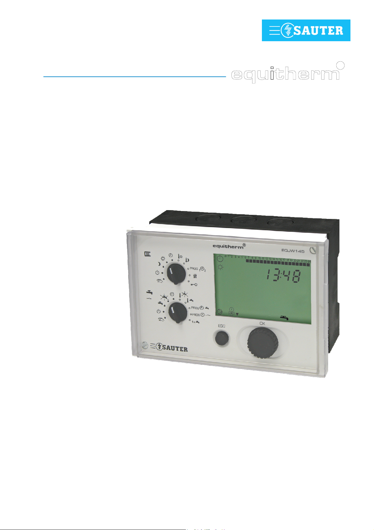
The EQJW 145 is a compact, weather-compensated heating controller used
to regulate flow temperatures and domestic hot water preparation. In
automatic mode, the EQJW 145 reduces the room temperature during the
night (reduced mode) by means of switching commands from the weekly time
switch (weekly switching programme), and during the day it switches to the
normal temperature. Domestic hot water preparation is switched on or off via
another switching programme. There is a choice of two adjustable
temperatures for domestic hot water. The EQJW 145 is suitable for buildings
of all types. A fixed basic programme (factory setting) ensures that
commissioning is simple. Any adaptations to the heating system which might
be needed are implemented using SERVice parameters. Automatic
summertime/wintertime change-over eliminates the need for residents to
adjust the time twice a year. The equitherm
EQJW 145 incorporates a
variety of protective functions such as the anti-frost function and the pump
anti-jamming facility. Additional functions such as automatic switch-off are
also implemented. For every installation, these features ensure optimal
comfort with the minimum use of energy.
Analogue or digital room operating units can be connected to the EQJW 145,
enabling convenient remote control of the controller from the living room.
A programmable output is provided for additional tasks. For example, it may
be used as a pilot timer output, as a signal for a collective fault alarm, and to
activate a circulating pump for domestic hot water. The communication
interface makes it possible to network several controllers, to connect to a
control station and to send alarms to a mobile telephone via SMS.
1.2 Safety information
Special care is required in order to prevent injuries, damage by fire or
damage to equipment. After the device has been installed by a specialist in
accordance with the Installation Instructions enclosed with it (MV506103),
please read these instructions on operating it. Local regulations must be
followed during installation. The controller is not a safety-relevant component.
The anti-frost, overheating protection and flow temperature limitation
functions do not replace the relevant safety equipment.
7010015003 A
© Fr. Sauter AG
9

EQJW145:
General informatio
Heating controller
n
10 7010015003 A
© Fr. Sauter AG
EQJW145:
234
°C
sec1h
123
4
Description
Heating controller
of the operating controls
2 Description of the operating controls
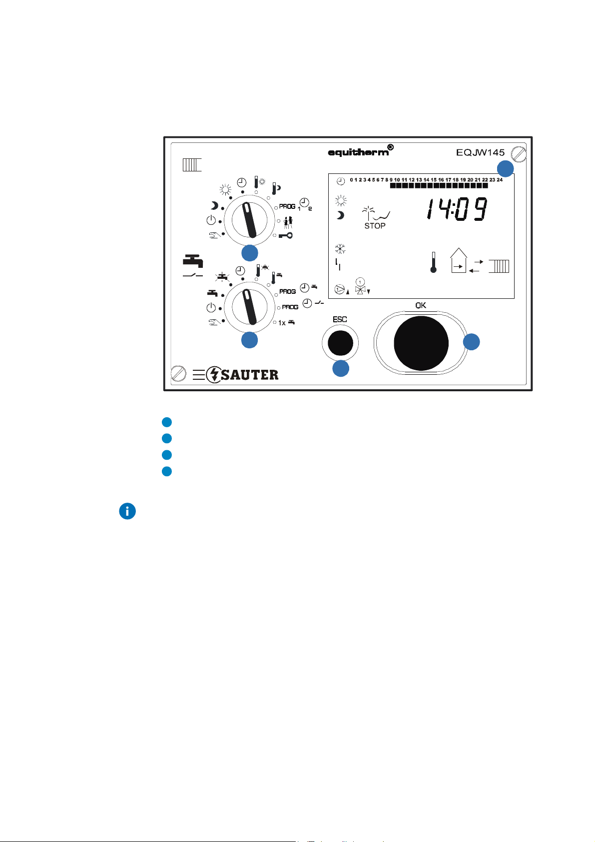
2.1 Front view of the EQJW 145
1
Fig. 1: EQJW 145 - Front view
Rotary switch
Display
ESC button
Input knob
The device has a rotary switch with 10 positions, an input knob and a button.
7010015003 A
© Fr. Sauter AG
11
EQJW145:
Operatingmodes:
Inputs:
Limited (unlimited)
l
Operatingmodes:
Inputs:
domestic hot water temperature
1
2
Description
Heating controller
of the operating controls
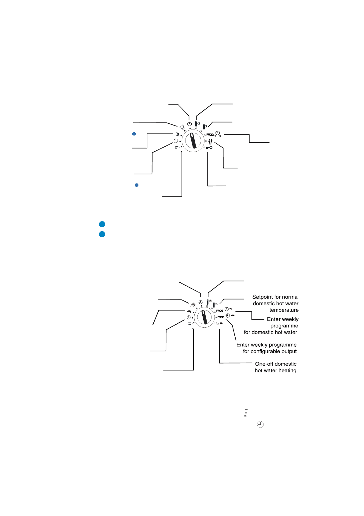
2.2 Top Rotary switches (heating)
The switch positions have these meanings:
Automatic mode according
to switching programme
Regulator is
continuously in
normal mode
1
Regulator is
continuously in
reduced mode
Regulator is
continuously in
back-up mode
2
Access to manual mode
for heating
Fig. 2: EQJW 145 - Top Rotary Switches
Normal mode corresponds to nominal mode as per EN 12098-1.
Back-up mode means that the heating is switched off and the anti-frost function is active.
2.3 Bottom rotary switch (hot water/pilot timer)
Automatic mode for domestic hot
water according to switching
programme
Continuous heating to
increased domestic hot
water temperature
Setpoint adjustment
Normal mode
Setpoint adjustment
Reduced mode
Enter
weekly and
yearly programme for
heating
temperature change
Access to SERVice and
communication leve
Setpoint for increased
12 7010015003 A
Continuous heating
to normal domestic hot
water temperature
Domestic hot water
heating switched off
Access to manual mode
Fig. 3: EQJW 145 - Bottom Rotary Switches
If the rotary switches are used to select a prohibited combination of positions,
e.g. simultaneous entry of setpoints for heating and domestic hot water
preparation, the controller will show this symbol:
In this case, one of the switches should be set to the symbol or to another
mode.
© Fr. Sauter AG

EQJW145:
0 1 2 3 4 5 6 7 8..........21 22 23 24
Description
Heating controller
of the operating controls
2.4 Input knob
2.5 ESC key
You can use the input knob to scroll through menus, and
to select or change values. Unless explicitly described
otherwise, you can scroll through or change
menus/values in a ring structure. There is no 'limit stop'
for adjusting values or scrolling.
The input knob has a key function, i.e. you can press it.
This is used to select the parameter just shown for
changing, or to confirm a flashing value, or to access a
lower menu level.
Press the ESC key to cancel operations, or to return from
a lower menu item to the next level up.
2.6 Display
The device has an LC display (see 2.1), which can show various items of
information at the same time. The next illustration shows what the symbols
mean:
Times for normal mode on the current day
Time, date, setpoints, actual values, etc.
Automatic mode according to the weekly and calendar switching
programme. flashing: temperature change for limited (unlimited) period
Heating circuit is in normal mode flashing. Optimisation takes place on
changing to normal mode.
Heating circuit is in reduced mode flashing. Optimisation takes place on
changing to reduced or off mode.
Heating circuit is in back-up mode. flashing: anti-frost function is active
At least one sensor is faulty (or not connected)
7010015003 A
© Fr. Sauter AG
Heating medium pump is switched on
Final control element 1 is opened ( ) or closed ( )
Final control element 2 is opened ( ) or closed ( )
Display of setpoint temperature. flashing: display of actual temperature
Display of flow temperature
13
EQJW145
Description
: Heating controller
of the operating controls
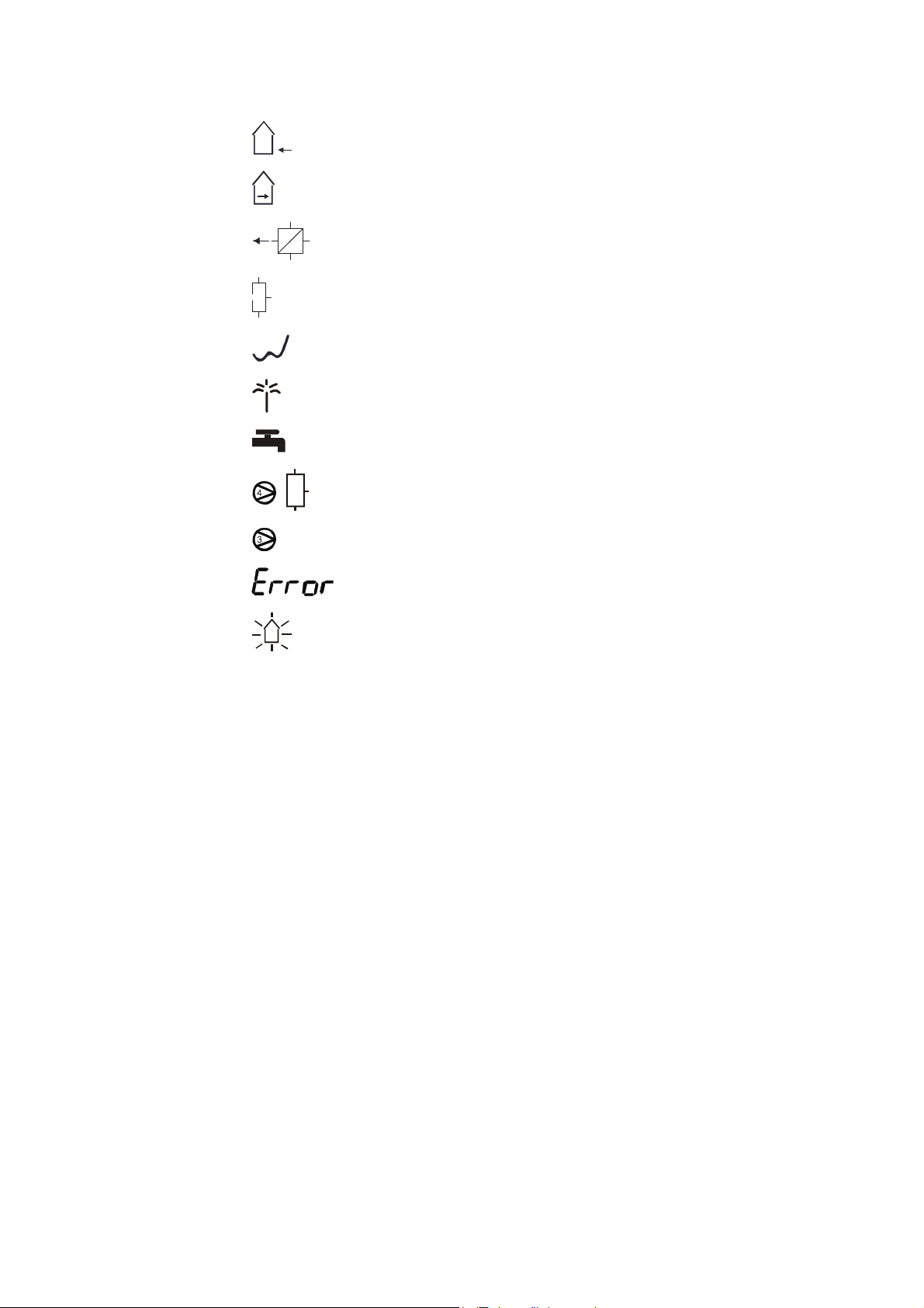
Display of outdoor temperature
Display of room temperature
Display of return temperature
Display of tank temperature
Controller is in summer mode
Calendar switching programme mode is currently active
Domestic hot water. flashing: with increased temperature
Charge pump switched on
2nd charge pump switched on
An error has occurred (see 7)
Floor drying function (heating function) is active
14 7010015003 A
© Fr. Sauter AG
EQJW145:
Commissioning
Heating controller
3 Commissioning
3.1 Operating the device for the first time
When you operate the equitherm
the date and time. Essentially, once this is done, the controller is ready for
use. However, depending on the application, it may be necessary to change
further settings after this.
3.1.1 Setting the time
To enable you to set the time, you must first move the bottom rotary switch
into one of the following positions (see 4.1):
Off mode
Continuous heating to normal DHW temperature
Continuous heating to increased DHW temperature
Automatic mode
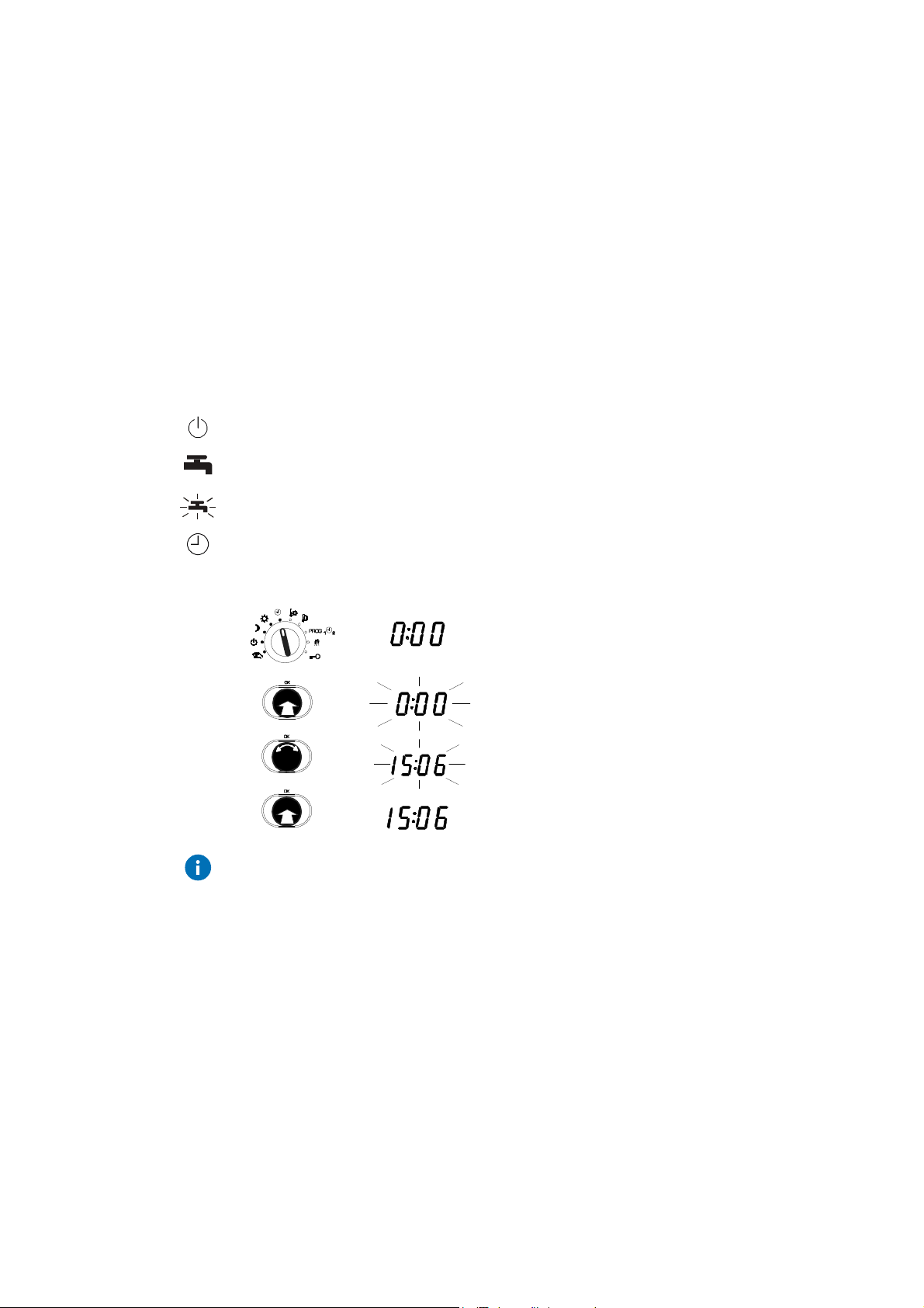
Procedure
EQJW 145 for the first time, you must set
1. Set the top rotary switch to automatic mode.
•
The time is shown.
2. Press the input knob.
•
the time flashes ...
3. Turn the input knob.
•
The time is set.
4. Press the input knob again.
•
The new time is confirmed.
If several devices are connected to each other via a device bus (see 3.4.4)
and you set the clock on one device, the time and date are also set on all the
other devices.
7010015003 A
© Fr. Sauter AG
15
EQJW145:
CAUTION!
Commissioning
Heating controller
3.1.2 Setting the date
To enable you to set the date, you must first move the bottom rotary switch
into one of the following positions (see 4.1):
Off mode
Continuous heating to normal DHW temperature
Continuous heating to increased DHW temperature
Automatic mode
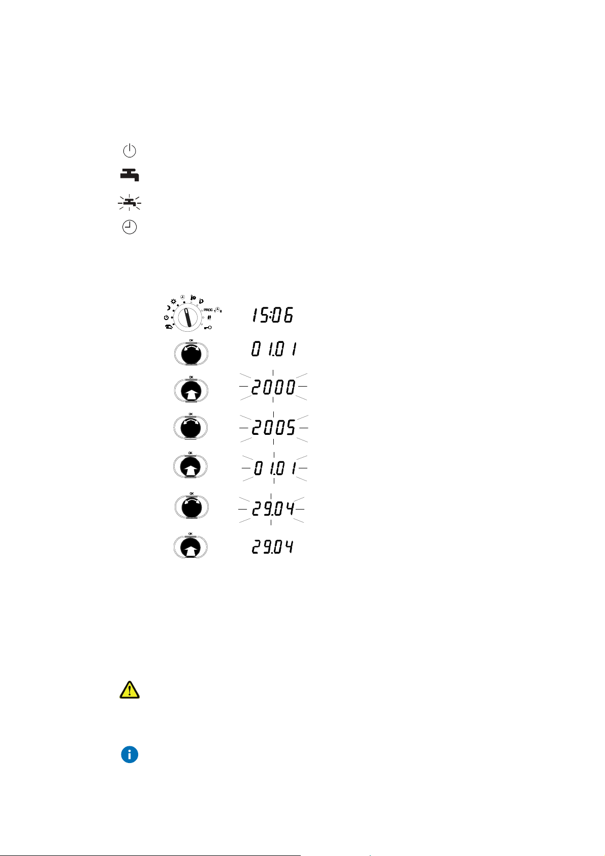
Procedure
1. Set the top rotary switch to automatic mode.
•
The time is shown.
2. Turn the input knob until the date is displayed
(day/month and year are shown alternately).
3. Press the input knob.
•
The number of the year flashes...
4. Turn the input knob.
•
The year is changed.
5. Press the input knob.
•
The year is confirmed and the day/month
is shown.
6. Turn the input knob.
•
The date is changed.
7. Press the input knob,
•
The new date is confirmed.
3.2 Commissioning level
In commissioning level, a specialist can perform the basic settings on the
GZP which are important for commissioning. Direct access to specified
service parameters is enabled.
Incorrect parameterisation (setting) of the heating controller
It can cause major faults or damage to the installation.
The commissioning level must only be enabled by a specialist.
Some of the parameters cannot be changed. They can only be viewed
(version number, status information).
16 7010015003 A
© Fr. Sauter AG

EQJW145:
Commissioning
Heating controller
3.2.1 List of SERVice parameters
The following SERVice parameters can be reached on commissioning level.
Parameter
SP01 Software version Y.XX (read only)
SP06 1 Control model
SP15 40 Proportional band, PI controller in K 2...100 1
SP16 40 MOD3: Proportional band, PI controller in K (2nd control circuit) 2...100 1
SP19 120 Runtime for final control element in sec 30...960 15
SP20 180 Runtime for second final control element in sec
SP34 1 Functions for domestic hot water
Description Range Step value
0...3 1
1 = one control valve on the primary side
2 = one control valve on the secondary side
3 = two control valves on the primary side
30...960 15
MOD1, 2: for diverter valve (SP34 = 3 or 4)
MOD3: for second control valve
0…4 1
0 = not enabled.
1 = MOD 1, 2: with sep. charge pump using one DHW
sensor
2 = MOD 1, 2: with sep. charge pump using two DHW
sensors
3 = MOD 1, 2: with diverter valve using one DHW sensor
4 = MOD 1, 2: with diverter valve using two DHW
sensors
SP36 5 MOD 1, 2: Switching difference for domestic hot water in K 1...30 1
SP37 70 Maximum setpoint for increased DHW temperature/[°C] 10…90 1
SP38 10 Setpoint boost for domestic hot water in K 0…30 1
SP41 1.4 Slope of heating characteristic 0.2...5.0 0.1
SP60 0 Floor drying
Tab. 1: SERVice parameter
0 = not enabled. 7d = enabled. 8 = malfunction
9 = successfully completed
0.7d.8.9 0.7d. 8.9
An overview of the SERVice parameters and explanations for individual
SERVice parameters is given in these sections: 'List of SERVice parameters'
and 'Explanations for individual SERVice parameters'.
7010015003 A
© Fr. Sauter AG
17
EQJW145:
Commissioning
Heating controller
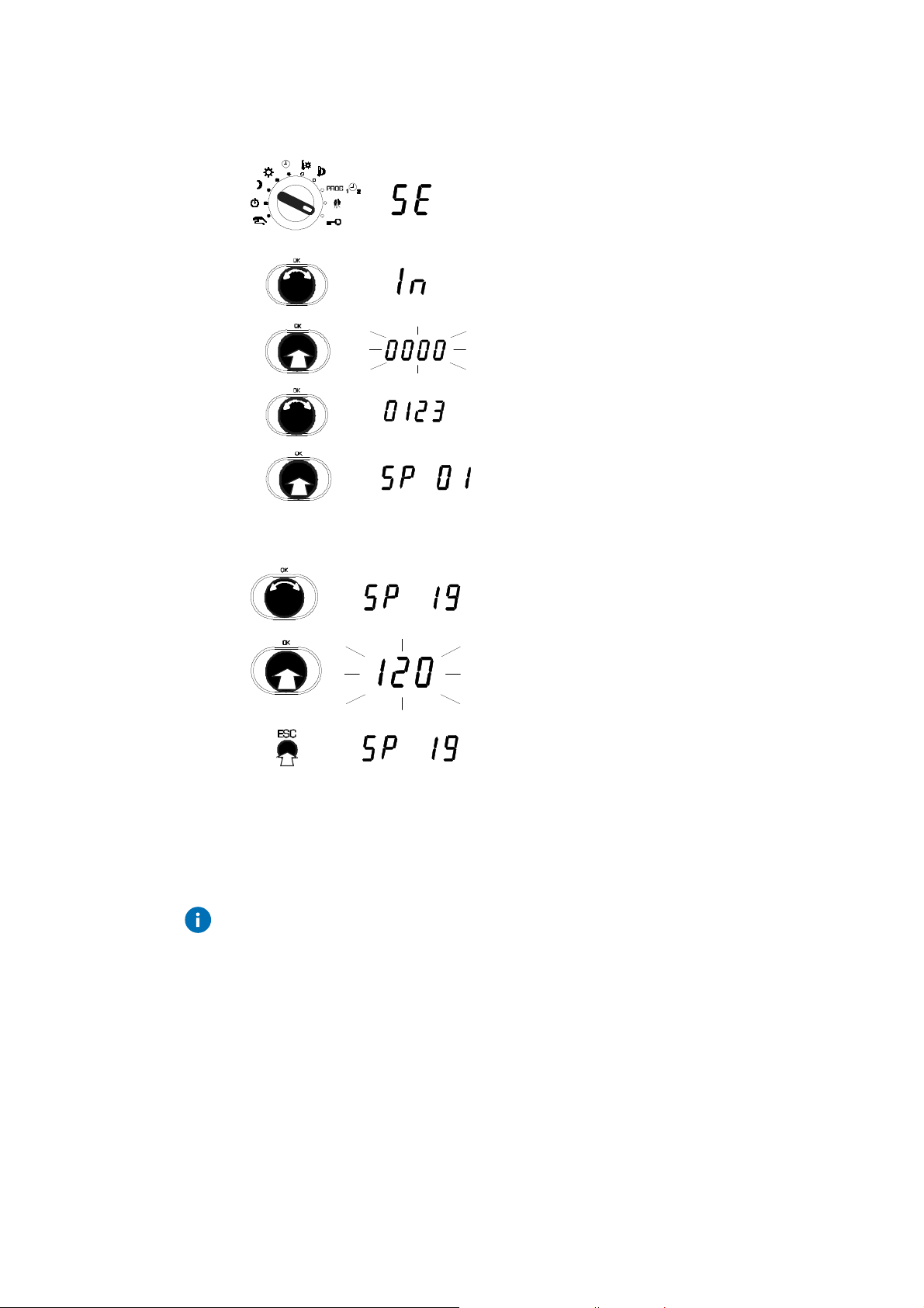
3.2.2 Access to commissioning level
1. Set the upper rotary switch to the Service
position.
2. Press the input knob, select 'In' (=
commissioning)
.
3. Press the input knob.
4. Turn the input knob,
show the code.
5. Press the input knob.
•
The first SERVice parameter is displayed.
3.2.3 View SERVice parameters
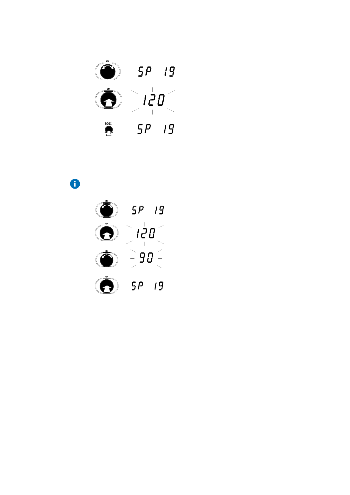
3.2.4 Change SERVice parameters
Press the ESC key to cancel the operation. The value is not accepted unless
it has already been confirmed.
1. Turn the input knob.
2. Select the SERVice parameter you want.
3. Press the input knob.
sec
•
The value of the parameter is shown.
4. To leave the value unchanged.
5. Press ESC to exit the display.
18 7010015003 A
© Fr. Sauter AG
EQJW145:
CAUTION!
Commissioning
Heating controller
3.3 SERVice level
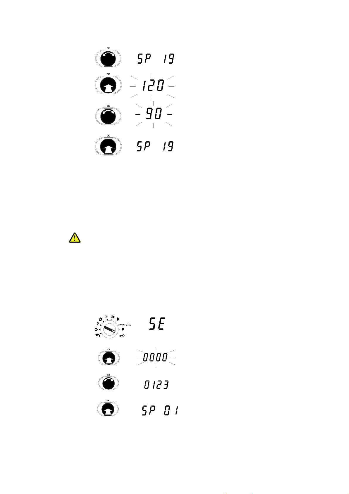
1. Turn the input knob.
2. Select the SERVice parameter you want.
3. Press the input knob.
sec
•
The value of the parameter is shown.
Turn the input knob.
4.
•
sec
The value of the parameter is changed.
5. Press the input knob.
•
The new value is confirmed.
In SERVice level, a specialist can adapt the basic setting of the EQJW 145 to
the installation so as to meet specific requirements. For this purpose, also
please note the installation instructions enclosed with the EQJW 145
(MV506103).
Incorrect parameterisation (setting) of the heating controller
It can cause major faults on the installation, injuries to people or damage to
the installation.
SERVice mode must only be enabled by a specialist.
Some of the parameters cannot be changed - they can only be viewed
(version number, status information).
3.3.1 Access to SERVice level
1. Set the upper rotary switch to the Service
position.
2. Press the input knob.
7010015003 A
© Fr. Sauter AG
3. Turn the input knob.
4. Show the code.
5. Press the input knob.
6. The first SERVice parameter is displayed.
19
EQJW145:
Commissioning
Heating controller
3.3.2 View SERVice parameters
3.3.3 Change SERVice parameters
Press the ESC key to cancel the operation. The value is not accepted unless
it has already been confirmed.
1. Turn the input knob.
2. Select the SERVice parameter you want.
3. Press the input knob.
sec
•
The value of the parameter is shown.
4. To leave the value unchanged, press ESC to
exit the display.
sec
sec
1. Turn the input knob.
2. Select the SERVice parameter you want.
3. Press the input knob.
•
The value of the parameter is shown.
4. Turn the input knob.
•
The value of the parameter is changed.
5. Press the input knob.
•
The new value is confirmed.
20 7010015003 A
© Fr. Sauter AG

EQJW145:
Commissioning
Heating controller
3.3.4 List of SERVice parameters
Parameter Description Range Step value
SP01 Software version Y.XX (read only)
SP02 0 Device status (error coding) (read only)
SP03 View logbook -
1
SP04 0 Software reset
0 = no Reset
1 = factory setting for SE + CO parameters
2 = factory setting for switching commands
3 = factory setting for SE- + CO parameters +
switching commands
SP05 0 Manual mode
0 = manual mode not enabled
1 = manual mode enabled
SP06 1 Control model
1 = one control valve on the primary side
2 = one control valve on the secondary side
3 = two control valves on the primary side
SP07 0 Effect of binary / pulse input (terminals 21, 22)
0 = HK in back-up mode if contact is closed.
1 = HK in reduced mode if contact is closed.
2 = HK in nominal mode if contact is closed.
3 = Pulse input for quantity metering
4 = Seepage limitation
5 = Input for fault signal
0...3 1
0...1 1
0...3 1
0…5 1
SP08 0 Room temperature recording
0 = no room temperature recording
1 = connect room sensor
2 = connect EGS52/15 or EGT 333 with room sensor
3 = connect EGS52/15 or EGT 333 without room
0...4 1
sensor
4 = MOD1,2: 2nd flow sensor for DHW (SP49 = 2)
SP09 0 Connect room temperature
0 = not enabled
1 = enabled if TRi> T
2 = enabled if T
3 = enabled if TRi <> T
Rs
Ri < TRs
Rs
0...3 1
SP10 20 Scanning time for room temperature if connected /[min] 1…100 1
SP11 0
7010015003 A
© Fr. Sauter AG
Correction to room temperature TRiin K
-6.0...+6.0 0.1
21

EQJW145:
Commissioning
Heating controller
Parameter Description Range Step value
SP12 0
SP13 0 Return temperature recording
SP14 0
Correction to outdoor temperature TAin K
0 = return temperature is not recorded
1 = return temperature is recorded
Correction to return temperature TRF (MOD3: TRF of heating circuit)
-10.0…+10.0 0.1
0…1 1
-10.0…+10.0 0.1
SP15 40 Proportional band, PI controller in K 2...100 1
SP16 40 MOD3: Proportional band, PI controller in K (2nd control circuit) 2...100 1
SP17 240 Reset time, PI controller in sec 5...1000 5
SP18 240 MOD3: Reset time, PI controller in sec (2nd control circuit) 5...1000 5
SP19 120 Runtime for final control element in sec 30...960 15
SP20 180 Runtime for second final control element in sec
30...960 15
MOD1, 2: for diverter valve (SP34 = 3 or 4)
MOD3: for second control valve
SP21 5
Minimum limitation for flow temperature TF (heating circuit) in °C
5 …100 1
SP22 75
SP23 90
Maximum limitation for flow temperature TF (heating circuit) in °C
Upper limit value for max. limitation of TRF during heating
20…150 1
5…150 1
in °C
SP24 90
SP25 0 Outdoor temperature at which the sliding part of the limit function for
Lower limit value for max. limitation of TRF during heating in °C
5…150 1
-30...+50 1
TRFbegins, in °C
SP26 1.0
SP27 90
Slope of limitation function for TRFin [K/K]
Maximum limitation for return temperature TRF during DHW
0.0…5.0 0.1
5…150 1
heating in °C
SP28 5 Intervention intensity if limit value for return temperature is violated in
0.1…10 0.1
[K/K]
SP29 no Limit value pulse/min for max. flow or power of heating and DHW no 0.1...16.0.
60...16000
SP30 no Limit value pulse/min for max. flow or power of heating only no 0.1...16.0.
60...16000
SP31 no Limit value pulse/min for max. flow or power of DHW only no 0.1...16.0.
60...16000
0.1/1/10
0.1/1/10
0.1/1/10
SP32 0.0 Intervention intensity in K/min if limit value for flow or power is violated 0.0…30.0 0.1
SP33 no Limit value pulse/min for min. flow or power no. 0.1...16.0.
0.1/1/10
60...16000
22 7010015003 A
© Fr. Sauter AG

EQJW145:
Commissioning
Heating controller
Parameter Description Range Step value
SP34 1 Functions for DHW
0 = not enabled.
1 = MOD 1, 2: with sep. charge pump using one
0…4 1
DHW sensor
2 = MOD 1, 2: with sep. charge pump using two
DHW sensors
3 = MOD 1, 2: with diverter valve using one DHW
sensor
4 = MOD 1, 2: with diverter valve using two DHW
sensors
SP35 60 Maximum setpoint for domestic hot water temp./[°C] 10…70 1
SP36 5 MOD 1, 2: switching difference for DHW in K 1...30 1
SP37 70 Maximum setpoint for increased DHW temperature/[°C] 10…90 1
SP38 10 Setpoint boost for domestic hot water in K 0…30 1
SP39 -30 Outdoor temperature limit value for operation of domestic hot water
-30…50 1
heating in °C
TA < limit value parallel operation
TA > limit value domestic hot water with priority
Note: only valid if value SP34 = 1 or 2
SP40 4 After-run time for charge pump for domestic hot water/[min] 0…20 1
SP41 1.4 Slope of heating characteristic 0.2...5.0 0.1
SP42 10 Setpoint boost for demand request via device bus/ [ K] 0…30 1
SP43 0.0 External heat portion/[K] 0.0...5.0 0.1
SP44 15 Heating limit/[°C] 0...39 1
SP45 1 Outdoor temperature recording for heating limit
0 = TA used unsmoothed for heating limit function
1 = smoothed TA is used for heating limit function
0…1 1
SP46 -16 Design temperature/[°C] -30...0 1
SP47 2 After-run factor for heating medium pump (after-run time = runtime for
1…10 1
final control element x after-run factor)
SP48 1 Anti-frost function
0 = not enabled
1 = enabled
0...1 1
7010015003 A
© Fr. Sauter AG
23

EQJW145:
Commissioning
Heating controller
Parameter Description Range Step value
SP49 0 Configurable output
0 = no function
1 = pilot timer function
2 = 2nd tank charge pump (MOD1, 2 only)
3 = forced control of heating medium pump at low
0…5 1
speed in reduced and back-up mode
4 = collective fault alarm
5 = circulating pump
SP50 0 Pump anti-jamming facility
0 = not enabled. 1 = enabled
0…1 1
SP51 25.10 Summer/winter time changeover 01.01 ...
31.12
SP52 25.03 Winter/summer time changeover
SP51 = SP52 means no summer/winter time
01.01 ...
31.12
changeover
SP53 0 Optimisation
SP60 0 Floor drying
0 = not enabled. 1 = enabled
0 = not enabled
7d = functional heating
25°C = ready-for-laying heating
8 = malfunction
9 = successfully completed
0…1 1
0.7d.25°C.8.9 0.7d.25°C.8
Tab. 2: SERVice parameter
.9
24 7010015003 A
© Fr. Sauter AG

EQJW145:
Commissioning
Heating controller
3.3.5 Explanations for individual SERVice parameters
SP01
SP02
SP03
SP04
View software version
The controller's software version number is shown.
View device status
SERVice parameter 2 allows you to read the device status of the EQJW 145.
Value 0 means that the EQJW 145 is operating without faults. The coding for
faults is shown in section7.1.2. Once the fault is rectified, the value for the
SERVice parameter is reset automatically.
Note: this coded error description is primarily used to signal faults via bus,
modem or SMS. Faults can be conveniently read directly from the ERROR
display on the controller (see7.1).
Logbook
This is not a parameter but an indicator for the logbook, in which the date,
time and type of fault is entered for every fault that occurs during operation.
Further information on this function can be found in section 7.2.
Software reset
Switching commands and/or SERVice or communication parameters are
returned to the factory setting. To do this, the value of the SERVice
parameter must be changed and confirmed. After this, the EQJW 145
performs the relevant reset and assigns value 0 to the parameter.
SP05
SP06
Manual mode
SERVice parameter SP05 is used to disable or enable manual mode. If the
value of the parameter is 0, manual mode is disabled.
Control model
Various control models are stored in the EQJW 145. Use this parameter to
specify the model that the EQJW 145 uses as the basis for control. The
following control models are available for selection.
MOD1: one control valve on the primary side
(SP06 =1)
MOD2: one control valve on the secondary side (SP06 = 2)
MOD3: two control valves on the primary side (SP06 = 3)
With MOD1 and MOD2, it is possible not only to control a heating circuit but
also to prepare DHW. SERVice parameter 33 can be used to configure the
DHW preparation.
With MOD3, the second control valve on the primary side is used for fixedvalue control (e.g. for DHW preparation). The assignment of TF2 or T
RF2
to
the appropriate terminal is done automatically (see wiring diagram). More
information about the control models and the most important applications is
given in the section on 'Information on applications'.
7010015003 A
© Fr. Sauter AG
25

EQJW145:
Commissioning
Heating controller
SP07
Effect of binary / pulse input (terminals 21, 22)
If the external switching contact is closed, this SERVice parameter can be set
appropriately (SP07 = 0, 1 or 2) to influence the heating programme, as long
as the controller is in automatic mode. If the contact is opened again, the
controller will operate according to the weekly / calendar switching
programme again and the following apply:
0 = HK in back-up mode if contact is closed
1 = HK in reduced mode if contact is closed
2 = HK in nominal mode if contact is closed
Alternatively, the input can be used for quantity metering (and therefore for
quantity limitation as well), to limit see page or to forward a fault signal (using
a modem via SMS or via the configurable relay output to another device). For
SP07, the values mean:
3 = input used as pulse input for quantity metering
4 = input used to limit seepage
The minimum flow can be limited. A signal from the auxiliary contacts of a
control unit can be used to do this. If the contact input is closed, the valve
on the primary side closes and is not opened again until the setpoint for
the flow temperature is 5K higher than the actual value.
5 = input is a fault signal input, used to forward fault signals from other
devices
SP08
Room temperature recording
Various types of room temperature sensor can be connected:
0 = no room temperature recording
1 = connect room sensor
2 = connect EGS52/15 or EGT333 with room sensor
3 = connect EGS52/15 or EGT333 without room sensor
4 = only for MOD1,2 with second tank charge pump (SP49 = 2): the
analogue input (terminal 28) is not used as a room sensor but as a second
flow sensor for DHW preparation (also see the section on 'Application
examples').
Room operating unit EGS52/15 allows you to switch over the controller's
mode remotely. Room operating unit EDB100 can also be connected via the
device bus and used to switch the mode over. The mode on the EQJW145
can also be changed using a control station via Modbus. In case of
contradictory commands, the following priority applies: direct settings on
EQJW145 have priority 1. A setting using room operating unit EDB100 via
device bus or a preset via Modbus have priority 2. The setting via the binary
input has priority 3. Settings on room operating unit EGS52/15 have the
lowest priority. If the setpoint for the room temperature is changed via the
setpoint transmitter of the EGS 52/15 or EGT 333 room operating units, it
also changes the actual value for the room temperature at the sensor input of
26 7010015003 A
© Fr. Sauter AG

EQJW145:
Commissioning
Heating controller
the EQJW 145. This, in turn, means that the flow temperature and, therefore,
the heating capacity, for the room are altered accordingly.
SP09
SP10
Connect room temperature
A room temperature sensor (resistance sensor or device bus) is required for
this function. The flow temperature setpoint is changed – in divergence from
the setpoint according to the heating characteristic – if the room temperature
in the reference room diverges from the room setpoint. The change in flow
temperature is limited to a maximum of ± 30K.
SP09 = 1 or 2 can be used to allow the room temperature connection to
influence the flow setpoint in one direction only. The meanings are:
0 = flow temperature is not changed, i.e. the room temperature connection
is not enabled
1 = flow setpoint can only be reduced, i.e. the room temperature
connection is only enabled if TRi> T
2 = flow setpoint can only be increased, i.e. the room temperature
connection is only enabled if TRi< T
3 = flow setpoint can be reduced and increased, i.e. the room temperature
connection is enabled if TRi<> T
Rs
Rs
Rs
Scanning time for room temperature if connected
If the room temperature connection is enabled, this SERVice parameter
determines the period within which a one-off adaptation of the flow setpoint
can occur. In "heavy" buildings with sluggish heating systems, a higher value
is more suitable than it would be for buildings of lightweight construction and
heating that reacts quickly. This time must not be too short, so as to prevent
control fluctuations. The algorithm prevents hunting by changing the flow
setpoint more quickly (at a rate of ±2 K within a scanning period) when the
deviation of the room temperature is diminishing than when it is increasing (at
a rate of ±1 K within a scanning period). If the deviation of the room
temperature is less than 0.25 K, the flow setpoint is not altered. In most
cases, the factory setting (20 minutes) provides satisfactory results for
residential buildings. As a general rule, the factory setting (20 minutes) leads
to satisfactory results in residential buildings.
SP11
SP12
7010015003 A
© Fr. Sauter AG
Open windows or other cooling or heating loads can influence control!
Sudden removal of these influences can lead to the value moving above or
below the room temperature in the opposite direction for short periods!
Correction to room temperature
The measured value for the room temperature is calibrated with the help of
this SERVice parameter. The value that was entered is added to the
measured value for the room temperature.
Correction to outdoor temperature
The measured value for the outdoor temperature is calibrated with the help of
this SERVice parameter. The value that was entered is added to the
measured value for the outdoor temperature.
27

EQJW145:
Commissioning
Heating controller
SP13
SP14
SP15
SP16
SP17
SP18
Return temperature recording
If a return temperature sensor is to be used, this parameter must be set to 1.
Correction to return temperature
The measured value for the return temperature is calibrated with the help of
this SERVice parameter. The value that was entered is added to the
measured value for the return temperature. If there are two return sensors
(MOD3), this parameter only affects the TRF of the heating circuit.
Proportional band
SERVice parameter 15 specifies the proportional band (XP) of PI control for
the flow temperature in K.
Proportional band – 2nd control circuit (only MOD3)
SERVice Parameter 16 specifies the proportional band (XP) of PI control for
the second control circuit in K.
Reset time
SERVice parameter 17 specifies the reset time (TN) of PI control for the flow
temperature in seconds.
Reset time – 2nd control circuit (only MOD3)
SERVice parameter 18 specifies the reset time (TN) of PI control for the
second control circuit in seconds.
SP19
SP20
SP21, 22
SP23 – SP27
Runtime for actuator of control valve
Valves with a motorised actuator need a specified time to open or close
completely. This is known as the valve runtime. This SERVice parameter is
used to set the equitherm
EQJW 145 to the runtime of the valve drive that is
used. Optimal control quality and various protective functions are only
ensured if the valve runtime is set correctly.
Runtime for second actuator
Depending on the control model, a second control valve is used on the
primary side, or a changeover valve is used on the secondary side. SERVice
parameter SP20 is used to set the valve runtime for the second actuator.
Minimum and maximum limits for flow temperature
The setpoint for the flow temperature can be limited. The value of SERVice
parameter SP21 sets the lower limit in this case, and the value of SERVice
parameter 22 sets the upper limit. Parameters SP21 and SP22 specify a
minimum and maximum flow temperature.
Limiting function for the return temperature
A limiting function can be set for the primary-side return temperature of the
converter. If the value falls below the limiting function, the flow temperature is
adjusted (also see SP28). The following illustration shows the limiting
function.
28 7010015003 A
© Fr. Sauter AG

EQJW145:
T
T
L 0BW (R F)
A
Commissioning
Heating controller
R F ma x.
T
L 0 ( RF )
T
L U ( R F)
T
A (R F)
Fig. 4: Limitation function
T
B 1 098 0
The following parameters are available to set the limiting function:
SP23
SP24
SP25
Upper value of maximum limit for primary return temperature
(T
) for heating.
LO(RF)
Lower value of maximum limit for primary return temperature
(T
Outdoor temperature (T
) for heating.
LU(RF)
) at which the sliding portion of
A(RF)
the limiting function for the primary return temperature starts
during heating.
SP26
Slope (S
) of the sliding portion of the limiting function for
L(RF)
the primary return temperature for heating.
SP27
Maximum limit (T
LOBW(RF)
) for the primary return temperature
during DHW heating.
In MOD1 or MOD2, if the heating is in reduced or normal mode and DHW
heating occurs at the same time, the maximum limit value for the primary
return temperature is checked with the outdoor-temperature-dependent value
for the heating circuit and the fixed value for the DHW during this time.
SP 28
7010015003 A
© Fr. Sauter AG
To make the return temperature limitation effective, return temperature
recording must be enabled (see SP13). In summer mode, or if the heating is
in back-up mode, the limitation on the return temperature for the heating is
not enabled.
Intervention intensity if return temperature is exceeded
If the limiting function for the return temperature set with SP23-SP27 is
exceeded, the setpoint for the flow temperature is reduced by the value
indicated in SP28 for each degree of the excess.
29

EQJW145:
Commissioning
Heating controller
SP29 - SP31
Maximum limit values for quantity metering
SP29, SP30 and SP31 specify maximum limit values for quantity metering
(i.e. usually for the flow or heat quantity/power). SP29 defines the maximum
limit value for heating and DHW, SP30 only defines this value for the heating
and SP31 only defines it for DHW. The value is always entered in units of
'pulses per minute'. See the following examples of converting the limit value
for the flow volume or power to the 'Pulses per minute' variable.
Example 1:
The flow volume should be limited to 1.6 m³ / hour.
The flow sensor transmits a signal of 50 pulses / litre.
The following conversion: 1.6 m³ / hour = 1,600 litres / hour and 1600 litres /
hour = 26.67 litres / minute, and the flow sensor variable of 50 pulses / litre,
give a limit value that must be entered on the EQJW145 (SP29, SP30 or
SP31) of 26.67 litres / min x 50 pulses / litre = 1333 pulses / min.
Example 2:
The power in heating mode should be limited to 35kW. With simultaneous
heating operation and DHW heating, 50 kW should be allowed. A heat
quantity meter is available which outputs 1200 pulses / kWh.
The following conversion: 35 kW = 35 kWh / h and the given variable for the
heat quantity meter provide 35 kWh / h x 1200 pulses / kWh = 42,000 pulses
/ h. This gives a value that must be entered on the EQJW145 of 42,000
pulses / h = 42,000 : 60 pulses / min = 700 pulses / min. The second limit
value is 50 kW. The same conversion: (50 kWh / h x 1200 pulses / kWh x 1h
/ 60 min = 1000 pulses / min) gives a value of 1000 pulses / min that must be
entered in the EQJW145. In the EQJW145, a value of 1000 should be
assigned to SP29 and a value of 700 to SP30.
The EQJW145 switches automatically between the following two measuring
methods.
measurement of time interval (time interval measurement) between two
pulses and calculation of the 'pulses per minute' variable
measurement of the number of pulses per minute (pulse measurement) .
If the three set limit values (SP29 to SP31) are in the range 0.1 - 16.0, the
EQJW145 automatically switches over to time interval measurement. If a
value between 60 and 16.000 is entered for one of SERVice parameters
SP29 to SP31, the controller switches over automatically to pulse
measurement.
30 7010015003 A
© Fr. Sauter AG