

Page 1
EQJW145: Heating
controller
Operating manual
7010015003 A
R
Page 2

7010015003 A
Printed in Switzerland
Subject to changes
© Fr. Sauter AG
Im Surinam 55
CH - 4016 Basel
www.sauter-controls.com
2 7010015003 A
© Fr. Sauter AG
Page 3

EQJW145:
Table
Heating controller
of contents
Table of contents
Table of contents ........................................................................................................3
Symbols used in this manual
....................................................................................7
1 General information ............................................................................................9
1.1 Introduction................................................................................................9
1.2 Safety information .....................................................................................9
2 Description of the operating controls .............................................................11
2.1 Front view of the EQJW 145 ...................................................................11
2.2 Top Rotary switches (heating) ................................................................12
2.3 Bottom rotary switch (hot water/pilot timer).............................................12
2.4 Input knob................................................................................................13
2.5 ESC key ..................................................................................................13
2.6 Display.....................................................................................................13
3 Commissioning..................................................................................................15
3.1 Operating the device for the first time ..................................................... 15
3.1.1 Setting the time .......................................................................................15
3.1.2 Setting the date .......................................................................................16
3.2 Commissioning level ...............................................................................16
3.2.1 List of SERVice parameters ....................................................................17
3.2.2 Access to commissioning level ...............................................................18
3.2.3 View SERVice parameters......................................................................18
3.2.4 Change SERVice parameters .................................................................18
3.3 SERVice level ......................................................................................... 19
3.3.1 Access to SERVice level.........................................................................19
3.3.2 View SERVice parameters......................................................................20
3.3.3 Change SERVice parameters .................................................................20
3.3.4 List of SERVice parameters ....................................................................21
3.3.5 Explanations for individual SERVice parameters....................................25
3.4 Communication level...............................................................................38
3.4.1 Access to communication level ...............................................................39
3.4.2 Viewing the communication parameters ................................................. 39
3.4.3 Changing communication parameters ....................................................39
3.4.4 List of communication parameters ..........................................................40
3.4.5 Explanations of individual communication parameters...........................42
7010015003 A
© Fr. Sauter AG
4 Operation............................................................................................................47
4.1 Operating modes.....................................................................................47
4.1.1 Displays when automatic mode is set .....................................................48
3
Page 4

EQJW145:
of contents
Table
Heating controller
4.1.2 Displays when back-up mode, reduced mode and normal mode are set50
4.2 Entering the setpoint temperature in normal mode................................. 51
4.3 Enter setpoint temperature in reduced mode..........................................52
4.4 Weekly switching programme for heating ............................................... 52
4.4.1 Calling up the weekly switching programme........................................... 53
4.4.2 View switching commands ......................................................................53
4.4.3 Enter a switching command ....................................................................54
4.4.4 Changing and deleting a switching command ........................................54
4.5 Calendar switching programme ..............................................................55
4.5.1 Calling up the calendar switching programme ........................................ 55
4.5.2 View switching commands ......................................................................55
4.5.3 Enter a switching command ....................................................................56
4.5.4 Changing and deleting a switching command ........................................56
4.6 Temporary temperature change for the heating circuit...........................57
4.7 Entering DHW temperatures ...................................................................58
4.7.1 Notes on the boosted DHW temperature ................................................ 59
4.8 Weekly switching programme for domestic hot water ............................59
4.8.1 Calling up the weekly switching programme........................................... 60
4.8.2 View switching commands ......................................................................60
4.8.3 Enter a switching command ....................................................................61
4.8.4 Changing and deleting a switching command ........................................61
4.9 Weekly switching programme for pilot timer/circulating pump................ 62
4.10 Calling up the weekly switching programme...........................................63
4.10.1 View switching command........................................................................63
4.10.2 Enter switching command .......................................................................63
4.10.3 Change/delete switching command ........................................................ 64
4.11 Once-only tank charge............................................................................64
5 Manual mode......................................................................................................65
5.1 Access to manual mode (heating) ..........................................................65
5.2 Access to manual mode (domestic hot water, configurable output and
second final control element) ..................................................................65
5.3 Set valve position ....................................................................................65
5.4 Set status of other outputs (pumps, configurable output) for manual
mode .......................................................................................................66
5.5 Exit manual mode ...................................................................................66
5.6 Check measured values in manual mode ............................................... 66
6 Communication functions ................................................................................67
6.1 Bus wiring................................................................................................67
6.2 Device bus............................................................................................... 67
4 7010015003 A
© Fr. Sauter AG
Page 5

EQJW145:
of contents
Table
Heating controller
6.2.1 Assigning addresses ...............................................................................67
6.2.2 Room operating unit EDB 100 ................................................................ 68
6.2.3 Sending and receiving outdoor temperatures ......................................... 68
6.2.4 Requesting and processing a heat requirement .....................................68
6.2.5 Requesting and processing a return temperature ..................................68
6.2.6 Synchronising the time............................................................................68
6.3 Modbus communication ..........................................................................69
6.3.1 Modbus data points (holding register).....................................................70
6.3.2 Modbus data points (coils) ......................................................................74
6.4 Modem operation ....................................................................................75
6.4.1 Connection with the modem....................................................................75
6.4.2 Modbus operation via modem.................................................................75
6.4.3 Sending SMS if there is a fault on the installation ..................................76
6.4.4 Displays for modem operation ................................................................76
6.5 Setting parameters using the PC ............................................................77
7 Faults ..................................................................................................................79
7.1 Displaying faults ......................................................................................79
7.1.1 Error list...................................................................................................79
7.1.2 Device status...........................................................................................79
7.2 Logbook...................................................................................................80
7.3 Reset functions ....................................................................................... 81
7.4 Actions to deal with faulty temperature value measurements ................81
8 Using the controller...........................................................................................83
8.1 General information.................................................................................83
8.2 Examples of use......................................................................................83
8.2.1 Control model 1.......................................................................................84
8.2.2 Control model 2.......................................................................................87
8.2.3 Control model 3.......................................................................................88
9 Economy tips .....................................................................................................89
10 Resistance values for the Ni1000 sensors .....................................................91
7010015003 A
© Fr. Sauter AG
11 Accessories .......................................................................................................93
Wiring diagram ..................................................................................................93
12
13 Dimension drawing ...........................................................................................93
14 Technical data....................................................................................................95
14.1 Overview of technical data......................................................................95
14.2 Overview of main functions.....................................................................97
15 Overview of controller settings......................................................................101
15.1 List of SERVice parameters..................................................................101
5
Page 6

EQJW145:
of contents
Table
Heating controller
15.2 List of communication parameters ........................................................102
15.3 Weekly switching programme: heating .................................................103
15.4 Calendar switching programme: heating ..............................................103
15.5 Weekly switching programme: domestic hot water...............................104
15.6 Weekly switching programme: pilot timer/circulating pump .................. 104
Table of Figures ......................................................................................................105
List of tables............................................................................................................106
Abbreviations..........................................................................................................107
Index ........................................................................................................................108
6 7010015003 A
© Fr. Sauter AG
Page 7

EQJW145:
Symbols
Heating controller
used in this manual
Symbols used in this manual
Information
Information concerning the use of the product.
Warnings
Factory setting of the EQJW 145 (e.g. manufacturer's specified control
values, switching times, etc.)
....
The operating instructions explain the various functions of the device, step by
step, using the following symbols:
'PROG' is shown on the display, flashing
'09:00' is shown on the display, not flashing
Press key ...
7010015003 A
© Fr. Sauter AG
7
Page 8

EQJW145:
Symbols
Heating controller
used in this manual
8 7010015003 A
© Fr. Sauter AG
Page 9

EQJW145:
General information
Heating controller
1 General information
1.1 Introduction
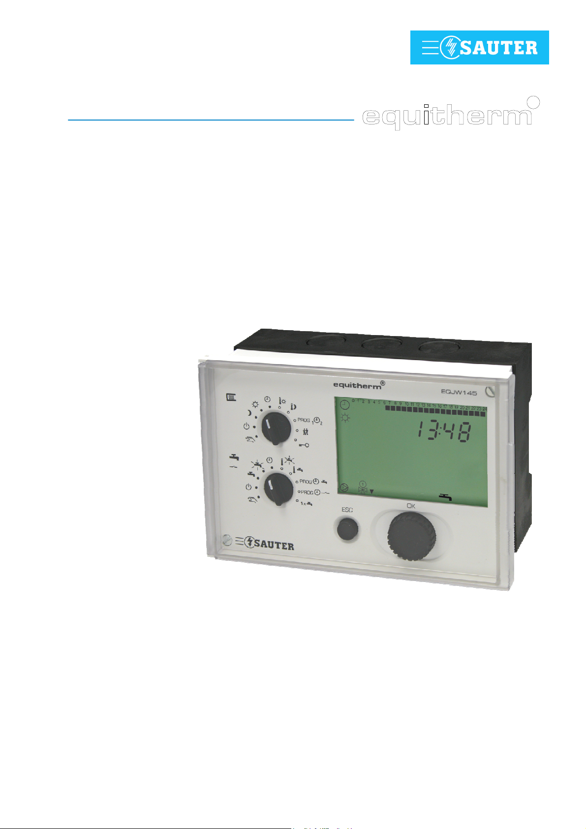
Congratulations! You have chosen a Sauter heating controller. The
equitherm
EQJW 145 is a quality product from one of the leading
manufacturers of control technology products for the heating, ventilation and
air conditioning industry.
The EQJW 145 is a compact, weather-compensated heating controller used
to regulate flow temperatures and domestic hot water preparation. In
automatic mode, the EQJW 145 reduces the room temperature during the
night (reduced mode) by means of switching commands from the weekly time
switch (weekly switching programme), and during the day it switches to the
normal temperature. Domestic hot water preparation is switched on or off via
another switching programme. There is a choice of two adjustable
temperatures for domestic hot water. The EQJW 145 is suitable for buildings
of all types. A fixed basic programme (factory setting) ensures that
commissioning is simple. Any adaptations to the heating system which might
be needed are implemented using SERVice parameters. Automatic
summertime/wintertime change-over eliminates the need for residents to
adjust the time twice a year. The equitherm
EQJW 145 incorporates a
variety of protective functions such as the anti-frost function and the pump
anti-jamming facility. Additional functions such as automatic switch-off are
also implemented. For every installation, these features ensure optimal
comfort with the minimum use of energy.
Analogue or digital room operating units can be connected to the EQJW 145,
enabling convenient remote control of the controller from the living room.
A programmable output is provided for additional tasks. For example, it may
be used as a pilot timer output, as a signal for a collective fault alarm, and to
activate a circulating pump for domestic hot water. The communication
interface makes it possible to network several controllers, to connect to a
control station and to send alarms to a mobile telephone via SMS.
1.2 Safety information
Special care is required in order to prevent injuries, damage by fire or
damage to equipment. After the device has been installed by a specialist in
accordance with the Installation Instructions enclosed with it (MV506103),
please read these instructions on operating it. Local regulations must be
followed during installation. The controller is not a safety-relevant component.
The anti-frost, overheating protection and flow temperature limitation
functions do not replace the relevant safety equipment.
7010015003 A
© Fr. Sauter AG
9
Page 10

EQJW145:
General informatio
Heating controller
n
10 7010015003 A
© Fr. Sauter AG
Page 11
EQJW145:
234
°C
sec1h
123
4
Description
Heating controller
of the operating controls
2 Description of the operating controls
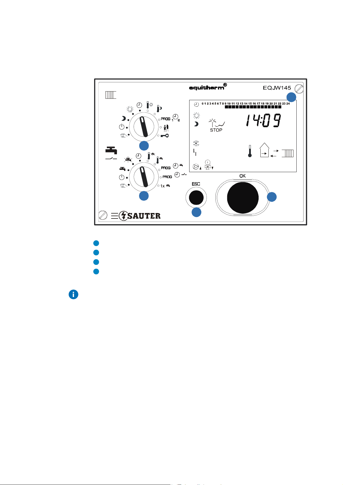
2.1 Front view of the EQJW 145
1
Fig. 1: EQJW 145 - Front view
Rotary switch
Display
ESC button
Input knob
The device has a rotary switch with 10 positions, an input knob and a button.
7010015003 A
© Fr. Sauter AG
11
Page 12
EQJW145:
Operatingmodes:
Inputs:
Limited (unlimited)
l
Operatingmodes:
Inputs:
domestic hot water temperature
1
2
Description
Heating controller
of the operating controls
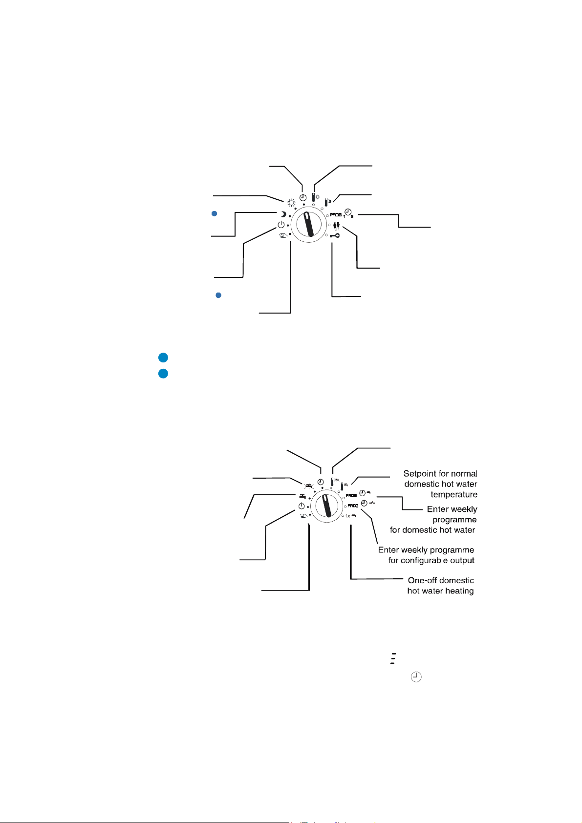
2.2 Top Rotary switches (heating)
The switch positions have these meanings:
Automatic mode according
to switching programme
Regulator is
continuously in
normal mode
1
Regulator is
continuously in
reduced mode
Regulator is
continuously in
back-up mode
2
Access to manual mode
for heating
Fig. 2: EQJW 145 - Top Rotary Switches
Normal mode corresponds to nominal mode as per EN 12098-1.
Back-up mode means that the heating is switched off and the anti-frost function is active.
2.3 Bottom rotary switch (hot water/pilot timer)
Automatic mode for domestic hot
water according to switching
programme
Continuous heating to
increased domestic hot
water temperature
Setpoint adjustment
Normal mode
Setpoint adjustment
Reduced mode
Enter
weekly and
yearly programme for
heating
temperature change
Access to SERVice and
communication leve
Setpoint for increased
12 7010015003 A
Continuous heating
to normal domestic hot
water temperature
Domestic hot water
heating switched off
Access to manual mode
Fig. 3: EQJW 145 - Bottom Rotary Switches
If the rotary switches are used to select a prohibited combination of positions,
e.g. simultaneous entry of setpoints for heating and domestic hot water
preparation, the controller will show this symbol:
In this case, one of the switches should be set to the symbol or to another
mode.
© Fr. Sauter AG
Page 13

EQJW145:
0 1 2 3 4 5 6 7 8..........21 22 23 24
Description
Heating controller
of the operating controls
2.4 Input knob
2.5 ESC key
You can use the input knob to scroll through menus, and
to select or change values. Unless explicitly described
otherwise, you can scroll through or change
menus/values in a ring structure. There is no 'limit stop'
for adjusting values or scrolling.
The input knob has a key function, i.e. you can press it.
This is used to select the parameter just shown for
changing, or to confirm a flashing value, or to access a
lower menu level.
Press the ESC key to cancel operations, or to return from
a lower menu item to the next level up.
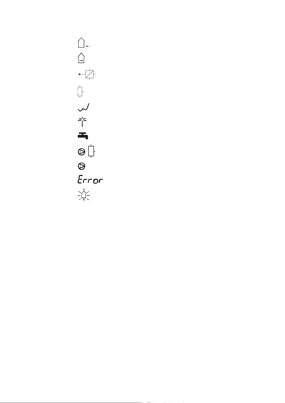
2.6 Display
The device has an LC display (see 2.1), which can show various items of
information at the same time. The next illustration shows what the symbols
mean:
Times for normal mode on the current day
Time, date, setpoints, actual values, etc.
Automatic mode according to the weekly and calendar switching
programme. flashing: temperature change for limited (unlimited) period
Heating circuit is in normal mode flashing. Optimisation takes place on
changing to normal mode.
Heating circuit is in reduced mode flashing. Optimisation takes place on
changing to reduced or off mode.
Heating circuit is in back-up mode. flashing: anti-frost function is active
At least one sensor is faulty (or not connected)
7010015003 A
© Fr. Sauter AG
Heating medium pump is switched on
Final control element 1 is opened ( ) or closed ( )
Final control element 2 is opened ( ) or closed ( )
Display of setpoint temperature. flashing: display of actual temperature
Display of flow temperature
13
Page 14
EQJW145
Description
: Heating controller
of the operating controls
Display of outdoor temperature
Display of room temperature
Display of return temperature
Display of tank temperature
Controller is in summer mode
Calendar switching programme mode is currently active
Domestic hot water. flashing: with increased temperature
Charge pump switched on
2nd charge pump switched on
An error has occurred (see 7)
Floor drying function (heating function) is active
14 7010015003 A
© Fr. Sauter AG
Page 15
EQJW145:
Commissioning
Heating controller
3 Commissioning
3.1 Operating the device for the first time
When you operate the equitherm
the date and time. Essentially, once this is done, the controller is ready for
use. However, depending on the application, it may be necessary to change
further settings after this.
3.1.1 Setting the time
To enable you to set the time, you must first move the bottom rotary switch
into one of the following positions (see 4.1):
Off mode
Continuous heating to normal DHW temperature
Continuous heating to increased DHW temperature
Automatic mode
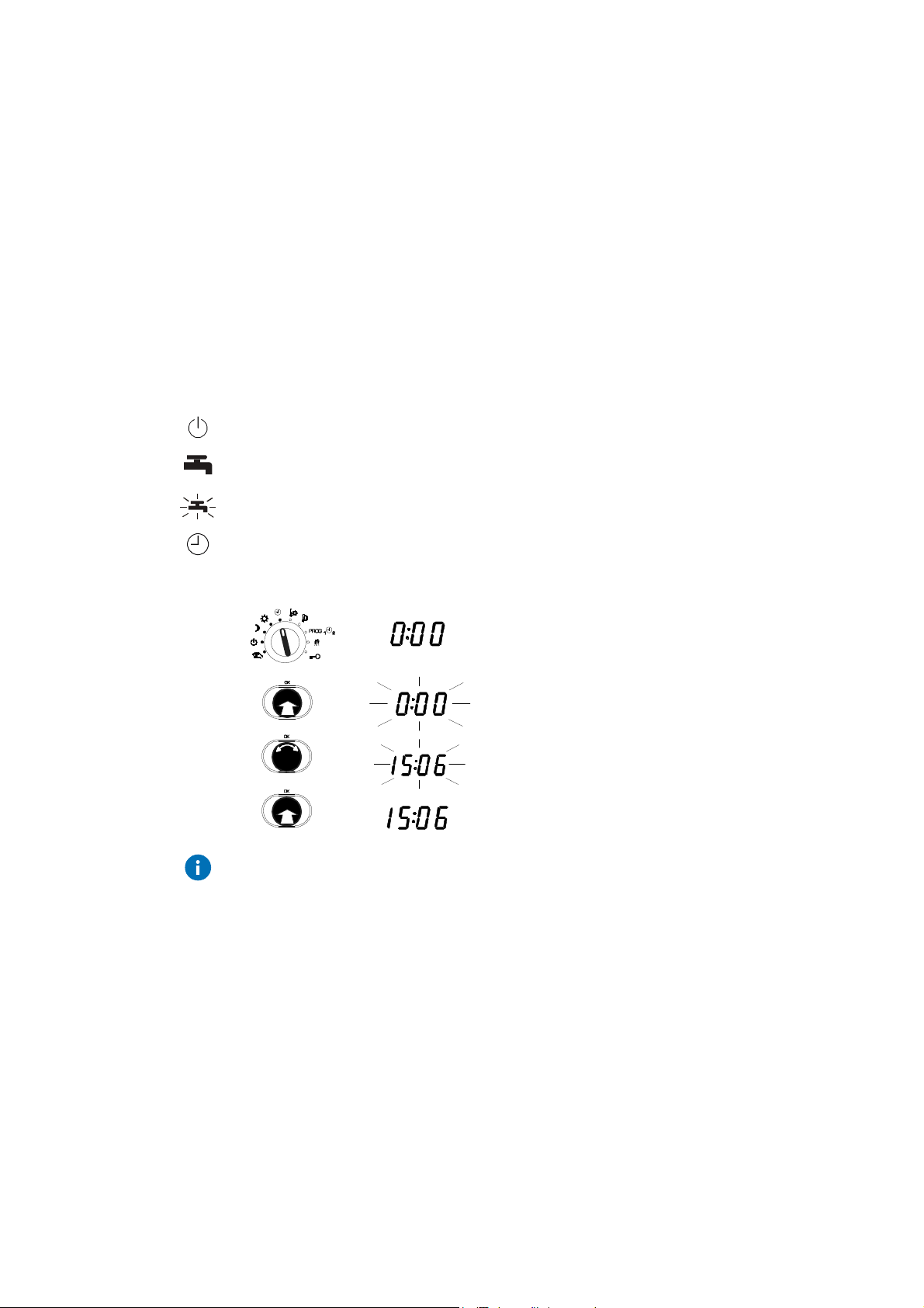
Procedure
EQJW 145 for the first time, you must set
1. Set the top rotary switch to automatic mode.
•
The time is shown.
2. Press the input knob.
•
the time flashes ...
3. Turn the input knob.
•
The time is set.
4. Press the input knob again.
•
The new time is confirmed.
If several devices are connected to each other via a device bus (see 3.4.4)
and you set the clock on one device, the time and date are also set on all the
other devices.
7010015003 A
© Fr. Sauter AG
15
Page 16
EQJW145:
CAUTION!
Commissioning
Heating controller
3.1.2 Setting the date
To enable you to set the date, you must first move the bottom rotary switch
into one of the following positions (see 4.1):
Off mode
Continuous heating to normal DHW temperature
Continuous heating to increased DHW temperature
Automatic mode
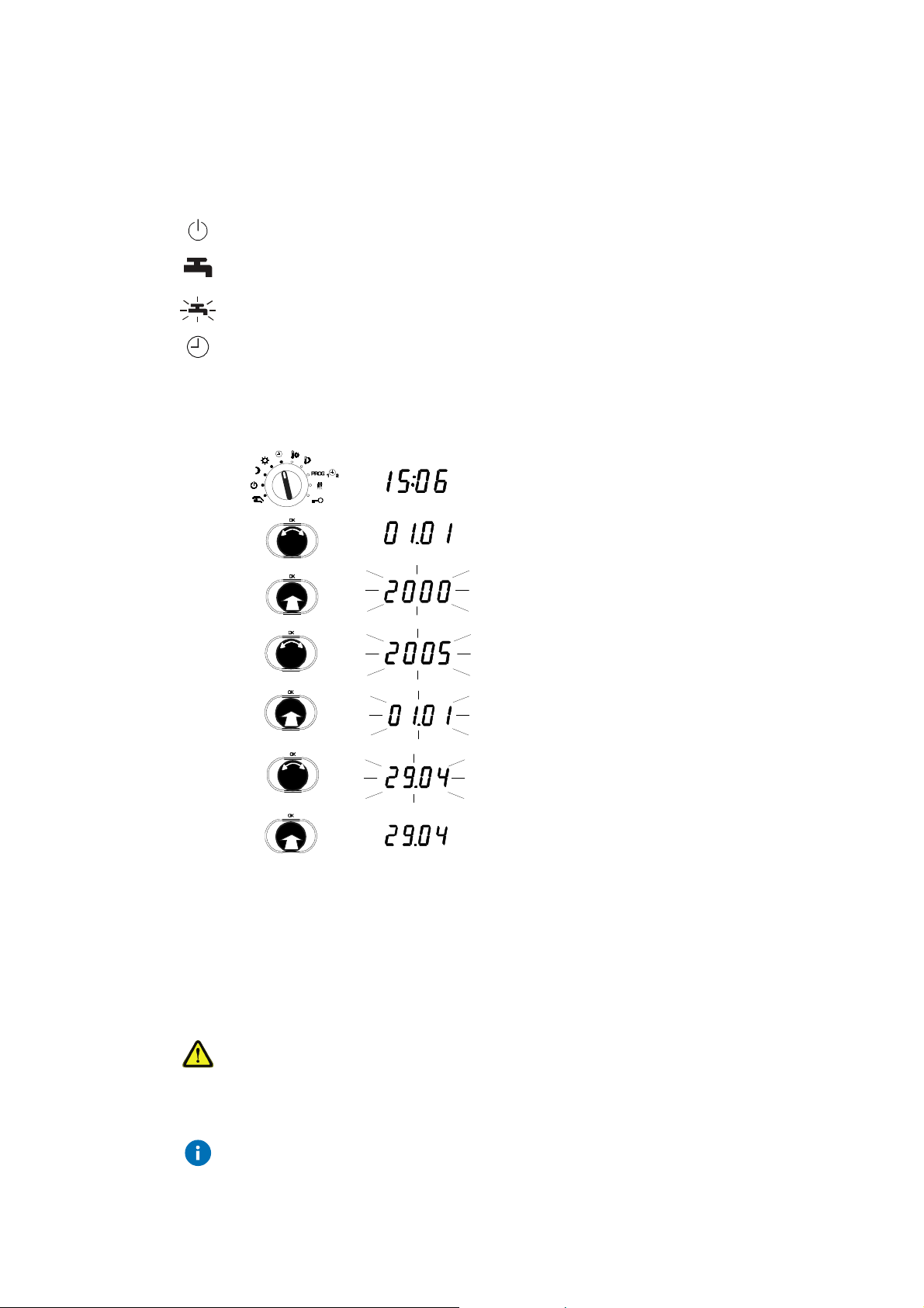
Procedure
1. Set the top rotary switch to automatic mode.
•
The time is shown.
2. Turn the input knob until the date is displayed
(day/month and year are shown alternately).
3. Press the input knob.
•
The number of the year flashes...
4. Turn the input knob.
•
The year is changed.
5. Press the input knob.
•
The year is confirmed and the day/month
is shown.
6. Turn the input knob.
•
The date is changed.
7. Press the input knob,
•
The new date is confirmed.
3.2 Commissioning level
In commissioning level, a specialist can perform the basic settings on the
GZP which are important for commissioning. Direct access to specified
service parameters is enabled.
Incorrect parameterisation (setting) of the heating controller
It can cause major faults or damage to the installation.
The commissioning level must only be enabled by a specialist.
Some of the parameters cannot be changed. They can only be viewed
(version number, status information).
16 7010015003 A
© Fr. Sauter AG
Page 17

EQJW145:
Commissioning
Heating controller
3.2.1 List of SERVice parameters
The following SERVice parameters can be reached on commissioning level.
Parameter
SP01 Software version Y.XX (read only)
SP06 1 Control model
SP15 40 Proportional band, PI controller in K 2...100 1
SP16 40 MOD3: Proportional band, PI controller in K (2nd control circuit) 2...100 1
SP19 120 Runtime for final control element in sec 30...960 15
SP20 180 Runtime for second final control element in sec
SP34 1 Functions for domestic hot water
Description Range Step value
0...3 1
1 = one control valve on the primary side
2 = one control valve on the secondary side
3 = two control valves on the primary side
30...960 15
MOD1, 2: for diverter valve (SP34 = 3 or 4)
MOD3: for second control valve
0…4 1
0 = not enabled.
1 = MOD 1, 2: with sep. charge pump using one DHW
sensor
2 = MOD 1, 2: with sep. charge pump using two DHW
sensors
3 = MOD 1, 2: with diverter valve using one DHW sensor
4 = MOD 1, 2: with diverter valve using two DHW
sensors
SP36 5 MOD 1, 2: Switching difference for domestic hot water in K 1...30 1
SP37 70 Maximum setpoint for increased DHW temperature/[°C] 10…90 1
SP38 10 Setpoint boost for domestic hot water in K 0…30 1
SP41 1.4 Slope of heating characteristic 0.2...5.0 0.1
SP60 0 Floor drying
Tab. 1: SERVice parameter
0 = not enabled. 7d = enabled. 8 = malfunction
9 = successfully completed
0.7d.8.9 0.7d. 8.9
An overview of the SERVice parameters and explanations for individual
SERVice parameters is given in these sections: 'List of SERVice parameters'
and 'Explanations for individual SERVice parameters'.
7010015003 A
© Fr. Sauter AG
17
Page 18
EQJW145:
Commissioning
Heating controller
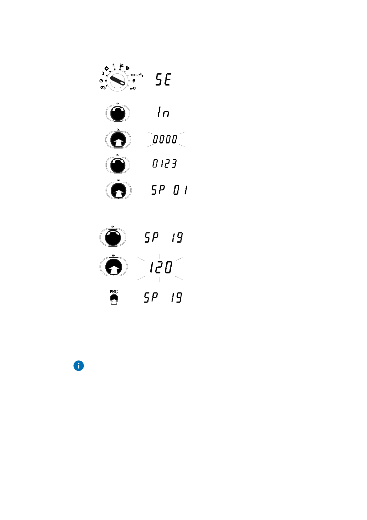
3.2.2 Access to commissioning level
1. Set the upper rotary switch to the Service
position.
2. Press the input knob, select 'In' (=
commissioning)
.
3. Press the input knob.
4. Turn the input knob,
show the code.
5. Press the input knob.
•
The first SERVice parameter is displayed.
3.2.3 View SERVice parameters
3.2.4 Change SERVice parameters
Press the ESC key to cancel the operation. The value is not accepted unless
it has already been confirmed.
1. Turn the input knob.
2. Select the SERVice parameter you want.
3. Press the input knob.
sec
•
The value of the parameter is shown.
4. To leave the value unchanged.
5. Press ESC to exit the display.
18 7010015003 A
© Fr. Sauter AG
Page 19
EQJW145:
CAUTION!
Commissioning
Heating controller
3.3 SERVice level
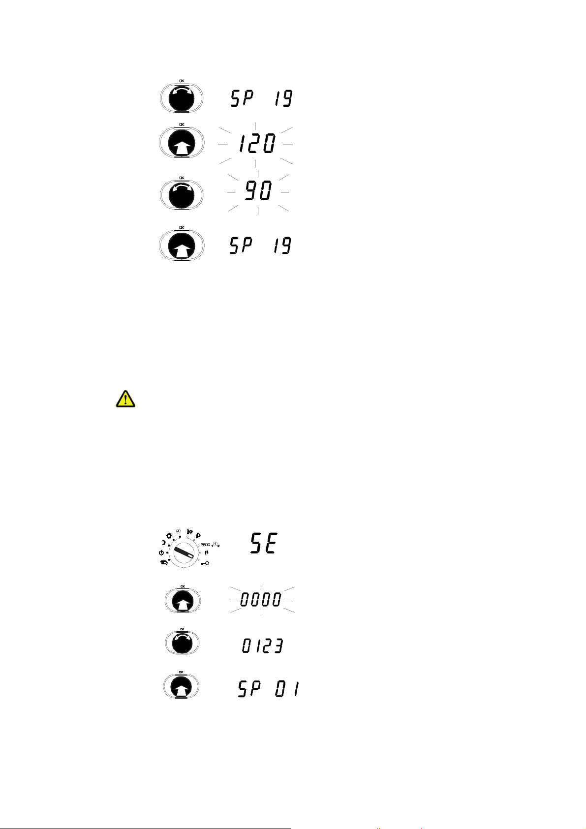
1. Turn the input knob.
2. Select the SERVice parameter you want.
3. Press the input knob.
sec
•
The value of the parameter is shown.
Turn the input knob.
4.
•
sec
The value of the parameter is changed.
5. Press the input knob.
•
The new value is confirmed.
In SERVice level, a specialist can adapt the basic setting of the EQJW 145 to
the installation so as to meet specific requirements. For this purpose, also
please note the installation instructions enclosed with the EQJW 145
(MV506103).
Incorrect parameterisation (setting) of the heating controller
It can cause major faults on the installation, injuries to people or damage to
the installation.
SERVice mode must only be enabled by a specialist.
Some of the parameters cannot be changed - they can only be viewed
(version number, status information).
3.3.1 Access to SERVice level
1. Set the upper rotary switch to the Service
position.
2. Press the input knob.
7010015003 A
© Fr. Sauter AG
3. Turn the input knob.
4. Show the code.
5. Press the input knob.
6. The first SERVice parameter is displayed.
19
Page 20
EQJW145:
Commissioning
Heating controller
3.3.2 View SERVice parameters
3.3.3 Change SERVice parameters
Press the ESC key to cancel the operation. The value is not accepted unless
it has already been confirmed.
1. Turn the input knob.
2. Select the SERVice parameter you want.
3. Press the input knob.
sec
•
The value of the parameter is shown.
4. To leave the value unchanged, press ESC to
exit the display.
sec
sec
1. Turn the input knob.
2. Select the SERVice parameter you want.
3. Press the input knob.
•
The value of the parameter is shown.
4. Turn the input knob.
•
The value of the parameter is changed.
5. Press the input knob.
•
The new value is confirmed.
20 7010015003 A
© Fr. Sauter AG
Page 21

EQJW145:
Commissioning
Heating controller
3.3.4 List of SERVice parameters
Parameter Description Range Step value
SP01 Software version Y.XX (read only)
SP02 0 Device status (error coding) (read only)
SP03 View logbook -
1
SP04 0 Software reset
0 = no Reset
1 = factory setting for SE + CO parameters
2 = factory setting for switching commands
3 = factory setting for SE- + CO parameters +
switching commands
SP05 0 Manual mode
0 = manual mode not enabled
1 = manual mode enabled
SP06 1 Control model
1 = one control valve on the primary side
2 = one control valve on the secondary side
3 = two control valves on the primary side
SP07 0 Effect of binary / pulse input (terminals 21, 22)
0 = HK in back-up mode if contact is closed.
1 = HK in reduced mode if contact is closed.
2 = HK in nominal mode if contact is closed.
3 = Pulse input for quantity metering
4 = Seepage limitation
5 = Input for fault signal
0...3 1
0...1 1
0...3 1
0…5 1
SP08 0 Room temperature recording
0 = no room temperature recording
1 = connect room sensor
2 = connect EGS52/15 or EGT 333 with room sensor
3 = connect EGS52/15 or EGT 333 without room
0...4 1
sensor
4 = MOD1,2: 2nd flow sensor for DHW (SP49 = 2)
SP09 0 Connect room temperature
0 = not enabled
1 = enabled if TRi> T
2 = enabled if T
3 = enabled if TRi <> T
Rs
Ri < TRs
Rs
0...3 1
SP10 20 Scanning time for room temperature if connected /[min] 1…100 1
SP11 0
7010015003 A
© Fr. Sauter AG
Correction to room temperature TRiin K
-6.0...+6.0 0.1
21
Page 22

EQJW145:
Commissioning
Heating controller
Parameter Description Range Step value
SP12 0
SP13 0 Return temperature recording
SP14 0
Correction to outdoor temperature TAin K
0 = return temperature is not recorded
1 = return temperature is recorded
Correction to return temperature TRF (MOD3: TRF of heating circuit)
-10.0…+10.0 0.1
0…1 1
-10.0…+10.0 0.1
SP15 40 Proportional band, PI controller in K 2...100 1
SP16 40 MOD3: Proportional band, PI controller in K (2nd control circuit) 2...100 1
SP17 240 Reset time, PI controller in sec 5...1000 5
SP18 240 MOD3: Reset time, PI controller in sec (2nd control circuit) 5...1000 5
SP19 120 Runtime for final control element in sec 30...960 15
SP20 180 Runtime for second final control element in sec
30...960 15
MOD1, 2: for diverter valve (SP34 = 3 or 4)
MOD3: for second control valve
SP21 5
Minimum limitation for flow temperature TF (heating circuit) in °C
5 …100 1
SP22 75
SP23 90
Maximum limitation for flow temperature TF (heating circuit) in °C
Upper limit value for max. limitation of TRF during heating
20…150 1
5…150 1
in °C
SP24 90
SP25 0 Outdoor temperature at which the sliding part of the limit function for
Lower limit value for max. limitation of TRF during heating in °C
5…150 1
-30...+50 1
TRFbegins, in °C
SP26 1.0
SP27 90
Slope of limitation function for TRFin [K/K]
Maximum limitation for return temperature TRF during DHW
0.0…5.0 0.1
5…150 1
heating in °C
SP28 5 Intervention intensity if limit value for return temperature is violated in
0.1…10 0.1
[K/K]
SP29 no Limit value pulse/min for max. flow or power of heating and DHW no 0.1...16.0.
60...16000
SP30 no Limit value pulse/min for max. flow or power of heating only no 0.1...16.0.
60...16000
SP31 no Limit value pulse/min for max. flow or power of DHW only no 0.1...16.0.
60...16000
0.1/1/10
0.1/1/10
0.1/1/10
SP32 0.0 Intervention intensity in K/min if limit value for flow or power is violated 0.0…30.0 0.1
SP33 no Limit value pulse/min for min. flow or power no. 0.1...16.0.
0.1/1/10
60...16000
22 7010015003 A
© Fr. Sauter AG
Page 23

EQJW145:
Commissioning
Heating controller
Parameter Description Range Step value
SP34 1 Functions for DHW
0 = not enabled.
1 = MOD 1, 2: with sep. charge pump using one
0…4 1
DHW sensor
2 = MOD 1, 2: with sep. charge pump using two
DHW sensors
3 = MOD 1, 2: with diverter valve using one DHW
sensor
4 = MOD 1, 2: with diverter valve using two DHW
sensors
SP35 60 Maximum setpoint for domestic hot water temp./[°C] 10…70 1
SP36 5 MOD 1, 2: switching difference for DHW in K 1...30 1
SP37 70 Maximum setpoint for increased DHW temperature/[°C] 10…90 1
SP38 10 Setpoint boost for domestic hot water in K 0…30 1
SP39 -30 Outdoor temperature limit value for operation of domestic hot water
-30…50 1
heating in °C
TA < limit value parallel operation
TA > limit value domestic hot water with priority
Note: only valid if value SP34 = 1 or 2
SP40 4 After-run time for charge pump for domestic hot water/[min] 0…20 1
SP41 1.4 Slope of heating characteristic 0.2...5.0 0.1
SP42 10 Setpoint boost for demand request via device bus/ [ K] 0…30 1
SP43 0.0 External heat portion/[K] 0.0...5.0 0.1
SP44 15 Heating limit/[°C] 0...39 1
SP45 1 Outdoor temperature recording for heating limit
0 = TA used unsmoothed for heating limit function
1 = smoothed TA is used for heating limit function
0…1 1
SP46 -16 Design temperature/[°C] -30...0 1
SP47 2 After-run factor for heating medium pump (after-run time = runtime for
1…10 1
final control element x after-run factor)
SP48 1 Anti-frost function
0 = not enabled
1 = enabled
0...1 1
7010015003 A
© Fr. Sauter AG
23
Page 24

EQJW145:
Commissioning
Heating controller
Parameter Description Range Step value
SP49 0 Configurable output
0 = no function
1 = pilot timer function
2 = 2nd tank charge pump (MOD1, 2 only)
3 = forced control of heating medium pump at low
0…5 1
speed in reduced and back-up mode
4 = collective fault alarm
5 = circulating pump
SP50 0 Pump anti-jamming facility
0 = not enabled. 1 = enabled
0…1 1
SP51 25.10 Summer/winter time changeover 01.01 ...
31.12
SP52 25.03 Winter/summer time changeover
SP51 = SP52 means no summer/winter time
01.01 ...
31.12
changeover
SP53 0 Optimisation
SP60 0 Floor drying
0 = not enabled. 1 = enabled
0 = not enabled
7d = functional heating
25°C = ready-for-laying heating
8 = malfunction
9 = successfully completed
0…1 1
0.7d.25°C.8.9 0.7d.25°C.8
Tab. 2: SERVice parameter
.9
24 7010015003 A
© Fr. Sauter AG
Page 25

EQJW145:
Commissioning
Heating controller
3.3.5 Explanations for individual SERVice parameters
SP01
SP02
SP03
SP04
View software version
The controller's software version number is shown.
View device status
SERVice parameter 2 allows you to read the device status of the EQJW 145.
Value 0 means that the EQJW 145 is operating without faults. The coding for
faults is shown in section7.1.2. Once the fault is rectified, the value for the
SERVice parameter is reset automatically.
Note: this coded error description is primarily used to signal faults via bus,
modem or SMS. Faults can be conveniently read directly from the ERROR
display on the controller (see7.1).
Logbook
This is not a parameter but an indicator for the logbook, in which the date,
time and type of fault is entered for every fault that occurs during operation.
Further information on this function can be found in section 7.2.
Software reset
Switching commands and/or SERVice or communication parameters are
returned to the factory setting. To do this, the value of the SERVice
parameter must be changed and confirmed. After this, the EQJW 145
performs the relevant reset and assigns value 0 to the parameter.
SP05
SP06
Manual mode
SERVice parameter SP05 is used to disable or enable manual mode. If the
value of the parameter is 0, manual mode is disabled.
Control model
Various control models are stored in the EQJW 145. Use this parameter to
specify the model that the EQJW 145 uses as the basis for control. The
following control models are available for selection.
MOD1: one control valve on the primary side
(SP06 =1)
MOD2: one control valve on the secondary side (SP06 = 2)
MOD3: two control valves on the primary side (SP06 = 3)
With MOD1 and MOD2, it is possible not only to control a heating circuit but
also to prepare DHW. SERVice parameter 33 can be used to configure the
DHW preparation.
With MOD3, the second control valve on the primary side is used for fixedvalue control (e.g. for DHW preparation). The assignment of TF2 or T
RF2
to
the appropriate terminal is done automatically (see wiring diagram). More
information about the control models and the most important applications is
given in the section on 'Information on applications'.
7010015003 A
© Fr. Sauter AG
25
Page 26

EQJW145:
Commissioning
Heating controller
SP07
Effect of binary / pulse input (terminals 21, 22)
If the external switching contact is closed, this SERVice parameter can be set
appropriately (SP07 = 0, 1 or 2) to influence the heating programme, as long
as the controller is in automatic mode. If the contact is opened again, the
controller will operate according to the weekly / calendar switching
programme again and the following apply:
0 = HK in back-up mode if contact is closed
1 = HK in reduced mode if contact is closed
2 = HK in nominal mode if contact is closed
Alternatively, the input can be used for quantity metering (and therefore for
quantity limitation as well), to limit see page or to forward a fault signal (using
a modem via SMS or via the configurable relay output to another device). For
SP07, the values mean:
3 = input used as pulse input for quantity metering
4 = input used to limit seepage
The minimum flow can be limited. A signal from the auxiliary contacts of a
control unit can be used to do this. If the contact input is closed, the valve
on the primary side closes and is not opened again until the setpoint for
the flow temperature is 5K higher than the actual value.
5 = input is a fault signal input, used to forward fault signals from other
devices
SP08
Room temperature recording
Various types of room temperature sensor can be connected:
0 = no room temperature recording
1 = connect room sensor
2 = connect EGS52/15 or EGT333 with room sensor
3 = connect EGS52/15 or EGT333 without room sensor
4 = only for MOD1,2 with second tank charge pump (SP49 = 2): the
analogue input (terminal 28) is not used as a room sensor but as a second
flow sensor for DHW preparation (also see the section on 'Application
examples').
Room operating unit EGS52/15 allows you to switch over the controller's
mode remotely. Room operating unit EDB100 can also be connected via the
device bus and used to switch the mode over. The mode on the EQJW145
can also be changed using a control station via Modbus. In case of
contradictory commands, the following priority applies: direct settings on
EQJW145 have priority 1. A setting using room operating unit EDB100 via
device bus or a preset via Modbus have priority 2. The setting via the binary
input has priority 3. Settings on room operating unit EGS52/15 have the
lowest priority. If the setpoint for the room temperature is changed via the
setpoint transmitter of the EGS 52/15 or EGT 333 room operating units, it
also changes the actual value for the room temperature at the sensor input of
26 7010015003 A
© Fr. Sauter AG
Page 27

EQJW145:
Commissioning
Heating controller
the EQJW 145. This, in turn, means that the flow temperature and, therefore,
the heating capacity, for the room are altered accordingly.
SP09
SP10
Connect room temperature
A room temperature sensor (resistance sensor or device bus) is required for
this function. The flow temperature setpoint is changed – in divergence from
the setpoint according to the heating characteristic – if the room temperature
in the reference room diverges from the room setpoint. The change in flow
temperature is limited to a maximum of ± 30K.
SP09 = 1 or 2 can be used to allow the room temperature connection to
influence the flow setpoint in one direction only. The meanings are:
0 = flow temperature is not changed, i.e. the room temperature connection
is not enabled
1 = flow setpoint can only be reduced, i.e. the room temperature
connection is only enabled if TRi> T
2 = flow setpoint can only be increased, i.e. the room temperature
connection is only enabled if TRi< T
3 = flow setpoint can be reduced and increased, i.e. the room temperature
connection is enabled if TRi<> T
Rs
Rs
Rs
Scanning time for room temperature if connected
If the room temperature connection is enabled, this SERVice parameter
determines the period within which a one-off adaptation of the flow setpoint
can occur. In "heavy" buildings with sluggish heating systems, a higher value
is more suitable than it would be for buildings of lightweight construction and
heating that reacts quickly. This time must not be too short, so as to prevent
control fluctuations. The algorithm prevents hunting by changing the flow
setpoint more quickly (at a rate of ±2 K within a scanning period) when the
deviation of the room temperature is diminishing than when it is increasing (at
a rate of ±1 K within a scanning period). If the deviation of the room
temperature is less than 0.25 K, the flow setpoint is not altered. In most
cases, the factory setting (20 minutes) provides satisfactory results for
residential buildings. As a general rule, the factory setting (20 minutes) leads
to satisfactory results in residential buildings.
SP11
SP12
7010015003 A
© Fr. Sauter AG
Open windows or other cooling or heating loads can influence control!
Sudden removal of these influences can lead to the value moving above or
below the room temperature in the opposite direction for short periods!
Correction to room temperature
The measured value for the room temperature is calibrated with the help of
this SERVice parameter. The value that was entered is added to the
measured value for the room temperature.
Correction to outdoor temperature
The measured value for the outdoor temperature is calibrated with the help of
this SERVice parameter. The value that was entered is added to the
measured value for the outdoor temperature.
27
Page 28

EQJW145:
Commissioning
Heating controller
SP13
SP14
SP15
SP16
SP17
SP18
Return temperature recording
If a return temperature sensor is to be used, this parameter must be set to 1.
Correction to return temperature
The measured value for the return temperature is calibrated with the help of
this SERVice parameter. The value that was entered is added to the
measured value for the return temperature. If there are two return sensors
(MOD3), this parameter only affects the TRF of the heating circuit.
Proportional band
SERVice parameter 15 specifies the proportional band (XP) of PI control for
the flow temperature in K.
Proportional band – 2nd control circuit (only MOD3)
SERVice Parameter 16 specifies the proportional band (XP) of PI control for
the second control circuit in K.
Reset time
SERVice parameter 17 specifies the reset time (TN) of PI control for the flow
temperature in seconds.
Reset time – 2nd control circuit (only MOD3)
SERVice parameter 18 specifies the reset time (TN) of PI control for the
second control circuit in seconds.
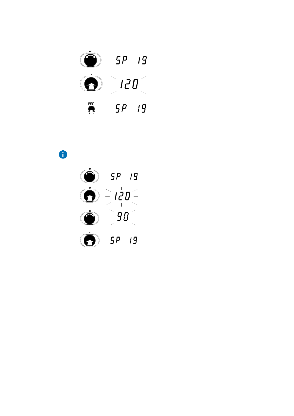
SP19
SP20
SP21, 22
SP23 – SP27
Runtime for actuator of control valve
Valves with a motorised actuator need a specified time to open or close
completely. This is known as the valve runtime. This SERVice parameter is
used to set the equitherm
EQJW 145 to the runtime of the valve drive that is
used. Optimal control quality and various protective functions are only
ensured if the valve runtime is set correctly.
Runtime for second actuator
Depending on the control model, a second control valve is used on the
primary side, or a changeover valve is used on the secondary side. SERVice
parameter SP20 is used to set the valve runtime for the second actuator.
Minimum and maximum limits for flow temperature
The setpoint for the flow temperature can be limited. The value of SERVice
parameter SP21 sets the lower limit in this case, and the value of SERVice
parameter 22 sets the upper limit. Parameters SP21 and SP22 specify a
minimum and maximum flow temperature.
Limiting function for the return temperature
A limiting function can be set for the primary-side return temperature of the
converter. If the value falls below the limiting function, the flow temperature is
adjusted (also see SP28). The following illustration shows the limiting
function.
28 7010015003 A
© Fr. Sauter AG
Page 29

EQJW145:
T
T
L 0BW (R F)
A
Commissioning
Heating controller
R F ma x.
T
L 0 ( RF )
T
L U ( R F)
T
A (R F)
Fig. 4: Limitation function
T
B 1 098 0
The following parameters are available to set the limiting function:
SP23
SP24
SP25
Upper value of maximum limit for primary return temperature
(T
) for heating.
LO(RF)
Lower value of maximum limit for primary return temperature
(T
Outdoor temperature (T
) for heating.
LU(RF)
) at which the sliding portion of
A(RF)
the limiting function for the primary return temperature starts
during heating.
SP26
Slope (S
) of the sliding portion of the limiting function for
L(RF)
the primary return temperature for heating.
SP27
Maximum limit (T
LOBW(RF)
) for the primary return temperature
during DHW heating.
In MOD1 or MOD2, if the heating is in reduced or normal mode and DHW
heating occurs at the same time, the maximum limit value for the primary
return temperature is checked with the outdoor-temperature-dependent value
for the heating circuit and the fixed value for the DHW during this time.
SP 28
7010015003 A
© Fr. Sauter AG
To make the return temperature limitation effective, return temperature
recording must be enabled (see SP13). In summer mode, or if the heating is
in back-up mode, the limitation on the return temperature for the heating is
not enabled.
Intervention intensity if return temperature is exceeded
If the limiting function for the return temperature set with SP23-SP27 is
exceeded, the setpoint for the flow temperature is reduced by the value
indicated in SP28 for each degree of the excess.
29
Page 30

EQJW145:
Commissioning
Heating controller
SP29 - SP31
Maximum limit values for quantity metering
SP29, SP30 and SP31 specify maximum limit values for quantity metering
(i.e. usually for the flow or heat quantity/power). SP29 defines the maximum
limit value for heating and DHW, SP30 only defines this value for the heating
and SP31 only defines it for DHW. The value is always entered in units of
'pulses per minute'. See the following examples of converting the limit value
for the flow volume or power to the 'Pulses per minute' variable.
Example 1:
The flow volume should be limited to 1.6 m³ / hour.
The flow sensor transmits a signal of 50 pulses / litre.
The following conversion: 1.6 m³ / hour = 1,600 litres / hour and 1600 litres /
hour = 26.67 litres / minute, and the flow sensor variable of 50 pulses / litre,
give a limit value that must be entered on the EQJW145 (SP29, SP30 or
SP31) of 26.67 litres / min x 50 pulses / litre = 1333 pulses / min.
Example 2:
The power in heating mode should be limited to 35kW. With simultaneous
heating operation and DHW heating, 50 kW should be allowed. A heat
quantity meter is available which outputs 1200 pulses / kWh.
The following conversion: 35 kW = 35 kWh / h and the given variable for the
heat quantity meter provide 35 kWh / h x 1200 pulses / kWh = 42,000 pulses
/ h. This gives a value that must be entered on the EQJW145 of 42,000
pulses / h = 42,000 : 60 pulses / min = 700 pulses / min. The second limit
value is 50 kW. The same conversion: (50 kWh / h x 1200 pulses / kWh x 1h
/ 60 min = 1000 pulses / min) gives a value of 1000 pulses / min that must be
entered in the EQJW145. In the EQJW145, a value of 1000 should be
assigned to SP29 and a value of 700 to SP30.
The EQJW145 switches automatically between the following two measuring
methods.
measurement of time interval (time interval measurement) between two
pulses and calculation of the 'pulses per minute' variable
measurement of the number of pulses per minute (pulse measurement) .
If the three set limit values (SP29 to SP31) are in the range 0.1 - 16.0, the
EQJW145 automatically switches over to time interval measurement. If a
value between 60 and 16.000 is entered for one of SERVice parameters
SP29 to SP31, the controller switches over automatically to pulse
measurement.
30 7010015003 A
© Fr. Sauter AG
Page 31

EQJW145:
Commissioning
Heating controller
A limit value of between 16 and 60 pulses / minute cannot be entered
because the measurement accuracy required for control is no longer
available in this range. If a value in the range from 60 to 16,000 has been
entered for one of the limit values (SP29, SP30 or SP31), the other two
limit values must be in the range from 60 to 16,000 or must be disabled
(value of SERVice parameter = 'no'). Otherwise, there may be faulty
monitoring of the limit value leading to faulty control behaviour. During DHW
heating at increased DHW temperature, the limiting function is not enabled
so that protection against legionella can be enabled if required.
SP32
SP33
SP34
Intervention intensity in case of violation of maximum limit value for quantity
measurement
The flow temperature is reduced each minute by the value that was entered
for SP32 if the limit for quantity metering is violated. The flow temperature is
adapted 'continuously' (i.e. about once a second) to its value in this case. If
the value falls below the limit value for quantity measurement again, the flow
temperature is increased again at 1/5 of the set intervention intensity.
Limit value for minimum flow or power
This function is used to limit see page. It prevents a constant low flow if the
energy requirement is low. In this case, the mixer is closed and only opened
again if a control divergence of over 5 K occurs. The value is entered in
pulses / min.
To convert the limit value for flow or power into a value in units of pulses /
min, see the examples given with the explanations for SP29 to SP32.
Functions for DHW
The plant structure for control model MOD1, 2 (see SP06, control models)
can be extended by adding DHW preparation. SP34 must be set as per the
existing DHW preparation.
7010015003 A
© Fr. Sauter AG
separate charge pump diverter valve
one DHW sensor
two DHW sensors
Tab. 3: DHW preparation
SP34 = 1,
SP34 = 2 SP34 = 4
SP34 = 3
If the SERVice parameter has value 0, the DHW functions are not enabled
(except with MOD3).
31
Page 32

EQJW145:
Commissioning
Heating controller
SP35
SP36
SP37
Maximum permitted DHW temperature
This SERVice parameter is used to impose an upper limit on the temperature
for domestic hot water, which can be set with the lower rotary switch. If the
rotary knob used to set the values is turned further to the right (increase
values) although the upper limit value has already been reached, the display
will automatically show the lowest value, which is increased again.
Switching difference DHW
The tank charge is not started as soon as the target temperature for the
DHW is undercut, but when the switching difference that was set here (e.g.
5K) has been undercut. This prevents a fresh charge having to be carried out
shortly after a charge has finished.
Maximum permitted increased DHW temperature
This SERVice parameter is used to set an upper limit for the increased
temperature for domestic hot water, which can be set with the lower rotary
switch. If the rotary knob used to set the values is turned further to the right
(increase values) although the upper limit value has already been reached,
the display will automatically show the lowest value, which is increased
again.
SP38
SP39
SP40
Setpoint boost for domestic hot water
The heating temperature must be higher than the desired tank temperature
for the domestic hot water, otherwise minor temperature losses during
heating would mean that the tank heating never ends. This SERVice
parameter specifies the amount by which the heating temperature should
exceed the desired tank temperature + switching difference.
Outdoor temperature limit value for operation of domestic hot water heating
Depending on the outdoor temperature, the EQJW 145 determines whether
heating of the domestic hot water tank is carried out as a priority - i.e. the
heating medium pump is switched off during heating - or in parallel. If the
measured outdoor temperature is below the limit value set with the help of
SP39, parallel operation of heating and tank heating is implemented. If the
outdoor temperature is higher than this limit value, domestic hot water
heating is implemented with priority. If value –30°C is set for SP39, parallel
operation is generally disabled.
After-run time for charge pump for domestic hot water
After the desired tank temperature has been reached, the charge pump is not
switched off immediately. Instead, it continues running for a period that can
be set here (in minutes). In this way, for example, a flow temperature that is
too high for the heating circuit can be reduced. The after-run time for the
charge pump is interrupted prematurely if T
TWi + 2K or T
Fi
TFsfor the
Fi
heating circuit.
32 7010015003 A
© Fr. Sauter AG
Page 33

EQJW145:
2,5
3,0
3,5
4,0
-15
-10
-
]
T
I
[°C]
SP17: Slope of
Commissioning
Heating controller
SP41
Slope of heating characteristic
The flow temperature is controlled according to the outdoor temperature. The
heating characteristic in the controller determines the setpoint for the flow
temperature in relation to a given outdoor temperature.
2,0
1,8
1,6
1,4
1,2
1,0
0,8
0,6
0,4
-20
[°C]
heating characteristic
-5 0510 15
Outdoor temperature
0
1
Fig. 5: Guideline for the slope of the heating characteristic:
1,4 for hot water radiator heaters (
1,0 for low-temperature heaters
0,6 for floor heaters
100
90
80
70
60
50
40
30
C
°
[
5
5
-
)
SP42
SP43
SP44
Setpoint boost for a demand requirement via the device bus
When heat from another device is requested via the device bus, SP42 can be
used to make the EQJW145 control to a setpoint that is higher by the amount
entered for SP42 (0K to 30K) than the amount actually requested by the
other device. This can improve control behaviour for cascaded controllers.
Extraneous heat portion
Continual incidence of extraneous heat (e.g. due to the presence of people,
loss of heat from machines) can be taken into account by the EQJW 145 and
compensated by a horizontal shift of the heating characteristic towards a
lower outdoor temperature.
Heating limit
If the outdoor temperature is higher than the heating limit, heating operation
is stopped, i.e. the EQJW 145 goes into summer mode. As soon as the value
falls back below the heating limit, heating operation is resumed and summer
mode is ended again. To avoid frequent status changes, a hysteresis of 1K is
taken into account in both cases.
The outdoor temperature required for this function can either be measured
with an outdoor temperature sensor or can be received via a connected
device bus. For this function, there is a choice between the current measured
outdoor temperature or the averaged outdoor temperature over the last 21
hours (see SP45 on this point).
7010015003 A
© Fr. Sauter AG
33
Page 34

EQJW145:
Commissioning
Heating controller
SP45
SP46
SP47
Outdoor temperature recording for heating limit
You can select whether the EQJW 145 should use the current measured
outdoor temperature or the averaged outdoor temperature over the last 21
hours for the heating limit (see SP44). If the outdoor temperature averaged
over the last 21 hours is used, it is possible to prevent the influence of brief
fluctuations that cause the heating system to be switched on and off
frequently. If SP45 has value 0, the current outdoor temperature is used. If
SP45 has been assigned a value of 1, the averaged outdoor temperature is
used. The factory setting for SP45 is 1.
Design temperature
If the current outdoor temperature is lower than the design temperature, the
EQJW 145 heating controller no longer switches to reduced mode but
remains in normal mode instead.
After-run factor for heating medium pump
When heating mode ends, the heating medium pump is not switched off
immediately, but only after a delay that can be preset with SP47. For a valve
running time (SP19) of 120s, an after-run factor of 2 therefore means an
after-run time of 240 s = 4 minutes for the heating pump.
SP48
SP49
Anti-frost
The anti-frost function becomes active if the outdoor temperature falls below
the anti-frost limit (= +3°C). If the outdoor temperature rises above 4°C again,
the function is terminated. The flashing
symbol indicates that the anti-frost
function is active. There is a forced switch-on of the heating medium pump.
The setpoint for the flow temperature of the heating circuit is set at +10°C
unless it is already higher. The DHW temperature is monitored for a minimum
temperature of +5°C. If it falls below this value, the domestic hot water is
heated to +10°C. In addition, regardless of the outdoor temperature, the flow
temperature is monitored for a limit value of 5°C. If SP48=0, the function can
be disabled and the controller will no longer offer an anti-frost function in this
case!
Function of the configurable output
One of the output relays of the EQJW 145 can be used for various tasks.
SP49 specifies the use of the output. Depending on the value of SP49, the
output has the following functions:
0 = output has no function
1 = Pilot timer function
The output is controlled only in relation to the time programme that was
entered for the relay. This enables switching of any desired consumer
according to the time programme, independently of the heating. The relay
is opened if the normal operating mode has been set in the time
programme. For any other operating mode, the relay is closed.
34 7010015003 A
© Fr. Sauter AG
Page 35

EQJW145:
Commissioning
Heating controller
2 = 2nd tank charge pump (only MOD1, 2)
The 2nd tank charge pump is switched on if the actual value for the flow
temperature is greater than the setpoint temperature for the DHW for start
of heating + setpoint boost DHW (see SP38).
The 2nd tank charge pump always runs on for the full after-run time (see
SP40), i.e. the break off criteria for the DHW charge pump do not apply
(see SP40).
3 = Forced control of the heating medium pump to low speed
The relay contact is closed as soon as the controller is in reduced or off
mode. This signal can be connected up to a pump speed controller so as
to reduce the pump speed in reduced or off mode.
4 = Collective alarm output
If a fault is present (error symbol is visible on the display), the relay is
switched on. The fault may also have occurred on another controller and
have been forwarded via the device bus (also see section 3.4 and
section 5)
5 = Circulating pump
SP50
SP51, SP52
If the lower rotary switch is set to
, the circulating pump is controlled
according to the switching commands entered for the relay. In switch
positions
or it is on regardless of the switch commands. During
normal DHW heating, the circulating pump is switched off. During DHW
heating with increased DHW temperature, the circulating pump stays
switched on. Once the DHW preparation is switched off (position
), the
circulating pump is also switched off. The output is included in the antifrost and pump anti-jamming functions.
The weekly switching programme for the configurable output (see Section
4.9) works only if the output has been configured as a pilot timer or for
activating a circulating pump. The weekly switching programme can be
viewed and edited regardless of how the output is configured.
Pump anti-jamming facility
If pumps have not been activated during the last 24 hours, they are switched
on briefly at noon. This reliably prevents them from jamming.
Summer/winter or winter/summer time changeover
Thanks to the calendar time switch integrated into the equitherm
EQJW 145,
the winter/summer time changeover and the summer/winter time changeover
are carried out automatically. The date for the changeovers is specified by
the values for SERVice parameters SP51 and SP52. A value of 16.02
corresponds to 16 February. If the date entered is a Sunday, the changeover
takes place on the same day. Otherwise, the changeover is performed on the
following Sunday. For the summer/winter time changeover, the time is put
back from 03:00 hours to 02:00 hours. The winter/summer time changeover
takes place at 02:00 hours. The time is put forward to 3:00 hours. If SERVice
parameters SP51 and SP52 have the same values, no summer/winter time
changeover is performed.
7010015003 A
© Fr. Sauter AG
35
Page 36

EQJW145:
Commissioning
Heating controller
SP53
Optimisation
When the optimisation function (SP53 = 1) is enabled, it has the effect that
the selected room temperature is actually reached in normal mode at the
point in time that was set in the switching programme. The usage times
should therefore be set as they are actually needed. You should not set the
programme so that the controller has additional time to warm up – which
would, of course, make sense without the optimisation function. Optimisation
provides energy-optimised control by largely preventing unnecessarily high
room temperatures outside of the usage times.
The function can be used only in conjunction with a room-temperature
sensor. SP08 (room-temperature measurement) must be switched on, i.e.
have a value of either 1 or 2. The optimisation function moves the start of
heating to an earlier time, based on the current value for the room
temperature and the characteristic of both the building and the heating
system that was ascertained by the controller. The start of heating is moved
to the latest possible time in order to attain the desired temperature at the
time set in the switching programme. The start takes place a maximum of 8
hours before the relevant switching time. During the heating operation, the
maximum permissible flow temperature (SP22) is used. In so doing, the flow
temperature is raised not suddenly, but gradually.
Furthermore, the switch-off time for normal mode is also moved to an earlier
time (up to 1 hour earlier) if this is possible without significantly undercutting
the desired room temperature by the end of the normal mode as per the
switching programme.
In reduced mode, the room's target temperature is monitored and – if
undercut – a (brief) warm-up with maximum permissible flow temperature is
carried out until the target temperature has been exceeded by 1 K. There is
no long-term flow-temperature control as per the heating characteristic.
When the optimisation function is on, it is indicated by either the sun or the
moon symbol flashing.
So as not to interrupt the heating operation, the controller carries out a oneoff charge before the room heating starts – provided water heating is required
according to the switching programme.
The optimisation function always affects the change between reduced mode
and normal mode, or the change between off and normal modes. No
optimisation takes place when changing between off and reduced modes.
The controller needs a few warm-up operations (i.e. normally a few days)
until it has determined the building's characteristic. Only then has a
practically optimum temperature profile been attained. This could be impaired
by outside influences (open windows, sources of heat etc.).
36 7010015003 A
© Fr. Sauter AG
Page 37

EQJW145:
Commissioning
Heating controller
When the optimisation function is switched off (SP53 = 0), the heating is also
switched off initially on changing from normal to reduced mode if the room
temperature is at least 2.5 K higher than the setpoint for reduced mode. Not
until the room temperature has fallen back to the setpoint does the heating
mode start again in accordance with the heating characteristic. If, due to
extraneous heat, the room temperature again rises by more than 2.5 K above
the setpoint, the heating switches off again.
SP60
Floor drying
The EQJW 145 has two floor-drying functions:
1. Functional heating in accordance with EN 1264 Part 4. This describes
how cement floors must be treated before floor coverings are laid.
Firstly, a flow temperature of 25°C must be maintained over 3 days for
this purpose. After this, the maximum flow temperature should be
maintained for 4 more days (i.e. a total of 7 days = 7 d). The controller
then works in normal heating mode in accordance with the settings
chosen.
2. Ready-for-laying heating
This involves starting with a flow-temperature setpoint of 25°C. The
flow-temperature setpoint is gradually increased by 5K a day until the
maximum flow temperature has been attained. The maximum flow
temperature is then maintained for 7 days, after which the flowtemperature setpoint is gradually reduced by 5K every day until a
temperature of 25°C has been reached. The function is then finished
and control is again effected in normal heating mode in accordance
with the chosen settings.
You can call both of these functions up with the help of SERVice
parameter SP60. To perform functional heating in accordance with EN
1264 Part 4, a value of 7d must be assigned to the parameter. To
perform ready-for-laying heating, the parameter should have a value
of 25°C assigned to it.
7010015003 A
© Fr. Sauter AG
The EQJW 145 should be adapted to the installation before floor drying is
enabled. Parameter SP22 (maximum flow temperature) in particular should
first be set to an appropriate value for the floor and the heating circuit.
When the floor drying function is active, the flashing 'house' symbol is
displayed. An additional value appears in the display.
If functional heating is activated, the remaining time is shown, e.g. 7d = 7
days (at the start), counting down to 1d = 1 day.
37
Page 38

EQJW145:
CAUTION!
Commissioning
Heating controller
If ready-for-laying heating is activated, the current phase appears:
1 = Initialisation
2 = Rising-temperature phase
3 = Temperature-maintenance phase,
4 = Falling-temperature phase
Once the floor drying has been successfully completed, the numerical value
of 9 appears. If the floor drying function was disrupted (due to a sensor
failure or a long-lasting high control offset etc.), value 8 is shown instead of 9
to signal the fault. In the case of functional heating in accordance with EN
1264 Part 4, control offset of more than 3K for more than 10 minutes is
considered to be too high. In the case of ready-for-laying heating, offset of
more than 5K for more than 30 minutes are considered to be excessive.
Values 8 and 9 can only be read. They cannot be assigned to the SERVice
parameter.
After floor drying has been completed, the EQJW 145 operates according to
the switch setting and the switching commands. Floor drying can be aborted
by setting parameter SP60 to 0. If the power supply fails, floor drying ceases.
When power is restored, the drying procedure restarts automatically.
3.4 Communication level
In the communication level, a specialist can enable and configure the
communication functions of the EQJW 145.
Incorrect parameterisation (setting) of the heating controller
It can cause major faults or damage to the installation.
The communication level must only be enabled by a specialist.
38 7010015003 A
© Fr. Sauter AG
Page 39

EQJW145:
Commissioning
Heating controller
3.4.1 Access to communication level
1. Set top rotary switch to Service position.
2. Turn the input knob.
3. Select 'CO' (Communication).
4. Press the input knob.
5. Turn the input knob.
6. Show the code.
7. Press the input knob.
•
The first communication parameter is
shown.
3.4.2 Viewing the communication parameters
BAUD
3.4.3 Changing communication parameters
Push the ESC key to cancel the procedure. The value will not be accepted
unless it has already been confirmed.
1. Turn the input knob.
2. Select the communication parameter you want.
3. Press the input knob.
•
The value for the parameter is shown.
4. To leave the value unchanged,
press ESC to exit from the display.
1. Turn the input knob.
7010015003 A
© Fr. Sauter AG
BAUD
BAUD
2. Select the communication parameter you want.
3. Push the input knob.
•
The value of the parameter is shown.
4. Turn the input knob.
•
The value of the parameter is changed.
5. Push the input knob.
•
The new value is confirmed.
39
Page 40

EQJW145:
Commissioning
Heating controller
3.4.4 List of communication parameters
Parameter Description Range Step-
value
CP01 Internal serial number of EQJW 145 (read only) –
CP02 2 Type of communication
0 = no communication
1 = device bus
2 = MOD bus via RS485
3 = MOD bus via modem
4 = SMS via modem
5 = MOD Bus and SMS via Modem
0…5 1
CP03 19200 Baud rate 9600, 19200 –
CP04 – Device bus: address EQJW 145 1…32, auto 1
CP05 – MOD bus via RS485: address EQJW 145 1…247 1
CP06 – MOD bus via modem: phone number of the control station – 1
CP07 – SMS via modem: telephone number of the provider (TAP protocol) – 1
CP08 – SMS via modem: telephone number of the mobile phone – 1
CP09 0 Device bus: time synchronisation
0 = not enabled. 1 = enabled
CP10 0 Device bus: send outdoor temperature
0 = not enabled. 1 = enabled
0…1 1
0…1 1
CP11 0 Device bus: receive outdoor temperature
0 = not enabled. 1 = enabled
CP12 0
CP13 0
Device bus: send heat requirement (TF)
0 = not enabled. 1 = enabled
Device bus: receive heat requirement (TF)
0 = not enabled. 1 = enabled
CP14 0 Device bus: send return temperature
0 = not enabled. 1 = enabled
CP15 0
Device bus: receive return temperature
0 = not enabled. 1 = enabled
CP16 0 Device bus: send error
0 = not enabled. 1 = enabled
CP17 0
Device bus: receive error
0 = not enabled. 1 = enabled
CP18 0 Device bus: EDB 100 digital room operating unit
0 = EDB 100 not connected,
1 = EDB 100 connected
0…1 1
0…1 1
0…1 1
0…1 1
0…1 1
0…1 1
0…1 1
0…1 1
40 7010015003 A
© Fr. Sauter AG
Page 41

EQJW145:
Commissioni
Heating controller
ng
Parameter Description Range Step-
value
CP19 – Device bus: address of EDB 100 digital room operating unit auto, 2…32 1
CP20 0 SMS or MOD bus via modem: automatic configuration of modem
0 = not enabled. 1 = enabled
0…1 1
CP21 5 SMS or MOD BUS via modem: dialling pause in minutes 0...255 1
CP22 5 SMS or MOD BUS via modem: timeout in minutes 1…255 1
CP23 5 SMS or MOD bus via modem: number of dialling attempts 1…255 1
CP24 0 SMS or MOD bus via modem: send message even if error is rectified
0 = not enabled. 1 = enabled
CP25 0 SMS via modem: select language for error message
0 = German.
1 = French.
2 = English.
3 = Italian.
4 = Spanish
CP26 0 MOD bus via modem: disable dialling control station in case of fault
0 = not enabled. 1 = enabled
CP27 0 MOD bus via RS485 or MOD bus via modem: control station commands
0…1 1
0…4 1
0…1 1
0…1 1
expire after control station is inactive for 30 minutes
0 = not enabled. 1 = enabled
Tab. 4: Communication parameters
7010015003 A
© Fr. Sauter AG
41
Page 42

EQJW145:
Commissioning
Heating controller
3.4.5 Explanations of individual communication parameters
CP01
CP02
CP03
CP04
Serial number
The serial number of the EQJW 145 is shown.
Type of communication
The type of communication can be set. You can choose from these options:
0 = no communication
1 = device bus
2 = MOD bus via RS485
3 = MOD bus via modem
4 = SMS via modem
5 = MOD bus and SMS via modem
Baud rate (BAUD)
Transmission speed between the BMS and the controller or (for modem
operation) transmission speed between controller and modem. Must match
the Baud rate for the BMS.
Device bus address
This is used for the unique identification of the controller within the device
bus. Each address must only be assigned once, and a device in the
controller grouping must have address 1.
CP05
CP06
CP07
CP08
Modbus address
This address is used to identify the controller for RS485 or modem operation.
Each address must occur only once within a system.
Modbus via modem: phone number of the control station
The telephone number of the BMS modem must be entered here, including
the dialling code or (for example) a 0 for extension systems. Short pauses
between the digits can be entered with P (= 1 second), and the end of the
number is identified by '–'. The phone number can comprise a maximum of
22 digits (including pauses).
SMS via modem: telephone number of the provider
The telephone number for the provider's SMS forwarding service must be
entered here, including the dialling code or (for example) a 0 for extension
systems. Short pauses between the digits can be entered with P (= 1
second), and the end of the number ifs identified by '–'. The phone number
can comprise a maximum of 22 digits (including pauses). When selecting the
provider, make sure that TAP (Telocator Alphanumeric Protocol) is used.
SMS via modem: telephone number of the mobile phone
The telephone number of the mobile phone must be entered here, including
the complete dialling code (e.g. 00 41 ...). The phone number can comprise a
maximum of 22 digits.
42 7010015003 A
© Fr. Sauter AG
Page 43

EQJW145:
Commissioning
Heating controller
CP09
CP10
CP11
CP12
Device bus: time synchronisation
If CP 09 is set to 1, this controller sends time information on the device bus
every 24 hours. All devices with CP 09 set to 0 will evaluate this information
and set their clocks accordingly. Within a controller grouping, this function
should only be active on one controller, whose time will then be set on each
of the other controllers.
Regardless of CP09, the time for all controllers is corrected as soon as the
time is changed on one of the devices that are connected to each other via
device bus.
Device bus: send outdoor temperature
If CP 10 is set to 1, this controller sends the current outdoor temperature on
the device bus.
Device bus: receive outdoor temperature
If CP 11 is set to 1, the controller receives the outdoor temperature
information from the device bus and uses it instead of a measured value of
its own.
Device bus: send heat requirement
If CP 12 is set to 1, this controller sends its current flow temperature (TF)
setpoint on the device bus.
CP13
CP14
CP15
CP16
CP17
Device bus: receive heat requirement
If CP 13 is set to 1, the controller receives flow temperature requirement
requests from the device bus. The controller makes a maximum selection
between the flow temperature requirement requests of all the controllers
connected on the device bus and its own setpoint for the flow temperature,
and regulates the final control element to this temperature.
Device bus: send return temperature
If CP 14 is set to 1, this controller sends its current return temperature ((TRF)
measured value) to the device bus.
Device bus: receive return temperature
If CP 15 is set to 1, the controller receives the return temperature value from
the device bus and uses it instead of its own measured value.
Device bus: send error
If CP 16 is set to 1, the controller sends its current error status on the device
bus in the event of an error.
Device bus: receive error
If CP 17 is set to 1, the controller receives fault messages from other
devices. If configured to do so, these devices can then issue a fault message
(see also SP49: Collective alarm output).
7010015003 A
© Fr. Sauter AG
43
Page 44

EQJW145:
Commissioning
Heating controller
CP18
CP19
CP20
CP21
Device bus: EDB 100 digital room operating unit
If an EDB100 digital room operating unit is to be used, CP18 must be set to
1.
If an EDB 100 digital room operating unit is used, the actual value for the
room temperature is evaluated by the EDB 100. The measured values of
other room operating units or room sensors (see SP08) are ignored.
Device bus: EDB 100 digital room operating unit
The address of the EDB 100 room operating unit assigned to the controller
must be set at CP19.
SMS or Modbus via modem: automatic configuration
If the type of communication (selected with parameter CP02) specifies that a
modem is used, parameter CP20 is automatically assigned a value of 1.
Otherwise, CP20 has a value of 0 as the factory setting. If parameter CP20
has value 1, the connected modem is configured automatically.
SMS or Modbus via modem: modem dialling pause
Time between two dialling attempts. A pause of several minutes must be
observed between calls so that the telecoms network is not continuously
under pressure.
CP22
CP23
CP24
CP25
SMS or Modbus via modem: modem timeout
In case of a connection via modem, the connection is terminated by the
controller if no data exchange has taken place after this time has elapsed.
SMS or Modbus via modem: number of dialling attempts
The dialling attempts via modem to the provider or the control station are
repeated, observing the dialling pause (CP21), if the line is busy or if it is
impossible to make a connection for any other reason. When the number of
dialling attempts set at CP 23 is reached, however, no further attempts are
made at first and the modem status is shown as 'OFF'. The dialling attempts
counter is automatically reset at 12:00 hours and then the dialling attempts to
the BMS are made again.
SMS or Modbus via modem: send message even if error is rectified
If CP24 is set to 1, dialling will also take place if the fault has been rectified
and the controller is operating without faults again.
SMS via modem: language for error messages
This parameter is used to select the language that is used to send an SMS.
The numbers have the following meanings: 0 = German. 1 = French.
2 = English. 3 = Italian. 4 = Spanish
CP26
Modbus via modem: disable fault dialling
If CP26 is set to 1, there are no dialling attempts via modem to the BMS if a
fault occurs.
44 7010015003 A
© Fr. Sauter AG
Page 45

EQJW145:
Commissioning
Heating controller
CP27
Modbus via RS485 or Modbus via modem: control station commands expire
after the control station has been inactive for 30 minutes
When CP27 = 1: if the controller is no longer receiving any Modbus enquiries,
operating statuses specified via Modbus become invalid after 30 minutes and
the controller operates independently of the control station again. If
CP27 = 0, the operating statuses continue to have unlimited validity even
beyond these 30 minutes.
7010015003 A
© Fr. Sauter AG
45
Page 46

EQJW145:
Commissioning
Heating controller
46 7010015003 A
© Fr. Sauter AG
Page 47

EQJW145:
Operation
Heating controller
4 Operation
4.1 Operating modes
The top rotary switch is used to set the heating circuit. The five left-hand
positions of the top rotary switch (see 2.1 ) enable you to select one of the
following modes:
Manual mode – outputs for pump and valve can be controlled manually
Back-up mode – heating is switched off, anti-frost monitoring is active unless
parameterised otherwise (see 2.1)
Reduced mode – reduced room temperature (night temperature)
Normal mode
Automatic mode– controller changes the mode automatically, according to
the weekly and calendar programmes that have been set. Automatic mode
should be selected in normal cases.
2
– normal room temperature (day temperature)
1
)
The positions of the top rotary switch on the right-hand side allow you to
change the device settings. In these positions, the controller operates in
automatic mode.
Setpoint adjustment - normal mode (day)
Setpoint adjustment - reduced mode (night)
Enter switching programme for heating
Limited temperature change
Commissioning level, service level and communication parameters
contains all the other parameters (heating characteristic, control
parameters, communication settings, etc.).
The bottom rotary switch allows you to set hot water preparation and the pilot
timer. The five left-hand positions of the bottom rotary switch (see 2.1) enable
you to select one of the following modes:
3
Manual mode – outputs for pump and valve can be controlled manually
)
Off mode – hot water preparation switched off, anti-frost monitoring is active
unless parameterised otherwise (see 2.1).
Continuous heating to normal DHW temperature – tank is permanently kept
at normal DHW temperature
7010015003 A
© Fr. Sauter AG
1
This is mainly needed for commissioning or in case of faults on the installation.
2
Normal mode corresponds to nominal mode as per EN12098-1.
3
This is mainly needed for commissioning or in case of faults on the installation.
47
Page 48

EQJW145:
Operation
Heating controller
Continuous heating to increased DHW temperature – tank is kept at
increased DHW temperature
Automatic mode – hot water preparation automatically changes the mode
according to the weekly programme that has been set. Automatic mode
should be selected in normal cases.
The right-hand positions of the bottom rotary switch allow you to change the
device settings. In these positions, the controller operates in automatic mode.
Setpoint adjustment for increased DHW temperature
Setpoint adjustment for normal DHW temperature
Enter weekly switching programme for domestic hot water
Enter switching programme for configurable output (output terminal 8)
One-off domestic hot water heating.
4.1.1 Displays when automatic mode is set
To show the various displays described below, the bottom rotary switch must
be moved to one of the following positions (see section 4.1).
Off mode
Continuous heating to normal DHW temperature
Continuous heating to increased DHW temperature
Automatic mode
1. After you select the position for the top rotary
switch, the current time appears. The current
operating status (here: sun for normal mode =
daytime operation) and the current status of
the outputs are shown on the lower margin of
the display (not illustrated here, see section
2.5)
2. Turn the input knob clockwise to show the
date. The numbers of the month/day and year
alternate continuously in the display.
3. Turn the knob clockwise again to see the room
setpoint temperature (only if a room sensor is
present),
48 7010015003 A
© Fr. Sauter AG
Page 49

EQJW145:
Operation
Heating controller
4. The current actual value for the room
temperature (only if a room sensor is present).
•
The flow setpoint (not available in OFF
mode or summer mode, for example).
•
The current actual value for the flow
temperature.
•
The outdoor temperature that is currently
measured.
•
Then you will see the DHW setpoint
(if DHW preparation has been configured),
•
The current measured DHW temperature
(if DHW preparation has been configured).
5. Turn the knob further in a clockwise direction
to display the time again.
You can also turn the knob in the opposite direction to scroll backwards
through the displays. In some cases, more displays can be added to the
display loop, e.g.
Show setpoint and actual value for return temperature
The display (see 7), can be added in case of a fault A display of the
connection status can be added for modem operation (see 6.4)
Press the ESC button once to go directly to the time display.
7010015003 A
© Fr. Sauter AG
49
Page 50

EQJW145:
Operation
Heating controller
4.1.2 Displays when back-up mode, reduced mode and normal mode are set
To show the various displays described below, the bottom rotary switch must
be moved to one of the following positions (see 4.1).
Off mode
Continuous heating to normal DHW temperature
Continuous heating to increased DHW temperature
Automatic mode
1. After you select the switch position for the top
rotary switch, the current time is shown. The
current operating status (here: sun for normal
mode = daytime operation) and the current
status of the outputs are shown on the lower
margin of the display (not illustrated here, see
2.5)
2. Turn the input knob further clockwise to show
the room setpoint temperature (only if a room
sensor is present)
•
Then the current actual value for the room
temperature (only if a room sensor is
present).
•
The flow setpoint (not available in OFF
mode or summer mode, for example).
•
The current actual value for the flow
temperature.
•
The outdoor temperature that is currently
measured.
3. Then you see the DHW setpoint
(if DHW preparation was configured).
•
The current measured DHW temperature
(if DHW preparation was configured).
4. Turn the knob further in a clockwise direction
to display the time again.
50 7010015003 A
© Fr. Sauter AG
Page 51

EQJW145:
Operation
Heating controller
You can also turn the knob in the opposite direction to scroll backwards
through the displays. In some cases, more displays can be added to the
display loop, e.g.
Show setpoint and actual value for return temperature
The display (see 7), can be added in case of a fault A display of the
connection status can be added for modem operation (see 6.4)
Press the ESC button once to go directly to the time display.
4.2 Entering the setpoint temperature in normal mode
To enter setpoints, the bottom rotary switch must be moved to one of the
following positions (see 4.1).
Off mode
Continuous heating to normal DHW temperature
Continuous heating to increased DHW temperature
Automatic mode
1. After you select the position for the upper
rotary switch, the current room setpoint
temperature for nominal mode is shown.
•
Push the input knob and the numerical
value will flash...
•
... and you can now change it by turning it
upwards or downwards (step value:
0.1°C).
2. Push the input knob again to confirm the
changed numerical value.
7010015003 A
© Fr. Sauter AG
Press the ESC button once before confirming to cancel the input. The old
value is retained.
51
Page 52

EQJW145:
Operation
Heating controller
4.3 Enter setpoint temperature in reduced mode
To enter setpoints, the bottom rotary switch must be moved to one of the
following positions (see 4.1).
Off mode
Continuous heating to normal DHW temperature
Continuous heating to increased DHW temperature
Automatic mode
1. After you select the switch position for the top
rotary switch, the current room setpoint
temperature for reduced mode is shown.
•
Push the input knob and the numerical
value will flash...
2. Push the input knob again to confirm the
Press the ESC button once before confirming to cancel the input. The old
value is retained.
4.4 Weekly switching programme for heating
The weekly switching programme repeats itself every week. It comprises a
maximum of 48 switching commands (6 for each day and another 6 for the
whole week) with the associated operating modes which can be entered in a
10-minute grid. The switching commands can be modified individually and
they are captive. A switching command may be valid every day (1-7) or on a
specified day of the week (Mon=1, Tue=2, etc.). If a switching command is
present on a certain day of the week (Mon, Tue, etc) the daily switching
command (1-7) is not valid on that day. An 'empty' switching programme is
interpreted as a switching programme in normal mode.
•
... and you can now change it by turning it
upwards or downwards (step value:
0.1°C).
changed numerical value.
52 7010015003 A
© Fr. Sauter AG
Page 53

EQJW145:
Operation
Heating controller
The factory setting for the weekly programme is:
Day Time Mode
Daily 06:00 Normal mode
Daily 22:00 Reduced mode
You are recommended to note any change to the weekly switching
programme in the relevant table in Section 14. Before you can call up, view
or edit the weekly switching programme, you must check whether the bottom
rotary switch is in one of these positions (see 4.1).
Off mode
Continuous heating to normal DHW temperature
Continuous heating to increased DHW temperature
Automatic mode
4.4.1 Calling up the weekly switching programme
1. Set the rotary switch to PROG
2. Push the input knob.
3. Turn the input knob.
4. Select the day of the week (1=Monday, 2=
5. Push the input knob.
4.4.2 View switching commands
•
The weekly programme is selected.
Tuesday, 1 - 7 =daily).
5 = Friday has been selected here.
•
The first switching command for this day
(or for the whole week) is shown.
7010015003 A
© Fr. Sauter AG
Turn the input knob.
•
The individual switching commands are
shown. An empty switching command is
shown as '_ _ _ _'.
53
Page 54

EQJW145:
Operation
Heating controller
4.4.3 Enter a switching command
1. Turn the input knob until you reach the next
empty switching command.
2. Push the input knob.
•
The new switching command is shown.
3. Turn the input knob.
•
The time for the switching command is
changed.
4. Push the input knob.
•
The time for the switching command is
confirmed.
5. Turn the input knob.
6. Select the mode for the switching command.
7. Push the input knob.
•
The mode is confirmed.
4.4.4 Changing and deleting a switching command
Show the switching command as described in the Section on 'View switching
commands',
e.g.:
1. Push the input knob.
•
2. Turn the input knob.
3. Choose whether you want to delete the
switching command (Clr) or change it (SEt).
4. Push the input knob.
•
•
The switching command is called up.
Your selection is confirmed.
If the switching command was deleted, the
next switching command is shown.
5. For a change, the rest of the procedure is as
described in the Section on 'Enter a switching
command'.
... etc.
54 7010015003 A
© Fr. Sauter AG
Page 55

EQJW145:
Operation
Heating controller
4.5 Calendar switching programme
4.5.1 Calling up the calendar switching programme
The calendar programme can influence the automatic mode of the heating
circuit over longer periods, in addition to the weekly programme. The
calendar switching programme specifies date periods (e.g. for holidays) when
the weekly switching programme is only enabled up to a defined mode. A
maximum of 20 switching commands (10 periods) comprising the date and
mode are available for this purpose. These can be entered in the day grid. An
'empty' switching programme is interpreted as a switching programme in
normal mode. The switching commands are captive. You are recommended
to note any change to the calendar switching programme in the relevant table
in section 15.4. No commands are entered in the calendar switching
programme in the factory setting. The calendar switching programme does
not influence the switching programme for domestic hot water preparation or
the switching programme for the configurable output.
Procedure
Before you can call up, view or edit the calendar switching programme, the
bottom rotary switch must be moved to one of these positions (see 4.1).
Off mode
Continuous heating to normal DHW temperature
Continuous heating to increased DHW temperature
Automatic mode
1. Set the top rotary switch to PROG.
2. Turn the input knob to go to the calendar
programme.
3. Push the input knob.
•
This selects the calendar programme.
•
You see '_ _ _ _' or the first switching
command if one is present.
4.5.2 View switching commands
7010015003 A
© Fr. Sauter AG
Turn the input knob.
•
The individual switching commands are
shown, if any are present.
•
An empty switching command is shown as
'_ _ _ _'.
55
Page 56

5: Heating controller
EQJW14
Operation
4.5.3 Enter a switching command
1. Turn the input knob until you reach the next
empty switching command.
2. Push the input knob.
•
The new switching command is shown.
3. Turn the input knob.
•
The date for the switching command is
changed.
4. Push the input knob.
•
The date for the switching command is
confirmed.
5. Turn the input knob.
6. Select the mode for the switching command.
7. Push the input knob.
•
4.5.4 Changing and deleting a switching command
Show the switching command as described in the Section on 'View switching
commands', e.g.:
1. Push the input knob.
•
2. Turn the input knob.
3. Choose whether you want to delete the
switching command (Clr) or change it (SEt).
4. Push the input knob.
•
The mode is confirmed.
The switching command is called up.
Your selection is confirmed.
If the switching command was deleted, the
next switching command is shown, or
shown as '_ _ _ _' if there are no more
switching commands.
For a change (SEt), the rest of the procedure is as described in the Section
on 'Enter a switching command.
56 7010015003 A
© Fr. Sauter AG
Page 57

EQJW145:
Operation
Heating controller
4.6 Temporary temperature change for the heating circuit
Before a temporary temperature change for the heating circuit can be
implemented, ensure that the bottom rotary switch is in one of these positions
(see 4.1).
Off mode
Continuous heating to normal DHW temperature
Continuous heating to increased DHW temperature
Automatic mode
Procedure
1. Set the top rotary switch to the party symbol.
2. Turn the input knob. set the duration for the
temperature change (h= hours, d=days, t= until
the next switching command, minimum 2 h)
3. Push the input knob.
•
The duration is confirmed.
4. Turn the input knob.
5. Select the mode (
, or ).
6. Push the input knob.
7. Confirm the mode.
Use the ESC button or set the top rotary switch to another position to cancel
the temporary temperature change function.
7010015003 A
© Fr. Sauter AG
As the time elapses, the remaining time is shown in days, hours or minutes.
After the limited temperature change, the heating circuit is controlled as per
automatic mode again.
57
Page 58

EQJW145:
1
x
Operation
Heating controller
4.7 Entering DHW temperatures
To enter DHW temperatures, ensure that the top rotary switch is in one of
these positions (see 4.1).
Back-up mode
Reduced mode
Normal mode
Automatic mode
Procedure
1. Set the bottom rotary switch to the 'Adjust
setpoint for normal DHW temperature' position.
•
1x
The current setpoint temperature is shown.
2. Push the input knob and the numerical value
will flash.
3. ... and you can now change it by turning it
upwards or downwards (step value: 0.1°C).
4. Push the input knob again to confirm the
changed numerical value.
Press the ESC button once before confirming to cancel the input. The old
value is retained.
If the 'Adjust setpoint for boosted DHW
temperature' (thermal disinfection) switch
position is selected, this setpoint temperature
can be set in the same way.
If you turn the input knob without pushing it first
(before or after entering data), the current
temperature in the tank is shown.
58 7010015003 A
© Fr. Sauter AG
Page 59

EQJW145:
STOP
START
START
Operation
Heating controller
4.7.1 Notes on the boosted DHW temperature
The boosted DHW temperature is intended for thermal disinfection of hot
water preparation. The higher temperature should destroy germs (legionella).
To achieve this aim reliably, the return temperature limitation (see SP27) and
power/flow limitation (see SP29ff) functions are not enabled with an
increased DHW temperature.
If a circulating pump (see SP49) is present, it is switched on during the
thermal disinfection.
4.8 Weekly switching programme for domestic hot water
The weekly switching programme repeats itself every week. It comprises a
maximum of 48 switching commands (6 for each day and another 6 for the
whole week) with the associated operating modes which can be entered in a
10-minute grid. The switching commands can be modified individually and
they are captive. A switching command may be valid every day (1-7) or on a
specified day of the week (Mon=1, Tue=2, etc.). If a switching command is
present on a certain day of the week (Mon, Tue, etc) the daily switching
command (1-7) is not valid on that day. An 'empty' switching programme is
interpreted as a switching programme in normal mode.
There are three possible statuses for domestic hot water preparation:
Function Symbol
No domestic hot water
preparation
Normal DHW temperature
Boosted DHW temperature
Tab. 5: statuses for domestic hot water
The factory setting for the weekly programme is:
Day Time Mode
Daily 00:00 Normal DHW temperature
7010015003 A
© Fr. Sauter AG
59
Page 60

EQJW145:
Operation
Heating controller
This means that the controller is set to normal hot water mode every night.
This switching command may only be deleted if it is replaced by other
4
switching commands
. You are recommended to note any change to the
weekly switching programme in the relevant table in section 15.
Before you can call up or edit the weekly switching programme, you must
ensure that the top rotary switch is in one of these positions (see 4.1).
Back-up mode
Reduced mode
Normal mode
Automatic mode
4.8.1 Calling up the weekly switching programme
1
x
4.8.2 View switching commands
1. Set the bottom rotary switch to PROG
2. Turn the input knob.
3. Select the day of the week (1=Monday, 2=
Tuesday, 1 - 7 =daily).
6 = Saturday has been selected here.
4. Push the input knob.
•
The first switching command for this day
(or for the whole week) is shown.
Turn the input knob. The individual switching
commands are shown. An empty switching
command is shown as '_ _ _ _'.
[Stop].
4
If all the switching commands are deleted, the controller operates continuously with
the increased DHW temperature and the associated special features.
60 7010015003 A
© Fr. Sauter AG
Page 61

EQJW145:
Operation
Heating controller
4.8.3 Enter a switching command
Turn the input knob until you reach the next
1.
empty switching command.
Push the input knob.
2.
•
The new switching command is shown.
3. Turn the input knob.
•
The time for the switching command is
changed.
4. Push the input knob.
•
The time for the switching command is
confirmed.
5. Turn the input knob.
6. Select the mode for the switching command.
7. Push the input knob.
•
The mode is confirmed.
4.8.4 Changing and deleting a switching command
Show the switching command as described in the section on 'View switching
commands',
e.g.:
1. Push the input knob.
•
2. Turn the input knob.
3. choose whether you want to delete the
switching command (Clr) or change it (SEt)
4. Push the input knob.
•
the switching command is called up
Your selection is confirmed.
If the switching command was deleted, the
next switching command is shown.
7010015003 A
© Fr. Sauter AG
5. For a change, the rest of the procedure is as
described in the Section on 'Enter a switching
command'.
... etc.
61
Page 62

EQJW145:
Operation
Heating controller
4.9 Weekly switching programme for pilot timer/circulating pump
The weekly switching programme is repeated every week. It comprises up to
48 switching commands (six for each day and a further six for the whole
week) with the associated operating modes, which can be entered in a 10minute raster. The switching commands can be amended individually and are
captive. One switching command can be valid either daily (1-7) or on a
certain day of the week (Mon=1, Tue=2 etc.). If there is a switching command
on a certain day of the week (Mon, Tue etc.), then the daily switching
command (1-7) does not apply on that particular day. An 'empty' switching
programme is interpreted as a switching programme with the normal
operating mode.
The factory setting for the weekly switching programme is as follows:-
Day Time Mode
Daily 06:00 Normal mode
Daily 22:00 Reduced mode
It is advisable to record any changes made to the weekly switching
programmes in the relevant table in the section entitled 'Overview of
controller settings'.
Before the weekly switching programme can be called up, viewed or edited,
the user should carefully check that the upper rotary switch is in one of the
following positions (see 'Operating modes'):
Back-up mode
Reduced mode
Normal mode
Automatic mode
The weekly switching programme works only if the relevant output has been
configured as a pilot timer or for activating a circulating pump (see SP 49).
The weekly switching programme can be viewed and edited regardless of
how the output is configured.
62 7010015003 A
© Fr. Sauter AG
Page 63

EQJW145:
Operation
Heating controller
4.10 Calling up the weekly switching programme
1. Set the bottom rotary switch to PROG
1
x
2. Turn knob.
3. Select day of the week (1=Monday, 2=
4. Press knob.
4.10.1 View switching command
Turn knob.
.
Tuesday, 1 - 7 daily).
In this example, 5 = Friday was chosen.
•
The first switching command for that day
(or the whole week) is shown.
•
Each switching command is shown.
•
An empty switching command is indicated
by '_ _ _ _'.
4.10.2 Enter switching command
1. Turn knob to the next empty switching
command
2. Press knob.
•
New switching command is shown.
3. Turn knob.
•
Time for the switching command changes.
4. Press knob.
•
Time for the switching command is
confirmed.
5. Turn knob.
6. Select operating mode for the switching
command.
7. Press knob.
•
Operating mode is confirmed.
7010015003 A
© Fr. Sauter AG
63
Page 64

EQJW145:
Operation
Heating controller
4.10.3 Change/delete switching command
As described in 'View switching command', proceed as follows:
e.g.:
1. Press knob.
•
Switching command is called up.
2. Turn knob.
3. Choose whether you want to delete (Clr) or
change (SEt) the switching command.
4. Press knob.
•
Selection is confirmed.
4.11 Once-only tank charge
To carry out a once-only tank charge, the top rotary switch must be in one of
these positions (see 4.1).
Back-up mode
Reduced mode
Normal mode
Automatic mode
Procedure
5. If the switching command was deleted,
•
The next switching command is shown.
6. If you wish to change the command, proceed
as described in 'Enter switching command'.
... etc.
This position of the bottom rotary switch allows
you to initiate tank heating immediately. This
can happen if the domestic hot water (DHW)
preparation is currently switched off (by
1
x
switching commands), or if the tank
temperature has not dropped far enough for
regular tank heating to begin.
You must press the input knob to initiate tank
heating, which ends automatically after
reaching the tank setpoint temperature.
After completing a once-only tank charge, the last mode set for DHW control
is valid again.
64 7010015003 A
© Fr. Sauter AG
Page 65

EQJW145:
Manual
Heating controller
mode
5 Manual mode
In manual mode, the system can be controlled by hand during installation or
in case of an incident. There is no control in manual mode. The output relays
are opened or closed. The valve is opened or closed according to the
specified values. Before you can work in manual mode, this mode must be
enabled in SERVice mode (see 5.1).
By selecting the switch position for one of the two rotary switches, the mixer
first retains its current position and the heating medium pump is switched on.
The current statuses for the controller outputs (pump on, final control element
open, final control element closed etc.) are shown on the lower edge of the
display (as also happens in other cases - see 2).
5.1 Access to manual mode (heating)
1
2
Set the upper rotary switch to manual mode.
5.2 Access to manual mode (domestic hot water, configurable output and second final control element)
Set the lower rotary switch to manual mode
1
x
If a second final control element was configured, the display shows to
start with.
If both rotary switches are set to the manual position at the same time, all the
outputs are then available for selection. Otherwise, only the outputs
belonging to the respective switch are available. Outputs that are not used in
the current controller configuration are not offered for manual mode.
5.3 Set valve position
1. Press the input knob at POS 1 (or POS2 for
the 2nd final control element).
I.e. select the 'final control element opening'
menu sub-item.
7010015003 A
© Fr. Sauter AG
2. Turn the input knob.
•
Value for final control element opening in
per cent.
3. Press the input knob.
•
Confirm the value.
65
Page 66

EQJW145:
Manual
Heating controller
mode
5.4 Set status of other outputs (pumps, configurable output) for manual mode
1. Turn the input knob.
2. Select the output you want. (UP 1 = heating
pump, LP = charge pump, rEL = configurable
output).
3. Press the input knob.
4. Select the menu sub-item.
5. Turn the input knob
6. Specify pump output (0= pump off, 1=pump
on)
7. Press the input knob.
•
The preset is accepted.
5.5 Exit manual mode
You exit manual mode as soon as you turn the rotary switch to another
position.
5.6 Check measured values in manual mode
...
1. Turn the input knob until the
•
"INFO" sub-item in the Display menu is
shown
2. Press the input knob
3. Select menu sub-item "INFO"
4. Turn the input knob
•
The individual values are shown.
•
The display loop corresponds to the
'automatic mode' switch setting.
5. Press the "ESC" key
6. Exit from menu sub-item "INFO".
66 7010015003 A
© Fr. Sauter AG
Page 67

EQJW145:
Communication
Heating controller
functions
6 Communication functions
The EQJW 145 has a communication interface which can be used for the
device bus, or alternatively for Modbus communication – also via modem.
Fault messages can still be sent by modem to a mobile phone as SMS
messages.
6.1 Bus wiring
The rules for RS-485 bus systems must be followed when setting up
communication networks. The following points must be noted in particular:
Maximum length of one bus segment: 1,200 m
Maximum number of devices: 32
A final resistance (120 Ohm) must be provided at the end of the line
Use twisted pair screened cable
Stub cables in excess of 3 m in length are not allowed
Screens must be applied flat on both sides, according to the rules of
engineering, and must be connected to earth with low resistance
External lightning and surge voltage precautions must be provided if
cables are laid beyond the boundaries of the building
It is not necessary to keep to a specific polarity (cores A/B) with the EQJW
145.
6.2 Device bus
The device bus makes it possible to interconnect as many as 32 devices with
little outlay. It is primarily used to transmit measured temperature values
(outdoor temperature and room temperature) and commands (mode
changeover). Connecting the devices only requires two wires which are
attached to the terminals regardless of polarity – to terminals 18 and 19 on
the EQJW 145.
6.2.1 Assigning addresses
Every device in the grouping must be assigned a unique bus address.
Address '1' must occur once in each grouping. To enable the device bus,
parameter CP02 must be set to '1'. Then the address has to be set
(parameter CP04).
7010015003 A
© Fr. Sauter AG
If a device in an installation that is in operation is exchanged and the
addresses used are not known, the 'Automatic address assignment' function
can be used (CP04 =
A u t o ). This causes the controller to search the bus
for an unused address which it sets as parameter CP04.
Please note these points about automatic address assignment:
All the other devices in the installation must be switched on.
Only one device must execute the function at a time.
67
Page 68

EQJW145:
Communication
Heating controller
functions
6.2.2 Room operating unit EDB 100
Using the EDB 100 room operating unit, the setpoint temperatures can be
adjusted, various measured values can be interrogated and the mode can be
switched over. These functions can be carried out from the living room. To
connect room operating unit EDB 100 to the EQJW 145 the two device bus
terminals of the room operating unit must be connected to terminals Data1
and Data2 of the controller. The polarity is irrelevant here. The room
operating unit needs a power supply of its own.
On the EQJW 145, parameter CP18 must be set to '1' so that the room
operating unit can be used. The address of the room operating unit must be
set at parameter CP19.
6.2.3 Sending and receiving outdoor temperatures
Controllers which have an outdoor temperature sensor can be configured so
that they make the measured outdoor temperature value available to other
controllers via the device bus. This allows weather-compensated control
even in installations with no outdoor temperature sensors of their own.
To send an outdoor temperature, set parameter CP10 to '1' and to receive
one, set parameter CP11 to '1'.
6.2.4 Requesting and processing a heat requirement
One or more controllers can be connected downstream in a controller
grouping. You can use parameter CP12 to send the required flow
temperatures for the various downstream control circuits to the controller for
the primary circuit. If CP13 is set to '1' on the controller for the primary circuit,
these data will be received. The controller will then control the highest flow
temperature sent to it in the primary circuit.
6.2.5 Requesting and processing a return temperature
Parameter CP14 can be used to measure the current return temperature
(TRF) of a controller and to send it to other controllers. On the controllers that
should receive the data, CP15 is set to '1'.
6.2.6 Synchronising the time
If several controllers are interconnected, their times should be synchronised.
For this purpose, CP09 is set to '1' on one of the controllers. Then, this
controller sends its system time to the device bus once every 24 hours. This
time is adopted by the other controllers. Regardless of the setting for
communication parameter CP09, if the time is adjusted on one of the
interconnected controllers, it will be adopted by the others.
68 7010015003 A
© Fr. Sauter AG
Page 69

EQJW145:
___________________________________________________________________
______________________
_____________________________________________
Communication
Heating controller
functions
6.3 Modbus communication
The EQJW 145 can respond to enquiries in the Modbus RTU protocol as a
slave. For this purpose, an RS-485 two-wire bus is connected to terminals 18
and 19. A suitable Modbus master (BMS centre) can send enquiries or
commands via this bus. Up to 247 devices can be addressed in a
communication network based on the Modbus RTU protocol via an RS485
interface. Up to 32 devices can be connected within a bus segment.
To enable the function, CP02 must be set to 2 (see Section 3.2.4). A unique
address must be assigned at CP05 and the transmission speed (Baud rate)
must be selected with CP03. The data format supported by the controller is
8n1, i.e. the data format comprises 8 data bits, no parity bits and one stop bit.
The following commands are supported:
Read Coil:
AA 01 XX XX 00 01 CC CC
-- -- ----- ----- ----- Coils =
Adr RC CoilNr Coils CRC Number of coils to be read
Response:
AA 01 01 YY CC CC
-- -- -- -- ----- Anz =
Adr RC Anz Dat CRC Number of following data bytes
___________________________________________________________________
Read Holding:
AA 03 XX XX 00 01 CC CC
-- -- ----- ----- ----- Reg. =
Adr RH HR-Nr Reg. CRC Number of registers to be read
Response:
AA 03 02 XX XX CC CC
-- -- -- ----- ----- Anz =
Adr RH Anz Daten CRC Number of following data bytes
___________________________________________________________________
Set Coil:
AA 05 XX XX YY 00 CC CC YY = 0xFF to set,
-- -- ----- ----- ----- 0x00 to delete
Adr SC CoilNr Data CRC
(Response identical)
___________________________________________________________________
Set Holding:
AA 06 XX XX YY YY CC CC
-- -- ----- ----- -----
Adr SH HR-Nr Data CRC
(Response identical)
Fig. 6: Modbus communication-commandos
Current measured values and operating statuses (for example) can be read
out via Modbus. The controller outputs can be switched. The list of the
available data points is given in the Annexe, Section 6.3.1.
If desired, the controller will monitor the activity of the Modbus interface. As
long as valid Modbus enquiries are registered regularly, the controller will reset
the time monitoring. If no more enquiries are directed to the controller for 30
minutes, it will operate independently again. Changes to the controller outputs
triggered via Modbus then become invalid. This function can be disabled with
CP27.
7010015003 A
© Fr. Sauter AG
69
Page 70

EQJW145:
ommunication functions
C
Heating controller
The EQJW 145 is compatible with the 'Modbus
-Frame' protocol extension.
Enquiries in standard format are answered in standard format, and frame
enquiries receive an answer in frame format. This format allows reliable data
transmission even if the data are segmented during transmission. For Modbus
communication via modem, it is advisable to use the frame format because
precisely timed data transmission from the sender to the recipient is often not
available with modern transmission methods (modem with compression and
error correction functions, digital telephone network). Details about the protocol
extension are available on request.
6.3.1 Modbus data points (holding register)
Number of
holding
register
40001 Product number Product number, device code yes 0 no
40003 Firmware version Firmware version yes 2 no
Description Comment Read
only
Decimal
points
Units
With math.
Sign?
40004 Hardware version Hardware version yes 2 no
40006 Int. SerNo Internal serial number yes 0 no
40010 OutdoorTemp_AF1
40013 FlowTemp_VF1
40014 HotWaterTemp2
40017 ReturnTemp_RüF1
40020 RoomTemp_RF1
40023 TankTemp
40100 Time Time (hours, minutes) no 2 no
40101 Date Date (day, month) no 2 no
40102 Year Year no 0 no
40103 Switch position - top Rotary switch:
Measured value for input T
Measured value for input T
Measured value for input T
Measured value for input T
Measured value for input T
Measured value for input T
0= Position for inputs, 1=Auto, 2=Off,
3=Manual, 4=Normal, 5=Reduced
A no 1 °C yes
F yes 1 °C yes
W2 yes 1 °C yes
RF yes 1 °C yes
R yes 1 °C yes
W1 yes 1 °C yes
yes 0 no
40105 Switch position - bottom Rotary switch:
0= Position for inputs, 1=Auto, 2=Off,
3=Manual, 4=Normal, 5=Reduced
40106 Mode_Rk1 1=Auto, 2=Stdby, 3=Manual, 4=Sun,
5=Moon
40107 ControlSignal_Rk1 Opening for control signal Rk1
[0...100%]
yes 0 no
no 0 no
no 0 % no
70 7010015003 A
© Fr. Sauter AG
Page 71

EQJW145:
Communication
Heating controller
functions
Number of
holding
Description Comment Read
only
Decimal
points
Units
With math.
Sign?
register
40108 Mode_Rk2 1=Auto, 2=Stdby, 3=Manual, 4=Sun,
no 0 no
5=Moon
40109 ControlSignal_Rk2 Opening for control signal Rk2
no 0 % no
[0...100%]
40117 AT_HeatOff_Rk1
40145 Write-En_Modem Write enable for modem
Value TA heating switch-off
no 1 °C yes
no 0 no
(code number input)
40146 Cycl_Init_Modem Modem - cyclical initialisation no 0 min no
40147 DialPause_Modem Modem - dialling pause after engaged
no 0 min no
tone
40148 DialRpt_Modem Modem - number of dialling attempts no 0 no
40149 Timeout_Modem Watchdog, 'Modem time constant' no 0 min no
40150 Device statusReg Device status register yes 0 no
40152 ErrorstatArchiv Device status archive no 0 no
40154 ErrorCounterReg Error counter register no 0 no
41000 FlowSetp_Rk1 Flow setpoint no 1 °C yes
41001 MaxFlow_Rk1 Maximum flow temperature no 1 °C yes
41002 MinFlow_Rk1 Minimum flow temperature no 1 °C yes
41003 Day_Setp_Rk1 Setpoint - normal mode no 1 °C yes
41004 Night_Setp_Rk1 Setpoint - reduced mode no 1 °C yes
41006 Slope_HeatCh_Rk1 Slope of heating characteristic no 1 no
41065 Kp_Rk1 Proportional band no 1 no
41066 Tn_Rk1 Reset time no 0 sec no
41067 Ty_Rk1 Running time for actuator no 0 sec no
41800 WW setpoint increased Setpoint WW for thermal disinfection
no 1 °C no
(20°C…90°C)
41807 WW setpoint normal Setpoint WW in normal case
no 1 °C no
(20°C…90°C)
41865 Kp_Rk2 Proportional band (2nd heating circuit) no 1 no
41866 Tn_Rk2 Reset time (2nd heating circuit) no 0 sec no
41867 Ty_Rk2 Running time for actuator (2nd heating
no 0 sec no
circuit)
7010015003 A
© Fr. Sauter AG
71
Page 72

EQJW145:
Communication
Heating controller
functions
Number of
Description Comment Read
holding
register
42000 to
42047
42100 to
42147
42200 to
42247
42300 to
42347
Switching command, 1
heating circuit
Switching command, 2
heating circuit
Switching commands
for drinking water
Switching commands
for programmable relay
output
42500 to
42519
Calendar switching
programme
Tab. 6: Modbus data points
st
48 possible switching commands for the
1st heating circuit
nd
48 possible switching commands for the
2nd heating circuit
48 possible switching commands for
drinking water
48 possible switching commands for pilot
timer, circulation pump etc.
20 possible switching commands for the
calendar switching programme
The holding registers are transmitted in 16 bit.
With math.
Sign?
only
Decimal
points
Units
no 0 no
no 0 no
no 0 no
no 0 no
no 0 no
Read and write weekly programme of switching commands via Modbus
The holding registers from 42000 contain the switching commands for
heating circuit 1. The following allocation applies:
Command1Command2Command3Command4Command5Command
6
Mon
Tue
Wed
Thu
Fri
Sat
Sun
42000 42001 42002 42003 42004 42005
42006 42007 42008 42009 42010 42011
42012 42013 42014 42015 42016 42017
42018 42019 42020 42021 42022 42023
42024 42025 42026 42027 42028 42029
42030 42031 42032 42033 42034 42035
42036 42037 42038 42039 42040 42041
Whole
42042 42043 42044 42045 42046 42047
week
Tab. 7: Switching commands
72 7010015003 A
© Fr. Sauter AG
Page 73

EQJW145:
Communication
Heating controller
functions
For the other control loops or the program for the pilot timer/circulation pump,
the same logic applies, but the register numbers are 100 higher in each case.
Every possible switching command has its own holding register (a 16-bit
value) that can be read or written. For the contents of the register, the
following applies:
Command Time
Numerical
value
(decimal)
1 = Stand-by mode
2 = Reduced mode
3 = Normal mode
3 0 7 3 0 30730
Examples
To change the factory setting for the first switching command (nominal mode,
every day from 6:00 hrs) to 7:30 hrs, you have to write a value of 30730
(instead of the current 30600) in register 42042.
Read and write calendar programme of switching commands via
Modbus
The 20 holding registers from 42500 to 42519 contain the 20 possible
switching commands for the calendar switching programme. For the contents
of the register, the following applies:
Command Date
Numerical
value
(decimal)
1 = Stand-by mode
2 = Reduced mode
3 = Normal mode
1 3 1 1 2 13112
7010015003 A
© Fr. Sauter AG
Important notes on the weekly and calendar switching programs:
All the registers for unused switching commands should contain the
value 0.
The switching commands should be entered in the chronological order of
time/date. The first command of a day/year should, therefore, be under
'Command1'.
73
Page 74

EQJW145:
ommunication functions
C
Heating controller
6.3.2 Modbus data points (coils)
Coil no. Description Comment Can be
set?
4 Collective level bit Controller controls all functions
yes no BMS AUTONO
independently of the control station
Can be
deleted?
0 1
MOUS
32 Binary input, Cl. 22 Binary input, Cl. 22/Cl. 21 no no OPEN CLOSED
57 Binary output term. 6Relay output terminal 6 = UP (->CL96) yes yes OPEN CLOSED
60 Binary output term. 7Relay output terminal 7 (->CL99) yes yes OPEN CLOSED
64 Binary output term. 8Relay output terminal 8 (->CL100) yes yes OPEN CLOSED
61 Binary output term. 10Relay output terminal 10 (->CL97) yes yes OPEN CLOSED
88 EBN AF1 Controller measures outdoor
temperature (HR40010) itself
89 EBN Mode Rk1 Controller switches mode (HR40106)
itself
yes no BMS AUTONO
MOUS
yes no BMS AUTONO
MOUS
90 EBN control sig.
Rk1
96 EBN Binary term. 6 Controller switches heating medium
97 EBN Binary term. 10 Controller switches term. 10 (CL61)
99 EBN Binary term. 7 Controller switches term. 7 (CL60)
100 EBN Binary term. 8 Controller switches term. 8 (CL64)
116 EBN FlowSetpoint
Rk1
Controller controls control signal Rk1
(HR40107) itself
pump UP1 (CL57) itself
itself
itself
itself
Controller determines flow setpoint for
Rk1 (HR41000) itself
yes no BMS AUTONO
MOUS
yes no BMS AUTONO
MOUS
yes no BMS AUTONO
MOUS
yes no BMS AUTONO
MOUS
yes no BMS AUTONO
MOUS
yes no BMS AUTONO
MOUS
150 DisableManual Release manual levels yes yes INACTIVEACTIVE
157 DisableModem Disable dialling to BMS yes yes INACTIVEACTIVE
158 Dial going BMS dialling also with faults present yes yes INACTIVEACTIVE
74 7010015003 A
© Fr. Sauter AG
Page 75

EQJW145:
Communication
Heating controller
functions
Coil no. Description Comment Can be
set?
159 Timeout BMS BMS monitoring yes yes INACTIVEACTIVE
Tab. 8: Modbus data points coils
Level bits
When a function of the controller is specified via Modbus (e.g. status of the
Can be
deleted?
0 1
UP output), the associated level bit (as it is called, designated as EBN) is
deleted on the controller. The controller no longer controls the respective
function itself in this case. When Modbus communication has finished (e.g.
modem link disconnected), these level bits are set again after a timeout
period of 30 minutes (unless this timeout function was disabled in CP27).
From then on, the controller resumes control of all functions.
6.4 Modem operation
A modem of type KT DataMod10 can be connected to the communication
interface. This modem can be used for Modbus communication with a control
station, or to send error messages via SMS. In both cases, the controller can
build up a connection automatically if a fault occurs.
The two functions can be combined. In this case, an error is signalled via
SMS and via Modbus.
6.4.1 Connection with the modem
A special connection line
used to connect with the modem on terminals 18 to 21 of the controller base.
For this purpose, the end of the line is plugged into the controller base
terminals with the pins in such a way that the screws are visible. Then tighten
the four screws in question on the controller base.
6.4.2 Modbus operation via modem
CP02 must be set to 3 or 5. In Modbus mode, the controller accepts calls
from a control station to the modem. In the event of an error, the control
station is called on the telephone number entered at CP06.
In the case of a modem connection, before executing write commands via
Modbus, the valid code number (123) must be written to Modbus register
40145. Otherwise, only read commands will be processed. This is used to
prove the legitimation of the control system. If an incorrect code number is
entered three times via Modbus, this is recorded as a prohibited access
attempt. As a result, an error bit is set and the control station is dialled by the
controller.
5
(included in the scope of delivery for the modem) is
7010015003 A
© Fr. Sauter AG
5
The line between the controller and the modem must not be longer than 1.5 m for reasons related to EMC
75
Page 76

EQJW145:
Communication
Heating controller
functions
6.4.3 Sending SMS if there is a fault on the installation
A modem enables the controller to send an error message to a mobile
phone. As soon as a fault is registered in the device status register of the
controller, an SMS message is sent. This requires modem access from a
provider (SMSC = Short Message Service Center) which accepts SMS
messages in TAP protocol. The message on the display of the mobile phone
will then read something like this:
'Heating controller EQJW 145/device status: [XXXX]/Note: 0 = no error. >0 =
error has occurred'
The value shown for the device status corresponds to the value of SERVice
parameter SP02. The error that has occurred is stored in this value in
encoded form (see Section 7.1.2). The SMS Center usually sends the date,
time and sender's telephone number for this message.
6
Access numbers
for SMSC:
D1 network of Deutsche Telekom: 0171 2521002
ditto via ISDN using X.75: 0171 2521001
O2 Germany: 0179 7673425
E-PLUS Germany: 0177 1167
Cellnet (GB) 0044 7860980480
To enable the function, CP02 must be set to 4 (or 5) and the telephone
numbers of the provider (SMSC) and the mobile phone must be entered at
CP07 and CP08 (see Section 3.2).
6.4.4 Displays for modem operation
When modem operation is enabled, an additional item appears in the display
loop to show the current modem status. The following displays may appear
here:
Display Meaning
FrEE
PAUSE
No communication, modem on standby
No communication, dialling pause has not yet
elapsed (however, calls are accepted)
init
Conn
CALL
6
No guarantee is given of the availability and correctness of these numbers. Up-to-
date information on this subject must be requested from the network operator.
76 7010015003 A
Modem is being initialised
There is a connection to the provider or the
control station
The connection is being built up
© Fr. Sauter AG
Page 77

EQJW145:
Communication
Heating controller
functions
Display Meaning
EndE
0FF
Tab. 9: Display for modem operation
6.5 Setting parameters using the PC
Using an additional USB adaptor and the Config-equitherm software, the
EQJW 145 can be configured and parameterised using a PC. To do so, the
adaptor on the EQJW 145 should be connected to the terminals for the
Modbus communication.
Communication type Modbus RTU (CP02 = 2) is set ex works. However, the
address 255 has been set instead of a valid Modbus address in the range
1 - 247. This makes it possible to communicate with the controller using the
EQJW 145 via the Config-equitherm software, without having to set any
communication parameters on the EQJW 145 beforehand.
The connection is being disconnected
It was impossible to reach the provider or the
control station with the permitted number of
dialling attempts (new dialling attempts will be
made on the next day)
It is not possible to communicate with non-configured controllers if several
controllers that have not yet been configured are connected to a network. In
such cases, all except one of the controllers that have not yet been
configured have to be switched off first.
7010015003 A
© Fr. Sauter AG
77
Page 78

EQJW145:
Communication
Heating controller
functions
78 7010015003 A
© Fr. Sauter AG
Page 79

EQJW145:
Faults
Heating controller
7 Faults
Before you call a heating specialist, check: electrical fuses, main installation
switch, burner function, heat medium pump, valve, fault display, time and day
of the week for the EQJW 145.
7.1 Displaying faults
An operating fault is shown on the display by the flashing fault symbol (see
section 2.5). The 'Error' message is shown. Push the input knob to open the
error level. In some cases, you can poll to check for multiple faults by turning
the input knob. As long as an acute operating fault is present, the error
message is kept in the display loop, even if it is not opened by pushing the
input knob. The error is shown in the error level according to the list below.
In the first three minutes after you switch the controller on, evaluation and
display of faults is suppressed to wait until other parts of the installation are
switched on.
7.1.1 Error list
Err 1 Sensor failure TF
Err 2 Sensor failure TA
Err 3 Sensor failure TR
Err 4 Sensor failure TRF
Err 5 Sensor failure TW2,TRF2
Err 6 Sensor failure TW1, TF2
Err 10 Error message received via device bus
Err 11 Prohibited access via modem
Tab. 10: Error list
7.1.2 Device status
The device status register contains the information on faults that are present
according to the error list, in coded form. The register can be read with the
help of the service parameters, the communication parameters or via the
Modbus. If a fault message is sent via SMS or Modbus, the fault is notified in
the form of the device status.
7010015003 A
© Fr. Sauter AG
79
Page 80

EQJW145:
Faults
Heating controller
The coding is as follows:-
Err 1 (Sensor failure TF)
Err 2 (Sensor failure TA)
Err 3 (Sensor failure TR)
Err 4 (Sensor failure TRF)
Err 5 (Sensor failure TW2,T
RF2
)
Err 6 (Sensor failure TW1, TF2)
Err 10 (Error message received via device bus)
Err 11 (Prohibited access)
1
2
4
8
16
32
512
1024
The value shown as the device status is the total of the codings for the
existing errors.
Example: error on TF andTR (Err1 and Err3) results in error value 5 for the
device status.
Err1 1
Err3 4
Total (= device status): 5
7.2 Logbook
Malfunctions, control offsets and limit violations of flow/output are entered in
the logbook. The following applies:
Control offsets are entered whenever the actual value deviates by more
than 10K for at least 30 minutes
Limit violations are entered whenever the pulse rate remains more than
10% too high for at least 30 minutes
To view the logbook entries, select parameter SP03 in the SERVice level (see
Chapter 3.3).
The entries can be called up as follows. When SP03 is called up, the year in
which the last entry was recorded is shown. Turn the knob to view the years
in which at lease one entry was made. Press the knob to get to the next level,
which shows the days (DD.MM) of the relevant year on which an entry was
made. Press the knob to select a day and show the times (HH:MM) at which
entries were made on the relevant day were made.
Press the knob to view the device status (for coding, see Chapter 7.1.2) or
the control offset or the limit violation. Press the ESC key to move back one
level, or several times to leave the SP03 level.
80 7010015003 A
© Fr. Sauter AG
Page 81

EQJW145:
Faults
Heating controller
The same symbols are used for the control offset or the limit violations that
are also used in the normal display of the measured values (radiators etc.).
By turning the knob, you can change between the display of the recorded
setpoint and the excessively-deviating actual value. If the flow rate is too
high, it is displayed as a percentage.
A repeated fault is entered afresh only if it no longer existed in the meantime.
The logbook can hold a total of 100 entries. When this number has been
reached, the oldest entries are overwritten (circular buffer).
7.3 Reset functions
It is possible to reset the EQJW 145 to the factory setting. To do this, go to
the SERVice level (see section 3.1.1) and set parameter SP04 to:
1 Reset SERVice and communication parameters
2 Reset switching commands
3 Reset SERVice and communication parameters and switching
commands
7.4 Actions to deal with faulty temperature value measurements
The 'Sensor fault' symbol (see 2.1) appears if there is a short-circuit or an
interruption in sensor supply lines. The following list states how the controller
behaves if individual sensors fail.
Sensor failure T
A
If the outdoor sensor is faulty, a flow temperature setpoint of 50°C is
operated, or if the maximum flow temperature (set at parameter SP22) is less
than 50°C, the maximum flow temperature is operated.
Sensor failure T
F
If the flow temperature sensor is faulty, the valve assumes the 30% valve
position.
Sensor failure
TRF,T
RF2
Sensor failure T
R
If the return temperature sensor is faulty, the controller operates as if no
return temperature sensor were present.
If the room sensor fails, the controller operates according to the settings for
operation without a room sensor.
Sensor failure T
W1
If the domestic hot water tank sensor is faulty, no further DWH heating will be
performed.
Sensor failure T
7010015003 A
© Fr. Sauter AG
W2
If the 2nd DHW tank sensor is faulty, no further tank charging is performed.
81
Page 82

EQJW145:
Faults
Heating controller
82 7010015003 A
© Fr. Sauter AG
Page 83

EQJW145:
CAUTION!
Usin
Heating controller
g the controller
8 Using the controller
8.1 General information
The EQJW 145 controller is used for weather-compensated flow temperature
control of a heating circuit. An additional room temperature connection is
possible. The controller changes the operating status in accordance with the
switching commands that are entered, on a time-dependent basis. In
addition, hot water preparation can be controlled.
It has an anti-frost function, an automatic summer time changeover, an antijamming feature for the pump and a floor drying function. A communication
interface allows connections with other devices and with a Modbus control
station (also via modem), or automatic transmission of fault messages to a
mobile phone as SMS messages via modem. Two rotary switches allow
immediate mode changes and direct access to the main settings. An input
knob makes it easy to change the device's settings.
This application requires an additional safety thermostat.
Before the installation is commissioned, the slope of the characteristic and
the flow temperature limit must always be checked.
Depending on the application, the following settings are recommended:
Radiator heating
Floor heating
characteristic slope SERVice-Parameter SP41
flow temperature limit SERVice-Parameter SP22
characteristic slope SERVice-Parameter SP41 Value 0,6
flow temperature limit SERVice-Parameter SP22 Value 50°C
The recommended values have been tried and tested but they are not
necessarily the ideal solutions for every installation. No liability is accepted
for the values indicated here
8.2 Examples of use
Value 1,4 (
Value 75°C ( )
)
7010015003 A
© Fr. Sauter AG
Some typical and common applications for the control models stored in the
EQJW 145 are described below. However, not all of the heating controller's
capabilities are described. By parameterising accordingly, further applications
can be included, enabling the equitherm
EQJW 145 to be adapted to a wide
range of installations.
83
Page 84

EQJW145:
Using
Heating controller
the controller
8.2.1 Control model 1
Fig. 7: EQJW 145 Control model 1
Weather-compensating control of the flow temperature (secondary) in
converter installations with DHW preparation (parallel circuit) with 2 charge
pumps, via an additional converter (tank charge system)
PI
2P
Main SERVice parameters (see also 3.3)
SP06 1 (Control model
SP08 1 (Room sensor connection)
SP09 3 (Room temperature connection enabled)
SP34 2 (DHW heating with separate charge pump using two
DHW sensor.
SP49 2 (Configurable output is used to activate a 2nd charge
)
)
pump)
84 7010015003 A
© Fr. Sauter AG
Page 85

EQJW145:
the controller
Using
Heating controller
PI
AB
UP
LP1
Fig. 8: EQJW 145 control model 1
A
B
Weather-compensating flow temperature control (secondary) in converter
installations with priority DHW switching via diverter valve.
Main SERVice parameters (see also 3.3)
SP06 1 (Control model
SP13 1 (Return temperature recording enabled)
SP20 120 (Runtime for the 2nd final control element, i.e. the
)
diverter valve in this case)
SP28 5 (Intervention intensity for violation of limit value for
return temperature
SP34 3 (DHW preparation with diverter valve using one DHW
)
sensor)
7010015003 A
© Fr. Sauter AG
85
Page 86

EQJW145:
the controller
Using
Heating controller
PI
2P
Fig. 9: EQJW 145 control model 1
Weather-compensating flow temperature control (secondary) in converter
installations with DHW preparation using 2 charge pumps via an additional
converter, and controller of the heating temperature for the DHW (tank
charge system)
Main SERVice parameters (see also 3.3):
SP06 2 (Control model
SP08 1 (Room sensor input used as 2nd flow sensor for the
)
DHW)
SP34 2 (DHW preparation with separate charge pump using
two DHW sensors)
SP39 -30 (Limit value for the outdoor temperature at which DHW
heating takes place with priority or in parallel
SP49 2 (Configurable output is used to activate a 2nd charge
pump)
)
86 7010015003 A
© Fr. Sauter AG
Page 87

EQJW145:
Using
Heating controller
the controller
8.2.2 Control model 2
PI
2P
Fig. 10: EQJW 145 control model 2
Weather-compensating flow temperature control and DHW preparation via a
mixer valve
Main SERVice parameters (see also 3.3):
SP06 3 (Control model)
SP08 2 (Connect room operating unit EGS52/15 with room
sensor)
SP09 1 (Room temperature connection is enabled if
TRi > TRs)
SP34 2 (DHW preparation with separate charge pump using
two DHW sensors)
7010015003 A
© Fr. Sauter AG
87
Page 88

EQJW145:
2P
Using
Heating controller
the controller
8.2.3 Control model 3
PI
SP 49
Fig. 11: EQJW 145 control model 3
Weather-compensating flow temperature control (secondary) and separate
fixed value control (secondary) for DHW preparation in converter installations
Main SERVice parameters (see also 3.3):
SP06 2 (Control model)
SP07 1 (Connection of an external timer to switch over the
heating circuit mode)
SP08 2 (Connection of a room operating unit EGT333 with
room sensor)
SP09 3 (Room temperature connection is enabled if
TRi <> TRs)
SP13 1 (Return temperature recording is enabled)
SP20 120 (Runtime for second final control element, i.e. in this
case for the final control element for fixed value control)
SP27 90 (Maximum limit for return temperature during DHW
Heating, i.e. with this control model, for fixed value
control )
SP28 3 (Intervention intensity for violation of return temperature
limit value).
88 7010015003 A
© Fr. Sauter AG
Page 89

EQJW145:
12345
6
Economy
Heating controller
tips
9 Economy tips
Heating is by far the largest consumer of energy in the household. 78 % of
the energy required in a household is consumed by the heating (source:
'Wohnen & Energie Sparen/Living and Saving Energy'. BINE Information
Service of the Karlsruhe Technical Information Centre. July 2004). It is
precisely here that major savings are possible. Most residents underestimate the potential for saving on heating and over-estimate the potential
for saving on other consumers.
More economy tips
Fig. 12: Consumers of energy in the household
Hotwater 11%
Cooling, freezing 3%
Washing, cooking, washing-up 2,5%
Light 1,4%
Others 4,5%
Heating 78%
Better insulation could save almost half of the heating energy. Savings are
also possible thanks to modern heating installations with intelligent control. A
reduction of 3°C at night with the heating controller saves about 5 to 8 % of
the heating energy. A constant bedroom temperature of 18°C with a reduced
night-time temperature in the living rooms saves about 12 to 15 %. A
constant bedroom temperature of 16°C with a reduction of 3°C in the living
rooms during absences and at night will save about 25 %.
Bring the time when reduced mode starts as far forward as possible. Each
degree by which the normal temperature is reduced will save about 6% of
heating costs. Only ventilate briefly, but powerfully. Close shutters and blinds
at night. Keep heaters clear, i.e. do not place any furniture or curtains in front
of the heaters, etc.
7010015003 A
© Fr. Sauter AG
89
Page 90

EQJW145:
Economy
Heating controller
tips
90 7010015003 A
© Fr. Sauter AG
Page 91

EQJW145:
Resistance
Heating controller
values for the Ni1000 sensors
10 Resistance values for the Ni1000 sensors
The temperature sensors required depending on the use of the EQJW 125
must conform to DIN 43760.
Temperature (°C) Resistance value () Ni1000
90 1549
80 1483
70 1417
60 1353
50 1291
40 1230
30 1171
20 1112
10 1056
0 1000
–10 946
–20 893
–30 842
–40 791
Tab. 11: Resistance value Ni1000
The resistance value of the nickel measuring resistor changes in relation to
the temperature. The temperature coefficient is always positive, i.e. the
resistance increases as the temperature rises. See the table of values
(DIN 43760). Within the specified tolerances, the sensors can be exchanged
without calibration.
7010015003 A
© Fr. Sauter AG
91
Page 92

EQJW145:
Resistance
Heating controller
values for the Ni1000 sensors
92 7010015003 A
© Fr. Sauter AG
Page 93

EQJW145:
EGT 333
EGS 52/15
EGT 333
EGS 52/15
DATA2DATA
1
B
A
1469861
9
2
Accessories
Heating controller
11 Accessories
See the Sauter PDS for more components.
12 Wiring diagram
M
MOD 1, 2
MOD 3
Fig. 13: Wiring diagram
13 Dimension drawing
M
M
M
7010015003 A
© Fr. Sauter AG
138
Fig. 14: Dimension drawing of EQJW 145
93
Page 94

EQJW145:
Dimension
Heating controller
drawing
94 7010015003 A
© Fr. Sauter AG
Page 95

EQJW145:
Technical
Heating controller
data
14 Technical data
14.1 Overview of technical data
Power supply: 230 V
Power supply tolerance:
±
15 %, 50…60 Hz
Power consumption: approx. 2 VA
Type of protection: IP40 (when fitted in panels) (EN 60529)
Protection class: II (EN 60730-1)
Permitted ambient temperature: 0…+50°C
Permitted storage temperature: –25°C…+65°C
Permitted ambient humidity: 5…95 % rH (no condensation)
Conformity
EMC immunity
EN 12098 and CE
EN 61000-6-1, 2
EMC irradiation EN 61000-6-3, 4
Safety EN 60730-1
Weight with base approx. 0.4 kg
Dimensions with base (W × H × D)
146 x 98 x 58
Time-switch:
Running capacity
Accuracy
Switching period for weekly
programme
Number of switching commands,
weekly programme
Switching period for calendar
programme
Number of switching commands,
calendar programme
Inputs:
5 temperature sensors
1 temperature sensor or remote
control unit
1 binary input/ pulse input
Outputs:
relay output for pumps/pilot timer
Min. 24 hours, after supply was connected
for min. 4 hours. parameters, switching
commands are stored permanently
Better than 1sec/day
10 min
6 / day or 42 / week
1 day
20
6 relays
normally open contact, 230V/2A/cos > 0.5
7010015003 A
© Fr. Sauter AG
95
Page 96

EQJW145:
Technical
Heating controller
data
relay outputs for final control element
permitted start-up current 7A (max. 1sec)
2 x normally open contacts, 230V/0.5A/cos
> 0.5
Interface:
electrical specification
interface protocols
RS485, 2-wire. similar to RS232
Modbus (slave, format Modbus RTU,
connection with control station, also possible
via modem), or alternatively, device bus for
connection to other devices. fault signalling
with modem DataMod10 via SMS/fax
Measuring accuracy Better than ±0.3 K @ 25°C
Time constant for processing measured values
approx. 10 sec for TA,
< 5 sec. for TR and T
F
Cycle time Valve runtime / 15
Neutral zone < 0.5 K
Minimum pulse duration 250 msec
Pump after-run time 2 x Ty
Heating characteristic Curved, without the influence of extraneous
heat (see SP41)
Summer/winter heating limit
ON equals summer
OFF equals winter summer
On when TAged < TS/W – 1 K.
winter.
OFF when TAged > TS/W
TS/W adjustable
Zero-point correction for room temp up to ± 6 K is possible
Zero-point correction for outside temp. up to ± 9 K is possible
Zero-point correction for return temperature up to ±9 K is possible
Tab. 12: Overview of technical data
96 7010015003 A
© Fr. Sauter AG
Page 97

EQJW145:
Technical
Heating controller
data
14.2 Overview of main functions
Room temperature
connection
Anti-frost
Pump anti-jamming
facility
Multifunctional
relay output
The room temperature connection is enabled in the SERVice level. This
requires a room temperature sensor. The influence of the room temperature
connection can be set in SERVice level. Maximum change to T
F due to room
temperature connection:
±
30 K.
The anti-frost function cuts in if a control circuit is in OFF mode and the antifrost function was enabled in SERVice level. In addition, the anti-frost limit
must have been undercut. The anti-frost limit is 3°C for the outdoor
temperature. The anti-frost function is disabled if the outdoor temperature is
higher than 4°C. When the anti-frost function cuts in, a flow temperature of
10°C is controlled for the heating circuits. If the DHW temperature < 5°C,
heating to 10°C takes place.
The pump anti-jamming facility function is enabled in SERVice level. At 00:00
hours every day, a pump is switched on for 60 seconds if it was not operated
during the preceding 24 hours. This function is active in all modes except
manual mode.
One of the output relays (terminal 10) can be parameterised for a very wide
variety of functions. This enables the output to be used as a pilot timer
output, a collective fault alarm, to control a 2nd tank charge pump, a
circulating pump or for forced control of the heating medium pump.
Flow temperature
limitation
Limitation of T
Legionella function
Limitation of return
temperature
W
The maximum and minimum setpoints for the flow temperature are limited. If
the calculation for the setpoint for the flow temperature is outside of the limit,
then the limit temperature is controlled. The limit value is set in SERVice
level. In manual mode, flow temperature control is not enabled and so there
is no flow temperature limit. If the anti-frost function is active, the flow
temperature limit is disabled.
The maximum setpoint for T
W can be limited in SERVice level.
The weekly switching programme can be used to increase TW at regular
intervals. If a higher T
W is required for a longer period independently of the
switching programme, a separate switch is available.
RF can be monitored for the maximum actual value. If the temperature
T
exceeds a limit for the actual value of T
RF, the setpoint for TF is reduced. For
the heating circuit, a limitation characteristic dependent on the outdoor
temperature (fixed value-sequence-fixed value) can be defined, and a fixed
limit value can be defined for the DHW preparation. The limitation function or
the limit value and the influence on the setpoint for T
F are parameterised in
SERVice level.
7010015003 A
© Fr. Sauter AG
97
Page 98

EQJW145:
Technical
Heating controller
data
Flow and power
limitation
Minimum flow
limitation
Manual mode
Automatic cut-off
The maximum flow or the maximum power can be limited. Limit values can
be specified for the heating, DHW preparation and the combination of heating
and DHW preparation. If the limit value is exceeded the flow temperature is
reduced. The limit values and intervention intensity when the limit is
exceeded are parameterised in the SERVice level.
The minimum flow can be limited. To do so, you can use a pulse signal from
a flow measuring device or the signal from the auxiliary contacts of a control
unit. When the function is activated, the valve on the primary side closes and
does not open again until the setpoint for TF is 5K higher than the actual
value.
In manual mode, the relays for the various outputs can be activated
separately. The setting for this is menu-led if manual mode has been
enabled, which is done in the SERVice level. The factory setting for manual
mode is ‘not enabled’.
With the automatic cut-off facility, the heating controller saves energy without
any loss of comfort levels, wherever possible. There are several ways of
having a heating circuit switched off by the heating controller:
Optimisation of
switching times
Floor drying
a) The current mode for the heating circuit is OFF
b) Summer/winter heating limit is OFF
c) TA TRs (when T
TRs– 1K, controller switches back on).
A
The optimisation function causes the heating to be switched on/off at the
optimum time in automatic mode when changing from reduced or back-up
mode into normal mode. The switching times are chosen so that the room
temperature's setpoint is reached at the time that is set in the switching
programme. At the same time, energy is saved by switching on as late as
possible and off as early as possible.
EN 1264 Part 4 describes how cement floors must be treated before floor
coverings are laid with functional heating. Firstly, a flow temperature of 25°C
must be maintained over 3 days for this purpose. After this, the maximum
flow temperature should be maintained for 4 more days. This function has
been implemented in the EQJW 145. In addition, there is now a ready-forlaying heating function. This involves raising the flow temperature gradually
by 5K per day, starting from 25°C, until the maximum flow temperature is
reached. Thereafter, the flow temperature is reduced again gradually by 5K
per day until 25°C is reached. You can call the functions up via the SERVice
level.
98 7010015003 A
© Fr. Sauter AG
Page 99

EQJW145:
Technical
Heating controller
data
Switching
programmes
Duplication of T
Modbus
communication
Alarms via SMS
3 weekly switching programmes with up to 48 switching commands and one
calendar switching programme with up to 20 switching commands are
available. The minimum switching interval is 10 minutes or 1 day. Modes
from weekly and calendar switching programmes with lower energy
consumption take priority. The commands for the calendar switching
programme are retained.
A
The outdoor temperature is recorded by an EQJW 145 and is made available
to the remaining controllers as a measured value via the device bus.
Parameterisation for this purpose is performed in communication level.
Communication with the EQJW 145 is possible via the RS 485 interface with
the help of the Modbus RTU protocol. Data can be exchanged. The EQJW
145 is always used as a slave in this case.
A modem is used to send alarm texts to a mobile telephone as SMS, via a
provider. An interface similar to an RS 232 is used for this purpose. The TAP
(Telocator Alphanumeric Protocol) is used.
7010015003 A
© Fr. Sauter AG
99
Page 100

EQJW145:
Technica
Heating controller
l data
100 7010015003 A
© Fr. Sauter AG
 Loading...