

Saunatec S3 Series,IG-825-SH,S825 User Manual
Precautions Before Use
2
Preassembly Information
2
Electrical Requirements
3
Sauna Assembly
4
Electrical Connection-Under Bench
8
Electrical Connection-Inside Ceiling
13
Control Panel Instructions
16
Lighting Operation
16
Audio System
17
How to Use Sauna
18
Tips & Troubleshooting
19
Wiring Diagram
20
Warranty
21
This Product is covered by:
US Patents No. 8,692,168
Canadian Patents No. 2,729,500
2,794,059 & 2,813,340
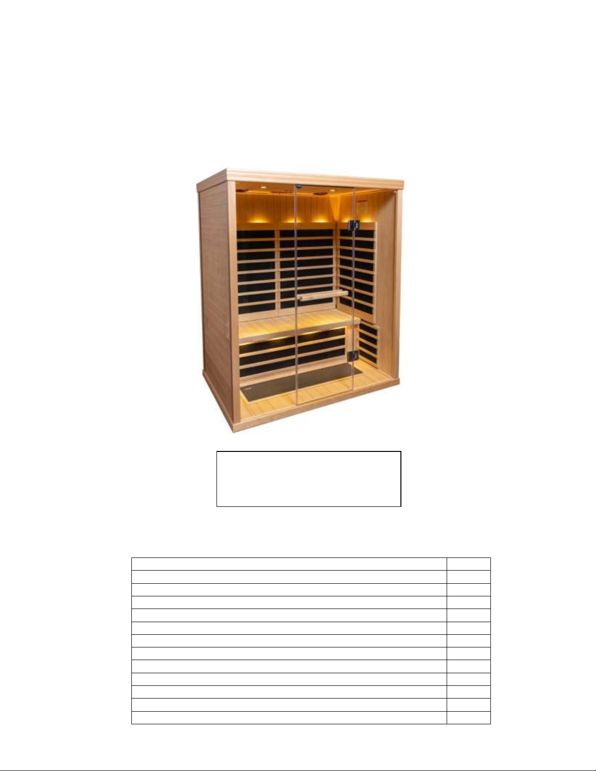
S3-Series
2 Person Infrared Sauna
Touch Pad and Bluetooth
IG-825-SH/S825
User Manual
Note: Room must be installed on flat, level surface.
710-0126 IG-825-SH / S825-H 2 Person IR Sauna Page 1 04/09/14
Ver. 3 Rev. 4

Precautions before Use: Warning (Room Configuration & Use):
Proper Electrical Grounding is Required
Electrical Receptacles not Allowed in the Room
Do not Apply Water to any Heating Element
Do not Add a Locking or Latching System to the Door
Do not Block Ventilation Openings
Children Must be Supervised at all Times in the Sauna
NOTE: A GFCI (Ground Fault Interrupt Circuit) device is not required by NEC. A
GFCI may be installed if required by local codes but will nuisance trip during use of
the product. - CAUTION: Loose wire connections can cause heat damage to wires,
terminal blocks and other components and may void the warranty.
Electrical Caution – Do not plug the room power cord into an electrical outlet until Room Assembly
is completed!
a. Warning (Human Limitations):
Prolonged Exposure at Elevated Temperatures May Cause Hyperthermia (Body Temperature is Several
Degrees Above 98.6F)
Hyperthermia Symptoms include: Dizziness, Lethargy, Drowsiness, and Fainting
Hyperthermia can cause:
Fetal Damage in Pregnant Women
Physical In-Ability to Exit the Room
Loss of Consciousness
Notice - Use of Alcohol or Drugs Increases the Risk of Fatal Hyperthermia
If You Have any Health Problems or Health Conditions, Consult Your Physician Prior to Sauna Us,
Discontinue Use if Nervousness, Tremor, Headache, Feeling of Sickness or Nausea Occurs
b. Warning (Fire Hazards):
Do Not Use the Sauna Room for Drying Cloths, Bathing Suits, Etc.
Do Not Hang Towels or Other Objects on Heater Grills
Never Operate this Sauna Room if it Has a Damaged Cord or Plug
Pre-assembly Information:
a. Two (2) adults are required for the assembly and installation of the room.
b. Assembly Tools: Phillips Screw Driver
c. Boxes are labeled in the order of room assembly
d. Note: Front wall glass assembly is heavy and fragile.
Box #1: Floor, Ceiling, Bench Skirt, Bench, Manual & Deluxe Door Handle Set
Box #2: Left & Right Walls
Box #3: Front & Back Walls
710-0126 IG-825-SH / S825-H 2 Person IR Sauna Page 2 04/09/14
Ver. 3 Rev. 4
Electrical Requirements: The IR Sauna Room is designed for a 120 Volt AC / 15 or 20
IG 810SH
15 Amp
IG 820SH
15 Amp
IG 825SH
20 Amp
IG 830SH
20 Amp
IG 840SH
20 Amp
IG 870SH
15 Amp
IG 880SH
20 Amp
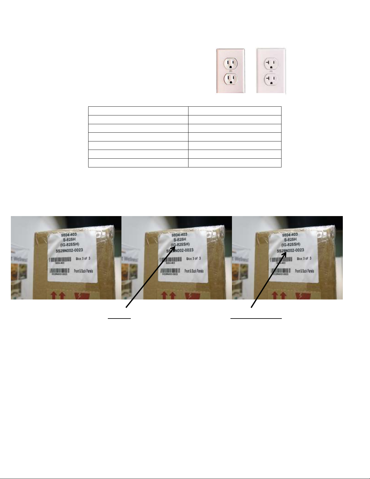
5-15R 5-20R
Amp Circuit Breaker!
A 120 Volt AC (dedicated) circuit is recommended to avoid unnecessary tripping of the breaker.
The Sauna should be plugged into a NEMA (5-15R or 5-20R)
Amp electrical outlet.
Box label will indicate the model of the room and the room serial number, the label will also
give you the box number and the internal contents.
Record your model number and serial number from box in the event you should need to
contact your dealer or technical support.
Serial Number ______________________________
Model Number ______________________________
Dealer Name________________________________
710-0126 IG-825-SH / S825-H 2 Person IR Sauna Page 3 04/09/14
Ver. 3 Rev. 4
Sauna Assembly Instructions
_________________________________________________________________________
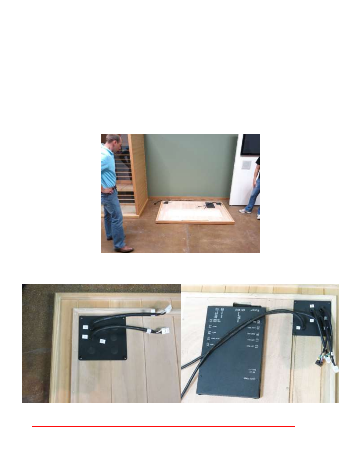
Floor Panel (Box #1):
Locate the Floor Panel on a level surface (3-6) inches from wall and no more than (5 ft) from
120 Volt AC / 20 amp dedicated receptacle.
Position the Floor panel so that the Ceramic tiles / IR Floor Heaters are to the front of the room
Note: place the Ceiling, Bench Skirt and Bench to the side until the appropriate steps.
Note: place the power cord on the ground to the side of the floor; be sure that all wires and
connectors on the sauna floor are clear of the slots.
Note – Do NOT Plug the Sauna Room 120 VAC Power Cord into the Outlet Yet!
710-0126 IG-825-SH / S825-H 2 Person IR Sauna Page 4 04/09/14
Ver. 3 Rev. 4

Back Wall (Box #3):
Note: after opening box 3 -- store Front Wall panel until that step of the assembly process.
Be sure to control the door from opening when moving the Front Wall Panel to prevent breakage.
Place Back Wall panel into the back slot of the Floor Panel.
Back Wall panel must be held in place until the Right Wall panel is added.
710-0126 IG-825-SH / S825-H 2 Person IR Sauna Page 5 04/09/14
Ver. 3 Rev. 4
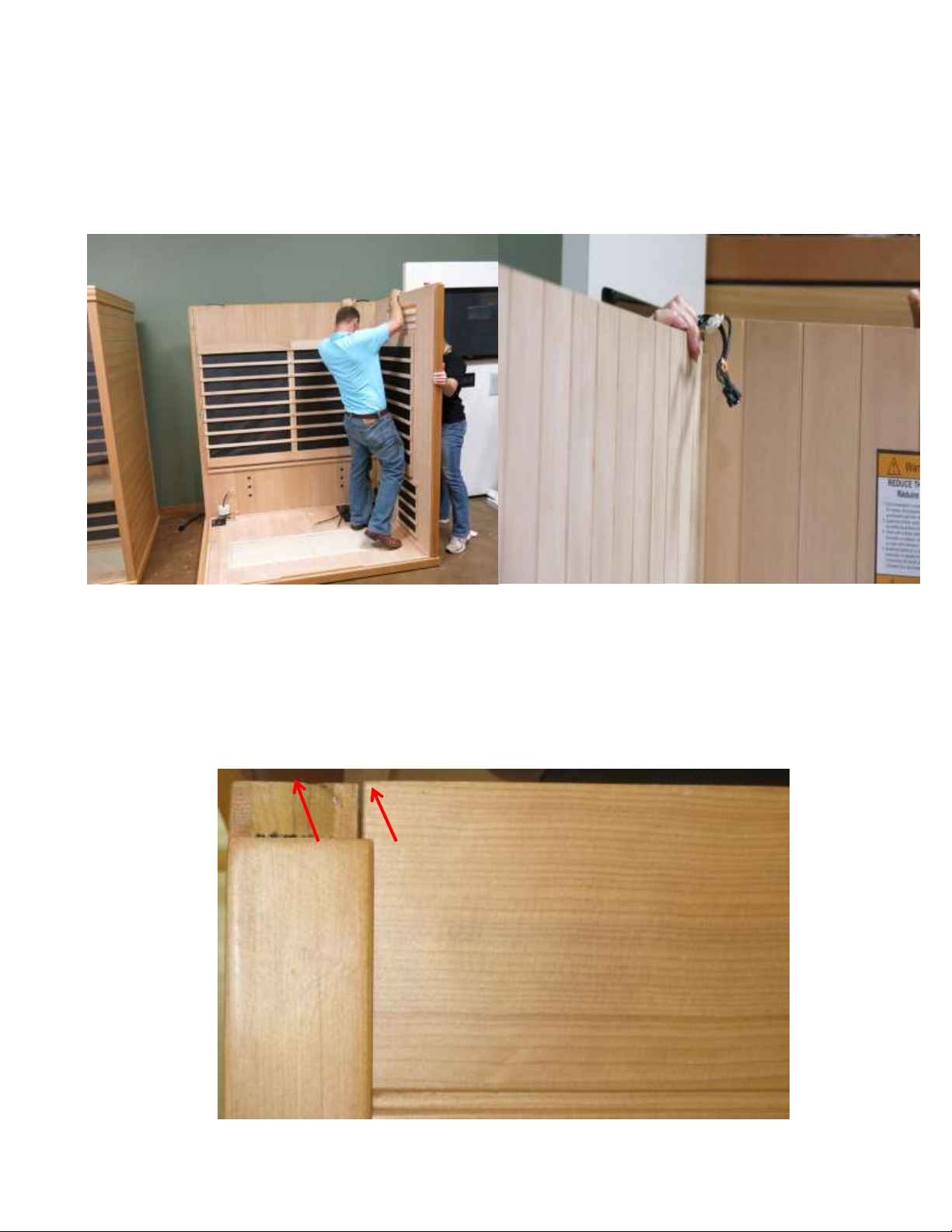
Right Wall (Box #2):
Place Right Wall section into the right slot of the Floor Panel.
Attach Back Wall to the Right Wall by lifting up the Right wall sliding into the corner interlock
brackets.
Left Wall (Box #2):
Place Left Wall section into the left slot of the Floor Panel.
Attach the Back Wall to the Left Wall by lifting up the left wall sliding into the corner interlock
brackets.
Note: When wall panels are connected in place properly the corners will be level and flush on top.
710-0126 IG-825-SH / S825-H 2 Person IR Sauna Page 6 04/09/14
Ver. 3 Rev. 4
 Loading...