

Installation & Operation Instructions
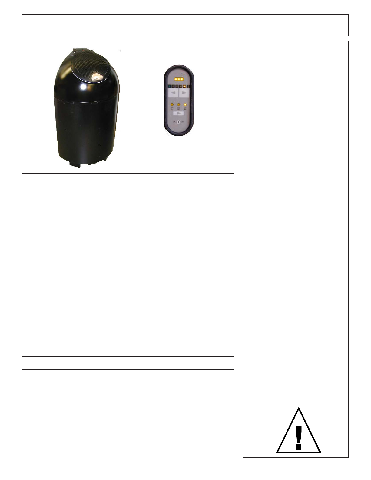
SAUNA HEATER 1108-24, 1108-46 & 1108-60
Saunatonttu 2.4, 4.6, & 6.0 kW
Read all instructions carefully before installation.
Please leave all instructions with the owner.
1
Warning
Do not take a sauna if using
alcohol, drugs or medications.
Pregnant women or persons
with poor health should
consult their physician before
using any sauna.
Caution fire hazard: Do not
use the sauna room for drying
clothes, bathing suits, etc. Do
not hang towels above heater
or place any object, other than
the rocks supplied, on the
heater. If any darkening of
the wall around the heater is
noticed discontinue sauna use
immediately.
WARNING
Prolonged exposure to elevated temperatures is capable of inducing
hyperthermia. Hyperthermia occurs when the internal temperature of
the body reaches several degrees above the normal body temperature
of 98.6°F. The symptoms of hyperthermia include an increase in the
normal temperature of the body, dizziness, lethargy, drowsiness, and
fainting. The effects of the hyperthermia include failure to perceive
heat, failure to recognize the need to exit the room, unawareness of
impending hazard, fetal damage in pregnant women, physical inability
to exit the room and unconsciousness.
WARNING
The use of alcohol, drugs, or medication is capable of greatly increasing the risk of fatal hyperthermia.
SECTION 1: GENERAL INFORMATION
Note: Saunatonttu users: Please read “Section 6” to understand the
principles around which this heater is designed, and to understand the
sauna conditions it will create for you.
Inspect sauna regularly for
required maintenance to
heater, control and benches.
Replace wood surfaces which
show any signs of deteriora-
tion.
The heater opening gets
extremely hot during opera-
tion.
Keep clear of opening while
sprinkling water on the rocks.
Steam is very hot and forceful.
Close heater lid after use.
Minors should be adequately
supervised whenever near a
hot or warming sauna.
These heaters are UL approved for permanent installations and electrical
connections. Built with splash proof construction, the conducting parts
are protected against water. All wiring must be performed in accordance
with local codes. See Diagram 2 for wiring and room size requirements.
4211-86-G 09-23-05
314 SKLH 20C
Installation & Operation Instructions
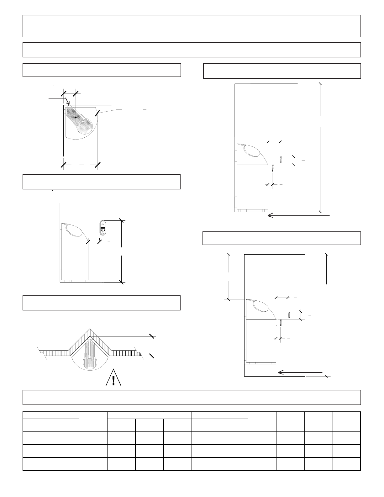
DIAGRAM 1
2
High
Limit
Reset
Button
DIAGRAM 1A
7" From the corner to screw hole
3
"
4
19
16
Rad. 12
11
"
DIAGRAM 1B
Securing of the control in the
sauna room.
control
1
1
"min.
4
45"max.
DIAGRAM 1D
1
1
" Min.
4
5
1
" Min.
2
DIAGRAM 1E
1
" Max.
2
81" min.
On/Off
Switch
DIAGRAM 1C
Example of an installation in depression of a wall.
13"
OBSERVING MINIMUM DISTANCES IS
REQUIRED TO AVOID FIRE HAZARD
HEATER
MODEL TYPE Floor Area
Saunatonttu
2.4
Saunatonttu
4.6
Saunatonttu
6.0
1108-24 2.4 12 sq. ft. 81" 100 96" 210 1 240 10.0 12-2 W/G
1108-46 4.6 21 sq. ft. 81" 175 96" 310 1 240 19.2 10-2 W/G
1108-60 6.0 31 sq. ft. 81" 250 96" 425 1 240 25.0 10-2 W/G
kW
MINIMUM ROOM
Ceiling
Height
30" min.
Note: Raised platform
must withstand 350 lbs
of weight!
DIAGRAM 2
MAXIMUM ROOM
Vo lum e
Cu.Ft .
Ceiling
Height
Vo lum e
Cu.Ft .
1
1
" Min.
2
1
" Min.
4
5
1
" Max.
2
AMP SVA CPhase
81" min.
platform
Wire Size
4211-86-G 09-23-05
314 SKLH 20C
Installation & Operation Instructions
3
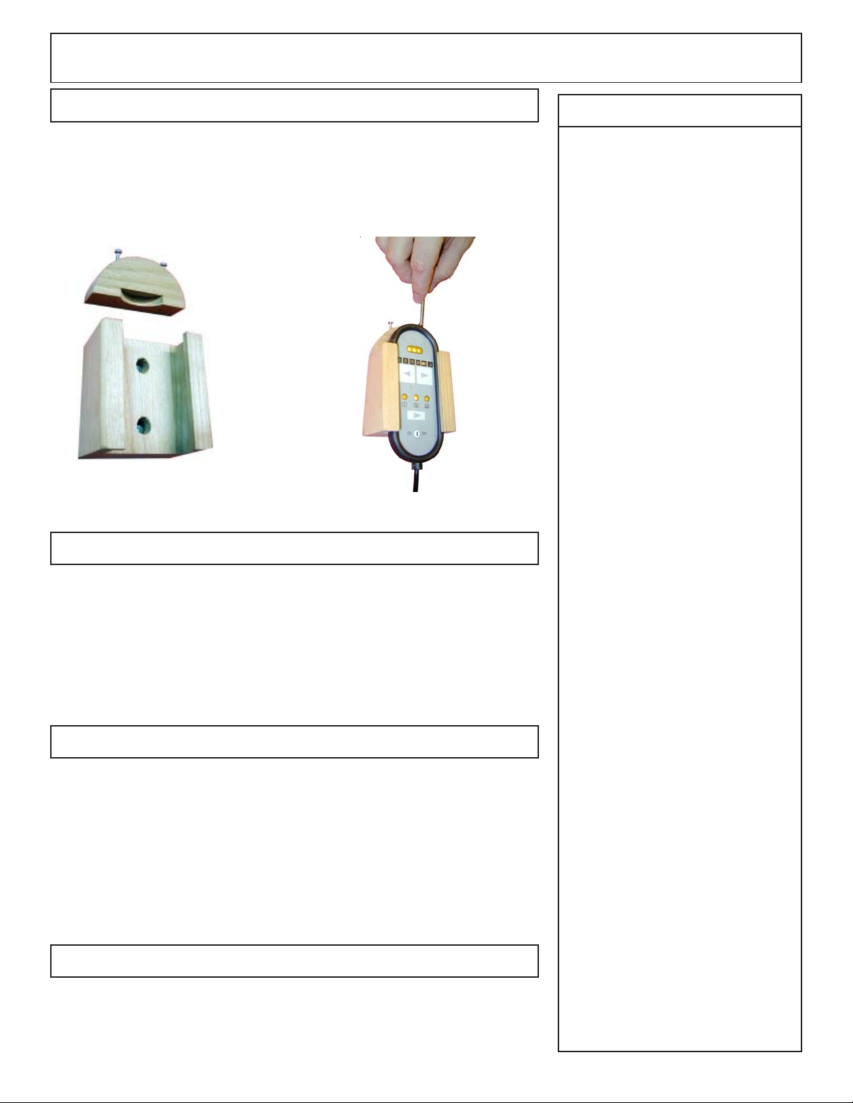
SECTION 2: MOUNTING SAUNA HEATER AND CONTROL
Carefully locate the heater according to the dimensions shown in Diagram 1.
The supplied mounting block and control must be located and mounted
according to Diagram 1B. (This is to prevent the control from being placed in
an unsafe location.)
SECTION 3: PLACING OF ROCKS
The rocks supplied with the heater have been chosen to provide the best
heater performance. Use of any other type of rock may void the heater’s
warranty. Never operate the heater without rocks in place! Rinse the
rocks with water before placing in the heater. Place the rocks loosely to
keep the elements vertical and so the air can circulate through the heater.
Packing the rocks too tightly may cause the heater high limit switch to
trip. The rocks must fully cover the heating elements.
SECTION 4: ELECTRICAL HOOK-UP
Warning
Fire sprinkler systems used
inside any sauna room
should be properly rated for
sauna room temperatures.
Do not pour chlorinated
pool or spa water on heater.
Excessive water use on
heater may cause damage
and void warranty.
Do not install a shower in
the sauna room.
Electric Shock Hazard -
High voltage exists within
this equipment. There are
no user serviceable parts in
this equipment. All installa-
tion and service to this
equipment should be per-
formed by qualified licensed
personnel in accordance
with local and national
codes.
Do not construct sauna
room so as to restrict air
flow through the bottom of
the heater.
Electrical installation must be made by a licensed electrician in accordance with the National Electrical Code and local regulations.
To determine the correct wire size, refer to Diagram 2. Use copper
supply wire only, suitable for minimum 90 degrees C. The heater must
be grounded! See the heater wiring diagrams for proper connections.
Remove screws from the back cover to gain electrical access. Refer to
Diagram 10.
SECTION 5: GUARD RAIL
To reduce the risk of injury (hot surface of sauna heater opening) install
the heater guard rail with the clearances and dimensions shown in
Diagram 1.
4211-86-G 09-23-05
Packing the rocks too tightly
may cause the heater high
limit switch to trip.
314 SKLH 20C
Installation & Operation Instructions
4
SECTION 6: THEORY of OPERATION
This heater is always ready and is designed to keep the rocks in the rock
chamber hot at all times using a “Continuous Power” setting of 100 Watts, 200
Watts or 300 Watts. This amount of energy is stored and accumulates in the
rocks while the lid is closed.
First time use or with rocks cold:
With the lid closed, turn the system on by pressing the Reset button on the
control. Next press the upper “>” right arrow until the 60 minute indicator
glows. The sauna heater will be close to operational temperatures in 1 hour.
Refer to Diagram 4 for Control Discription.
Normal Use:
Rocks are hot and lid is closed. Open the lid to allow the energy to transfer into
the room. Leave room and return in 5-10 minutes. The room temperature should
be 125 F - 135 F. Now the sauna is ready to use.
Sprinkle the water on as desired to personal preferences of temperature and
humidity. Wait a few seconds and add another ladle of water on rocks. The
humidity in the air will rise and make the room feel hot. Continue to add water
as desired. The room temperature will also rise. If air becomes uncomfortable,
close the lid and this will remove the heat source.
Warning
Minimum clearance from
heater to wooden surfaces
(benches, side walls,
heater fence etc.) is shown
in diagram 1.
Use only copper wire of
the size and type indicated
in the Heater Specifica-
tion Chart and the tem-
perature rating indicated
on the heater junction
box.
All heaters and controls
must be grounded per
NEC to prevent electrical
shock in case of unit
failure.
This heater is designed to have the lid open for a maximum of 60 minutes
for any sauna bath.
The steam is very hot and forceful. Please stay clear of opening while
sprinkling water on the rocks.
After sauna bath, the lid should be closed to allow the Continuous Power to
replenish the rock temperatures.
Tips: Continuous Power settings vs. time to replenish rock temperatures:
Use sauna 4 - 5 times a week, set on 300 W
Use sauna 2 - 3 times a week, set on 200 W
Use sauna 1 time a week, set on 100 W
Turn on Boost Power if lid will be open longer than 30 minutes during 1 session.
This will keep rocks hot to create steam.
Note: Sauna temperatures are typically measured one foot from the ceiling. The
Saunatonttu is designed to operate between 130 and 150 degrees F, although it
can achieve higher temperatures if allowed to heat with the lid open for an hour.
Electrical outlets or
receptacles must not be
installed in a sauna room.
A guardrail or fence is
required around the
heater to prevent burns
from accidental contact.
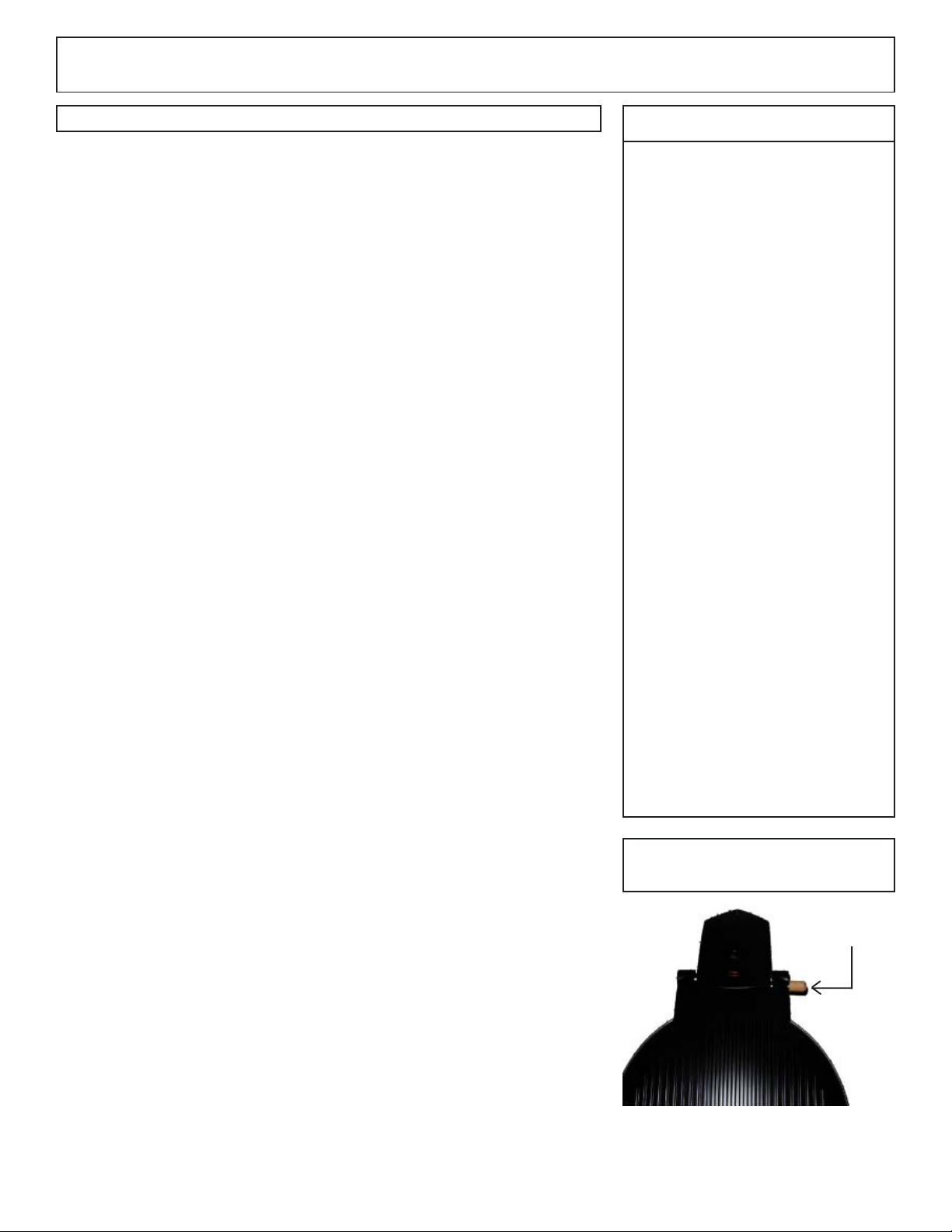
Safety Locking Lid
Locking Pin
Safety Locking Lid:
On the right hand side of the lid, there is pin with a wood knob. To release the lock, pull out on wood pin.
This will allow the lid to be moved. There are two locking positions, full open or closed.
4211-86-G 09-23-05
314 SKLH 20C

Installation & Operation Instructions
F
5
SECTION 6: THEORY of OPERATION CONT.
Sauna Temperature and Humidity Theory:
The worldwide trend in sauna bathing is “lower temperatures and higher humidity”—much like ancient
woodburning saunas. Old woodburning saunas (ancient “smoke saunas” or more recent saunas with
woodburning stoves) had massive amounts of rocks, heated by burning wood, which in turn created a soft
radiating heat, and very pleasant steam when water was sprinkled on the rocks. The Saunatonttu captures the
essence of those wonderful saunas of old.
A large rock mass is the essential feature to create lower temperature/higher humidity saunas. The Saunatonttu’s
combination of 200 pounds of rocks surrounded by high-tech super-insulation makes it possible. The large rock
mass, superheated with minimal energy, is ready for sauna with the simple opening of the lid. Soft heat and
wonderful steam are immediate.
This large rock mass concept is based on the “Rule of 200” (see Diagram 3) which illustrates how humidity and
temperature interact. The “Rule of 200” suggests: “To the typical sauna bather, a sauna is most comfortable
when the combination of degrees Fahrenheit plus Relative Humidity is 200 or less”.
Example: Room temperature is 145 F. 200 - 145 = 55
There could be up to 55% humidity in the room before it becomes uncomfortable for the user. If temperature
goes up the humidity level will need to come down to be comfortable for the user.
DIAGRAM 3
Rule of 200
TM
190
180
170
160
150
140
Temperature
130
120
4211-86-G 09-23-05
110
100
90
10
20
0
3
0
4
0
5
% of Humidity
0
6
70
80
90
0
0
1
314 SKLH 20C

Installation & Operation Instructions
6
SECTION 7: OPERATION
For health and fire safety, never attempt to alter or bypass the controls.
This heater has a 60 minutes timer built into the programming. The rock
temperature is preset by the manufacture.
Turning system on:
Position the O - I (On/Off) rocker switch on the lower front of heater to
the “Up” position. This switch can remain in the “I or On” position
indefinitely. The “I” position puts the hand held control in the standby
mode.
Control button names are listed in Diagram 4.
Initializing System: Press the “Reset” two or three times to cycle the
control until the “0” is the only thing glowing in the Boost Power Time
Indicator Lights. This means that the “Boost Power” is set for “0” minutes and the “Continuous Power” is “Off”. Press the “Reset” button
again and the control will be in the Standby mode.
To activate “Continuous Power” press the Continuous Power Arrow
“>” on lower half of control. Pressing this button will cycle through the
Continuous Power settings from 100 Watts to 200 Watts and then to 300
Watts. Press the button again and it will turn them off.
Diagram 4
A
B
D
C
F
E
G
H
I
Reset
A Boost Power On Lights
B Boost Power Time Indicator Lights
C Increase Boost Power Time Arrow
D Decrease Boost Power Time Arrow
E 100 Watt Indicator Light
F 200 Watt Indicator Light
G 300 Watt Indicator Light
H Continuous Power Arrow
I Reset Button
The “Continuous Power” is used to replenish the rock temperatures during non sauna use. The lid should be
closed and the heater would use the chosen Continuous Power setting to heat the rocks to normal operating
temperature and the internal thermostat would regulate the temperature. The higher the Continuous Power
setting, the quicker the rocks would regain temperature and be ready to be used again. Refer to “Tips” in Section
6 for more information.
To activate the “Boost Power” press the arrow keys at the top of control to activate the Boost Power timer. As
the arrow “>” key is pressed the time will increase to a maximum of 60 minutes. Press the “<” arrow key and
the time will decrease until 0 minutes.
To activate the “Closed Lid Power” press the “<“ arrow key at the top of the control until the green light is
glowing. This mode will reduce maximum power to continuous power after 3 to 10 minutes when the lid is
closed. When the lid is open, the maximum power will turn back on after 3 to 10 minutes.
The “Boost Power or Closed Lid Power” provide maximum power to the rocks with a maximum time of 60
minutes.
Note: No control functions will be glowing in the Standby mode.
4211-86-G 09-23-05
314 SKLH 20C

Installation & Operation Instructions
DIAGRAM 5
SINGLE PHASE WIRING DIAGRAM: Saunatonttu 6.0 kW heater
Heater Type: 1108-60
7
4211-86-G 09-23-05
314 SKLH 20C

Installation & Operation Instructions
DIAGRAM 6
SINGLE PHASE WIRING DIAGRAM: Saunatonttu 4.6 kW heater
Heater Type: 1108-46
8
4211-86-G 09-23-05
314 SKLH 20C

Installation & Operation Instructions
DIAGRAM 7
SINGLE PHASE WIRING DIAGRAM: Saunatonttu 2.4 kW heater
Heater Type: 1108-24
9
4211-86-G 09-23-05
314 SKLH 20C

Installation & Operation Instructions
DIAGRAM 8 DIAGRAM 9
Exhaust
10
DIAGRAM 10
Fresh Air
Electrical access for the heater is on
the back of the heater.
4211-86-G 09-23-05
314 SKLH 20C

Installation & Operation Instructions
11
SECTION 8 : WARNING PLACARDS
Three metal placards are included in the Installation Instruction Envelope packaged with the Saunatonttu Heater.
The CAUTION placard must be attached to the interior wall of the sauna
room directly above the heater where it is visible to the bather.
The WARNING placard must be attached to the door of the sauna room.
The placard for lid closer must be attached just below the “Caution”
placard in the room above the heater.
SECTION 9 : ROOM CONSTRUCTION
For safety and reliability, the following rules must be addressed.
• No permanent locking or latch system can be used on the sauna door.
• Acceptable door fittings are: magnetic catches, friction catches,
spring or gravity loaded closures. The door must always open
outwards.
• No shower can be installed in a sauna room.
• No electrical receptacle shall be installed inside the sauna room.
• The enclosed WARNING: Reduce the risk of overheating …the
warning plate must be mounted on or alongside the door outside the
sauna room at about eye level.
• The enclosed CAUTION: Reduce the risk of fire … the caution plate
must be mounted on the interior wall above the heater.
• The heater must not be operated without its container properly filled
with rocks and the rock guard in place.
• If an intercom speaker is installed, it should be away from the heater
and as close to the floor as possible.
• If a room light is installed, it should be a surface mounted bracket
type. Wall mounted lights should be about 70" above the floor.
Ceiling mounted lights should be an approved type with a junction
box that is remote to the fixture itself. Use only a fixture that uses
A.F. or fixture type internal wiring. A 60 watt bulb should provide
sufficient lighting.
• Fire sprinkler systems installed inside any sauna room should be
properly rated for sauna room temperatures.
• Always mount the heater according to these installation instructions.
Warning
The “CAUTION” and
“WARNING” placards
must be mounted in accor-
dance with Section 8.
For safety purpose sauna
door must open out and not
lock.
Never use a wood stain,
seal or preservative on the
inside of your sauna room.
Light fixtures get very hot
during operation. Locate
light fixture where it will
not be a burn hazard.
4211-86-G 09-23-05
314 SKLH 20C

Installation & Operation Instructions
SECTION 10 : HIGH LIMIT CONTROL (RESET BUTTON)
The sauna heater has a built-in High Limit control, which automatically
turns off the heater if the temperature inside the sauna room rises to an
abnormally high level.
To reset the high limit control, let the heater cool and then push the button.
The reset button is on the back top right corner of the heater. The button is
protected by a soft rubber grommet. See Diagram 1A.
12
If the High Limit continues to shut off the heater, contact a service representative.
SECTION 11 : HOW TO TAKE A SAUNA
• When taking a sauna, allow time to relax completely.
• Remove clothing and jewelry.
• Some sauna bathers enjoy the soothing effect of steam by splashing
water on the heated sauna rocks. Use only one dipper full (approx. ½
cup) at a time and take care to keep clear of the steam as it rises off the
rocks.
• After 10 minutes or when perspiring freely, leave sauna and relax in the
dressing area, followed with a warm shower.
• Enter sauna room again when ready and stay 5 or 10 minutes.
Shower
Sauna (10-15 min)
Rest (10-15 min)
Relax with juice or water
• Repeat the cycle 2 or 3 times; end with a warm shower and rinse in
cool water.
• Dress when completely dry and perspiration has stopped.
• Do not smoke, exercise or drink alcoholic beverages in the sauna room.
• Do not pour chlorinated pool or spa water on the heater or corrosion
damage may result.
4211-86-G 09-23-05
Like it?
Do it again and feel great.
314 SKLH 20C

Installation & Operation Instructions
SECTION 12 : VENTILATION
VENTILATION Ventilation shall be provided in a sauna, the air should be changed about 6 times an hour. This
can be achieved by making a vent opening (fresh air inlet) in the sauna wall directly below the heater. The air
outlet must be lower than the upper benches, as far as possible from the heater and about two feet higher than
the fresh air inlet vent, See Diagram 9.
The minimum opening should be determined using one of the following formulas:
For R<31, V≥9.4
For R≥31, V≥0.3R
where R = the floor area of the room in square feet and
V = the minimum vent size in square inches
SECTION 13 : MAINTENANCE
The sauna, like a bathroom, should be kept clean and odor free.
13
Towels or mats should always be used on benches and floor as perspiration otherwise penetrates the soft wood.
Air out the sauna often by keeping the door and vents open when the sauna is not in use. Saunas that are in daily use
should be washed down at least once a week to keep them clean and the air fresh. Duckboard should be removed
from the sauna, the sauna floor mopped and dried in a conventional manner, and the duckboard thoroughly scrubbed
and dried before returning to the sauna room. The sauna heater should be wiped down occasionally with a damp
cloth to remove lint and dust. The rocks should be removed once a year for cleaning and small or crumbled rocks
replaced.
To clean and remove perspiration stains, use soap or detergent in warm water, best applied with a scrub brush.
Badly soiled surfaces may require sanding. Sand paper wrapped around a wooden block works well.
Benches and supporting structure must be inspected annually for potential deterioration due to age, dry rot or
abuse. Any boards with signs of deterioration should be replaced immediately to avoid possible injury.
SECTION 14 : TROUBLESHOOTING
For troubleshooting or service questions call 1-888-780-4427 and ask to speak with service. Also contact the
following e-mail addresses for sales or technical support.
sales@saunatec.com
techsupport@saunatec.com
4211-86-G 09-23-05
314 SKLH 20C
 Loading...