

Page 1
Si-83
EN
FR
IT
ES
DE
NL
RU
N960/01 Edition 22/39
Certied
Management System
Page 2
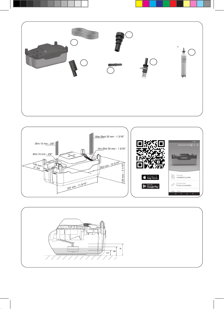
Fig. 1
A
ACC00911
Ø 10 mm int - 25 m
Ø int 3/8’’- 82’
B
ACC00939
Ø 15/17 - 20 - 24/25 - 32 - 40 mm
Ø int 5/8’’- 3/4’’- 1’’- 1 1/4’’ - 1 1/2’’
F
C
ACC00908
Ø 10 - 20 mm
Ø 3/8’’ - 3/4’’
SI83CE01UN23 - SI83CE41UN23 - SI83CE71UN23 SI83CE04UN23 - SI83CE74UN23 : E
SI83CE02UN23 - SI83CE42UN23 : A, B
SI83CE43UN23 : A, B, F
SI83CE05UN23 : A, C, D
SI83CE07UN23: A, C, D
Fig. 2
E
Ø 10 - 10 mm
D
Ø 3/8’’ - 3/8’’
SI83UL02UN12 - SI83UL42UN12 - SI83UL72UN12 SI83UL02UN23 - SI83UL42UN23 - SI83UL72UN23 : B
SI83UL03UN12 - SI83UL03UN23 : A, B
6 mm (1/4’’)
App.
Si-83 mobile App
PH0100SIUN23
Fig. 3
Google Play and the Google Play logo are trademarks of Google LLC.
App Store is a service mark of Apple Inc.
2
AL *: 48 mm (1 7/8’’)
OFF : 21 mm (0 13/16’’)
ON : 40 mm (1 9/16’’)
Page 3
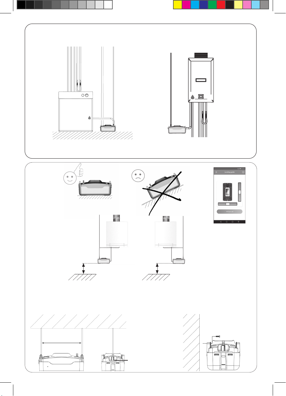
Fig. 4
Fig. 5
pH ≤ 3
+ pH Safe 1,
ref : PH0100SIUN23
A.
B.
262 mm - 10 5/16’’
> 20 cm > 20 cm
M6 max.
Max 15°
C.
3
Page 4
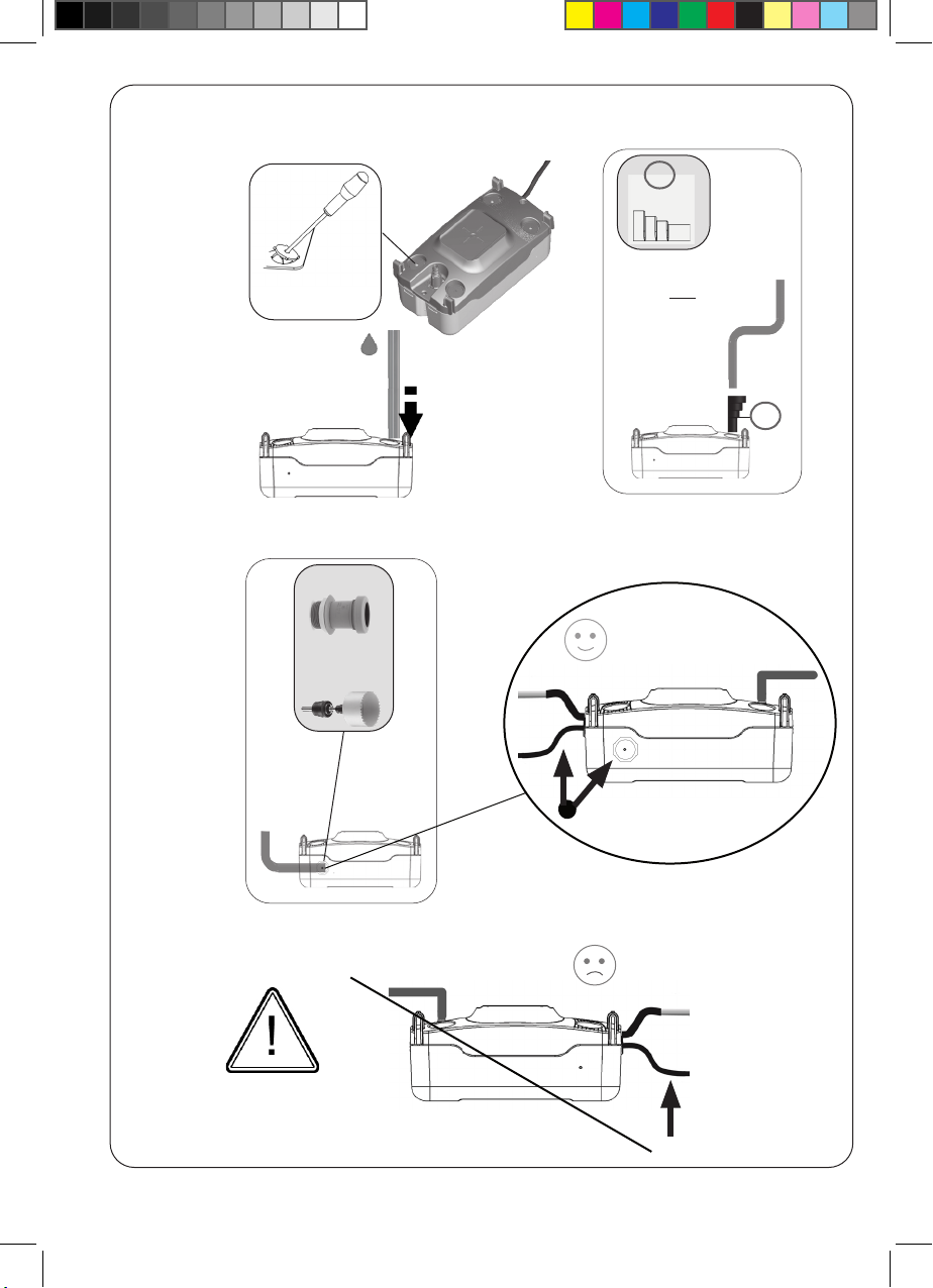
Fig. 6
A.
B.
Ø 30 mm
Ø 1 3/16 ’’
ACC00940
Ø 42-46 mm
B
ACC00939
Ø 40 mm, 1 1/2’’
Ø 32 mm, 1 1/4’’
Ø 24 - 25 mm, 1’’
Ø 20 mm, 3/4’’
IN
Ø 15 - 17 mm, 5/8’’
B
+
4
Page 5
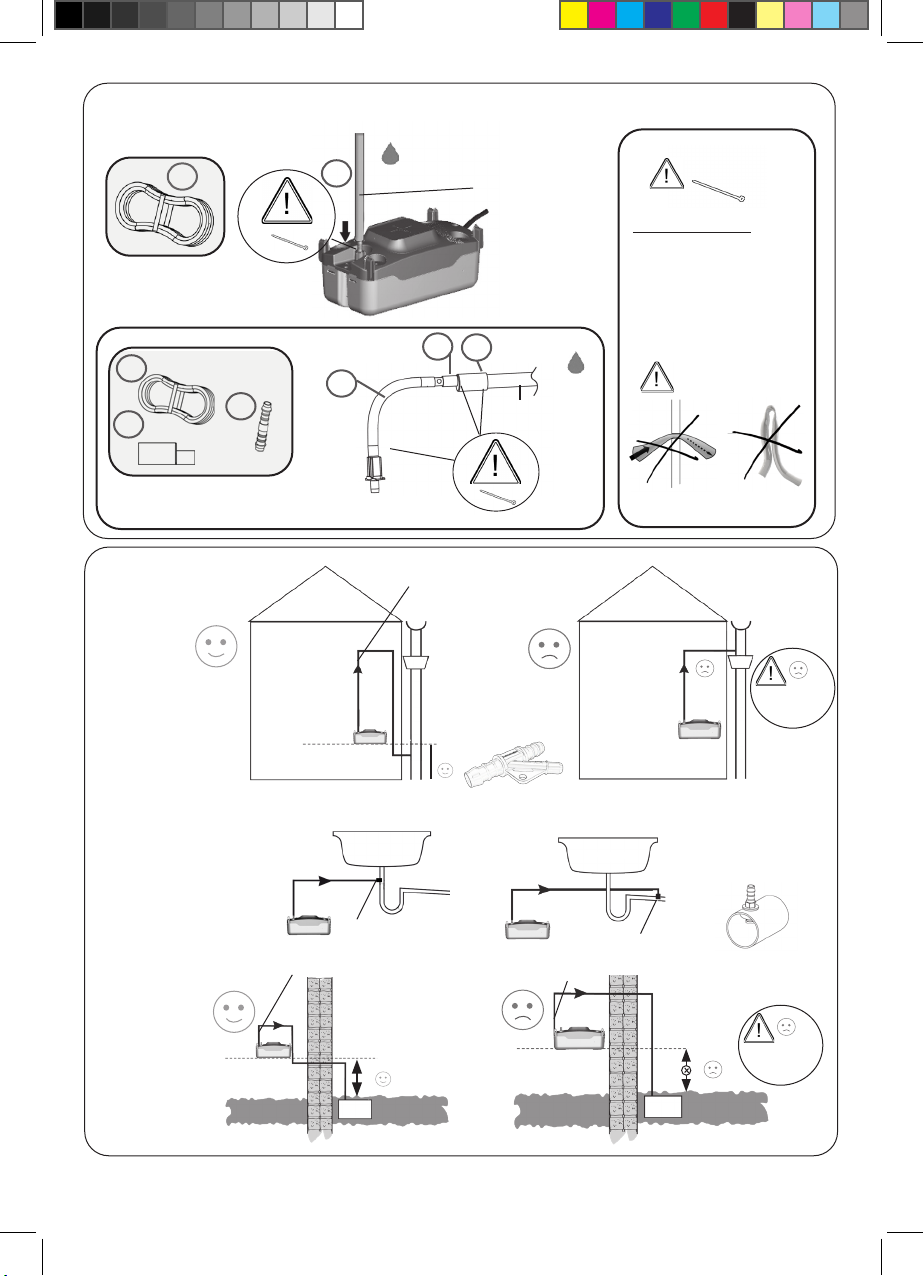
Fig. 7
A.
A
A
OUT
Ø 10 mm int.
Ø 3/8 ’’
* PLEASE NOTE *
ALL PIPE CONNECTIONS
MUST BE SECURED WITH
A TIE WRAP/METAL CLIP
(ACC00913)
B.
A
C
Fig. 8
A.
B.
D
C
A
D
Use a tie wrap or metal clip (ACC00913)
ACC00923
ACC00923
Ø 20 mm
Ø 3/4 ’’
OUT
ACC00920
c
< 0°C
< 32°F
C.
ACC00923
ACC00920
ACC00923
ACC00920
c
< 0°C
< 32°F
5
Page 6
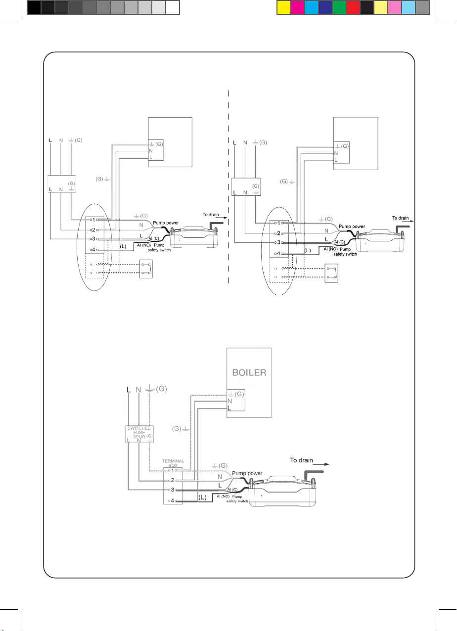
Fig. 9
NO
NC
NC
6
Page 7
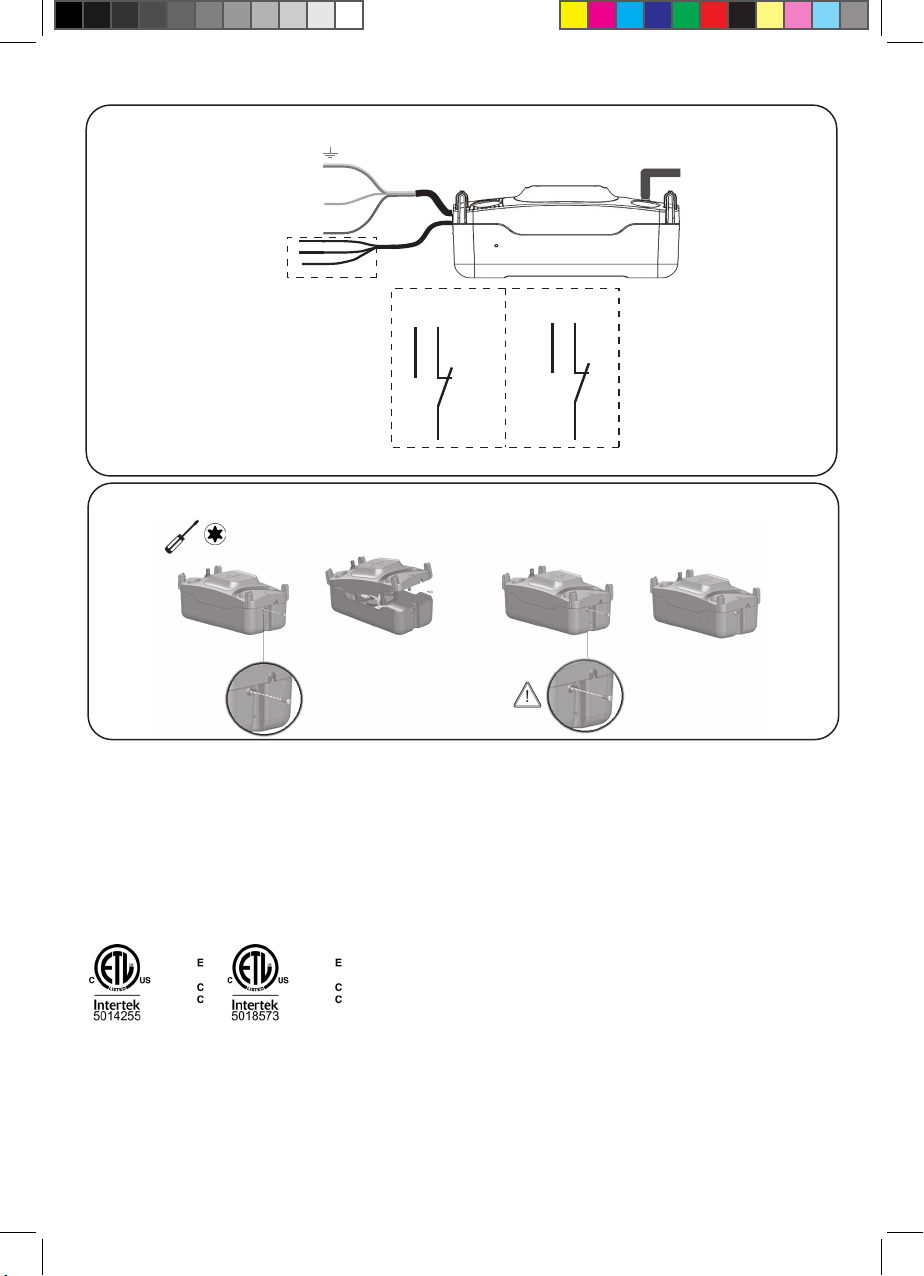
L
N
(G)
Al (C)
Al (NC)
Pump power
Pump
safety switch
Al (NO)
Black
Red
Al (C)
Grey
Al (C)
Grey
Al (NC)
Al (NO)
Fig. 9 bis
Fig. 10
NC/NO
T10
CERTIFICAT DE CONFORMITE / CONFORMITY CERTIFICATE / BEREINSTIMMUNGSBESCHEINIGUNG / CERTIFICATO DI CONFORMITA
SAUERMANN - Z.I l’orée de Chevry - 77173 CHEVRY COSSIGNY - FRANCE
- déclare que le produit pompe de relevage de condensats Si-83 est conforme aux normes :
- declares that the product Si-83 condensate lift pump is in conformity with the standar :
- erklärt, dass das Produkt, Kondensatförderpumpe Si-83 den fogenden Normen entspricht :
- dichiara che il prodotto pompa elevatrice di condensa Si-83 conforme alle norme :
EN 60335-1
EN 60335-2-41
EN 55014-1, EN 55014-2
EN 61000-3-2, EN 61000-3-3
EN 62233:2008
- Nous vous rappelons qu’il est interdit de mettre en service la pompe avant que la machine dans laquelle elle est incorporée n’ait été
déclarée conforme aux dispositions de la directive machine 2014/35/EU et de la directive compatibilité électromagnétique 2014/30/EU
- Please note that it is prohibited to put this pump into service before the machine in which it is incorporated has been declared to conform
with the provisions of machine directive 2014/35/EU and with the electromagnetic compatibility directive 2014/30/EU
- Wir weisen darauf hin, daß es untersagt ist, die Pumpe in Betrieb zu nehmen, bevor die Maschine, in die sie integriert ist, den Bestimmungen
Motor-Operated Water Pumps [UL 778:2016 Ed.6+R:20Oct2017]
Liquid Pumps [CSA C22.2#108:2014 Ed.5]
der Maschinenrichtlinie 2014/35/EU und der elektromagnetischen Richtlinie entspricht 2014/30/EU
- Si ricorda che è vietato mettere in moto la pompa prima che la macchina nella quale essa si trova incorporata sia stata dichiarata conforme
alle disposizioni della direttiva macchina 2014/35/EU e della direttiva compatibilitá electromagnetica 2014/30/EU
Pour toute information / For further information: [email protected]
7
Page 8

EN
The Si-83 tank pump from Sauermann is perfect for residential A/C (EU: up to 20 kW, US: up to 20 kW / 60,000 BTU) and heating
units EU: (up to 40 kW, US: 73 kW / 250,000 BTU).
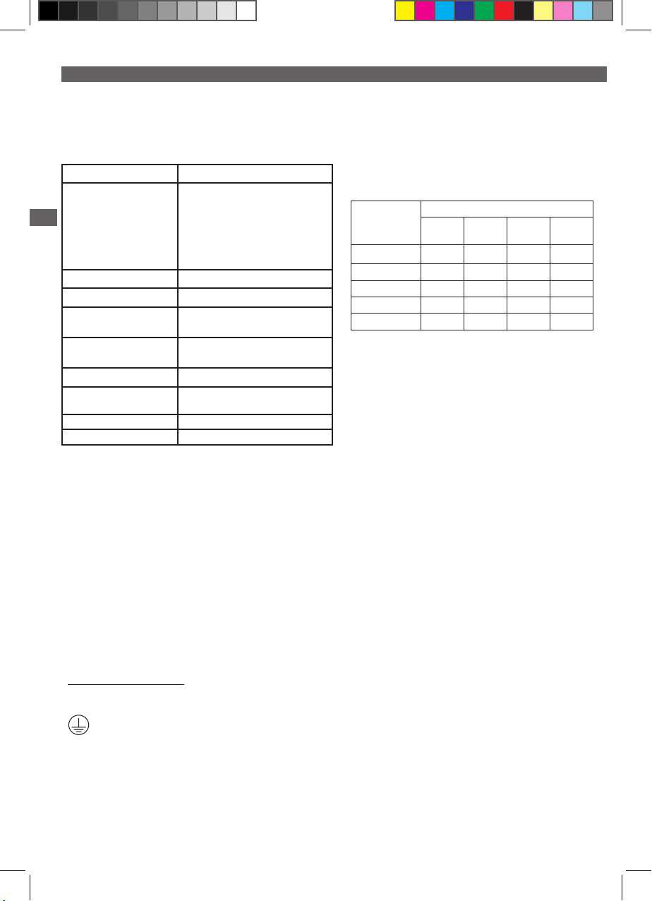
Technical features: SI83CE01UN23 - SI83CE41UN23 SI83CE71UN23 - SI83CE02UN23 - SI83CE42UN23 SI83CE42UN23 - SI83CE04UN23 - SI83CE74UN23 SI83CE05UN23 - SI83CE07UN23
EN
Mains supply
Safety switch
Max discharge head 5.4 m
Water levels (mm) Fig. 3
Sound level in application at 1m ≤ 45 dBA (Measured in Sauermann acoustic
Max. condensate temperature
& acidity
Tank capacity 2.0 l
Thermal protection (overheating) 120°C (auto-reset)
Duty cycle 7%: 16s ON - 212s OFF
Protection IP 44
Condensate inow rates (l/h)
The head losses dened in this table are calculated with a Ø 10 mm
int. hose.
Discharge
head
230V~ 50Hz - 115 W - 1.4 A
SI83CE01UN23, SI83CE02UN23,
SI83CE04UN23, SI83CE05UN23,
SI83CE07UN23: NC: 5 A resistive 250 V
SI83CE41UN23, SI83CE42UN23,
SI83CE43UN23: NO: 5 A resistive 250 V
SI83CE71UN23, SI83CE74UN23: NC/NO:
5 A resistive 250 V
lab, pump operating with water)
55°C, 80°C short peaks pH>2.5
Total tube length
5 m 10 m 20 m 30 m
1 m 26 23 17 13
2 m 22 19 14 13
3 m 19 16 11 8
4 m 13 10 7 6
5 m 8 6 4 -
WARNING
- This pump has been designed for use with water only.
Technical features: SI83UL03UN12 - SI83UL03UN23 SI83UL02UN12 - SI83UL42UN12 - SI83UL72UN12 SI83UL02UN23 - SI83UL42UN23 - SI83UL72UN23
Mains supply
Safety switch
Max discharge head
Water levels (mm)
Max. condensate temperature &
acidity
Tank capacity
Thermal protection (overheating)
Duty cycle 7%: 16s ON - 212s OFF
Protection
SI83UL03UN12, SI83UL02UN12,
SI83UL42UN12, SI83UL72UN12:
120 V~ 60 Hz - 84 W - 1.7 A
SI83UL03UN23, SI83UL02UN23,
SI83UL42UN23, SI83UL72UN23:
230 V~ 60 Hz - 126 W - 1.55 A
SI83UL03UN12, SI83UL03UN23
SI83UL02UN23, SI83UL02UN12:
NC 5 A - 42 V peak
SI83UL42UN12, SI83UL42UN23:
NO 5 A - 42 V peak
SI83UL72UN12, SI83UL72UN23:
NC/NO 5 A - 42 V peak
21’ (6.4 m)
Fig. 3
131°F (55°C), 176°F (80°C) short
peaks pH>2.5
½ gallon (2.0 l)
248°F (120°C) (auto-reset)
IP 44
Condensate inow rates (gph)
The head losses dened in this table are calculated with a Ø 3/8’’ (10 mm)
int. hose.
Discharge
head
3 ft (1 m) 7,6/9,7 6,6/7,8 4,8/5,7 3,9/4,8
7 ft (2 m) 6,4/9,1 6,3/7,5 4,5/5,4 3,8/4,5
10 ft (3 m) 6,4/8,1 5,9/7,1 4,3/4,7 3,4/4,2
13 ft (4 m) 6,1/6,3 5,6/5,8 3,8/4,1 2,9/3,7
16 ft (4.9 m) 4,6/4,7 3,8/4,2 2,8/2,9 2,1/3,5
20 ft (6 m) 2,5/3,6 2,2/2,5 1,8/1,9 1,2/1,7
Total tube length @ 120 V / 230 V
16 ft
(5 m)
30ft
(10 m)
60ft
(20 m)
- This pump has been designed for indoor use only. It must not be immersed and/or placed in areas of high humidity or where the
ambient temperature conditions are below freezing.
- The appliance is not to be used by children or persons with reduced physical, sensory or mental capabilities, or lack of experience
and knowledge, unless they have been given supervision or instruction.
- Children should be properly supervised to ensure they do not play with the appliance.
- In case of breakdown, in particular if the supply cord is damaged, it must be replaced by a Sauermann service agent or a similarly
qualied person in order to avoid any hazard.
- For models tted with a supply cord without a plug, a means for disconnection must be incorporated to the xed wiring in accordance with local wiring rules.
- The pump shall not be installed in air handling spaces (such as a plenums or the airhandling compartment of a condensing unit).
100ft
(30 m)
WARNING: Risk of electric shock. This pump is supplied with a grounding cable and a grounding attachment plug. To reduce
the risk of electric shock, ensure that the pump is connected only to a suitable grounding device.
8
Page 9

EN
1/ START UP
a/ Mains connection (Fig.9)
Connect the cable to the mains network in accordance with local wiring rules.
Identify a protective earth (ground) terminal.
b/ Safety switch connection (Fig.9)
IMPORTANT (EU): The high level safety switch comes with a dry contact rated NC at 250 V at 2 A inductive and 5 A resistive.
IMPORTANT (USA): High level safety switch comes with dry contact NC to be connected only to class 2 circuit not to exceed 42V
peak.
For a NC conguration (Fig.9), we recommend to use this contact to cutout the application, preventing condensate overow.
c/ Hydraulic connection (Fig.6-7-8)
The pump unit should be installed horizontally, where the condensate drain pipe can enter into one of the 4 Ø30 mm (1 3/16’’)
inlet holes at the top end of the pump or one side (see g 6). The discharge connection is made through the check valve, to which
a tube of Ø int.10 mm (Ø 3/8’’) should be xed. For Ø int. 6 mm (Ø1/4’’) pipe, a Ø 6 x Ø 10 mm (1/4’’ x 3/8’’) adaptor can be used.
In this case, the ow will be reduced. The acceptable curvature of the tube’s radius is 60 mm max. (2 3/8’’). To t or dismantle the
valve tube, it is preferable to withdraw the check valve beforehand. Drilling for ACC00940 (Fig.6): drill only on the mark provided
for that purpose on one side of the tank in order to avoid any detection system failure.
Please do not test continuously the pump. In case of too close operating cycles, the motor thermal protection can activate and
disable the pump during about 15 minutes.
d/ Installation / Settings (Fig.5-8)
The pump can be installed either on the ground, on a wall (xing screws provided) or hanging from the ceiling, using the xed slot
holes on the casing (to hang the pump from the ceiling it is necessary to use two threaded ro + nuts). It is possible to choose the
side of the water exit. To ensure proper ventilation of the motor, the pump must be free of any obstruction. Be careful not to bend
the exible discharge tubing. A reinforced tube can be used. For the reduction in ow due to pressure loss, consult the ow chart.
When the pump is installed with a boiler (EN12056.1, §4.5, §5.8) : discharge tubing must be resistant to acidic water (pH<6.5). Internal
discharge recommended, to avoid freezing pipes.
2/ USE
a/ Operation
Pour water into the pump. Check that the pump starts and stops once the water level begins to fall. To check the safety switch
operation, continue to pour water into the pump until the safety switch is set OFF (use a testing meter).
b/ Cleaning
The pump must be disconnected from the mains power supply before any maintenance work is carried out. The inside of the
pump should be cleaned regularly. Remove the tank and clean it with a mild cleaning solution such as water with 5% bleach (see
g 10, the upper part can remain attached to the wall during this operation). At the same time, check that the oat is clean and
free to move. Re-install the tank and re-check the operation (§ 2.a), including the start, stop and safety switch. We recommend
to clean the tank every 6 months.
3/ WARRANTY
2 years : https://sauermanngroup.com/en/warranty
EN
9
Page 10
FR
D’une grande polyvalence, la Si-83 est idéale pour les installations résidentielles de climatisation (jusqu’à 20 kW) ou de chauffage
(jusqu’à 40 kW).
Caractéristiques techniques : SI83CE01UN23 - SI83CE41UN23 - SI83CE71UN23 - SI83CE02UN23 - SI83CE42UN23
SI83CE42UN23 - SI83CE04UN23 - SI83CE74UN23 - SI83CE05UN23 - SI83CE07UN23
Alimentation électrique
Contact de sécurité
FR
Hauteur de refoulement max
Niveau de détection (mm)
Niveau sonore en application à 1m
Température maximale des
condensats et acidité
Volume du bac
Protection thermique
(surchauffe)
Cycle de fonctionnement 7% : 16s ON - 212s OFF
Protection
230V~ 50Hz - 115 W - 1.4 A
SI83CE01UN23, SI83CE02UN23,
SI83CE04UN23, SI83CE05UN23,
SI83CE07UN23 : NC : 5 A résistif 250 V
SI83CE41UN23, SI83CE42UN23,
SI83CE43UN23 : NO : 5 A résistif 250 V
SI83CE71UN23, SI83CE74UN23 : NC/
NO : 5 A résistif 250 V
5.4 m
Fig. 3
≤ 45 dBA (Mesure effectuée dans le laboratoire acoustique Sauermann, pompe en eau)
55°C, 80°C sur courtes périodes,
pH>2.5
2.0 l
120°C (auto-reset)
IP 44
Débits réels entrants (l/h)
Les pertes de charges dénies dans ce tableau sont calculées avec de
la tuyauterie exible Ø 10 mm int
Hauteur de
refoulement
Longueur totale de tuyau
5 m 10 m 20 m 30 m
1 m 26 23 17 13
2 m 22 19 14 13
3 m 19 16 11 8
4 m 13 10 7 6
5 m 8 6 4 -
AVERTISSEMENTS
- Cette pompe est prévue pour une utilisation avec de l’eau uniquement.
- La pompe est prévue pour un fonctionnement en intérieur uniquement. La pompe ne doit pas être immergée et / ou placée dans
des lieux humides et doit être tenue hors gel.
- Cet appareil n’est pas prévu pour être utilisé par des personnes (y compris les enfants) dont les capacités physiques, sensorielles ou
mentales sont réduites, ou des personnes dénuées d’expérience ou de connaissance, sauf si elles ont pu bénécier, par l’intermédiaire
d’une personne responsable de leur sécurité, d’une surveillance ou d’instructions préalables concernant l’utilisation de l’appareil.
- Il convient de surveiller les enfants pour s’assurer qu’ils ne jouent pas avec l’appareil.
- En cas de panne, et notamment si le câble d’alimentation est endommagé, toute intervention doit être réalisée par le service après
vente Sauermann ou des personnes de qualication similaire, an d’éviter tout danger.
- Pour les modèles ne comportant pas de prise électrique, un moyen de déconnexion doit être prévu sur les lignes électriques xes,
conformément aux règles d’installation.
- La pompe ne doit pas être installée dans des espaces de traitements de l’air (tels que des plénums ou un compartiment de traitement de l’air d’une unité de condensation).
AVERTISSEMENT : Risque de choc électrique. Cette pompe est équipée d’un câble de terre. An de réduire le risque de choc
électrique, vérier qu’elle est correctement reliée à un dispositif de mise à la terre.
1/ MISE EN SERVICE
a/ Raccordement au secteur (Fig 9)
Raccorder le câble d’alimentation au réseau. Respecter les règles d’installation locales.
Identie la borne de terre de protection.
b/ Raccordement électrique du contact de sécurité. (Fig 9)
IMPORTANT (EU) : pour le raccordement électrique du contact de sécurité, vous disposez d’un contact sec d’une capacité de 250 V
et d’un pouvoir de coupure de 2 A inductif et 5 A résistif.
IMPORTANT (USA) : pour le raccordement électrique du contact de sécurité vous disposez d’un contact sec devant être raccordé
uniquement à un circuit de classe 2 de tension crète < 42V.
Pour une conguration NC (Fig. 9), nous vous conseillons d’utiliser ce contact pour couper l’application en cas de risque de débordement.
10
Page 11

FR
c/ Raccordement hydraulique (Fig 6-7-8)
La pompe est placée horizontalement en dessous de l’appareil et reçoit les condensats soit par le dessus grâce à 4 orices de
Ø 30 mm (1 3/16’’) soit sur un coté (voir g 6). Le refoulement s’effectue au travers du clapet anti-retour sur lequel sera xé un
tube de Ø int. 10 mm (3/8’’) dont le rayon de courbure max admissible est de 60 mm (2 3/8’’). Pour les tubes de Ø int. 6mm (1/4’’)
utiliser l’adaptateur Ø 6 x Ø 10 mm (1/4’’ x 3/8’’). Dans ce cas le débit sera réduit. Pour monter ou démonter le tube du clapet, il
est préférable de retirer le clapet auparavant. Perçage pour ACC00940 (Fig. 6) : percer uniquement au niveau de la marque prévue
à cet effet, sur une face du bac an d’éviter tout dysfonctionnement du système de détection.
La pompe ne doit pas être testée en fonctionnement continu. En cas de cycles de fonctionnement trop rapprochés, la protection
thermique du moteur peut s’activer mettant la pompe hors service pendant 15 minutes environ.
d/ Installation / mise au point (Fig 5-8)
La pompe peut être xée contre un mur (vis de xation fournies), posée au sol ou suspendue au plafond grâce à deux pattes de
xation (pour le montage au plafond il est nécessaire d’utiliser deux tiges letées + écrous). Un espace doit être préservé autour
de la pompe pour faciliter son refroidissement. Il est possible de choisir la sortie d’eau par rapport au bac. Faire attention à ne pas
pincer les tubes de condensats. Si besoin, utiliser un tube armé. Pour la diminution de débit due aux pertes de charge, consulter
la courbe.
Dans le chauffage (EN12056.1, §4.5, §5.8): vérier que les tubes de refoulement sont résistants aux eaux acides (pH<6.5) et privilé-
gier un refoulement à l’intérieur pour prévenir le risque de gel de la tuyauterie.
2/ UTILISATION
a/ Fonctionnement
Verser de l’eau dans la pompe. Vérier que la pompe se met en marche et s’arrête lorsque le niveau d’eau est redescendu. Pour
vérier le fonctionnement du contact de sécurité, verser continuellement de l’eau dans la pompe jusqu’à ce que le contact de
sécurité se déclenche (arrêt de l’appareil, alarme sonore ou visuelle, etc.).
b/ Nettoyage
ATTENTION : pour toute intervention la pompe doit être mise hors tension.
L’intérieur de la pompe doit être nettoyé régulièrement (tous les 6 mois). Enlever le bac de la pompe et le nettoyer avec une solution
additionnée de 5 % d’eau de Javel (voir g 10, le capot peut rester xé au mur pendant cette opération). Veiller à ce que le otteur
reste propre. Remettre le bac et refaire un essai de fonctionnement de la pompe (§ 2.a) et du contact de sécurité.
3/ GARANTIE
2 ans : https://sauermann.fr/fr/garantie
FR
11
Page 12
IT
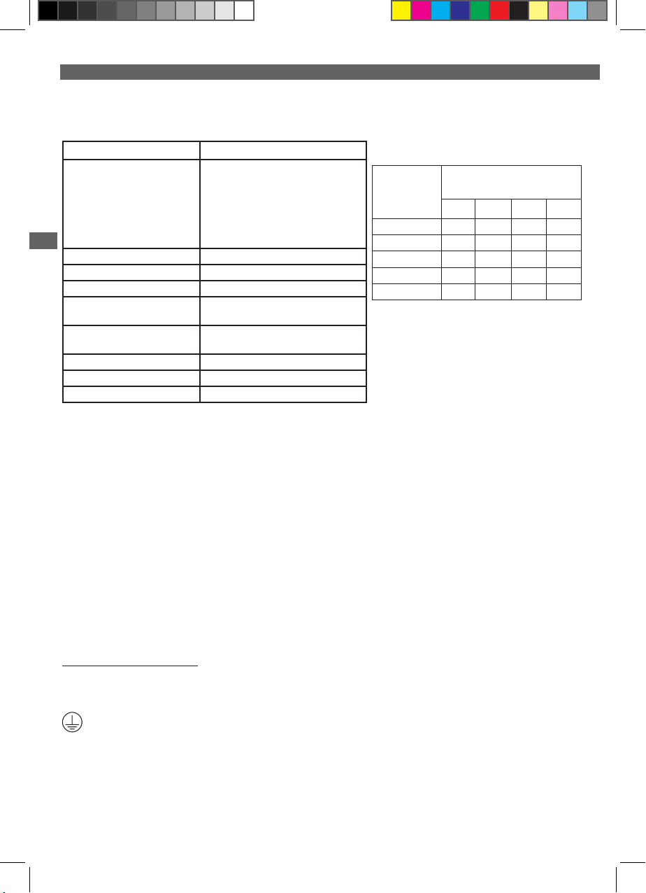
Estremamente polivalente, la Si-83 è ideale sia per impianti di condizionamento residenziale (no a 20 kW) sia per quelli di
riscaldamento (no a 40 kW).
Caratteristiche : SI83CE01UN23 - SI83CE41UN23 - SI83CE71UN23 - SI83CE02UN23 - SI83CE42UN23 - SI83CE42UN23 -
SI83CE04UN23 - SI83CE74UN23 - SI83CE05UN23 - SI83CE07UN23
Alimentazione elettrica
Contatto di sicurezza SI83CE01UN23, SI83CE02UN23,
IT
Altezza di mandata massima 5.4 m
Tipo di funzionamento 7% : 16s ON - 212s OFF
Livelli di rilevazione (mm):
Livello sonoro a 1m ≤ 45 dBA (Misurato nel laboratorio acustico
Temperatura massima delle
condense e acidità
Volume della vaschetta 2.0 l
Protezione termica 120°C (riavvio automatico)
Protezione IP 44
230V~ 50Hz - 115 W - 1.4 A
SI83CE04UN23, SI83CE05UN23,
SI83CE07UN23: NC 5 A resistivo - 250 V
SI83CE41UN23, SI83CE42UN23,
SI83CE43UN23: NO: 5 A resistivo - 250 V
SI83CE71UN23, SI83CE74UN23: NC/NO: 5
A resistivo - 250 V
Fig.3
Sauermann con pompa in acqua)
55°C (80°C - 1min)
pH>2.5
Massima portata condensa in ingresso (l/h)
Altezza della
mandata
Lunghezza complessiva della
tubazione
5 m 10 m 20 m 30 m
1 m 26 23 17 13
2 m 22 19 14 13
3 m 19 16 11 8
4 m 13 10 7 6
5 m 8 6 4 -
Le perdite di carico denite in questo schema sono calcolate con tubazione essibile da 10 mm int.
AVVERTENZE
- La presente pompa deve essere utilizzata unicamente con acqua.
- Il funzionamento della pompa è previsto esclusivamente in ambienti interni. La pompa non deve essere immersa e / o posizionata
in ambienti umidi e deve essere tenuta al riparo dal gelo.
- Il presente apparecchio non deve essere utilizzato da persone (bambini inclusi) con capacità siche, sensoriali o mentali ridotte,
o da persone prive di esperienza o conoscenza, tranne nel caso in cui abbiano potuto usufruire, tramite una persona responsabile
della loro sicurezza, di una sorveglianza o di precedenti istruzioni riguardanti l’utilizzo dell’apparecchio.
- Tenere sotto sorveglianza i bambini per accertarsi che non giochino con l’apparecchio.
- In caso di guasti, in particolare se il cavo di alimentazione è danneggiato, qualsiasi intervento deve essere effettuato dal servizio
assistenza tecnica Sauermann o da persone adeguatamente qualicate, al ne di evitare qualsiasi rischio.
- Per i modelli non dotati di presa elettrica, deve essere previsto un mezzo di scollegamento sulle linee elettriche sse, conformemente alle norme d’installazione.
- La pompa non deve essere installata negli spazi dedicati al trattamento dell’aria (quali eventuali plenum o vani per il trattamento
dell’aria di un’unità di condensazione).
AVVERTENZA: Rischio di scosse elettriche. Questa pompa è dotata di un cavo di terra. Al ne di ridurre il rischio di scosse
elettriche, vericare che tale cavo sia correttamente collegato ad un dispositivo di messa a terra.
1/ MESSA IN FUNZIONE
a/ Collegamento elettrico
Collegare il cavo di alimentazione alla rete 230V~ 50/60Hz. Rispettare le norme d’installazione locali.
Identica un terminale di terra di protezione.
b/ Conexión eléctrica del contacto de seguridad (Fig. 9)
IMPORTANTE (EU): per il collegamento elettrico dell’allarme avete a disposizione un contatto NC capacità 250 V e potere di
interruzione di 1 A induttivo e 4 A resistivo. .
Per una congurazione NC (Fig. 9), si consiglia di utilizzare questo contatto per interrompere l’applicazione in caso di rischio di
fuoriuscita.
12
Page 13

c/ Collegamento idraulico (Fig. 5-8)
La pompa viene collocata orizzontalmente sotto battente e deve ricevere la condensa attraverso i 4 fori di Ø 30 mm su un lato
(vedere g. 6). La mandata avviene attraverso la valvola di non-ritorno alla quale deve essere collegato un tubo di Ø 10 mm
interno (raggio di curvatura minimo ammesso 60 mm). Per i tubi di Ø 6 mm utilizzare un adattatore Ø 6 x Ø 10 mm. In questo
caso la portata sarà ridotta. Per montare o smontare il tubo dalla valvola, togliere prima il tubo.
d/ Installazione / messa a punto (Fig. 6-7-8)
La pompa può essere ssata contro una parete (viti di ssaggio fornite), posata a terra o sospesa al softto mediante due staffe
di ssaggio. Per il montaggio a softto, è necessario utilizzare due barre lettate + dadi. Lasciare uno spazio intorno alla pompa
per facilitarne il raffreddamento. È inoltre possibile scegliere la direzione dell’uscita dell’acqua rispetto alla vaschetta. Blocco
pompa reversibile. Prestare attenzione a non deformare i tubi condensa. Se necessario, utilizzare un tubo rinforzato. Per la diminuzione della portata dovuta alle perdite di carico, consultare la scheda tecnica.
Con caldaie (EN12056.1, §4.5, §5.8) : tubo deve essere resistante a acide aqua (pH<6.5). Mantada preferabile nel interno.
2/ UTILIZZO
a/ Funzionamento
Versare dell’acqua nella pompa. Vericare che la pompa si metta in moto e si fermi quando il livello dell’acqua è ridisceso. Per
vericare il funzionamento del contatto di sicurezza continuare a versare acqua nella pompa no allo scattare dell’allarme
(interruzione, allarme sonoro o visivo ecc.).
b/ Pulizia
ATTENZIONE: prima di qualsiasi intervento accertarsi che la pompa non sia collegata elettricamente.
E’ necessario pulire regolarmente l’interno della pompa. Togliere la vaschetta della pompa e pulirla con acqua alla quale sarà
stata aggiunta il 5% di varichina (vedere g. 10, il coperchio può restare ssato al muro durante questa operazione). Controllare
che il galleggiante resti pulito. Riposizionare la vaschetta e vericare nuovamente il buon funzionamento della pompa (§ 2.a) e
del contatto di sicurezza.
3/ GARANZIA
24 mesi : https://sauermann.it/it/garanzia
IT
IT
13
Page 14

ES
La bomba de tanque Si-83 de Sauermann es perfecta para A / C residencial (EU: hasta 20 kW, US: hasta 20 kW / 60,000 BTU) y
unidades de calefacción (EU:hasta 40 kW, US: hasta 73 kW / 250,000 BTU).
Características : SI83CE01UN23 - SI83CE41UN23 - SI83CE71UN23
- SI83CE02UN23 - SI83CE42UN23 - SI83CE42UN23 - SI83CE04UN23
SI83CE74UN23 - SI83CE05UN23 - SI83CE07UN23
Alimentación eléctrica
Contacto de seguridad SI83CE01UN23, SI83CE02UN23,
Altura máxima de descarga: 5.4 m
Modo de funcionamiento: 7%: 16s ON - 212s OFF
Niveles de detección (mm): Fig. 3
Nivel acústico a 1 m ≤ 45 dBA (medido en el laboratorio
Temperatura máxima de los
condensados y acidez
Volumen de la bandeja 2.0 l
Protección térmica : 120°C (auto-reset)
Protección IP 44
Caudal de condensados entrantes (l/h)
Las pérdidas de carga denidas en este cuadro se han calculado con
una tubería exible de 10 mm de diámetro
Altura de
descarga
5 m 10 m 20 m 30 m
230V~ 50Hz - 70 W - 0.67 A
SI83CE04UN23, SI83CE05UN23,
SI83CE07UN23 : NC : 5 A resistivo 250 V
SI83CE41UN23, SI83CE42UN23,
SI83CE43UN23 : NO : 5 A resistivo 250 V
SI83CE71UN23, SI83CE74UN23 : NC/
NO : 5 A resistivo 250 V
acústico de Sauermann, bomba instalada
y en marcha con agua)
55°C (80°C - 1min), pH>2.5
Longitud total del tubo
1 m 26 23 17 13
2 m 22 19 14 13
3 m 19 16 11 8
4 m 13 10 7 6
5 m 8 6 4 -
ADVERTENCIAS
- Esta bomba está pensada para ser utilizada únicamente con agua.
- La bomba está diseñada para funcionar únicamente en
interior. No debe sumergirse y/o colocarse en lugares
Características : SI83UL03UN12 - SI83UL03UN23
- SI83UL02UN12 - SI83UL42UN12 - SI83UL72UN12 SI83UL02UN23 - SI83UL42UN23 - SI83UL72UN23
Alimentación eléctrica SI83UL03UN12, SI83UL02UN12,
Contacto de seguridad SI83UL03UN12, SI83UL03UN23
Altura máxima de descarga 21’ (6.4 m)
Niveles de detección (mm) Fig. 3
Temperatura máxima de los
condensados y acidez
Volumen de la bandeja ½ gallon (2.0 l)
Protección térmica 248°F (120°C) (auto-reset)
Modo de funcionamiento 7%: 16s ON - 212s OFF
Protección IP 44
SI83UL42UN12, SI83UL72UN12:
120 V~ 60 Hz - 84 W - 1.7 A
SI83UL03UN23, SI83UL02UN23,
SI83UL42UN23, SI83UL72UN23:
230 V~ 60 Hz - 126 W - 1.55 A
SI83UL02UN23, SI83UL02UN12:
NC 42 V peak
SI83UL42UN12, SI83UL42UN23:
NO 42 V peak
SI83UL72UN12, SI83UL72UN23:
NC/NO 42 V peak
131°F (55°C), 176°F (80°C) short
peaks pH>2.5
Caudal de condensados entrantes (gph)
Las pérdidas de carga denidas en este cuadro se han
calculado con una tubería exible de 1/4’’ de diámetro (10 mm)
Altura de
descarga
3 ft (1 m) 7,6/9,7 6,6/7,8 4,8/5,7 3,9/4,8
7 ft (2 m) 6,4/9,1 6,3/7,5 4,5/5,4 3,8/4,5
10 ft (3 m) 6,4/8,1 5,9/7,1 4,3/4,7 3,4/4,2
13 ft (4 m) 6,1/6,3 5,6/5,8 3,8/4,1 2,9/3,7
16 ft (4.9 m) 4,6/4,7 3,8/4,2 2,8/2,9 2,1/3,5
20 ft (6 m) 2,5/3,6 2,2/2,5 1,8/1,9 1,2/1,7
Longitud total del tubo @ 120 V / 230 V
16 ft
(5 m)
30ft
(10 m)
60ft
(20 m)
húmedos, y debe mantenerse protegida de las heladas.
- Este equipo no está diseñado para ser utilizado por personas (incluidos los niños) con capacidades físicas, sensoriales o mentales
reducidas, o por personas carentes de experiencia o conocimientos, salvo si actúan bajo la vigilancia de una persona responsable
o si han recibido instrucciones previas relativas a la utilización del equipo.
- Conviene evitar que los niños jueguen con el equipo.
- En caso de avería, y en especial si el cable de alimentación está dañado, para evitar posibles peligros cualquier intervención debe
correr a cargo del servicio posventa Sauermann o de personas con una cualicación similar.
- Para los modelos que no disponen de toma eléctrica, debe preverse un medio de desconexión en las líneas eléctricas jas, de
acuerdo con las normas de instalación.
- La bomba no debe instalarse en espacios de tratamiento del aire (como los plenums o el compartimento de tratamiento del aire
de una unidad de condensación).
ADVERTENCIA: Riesgo de descarga eléctrica. Esta bomba está provista de un cable de tierra. Para reducir el riesgo de
descarga eléctrica, compruebe que está correctamente conectado a un dispositivo de toma de tierra.
100ft
(30 m)
14
Page 15

ES
1/ PUESTA EN MARCHA.
a/ Conexión a la red eléctrica. (Fig.9)
Conecte el cable de alimentación a la red. Respete las normas de instalación locales.
Identica un terminal de tierra de protección.
b/ Conexión eléctrica del contacto de seguridad (Fig.9)
IMPORTANTE (EU): para la conexión eléctrica de la alarma, dispone de un contacto seco de una capacidad de 250V y de un
poder de corte de 2 A inductivo y 5 A resistivo.
IMPORTANTE (USA): para la conexión eléctrica del contacto de seguridad , usted dispone de un contacto seco de ser conectado
únicamente con un circuito de clase 2 de tensión <42V de pico.
Aconsejamos utilizar este contacto para cortar la producción frigoríca en caso de riesgo de desbordamiento. (véase g. 9). Para
modicar el tipo de contacto, cf. Fig.9.
c/ Conexión hidráulica (Fig. 6-7-8)
La bomba se sitúa horizontalmente debajo del equipo y recibe los condensados por la parte superior gracias a 4 oricios de
Ø 30 mm (1 3/16’’), o bien a lado (vea la g. 6). La expulsión se hace mediante una válvula anti-retorno, gracias a un tubo de
Ø int. 10 mm (3/8’’) (el radio de curvatura mínima admitido es de 60 mm (2 3/8’’). Para los tubos de Ø int. 6 mm (1/4’’), utilice
el adaptador Ø 6 x Ø 10 mm (1/4’’ x 3/8’’). En este caso, el caudal quedará reducido. Para montar o desmontar el tubo de la
válvula, es preferible retirarlo previamente.
d/ Instalación / puesta a punto (Fig. 5-8)
La bomba puede jarse a la pared (tornillo de jación incluidos), colocarse sobre el suelo o suspenderse del techo mediante dos
patas de jación (para el montaje en el techo es preciso utilizar las dos varillas roscadas + tuercas). Asimismo, es posible elegir la
salida de agua respecto a la bandeja. Bloque bomba reversible. Debe reservarse un espacio alrededor de la bomba para facilitar
su refrigeración. Procure no estrangular los tubos de condensados. Si es preciso, utilice un tubo reforzado. Para la reducción de
caudal debida a las pérdidas de carga, consulte la curva.
Calefaccion (EN12056.1, §4.5, §5.8): El tubo de descarga debe resistir a las aguas ácidas (pH<6.5). La descarga en el interior es
preferible para evitar el gelo de los tubos.
2/ UTILIZACIÓN
a/ Funcionamiento
Vierta agua en la bomba. Compruebe que la bomba se ponga en marcha y se detenga cuando el nivel del agua haya descendido. Para comprobar el funcionamiento del contacto de seguridad, vierta continuamente agua en la bomba hasta que se ponga
en marcha (corte, alarma sonora o visual, etc.)
b/ Limpieza
¡ATENCIÓN! Desconecte la bomba antes de cualquier intervención.
Limpie periódicamente el interior de la bomba. Retire el depósito de la bomba y límpielo con una solución con un 5% de lejía
(vea la g. 10, la tapa puede mantenerse jada a la pared durante esta operación). Compruebe que el otador esté limpio.
Coloque de nuevo el depósito y compruebe el correcto funcionamiento de la bomba (§ 2.a) y del contacto de seguridad.
3/ GARANTÍA
24 meses : https://sauermann.es/es/garantia
ES
15
Page 16
DE
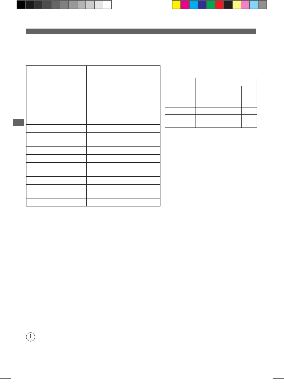
Mit seiner Vielseitigkeit ist die Si-83 ideal für Klimatisierungssysteme (bis zu 20 kW) oder Heizungsinstallationen (bis zu 40 kW)
im Wohnbereich geeignet.
Leistungsdaten:
Stromversorgung:
Kontakt für die Sicherheitsfunktion SI83CE01UN23, SI83CE02UN23,
DE
Maximale Förderhöhe: 5,4 m
Geräuschniveau auf 1m ≤ 45 dBA (gemessen im Schalllabor
Betriebsart 7%: 16s ON - 212s OFF
Schaltpunkte (mm): Fig.3
Zulässige Kondensattemperatur: 55°C (80°C - 1min)
Wannenkapazität: 2,0 l
Überhitzungsschutz 120°C °C (automatisches Wiedereinschal-
Schutzart: IP 44
230V~ 50Hz - 115 W - 1.4 A
SI83CE04UN23, SI83CE05UN23,
SI83CE07UN23: NC: Öffner 5 A ohmsche
Last - 250V
SI83CE41UN23, SI83CE42UN23,
SI83CE43UN23: NO : Schließer 5 A ohmsche
Last - 250V
SI83CE71UN23, SI83CE74UN23: NC/NO:
Schließer 5 A ohmsche Last - 250V
Sauermann, Pumpe in Betrieb mit Wasser)
pH-Wert: > 2.5
ten)
Kondensat-Zuuss (l/h)
Förderhöhe Gesamtlänge der Leitung
5 m 10 m 20 m 30 m
1 m 26 23 17 13
2 m 22 19 14 13
3 m 19 16 11 8
4 m 13 10 7 6
5 m 8 6 4 -
Die in dieser Tabelle angegebenen Druckverluste basieren
auf Berechnungen mit 10 mm Schlauchinnendurchmesser
SICHERHEITSHINWEISE
- Diese Pumpe ist nur für die Förderung von Wasser bestimmt.
- Die Pumpe ist für den Betrieb in Innenräumen konzipiert. Die Pumpe darf nicht als Tauchpumpe eingesetzt und/oder in feuchter
Umgebung aufgestellt werden und ist vor Frost zu schützen.
- Dieses Gerät darf nicht von Personen (einschließlich Kindern) mit eingeschränkten körperlichen, sensorischen oder geistigen
Fähigkeiten bzw. ohne ausreichende Erfahrung und Sachkenntnis benutzt werden, es sei denn, sie werden von einer für ihre
Sicherheit verantwortlichen Person beaufsichtigt oder wurden von dieser mit dem Gebrauch des Gerätes vertraut gemacht.
- Kinder sollten beaufsichtigt werden, damit sie nicht mit dem Gerät spielen.
- Betriebsstörungen und insbesondere eine Beschädigung des Stromkabels müssen von der Sauermann-Kundendienstabteilung
oder gleichwertig qualizierten Fachkräften behoben werden, um jegliche Gefahr auszuschließen.
- Bei Modellen, die nicht über eine Steckdose angeschlossen sind, muss gemäß den Installationsvorschriften an den festverlegten
Leitungen eine Möglichkeit vorgesehen werden, das Gerät vom Stromnetz zu trennen.
- Die Pumpe darf nicht in Bereichen montiert werden, in denen Luft aufbereitet wird (z. B. Plenum oder Luftaufbereitung in einer
Kondensatoreinheit).
WARNHINWEIS: Stromschlaggefahr: Diese Pumpe verfügt über ein Erdungskabel. Überprüfen Sie den ordnungsgemäßen
Anschluss des Kabels an die Erdung, um die Gefahr eines Stromschlags gering zu halten.
1/ INBETRIEBNAHME
a/ Netzanschluss
Schließen Sie das Stromkabel an das Netz an. Beachten Sie die örtlichen Installationsvorschriften.
Anschluß eines Schutzleiters.
16
Page 17

DE
b/ Elektrischer Alarmanschluss. (Fig. 9)
ACHTUNG (EU): Bei dem Sicherheitskontakt handelt es sich um einen potentialfreien Kontakt NC (Öffner) 250 V max. belastbar
mit 2 A induktive und 5 A Ohmsche Last.
ACHTUNG (USA): Bei dem Sicherheitskontakt handelt es sich um einen potentialfreien Kontakt NC für Anschluß an Schaltkreis
Klasse 2 bis max. 42 V.
Mit diesem Kontakt wird das System bei zu hohem Wasserstand im Pumpenbehälter abgeschaltet, um einen Kondensatüberlauf
zu verhindern.
c/ Hydraulischer Anschluss (Fig. 6-7-8)
Die Pumpe ist waagerecht zu montieren. Das Kondensat kann über die 4 O 30 mm Öffnungen im Deckel auf einer Seite (siehe Abb. 6).
Die Förderung des Kondensats erfolgt über ein Rückschlagventil, an das ein Schlauch (Ø 10mm) mit höchstzulässigem Krümmungsradius von 60 mm anzuschliessen ist. Verwenden Sie für 6-mm-Schläuche das Reduzierstück SINJ18005. In diesem Fall verringert sich
die Fördermenge. Vor dem Anschließen oder Abziehen des Schlauchs nach Möglichkeit das Rückschlagventil ausbauen.
d/ Aufstellung/Montage(Fig. 5-8)
Die Pumpe kann an der Wand und mithilfe von 2 Halterungen an der Decke (für die Deckenmontage müssen die 2 Gewindebolzen
+ Muttern) befestigt bzw. am Boden aufgestellt werden. Die Wasserauslassseite für die Wanne kann frei gewählt werden (linksoder rechtsseitige Montage des Pumpenblocks) Rund um die Pumpe muss ausreichender Freiraum zur Kühlung vorgesehen werden. Achten Sie darauf, dass die Kondensatschläuche nicht abgeklemmt werden. Verwenden Sie bei Bedarf ein Panzerrohr. Siehe
das Kurvendiagramm bezüglich der Verringerung der Fördermenge aufgrund der Druckabnahme.
Brennwerttechnik (EN12056.1, §4.5, §5.8) : Schlauch muss säureresistent sein (ph< 6.5). Die Einleitung ins Kanalsystem sollte
vorzugsweise im Gebäudeinnern erfolgen.
2/ BETRIEB
a/ Funktionsprüfung
Füllen Sie Wasser in die Pumpe. Überprüfen Sie, ob sich die Pumpe ein- und bei gesunkenem Wasserstand wieder ausschaltet. Zur
Überprüfung der Alarmfunktion füllen Sie so lange Wasser in die Pumpe, bis der Alarm ausgelöst wird (Abschaltung des Geräts,
akustischer und optischer Alarm usw.).
b/ Reinigung
ACHTUNG: Vor jeder Reinigung muss das Gerät ausgeschaltet werden.
Das Pumpeninnere muss regelmäßig gereinigt werden. Nehmen Sie die Wanne der Pumpe ab und reinigen Sie sie mit einer 5%
igen Bleich/Wasserlösung (siehe Abb. 10. Der Motorblock der Pumpe kann für diese Aktion an der Wand montiert bleiben). Achten
Sie darauf, dass der Schwimmer nicht verunreinigt wird. Setzen Sie die Wanne wieder ein und führen Sie nochmals eine Funktionsprüfung für die Pumpe (§ 2.a) und den Alarm aus.
DE
3/ GEWÄHRLEISTUNG
24 Monate : https://sauermanngroup.de/de/garantie
17
Page 18
NL
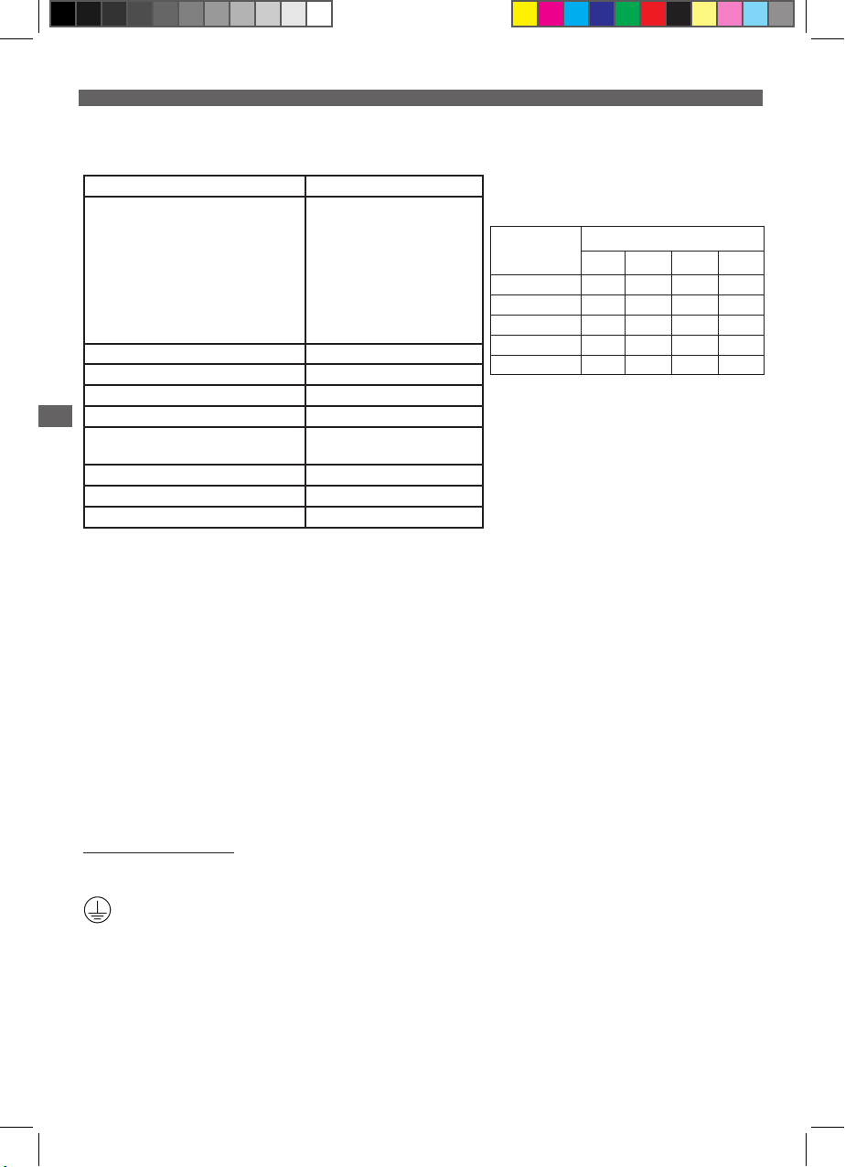
De Si-83 centrifugaalpomp uit : airco’s tot 20 kW / gasketels tot 40 kW
Technische gegevens:
Stroomvoorziening
Alarmcontact SI83CE01UN23, SI83CE02UN23,
Maximaal niveau opvoerhoogte 5,4m
Werking 7%: 16s ON - 212s OFF
Detectieniveau (mm) Fig.3
NL
Geluidsniveau op 1m ≤ 45 dBA
Maximum temperatuur van de condens en
zuurtegraad
Volume van de bak 2.0 l
Thermische beveiliging (oververhitting) 120°C (automatische herstart)
Beveiliging IP 44
230V~ 50Hz - 115 W - 1.4 A
SI83CE04UN23, SI83CE05UN23,
SI83CE07UN23 : NC: max. 5 Amp
- 250V
SI83CE41UN23, SI83CE42UN23,
SI83CE43UN23: NO: max. 5 Amp
- 250V
SI83CE71UN23, SI83CE74UN23 :
NC/NO: max. 5 Amp - 250V
55°C (80°C - 1min), pH>2.5
Inkomende hoeveelheid (l/h)
Förderhöhe Gesamtlänge der leitung
5 m 10 m 20 m 30 m
1 m 26 23 17 13
2 m 22 19 14 13
3 m 19 16 11 8
4 m 13 10 7 6
5 m 8 6 4 -
De weerstanverliezen vastgesteld in deze tabel zijn berekend met slangen met een diameter van 10 mm
WAARSCHUWINGEN
- Deze pomp is uitsluitend bedoeld voor een gebruik met water.
- De pomp is uitsluitend bedoeld voor een gebruik binnenshuis. De pomp mag niet ondergedompeld worden en / of op een
vochtige plek geplaatst worden en dient vorstvrij gehouden te worden.
- Dit apparaat is niet bestemd voor een gebruik door personen (inclusief kinderen) waarvan de lichamelijke, zintuiglijke of geestelijke vermogens verminderd zijn of door personen zonder enige ervaring of kennis, tenzij zij via een voor hun veiligheid verantwoordelijke persoon onder toezicht staan of van tevoren instructies hebben ontvangen betreffende het gebruik van het apparaat.
- Er moet toezicht op kinderen zijn, zodat zij niet met het apparaat kunnen spelen.
- In geval van een defect en met name wanneer het netsnoer beschadigd is, moeten de reparatiewerkzaamheden uitgevoerd
worden door de servicedienst van Sauermann of door personen met dezelfde vakbekwaamheid, teneinde gevaarlijke situaties te
voorkomen.
- Voor de modellen zonder elektriciteitsaansluiting moet een uitschakelmogelijkheid voorzien worden op de vaste elektriciteitsleidingen overeenkomstig de installatievoorschriften.
WAARSCHUWING: Elektrocutiegevaar. Deze pomp is voorzien van een geaard netsnoer. Om het risico van elektrocutie
te verminderen, moet u controleren of de pomp op de juiste wijze geaard is.
1/ INGEBRUIKNAME
a/ Aansluiting op het lichtnet
Sluit het netsnoer aan op een spanningsnet. Neem de plaatselijk geldende installatievoorschriften in acht.
Identiceer een beschermende aardklem.
b/ Elektrische aansluiting van het alarm
BELANGRIJK: voor de elektrische aansluiting van het alarm beschikt u over een droog contact met een vermogen van 250 V en
een uitschakelvermogen van 2 A inductief en 5 A met weerstand. Wij raden u aan dit contact te gebruiken om de koelproductie
te onderbreken indien er gevaar voor overlopen bestaat (zie g. 9). Zie voor het wijzigen van dit type contact (g.9).
18
Page 19

NL
c/ Hydraulische aansluiting (Fig 6-7-8)
De pomp wordt horizontaal onder het apparaat geplaatst en vangt de condens op, ofwel via de bovenzijde met behulp van
4 openingen van Ø 30 mm de ene zijde (zie g 6). Het opvoeren geschiedt via de terugslagklep waarop een slang met een binnendiameter van 10 mm wordt bevestigd, waarvan de maximaal toelaatbare krommingsstraal 60 mm is. Gebruik voor slangen van Ø
6 mm het verloopstuk Ø 6 x Ø 10 mm. In dit geval wordt de hoeveelheid verminderd. Voor het monteren of demonteren van de
slang van de klep verdient het de voorkeur deze van tevoren te verwijderen.
d/ Installatie / instelling (Fig 5-8)
De pomp kan tegen een muur bevestigd worden, op de vloer geplaatst worden of aan het plafond opgehangen worden met
behulp van twee bevestigingslipjes (voor montage aan het plafond moeten twee stangetjes met schroefdraad + moeren). Het
is tevens mogelijk de wateruitlaat aan de hand van de bak te kiezen. Omkeerbaar pompblok. Rond de pomp moet er ruimte vrij
blijven om het afkoelen te vergemakkelijken. Zorg dat de condensslangen niet samengeknepen worden. Gebruik, indien nodig, een
gewapende slang. Bekijk voor het verminderen van de hoeveelheid als gevolg van drukval de kromme.
Verwarming (EN12056.1, §4.5, §5.8) : de buis van Ø20 mm moet tegen zuur water bestendig zijn (pH<6.5). Opvoering binnen
aangeraden.
2/GEBRUIK
a/ Werking
Doe water in de pomp. Controleer of de pomp inschakelt en uitschakelt wanneer het waterpeil gezakt is. Giet voor het controleren
van de werking van het alarm voortdurend water in de pomp, totdat de alarmfunctie ingeschakeld wordt (uitschakeling apparaat,
gelui- of lichtalarm, enz.).
b/ Reiniging
LET OP: voor alle werkzaamheden aan de pomp moet deze spanningloos gemaakt worden.
De binnenzijde van de pomp moet regelmatig gereinigd worden. Verwijder de bak van de pomp en reinig deze met een oplossing
met 5 % bleekwater (zie g. 10, de kap kan tijdens deze operatie op de muur bevestigd blijven). Zorg ervoor dat de vlotter schoon
blijft. Zet de bak terug en test opnieuw de werking van de pomp (§ 2.a) en het alarm.
3/ GARANTIE.
24 Monate : https://sauermanngroup.com/en/warranty
NL
19
Page 20
RU
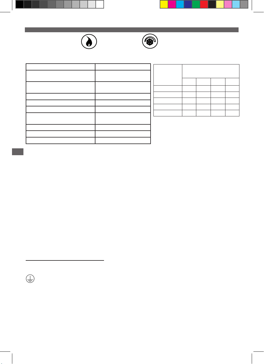
< 40 kW < 20 kW
Технические характеристики:
Электропитание
Аварийный переключатель:
размыкатель
Максимальная высота отведения
конденсата
Уровень шума (1 m) ≤ 45 dBA
Рабочий режим насоса 7%: 16s ON - 212s OFF
Уровни обнаружения (мм) Fig.3
Максимальная температура и
кислотность конденсата
Объем бака 2.0 l
Тепловая защита (перегрев) 120 °C (с перезагрузкой)
Степень защиты IP 44
ПРЕДУПРЕЖДЕНИЯ
RU
- Этот насос предназначен для использования только с водой.
230V~ 50Hz - 115 W - 1.4 A
5A резистивной нагрузки
– 250 В
5,4m
55°C (80°C- 1min), pH>2.5
Фактическая пропускная способность
Высота
Общая длина трубы
нагнетания
5 m 10 m 20 m 30 m
1 m 26 23 17 13
2 m 22 19 14 13
3 m 19 16 11 8
4 m 13 10 7 6
5 m 8 6 4 -
Потери напора, определенные в этой
таблице, рассчитаны с помощью системы
гибких труб с внутр. диаметром 10 мм.
- Этот насос предназначен для использования только в помещениях. Не погружайте и/или не
помещайте насос во влажную среду и защищайте от замерзания.
- Устройство не предназначено для использования лицами (в том числе детьми) с ограниченными
физическими, сенсорными или умственными способностями или лицами, не обладающими
соответствующим опытом и знаниями, кроме случаев, когда со стороны ответственного за их
безопасность лица обеспечивается надлежащий контроль или предварительный инструктаж
относительно использования устройства.
- Дети должны использовать устройство под присмотром взрослых. Не допускайте, чтобы дети
играли с устройством.
- В случае неисправности и, в частности, повреждения кабеля питания любые операции по
техобслуживанию должны выполняться службой послепродажного обслуживания Sauermann или
лицами с аналогичной квалификацией, чтобы избежать возможных рисков.
- Для моделей без электрической розетки необходимо предусмотреть возможность отключения от
стационарной электрической сети в соответствии с правилами установки.
ПРЕДУПРЕЖДЕНИЕ: опасность поражения электрическим током. Насос оснащен
заземляющим кабелем. Чтобы снизить риск поражения электрическим током, убедитесь, что он
соответствующим образом соединен с устройством заземления.
1/ ВВОД В ЭКСПЛУАТАЦИЮ
a/ Подключение к сети (рис. 9)
Подключите кабель питания к сети. Соблюдайте местные правила по установке.
Определяет защитную клемму заземления.
b/ Электрическое соединение предохранительного контакта (pис. 9)
ВАЖНО. Для электрического подключения системы сигнализации предусмотрен
беспотенциальный размыкающий контакт с напряжением до 250 В и разрывной способностью 2 A
при индуктивной нагрузке и 5 А при резистивной нагрузке.
Рекомендуется использовать этот контакт для прекращения производства холода в случае
опасности переполнения (рис. 9). Сведения о модификации предохранительного контакта см. на
рис. 9.
20
Page 21

RU
c/ Гидравлическое соединение (рис. 6-7-8)
Насос помещается в горизонтальном положении под устройство, и конденсат поступает в него
либо через верхнюю часть благодаря 4 отверстиям диаметром 30 мм (1 3/16’’), либо с одной или
другой стороны (см. рис. 6).
Нагнетание осуществляется через обратный клапан, на котором будет установлена труба с внутр.
диаметром 10 мм (3/8’’), макс. допустимый радиус изгиба которой составляет 60 мм (2 3/8’’).
Для труб с внутр. диаметром 6 мм (1/4’’) используйте адаптер диаметром 6 x 10 мм (1/4’’ x 3/8’’).
В этом случае пропускная способность будет ограничена. Чтобы установить или снять трубу,
рекомендуется сначала извлечь клапан.
d/ Установка/наладка (рис. 5-8)
Насос может крепиться к стене, на полу или на потолке благодаря двум скобам для крепления (для
потолочного монтажа необходимо использовать два стержня с резьбой + гайки).
С целью обеспечения охлаждения насоса оставьте вокруг него свободное пространство.
Конструкция насоса позволяет отводить конденсат с левой или правой стороны бака. Для этого
нужно поставить насосный блок в нужное положение в бак.
Будьте внимательны, чтобы не защемить трубы с конденсатом.
В случае необходимости используйте армированную трубу.
В случае вопросов относительно снижения пропускной способности в связи с потерей напора
обратитесь к таблице фактических значений пропускной способности.
При использовании в отоплении (EN12056.1, § 4.5, § 5.8) убедитесь, что отводящий конденсат
трубопровод устойчив к воздействию кислых стоков (pH < 6,5). Осуществляйте нагнетание
предпочтительно в помещениях во избежание опасности замерзания трубопровода.
2/ ЭКСПЛУАТАЦИЯ
a/ Проверка работоспособности насоса
Налейте воду в насос. Убедитесь, что насос включается и прекращает работу, когда уровень
воды снова снижается. Чтобы проверить исправность предохранительного контакта, непрерывно
наливайте воду в насос, пока предохранительный контакт не сработает (остановка устройства,
звуковой или визуальный сигнал и т. д.).
NL
RU
b/ Очистка
ВНИМАНИЕ! При выполнении любых операций по техобслуживанию насос должен быть отключен.
Внутреннюю часть насоса необходимо регулярно чистить.
Снимите бак насоса и очистите его с помощью 5%-го раствора жавелевой воды (см. рис. 10;
крышка может оставаться прикрепленной к стенке).
Следите за тем, чтобы поплавок оставался чистым.
Установите бак на место и испытайте работу насоса (§ 2.a) и предохранительного контакта.
3/ ГАРАНТИЯ
24 месяца с даты поставки. :https://sauermanngroup.com/en/warranty
21
Page 22
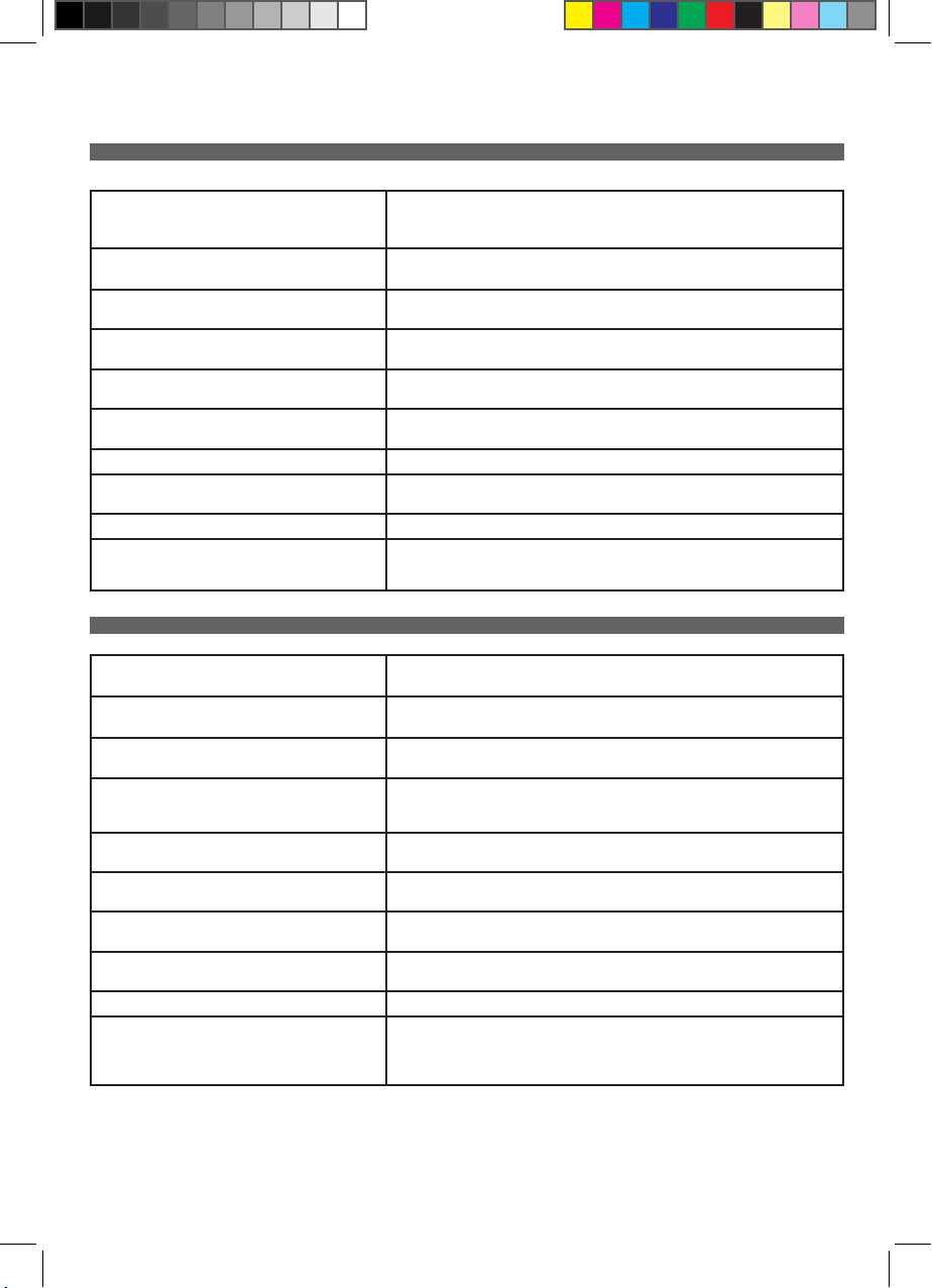
FAQ / TROUBLESHOOTING EN
The pump stops and then restarts after a while.
The pump no longer works (or has a degraded
appearance).
The pump does not start, or works without evacuate
the condensates.
The pump does not start, or works without evacuate
the condensates.
The pump is operating continuously. Check that the removal tubes are not blocked, pinched or frozen. Check that the non-return valve
The condensate goes back down into the tank and the
pump runs with short cycles.
The tank overows. Check that the alarm is correctly connected. Connect the alarm.
The tank overows. Check the compatibility on the inow compared to the data sheet of the pump. Limit the inow or
The alarm does not work. Check that the alarm is correctly connected.
The alarm does not work. Check that the oat is not blocked. Check the presence of biolm. Clean up the pump to remove the
The thermal protection has been triggered. Check the ambient temperature.
If the temperature is too high, please ventilate the area or move the pump if possible in a temperate
environment.
Check the acidity of the condensate. If the condensate has a Ph lower than 2.5, use a Ph neutraliser.
Check that the oat is not blocked. If it is blocked, unblock it.
Check the presence of biolm. If there is biolm, clean up the pump to remove the biolm. Using a
Gel-clear SPSI93T1 tablet can help you to prevent the biolm formation.
is not fouled.
Check the tightness of the check valve. Replace the check valve if necessary.
lower the condensate lifting height.
biolm. Using a Gel-clear SPSI93T1 tablet can help you to prevent the biolm formation.
FAQ / DEPANNAGE FR
La pompe s'arrête puis redémarre après un certain
temps.
La pompe ne fonctionne plus (ou a un aspect dégradé). Vérier l’acidité du condensat. Si le condensat a un Ph inférieur à 2,5, utilisez un neutraliseur de Ph.
La pompe ne démarre pas, ou fonctionne sans évacuer
de condensat.
La pompe ne démarre pas, ou fonctionne sans évacuer
de condensat.
La pompe fonctionne en continu. Vériez que les tubes de refoulement ne sont pas bloqués, pincés ou gelés. Vérier que le clapet
Le condensat redescend dans le bac et la pompe
fonctionne avec des cycles courts.
Le bac déborde. Vérier que l’alarme est correctement branchée.
Le bac déborde. Vérier la comptabilité du débit entrant par rapport à la che technique de la pompe.
L’alarme ne fonctionne pas. Vérier que l’alarme est correctement branchée.
L'alarme ne fonctionne pas. Vérier si le otteur est bloqué.
La protection thermique du moteur est déclenchée. Vérier la température ambiante. Si la température
est trop élevée, veuillez aérer le local ou déplacer si possible la pompe dans un environnement tempéré.
Vérier que le otteur n’est pas bloqué. S’il est bloqué, le débloquer.
Vérier la présence de biolm.
En présence de biolm, nettoyer la pompe pour éliminer le biolm.
L’utilisation d’une pastille Gel-clear SPSI93T1, peut vous aider prévenir la formation de biolm.
anti-retour n’est pas encrassé.
Vérier la bonne étanchéité du clapet anti-retour.
Remplacer le clapet anti-retour si besoin.
Brancher l’alarme.
Limiter le débit d’entrée ou diminuer la hauteur de relevage du condensat.
Vérier la présence de biolm.
Nettoyer la pompe pour éliminer le biolm.
L’utilisation d’une pastille Gel-clear réf SPSI93T1, peut vous aider à prévenir la formation de biolm.
22
Page 23
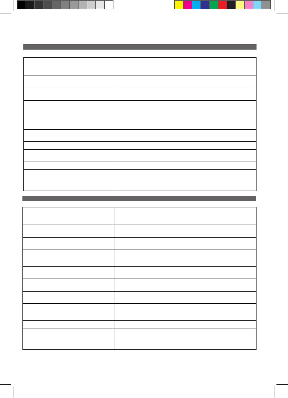
FAQ / RISOLUZIONE DEI PROBLEMI IT
La pompa si arresta poi riparte dopo un po’ di tempo.
La pompa non funziona più (o sembra rovinata). Vericare l’acidità della condensa. Se la condensa ha un Ph inferiore a 2,5, utilizzare un neutraliz-
La pompa non si avvia o funziona senza evacuazione
della condensa.
La pompa non si avvia o funziona senza evacuazione
della condensa.
Se la pompa funziona a ciclo continuo. Vericare che i tubi di scarico non siano ostruiti, piegati o congelati. Vericare che la valvola di non
La condensa ricade nella vaschetta e la pompa
funziona a cicli brevi.
Il contenuto fuoriesce dalla vaschetta. Vericare che l’allarme sia collegato correttamente. Collegare l’allarme.
Il contenuto fuoriesce dalla vaschetta. Vericare il calcolo della portata in ingresso rispetto a quanto indicato nella scheda tecnica della
L’allarme non funziona. Vericare che l’allarme sia collegato correttamente.
L’allarme non funziona. Vericare che il galleggiante non sia bloccato.
È scattata la protezione termica del motore. Vericare la temperatura ambiente.
Se la temperatura è troppo alta. Aerare il locale o, se possibile, spostare la pompa in un ambiente
temperato.
zatore di pH.
Vericare che il galleggiante non sia bloccato. Se bloccato, provvedere a sbloccarlo.
Vericare l’eventuale presenza di biolm.
In presenza del biolm, pulire la pompa per eliminarlo.
L’utilizzo di una pastiglia Gel-clear SPSI93T1 può contribuire a prevenire la formazione di biolm.
ritorno non sia incrostata.
ÜVericare la corretta tenuta della valvola di non ritorno.
Sostituire la valvola di non ritorno, se necessario.
pompa. Limitare la portata in ingresso o ridurre l’altezza di scarico della condensa.
Vericare l’eventuale presenza di biolm.
Pulire la pompa per eliminarlo.
L’utilizzo di una pastiglia Gel-clear può contribuire a prevenire la formazione di biolm.
FAQ / RESOLUCIÓN DE AVERÍAS ES
La bomba se detiene y vuelve a ponerse en marcha al
cabo de un tiempo.
La bomba no funciona (o presenta un aspecto
deteriorado).
La bomba no se pone en marcha o funciona sin
evacuar condensado.
La bomba no se pone en marcha o funciona sin
evacuar condensado.
Si su bomba funciona de forma continua. Compruebe que los tubos de absorción no estén obturados, pinzados ni helados. Compruebe que la
El condensado retorna a la bandeja y la bomba funciona en ciclos cortos.
El contenido de la bandeja desborda. Compruebe que la alarma esté correctamente conectada.
El contenido de la bandeja desborda. Compruebe que el caudal entrante corresponda a las especicaciones de la cha técnica de la
La alarma no funciona. Compruebe que la alarma esté correctamente conectada.
La alarma no funciona. Compruebe si el otador está bloqueado.
Está activada la protección térmica del motor. Compruebe la temperatura ambiente.
Si la temperatura es excesiva, ventile el local o, si es posible, desplace la bomba y sitúela en un ambiente
templado.
Compruebe la acidez del condensado.
Si el condensado tiene un pH inferior a 2,5, utilice un neutralizador de pH.
Compruebe que el otador no esté bloqueado.
Si es así, desbloquéelo.
Compruebe la presencia de biolm.
En presencia de biolm, limpie la bomba para eliminarlo.
Puede resultarle útil utilizar una pastilla Gel-clear SPSI93T1 para evitar la formación de biolm.
válvula de retención no esté sucia.
Compruebe la correcta estanqueidad de la válvula antirretorno.
Cambie la válvula antirretorno si es preciso.
Conecte la alarma.
bomba.
Limite el caudal de entrada o reduzca la altura de descarga de condensado.
Compruebe la presencia de biolm.
Limpie la bomba para eliminar el biolm.
Puede resultarle útil utilizar una pastilla Gel-clear para evitar la formación de biolm.
23
Page 24
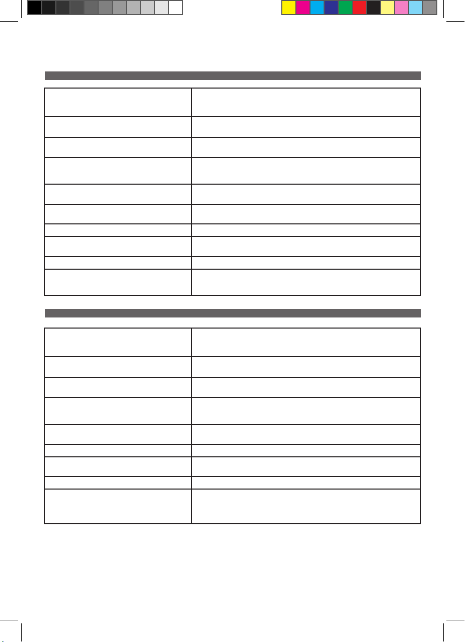
FAQ / STÖRUNGSBEHEBUNG DE
Die Pumpe stoppt und startet nach einiger Zeit wieder.
Die Pumpe funktioniert nicht mehr (oder hat ein
beeinträchtigtes Erscheinungsbild).
Die Pumpe startet nicht oder läuft, ohne das Kondensat abzuleiten.
Die Pumpe startet nicht oder läuft, ohne das Kondensat abzuleiten.
Wenn Ihre Pumpe ohne Unterbrechung arbeitet. Stellen Sie sicher, dass die Kondensatleitungen weder verstopft noch gequetscht oder geklemmt
Das Kondensat ießt wieder in den Tank zurück und
die Pumpe läuft mit kurzen Zyklen.
Der Behälter läuft über. Überprüfen Sie, ob der Alarm korrekt angeschlossen ist. Schließen Sie den Alarm an.
Der Behälter läuft über. Überprüfen Sie, ob die zulaufende Kondensatmenge mit dem zulässigen Wert übereinstimmt.
Der Alarm funktioniert nicht. Überprüfen Sie, ob der Alarm korrekt angeschlossen ist.
Der Alarm funktioniert nicht. Überprüfen Sie, ob der Schwimmer blockiert ist. Überprüfen Sie das Vorliegen von Biolm. Entfernen
Der Überhitzungsschutz wurde ausgelöst. Überprüfen Sie die Umgebungstemperatur.
Wenn die Temperatur zu hoch ist, belüften Sie bitte den Bereich oder positionieren Sie die Pumpe, wenn
möglich, in einer kühleren Umgebung.
Überprüfen Sie den Säuregehalt des Kondensats. Wenn das Kondensat einen PH-Wert von weniger
als 2,5 aufweist, verwenden Sie eine Ph-Neutralisation.
Überprüfen Sie, ob der Schwimmer blockiert ist. Falls ja, lösen Sie die Blockade.
Überprüfen Sie, ob Biolm vorliegt (auch in den Zu- und Ableitungen). Falls ja, entfernen Sie den
Biolm und reinigen die Pumpe. Die Verwendung einer Gel-clear SPSI93T1 Tablette kann Ihnen
helfen, die Bildung von Biolmen zu verhindern.
noch eingefroren sind. Stellen Sie sicher, dass das Rückschlagventil nicht verunreinigt ist.
Überprüfen Sie die Dichtheit des Rückschlagventils. Ersetzen Sie bei Bedarf das Rückschlagventil.
Begrenzen Sie den Zulauf oder reduzieren Sie die Förderhöhe des Kondensats.
Sie gegebenenfalls den Biolm und reinigen die Pumpe. Die Verwendung einer Gel-clear SPSI93T1
Tablette kann Ihnen helfen, die Bildung von Biolmen zu verhindern.
FAQ / REPARATIE NL
De pomp stopt en begint na enige tijd opnieuw te
werken.
De pomp werkt niet meer (of is beschadigd). Verieer de zuurtegraad van de condens.
De pomp start niet of werkt zonder de condens af te
voeren.
De pomp start niet of werkt zonder de condens af te
voeren.
De condens daalt af in de bak en de pomp werkt met
korte cycli.
De bak loopt over. Verieer of het alarm goed is aangesloten. Sluit het alarm aan.
De bak loopt over. Verieer of de inkomende hoeveelheid overeenkomt met de technische gegevens van de pomp.
Het alarm werkt niet. Verieer of het alarm goed is aangesloten.
Het alarm werkt niet. Verieer of de vlotter niet geblokkeerd is.
De thermische beveiliging van de motor is ingeschakeld. Verieer de omgevingstemperatuur. Als de
temperatuur te hoog is. Gelieve de ruimte te luchten of, indien mogelijk, de pomp te verplaatsen naar
een omgeving met een gematigde temperatuur.
Als de pH-waarde van de condens lager is dan 2,5, dient een pH-neutralisator gebruikt te worden.
Verieer of de vlotter niet geblokkeerd is.
Als dat wel het geval is, moet deze gedeblokkeerd worden.
Verieer of er biolm aanwezig is.
Als dat het geval is, moet u de pomp reinigen en de biolm verwijderen.
Het gebruik van een tablet Gel-clear SPSI93T1 kan u helpen de vorming van biolm te voorkomen.
Verieer of de terugslagklep goed afgedicht is.
Vervang, indien nodig, de terugslagklep.
Beperk de inkomende hoeveelheid of verlaag de oppomphoogte van de condens.
Verieer of er biolm aanwezig is.
Reinig de pomp om de biolm te verwijderen.
Het gebruik van een tablet Gel-clear kan u helpen de vorming van biolm te voorkomen.
24
Page 25
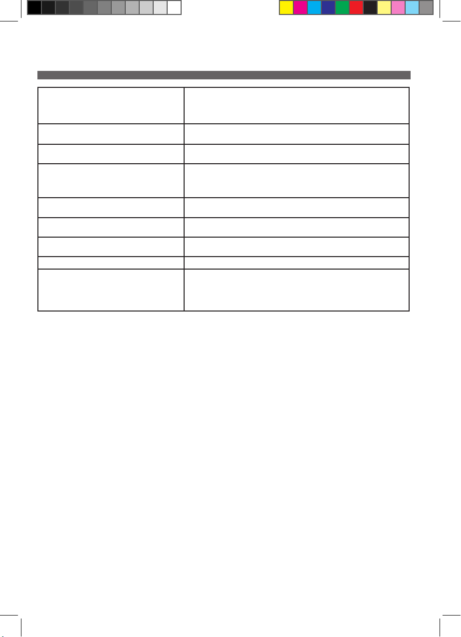
Часто задаваемые вопросы / устранение неисправностей RU
Насос прекращает работу, а через некоторое
время снова запускается.
Насос перестал работать (или кажется
поврежденным).
Насос не запускается или работает, но не
удаляет конденсат.
Насос не запускается или работает, но не
удаляет конденсат.
Конденсат снова оседает в баке, и насос
работает короткими циклами.
Бак переполняется. Проверьте правильность включения сигнала оповещения.
Бак переполняется. Проверьте соответствие входящего потока техническому описанию насоса.
Сигнал оповещения не срабатывает. Проверьте правильность включения сигнала оповещения.
Сигнал оповещения не срабатывает. Проверьте, не обездвижен ли поплавок.
Сработала функция термозащиты двигателя. Проверьте температуру
окружающей среды.
Если температура слишком высокая, проветрите помещение или, если это
возможно, переместите насос в место с умеренной температурой.
Проверьте кислотность конденсата.
Если уровень pH ниже 2,5, воспользуйтесь нейтрализатором pH.
Проверьте, не обездвижен ли поплавок.
Если он обездвижен, освободите его.
Проверьте наличие биопленки.
При наличии биопленки очистите насос, чтобы удалить биопленку.
Для предотвращения образования биопленки может быть эффективным
использование таблетки Gel-clear SPSI93T1.
Проверьте герметичность обратного клапана.
При необходимости замените обратный клапан.
Включите сигнал.
Отрегулируйте входящий поток или уменьшите высоту отвода конденсата.
Проверьте наличие биопленки.
Очистите насос, чтобы удалить биопленку.
Для предотвращения образования биопленки может быть эффективным
использование таблетки Gel-clear.
25
Page 26

Page 27

Page 28

SAUERMANN FRANCE
Parc d’activités de l’Orée de Chevry
Route de Férolles
77173 Chevry Cossigny / France
Tel. : +33 (0)1 60 62 06 06
Fax : +33 (0)1 60 62 09 09
E-mail : [email protected]
www.sauermannpumps.fr
SAUERMANN GmbH
Leibnizstrasse 6
74211 Leingarten / Deutchland
Tel : + 49 (0) 71 31 / 3 99 990
E-mail : [email protected]
www.sauermanngroup.de
Sauermann Hong Kong Ltd.
16/F.,Rykadan Capital Tower
135 hoi Bun Road
Kwun Tong, Kowloon, Hong Kong SAR
Email : [email protected]
www.sauermannpumps.hk
SAUERMANN ITALY
Via G.Golini 61/11
40024 Castel S.Pietro Terme (Bo)
Italia
Tel : (+39)-051-6951033
Fax: (+39)-051-942254
Email: [email protected]
www.sauermannpumps.it
Sauermann Ibérica Pumps &
Instruments, S.L.U.
C/Albert Einstein 33
Planta 3. P. I. Santa Margarida II
08223 Terrassa
España
Tel : (+34)9 37 46 37 55
Email : [email protected]
www.sauermann.es
SAUERMANN N.A.
140 Fell Court, Ste. 302
Hauppauge, NY 11788
Tel : (+1) 631-234-7600
Fax : (+1) 631-234-7605
E-mail : [email protected]
www.sauermann.us
SAUERMANN CHINA
No. 1 Changxu Road,
Juyan New Park - Jiading District,
Shangai 201808/R.P. China
Tel : (+ 86) 21 691 689 61
Fax : (+ 86) 21 691 689 62
Email : [email protected]
www.sauermannpumps.com.cn
SAUERMANN UK
Units 7-9, Trident Business Park
Amy Johnson Way
Blackpool - Lancashire FY4 2RP
U.K.
Tel : +44 (0) 01253 340170
Fax : +44 (0) 01253 340179
Email: [email protected]
www.sauermannpumps.co.uk
SAUERMANN AUSTRALIA
1/36 Campbell Avenue
Cromer, Sydney
NSW 2099
Australia
Tel : +612 (0) 8880 4631
www.sauermannpumps.com.au
sauermanngroup.com
 Loading...