

Page 1
Page 2

Page 3

TABLE OF CONTENTS
1 SAFETY INSTRUCTIONS.................................................................................................................................................4
1.1 Precautions........................................................................................................................................................... 4
1.2 Symbols................................................................................................................................................................4
2 DEVICE COMPONENTS..................................................................................................................................................5
2.1 Use.......................................................................................................................................................................5
2.2 Applications.......................................................................................................................................................... 5
2.3 Selection...............................................................................................................................................................5
2.4 Layout.................................................................................................................................................................. 6
2.5 Buttons.................................................................................................................................................................6
2.6 LEDs.....................................................................................................................................................................6
2.7 Connections..........................................................................................................................................................6
2.8 Mounting.............................................................................................................................................................. 6
3 TECHNICAL FEATURES..................................................................................................................................................7
3.1 Devices................................................................................................................................................................. 7
3.2 Programmed units.................................................................................................................................................9
3.3 Free units.............................................................................................................................................................. 9
3.4 Housing..............................................................................................................................................................10
3.5 Directive: FCC part 15.........................................................................................................................................10
3.6 Optional probes and cables for KT 320 data loggers.............................................................................................11
3.7 Thermocouple probes for KTT 320 data loggers....................................................................................................12
3.8 Connect a probe to the universal input................................................................................................................. 12
3.9 Connect a probe to the thermocouple input.........................................................................................................12
3.10 Dimensions.......................................................................................................................................................13
3.10.1 Devices.....................................................................................................................................................13
3.10.2 Wall mount (option)................................................................................................................................... 13
3.11 Warranty period................................................................................................................................................. 13
4 USE OF THE DEVICE....................................................................................................................................................14
4.1 Display................................................................................................................................................................ 14
4.2 Function of LEDs................................................................................................................................................. 14
4.3 Configuration, data logger download and data processing with the KILOG software..............................................15
4.4 Function of buttons............................................................................................................................................. 15
4.4.1 Groups organization....................................................................................................................................17
4.4.2 Measurements scroll....................................................................................................................................17
4.5 PC communication..............................................................................................................................................18
5 BLUETOOTH® FUNCTION............................................................................................................................................. 19
6 MAINTENANCE........................................................................................................................................................... 19
6.1 Replace the batteries........................................................................................................................................... 19
6.2 Device cleaning................................................................................................................................................... 19
6.3 Safety lock wall mount with padlock....................................................................................................................19
7 CALIBRATION.............................................................................................................................................................20
7.1 KCC 320: perform a CO2 measurement verification...............................................................................................20
7.2 KP 320 – KP 321: perform an auto-zero...............................................................................................................20
8 ACCESSORIES............................................................................................................................................................. 21
9 TROUBLESHOOTING.................................................................................................................................................... 21
Page 4

1 SAFETY INSTRUCTIONS
1.1 Precautions
Please always use the device in accordance with its intended use, and within the parameters described in the technical
features page 7 in order not to compromise the protection ensured by the device.
1.2 Symbols
For your safety and in order to avoid damage to the device, please follow the procedures described in this user
manual and carefully read the notes that are preceded by the following symbol:
The following symbol will also be used in this user manual:
Please carefully read the information notes indicated after this symbol.
4
SAFETY INSTRUCTIONS
Page 5
2 DEVICE COMPONENTS
2.1 Use
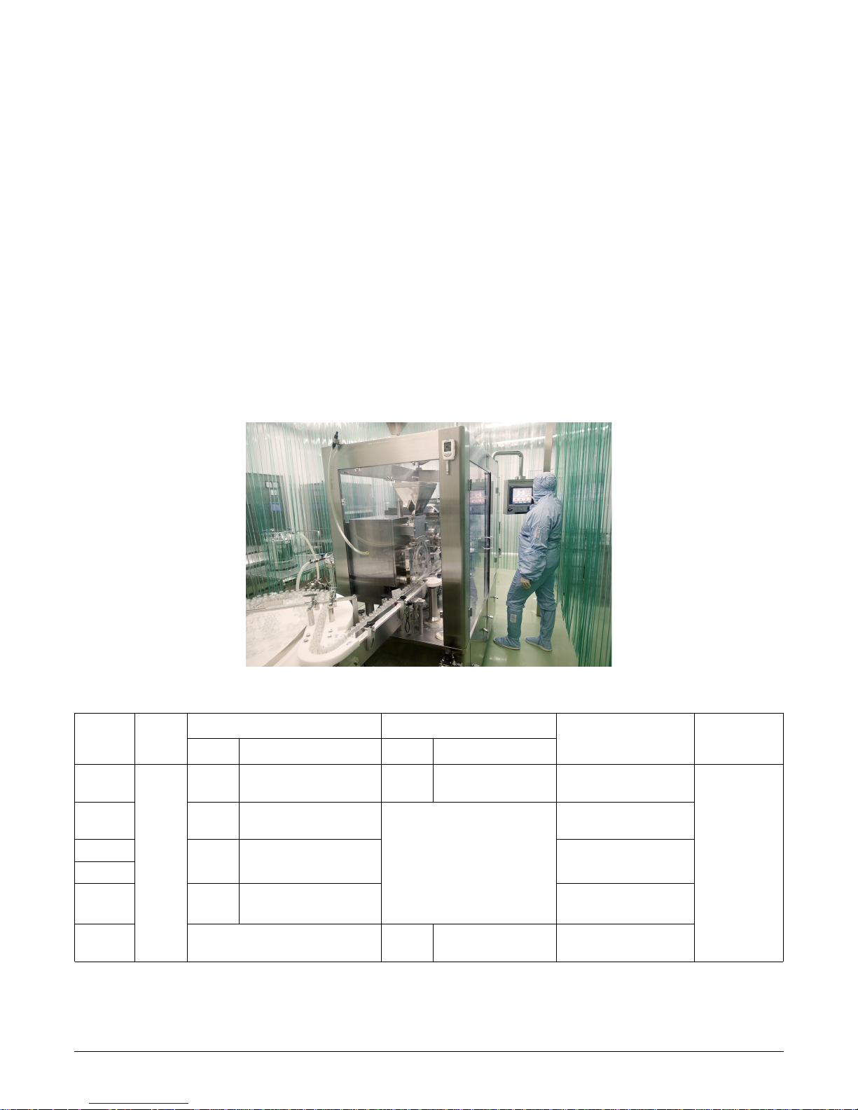
The class 320 Sauermann data loggers measure several parameters:
• KT 320: internal measurement of temperature with two universal inputs for probe
• KCC 320: internal measurement of temperature, humidity, atmospheric pressure and CO
2
• KP 320 – KP 321: internal measurement of differential pressure with two measuring ranges
• KPA 320: internal measurement of temperature, humidity and atmospheric pressure
• KTT 320: model with four thermocouple inputs
Communication between device and PC is carried out with a USB cable with a micro-USB female connector.
The low-energy Bluetooth® communication (option to deactivate this function) for communication with smartphones and
tablets, operating with Android and IOS.
2.2 Applications
The Sauermann data loggers are ideal for multiple surveillance parameters (temperature, humidity, light, current, voltage,
pulse, relative pressure). They ensure traceability in the food industry environment, as well as validate that industrial
installations are functioning properly.
2.3 Selection
Part No. Display
Internal sensors External sensors
Parameters
Number of
recording
points
Number Type Number Type
KT 320
P
1 Temperature 2
Inputs for smart plug*
probes
Temperature, humidity,
current, voltage & pulse
2,000,000
KCC 320 4
Temperature, humidity,
atmospheric pressure & CO
2
N/A
Temperature, humidity,
atmospheric pressure & CO
2
KP 320
1 Differential pressure Differential pressure
KP 321
KPA 320 3
Temperature, humidity &
atmospheric pressure
Temperature, humidity &
atmospheric pressure
KTT 320 N/A 4
Inputs for
thermocouple** probes
Temperature
* Input allows compatibility with multiple probes with automatic recognition and the adjustment parameters storage which make them 100% interchangeable. Reference page 11 for
further information.
** More details about thermocouple probes on page 11.
DEVICE COMPONENTS
5
Page 6
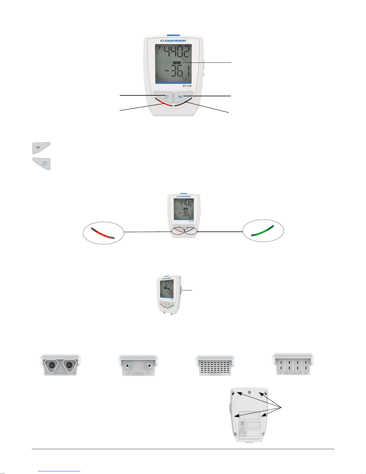
2.4 Layout
2.5 Buttons
OK button: start and stop the dataset, or switch between scrolling group, see page 15.
Selection button: select between values in a scrolling group, see page 15.
2.6 LEDs
2.7 Connections
The communication between the device and the computer is carried out via a USB cable with a female micro-USB
connector.
2.8 Mounting
The class 320 data loggers are equipped with a magnetic case for easy
mounting.
6
DEVICE COMPONENTS
“Selection” button
“OK” button
Micro-USB connector
KT 320: 2 mini-DIN
connections
KCC 320 and
KPA 320
KP 320 and KP 321:
2 pressure connections
KTT 320: 4 mini-thermocouple
connections
Alarm LED
Operating LED
Alarm LED
Operating LED
Magnetic mountings
Display
Page 7

3 TECHNICAL FEATURES
3.1 Devices
KT 320 KTT 320
Parameter
Temperature, humidity, current, voltage, pulse Temperature
Units displayed
1
°F, °C, °Ftd, °Ctd, %RH, mV, V, mA, A
Programmed units: please see the class 320 data
loggers user manual.
Free units: for the free units creation, please see the
KILOG software user manual.
°F, °C
The KTT 320 data loggers require optional thermocouple
probes, reference page 12 for further information.
Resolution
0.1°F, 0.1°C, 0.1%RH, 1 mV, 0.001 V,
0.001 mA, 0.1 A
0.1°F, 0.1°C
External input
Micro-USB female connector Micro-USB female connector
Input for probe
2 smart-plug2 inputs
4 inputs for thermocouple3 probes
(K, J, T, N, S)
Internal sensor
Temperature N/A
Type of sensor
Thermistor (NTC) Thermocouple
Measuring ranges
Internal sensor4:
-40 to 158°F
(-40 to 70°C)
K: -328 to 2372°F (-200 to 1300°C)
J: -148 to 1382°F (-100 to 750°C)
T: -328 to 752°F (-200 to 400°C)
N: -328 to 2372°F (-200 to 1300°C)
S: 32 to 3200°F (0 to 1760°C)
Accuracies
5
±0.8°F from -4 to 158°F
(±0.4°C from -20 to 70°C)
±1.5°F below -4°F
(±0.8°C below -20°C)
K, J, T, N: ±0.8°F from 32 to 2372°F
(±0.4°C from 0 to 1300°C)
±(0.3% of the reading +0.8°F) below 32°F
(±(0.3% of the reading +0.4°C) below 0°C)
S: ±1.1°F (±0.6°C)
Alarm set points
2 alarm set points per channel 2 alarm set points per channel
Frequency of measurement
1 s to 24 h 1 s to 24 h
Operating temperature
-40 to 158°F (-40 to 70°C) -4 to 158°F (-40 to 70°C)
Storage temperature
-40 to 185°F (-40 to 85°C) -40 to 185°F (-40 to 85°C)
Battery life
7 years
6
7 years
6
Warranty
1 year 1 year
Directives
2011/65EU RoHS II; 2012/19/EU WEEE; FCC part 157; UL 61010
1
Some units are available only with optional probes.
2
Input allows compatibility with multiple probes. Reference page 11 for further information.
3
The KTT 320 data loggers require optional thermocouple probes, reference page 12 for further information.
4
Other measuring ranges are available according to the connected probe: see optional probes and cables page 11.
5
All accuracies specified in this document were conducting in laboratory conditions and can be guaranteed for measurement carried out in the same conditions, or carried out with
calibration compensation.
6
On the basis of 1 measurement each 15 minutes at 77°F (25°C).
7
More details about FCC part 15 directive on page 10.
TECHNICAL FEATURES
7
Page 8

KCC 320 KPA 320
Units displayed
°F, °C, %RH, hPa, ppm °F, °C, %RH, hPa
Resolution
0.1 °F, 0.1 °C, 1 ppm, 0.1 %RH, 1 hPa 0.1 °F, 0.1 °C, 0.1%RH, 1 hPa
External input
Micro-USB female connector Micro-USB female connector
Input for probe
N/A N/A
Internal sensor
Humidity, temperature, atmospheric pressure, CO
2
Humidity, temperature, atmospheric pressure
Type of sensor
Capacitive, piezoresistive, NDIR Capacitive, piezoresistive
Measuring ranges
Temp.: -4 to 158°F (-20 to 70°C)
Humidity: 0 to 100 %RH
Atm. pressure: 800 to 1100 hPa
CO2: 0 to 5000 ppm
Temp.: -4 to 158°F (-20 to 70°C)
Humidity: 0 to 100%RH
Atm. pressure: 800 to 1100 hPa
Accuracies
1
Temp.: ±0.8°F from 32 to 122°F
(±0.4°C from 0 to 50°C)
±1.5°F below 32°F or above 122°F
(±0.8°C below 0°C or above 50°C)
Humidity2: ±2%RH
from 5 to 95% @ 59 to 77°F (15 to 25°C)
Atm. pressure: ±3 hPa
CO2: ±50 ppm ±3% of the reading
Temp.: ±0.8°F from 32 to 122°F
(±0.4°C from 0 to 50°C)
±1.5°F below 32°F or above 122°F
(±0.8°C below 0°C or above 50°C)
Humidity2: ±2%RH
from 5 to 95% @ 59 to 77°F (15 to 25°C)
Atm. pressure: ±3 hPa
Alarm set points
2 alarm set points per channel 2 alarm set points per channel
Frequency of measurements
15 s to 24 h 1 s to 24 h
Operating temperature
32 to 122°F (0 to 50°C) 32 to 122°F (0 to 50°C)
Storage temperature
-40 to 185°F (-40 to 85°C) -40 to 185°F (-40 to 85°C)
Battery life
3 years
3
7 years
3
Warranty
1 year 1 year
Directives
2011/65EU RoHS II; 2012/19/EU WEEE; FCC part 154; UL 61010
1
All accuracies specified in this document were conducted in laboratory conditions and can be guaranteed for measurement carried out in the same conditions, or carried out with
calibration compensation.
2
Factory calibration tolerance: ±0.88 %RH. Temperature dependence: ±0.04 x [((T °F - 32) x 5/9) - 20] %HR (if T≤59°C or T≥77°F) / ±0.04 x (T-20) %RH (if T≤15°C or T≥25°C)
3
On the basis of 1 measurement each 15 minutes at 77°F (25°C).
4
More details about FCC part 15 directive on page 10.
8
TECHNICAL FEATURES
Page 9

KP 320 KP 321
Units displayed
Pa Pa
Measuring range
±1000 Pa ±10,000 Pa
Resolution
1 Pa 1 Pa
Accuracies
1
±0.5% of the reading ±3 Pa ±0.5% of the reading ±30 Pa
External input
Micro-USB female connector Micro-USB female connector
Input for probe
2 pressure connections 2 pressure connections
Internal sensor
Differential pressure Differential pressure
Operating temperature
41 to 122°F (5 to 50°C) 41 to 122°F (5 to 50°C)
Storage temperature
-40 to 185°F (-40 to 85°C) -40 to 185°F (-40 to 85°C)
Alarm set points
2 alarm set points per channel 2 alarm set points per channel
Frequency of measurements
1 s to 24 h 1 s to 24 h
Battery life
7 years
2
7 years
2
Warranty
1 year 1 year
Directives
2011/65EU RoHS II; 2012/19/EU WEEE; FCC part 153; UL 61010
1
All accuracies specified in this document were conducted in laboratory conditions and can be guaranteed for measurement carried out in the same conditions, or carried out with
calibration compensation.
2
On the basis of 1 measurement each 15 minutes at 77°F (25°C).
3
More details about FCC part 15 directive below.
3.2 Programmed units
The available programmed units for KT 320 and KTT 320 data loggers are:
• m/s
• fpm
• m³/s
• °F
• °C
• %HR
• K
• PSI
• Pa
• mmH2O
• inWg
• kPa
• mmHg
• mbar
• g/Kg
• bar
• hPa
• daPa
• °C
td
• °F
td
• °C
tw
• °F
tw
• kj/kg
• mA
• A
• mV
• V
• Hz
• tr/min
• rpm
• ppm
3.3 Free units
For the free units creation, please see the KILOG software user manual.
TECHNICAL FEATURES
9
Page 10
3.4 Housing
Dimensions
KT320: 4.5'' x 3.11'' x 1.39'' (113.2 x 79 x 35.4 mm)
KTT 320, KCC 320, KPA 320: 4.34'' x 3.11'' x 1.39'' (110.2 x 79 x 35.4 mm)
KP 320, KP 321: 4.7'' x 3.11'' x 1.39'' (119.7 x 79 x 35.4 mm)
Weight
KT 320, KCC 320, KP 320, KP 321: 7.27 oz (206 g)
KTT 320 and KPA 320: 7.05 oz (200 g)
Display
2-line LCD screen
Screen: 1.94'' x 1.77'' (49.5 x 45 mm)
2 indication LEDS (red and green)
Control
1 OK button
1 Selection button
Material
Compatible with food industry environment
ABS housing
Protection
IP 65: KT 320, KP 320 and KP 321
1
IP 54: KTT 320
2
IP 40: KCC 320 and KPA 320
PC communication
Micro-USB female connector
USB cable
Battery power supply
2 double AA lithium 3.6 V batteries
Environmental conditions of use
Non-corrosive or combustible gases
Hygrometry: in non condensing conditions
Altitude: 6561' (2000 m)
1
With the pressure connectors plugged for KP 320 and KP 321.
2
With all the thermocouple probes connected.
3.5 Directive: FCC part 15
Changes or modifications not expressly approved by Sauermann could void the user’s authority
to operate the equipment.
This equipment has been tested and found to comply with the limits for a Class B digital device, pursuant to part 15 of the
FCC Rules. These limits are designed to provide reasonable protection against harmful interference in a residential
installation. This equipment generates uses and can radiate radio frequency energy and, if not installed and used in
accordance with the instruction, may cause harmful interference to radio communications. However, there is no guarantee
that interference will not occur in a particular installation. If this equipment does cause harmful interference to radio or
television reception which can be determined by turning the equipment off and on, the user is encouraged to try to correct
interference by one or more of the following measures:
• Reorient or relocate the receiving antenna.
• Increase the separation between the equipment and receiver.
• Connect the equipment into an outlet on circuit different from that to which the receiver is connected.
• Consult the dealer or an experienced radio/TV technician for help.
10
TECHNICAL FEATURES
Page 11
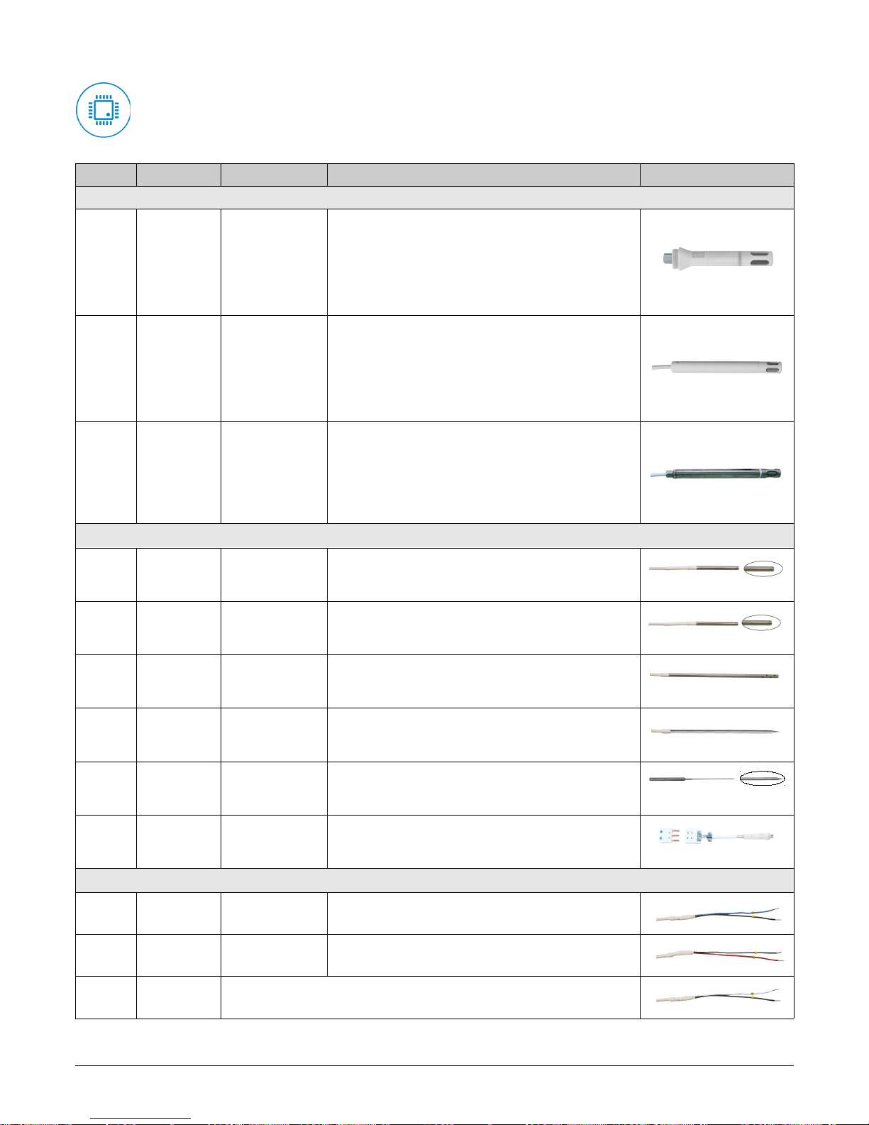
3.6 Optional probes and cables for KT 320 data loggers
All the probes for the KT 320 data loggers have the smart plug technology.
An automatic recognition and the adjustment parameters storage make them 100% interchangeable.
Part No. Description Measuring ranges Accuracies* Image & dimensions
External or ambient thermo-hygrometric probes
KITHA
Interchangeable
hygrometry and
ambient
temperature
probe
0 to 100%RH
-4 to 158°F
(-20 to 70°C)
±2%RH from 5 to 95%RH @ 59°F to 77°F (15 to 25°C)
Temp: ±0.8°F from 32 to 122°F
(±0.4°C from 0 to 50°C)
±1.5°F below 32°F or above 122°F
(±0.8°C below 0°C or above 50°C)
3.7'' (94.5 mm)
KITHP-130
Remote
interchangeable
hygrometry and
temperature
probe
0 to 100%RH
-4 to 158°F
(-20 to 70°C)
±2%RH from 5 to 95%RH @ 59°F to 77°F (15 to 25°C)
Temp: ±0.8°F from 32 to 122°F
(±0.4°C from 0 to 50°C)
±1.5°F below 32°F or above 122°F
(±0.8°C below 0°C or above 50°C)
5.12'' (130 mm)
KITHI-150
Remote
interchangeable
hygrometry and
temperature
probe
0 to 100% RH
-40 to 356°F
(-40 to 180°C)
±1.5%RH from 5 to 95%RH @ 59 to 77°F (15 to 25°C)
±0.6°F from -40 to 32°F
±(0.2% of reading +0.6°F) from 32 to 356°F
(±0.3% of reading ±0.25°C)
5.9'' (150 mm)
General use or insertion Pt100 temperature probes
KIRGA-50
Immersion probe
(IP 65)
-40 to 248°F
(-40 to 120°C)
±0.6°F from -40 to 32°F
±(0.3% of reading +0.5°F) from 32 to 248°F
(±(0.4% of the reading +0.3°C) from -40 to 120°C)
Ø0.24'' x 1.97'' (Ø6 x 50 mm)
KIRGA-150
Immersion probe
(IP 65)
-40 to 248°F
(-40 to 120°C)
±0.6°F from -40 to 32°F
±(0.3% of reading +0.5°F) from 32 to 248°F
(±0.4% of the reading +0.3°C from -40 to 120°C)
Ø0.24 x 5.9'' (Ø6 x 150 mm)
KIRAM-150 Ambient probe
-40 to 248°F
(-40 to 120°C)
±0.6°F from -40 to 32°F
±(0.3% of reading +0.5°F) from 32 to 248°F
(±0.4% of the reading +0.3°C from -40 to 120°C)
Ø0.24 x 5.9'' (Ø6 x 150 mm)
KIRPA-150
Penetration probe
(IP 65)
-58 to 482°F
(-50 to 250°C)
±0.6°F from -58 to 32°F
±(0.3% of reading +0.5°F) from 32 to 482°F
(±0.4% of the reading +0.3°C from -50 to 250°C)
Ø0.24 x 5.9'' (Ø6 x 150 mm)
KIPI3-150-E
Penetration probe
with handle (IP
68)
-58 to 482°F
(-50 to 250°C)
±0.6°F from -58 to 32°F
±(0.3% of reading +0.5°F) from 32 to 482°F
(±0.4% of the reading +0.3°C from -50 to 250°C)
Ø0.12'' x 5.9'' (Ø3 x 150 mm)
KICA-320
Smart adapter for
Pt100 probe
-328 to 1112°F
according to the probe
(-200 to 600°C)
N/A
Ø0.12'' x 5.9'' (Ø3 x 150 mm)
Input current, voltage and impulsion cables
KICT
Voltage input
cable
0 to 5V
or 0 to 10V
±0.2% of the measurement ±1mV
KICC
Current input
cable
0 to 20 mA
or 4 to 20 mA
±0.2% of the measurement ±1µA
KICI Pulse input cable
Maximal voltage: 5V
Type of input: TTL frequency counting
Maximal frequency: 10 KHz
* All accuracies specified in this document were conducted under laboratory conditions and can be guaranteed for measurements carried out in the same conditions, or carried out with compensation.
TECHNICAL FEATURES
11
Page 12
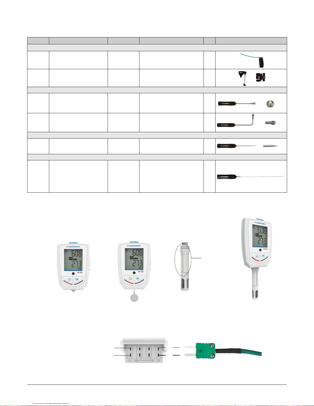
3.7 Thermocouple probes for KTT 320 data loggers
All the thermocouple temperature probes for the KTT 320 data loggers have a class 1 sensitive element as per IEC 584-1, 2
and 3 standards.
Part No. Description Measuring ranges Accuracies* T99** Image & dimensions
Pipes
SKV 150
Contact probe with velcro
Velcro fixing for Ø 3.94'' (Ø 100 mm)
maxi pipes with cable (Tc K)
-4 to 194°F
(-20 to 90°C)
±2.7°F
(±1.5°C)
50 s
SKCT
Contact probe with lamella for Ø 0.34''
to 1.97'' pipes (Ø 10 to 50 mm) with
spring handle and straight cable (Tc K)
-40 to 302°F
(-40 to 150°C)
±2.7°F
(±1.5°C)
15 s
Contact
SCLK 150
Contact probe with lamella with handle
and coiled cable (Tc K)
-40 to 482°F
(-40 to 250°C)
±2.7°F
(±1.5°C)
5 s
5.9'' (150 mm) Ø0.59'' (Ø15 mm)
SCLCK 150
Contact probe with lamella, angled at
90° with handle and coiled cable (Tc K)
-40 to 482°F
(-40 to 250°C)
±2.7°F
(±1.5°C)
5 s
5.9'' (150 mm) Ø0.59'' (Ø15 mm)
Penetration
SPK 150
Penetration probe. Stainless steel contact
tip with pointed contact tip, handle and
coiled cable (Tc K)
-40 to 482°F
(-40 to 250°C)
±2.7°F
(±1.5°C)
30 s
5.9'' (150 mm) Ø0.12'' (Ø3 mm)
Immersion
SIT 300 BT
Very low temperature immersion probe.
Deformable lined contact tip with handle
and coiled cable.
(Tc T)
-328 to 122°F
(-200 to 50°C)
±1.5% of readingfrom -328 to -88.6°F
(±1.5% of reading from -200 to -67°C)
±1.8°F from -88.6 to -40°F
(±1°C from -67 to -40°C)
±0.9°F from -40 to 122°F
(±0.5°C from -40 to 50°C)
2 s
11.81'', Ø0.06'' (300 mm, Ø1.5 mm)
* All accuracies specified in this document were conducted under laboratory conditions and can be guaranteed for measurements carried out in the same conditions, or carried out with compensation.
** Response time. Under application condition.
3.8 Connect a probe to the universal input
➢ Open the mini-DIN connection cap on the bottom of the data logger.
➢ Connect the probe in such a way the mark on the probe is facing the user.
3.9 Connect a probe to the thermocouple input
➢ To connect the thermocouple probe to the bottom of the device, the smallest thermocouple connection must be
placed on top and the largest on the bottom of the plug.
12
TECHNICAL FEATURES
Mark
Small thermocouple connection
Large thermocouple connection
Page 13
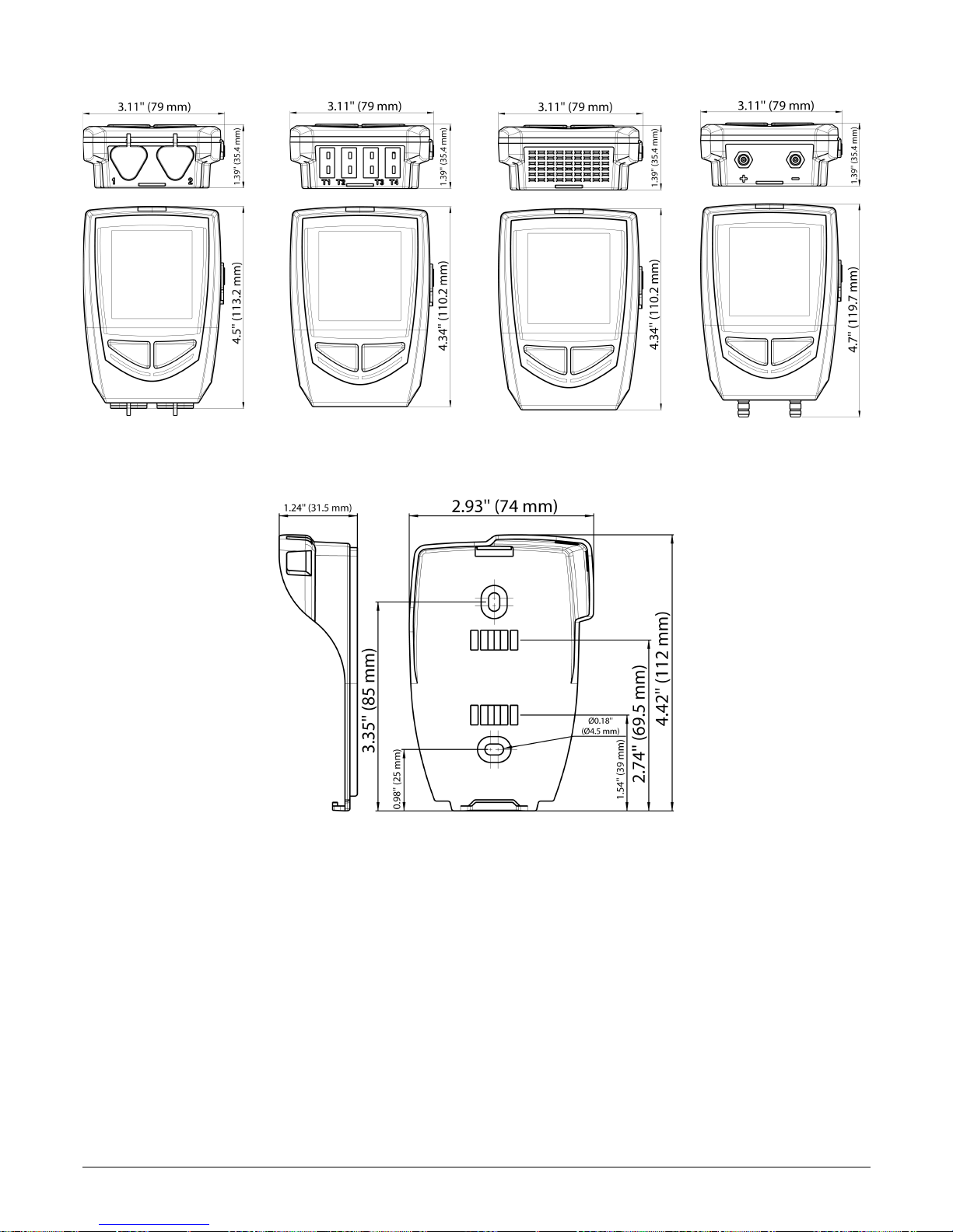
3.10 Dimensions
3.10.1 Devices
3.10.2 Wall mount (option)
3.11 Warranty period
Sauermann data loggers have a 1-year warranty for any manufacturing defect (warranty returns must be processed through
Sauermann's After-Sale Service Department).
TECHNICAL FEATURES
13
KT 320 KCC 320 / KPA 320 KP 320 / KP 321KTT 320
Page 14
4 USE OF THE DEVICE
4.1 Display
The selected values to display during the configuration with the KILOG software will scroll on the
screen every 3 seconds.
The display can be activated or deactivated via the KILOG software.
At extreme temperatures, the display can become difficult to read and the display speed can slow
down at temperatures below 32°F (0°C). This has no effect on the measurement accuracy.
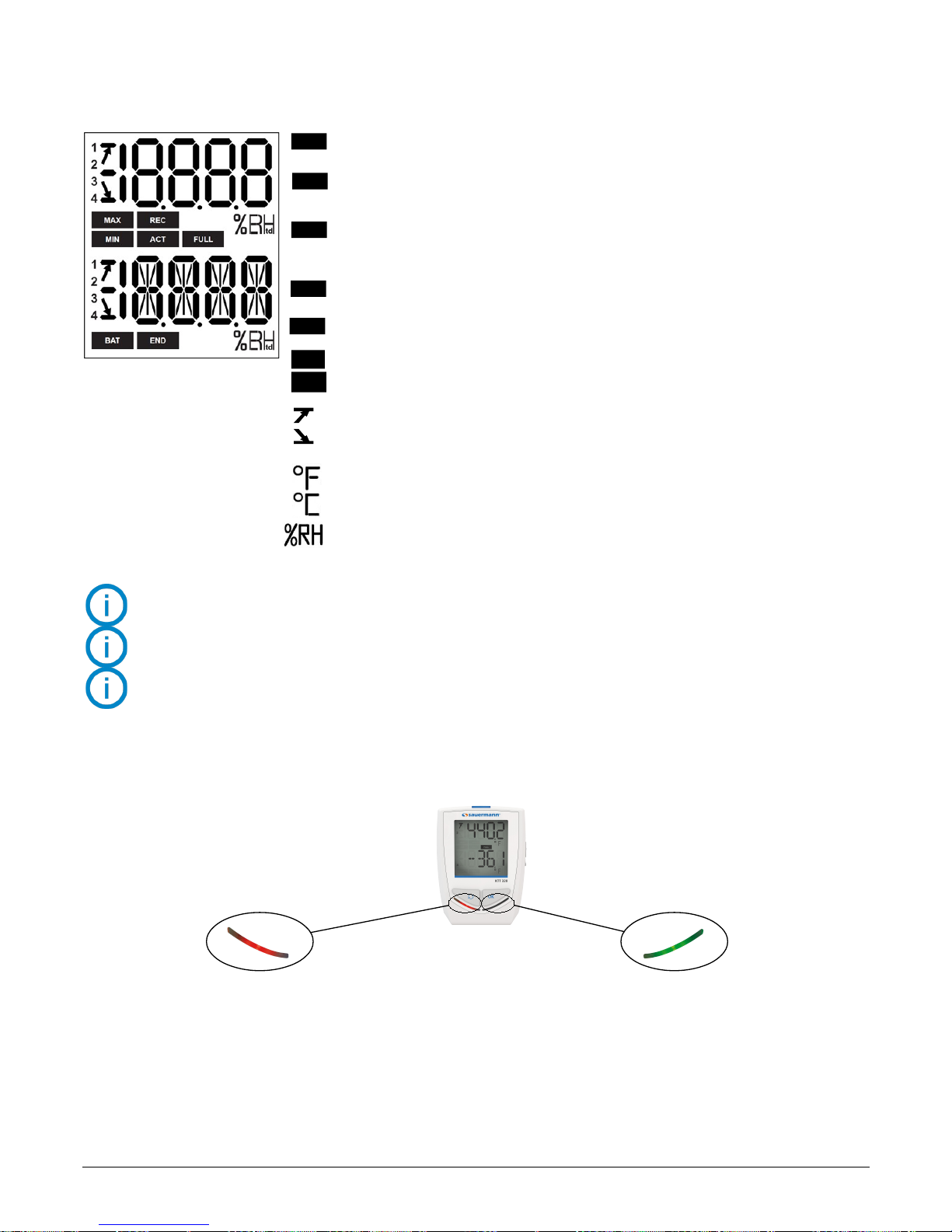
4.2 Function of LEDs
14
USE OF THE DEVICE
Alarm LED
If the red “Alarm” LED has been activated, it has 3 states:
- Always OFF: no setpoint alarms has been exceeded
- Flashing quickly (5 seconds): a threshold is currently
exceeded on at least one channel
- Flashing slowly (15 seconds): at least one threshold has
been exceeded during the dataset
Operating LED
If the green “ON” LED has been activated,
it flashes every 10 seconds during the
recording period.
DATASET is finished.
END
Indicates that one value is being recorded.
Flashing: the DATASET did not start.
REC
Flashing slowly: DATASET is between 80% and 90% of the storage capacity.
Flashing quickly: DATASET is between 90% and 100% of the storage capacity.
Constant: storage capacity full.
FULL
The displayed values are the maximum/minimum values recorded for the channels displayed.
MIN
MAX
Indicates the alarm action type: rising or
falling.
Constant: indicates that the batteries have to be replaced.
BAT
ACT
Screen actualization of measured values.
Indicates the channel number which is
measuring.
Temperature in °Fahrenheit.
Temperature in °Celsius.
1
2
3
4
Relative humidity
Page 15
4.3 Configuration, data logger download and data processing with the KILOG software
Please see the KILOG software user manual: “KILOG-classes-50-120-220-320”.
The date and time updates automatically when a new configuration is loaded.
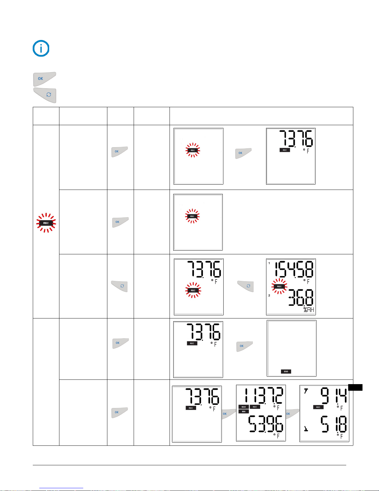
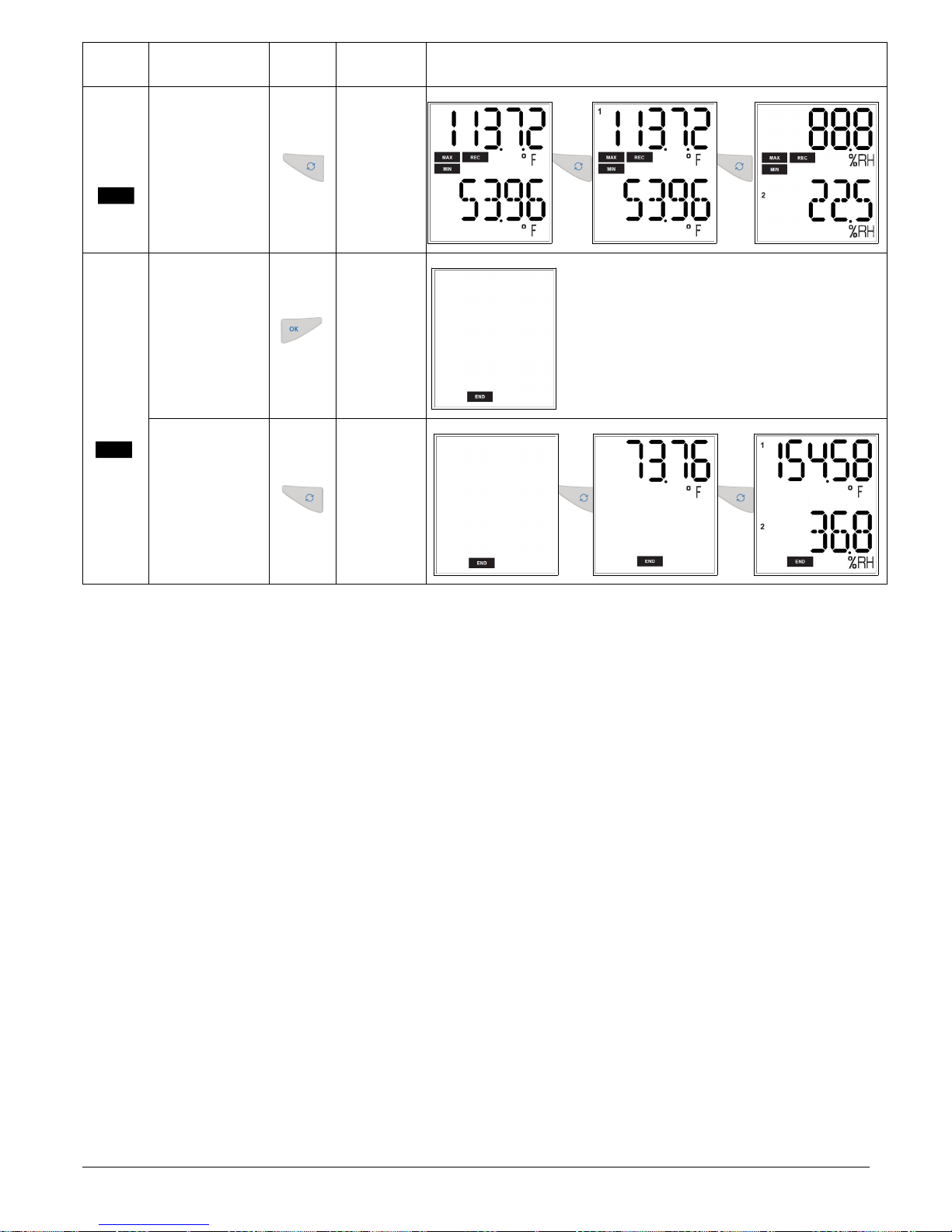
4.4 Function of buttons
OK button: start, stop the dataset or change of scrolling group like described in the following tables.
Selection button: scroll values in the scrolling group like described in the following tables.
Device
state
Type of start/stop
selected
Button
used
Action
generated
Illustration
Waiting
for start
flashes
Start: by button
Stop: Not relevant in
this mode.
Start of dataset
Inactive
Start: by PC,
date/time
Stop: Not relevant in
this mode.
Inactive
Start: not relevant
Stop:
Not relevant in
this mode.
Measurements
scroll
(group 1)*
Dataset in
progress
Start: Not relevant in
this mode.
Stop: by button
Stop of the
dataset
Start: Not relevant
Stop: Not relevant to
change groups
Group change
(groups 2 and
3)*
USE OF THE DEVICE
15
Hold for 5
seconds
Hold for 5
seconds
Hold for 5
seconds
Hold for 5
seconds
* Please see the summary table of the groups organization page 17.
REC
Page 16
Device
state
Type of start/stop
selected
Button
used
Action
generated
Illustration
Group scrolling
(groups 1, 2
and 3)*
Dataset
finished
There is no restart
after the data set
has ended.
Inactive
Measurements
scroll*
* Please see the summary table of the groups organization on page 17.
16
USE OF THE DEVICE
END
REC
Page 17

4.4.1 Groups organization
The table below summarizes the groups organization and measured values available during a measurement dataset.
Group 1 Group 2 Group 3
Measured temperature*
Max. value in temperature
Min. value in temperature
High alarm threshold in temperature
Low alarm threshold in temperature
Measured humidity*
Max. value in humidity*
Min. value in humidity*
High alarm threshold in humidity*
Low alarm threshold in humidity*
Measured CO2*
Max. value in CO2*
Min. value in CO2*
High alarm threshold in CO2*
Low alarm threshold in CO2*
Measured differential pressure*
Max. value in differential pressure*
Min. value in differential pressure*
High alarm threshold in differential pressure*
Low alarm threshold in differential pressure*
Measured atmospheric pressure*
Max. value in atmospheric pressure*
Min. value in atmospheric pressure*
High alarm threshold in atmospheric pressure*
Low alarm threshold in atmospheric pressure*
Parameter 1 of probe 1*
Max. value in Parameter 1 of probe 1*
Min. value in Parameter 1 of probe 1*
High alarm threshold in Parameter 1 of probe 1*
Low alarm threshold in Parameter 1 of probe 1*
Parameter 2 of probe 1*
Max. value in Parameter 2 of probe 1*
Min. value in Parameter 2 of probe 1*
High alarm threshold in Parameter 2 of probe 1*
Low alarm threshold in Parameter 2 of probe 1*
Parameter 1 of probe 2*
Max. value in Parameter 1 of probe 2*
Min. value in Parameter 1 of probe 2*
High alarm threshold in Parameter 1 of probe 2*
Low alarm threshold in Parameter 1 of probe 2*
Parameter 2 of probe 2*
Max. value in Parameter 2 of probe 2*
Min. value in Parameter 2 of probe 2*
High alarm threshold in Parameter 2 of probe 2*
Low alarm threshold in Parameter 2 of probe 2*
Press to switch group.
Press to scroll values in the group.
4.4.2 Measurements scroll
According to the selected parameters during the configuration and according to the type of device, the measurement scroll
is carried out as follows:
Temperature* Humidity* CO2* Differential pressure* Atmospheric pressure* Parameter 1 probe 1*
Parameter 2 probe 1* Parameter 1 probe 2* Parameter 2 probe 2*
* Parameters available according to the device and probe type
USE OF THE DEVICE
17
Page 18
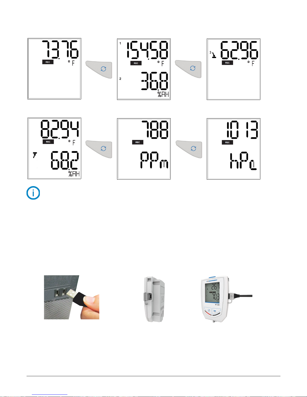
Examples:
• KT 320 data logger with a thermo-hygrometric probe (channel 1) and a temperature probe (channel 2):
• KCC 320 data logger:
The measurements scroll can be carried out by pressing the “Select” button of the data logger or
wait about 3 seconds and the display scrolls automatically.
4.5 PC communication
➢ Insert the CD-ROM in the computer reader and follow the installation procedure of the KILOG software.
More details about the installation procedure in the Kilog user manual.
1. Plug the male USB connector of the cable to the computer USB connection*.
2. Open the USB cap on the right side of the data logger.
3. Connect the male micro-USB connector of the cable to the female micro-USB connector of the device.
18
USE OF THE DEVICE
2
1
3
Or wait 3 seconds Or wait 3 seocnds
Or wait 3 seconds
Or wait 3 seconds
*The computer must be in compliance with the IEC60950 standard.
Page 19
5 BLUETOOTH® FUNCTION
Data loggers of the class 320 have the Bluetooth® function to communicate with a smartphone or a tablet (Androïd or iOS)
via the Mobile application. The data logger is named “Data logger 320” in the list of available devices to the tablet or
smartphone. By default, Bluetooth® is deactivated on class 320 data loggers. Please see the Kilog software applications
user manuals to activate it.
6 MAINTENANCE
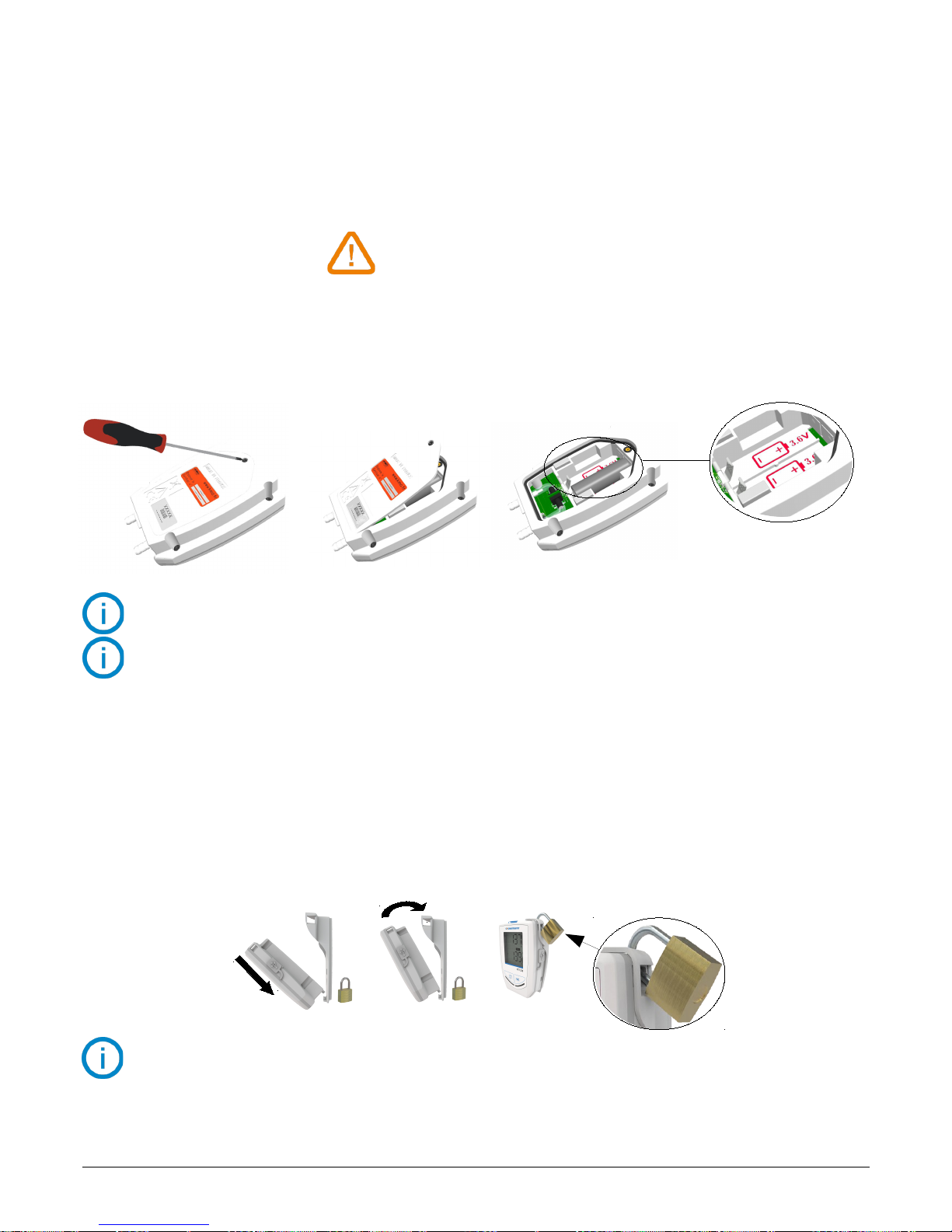
6.1 Replace the batteries
With a 3 to 7 years of battery life*, the data logger guarantees long-term measurement.
To replace batteries:
1. Unscrew the battery hatch on the backside of the data logger with a cross-head screwdriver.
2. The battery hatch opens. Remove the old batteries.
3. Insert the new batteries and check the polarity.
4. Replace the battery hatch and secure the 4 screws with a screwdriver.
Only use trademark or high quality batteries in order to guarantee proper battery life.
After the battery replacement, the device must be reconfigured.
6.2 Device cleaning
Please avoid any aggressive solvent.
Please protect the device and probes from any cleaning product containing formaldehyde, that may be used to clean rooms
and ducts.
6.3 Safety lock wall mount with padlock
➢ Mount the safety lock support on the desired place.
1. Set the data logger on the support starting with the bottom part
2. Clip the data logger on the support by placing the logger into the mount
3. Insert the padlock to ensure the safety lock function
The padlock can be replaced by a safety sealed
The data logger can be placed on the screw-mount without the safety lock function
➢ To remove the data logger from the support, proceed on reverse order.
MAINTENANCE
19
1 2 3
1 2 3
4
* On the basis of 1 measurement each 15 minutes at 77°F (25°C).
Page 20
7 CALIBRATION
Calibration certificates are available (contact the Sauermann office for more information).
We recommend annual calibration.
7.1 KCC 320: perform a CO2 measurement verification
To avoid potential drifts, it is recommended to regularly perform a CO2 measurement verification.
➢ Before checking the CO2 measurement, verify the atmospheric pressure values measured by the device: launch a
dataset with a measurement interval of 15 seconds, or press to scroll the measurements.
➢ If the atmospheric pressure values are not compliant, it is possible to carry out a measurement correction with the
KILOG software (please see the KILOG software user manual, “Measurement correction” chapter).
➢ Once the atmospheric pressure is checked, verify the CO
2
measurement: launch a dataset with a measurement interval of
15 seconds, or press to scroll the measurements.
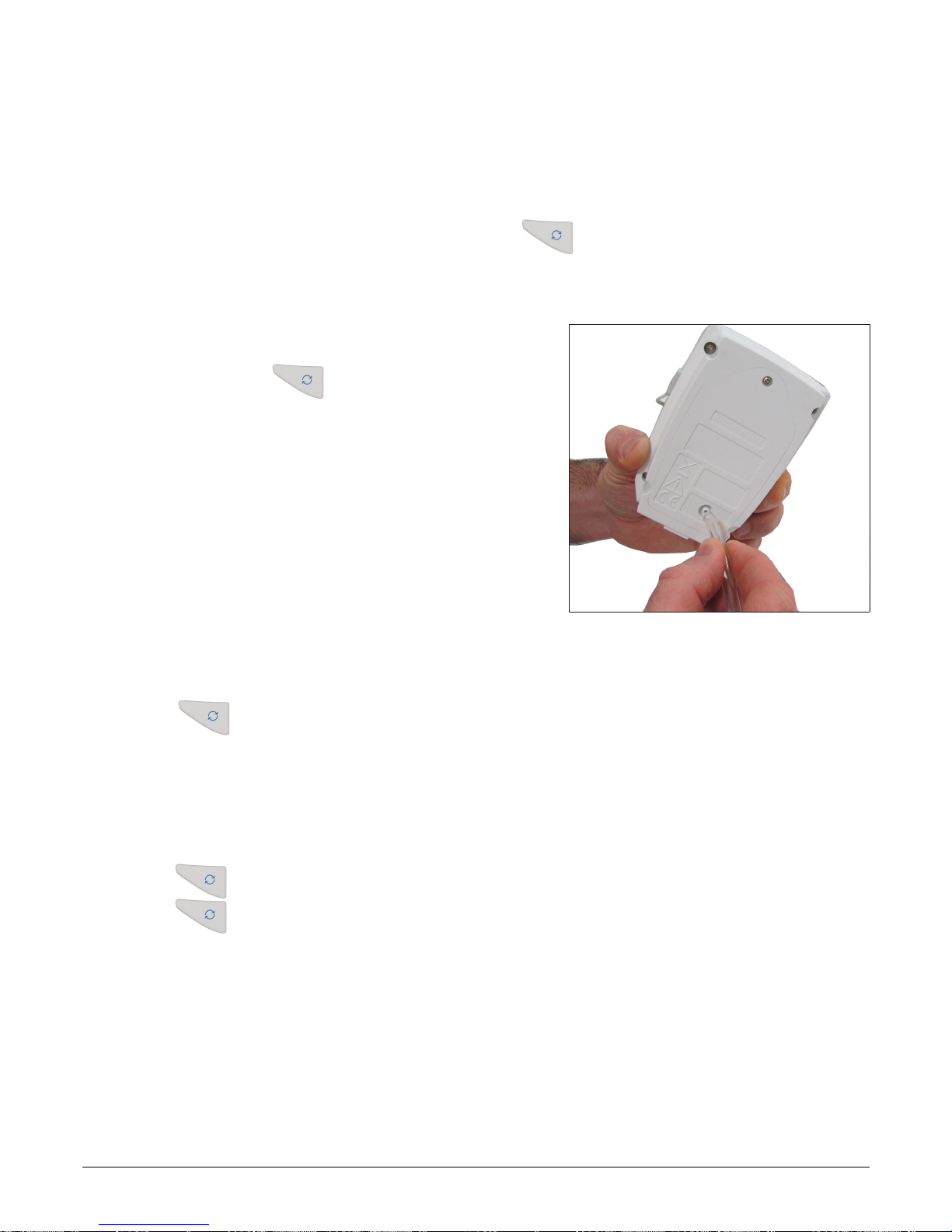
➢ Connect a bottle of CO2 standard gas on the gas connection on
the back of the KCC 320 device with the supplied Tygon® tube.
(see picture)
➢ Generate a gas flow of 30 l/h.
➢ Wait for the measurement stabilization (about 2 minutes).
➢ Check the CO2 values measured by the KCC 320.
➢ If these values are not compliant, it is possible to carry out a
measurement correction with the KILOG software (please see
the KILOG software user manual, “Measurement
correction” chapter).
7.2 KP 320 – KP 321: perform an auto-zero
It is possible to reset the device during a dataset recording:
➢ Unplug the pressure tubes from the device.
➢ Hold for 5 seconds to carry out the auto-zero.
The instrument resets. The screen displays “ ... “
➢ Plug inthe pressure tubes.
The device continues the measurements and the dataset recording.
It is possible to reset the device when values are measured but not recorded:
➢ Unplug the pressure tubes from the device.
➢ Press to display the measurement.
➢ Hold for 5 seconds to carry out the auto-zero.
The instrument resets. The screen displays “ ... “
➢ Plug in the pressure tubes.
The device continues the measurements.
20
CALIBRATION
Page 21
8 ACCESSORIES
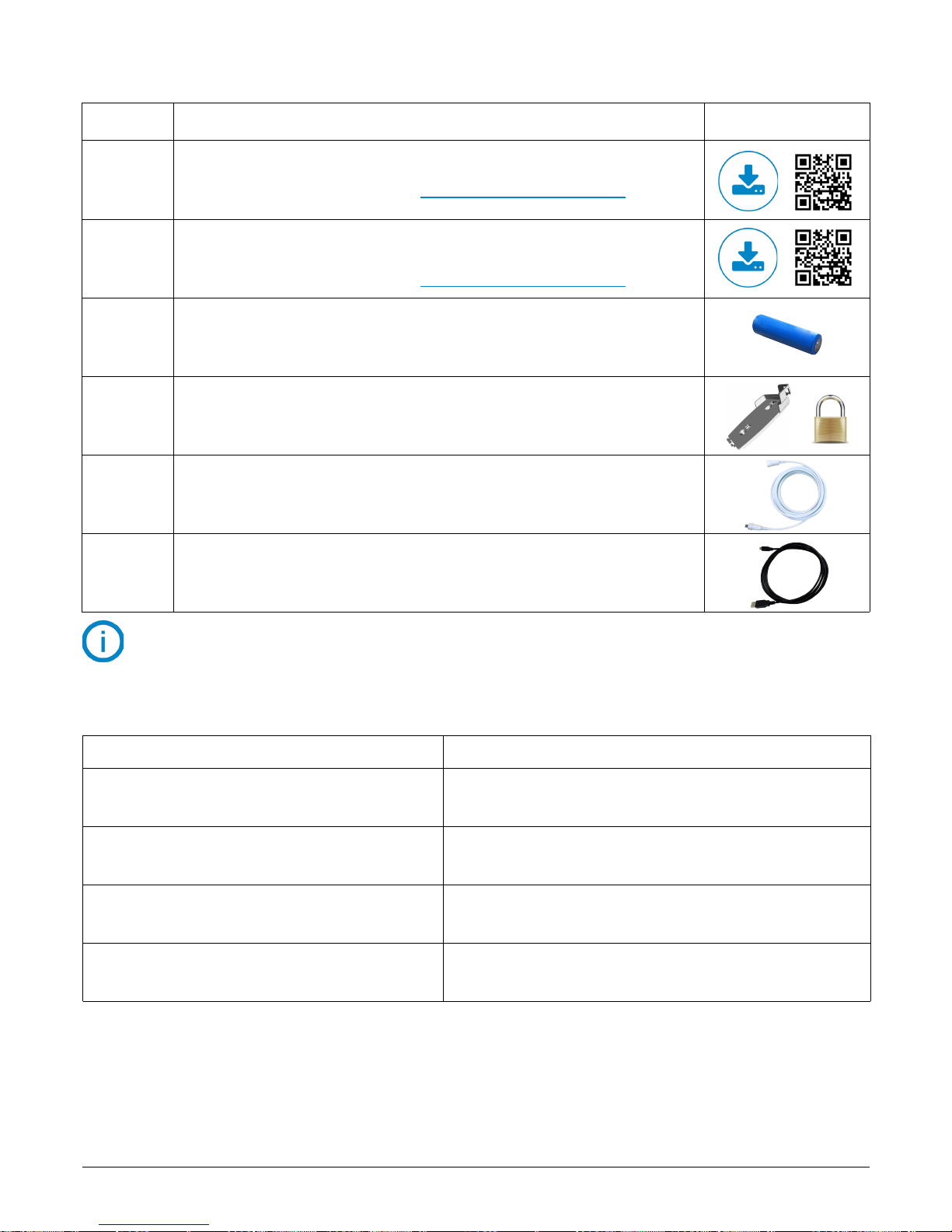
Part No. Description Image
KILOG-LITE
Free basic software for configuration, and data download (tabular & graphical).
Available for download at www.sauermann.us/data-logger
KILOG-3-N
Premium software for configuration, data download, and fast and easy data
saving, processing, and calculations.
Available for download at www.sauermann.us/data-logger
KBL-AA
1 AA lithium 3.6 V battery
(2 batteries are required for class 320 data loggers)
KAV-320
Safety lock wall mount with padlock
KRB-320
Wired extension for KT 320 data loggers probes
In polyurethane, 16' (5 m) length with male and female mini-DIN connectors
(up to 5 extensions can be wired together for greater length requirements)
CK-50
USB / micro-USB cable (connects the data logger to a PC)
Recommended accessories to be used with the data loggers
9 TROUBLESHOOTING
Problem Probable cause and possible solution
No value is displayed, only the icons are present.
The display is set “OFF”. Set it on “ON” with the KILOG software
(see page 15).
The display is completely off* and there is no
communication with the computer.
The battery has to be replaced (see page 19).
The display indicates “- - - -” instead of the measured
value.
The probe is disconnected. Plug it again to the data logger.
There is no Bluetooth® communication with the data
logger.
The Bluetooth® is deactivated. Activate Bluetooth® with the
KILOG software (see page 15).
TROUBLESHOOTING
21
* Only with the KT 320 and KTT 320 data loggers.
Page 22

Page 23

Page 24

BE CAREFUL! Material damages can happen, so please apply the precautionary measures indicated.
NT_US – Class 320 Data Loggers – 16/10/18 – Non-contractual document – We reserve the right to modify the characteristics of our products without prior notice.
 Loading...