

Page 1

PVG 100
Proportional Valve
Technical
Information
Page 2

2
PVG 100 Proportional Valve
Technical Information
Contents
GENERAL
FUNCTION PVG 100
TECHNICAL DATA
MODULES AND CODE
NUMBERS
General ..............................................................................................................................................................4
Valve system ............................................................................................................................................... 4
General features PVG 100 ...................................................................................................................... 4
PVP - Pump side module .......................................................................................................................4
PVB – basic module ..................................................................................................................................4
Actuation modules ...................................................................................................................................4
PVG 100 valve group with open center PVP ........................................................................................5
PVG 100 valve group with closed center PVP ..................................................................................... 5
PVG 100 sectional drawing .........................................................................................................................6
PVG 100 Valve group ..................................................................................................................................... 7
PVH, hydraulic actuation ..............................................................................................................................7
PVM, mechanical actuation ........................................................................................................................8
PVE, reaction time .......................................................................................................................................... 8
PVE, oil consumption and hysteresis ....................................................................................................... 9
PVEO .................................................................................................................................................................... 9
PVEA, PVEH and PVES .................................................................................................................................... 9
PVP 100 inlet modules ................................................................................................................................10
PVP 100 accessories for open center pump side modules ............................................................11
PVB 100 basic modules ..............................................................................................................................11
PVB 32 Basic modules with T0 .................................................................................................................12
PVBZ 32 basic modules with T0 ..............................................................................................................13
Code number for use on PVG 100 ..........................................................................................................14
PVM, mechanical actuation .................................................................................................................14
PVMD, cover for mechanical actuation ...........................................................................................14
PVH, hydraulic actuation ......................................................................................................................14
PVMR friction detent .............................................................................................................................14
PVMF, mechanical float position ........................................................................................................14
PVE for PVG 100 .......................................................................................................................................15
PVLA, suction valve (fitted in PVB) ....................................................................................................16
PVLP, shock and suction valve (fitted in PVB) ...............................................................................17
PVT 100 tank module ............................................................................................................................18
PVTI 100/32 interface module ............................................................................................................18
Assembly kit PVG 100 / PVSI / PVT ....................................................................................................18
Assembly kit PVG 100 /PVTI interface module .............................................................................18
Assembly kit PVB 32 (combo PVG 100) ...........................................................................................18
© 2006 Sauer-Danfoss. All rights reserved. Printed in Europe.
Sauer-Danfoss accepts no responsibility for possible errors in catalogs, brochures and other printed material.
Sauer-Danfoss reserves the right to alter its products without prior notice. This also applies to products
already ordered provided that such alterations aren’t in conflict with agreed specifications. All trademarks in
this material are properties of their respective owners. Sauer-Danfoss and the Sauer-Danfoss logotype are
trademarks of the Sauer-Danfoss Group.
Front cover illustrations: PA270004, F301102, F301196, F301197
520L0720 • Rev. BA • Feb 2007
Drawing: 157-691
Page 3

PVG 100 Proportional Valve
Technical Information
Contents
TECHNICAL
CHARACTERISTICS
DIMENSIONS
HYDRAULIC SYSTEMS
OTHER OPERATING
CONDITIONS
MODULES AND CODE
NUMBERS
General .............................................................................................................................................................19
PVP, pump side module ..............................................................................................................................19
Open center flow rating .............................................................................................................................19
PVB, Basic module ........................................................................................................................................20
PVLP, shock and suction valve ..................................................................................................................22
PVLA, suction valve ......................................................................................................................................22
Valve dimension, PVG 100, open center PVP .....................................................................................23
Valve dimension, PVG100 / 32, closed center .....................................................................................24
Valve dimension, PVG 100, closed center PVP with integrated priority valve ........................25
General dimensions.....................................................................................................................................26
Hydraulic systems ........................................................................................................................................27
Oil .......................................................................................................................................................................28
Mineral oil ..................................................................................................................................................28
Non-flammable fluids ............................................................................................................................28
Biodegradable oils ..................................................................................................................................28
Particle content, degree of contamination .........................................................................................28
Filtration...........................................................................................................................................................29
System filters ............................................................................................................................................29
Internal filters ...........................................................................................................................................29
Standard spools (elec. and mechanical actuation) ...........................................................................30
Standard spools (Hydraulic actuation) .................................................................................................30
Spools for friction detent PVMR ..............................................................................................................31
Spools for mechanical float position PVMF ........................................................................................31
MODULE SELECTION
CHART
ORDER SPECIFICATION
SPECIFICATION SHEET
Module selection chart ..............................................................................................................................32
Order specification ......................................................................................................................................34
Specification Sheet ......................................................................................................................................35
520L0720 • Rev. BB • Jun 2007
3
Page 4

4
520L0720 • Rev. BB • Jun 2007
PVG 100 Proportional Valve
Technical Information
General
GENERAL Valve system
PVG 100 is a hydraulic load sensing valve, designed to fulfill customer requirements.
From a simple load sensing directional valve to an advanced electro hydraulic controlled
load independent proportional valve.
The PVG 100 modular system makes it possible to build up a valve group to fulfill customer
requirements.
The compact external dimensions of the valve remains unchanged whatever combination is
specified.
General features PVG 100
• Load independent flow control
• Oil flow to an individual function is independent of the load on this function
• Oil flow to one function is independent of the load pressure of other functions
• Anti – saturation (flow sharing)
•
In case of anti saturation, pump flow is shared between all functions, independent of load.
• Good regulation characteristics
• Up to 8 PVB 100 basic modules per valve group
• Up to 10 PVB 100/32 basic modules per valve group
• BSP and UNF connection threads
PVP - Pump side module
• Build in load sense relief valve
• System pressure up to 350 bar (5075 psi) • Accumulator gauge connection
• Full Flow dump valve (open center only) • Pressure gauge connection
• Pilot supply shut off • Pilot gauge connection
• Versions
• Open center version for systems with fixed displacement pumps
• Closed center versions for systems with variable displacement pump
• Integrated priority valve
• Integrated pilot supply valve
PVB – basic module
• Integrated pilot operated check valves in A and B work ports for low internal leakage
• Integrated pressure compensator
• Interchangeable spools
• Depending on requirements the basic module can be supplied with :
• Shock/suction valves
• Different spools
Actuation modules
The basic module is always fitted with mechanical actuator PVM, which can be combined
with the following as required:
• Electrical actuator
• PVES – super proportional
• PVEH – proportional high
• PVED – Can-bus interface
• PVEA – proportional, fine
• PVEO – ON/OFF
• PVH, cover for hydraulic actuation
• PVMD, for mechanical actuation
• PVMR, for friction detent
• PVMF, for mechanical detent, float
Page 5

PVG 100 Proportional Valve
Technical Information
Function PVG 100
PVG 100 VALVE GROUP
WITH OPEN CENTER PVPF
When the pump is started and the main spools in the individual basic modules are in the
neutral position, oil flows from the pump, through connection P, across the pressure
matching spool to tank. The oil flow led across the pressure matching spool
determines the pump pressure (stand-by pressure).
When one or more of the main spools are actuated, the highest load pressure is fed
through the shuttle valve circuit to the spring chamber behind the pressure matching
spool, and completely or partially closes the connection to tank.
Pump pressure is applied to the opposite side of the pressure matching spool.
The pressure relief valve will open should the load pressure exceed the set value,
diverting pump flow back to tank.
In a pressure-compensated basic module the compensator maintains a constant
pressure drop across the main spool – both when the load changes and when a module
with a higher load pressure is actuated.
Besides independent flow the other advantage of post-compensated work sections
is the ability to control multifunction operation when flow demand exceeds pump
capacity. This means that all work sections will continue to function regardless of
differences in their load and regardless of the pump flow. The flow relationships specified
between functions will be maintained over the full flow range of the pump.
The shock valves PVLP with fixed setting and the suction valves PVLA on ports A and B
are used for the protection of the individual working function against overload and/or
cavitation.
PVG 100 VALVE GROUP
WITH CLOSED CENTER
PVPV
In load sensing systems the load pressure is led to the pump regulator via the LS connection.
In the neutral position the pump control sets the displacement so that leakage in the
system is compensated for, to maintain the set stand-by pressure.
When a main spool is actuated the pump regulator will adjust the displacement so that
the set differential pressure between P and LS is maintained.
The pressure relief valve in PVP should be set at a pressure of approx. 30 bar [435 psi]
above maximum system pressure (set on the pump or external pressure relief valve).
With post-compensated valves, the rating of the A- and B work-port flow will depend
on the pressure drop across the main spool PVBS. In open center systems, this pressure
drop (standby-pressure) is generated by the volume of pump flow led to tank across the
pressure adjusting spool in the inlet PVPF. Since the pressure drop varies with pump flow
volume led to tank, also the A- and B work-port flow will vary (see further details page 19).
In closed center systems, the pressure drop across the main spool equals the standby
setting of the pump, measured at the P-port of the valve. The A and B work port flow will
remain unchanged as long as the standby is unchanged.
520L0720 • Rev. BB • Jun 2007
5
Page 6

6
520L0720 • Rev. BB • Jun 2007
PVG 100 Proportional Valve
Technical Information
PVG 100
SECTIONAL DRAWING
PVP WITH INTEGRATED
PRIORITY VALVE
Function PVG 100
1. LS relief valve
2. LS connection
3. Priority spool for CF
4. LS connection for steering unit
5. Shuttle valve
6. Pilot operated check valve, POC
7. LS line
8. Logic cartridge for POC
9. Pressure compensator
10. Shock and suction valve, PVLP
11. Main spool, PVBS
12. Max. oil flow adjustment screws for ports A and B
13. LS comp (LS signal sent back to compensators)
Page 7

PVG 100 Proportional Valve
Technical Information
Technical data
PVG 100
VALVE GROUP
The technical data for PVG 100 are typical measured results. For the hydraulic system a
mineral based hydraulic oil with a viscosity of 21 mm2/s [102 SUS] and a temperature of
50°C [122°F] was used.
Port P continuous 350 bar [5075 psi]
Max. pressure
Oil flow, rated
(See characteristics,
see page 20
Spool travel, standard ± 7 mm [±0.28 in]
Spool travel, float
position spool P→B→F
Dead band,
flow control spools
Max. spool leakage
at 100 bar [1450 psi] and
21 mm2/s [102 SUS]
Max. internal leakage with
pilot operated check valve
at 200 bar [2900 psi] and
21 mm2/s [102 SUS]
Oil temperature
(inlet temperature)
Ambient temperature -30 → +60°C [–22 → +140°F]
Oil viscosity
Filtration
(See page 29)
* see also page 10 and 11
Port A/B 350 bar [5075 psi]
Port T, static / dynamic
Port T0, static / dynamic
Port P* 250 l/min [66 US gal/min]
Port A/B, with press. comp. 180 l/min [47.6 US gal/min]
Proportional range 5.5 mm [±0.22 in]
Float position 8 mm [±0.32 in]
Standard ± 1.5 mm [±0.06 in]
A/B → T, without shock valve 20 cm3/min [1.85 in3/min]
A/B → T, with shock valve 25 cm3/min
A/B → T, without shock valve
A/B → T, with shock valve
Recommended temperature 30 → 60°C [86 → 140°F]
Min. temperature -30°C [–22°F]
Max. temperature +90°C [194°F]
Operating range 12 - 75 mm2/s [65 - 347 SUS]
Min. viscosity 4 mm2/s [39 SUS]
Max. viscosity 460 mm2/s [2128 SUS]
Max. contamination
(ISO 4406)
25 bar/40 bar
5 bar/10 bar
1 cm3/min
6 cm3/min
23/19/16 23/19/16
[365/580 psi]
[75/145 psi]
[2.15 in3/min]
[0.06 in3/min]
[0.37 in3/min]
PVH,
HYDRAULIC ACTUATION
Regulation range 5-15 bar [75-220 psi]
Max. pilot pressure 30 bar [435 psi]
Max. pressure on port T 1) 10 bar [145 psi]
1)
The PVRHH remote control (hydraulic joystick) lever should be connected direct to tank.
520L0720 • Rev. BB • Jun 2007
7
Page 8

8
520L0720 • Rev. BB • Jun 2007
PVG 100 Proportional Valve
Technical Information
Technical data
PVM,
MECHANICAL ACTUATION
Regulation range, control lever
stander spool
Regulation range, float
Operating force
PVM + PVMR
Operating force
PVM + PVMF
Control lever positions No.
1)
PVE without voltage
Proportional range ±19.5°
Proportional range
Float position
PVM + PVMD 22 ± 3 N•m
PVM + PVE
PVM + PVH 27 ± 3 Nm
Spool displacement from neutral position 26 Nm [230 lbf·in]
Spool displacement from any other position 16.5 Nm [146 lbf·in]
Spool displacement from neutral position 22 Nm [5.0 lbf·in]
Spool displacement into float position 60 Nm [13.5 lbf·in]
Spool displacement away from float position 28 Nm [6.3 lbf·in]
1)
PVE,
REACTION TIME
PVEO
Voltage Function
Reaction time from
Neutral switch
Neutral switch
Constant voltage
Constant voltage
Hysteresis
1)
Hysteresis is indicated at rated voltage and f = 0.02 Hz for one cycle. A cycle incl. N > full A > N > full B > N.
1)
neutral position
to max. spool travel
Reaction time from
max. spool travel
to neutral position
Reaction time from
neutral position
to max. spool travel
Reaction time from
max. spool travel
to neutral position
Max. 0.235 0.500 0.230 0.230
Rated 0.180 0.320 0.150 0.150
Min. 0.120 0.250 0.120 0.120
Max. 0.175 0.550 0.175 0.175
Rated 0.090 0.400 0.090 0.090
Min. 0.065 0.300 0.065 0.065
Max.
Rated
Min.
Max.
Rated
Min.
rated - 2% 4% <1%
ON/OFF
s
–
–
–
–
–
–
PVEA
Prop.
fine
s
0.500
0.320
0.250
0.250
0.200
0.150
±15.3°
22.3°
Neutral position Max. spool travel
28 ± 3 N•m
[5.0 ± 0.7 lbf·in]
22 ± 3 Nm
[5.0 ± 0.7 lbf·in]
[6.0 ± 0.7 lbf·in]
PVEH
Prop.
high
s
0.200
0.120
0.050
0.100
0.090
0.065
[6.3 ± 0.7 lbf·in]
28 ± 3 Nm
[6.3 ± 0.7 lbf·in]
83 ± 3 Nm
[18.7 ± 0.7 lbf·in]
2 × 6
PVES
Prop.
super
s
0.200
0.120
0.050
0.100
0.090
0.065
Page 9

PVG 100 Proportional Valve
Technical Information
Technical data
PVE,
OIL CONSUMPTION AND HYSTERESIS
Voltage Function
Without voltage Pilot oil flow per PVE Neutral
Locked
With voltage Pilot oil flow per PVE
1 actuation
Actuations
PVEO
ON/OFF
0 l/min
[0 US gal/min]
0.1 l/min
[0.026 US gal/min]
0.002 l
[0.053 US gal/min]
0.7 l/min
[0.185 US gal/min]
PVEA
Prop.
fine
0 l/min
[0 US gal/min]
0.5 l/min
[0.132 US gal/min]
0.002 l
[0.053 US gal/min]
0.75 l/min
[0.200 US gal/min]
PVEH
Prop.
high
0 l/min
[0 US gal/min]
0.1 l/min
[0.026 US gal/min]
0.002 l
[0.053 US gal/min]
1.1 l/min
[0.290 US gal/min]
PVES
Prop.
super
0 l/min
[0.106 US gal/min]
0.2 l/min
[0.053 US gal/min]
0.002 l
[0.053 US gal/min]
1.1 l/min
[0.2906 US gal/min]
PVEO
PVEA, PVEH AND PVES
PVEO
rated 12 V DC 24 V DC
Supply voltage U
Current consumption at rated voltage 0.65 A @ 12 V 0.33 A @ 24 V
Input impedance in relation to 0.5 • U
Power consumption 8 W
Supply voltage U
Current consumption at rated voltage
Signal voltage
Signal currrent at rated voltage 0.25 mA to 0.70 mA
Input impedance in relation to 0.5 • U
Input capacitor
Power consumption
For detailed information, see PVE actuator catalog, 520L0553
DC
DC
range 11 V to 15 V 22 V to 30 V
max. ripple 5%
DC
rated 11 V to 32 V
range 11 V to 32 V
max. ripple 5%
PVEH/PVES (PVEA) 0.57 (0.28) A @ 12 V 0.3 (0.15) A @ 24 V
neutral
A-port ↔ B-port
DC
PVEH/PVES (PVEA) 7 (3.5) W
12 KΩ
PVEA, PVEH and PVES
0.5 •U
DC
0.25 • UDC to 0.75 • U
12 KΩ
100 ηF
DC
520L0720 • Rev. BB • Jun 2007
9
Page 10

10
520L0720 • Rev. BB • Jun 2007
PVG 100 Proportional Valve
Technical Information
PVP 100 INLET MODULES
Modules and code numbers
Symbol Description PVPF
Open center pump side module for pumps
with fixed displacement
Max. pump flow 250 l/min [66 US gal/min]
With pilot supply for electrical actuation
With pilot gauge port
Open center pump side module for pumps
with fixed displacement
Max. pump flow 250 l/min [66 US gal/min]
With pilot supply for electrical actuation
With pilot gauge port
Accumulator port and facility for pilot shut
off.
Symbol Description PVPV Port size Code number
12 bar
spring*
20 bar
spring*
12 bar
spring*
20 bar
spring*
12 bar
spring*
20 bar
spring*
12 bar
spring*
20 bar
spring*
Port size
G1
1 5/16 -12 UN
G1
1 5/16 -12 UN
Code number
161B5110
161B5112
161B5510
161B5512
161B5140
161B5142
161B5540
161B5542
Closed center pump side module for pumps
with variable displacement
Max. pump flow 250 l/min [66 US gal/min]
With pilot supply for electrical actuation
With pilot gauge port
Closed center pump side module for pumps
with variable displacement
Max. pump flow 250 l/min [66 US gal/min]
With pilot supply for electrical actuation
With pilot gauge port
Accumulator port and facility for pilot shut of off
Closed center pump side module for pumps
with variable displacement
Max. pump flow 200 l/min [52.8 US gal/min]
With integrated priority function
Max. CF-flow 60 l/min [15.9 US gal/min]
With pilot supply for electrical actuation
G1
5
1
/16 -12 UN
G1
1 5/16 -12 UN
.
P = G3/4
T = G 1
P = 1 1/16 -12 U
T = 1 5/16 -12 UN
161B5111
161B5511
161B5141
161B5541
161B5211
161B5611
* Spring for pressure matching spool - PVPF open center only. For further details see page 19.
Page 11

PVG 100 Proportional Valve
Technical Information
Modules and code numbers
PVP 100 ACCESSORIES FOR PUMP SIDE MODULES
Symbol Description Code number
Dummy spool 155G5041*
12 V
PVPE electrically actuated unloading valve.
Normally open solenoid valve
24 V
155G5052*
155G5054*
12 V
PVPP electrically actuated pilot shut off.
Normally closed solenoid valve
* For PVPF open center inlets only
PVB 100 BASIC MODULE
Symbol Description PVB
Post compensated
24 V
Port size Without
PVLP
G 3/4
11/16 - 12 UN
161B6250
161B6650
800572719
800572819
Code number
With
PVLP
161B6260
161B6660
520L0720 • Rev. BB • Jun 2007
Post compensated
With pilot operated check
valves on work port A
and B
G 3/4
11/16 - 12 UN
161B6252
161B6652
161B6262
161B6662
11
Page 12

12
520L0720 • Rev. BB • Jun 2007
PVG 100 Proportional Valve
Technical Information
Modules and code numbers
PVB 32 BASIC MODULE WITH T0
Symbol Description PVB
Without load drop check
valve and pressure compensator.
Can be used where load holding
valves prevent oil from floating
back through the channel P.
Code number 157B.....
No facility for Facility for
shock valve for shock valve
BSP SAE BSP SAE
6010 6410 - -
Connection: A and B-port G 1/2 [ 7/8 in - 14]
Load drop check valve
Pre compensated
Pre compensated
Adjustable LS A/B limiting
valves.
External LS connection
port A/B.
Also used for float
position spools.
6110 6909 6140 6904
6210 6922 6240 6906
6213 6613 6243 6643
Page 13
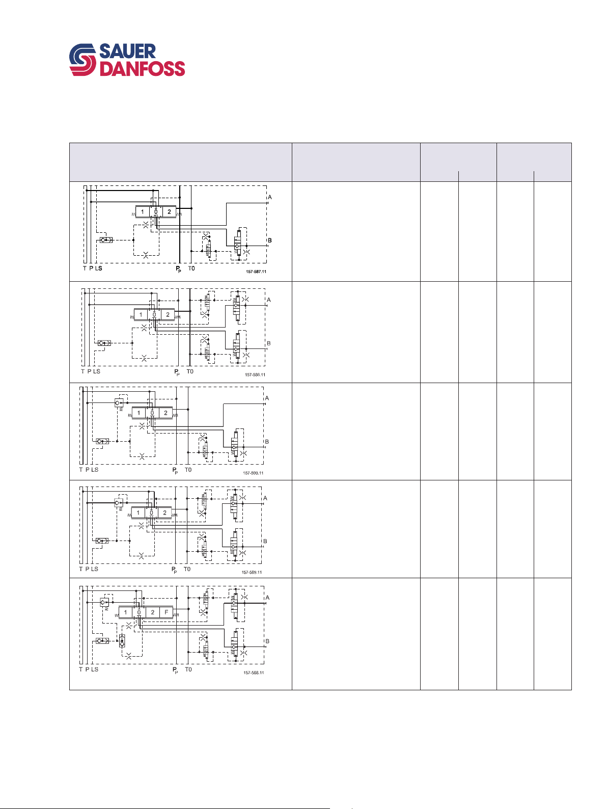
PVBZ 32 BASIC MODULE
PVG 100 Proportional Valve
Technical Information
Modules and code numbers
Symbol Description PVBZ
Without compensator and load
drop check valve
With pilot operated check valves
on work port B
Max. work port pressure =
210 bar [3045 psi]
Without compensator and load
drop check valve
With pilot operated check valves
on work port A and B
Max. work port pressure =
210 bar [3045 psi]
Pre compensated
With pilot operated check valves
on work port B
Compensated work port flow A/B =
100 l/min [26.4 US gal/min]
Max. work port pressure =
210 bar [3045 psi]
Without thermal
relief valve 157B...
BSP SAE
6051 6451 - -
6052 6452
6251 6651 6261 6661
With thermal
relief valve 157B...
BSP SAE
- -
Connection: A and B-port G 1/2 [ 7/8 in - 14]
Seal kit for PVBZ 157B6989
520L0720 • Rev. BB • Jun 2007
Pre compensated
With pilot operated check valves
on work port A and B
Compensated work port flow A/B =
100 l/min [26.4 US gal/min]
Max. work port pressure =
210 bar [3045 psi]
Pre compensated
With pilot operated check valves
on work port A and B
LSA/B shuttle valve for float and
shuttle pin
Compensated work port flow A/B =
100 l/min [26.4 US gal/min]
Max. work port pressure =
210 bar [3045 psi]
6252 6652 6262 6662
- - 6266 6666
13
Page 14
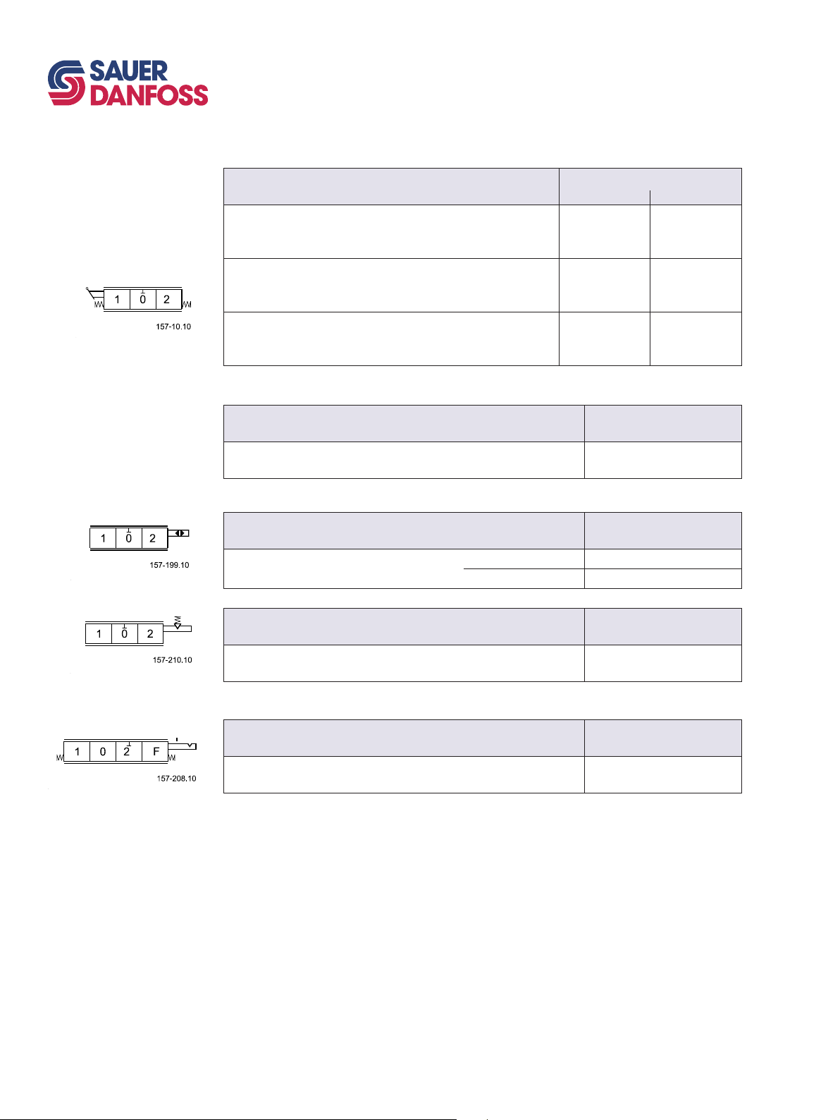
14
520L0720 • Rev. BB • Jun 2007
PVG 100 Proportional Valve
Technical Information
Modules and code numbers
CODE NUMBERS FOR USE
ON PVG 100
157B....
PVM
Mechanical actuation
PVM,
Standard, spring centered
Individual oil flow adjustment to ports A an B
PVM
Without actuation lever and base.
Shaft for mounting of actuation lever.
PVM
A standard, without actuation lever.
With base for mounting of actuation lever.
Code number for the anodized version of 157B3171 is 157B3184
PVMD
Cover for mechanical actuation
PVMD*
Cover for purely mechanically operated valve
PVH
Hydraulic actuation
PVH* G 1/4
Cover for hydraulic remote control 9/16 -18 UNF
22.5°
37.5°
22.5°
37.5°
Code number
w. stopscrews w/o stop screws
157B3171
157B3172
157B3173 157B3193
157B3175
157B3174
Code number
Code number
157B3191
157B3192
157B3195
157B3194
157B0001
157B0008
157B0007
PVMR
Friction detent
PVMR*
Friction detent
PVMF
Mechanical float position
PVMF*
Mechanical float position lock, float B-port
* Opposite of the PVM
Code number
157B0015
Code number
157B0005
Page 15
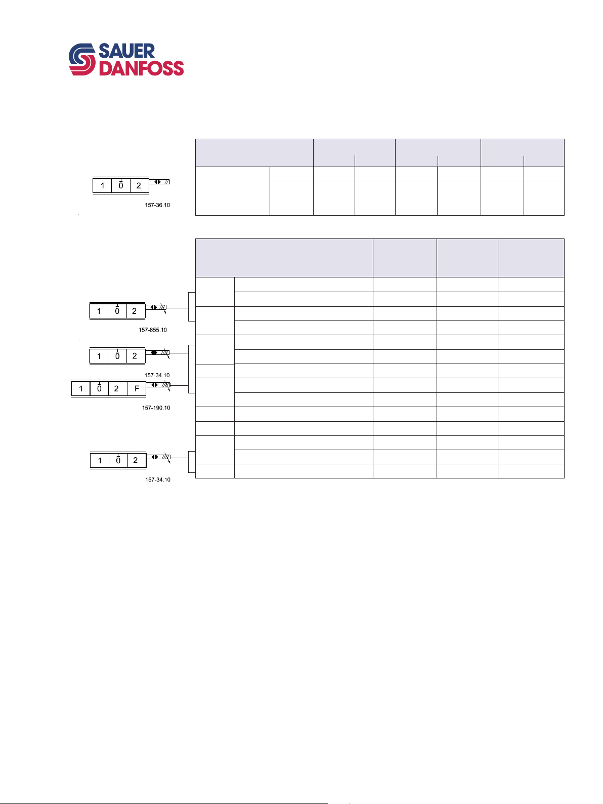
PVG 100 Proportional Valve
Technical Information
Modules and code numbers
CODE NUMBERS FOR USE
ON PVG 100
157B....
PVE for PVG 100
PVEO, ON/OFF actuation
Code no. 157B....
ON/OFF
PVEO
PVEA/PVEH/PVES, proportional actuation
PVEA
PVEA-DI
PVEH
PVEH-F
PVEH-DI
PVEP Standard, active fault monitoring - - 4752
PVEP-F Standard, active fault monitoring - - 4793
PVES
PVED-CC Can-bus interface Not available 4943 4944
Standard, active fault monitoring Not available 4734 4792
Standard, passive fault monitoring Not available 4735 -
Standard, active fault monitoring Not available 4736 4796
Standard, passive fault monitoring Not available 4737 -
Standard, active fault monitoring 4032 4034 4092
Standard, passive fault monitoring 4033 4035 -
Float, active fault monitoring Not available 4338 4398
Standard, active fault monitoring Not available 4036 4096
Standard, passive fault monitoring Not available 4037 -
0% hysteresis, active fault monitoring 4832 4834 4892
0% hysteresis, passive fault monitoring 4833 4835 -
ON/OFF
with ramp
Code no. 157B....
Hirschmann
12 V 24 V
4216 4228 4901 4902 4291 4292
4217 4229 4903 4904 - -
Hirschmann
connector
11 - 32 V
AMP
12 V 24 V
connector
11 - 32 V
AMP
Deutsch
12 V 24 V
Deutsch
connector
11 - 32 V
520L0720 • Rev. BB • Jun 2007
15
Page 16
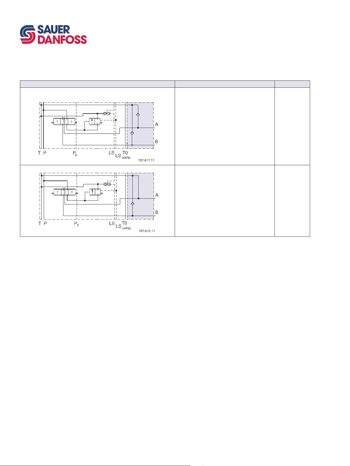
16
520L0720 • Rev. BB • Jun 2007
PVG 100 Proportional Valve
Technical Information
Modules and code numbers
PVLA, SUCTION VALVE (FITTED IN PVB)
Symbol Description
Code number
Suction valve for port A and/or B 157B2001
Cap for connecting the nonactive port to tank,
when using a single acting spool
157B2002
Page 17
PVG 100 Proportional Valve
Technical Information
Modules and code numbers
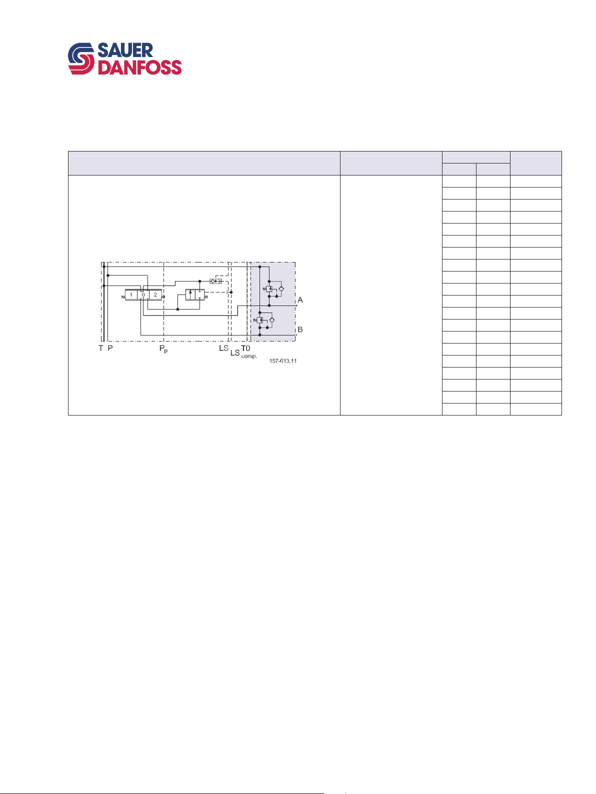
PVLP,
SHOCK AND SUCTION VALVE (FITTED IN PVB)
Symbol Description
Shock and suction
valve for port A and B.
(Not adjustable)
Setting Code
numberbar [psi]
32 460 157B2032
50 725 157B2050
63 914 157B2063
80 1160 157B2080
100 1450 157B2100
125 1813 157B2125
140 2031 157B2140
150 2175 157B2150
160 2320 157B2160
175 2538 157B2175
190 2755 157B2190
210 3045 157B2210
230 3335 157B2230
240 3480 157B2240
250 3625 157B2250
265 3843 157B2265
280 4061 157B2280
300 4351 157B2300
320 4641 157B2320
350 5075 157B2350
520L0720 • Rev. BB • Jun 2007
17
Page 18
18
520L0720 • Rev. BB • Jun 2007
PVG 100 Proportional Valve
Technical Information
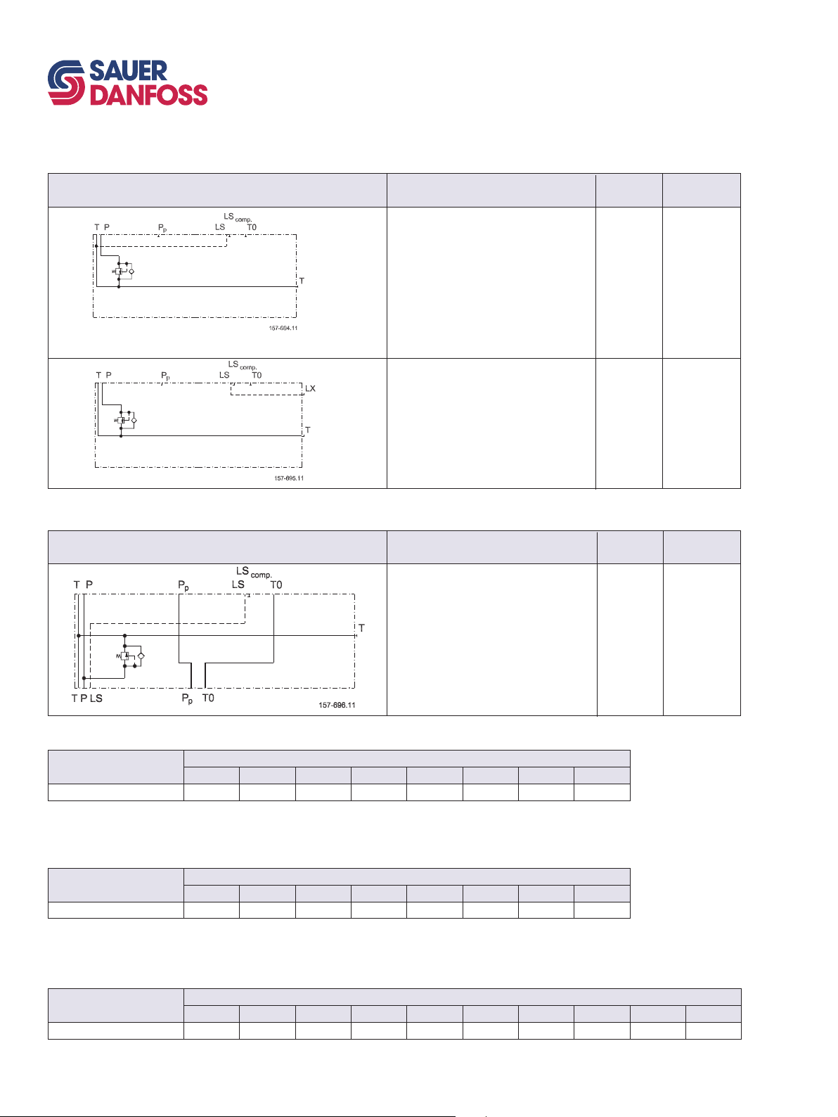
PVT 100 TANK MODULE
Symbol
Modules and code numbers
Description
Port size
Code number
PVTI 100/32 INTERFACE MODULE
Symbol
PVT
Without active elements
With T-port
PVLP shock valve facility
PVT
Without active elements
With T-port
PVLP shock valve facility
With LX connection G1/4 [ 9/16 in – 18 UNF
PVTI
Without active elements
With T-port
PVLP shock valve facility
Description
G 11/4
15/8 - UN
G 11/4
15/8 - UN
G 11/4
15/8 - UN
Portsize
161B2500
161B2520
161B2505
161B2525
Code number
161B2200
161B2220
ASSEMBLY KIT PVG 100 PVSI / PVT
Description
Tie bolts and seals 8001 8002 8003 8004 8005 8006 8007 8008
1 PVB 2 PVB 3 PVB 4 PVB 5 PVB 6 PVB 7 PVB 8 PVB
Code number 161B….
ASSEMBLY KIT PVG 100 / PVTI INTERFACE MODULE
Description
Tie bolts and seals 8021 8022 8023 8024 8025 8026 8027 8028
1 PVB 2 PVB 3 PVB 4 PVB 5 PVB 6 PVB 7 PVB 8 PVB
Code number 161B….
ASSEMBLY KIT PVB 32
Description
Tie bolts and seals 8000 8001 8002 8003 8004 8005 8006 8007 8008 8009
1 PVB 2 PVB 3 PVB 4 PVB 5 PVB 6 PVB 7 PVB 8 PVB 9 PVB 10 PVB
Code number 157B….
Page 19

PVG 100 Proportional Valve
Technical Information
Technical characteristics
GENERAL
PVP,
PUMP SIDE MODULE
The characteristics in this catalog are typical measured results.
During measuring a mineral based hydraulic oil with a viscosity of 21 mm2/s [102 SUS] at
a temperature of 50°C [122°F] was used.
Pressure relief valve characteristic
in PVP
The pressure relief valve is set at an oil
flow of 15 l/min [4.0 US gal/min].
Setting range:
30 to 350 bar [435 to 5075 psi]
Neutral flow pressure in PVP,
open center
OPEN CENTER FLOW
RATING
As mentioned on page 5, the flow rating of the different main spools will depend on
the standby pressure available. In open center systems, the standby pressure equals the
pressure drop P->T, see above diagram. A pump flow of 150 l/min led to tank across the
pressure adjusting spool, will generate a standby pressure of app. 15 bar (PVP with 12 bar
spring). The according main spool flow ratings will correspond to the curves on page 20
For PVPs with a 20 bar spring, the standby pressure available will be 20 bar or higher.
Hence the according main spool flow ratings will correspond to page 20.
520L0720 • Rev. BB • Jun 2007
19
Page 20
20
520L0720 • Rev. BB • Jun 2007
PVG 100 Proportional Valve
Technical Information
Technical characteristics
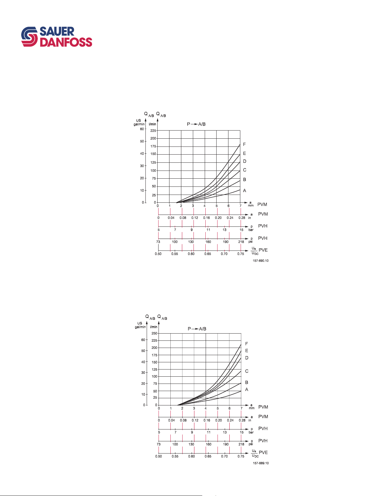
PVB,
BASIC MODULE
PVB with pressure compensation, closed center PVP
Oil flow as a function of spool travel for spools A to F
Set pressure difference between pump pressure and LS signal = 15 bar bar [218 psi]
measured at the P-port of the valve. For spool size reference see page 30 and 31.
PVB with pressure compensation, closed center PVP
Oil flow as a function of spool travel for spools A to F
Set pressure difference between pump pressure and LS signal = 20 bar bar [290 psi]
measured at the P-port of the valve. For spool size reference see page 30 and 31.
Page 21
PVG 100 Proportional Valve
Technical Information
Technical characteristics
PVB,
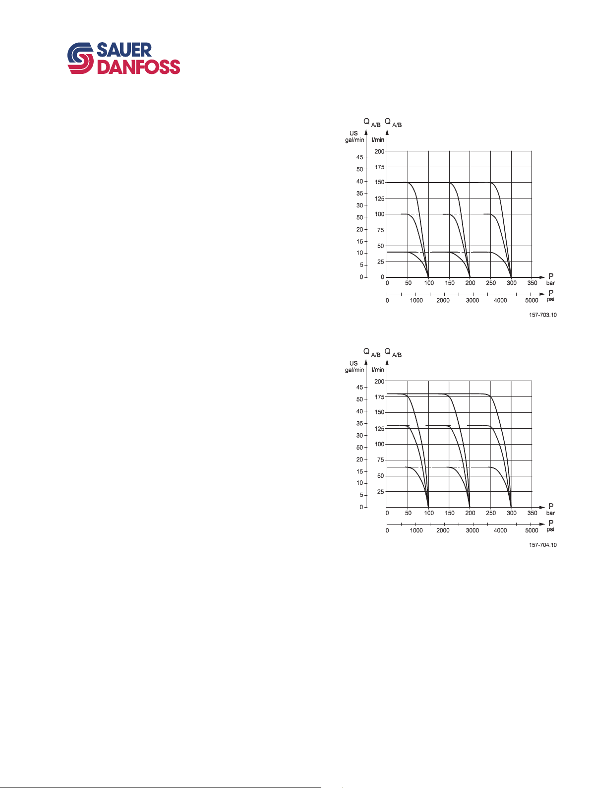
BASIC MODULE
(CONTINUED)
Oil flow at LS pressure limiting,
pressure compensated PVB
for spools A, C and E
Oil flow at LS pressure limiting,
pressure compensated PVB
for spools B, D and F
520L0720 • Rev. BB • Jun 2007
21
Page 22
22
520L0720 • Rev. BB • Jun 2007
PVG 100 Proportional Valve
Technical Information
Technical characteristics
PVLP,
SHOCK AND
SUCTION VALVE
PVLA,
SUCTION VALVE
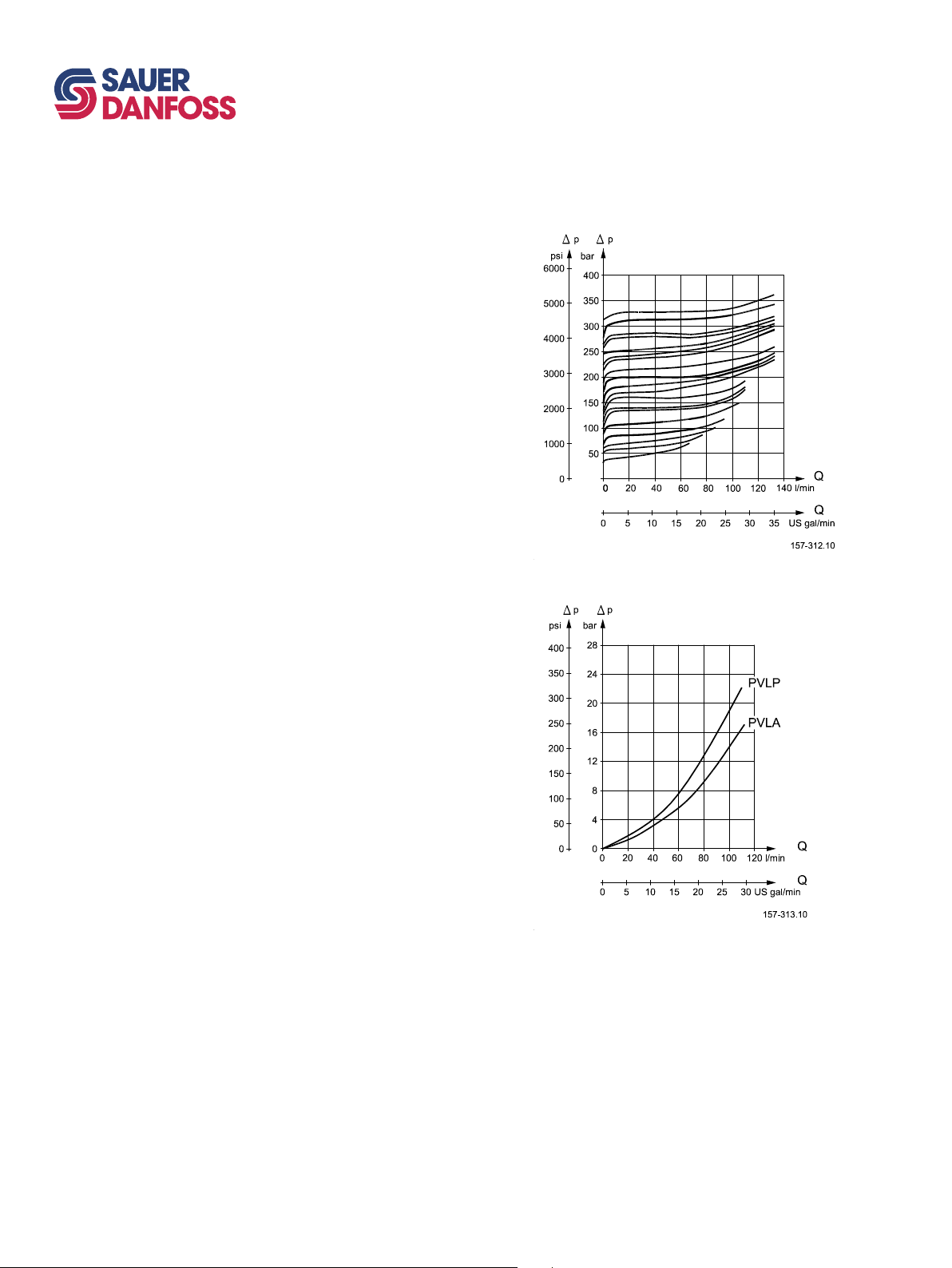
PVLP, shock valve
PVLP is set at an oil flow of 10 l/min
[2.6 US gal/min].
The shock valve PVLP is designed to
absorb shock effects. Consequently, it
should not be used as a pressure relief
valve.
PVLP/PVLA, suction valve
Page 23
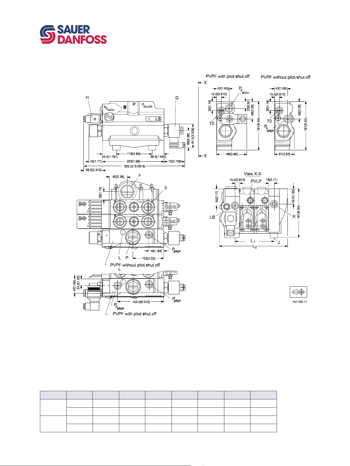
VALVE DIMENSION,
PVG 100, OPEN CENTER
PVPF
PVG 100 Proportional Valve
Technical Information
Dimensions
Pp accumulator connection : G1/4 [9/16 in - 18 UNF]
LS connection : G1/4 [9/16 in - 18 UNF]
P gage connection : G1/4 [9/16 in - 18 UNF]
T0 port connection : G1/4 [9/16 in - 18 UNF]
Pp gage connection : G1/4 [9/16 in - 18 UNF]
P: Pump port connection; G1 [15/16 in - 12 UNF]
1 PVB 2 PVB 3 PVB 4 PVB 5 PVB 6 PVB 7 PVB 8 PVB
mm 80 128 176 224 272 320 368 416
L1
[in] [3.15] [5.04] [6.93] [8.82] [10.71] [12.60] [14.49] [16.38]
mm 176 224 272 320 368 416 464 512
L2
[in] [6.93] [8.82] [10.71] [12.60] [14.49] [16.38] [18.27] [20.16]
520L0720 • Rev. BB • Jun 2007
G: PVPE unloading valve
F : Tank port connection; G 11/4 [1 5/8 in - 12 UNF]
H: PVPP pilot shut off valve
J : Mounting thread; M12 x 14 mm deep.
It is recommended ton only use 3 of 4 mounting
holes provided.
K : LX connection : G1/4 [9/16 in - 18 UNF]
L : LS relief valve
23
Page 24
24
520L0720 • Rev. BB • Jun 2007
PVG 100 Proportional Valve
Technical Information
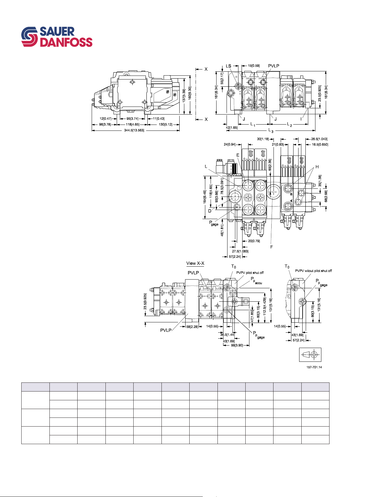
VALVE DIMENSION
PVG 100/32, CLOSED
CENTER PVPV
Dimensions
LS connection : G1/4 [9/16 in - 18 UNF]
P gage connection : G1/4 [9/16 in - 18 UNF]
T0 port connection : G1/4 [9/16 in - 18 UNF]
Pp gage connection : G1/4 [9/16 in - 18 UNF]
Pp accumulator connection : G1/4 [9/16 in - 18 UNF]
D : Pump port connection; G1 [1 5/16 in - 12 UNF]
E : Port A and B PVB 100; G 3/4 [1 1/16 in - 12 UNF]
F : Tank port connection; G11/4 [1 5/8 in - 12 UNF]
H : Port A and B PVB 32; G1/2 [7/8 in - 14 UNF]
I : Mounting thread ; M8 x 15 mm deep [5/16 in - 18 UNC]
J : Mounting thread; M12 x 14 mm deep
L : LS relief valve
1 PVB 2 PVB 3 PVB 4 PVB 5 PVB 6 PVB 7 PVB 8 PVB 9 PVB 10 PVB
mm 80 128 176 224 272 320 368 416 - -
L
1
[in] [3.15] [5.04] [6.93] [8.82] [10.71] [12.60] [14.49] [16..38] - -
mm 100 148 196 244 292 340 388 436 484 532
L2
[in] [3.94] [5.83] [7.72] [9.61] [11.50] [13.39] [15.28] [17.16] [19.05] [20.94]
mm - 245 293 341 389 437 485 533 581 629
L
3
[in] - [9.64] [11.54] [13.43] [15.31] [17.20] [19.09] [20.98] [22.87] [24.76]
It is recommended not to exceed 10 PVB 100/32 in a valve group.
Page 25
2
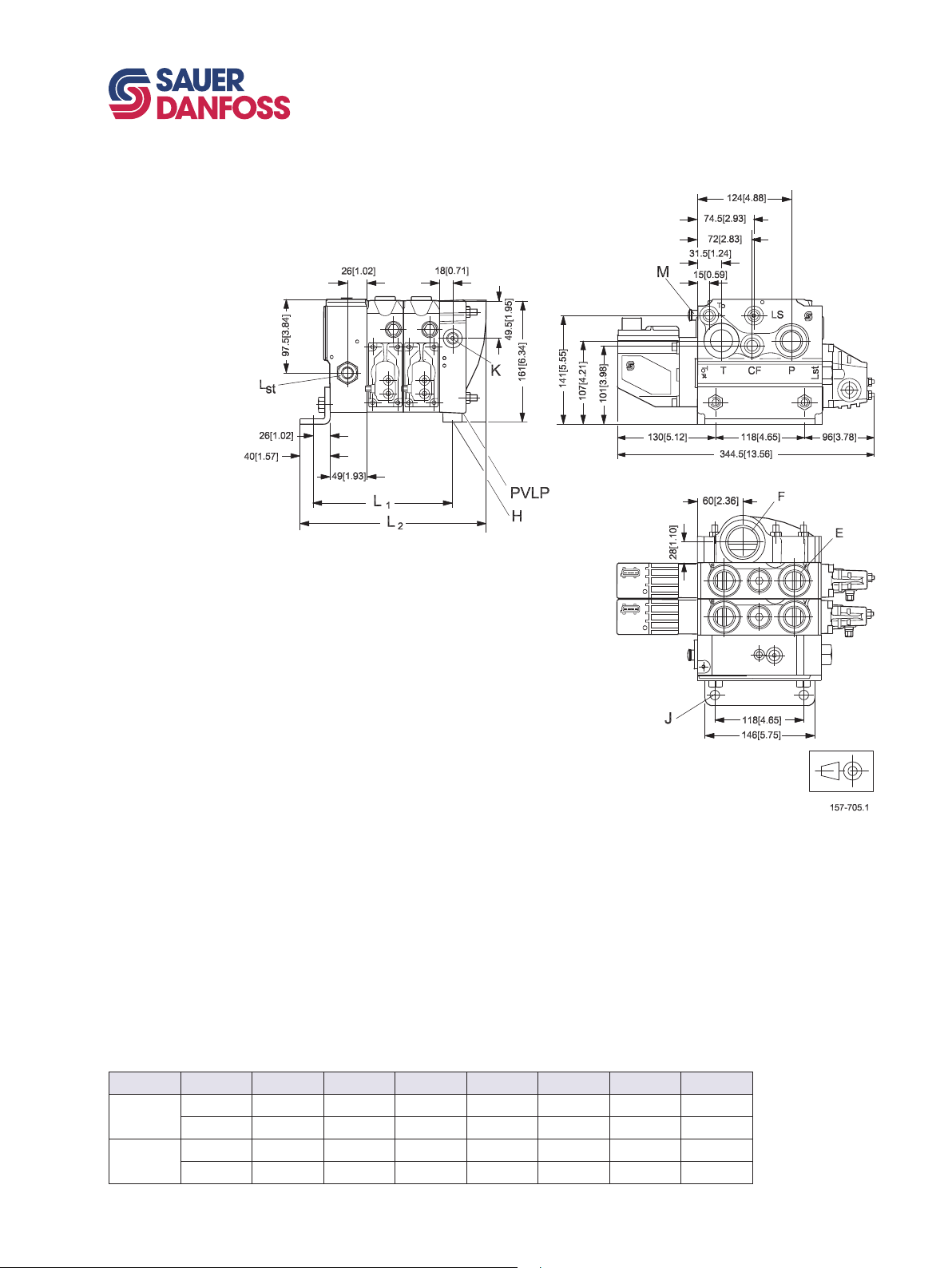
VALVE DIMENSION
PVG 100, CLOSED
CENTER PVP WITH
INTEGRATED PRIORITY
VALVE
PVG 100 Proportional Valve
Technical Information
Dimensions
CF connection : G 1/2 [3/4 in - 16 UNF]
LS connection : G1/4 [9/16 in - 18 UNF]
P gage connection : G1/4 [7/16 in - 24 UNF]
T0 port connection : G1/4 [9/16 in - 18 UNF]
Pp gage connection : G1/4 [7/16 in - 24 UNF]
P pump port connection; G3/4 [1 1/16 in - 12 UNF]
Lst: LS connection for steering unit; G1/4 [9/16 in - 18 UNF]
E : Port A and B PVB 100; G3/4 [1 1/16 in - 12 UNF]
H : Mounting thread : M12 x 14 mm deep
J : Mounting bracket with holes for M12 screws
K : LX connection : G1/4 [9/16 in - 18 UNF]
M : LS relief valve
F : G1/4 [1 1/16 in]
1 PVB 2 PVB 3 PVB 4 PVB 5 PVB 6 PVB 7 PVB 8 PVB
mm 140 188 236 284 332 380 428 476
L
1
[in] [5.51] [5.12] [9.29] [11.18] [9.13] [14.96] [16.85] [18.74]
mm 198 246 294 342 390 438 486 534
L2
[in] [7.80] [9.69] [11.57] [13.46] [15.35] [17.24] [19.13] [21.02]
520L0720 • Rev. BB • Jun 2007
25
Page 26
26
520L0720 • Rev. BB • Jun 2007
PVG 100 Proportional Valve
Technical Information
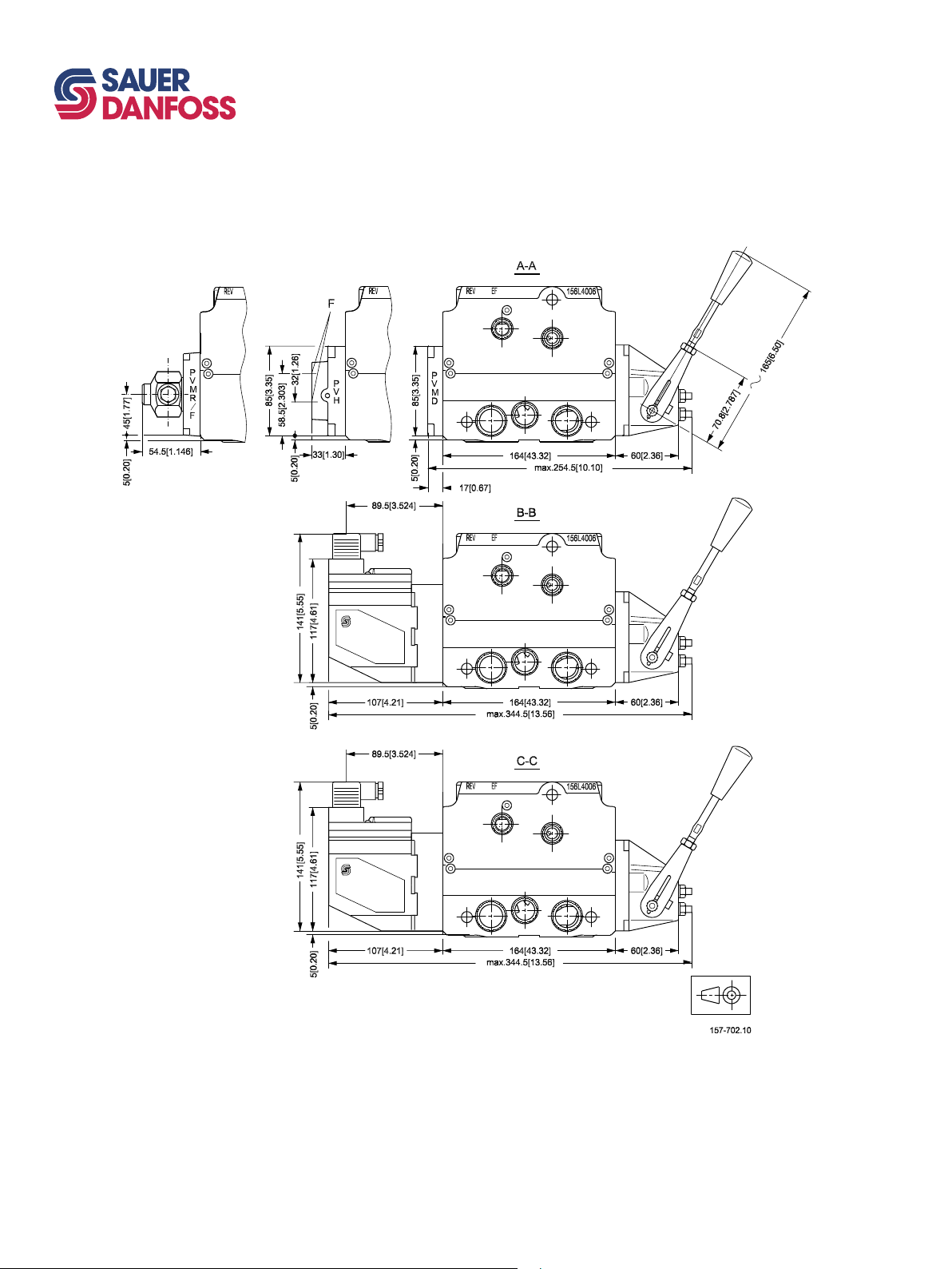
GENERAL DIMENSIONS
Dimensions
Page 27
PVG 100 Proportional Valve
Technical Information
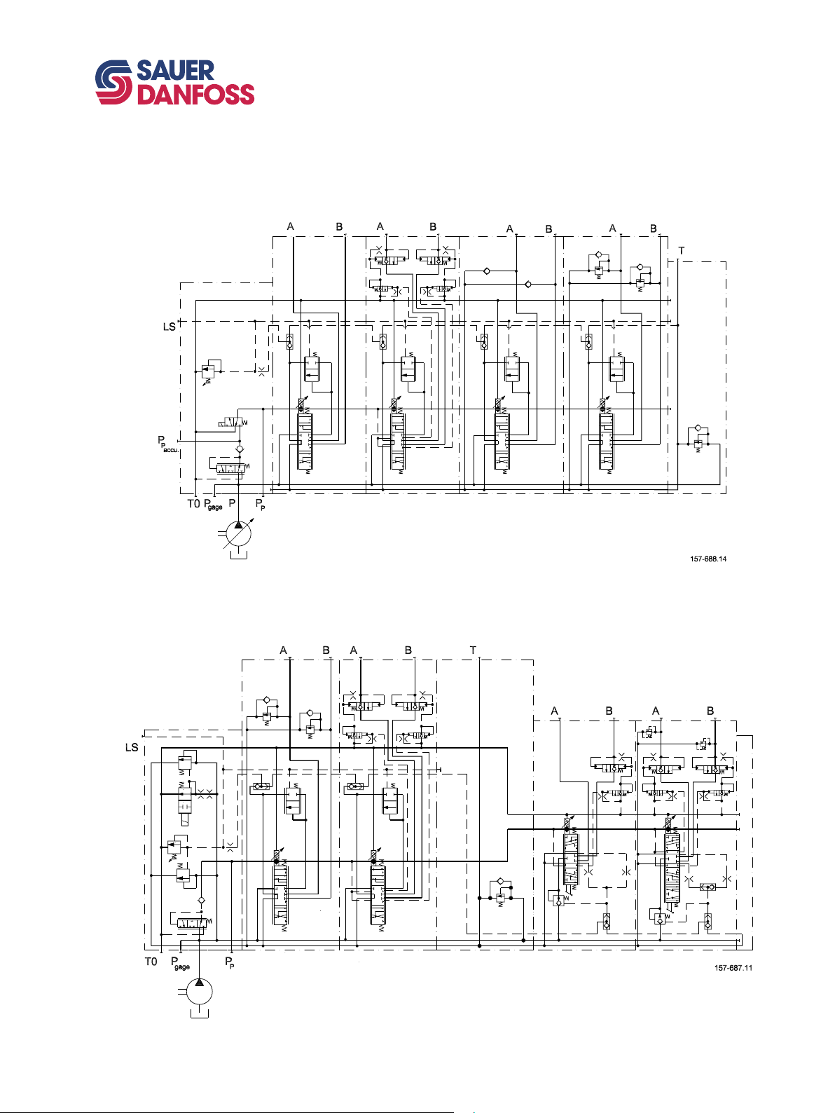
Hydraulic systems
ELECTRICALLY ACTUATED PVG 100 VARIABLE DISPLACEMENT PUMP
PVB 100 WITH INTEGRATED PILOT OPERATED CHECK VALVES
ELECTRICALLY ACTUATED PVG 100/32 FIXED DISPLACEMENT PUMP
PVB 100/32 WITH INTEGRATED PILOT OPERATED CHECK VALVES
520L0720 • Rev. BB • Jun 2007
27
Page 28

28
520L0720 • Rev. BB • Jun 2007
PVG 100 Proportional Valve
Technical Information
Other operating conditions
OIL
The main duty of the oil in a hydraulic system is to transfer energy; but it must also
lubricate the moving parts in hydraulic components, protect them against corrosion, and
transport dirt particles and heat out of the system. It is therefore important to choose the
correct oil with the correct additives. This gives normal operation and long working life.
Mineral oil
For systems with PVG 100 valves Sauer-Danfoss recommends the use of mineral-based
hydraulic oil containing additives: Type HLP (DIN 51524) or HM (ISO 6743/4).
Non-flammable fluids
Phosphate-esters (HFDR fluids) can be used without special precautions. However,
dynamic seals must be replaced with FPM (Viton) seals.
So please contact the Sauer-Danfoss Sales Organization if the PVG 100 valve is to be
used with phosphate-esters.
The following fluids should only be used according to agreement with the Sales
Organization for Sauer-Danfoss:
• Water-glycol mixtures (HFC fluids)
• Water-oil emulsions (HFB fluids)
• Oil-water emulsions (HFAE fluids)
Biodegradable oils
PVG 100 valves can be used in systems with rapeseed oil. The use of rapeseed oil is
conditioned by
- complying with the demands on viscosity, water content, temperature and filtering
etc. (see chapters below and technical data page 7).
- adapting the operating conditions to the directions of the oil supplier.
PARTICLE CONTENT,
DEGREE OF
CONTAMINATION
Before using other biodegradable fluids, please consult the Sauer-Danfoss Organization.
Oil filtration must prevent particle content from exceeding an acceptable level, i.e. an
acceptable degree of contamination.
Maximum contamination for PVG 100 is 23/19/16 (see ISO 4406. Calibration in
accordance with the ACFTD method).
In our experience a degree of contamination of 23/19/16 can be maintained by using a
filter fineness as described in the next section.
Page 29

PVG 100 Proportional Valve
Technical Information
Other operating conditions
FILTRATION Effective filtration is the most important precondition in ensuring that a hydraulic system
performs reliably and has a long working life. Filter manufacturers issue instructions and
recommendations. It is advisable to follow them.
System filters
Where demands on safety and reliability are very high a pressure filter with bypass and
indicator is recommended. Experience shows that a 10 µm nominal filter (or finer) or a
20 µm absolute filter (or finer) is suitable.
It is our experience that a return filter is adequate in a purely mechanically operated
valve system.
The fineness of a pressure filter must be selected as described by the filter manufacturer
so that a particle level of 23/19/16 is not exceeded.
The filter must be fitted with pressure gauge or dirt indicator to make it possible to
check the condition of the filter.
In systems with differential cylinders or accumulators the return filter must be sized to
suit the max. return oil flow. Pressure filters must be fitted to suit max. pump oil flow.
Internal filters
The filters built into PVG 100 are not intended to filter the system but to protect
important components against large particles. Such particles can appear in the system
as a result of pump damage, hose fracture, use of quick-couplings, filter damage, starting
up, contamination, etc.
The filter in the electrical actuator PVE protecting the solenoid valves has a mesh of
150 µm.
Bursting pressure drop for internal filters is 25 bar [360 psi].
520L0720 • Rev. BB • Jun 2007
29
Page 30
30
520L0720 • Rev. BB • Jun 2007
PVG 100 Proportional Valve
Technical Information
Modules and code numbers
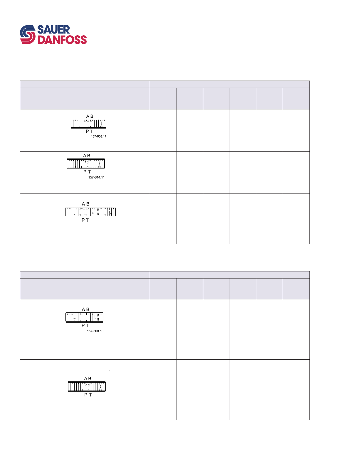
STANDARD SPOOLS (ELECTRICAL AND MECHANICAL ACTUATION)
Code number 161B....
Throttled, open neutral position
Symbol
4-way, 3-position
Closed neutral position
4-way, 3-position
A
40
[10,6]
7022 7023 7024 7025 7026 7027
7122 7123 7124 7125 7126 7127
Pressure compensated flow l/min [US gal/min]
[17,2]
65
B
C
100
[26,4]
D
130
[34,4]
E
150
[39.6]
F
180
[47,6]
4-way, 4-position
Closed neutral position
Float P→B→F
Main spools for PVG 32, see catalog, 520L0344
STANDARD SPOOLS (HYDRAULIC ACTUATION)
Code number 161B....
Symbol
4-way, 3-position
Closed neutral position
7622 7623 7624 7625 7626 7627
Pressure compensated flow l/min [US gal/min]
A
40
[10,6]
9522 9523 9524 9525 9526 9527
B
65
[17,2]
C
100
[26,4]
D
130
[34,4]
E
150
[39.6]
180
[47,6]
F
9622 9623 9624 9625 9626 9627
4-way, 3-position
Throttled, open neutral position
Page 31
PVG 100 Proportional Valve
Technical Information
Modules and code numbers
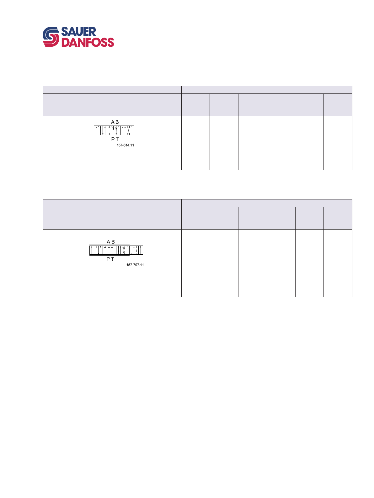
SPOOLS FOR FRICTION DETENT PVMR
Code number 161B....
Symbol
4-way, 3-position
Throttled, open neutral position
PVMR friction detent is designed for motor spools only.
SPOOLS FOR MECHANICAL FLOAT POSITION PVMF
Code number 161B....
Symbol
Pressure compensated flow l/min [US gal/min]
A
40
[10,6]
9732 9733 9734 9735 9736 9737
A
40
[10,6]
B
65
[17,2]
Pressure compensated flow l/min [US gal/min]
B
65
[17,2]
C
100
[26,4]
C
100
[26,4]
D
130
[34,4]
D
130
[34,4]
E
150
[39.6]
E
150
[39.6]
180
[47,6]
180
[47,6]
F
F
4-way, 4-position
Closed neutral position
Float P→ B → F
Spools for PVB 32, see catalog DKMH.570.C4.02. 520L0344
Spools for PVBZ 32, see Tech Note DKMH.PN.570.N2.02 520L0721
9822 9823 9824 9825 9826 9827
520L0720 • Rev. BB • Jun 2007
31
Page 32
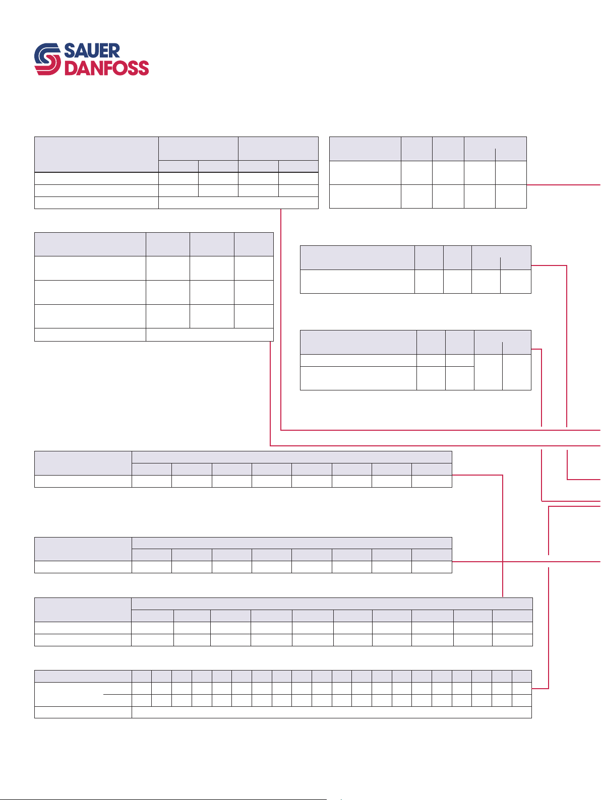
32
520L0720 • Rev. BB • Jun 2007
PVG 100 Proportional Valve
Technical Information
Module selection chart
PVB, basic module
No facilities for
Code no. 161B…
Without pilot operated check valve 6250 6650 6260 6660
With pilot operated check valve 6252 6652 6262 6662
Weight kg [lb] 5.5 kg [12.13 lb]
shock valves A and B
G 3/4 11/16 in-14 G 3/4 11/16 in-14
Facilities for
shock valves A and B
PVM, mechanical actuation
Code no. 157B....
Standard
Standard, with base, without
arm and button
Standard, without base, arm
and button
Weight kg [lb] 0.4 [0.9]
* Anodized 157B3184
With stop
screw
3171* 3191 22.5°
3172 3192 37.5°
3174 3194 37.5°
3175 3195 22.5°
3173 3193 –
Without
stop screw
PVPC (for details see catalog, 520L0344)
9
Code no. 157B… G 1/4
External pilot
supply
External pilot supply
incl. check valve
Not available for PVPV 157B5211 and 157B5611
/16 in -
18 UNF
5400 5425 0.05 0.1
5600 5625 0.05 0.1
PVTI 100/32 interface module
Code no. 161B… BSP SAE
PVTI, with T-port and PVLP
facility
T- connection G 11/4 [15/8 UN]
2200 2220 8.7 [19.18]
Tank module, PVT
Code no. 161B… BSP SAE
PVT, with T-port and PVLP facility 2500 2520
PVT, with LX connection, T-port
and PVLP facility
T- connection G 11/4 [15/8 UN]
2505 2525
Weight
kg [lb]
Weight
kg [lb]
Weight
kg [lb]
6.3 kg
[13.89]
Assembly kit PVG 100 / PVSI / PVPT
Description
Tie bolts and seals 8001 8002 8003 8004 8005 8006 8007 8008
1 PVB 2 PVB 3 PVB 4 PVB 5 PVB 6 PVB 7 PVB 8 PVB
Code number 161B….
Assembly kit PVG 100 / PVTI interface module
Description
Tie bolts and seals 8021 8022 8023 8024 8025 8026 8027 8028
1 PVB 2 PVB 3 PVB 4 PVB 5 PVB 6 PVB 7 PVB 8 PVB
Code number 161B….
Assembly kit PVB 32
Description
PVB’s 8000 8001 8002 8003 8004 8005 8006 8007 8008 8009
Weight [kg [lb] 0.1 [0.2] 0.15 [0.3] 0.25 [0.6] 0.30 [0.7] 0.40 [0.9] 0.45 [1.0] 0.50 [1.1] 0.60 [1.3] 0.65 [1.4] 0.70 [1.6]
1 PVB 2 PVB 3 PVB 4 PVB 5 PVB 6 PVB 7 PVB 8 PVB 9 PVB 10 PVB
Code number 157B....
PVLP, shock/and anti-cavitation valves
Code no. 157B… 2032 2050 2063 2080 2100 2125 2140 2150 2160 2175 2190 2210 2230 2240 2250 2265 2280 2300 2320 2350
Settings
Weight [kg [lb] 0.05 kg [0.17 lb]
bar 32 50 63 80 100 125 140 150 160 175 190 210 230 240 250 265 280 300 320 350
[psi] 460 725 914 1160 1450 1813 2031 2175 2320 2538 2755 3045 3335 3480 3625 3845 4061 4351 4641 5075
Page 33
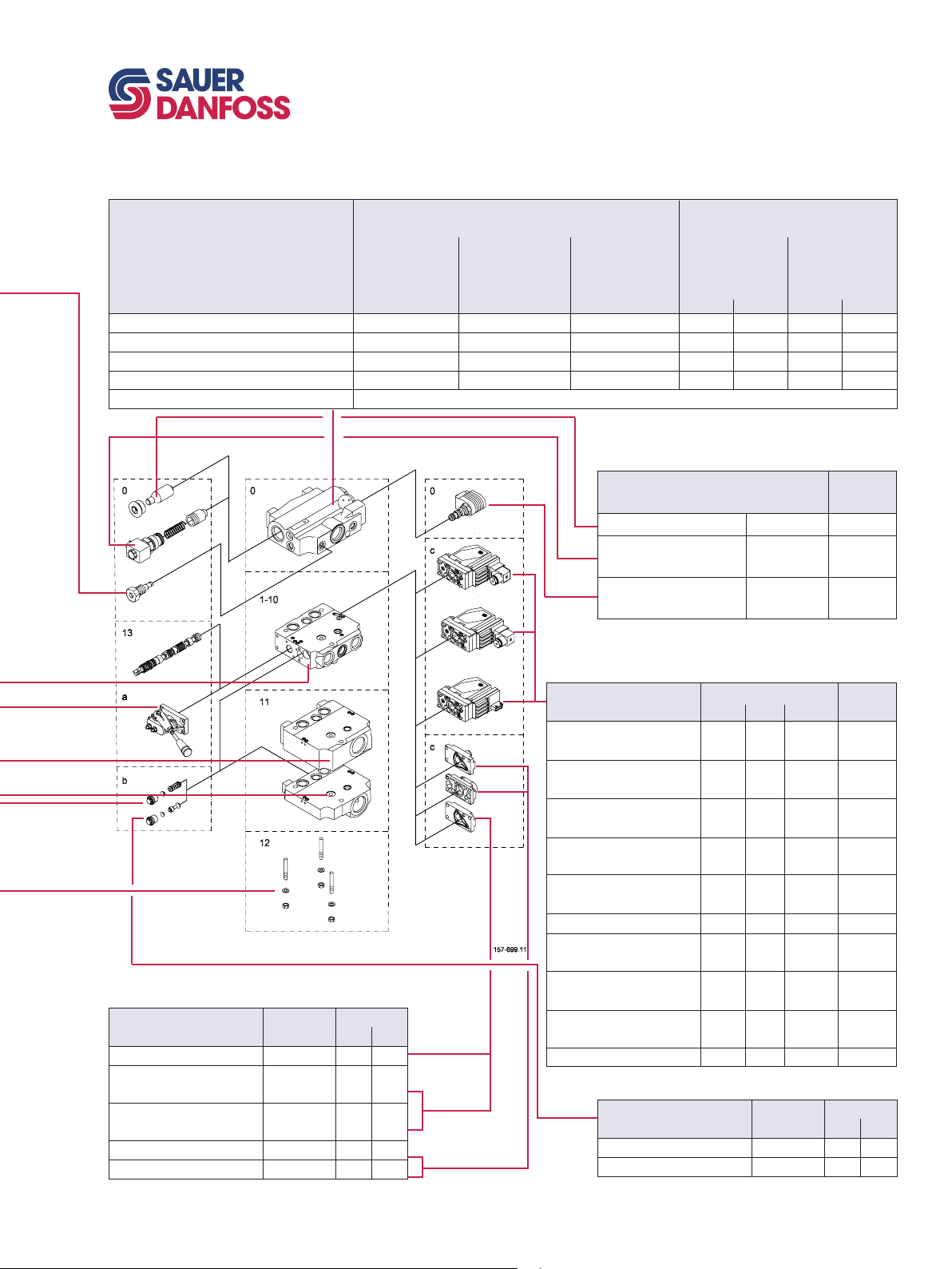
PVP 100, pump side module
Code no. 161B…
P-port = G 1
P-port = 1 5/16 UN
P-port = G 3/4
P-port = G 11/16 UN
Weight
5111 5141 - 5110 5112 5140 5142
T-port = G1 - - 5211 - - - -
T -port = 1 5/16 UN - - 5611 - - - -
kg [lb] 8.5 kg [12.30 lb]
PVG 100 Proportional Valve
Technical Information
Module selection chart
Closed center, PVPV Open center, PVPF
With pilot supply With pilot supply
for PVE for PVE
and facility for
pilot shut off
5511 5541 - 5510 5512 5540 5542
for PVE.
With integrated
priority function
for PVE
12 bar 20 bar
Accessory moduls for PVP 100
for PVE
and facility for
pilot shut off
12 bar 20 bar
PVMD, PVH, PVMR, PVMF covers
Code no. 157B… Code No.
Cover for PVM
Hydraulic actuation PVH
G 1/4
Hydraulic actuation PVH
9
/16 -18 UNF
PVMR (frict. detent) 0015 0.3 0.6
PVMF (mech. float position) 0005 0.3 0.6
0001 0.1 0.2
0008 0.2 0.4
0007 0.9 2.0
Weight
kg [lb]
Code no.
Plug, PVPD 155G5041* 0.4 [0.9]
Elec. unloading 12 V
valve, PVPE 24 V
Pilot shut off 12 V
valve, PVPP 24 V
* For PVPF only
155G5052*
155G5054*
800572719
800572819
Weight
kg lb
0.7 [1.1]
0.3 [0.7]
PVE, electrical actuation
Code no. 157B…
Hirsch AMP
PVEO, on-off
24 V 4228 4902 4292 0.6 [1.3]
PVEO-R, on/off
24 V 4229 4904 - 0.6 [1.3]
PVEA, active fault mon. - 4734 4792 0.9 [2.0]
PVEA, passive fault mon. - 4735 - 0.9 [2.0]
PVEA-DI, active fault mon. - 4736 4796 0.9 [2.0]
PVEA-DI, passive fault mon. - 4737 - 0.9 [2.0]
PVEH active fault mon. 4032 4034 4092 1.0 [2.2]
PVEH passive fault mon. 4033 4035 - 1.0 [2.2]
PVEH-F float pos. act. fault - 4338 4398 1.0 [2.2]
PVEH- DI active fault mon. - 4036 4096 1.0 [2.2]
PVEH - DI passive fault mon. - 4037 - 1.0 [2.2]
PVEP active fault mon. - - 4752 1.0 [2.2]
PVEP-F float pos. act. fault - - 4793 1.0 [2.2]
PVES, active fault mon. 4832 4834 4892 1.0 [2.2]
PVES, passive fault mon. 4833 4835 - 1.0 [2.2]
PVED-CC, Can-bus interface - 4943 4944 1.0 [2.2]
Code No. Weight
Deutsch
kg [lb]
12 V 4216 4901 4291 0.6 [1.3]
12 V 4217 4903 - 0.6 [1.3]
PVLA, anti-cavitation valve
Code no. 157B… Code No.
Plug A or B
Valve A or B 2001 0.05 0.1
2002 0.04 0.09
Weight
kg [lb]
520L0720 • Rev. BB • Jun 2007
33
Page 34

34
520L0720 • Rev. BB • Jun 2007
PVG 100 Proportional Valve
Technical Information
Order specification
ORDER SPECIFICATION An order form for Saue-Danfoss PVG 100 hydraulic valve is shown on the next page. The
form can be obtained from the Sauer-Danfoss Sales Organization.
Both the module selection chart on the previous pages and the order form are divided
into fields 0, 1-10, 11, 12, 13, a, b, and c.
Each module has its own field:
0: Pump side module PVP
Plug for external pilot oil supply PVPC
Electrical unloading valve PVPE
Electrical pilot shut off valve PVPE
1-10: Basic valves PVB
13: Main spool PVBS
a: Mechanical actuator PVM
c: Cover for mechanical actuation PVMD
Cover for hydraulic actuation PVH
Electrical actuators PVE
b: Shock and suction valve PVLP
Suction valve PVLA
11: End plate PVSI
Tank module PVT
Interface module PVTI
12: Assembly kit PVAS
Please state
- Code numbers of all modules required
- Required setting (P) for pump side module
Standard and option assembly
The PVG 100 valve group is assembled the way the module selection chart shows if the
code number for PVM is written in field a, and the code number for PVMD, PVE or PVH in
field c.
The valve group is assembled so that the mechanical actuator is mounted on the
opposite end of the basic module, if the code number for PVM is written in field c of the
order form and the code numbers for PVMD, PVE or PVH in field a.
Reordering
The space at the top right-hand corner of the form is for Sauer-Danfoss to fill in.
The code number for the whole of the specified valve group (PVG No.) is entered here.
In the event of a repeat order all you have to do is enter the number Sauer-Danfoss has
given on the initial confirmation of order.
Page 35
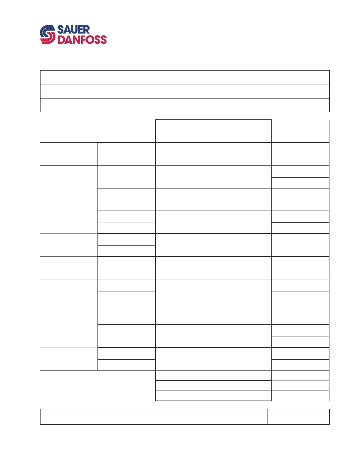
PVG 100 Proportional Valve
Technical Information
Specification sheet
Subsidiary/Dealer PVG No.
Customer Customer No.
Application Revision No.
Function A-Port
a 157B
b 157B
a 157B
b 157B
a 157B
b 157B
a 157B
b 157B
a 157B
b 157B
a 157B
b 157B
a 157B
b 157B
O 161B
p = bar
1
LSA bar LSB bar
2
LSA bar LSB bar
3
LSA bar LSB bar
4
LSA bar LSB bar
5
LSA bar LSB bar
6
LSA bar LSB bar
7
LSA bar LSB bar
__________
__________ __________
__________
___________ __________
___________ ___________
___________ ___________
___________ ___________
___________ ___________
__________
__________
__________
13
13
13
13
13
13
13
B-Port
157B c
157B b
157B c
157B b
157B c
157B b
157B c
157B b
157B c
157B b
157B c
157B b
157B c
157B b
a 157B
b 157B
a 157B
b 157B
a 157B
b 157B
Remarks 11
Filled in by Date
520L0720 • Rev. BB • Jun 2007
8
___________ ___________
LSA bar LSB bar
9
___________ ___________
LSA bar LSB bar
10
___________ ___________
LSA bar LSB bar
___________ ___________
12
___________
13
13
13
157B c
157B b
157B c
157B b
157B c
157B b
35
Page 36
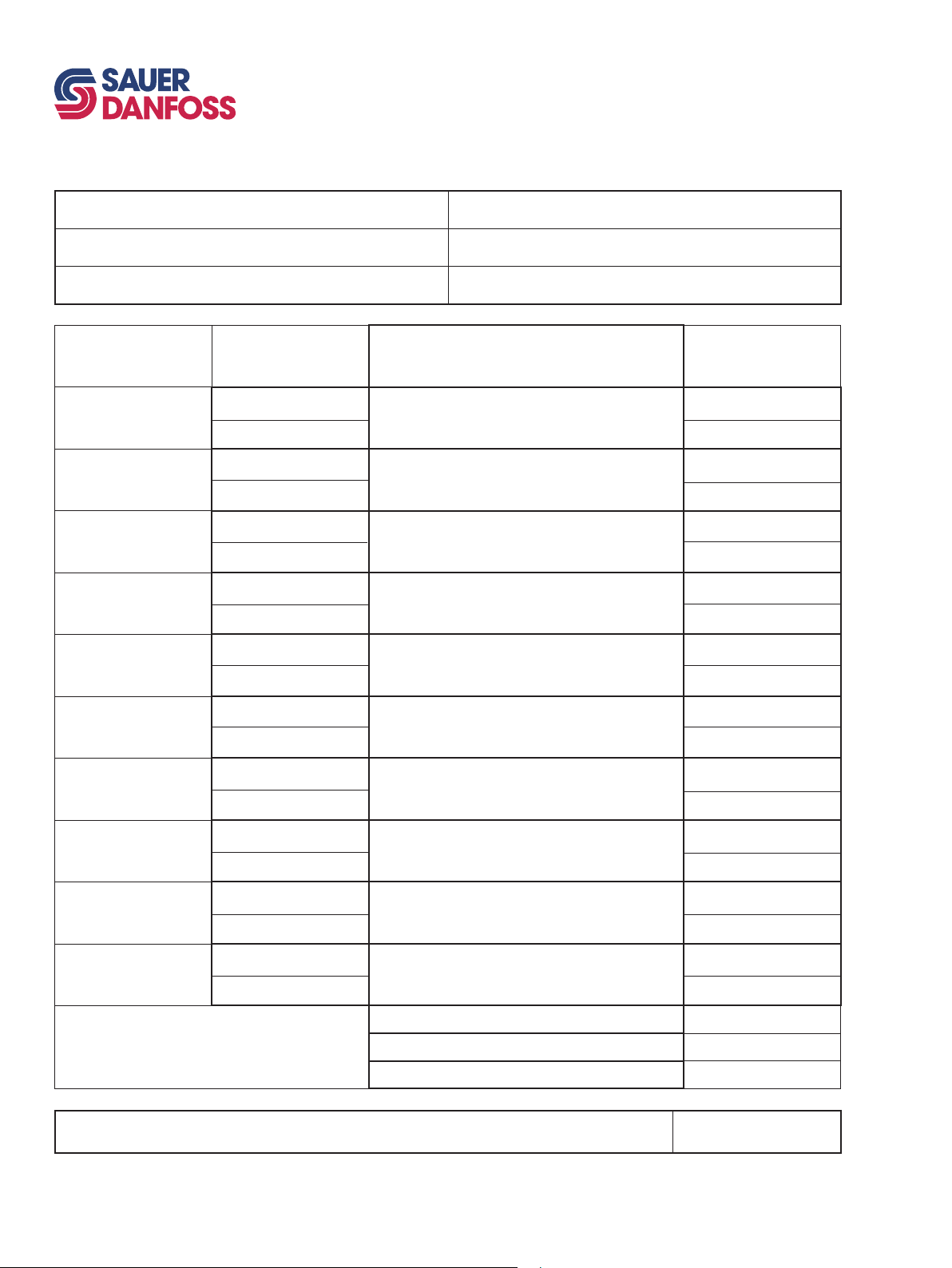
36
520L0720 • Rev. BB • Jun 2007
PVG 100 Proportional Valve
Technical Information
Specification sheet
Subsidiary/Dealer PVG No.
Customer Customer No.
Application Revision No.
Function A-Port
a 157B
b 157B
a 157B
b 157B
a 157B
b 157B
a 157B
b 157B
a 157B
b 157B
a 157B
b 157B
a 157B
b 157B
O 161B
p = psi
1
LSA psi LSB psi
2
LSA psi LSB psi
3
LSA psi LSB psi
4
LSA psi LSB v
5
LSA psi LSB psi
6
LSA psi LSB psi
7
LSA psi LSB psi
__________
__________ __________
__________
___________ __________
___________ ___________
___________ ___________
___________ ___________
___________ ___________
__________
__________
__________
13
13
13
13
13
13
13
B-Port
157B c
157B b
157B c
157B b
157B c
157B b
157B c
157B b
157B c
157B b
157B c
157B b
157B c
157B b
a 157B
b 157B
a 157B
b 157B
a 157B
b 157B
Remarks 11
Filled in by Date
8
___________ ___________
LSA psi LSB psi
9
___________ ___________
LSA psi LSB psi
10
___________ ___________
LSA psi LSB psi
___________ ___________
12
___________
13
13
13
157B c
157B b
157B c
157B b
157B c
157B b
Page 37

PVG 100 Proportional Valve
Technical Information
Notes
520L0720 • Rev. BB • Jun 2007
37
Page 38

38
520L0720 • Rev. BB • Jun 2007
PVG 100 Proportional Valve
Technical Information
Notes
Page 39

PVG 100 Proportional Valve
Technical Information
Notes
520L0720 • Rev. BB • Jun 2007
39
Page 40

OUR PRODUCTS
Hydrostatic transmissions
Hydraulic power steering
Electric power steering
Electrohydraulic power steering
Closed and open circuit axial piston
pumps and motors
Gear pumps and motors
Bent axis motors
Orbital motors
Transit mixer drives
Planetary compact gears
Sauer-Danfoss Mobile Power and Control Systems
– Market Leaders Worldwide
Sauer-Danfoss is a comprehensive supplier providing complete
systems to the global mobile market.
Sauer-Danfoss serves markets such as agriculture, construction, road
building, material handling, municipal, forestry, turf care, and many
others.
We offer our customers optimum solutions for their needs and
develop new products and systems in close cooperation and
partnership with them.
Sauer-Danfoss specializes in integrating a full range of system
components to provide vehicle designers with the most advanced
total system design.
Proportional valves
Directional spool valves
Cartridge valves
Hydraulic integrated circuits
Hydrostatic transaxles
Integrated systems
Fan drive systems
Electrohydraulics
Microcontrollers and software
Electric motors and inverters
Joysticks and control handles
Displays
Sensors
Sauer-Danfoss provides comprehensive worldwide service for its
products through an extensive network of Global Service Partners
strategically located in all parts of the world.
Local address:
Sauer-Danfoss (US) Company
2800 East 13th Street
Ames, IA 50010, USA
Phone: +1 515 239-6000
Fax: +1 515 239 6618
Sauer-Danfoss GmbH & Co. OHG
Postfach 2460, D-24531 Neumünster
Krokamp 35, D-24539 Neumünster, Germany
Phone: +49 4321 871-0
Fax: +49 4321 871 122
Sauer-Danfoss ApS
DK-6430 Nordborg, Denmark
Phone: +45 7488 4444
Fax: +45 7488 4400
Sauer-Danfoss-Daikin LTD
Sannomiya Grand Bldg. 8F
2-2-21 Isogami-dori, Chuo-ku
Kobe, Hyogo 651-0086, Japan
Phone: +81 78 231 5001
Fax: +81 78 231 5004
520L0720 • Rev. BB • Jun 2007
CENTRUM TRYK
www.sauer-danfoss.com
 Loading...