

Page 1
Gas Range Manual Page 1 Revision: 24 Feb 2011
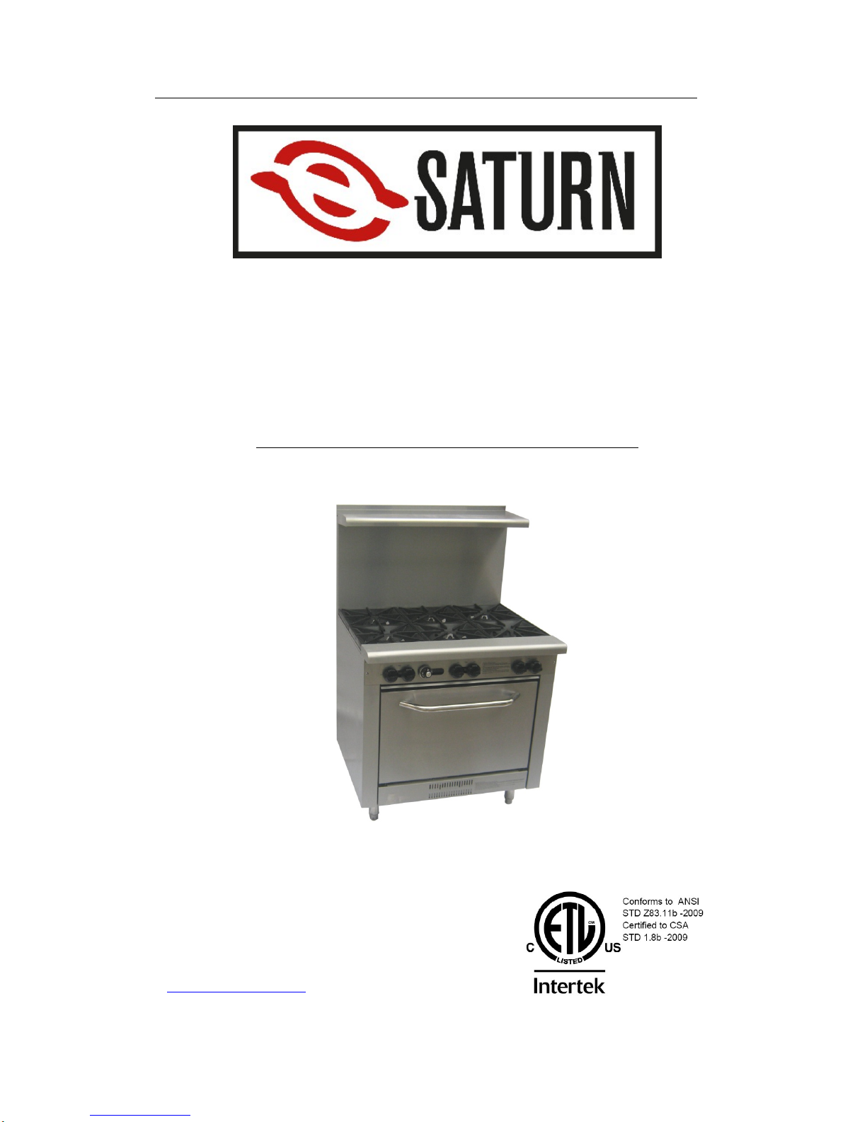
Gas range with oven
(SMDR-36-6)
Operation
Manual
Please read it carefully & keep it in a convenient place for reference
Mo
del SMDR-36-6
Saturn Equipment Primoris Inc.
5670 Greenwood Plaza,
Blvd Suite 501 Greenwood Villigae,Colorado
80111-2409
www.ThinkSaturn.com
Page 2
Gas Range Manual Page 2 Revision: 24 Feb 2011
INSTALLATION AND OPERATION
MANUAL
RANGE SERIES
WARNINGS
IMPROPER INSTALLATION, ADJUSTMENT,
ALTERATION, SERVICE OR MAINTENANCE CAN
CAUSE INJURY OR DEATH. THE INSTRUCTION
MANUAL MUST BE READ CAREFULLY BEFORE
INSTALLING, OPERATING OR SERVICING THIS
EQUIPMENT
TO BE INSTALLED ONLY BY AN AUTHORISED PERSON
IN ACCORDANCE WITH AS 5601, LOCAL AUTHORITY,
GAS, ELECTRICITY , ANY APPLICABLE ST ATUTORY
REGULA TIONS AND MANUFACTURER
REQUIREMENTS.
POST IN A PROMINENT LOCATION INSTRUCTIONS TO
BE FOLLOWED IN THE EVENT THE USER SMELLS
GAS. THIS INFORMATION SHALL BE OBTAINED BY
CONSULTING THE LOCAL GAS SUPPLIER.
FOR YOUR SAFETY
DO NOT STORE OR USE GASOLINE OR OTHER
FLAMMABLE VAPORS OR LIQUIDS IN THE VICINITY OF
THIS OR ANY OTHER APPLIANCE
Page 3
Gas Range Manual Page 3 Revision: 24 Feb 2011
THIS EQUIPMENT IS DESIGNED FOR COMMERCIAL
CATERING PURPOSES AND WILL GENERATE
SIGNIFICANT HEAT. HOT SURFACES WILL CAUSE
BURNS. A HAZARD AND RISK ASSESSMENT MUST BE
UNDERTAKEN BY OWNERS AND ALL OPERATORS
MADE AWARE OF THESE.
DO NOT STORE OR USE FLAMMABLE LIQUIDS NEAR
THIS APPLIANCE.
DO NOT SPRAY AEROSOLS NEAR THIS APPLIANCE
WHILE IT IS IN OPERATION.
INSTALLATION CLEARANCES AS SPECIFIED MUST BE
OBSERVED.
IF YOU SMELL GAS, TURN THE UNIT OFF AND THE
MAIN GAS SUPPLY VALVE TO THE UNIT. CONTACT
YOUR GAS SUPPLIER OR AN AUTHORISED PERSON.
BEFORE TURNING ON THE MAIN GAS SUPPLY, CHECK
THE UNIT TO BE CERTAIN THAT ALL THE VALVES ARE
IN THE “OFF” POSITION.
PLEASE KEEP THIS MANUAL FOR FUTURE
REFERENCE AND REFERENCE BY ALL OPERATORS.
Page 4

Gas Range Manual Page 4 Revision: 24 Feb 2011
CONGRATULATIONS
Thank you for choosing this product and welcome you to the ever-growing
customer circle. This product has been specifically designed to meet a wide
range of applications and represents the best quality and highest value
equipment.
Please read the instruction manual carefully to ensure the safe and reliable
operation and performance of your equipment.
Should you ever require service, you will be supported by trained and qualified
service network – the largest available.
We assure you of every support and wishes you every business success.
Page 5

Gas Range Manual Page 5 Revision: 24 Feb 2011
TABLE OF CONTENTS
INTRODUCTION ---------------------------------------------------------------------------------------------- 7
GENERAL ------------------------------------------------------------------------------------------------
7
WARRANTY --------------------------------------------------------------------------------------------- 7
GENERAL INFORMATION -------------------------------------------------------------------------------- 8
INSPECTION -------------------------------------------------------------------------------------------- 8
OPERATOR MANUAL --------------------------------------------------------------------------------- 8
INSTALLATION ------------------------------------------------------------------------------------------ 8
GAS CONNECTION ----------------------------------------------------------------------------------- 8
GAS PRESSURE --------------------------------------------------------------------------------------- 9
COMMISSIONING ------------------------------------------------------------------------------------- 9
SPECIFICATIONS ------------------------------------------------------------------------------------------ 10
INSTALLATION ---------------------------------------------------------------------------------------- 10
GAS INPUT INFORMATION ----------------------------------------------------------------------- 11
GAS SUPPLY PRESSURE ------------------------------------------------------------------------ 11
NOMINAL GAS CONSUMPTION ---------------------------------------------------------------- 11
TEST POINT PRESSURE-------------------------------------------------------------------------- 12
VENTILATION & AIR SUPPLY -------------------------------------------------------------------- 12
OPERATING INSTRUCTIONS ------------------------------------------------------------------------- 13
LIGHTING INSTRUCTIONS ----------------------------------------------------------------------- 13
OPEN TOP BURNERS ------------------------------------------------------------------------------ 14
OVEN BURNER -------------------------------------------------------------------------------------- 14
OPERATOR MAINTENANCE --------------------------------------------------------------------------- 15
SEASONING THE GRILL -------------------------------------------------------------------------- 15
CLEANING STAINLESS STEEL ------------------------------------------------------------------ 16
OVEN INTERIOR (Enamel) ------------------------------------------------------------------------ 16
OPEN TOP BURNERS ------------------------------------------------------------------------------ 16
TRIVETS ------------------------------------------------------------------------------------------------ 17
Page 6

Gas Range Manual Page 6 Revision: 24 Feb 2011
TABLE OF CONTENTS (continued)
SERVICE ........................................................................................................................ 18
RECOMMENDED SERVICE ................................................................................... 18
SERVICE INFORMA T ION ....................................................................................... 18
OPEN AND GRILL BURNER ADJUSTMENTS ........................................................ 19
OVEN CONTROL SETTINGS AND ADJUSTMENTS .............................................. 20
CONVERSION INSTRUCTIONS ............................................................................. 21
SPARE PARTS ........................................................................................................ 22
TROUBLE SHOOTING ................................................................................................... 23
ALL BURNERS ........................................................................................................ 23
OVEN ....................................................................................................................... 24
RANGE – EXPLODED VIEWS,PART LIST AND GAS DIAGRAM ........................... 25-32
RANGE – INSTALLATION OF BACKGUARD .......................................................... 33-35
NOTES ............................................................................................................................ 36
Page 7

Gas Range Manual Page 7 Revision: 24 Feb 2011
INTRODUCTION
GENERAL
The range is designed for commercial catering purposes and incorporates a
wide range of design features..
WARRANTY
This product is subject to the correct installation, operation, maintenance and
care of the equipment.
Warranty does not extend to:
• Damages caused in shipment
• Damage as a result of incorrect installation.
• Damage as a result of incorrect operation
• Damages caused by unauthorised service and use of non original parts
• Gas supply issues to the equipment
• Failure resulting from improper maintenance.
• Failure as a result of tampering with, removal of, or changing any preset
control or safety device
• Service ‘After hours’
• Conditions as defined in dealer’s terms and condition of sale
Please ensure you quote the Model and Serial Number of the unit.
Page 8

Gas Range Manual Page 8 Revision: 24 Feb 2011
GENERAL INFORMATION
Inspection.
Please inspect the unit on receipt. If the unit is damaged, contact the carrier
immediately and file a damage claim with them. Save all packing materials
when filing a claim. Freight damage claims are the responsibility of the
purchaser and are not covered under warranty.
Operator Manual.
This manual contains important information for your safety and the
installation, operation, maintenance and service of this equipment.
Please read the manual carefully and ensure all operators of the
equipment are aware of the contents and safety requirements. You must
also assess all hazards and risks associated with the operation of the
equipment in your environment and advise all operators of these.
Installation.
This equipment must be installed by an authorized person in accordance
with local codes, or in the absence of local codes, with the national fuel
gas code (ANSI Z223.1), or the natural gas installation code CAN/CGA
B149.1, or the propane installation code CAN/CGA B149.2, as well as
local gas, electricity, any applicable statutory regulations and
manufacturer requirements.
An approved gas shut-off valve must be installed between the main gas piping
system and the appliance. To facilitate servicing of appliance, it is advisable
to install a 3/4” pipe union between gas shut-off valve and equipment.
Gas Connection.
The appliance must be connected by an authorized person to the gas type
specified on the unit. The gas type is shown adjacent to the rear gas
connection point and on the data plate. Connect to and use only the correct
type of gas.
Page 9

Gas Range Manual Page 9 Revision: 24 Feb 2011
Gas Pressure.
The authorized person installing this equipment must ensure that the gas
operating pressure is the same as shown on the rating plate and that there is
sufficient gas volume.
The unit and its individual shut off valve must be disconnected from the gas
supply piping system during any pressure testing of the gas supply piping
system at test pressures in excess of 1/2 PSIG (3.45 kPa)
Commissioning.
The authorized person installing this equipment must commission the
equipment - gas leakage, operational checking, adjustments and instructing
the owner on use of the equipment are prescribed requirements.
The equipment must be isolated from the gas supply piping system by closing
its individual manual shut off valve during any pressure testing of the gas
supply piping system at test pressures equal to or less than 1/2 PSIG (3.45
kPa)
Page 10

Gas Range Manual Page 10 Revision: 24 Feb 2011
SPECIFICATIONS
INSTALLATION
THIS EQUIPMENT MUST BE INSTALLED BY AN
AUTHORIZED PERSON IN ACCORDANCE WITH LOCAL GAS
SAFETY CODE, LOCAL AUTHORITY, GAS, ELECTRICITY,
ANY APPLICABLE STATUTORY REGULATIONS AND
MANUFACTURER REQUIREMENTS.
NOTE: INSTALLATION IS THE RESPONSIBILITY OF THE OWNER
Gas Inlet Connection: 3/4” NPT Female.
Gas Connection Point: For Range units, the gas connection point is
located at the rear of the unit 810 mm (32”) above
the floor and 45 mm (1.8”) from the right hand side
Gas Connection: Prescribed requirements include, commission the
equipment, gas leakage testing, operational
checking and adjustments.
All units are tested and adjusted at the factory; however, burners and pilots
must be checked at the installed location and adjusted if necessary.
Model
Top
Burners Qty
Oven
Qty
Product
breadth
(inch/mm)
Product
depth
(inch/mm)
Product
height
(Inch/mm)
SMDR-36-6 6 1 36 / 916 33 / 840 59 / 1495
Page 11

Gas Range Manual Page 11 Revision: 24 Feb 2011
Installation Clearances: The MINIMUM clearance from combustible and
noncombustible surfaces is 9” (229 mm) from the
sides and 6” (152 mm) from the rear. Adequate
clearance must also be provided for service.
Levelling: Refer also to ‘Clearances Oven Base’ above.
To adjust the legs to level the unit to the floor
and/or to slightly adjust the height of the unit, raise
the front of the unit and adjust the legs (ensure
safe work practices). Similarly, raise the back and
adjust the legs. DO NOT LAY THE UNIT ON ITS
BACK. ENSURE THE UNIT IS LEVEL.
GAS INPUT INFORMATION
GAS SUPPLY PRESSURE
Gas Type Operating Gas Pressure
Natural Gas 5” (1.25 kPa)
LP Gas 10”( 2.49 kPa)
To verify gas pressure, use the special plug on the gas line or the pilot burner
line. The burner(s) should be working at maximum capacity during the
pressure verification.
Pressure verification: Turn on all other gas equipment in the kitchen as well.
Check gas pressure on dial of pressure gauge with all equipment on “HI”, then
turn all other equipment off except range and check again.
NOMINAL GAS CONSUMPTION
NA
TURAL GAS PROPANE GAS
BURNER
(EACH)
ORIFICE
(mm)
Btu/h GAS
PRESSURE
ORIFICE
(mm)
Btu/h GAS
PRESSURE
OPEN (Each) 2.5 32000 5” 1.70 27000 10”
OVEN (Each) 2.5 32000 5” 1.70 27000 10”
Note: Pressure test point is located at the gas manifold of the top section
Page 12

Gas Range Manual Page 12 Revision: 24 Feb 2011
TEST POINT PRESSURE
The pressure test point is located on the gas manifold. The gas manifold and
pressure test point is accessed by removing the gas valve control knobs and
the front panel. The test point pressure is shown in the Nominal Gas
Consumption Table.
VENTILA TION AND AIR SUPPL Y
All gas burners and pilots require sufficient air to operate. For optimum
performance and for your safety, it is ESSENTIAL that the equipment, in the
installed position, has the proper air and ventilation and the correct
exhaust/canopy and air balance. The correct installation and compliance with
all regulatory and other requirements is the responsibility of the
purchaser/owner.
Please note that a strong exhaust canopy will create a vacuum if there is
insufficient replacement air. The amount of air exhausted must be replaced by
an equal amount of air.
Airflow to the appliance must not be blocked or restricted (e.g. large objects
should not be placed in front of the appliance). The flue must never be covered
or restricted in any way.
Page 13

Gas Range Manual Page 13 Revision: 24 Feb 2011
OPERATING INSTRUCTIONS
LIGHTING INSTRUCTIONS
DO NOT OPERATE THE UNIT UNLESS IT HAS BEEN
INST ALLED AND COMMISSIONED BY AN AUTHORIZED
PERSON.
BEFORE TURNING ON THE MAIN GAS SUPPLY, CHECK AND
ENSURE THAT ALL THE VALVES ARE IN THE “OFF”
POSITION.
THIS EQUIPMENT IS DESIGNED FOR COMMERCIAL
CATERING PURPOSES AND WILL GENERATE SIGNIFICANT
HEA T. HOT SURF ACES WILL CAUSE BURNS. A HAZARD AND
RISK ASSESSMENT MUST BE UNDERTAKEN BY OWNERS
AND ALL OPERATORS MADE AWARE OF THESE.
NOTE: Ensure the gas supply to the equipment is turned ON.
WARNING: When open top burners adjacent to the backguard or the side
of a grill plate are operated at high heat and covered by large
cooking vessels (i.e. pots, pans etc), dispersing heat may
cause discolouration and or distortion of the adjacent metal
surface.
Page 14

Gas Range Manual Page 14 Revision: 24 Feb 2011
OPEN TOP BURNERS
1. Before attempting to light the appliance, the cover, if so equipped, shall be
opened.
2. Make sure all valves are closed before turning on the gas supply.
3. Turn on the pilot valve with a screw driver. Light up the pilot with a flame
gun.
4. When the pilot is lit, turn on the main valve by rotating it anticlockwise 90o
to the position “ON”. The main burner will then be lit up. To turn off the
valve, rotate it clockwise to “OFF”. A 5 minute complete shutoff period
should be allowed before the appliance is relighted.
5. To turn off all open burners and pilot:
Turn off the main valves. When all burners go out, turn off the pilot valves
with a screw driver.
OVEN BURNER
WARNING: ENSURE THE PILOT IS ESTABLISHED BEFORE
TURNING ON THE THERMOSTAT. THE PILOT FLAME CAN BE SEEN
THROUGH THE VIEWING HOLE.
1. Before attempting to light the appliance, the cover, if so equipped, shall be
opened.
2. Make sure the thermostat located on the control panel is turned off.
3. Take off the lower panel, press the black button of the safety valve for 15 to
30 seconds. Stick the flame gun through an opening to light up the pilot
(located at about 100 mm behind the opening). Wait for 5 to 10 seconds
before releasing your finger on the black button. Repeat the above
process again if the pilot flame does not stay by now.
4. When the pilot flame is lit, turn the thermostat to the desired temperature
(250 – 500oF). You can observe the flame of the oven burner from an
opening behind the lower panel. You may replace the lower panel now.
5. To turn off the oven, rotate the thermostat clockwise to “OFF” position.
The oven burner should go out immediately. A 5 minute complete shutoff
period should be allowed before the appliance is relighted.
Adjustment of main burners
Proper flame setting of main burners is obtained by loosening set screw on air
shutters and to proceed as follows:
Air shutters should first be opened all the way for a sharp blue flame, then
slowly close until the flames turns soft with just a minimum of yellow at the tips.
Page 15

Gas Range Manual Page 15 Revision: 24 Feb 2011
OPERATOR MAINTENANCE
CONTACT THE FACTORY, THE FACTORY REPRESENTATIVE
OR A LOCAL SERVICE COMPANY TO PERFORM
MAINTENANCE AND REPAIRS.
USE ONLY SUITABLE CHEMICALS AND OBSERVE ALL
MANUFACTURER SAFETY REQUIREMENTS FOR SAFE
HANDLING AND USE.
SEASONING THE GRILL (only applicable if there is a grill)
NOTE: The grill surface has protective coating applied at manufacture.
Remove this by washing with hot water and a mild detergent until clean.
Season the grill by applying a thin coat of cooking oil with a cloth to the entire
grill surface. Remove any excess oil with a cloth.
Light the grill burner(s) and set at the lowest level. Operate the grill for about
20 minutes and then wipe away the oil. Repeat this procedure three times.
IMPORTANT: Only use low heat when seasoning the grill.
NOTE: The grill surface will discolour from heat. Discolouring will not affect the
grill surface function and does not render the grill surface defective.
The grill surface should be cleaned with hot water and detergent.
Normally, if maintained properly, the grill will not need to be seasoned again. If
however, the grill has been overheated and product sticks to the grill surface, it
may be necessary to season the grill again.
Carbon and grease will affect the cooking performance and should be
removed as follows:
After each use, clean the grill thoroughly with a sharp grill scraper and wipe
off any excess debris.
Page 16

Gas Range Manual Page 16 Revision: 24 Feb 2011
NOTE: Empty the grease drawer as necessary and clean.
Weekly, clean the grill surface thoroughly with a grill pad while the surface is
still warm (not hot). After cleaning, ensure any detergent/chemical is
thoroughly removed. The grill surface should be covered with a thin film of
cooking oil to prevent rusting.
Note: The grill plate is made of steel and can be easily scored or dented by
careless use of scrapers and spatulas.
CLEANING STAINLESS STEEL
Regularly wipe the surface with hot water and detergent. Rinse the washed
area with a wet sponge and clean water and wipe the area dry to prevent
streaking. Follow this process and wash a small area at a time to prevent
chemical residue and streaking.
Stainless steel may discolour if overheated. These stains can usually be
removed using an appropriate powder/paste. To scrape off heavy deposits of
grease and oil, use only wood or plastic tools as necessary.
Note: Never use steel wool to clean stainless steel.
Note: Damage may occur if chemicals not suitable for stainless steel are used.
OVEN INTERIOR (Enamel)
Note: Remove all oven racks and guides and clean these separately with a
suitable detergent and warm water.
The enamelled oven interior surface should be cleaned regularly with a
suitable oven cleaner.
OPEN TOP BURNERS
Note: Spillage is the major cause of problems to the performance of open top
and pilot burners. Spillage can block gas ports, which then causes burners to
operate inefficiently or, in bad cases, not at all. Clean any spillages as they
occur.
To clean the burners, remove the burner cap and clean with a suitable
detergent and warm water. If the burner ports are blocked, clean these with a
stiff brush. Place the burner cap back on the burner, ignite and check that the
flame is even and comes from all ports (this dries the burner cap).
Page 17

Gas Range Manual Page 17 Revision: 24 Feb 2011
If any ports remain clogged, remove the burner cap and complete burner and
clean thoroughly with a suitable detergent and hot water. Dry thoroughly,
ensure the air shutter is fully open, reinstall (ensure the injector is located in
the burner venturi), ignite and check the flame pattern.
Note: The burner flame should be uniformly blue. If yellow flames are present,
this may indicate that grease and dirt are present in the burner throat. Remove
and clean the burner per the above.
TRIVETS
The trivets should be removed from the appliance before cleaning.
To clean the trivets, wash with warm water and a suitable detergent using a
soft cloth and then dry.
For heavily soiled trivets, use a suitable oven cleaner and non-abrasive pad or
brush.
Page 18

Gas Range Manual Page 18 Revision: 24 Feb 2011
SERVICE
CONTACT THE FACTORY, THE FACTORY REPRESENTATIVE
OR A LOCAL SERVICE COMPANY TO PERFORM
MAINTENANCE AND REPAIRS.
FOR YOUR SAFETY, ALL SERVICE WORK MUST BE
CARRIED OUT BY AN AUTHORISED PERSON AND USE
ONLY ORIGINAL SUPPLIED AND SPECIFIED PARTS.
TEST ALL FITTINGS, PIPES AND PIPE CONNECTIONS FOR
LEAKS IN ACCORDANCE WITH APPROVED GAS LEAK
TEST PROCESSES AND METHODS. DO NOT USE A
FLAME.
Note: When checking gas pressure, ensure that all other equipment on
the same line is turned “ON”.
RECOMMENDED SERVICE
It is recommended that your appliance be serviced by an authorized person. It
is for guidance purpose only and may vary based on usage of the equipment
and operator care. Prescribed service tasks include;
• Functional test of all components and clean and adjust as necessary.
• Inspect and clean all gas valves and lubricate with an industry approved
lubricant.
• Inspect all gas piping.
• Check and adjust specified gas pressures.
• Leak test.
• Full operational, performance and safety test.
SERVICE INFORMAT ION
To access gas valves, remove control knobs and the front panel.
To remove a gas valve, disconnect the gas valve from the manifold connection
and remove the valve.
To access oven burner thermocouples/pilots, remove oven base.
Page 19

Gas Range Manual Page 19 Revision: 24 Feb 2011
OPEN AND GRILL BURNER ADJUSTMENTS
Leak Test
Ensure that all valves are in the OFF position.
Turn on the main gas supply valve.
Light all pilots.
Leak test all valves and fittings using approved methods.
Correct any leaks as required and re-check.
Shut off all valves and set thermostat dials to “OFF” position.
Test Point Pressure
The open top and grill gas pressure test point is located on the gas manifold.
The gas manifold and pressure test point is accessed by removing the gas
valve control knobs and the front panel. The test point pressure is shown in the
Nominal Gas Consumption Table and is set with two open top burners
operating at maximum setting.
Burner Adjustment
The open top, grill and oven burner orifices are fixed as specified and cannot
be adjusted. The specified gas rate will be achieved if the gas supply
pressure and test point pressure is correct.
A distinct blue flame over the entire port area of the burner will be achieved at
full rate when the air supply is correct and the air shutter is properly adjusted.
If the flame is yellow and wavy, the cause needs to be established.
Page 20

Gas Range Manual Page 20 Revision: 24 Feb 2011
OVEN CONTROL SETTINGS AND ADJUSTMENTS
Test Point Pressure
The oven burner pressure test point is located also on the manifold test point
on the top section. The test point pressure is shown in the Nominal Gas
Consumption Table
Page 21

Gas Range Manual Page 21 Revision: 24 Feb 2011
CONVERSION INSTRUCTIONS
TO BE COMPLETED BY AN AUTHORISED PERSON
ENSURE GAS IS ISOLATED WHILE PERFORMING
CONVERSION WORK. PERFORM A LEAK TEST BEFORE
IGNITING AND CALIBRATING BURNER AND PILOT
ADJUSTMENTS.
TO PROPANE GAS
Regulator Change regulator to PROPANE gas configuration
and adjust as necessary
Open Burner/Grill Burner Access and change the injectors to PROPANE Gas
injectors (refer Nominal Gas Consumption
Table)
Oven Burner Access and change the injector to a PROPANE
Gas Injector (refer Nominal Gas Consumption
Table)
LEAK TEST IN ACCORDANCE WITH APPROVED METHODS
Ignite burners and adjust.
AMEND DATA PLATE AND APPLY ‘PROPANE’ GAS LABEL
TO NATURAL GAS (NG)
Regulator Change regulator to NG gas configuration and
adjust as necessary
Open Burner/Grill Burner Access and change t he injectors to a NG Injectors
(refer Nominal Gas Consumption Table)
Oven Burner Access and change the injector to a NG Injector
(refer Nominal Gas Consumption Table)
Page 22

Gas Range Manual Page 22 Revision: 24 Feb 2011
LEAK TEST IN ACCORDANCE WITH APPROVED METHODS
Ignite burners and adjust
AMEND DATA PLATE AND APPLY ‘NATURAL GAS’ LABEL
SPARE PARTS
A list of major spare part items is shown at the end of this manual.
Page 23

Gas Range Manual Page 23 Revision: 24 Feb 2011
TROUBLE SHOOTING
ALL SERVICE WORK TO BE COMPLETED BY AN
AUTHORISED PERSON.
ALL BURNERS
CONDITION CHECK
Pilot will not light. Gas supply is on and gas pressure is correct
Blocked pilots
Pilot adjusting screw
Pilot repeatedly goes out. Pilot flame size and position
Yellow Burner Flame. Primary air and adjust air shutter
Flame lifting off burner ports. Primary air
Air shutter
‘Popping’ after turning off. Primary air
Air shutter
Burner flame too large. Gas pressure
Delayed ignition. Pilot flame
Burner and ports clean
Air shutter
Gas pressure
Flame burns back to orifice Primary air
Air shutter
Page 24

Gas Range Manual Page 24 Revision: 24 Feb 2011
OVEN
Incorrect oven temperature Oven thermostat and control dial position
Burner shuts off at set Thermostat/by-pass
temperature
Page 25

Gas Range Manual Page 25 Revision: 24 Feb 2011
Exploded view (SMDR-36-6)
Page 26

Gas Range Manual
Page 26
Revision: 24 Feb 2011
Gas diagram(SMDR-36-6)
Page 27

Gas Range Manual
Page 27
Revision: 24 Feb 2011
Installation of backguard
Page 28

Gas Range Manual
Page 28
Revision: 24 Feb 2011
Page 29

Gas Range Manual
Page 29
Revision: 24 Feb 2011
 Loading...