


Contents
CONTENTS
Chapter 1 Introduction………………………………………………………1-5
Chapter 2 Safty ………………………………………………………………2-1
Chapter 3 Equipment Description and Component Identification…3-1
Chapter 4 Installation ………………………………………………………4-1
Chapter 5 Ink Jet Printer Operation ………………………………………5-1
Chapter 6 Maintenance ……………………………………………………6-1
Chapter 7 Troubleshooting …………………………………………………7-1
Appendix:
1. Hydraulic System Connecting Figure …………………………8-1
2. Electric System ……………………………………………………8-2
3. Hydraulic System …………………………………………………8-3
4. Printing Speed List ………………………………………………8-4
5. User-defined Font…………………………………………………8-5
6. S400 Series Upgrade Introduction……………………………8-11
Version: 20100420
Introduction
1
In this chapter you will find:
Introduction
z a brief description of the intended use of the machine
z who this manual is intended for, how it is organized, and the
writing conventions that are used to present information
z an introduction to each of the chapters in this manual
WARNING: Read chapter 2, Safety, before attempting to
service operate the equipment.
Turn to page 1-2 for a chapter-level Table of Contents.
1-1

Introduction
Chapter 1 Contents
Introduction - - - - - - - - - - - - - - - - - - - - - - - - - - 1-3
References to the S400 serials printer - - - - - - - 1-3
Printers Supplies - - - - - - - - - - - - - - - - - - - - - -1-3
Who Should Use this Manual? - - - - - - - - - - - - - - - - - 1-4
Writing Conventions Used In this Manual - - - - - - - - - - - - 1-5
1-2

Introduction
Introduction
The S400 Serials Printer is a non-contact ink jet printer designed to print small character messages
onto a product. This equipment is typically used for industrial marking, coding and overprinting. The
technical specialties are listed as followed.
For ease of reading, the S400 Series Printer will be referred to as
References to the
S300/400 Printer
Due to the large variety of SATURN Inks available for use with this
Printer Supplies
the “S480 Printer” or “Printer” throughout the remainder of this
Manual.
product, this printer can print on virtually any surface, texture,
contour or shape.
Contact your SATURN sales representative or distributor if you
have any question regarding supplies selection (inks, make-up
fluids and cleaning solutions) or product application.
1-3

Introduction
Who Should Use this Manual?
Introduction
This Manual is intended for use by SATURN service personnel
and those customers who are qualified to perform their own
printer service and maintenance.
WARNING: Customers who intended to service and maintain the
printer themselves must be qualified personnel,
which are considered those persons who have the
proper technical training (successful completion of a
training course covering this printer), have
experience to work on this equipment, and are aware
of the hazards to which they will be exposed. The
Service Manual is intended to be supplement (and
not a replacement) to training.
The Manual contains information on operating, installing, setting
up, maintaining, troubleshooting, and servicing the printer.
Keep this Manual in a safe location where it can be easily
accessed for reference.
1-4

Introduction
Service Manual Overview
Chapter 2, Safety
This chapter contains important equipment and safety guidelines, as well as the safety writing
conventions used throughout the manual.
Chapter 3, Equipment Description and Component Identification
This chapter shows the location and provides a brief description of each of the main
components in the printhead, the hydraulic and electronic co mpartments of the printer.
Chapter 4, Installation
This chapter includes the necessary procedures when installing the printer and setup the
technical data.
Chapter 5, Printer Operation
This chapter includes an overview of the fluid system, a description of how ink drops are
created and controlled, and detailed functional sequences of operation for electrical, and
hydraulic functions.
Chapter 6, Maintenance
The maintenance chapter lists all recommended scheduled maintenance procedures, ink
maintenance procedures, and procedures to follow to attain th e finest print quality.
Chapter 7. Troubleshooting
This chapter includes the cause, judge, and solutions of printer common fault s.
1-5
Safety
2
Safety
In this chapter you will find:
important safety guidelines to follow when operating the
equipment
important safety guidelines to follow when working with
inks, make-up fluids, and cleaning solutions
important safety guidelines to follow when long-term
shutdown
printhead cleaning
shutdown without cleaning
recovery tube cleaning
WARNING: Read this chapter thoroughly before attempting
Refer to page 2-2 for a chapter-level Table of Contents.
to operate this product.
2-1

Safety
Chapter 2 Contents
Introduction - - - - - - - - - - - - - - - - - - - - - - - - - -2-3
Safety Terms - - - - - - - - - - - - - - - - - - - - - - - - - - - 2-4
Fire Prevention Statements- - - - - - - - - - - - - - - - -2-4
Danger Statements - - - - - - - - - - - - - - - - - - - -2-4
Warning Statements - - - - - - - - - - - - - - - - - - - 2-4
Caution Statements - - - - - - - - - - - - - - - - - - - 2-4
Equipment Safety Guidelines - - - - - - - - - - - - - - - - - - 2-5
Comply with Electrical Codes - - - - - - - - - - - - - - - 2-5
Avoid Breathing Exhaust Vapors - - - - - - - - - - - - - 2-5
Do Not Remove Warning Labels - - - - - - - - - - - - - 2-5
Ink Safety Guidelines - - - - - - - - - - - - - - - - - - - - - 2-6
No Smoking - - - - - - - - - - - - - - - - - - - - - - - 2-6
Wear Safety Glasses - - - - - - - - - - - - - - - - - - -2-6
Avoid Skin Contact - - - - - - - - - - - - - - - - - - - 2-6
Dispose of Ink Properly - - - - - - - - - - - - - - - - - 2-6
Store Inks Properly - - - - - - - - - - - - - - - - - - - -2-6
Ground the Service Tray - - - - - - - - - - - - - - - - - 2-6
Ink and make-up fluid caution items- - - - - - - - - - - - - - - - - - - - 2-7
Long-term Shutdown- - - - - - - - - - - - - - - - - - - - - - - - - - - - 2-8
Printhead Cleaning- - - - - - - - - - - - - - - - - - - - - - - - - - - - - -2-8
Shutdown without Auto Flush - - - - - - - - - - - - - - - - - - - - - 2-9
Recovery Tube Cleaning - - - - - - - - - - - - - - - - - - - - - - - - -2-10
2-2

Safety
Introduction
z The policy of Saturn Technologies Ltd. is to manufacture non-contact printing/coding systems
and ink supplies which meet high standards of performance and reliability. We enforce strict
quality control techniques to eliminate the potential defects and haza rds in our products.
z The intended use of the S480 printer is to print information directly onto a product. Use of this
equipment in any other fashion may lead to serious personal injury.
z The safety guidelines provided in this chapter are intended to educate the operator on all safety
issues in order to operate the printer in a safe manner.
z The safety guidelines provided in this chapter are intended to educate the operator on all safety
issues in order to install, service, and maintain the printer in a safe manner.
z Before using this printer, thoroughly read this chapter and follow the guidelines strictly.
z You must use Saturn’s ink、make-up, or the warranty period will stop automatically.
z Please find technical support from distributor directly. Do not use untrained staff in the warranty
period, or the warranty period will stop automatically.
z Filter and O ring are consumables, which are not included in warranty, please replace on time.
2-3
Safety
Safety Conventions Used in this Manual
Fire prevention statement The ink and make-up fluid are both flammable and may cause fire.
Danger Statements Danger statements:
Please keep any fire five meters away from the printer, and set up
the printer in dry environment
are used to indicate immediate hazards which WILL result in
severe personal injury or death
have a triangular symbol with an
immediate left
are always found before the step or piece of information to
Warning Statements Warning statements:
are used to indicate hazards or unsafe practices which could
have a triangular symbol with an exclamation point to the
are always found before the step or piece of information to
Caution Statements Caution statements:
are used to indicate hazards or unsafe practices which could
is preceded by the word "DANGER"
which they refer
result in severe personal injury or death
immediate left
is preceded by the word “WARNING”
which they refer
result in minor personal injury or product or
property damage
exclamation point to the
have a triangular symbol with an
immediate left
is always preceded by the word CAUTION
2-4
exclamation point to the
Safety
Equipment Safety Guidelines
WARNING: Always observe the following safety guidelines when
Comply with Electrical Codes
Shutdown the power before opening printer door;
Do not insert tweezers, screw driver or any steel material into ink
ejection hole at the end of printhead. When the printer is ready to
print, a high voltage (approximately 6 kV) is applied to the
deflection electrode section in the printhead.
Exercise caution to avoid electric shock, injury, and fire.
Avoid Breathing Exhaust Vapors
During operation, the printer exhausts vapors through the muffler.
These vapors may be flammable and present a healthy hazard. For
these reasons, do not allow the exhaust to be confined to an area
that does not have proper ventilation or near a source of ignition.
Printer exhaust fumes are generally heavier than air, so keep all
sources of ignition away from low areas where fumes may travel or
accumulate. Ensure that no welding operations are performed
within 5 m of the printer.
Do Not Remove Warning Labels
Do not, under any circumstances, remove or obstruct any warning
or instruction labels in the printer.
WARNING: Do not place the printer in an explosive atmosphere.
If emergency occurs, press the power switch to turn off the power.
Use the printer at the temperature with 0—40°C and relative
humidity of 30-90%, or will cause fault to printer.
Do not mix different types of ink together, or will cause printer fault
Printer should link to ground well, or will affect printing.
installing, operating, servicing, or maintaining the
printer and associated equipment.
2-5
Safety
Ink Safety Guidelines
WARNING: Always observe the following safety guidelines when
No Smoking
Do not smoke when near the printer or printhead. Explosion or fire
Ground the Service Tray Ground the Saturn service tray to the printer, and install the
may result if the printer exhaust fumes are subjected to an ignition
source.
Wear Safety Glasses
Wear safety glasses with side shields (or equivalent eye protection)
when handling any ink, make-up fluid or cleaning solution. If
splashed into your eyes, flush eyes with water for 15 minutes and
see a doctor immediately.
Avoid Skin Contact
Wear butyl rubber gloves when handling any ink, make-up fluid or
cleaning solution. Avoid contact with skin and mucous membranes
(nasal passage, throat). Upon contact with skin, remove any
contaminated clothing and wash area with soap and water. See a
doctor if irritation persists.
Dispose of Ink Properly
Do not pour any ink, make-up fluid, or cleaning solution into sinks,
sewers, or drains. Waste disposal must comply with local
regulations; contact the appropriate regulatory agency for further
information.
Store Consumables Properly
The ink and make-up fluid are both flammable and may cause fire,
and must be stored properly. Consult the appropriate regulatory
agency for further information
printhead into the service tray when test printing or dumping ink
from the printhead. This is necessary to avoid the possibility of
electrostatic discharge which may result in fire.
working with any ink, make-up fluid, or cleaning
solution.
2-6
Safety
Ink and Make-up Fluid Caution Items
1. Ink and make-up replenishment
While the printer is operated, the ink and make-up are automatically transferred at fixed intervals
from the ink or make-up tank to the main ink supply pipe for replenishment purposes. If the ink or
make-up sufficiency alarm is issued, add ink or make-up to the tank within 60 minutes. If such
replenishment procedure is not completed within 60 minutes, the printer comes to a stop.
2. Ink replacement
Refer to “System Maintainence ”.
During printer operated, ink will polluted by dust. Long-term running will cause to badly charge
of ink. Replace the ink refer to the table as below;
Replacement periods Type Numbers
Operating hours Period
Normal black ink R1182 800-1200 hours 8 month
Low viscosity ink R1180 800-1200 hours 8 month
Invisible blue ink R1360 600-1000 hours 6 month
Alcohol endurable ink R1582 600-1200 hours 8 month
High adhesive ink R1782 600-1200 hours 6 month
White pigment ink R1000 600-1000 hours 6 month
Edible ink R1960 300-600 hours 3 month
3. Store requirement
1) The ink and make-up must be hermetically sealed and stored in a cool dark place(0 to 20 ℃)
2) Using the ink and make-up before “Unseal period”.
3) Once the ink unsealed, please use it as soon as possible, if the ink in the printer over the
time which in above table, that means the ink can not be used any more.
4) Once the make-up unsealed, please add into the ink jet printer within one year. Do not need
to change the make-up.
Caution
: Waste ink and make-up can not be poured into sewer or public places.
2-7
Safety
Long-term Shutdown Guidelines
Please refer to the procedure of "auto flush" in the system maintenance. Long-term shutdown
requires that you drain out the ink from the printer and flush the ink system. This is necessary, as left
ink in the system will dry/solidify, causing problems when re-commissioning the printer.
Cleaning of Print Head
Most of ink used in printer is fast dry ink. This type of ink will come to dry and solidify immediately.
The "auto flush" function ensures that the nozzle and gutter will be cleaned when the printer is
starting up and shutting down.
Some ink sprayed out of the nozzle over time will accumulate on the charge deflection plate/nozzle
plate, causing the ink stream unable to spray out. It is necessary to clean the printhead manually.
(1) Take off nozzle cover, spray out make-up on nozzle plate, charge deflection, H.V. deflection
electrode and gutter, clean out printhead.
Screw for Printhead Cover
Do not clean this area with
cleanings.
Use wet paper with cleanings
to clean this area.
Charge Electrode
Cleaning
Range
(2) Clean out the nozzle as the picture shows. Can not spray out make-up to other area.
(3) Dry the printhead using the rubber pipette bulb.
z Ensure the nozzle, charge electrode, H.V. deflection electrode, gutter and surrounding area
are clean enough.
z Do not force make-up to flow inside the nozzle.
Nozzle
Nozzle Plate
H.V. Deflection Electrode
Gutter
2-8
Safety
Shutdown without Auto Flush
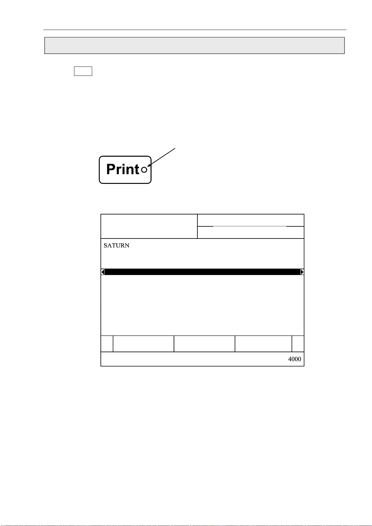
Press the
this shutdown frequently in a short period of time will cause surplus adding of make-up to the
system. If the shutdown time is less than 30 seconds, you should perform the quick shutdown
procedure.
Quick shutdown: If the shutdown time is less than 30 seconds you may perform the quick
Print Status
Print Key for 2 seconds, the printer will start to shutdown with a "system cleaning”. Using
shutdown procedure to avoid surplus adding of make-up. This procedure will
shorten shutdown time. Shutdown without auto flush is used normally for
maintenance purposes only.
(Green LED)
z Press “Print Key”, green LED will off, and status area will indicate “Printer is
ready”;
System St atus:
Printer is ready
System Maintainence-1
2007/12/26 12:00
Ink On/Off Print Test
H.V. On/Off
Current Flow Time:
z Enter “System Maintainence-1”, select “Ink On/Off”, status area will display
“Printer is Shutting down H.V.”, “Printer is Shutting down”. When the ink in
recovery tube is drain out, you can turn off the switch to maintain the printer.
Caution
① After finishing maintenance on the printer using "shutdown without auto flush"
it is important to note that if you intend not to use the printer for some time you
must perform the normal shutdown procedure to make sure that the ink recovery
tube is perfectly clean.
② After finish the maintenance, if need to start up again, manually cleaning the
nozzle procedure is needed to perform to make sure the ink stream perfectly
recover to the gutter.
:
2-9


Safety
Recovery Tube Cleaning
If the printer is running for a long time without auto flush, the recovery tube may accumulate some
ink and will need to be cleaned.
Caution
: Do not perform recovery tube cleaning more than twice.
2-10

Equipment Description and Component Identification
3
Equipment Description and
Component Identification
In this chapter you will find:
a brief description of the two main printer assemblies --- the
control unit and the printhead
the location and a brief description of the function of the main
components in the hydraulic, and electronic compartments of
the printer, as well as the printhead
Turn to page 3-2 for a chapter-level Table of Contents.
3-1

Equipment Description and Component Identification
Chapter 3 Contents
Equipment Description- - - - - - - - - - - - - - - - - - - - - - - - - - - - - - - 3-3
Introduction - - - - - - - - - - - - - - - - - - - - - - - - - - 3-3
Control Unit- - - - - - - - - - - - - - - - - - - - - - - - - - 3-4
Hydraulic Compartments - - - - - - - - - - - - - - - - - - - - - 3-4
Electronic Compartments- - - - - - - - - - - - - - - - - - - - - 3-5
Keyboard - - - - - - - - - - - - - - - - - - - - - - - - - - - - - - - - - 3-5
The Printhead- - - - - - - - - - - - - - - - - - - - - - - - - 3-6
Component Identification - - - - - - - - - - - - - - - - - - - - 3-7
Introduction- - - - - - - - - - - - - - - - - - - - - - - - - 3-7
The Location and Description of a Main Component- - - - 3-7
Hydraulic Components - - - - - - - - - - - - - - - - 3-7
Electronic Components - - - - - - - - - - - - - - - 3-14
Printhead Components - - - - - - - - - - - - - - - 3-16
3-2
Equipment Description and Component Identification
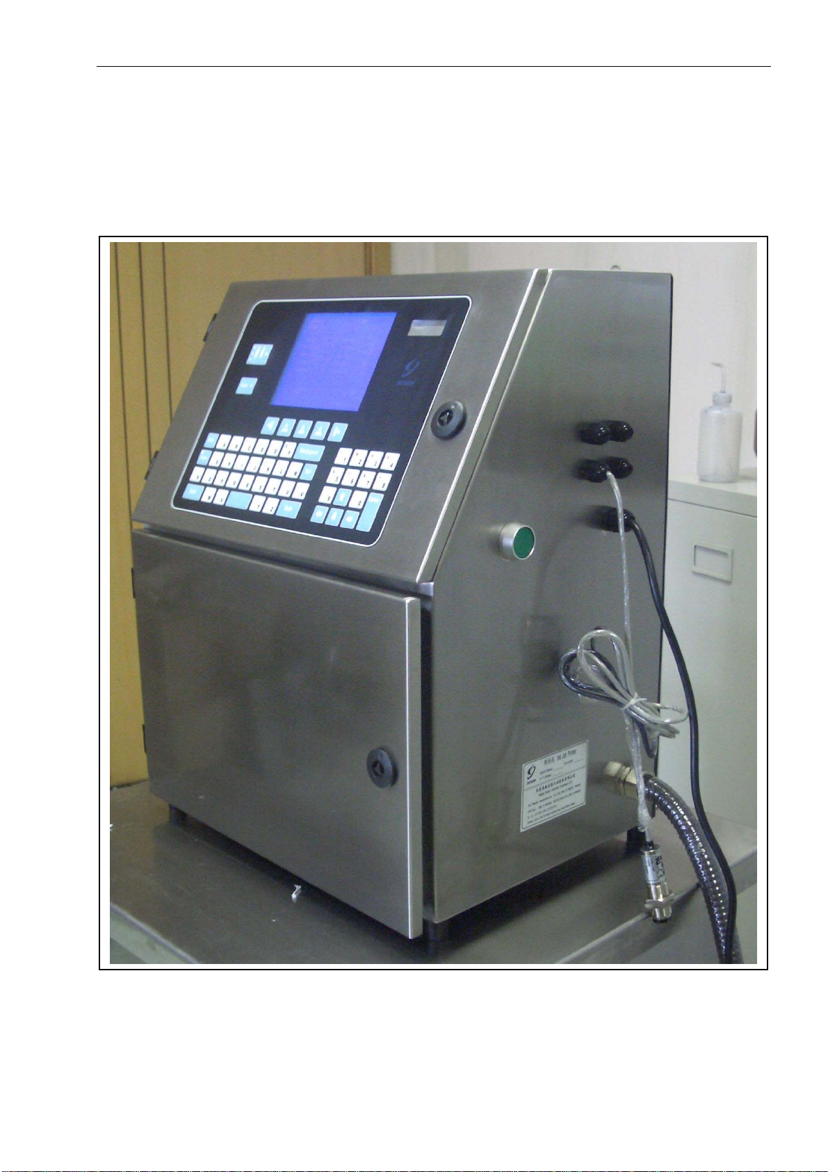
Introduction The S400 Series printer is comprised of two basic assemblies
-- the control unit and the printhead -- connected by an umbilical
assembly (a flexible conduit containing electrical and fluid lines).
Refer to Figure 3-1.
Figure 3-1. S400 Series Printer
3-3
Equipment Description and Component Identification
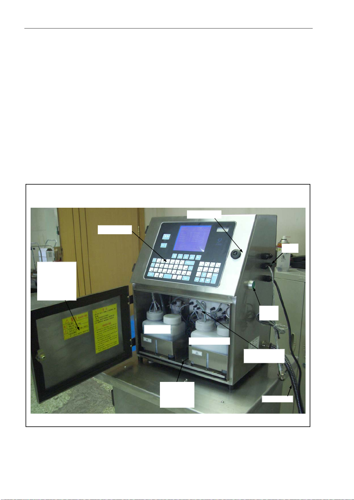
Control Unit
Hydraulics Compartment
(Fluid pan)
For more information
The control unit consists of the hydraulic and electronic
compartments of the printer, as well as the keyboard
(Refer to Figure 3-2).
The hydraulics compartment is located behind the front
door of the control unit (refer to Figure 3-2). This is where
ink and makeup fluid are stored, monitored, and
maintained to ensure proper fluid viscosity. This is also
where pressure is applied to the ink to ensure proper
velocity of the ink drops at the printhead.
Caution
commonly referred to as the “fluid pan”.
Refer to Hydraulic Components on page 3-7 for
information on the main components found in the
hydraulics compartment.
Keyboard
Lower Door
(Open before
maintaining or
filling ink and
makeup in)
Ink Tank
Figure 3-2. The Control Unit
: The hydraulics compartment is also
Upper Door
Makeup Tank
Support Tray
(loosen the
screw to pull
out the tray)
Power
Supply
Hydraulics
Compartment
Umbilicals
Ports
3-4
Equipment Description and Component Identification
n
Electronic Compartments
For more inf ormatio
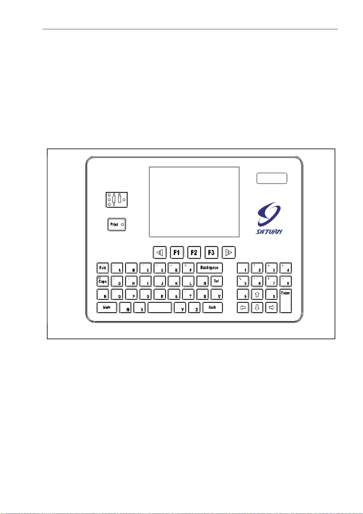
Keyboard
Figure 3-3. Keyboard
Electronic compartments are set in the upper door (refer to
Figure 3-2). The main function is to control all the electronic
signal.
Refer to Electronic Components on page 3-16 for
information on the main components found in the
electronic compartment.
The keyboard is located on the front of the control unit (refer
to Figure 3-2). The keyboard consists of control keys, an alpha
keypad, and a display screen (refer to Figure 3-3). Use the
keyboard to operate the printer.
3-5
Equipment Description and Component Identification
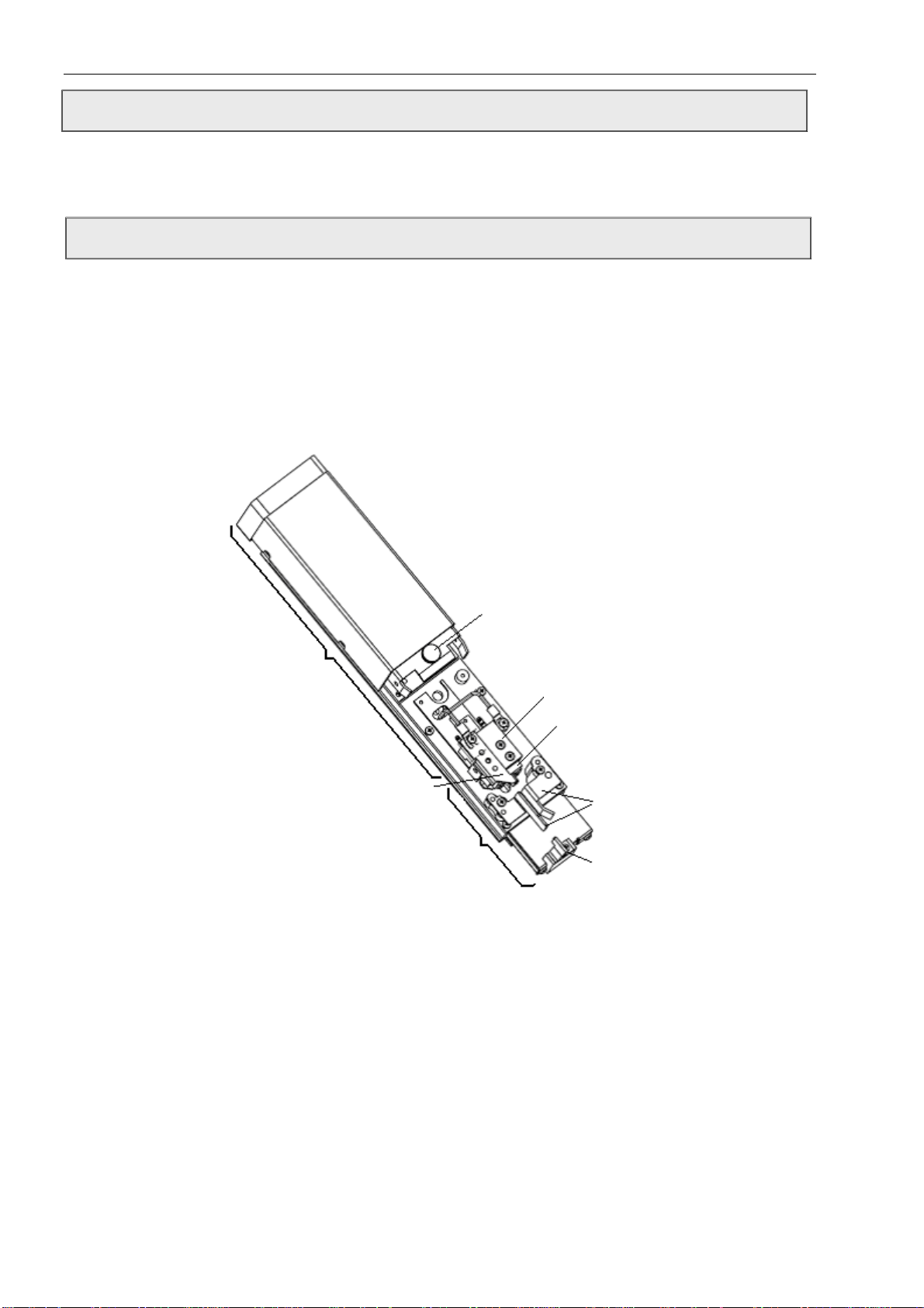
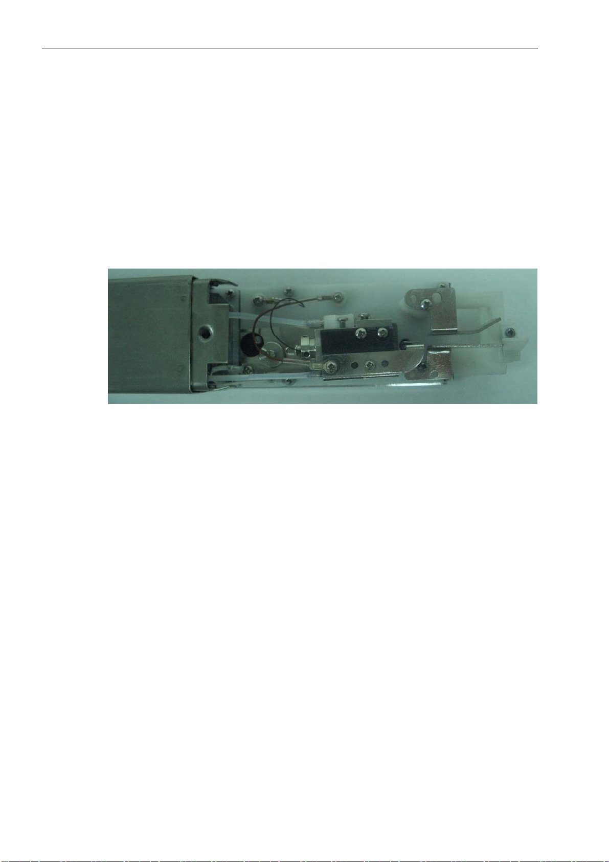
The Printhead The printhead is connected to the control unit by the umbilical
assembly. The printhead receives pressurized ink through the
umbilical, and turns the ink stream into tiny electrically
charged ink droplets which are deflected onto a substrate to
form a printed code.
For more information
Refer to Printhead Components on page 3-15 for information
on the main components found in the printhead.
Refer to Chapter 5, Inkjet Printer Operation,for more
information on how the printhead works.
Figure 3-4. Printhead
3-6

Equipment Description and Component Identification
Component Identification
Introduction This section identifies the location and describes the function
of the main components included in the hydraulic, pneumatic,
and electronic compartments of the control unit, as well as the
main components in the printhead.
Only main printer components are covered in this section.
This section is divided into the following subsections:
Hydraulic Components - - - - - - - - turn to page 3-7
Electronic Components - - - - - - - turn to page 3-13
Printhead Components - - - - - - -- turn to page 3-15
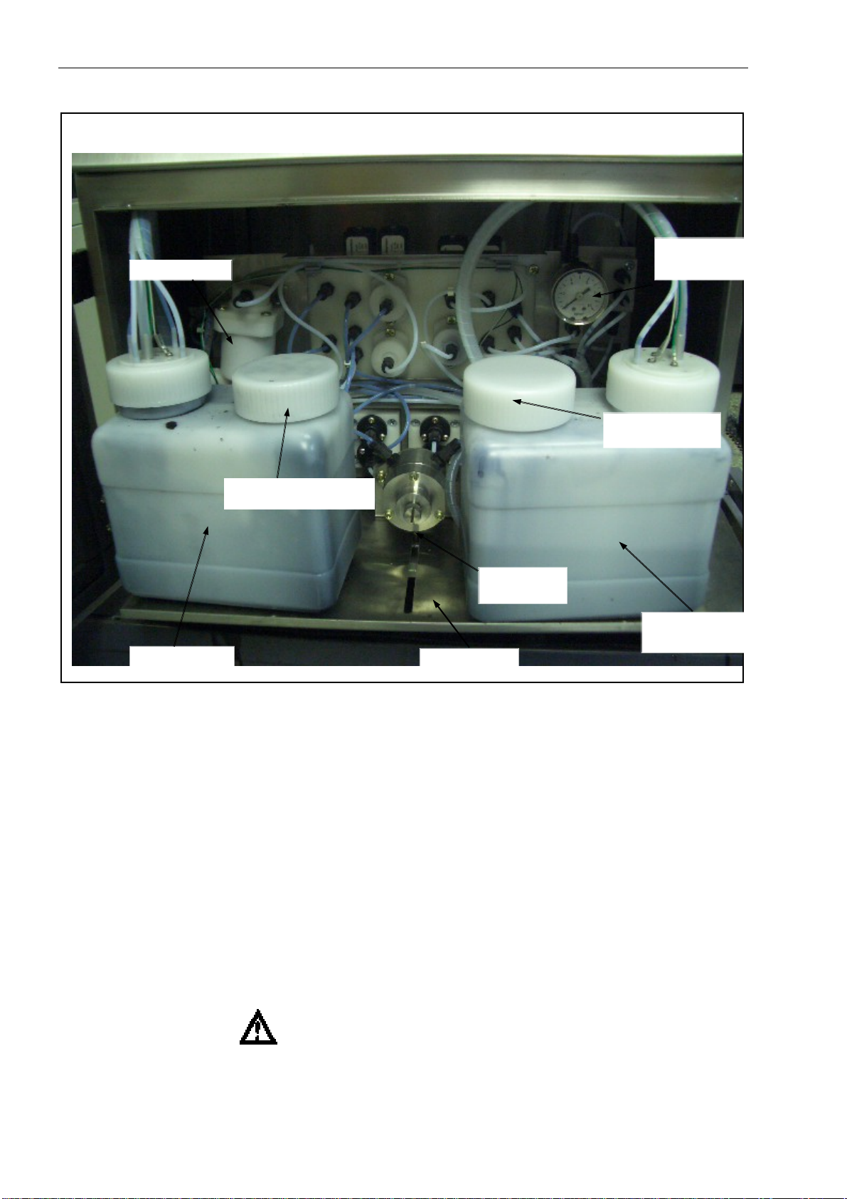
Hydraulic Components Refer to Figure 3-5 and Figure 3-6 for the location of the main
hydraulic components, and refer to the following pages to find
a brief description of the function of the components.
Caution
components.
: Open the lower door to check the hydraulic
3-7
Equipment Description and Component Identification
Viscosimeter
Ink Pouring Orifice
Ink Pressure
Regulator
Ink Tank
Support Tray
Figure 3-5. Hydraulics Compartment-1 (with support tray pulled out)
1. Ink Pressure Gauge
The ink pressure gauge indicates the amount of air pressure (in
psi and bar) applied to the ink supply cylinder. This pressure is
commonly referred to as "ink pressure”. The ink pressure is
controlled by adjusting the ink pressure regulator (refer to page
3-10).
2. Ink Pressure Regulator
The ink pressure regulator is used to adjust the ink pressure, and
accordingly to change the speed of the ink steam. According to
the style of ink and the measure of print head, ink pressure is
usually set at 2.8- 3.5 bar(40- 50 psi).
WARNING: Do not adjust the ink pressure regulator unless
you are performing the “Viscosity Calibrate”
procedure. (Refer to page 6-26)
3-8
Ink Pressure
Gauge
Makeup Pouring
Orifice
Makeup Tank

Equipment Description and Component Identification
3. Ink Tank
The ink tank stores fresh ink for printer.
4. Makeup Tank
The Makeup tank stores Makeup and adds Makeup to the ink when
ink becomes too dense.
5. Support Tray
The support tray carries the whole hydraulic system, ink and
Makeup tank, which can be pulled out in order to check the
hydraulic system.
Note: Please loose the support tray lock before pulling out the
tray.
6. Viscosimeter
The viscosimeter includes a metal float and a sensor to monitor
the viscosity coefficient of the ink.
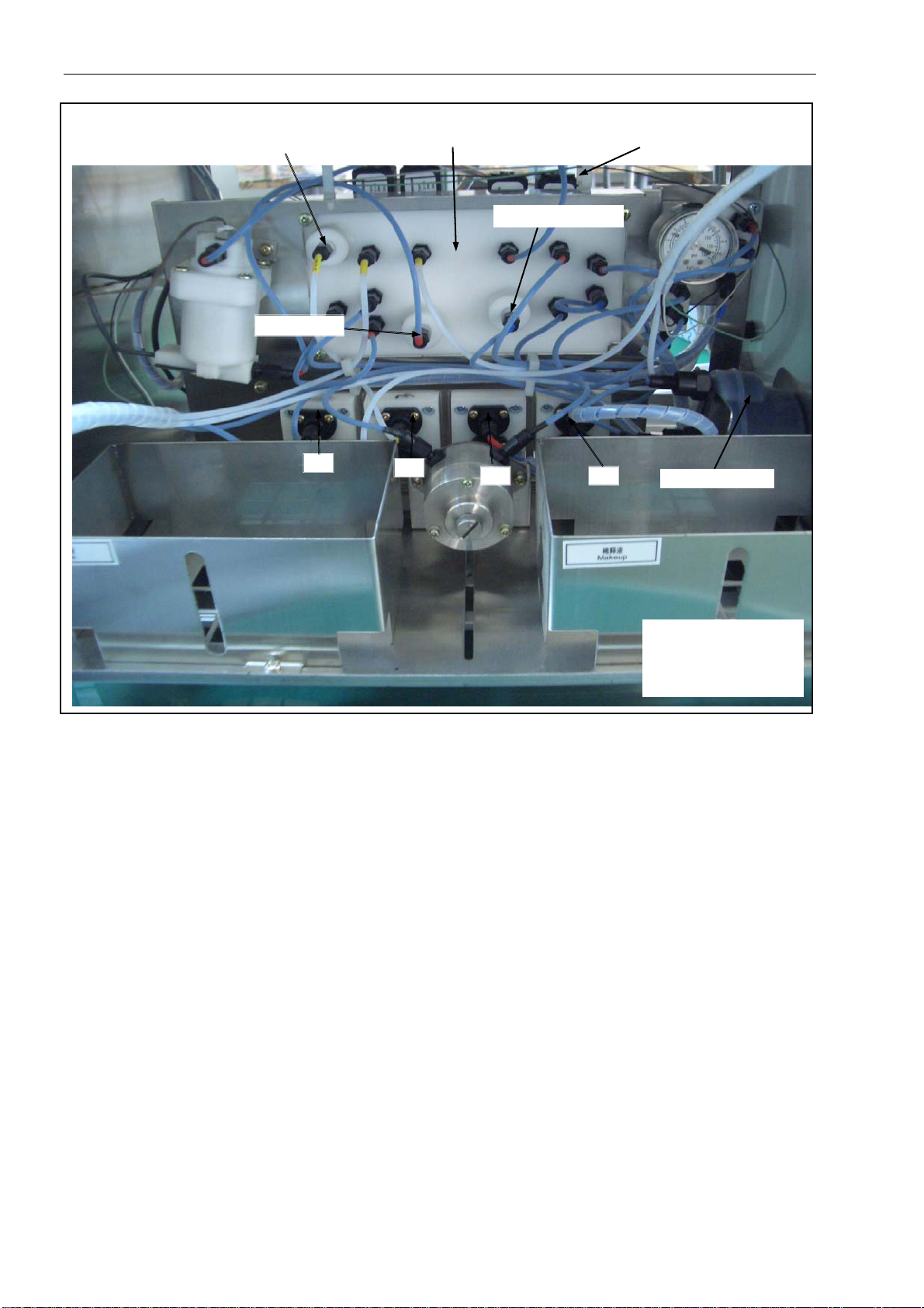
7. Main Ink Filter
The main ink filter is installed at the right side of the bracket
(Figure 3-6). It filtrates and cushions the ink going to hydraulic
system.
8. Makeup Filter
The Makeup filter filtrates the Makeup ink going to flush pipe in
the printhead (Figure 3-6), and prevents dust into printhead.
9. Churn Filter
The churn filter filtrates the ink going to the viscosimeter (Figure
3-6), and prevents dust into viscosimeter.
10. Recovery Filter
The recovery filter filtrates un-used ink from gutter (Figure 3-6),
and prevents dust into ink tank.
3-9
Equipment Description and Component Identification
Makeup
Filter
Valves Board
Churn Filter
11
12
Figure 3-6. Hydraulics Compartment-2
11. Ink Supply Pump
The ink supply pump transfers ink to printhead and generates a
pressure to spurt out the ink through printhead.
12. Makeup Pump
The makeup pump transfers the makeup ink to the printhead and
generates a pressure to spurt out the Makeup ink to clean the
printhead.
13. Circulation Pump
The circulation pump absorbs ink from viscosimeter and also
absorbs ink from printhead and returns ink to ink tank.
14. Recovery Pump
The recovery pump returns un-used ink from printhead to ink
tank.
Recovery Filter
1413
Solenoid Electric Valves
Main Ink Filter
11 Ink Supply Pump
12 Makeup Pump
13 Circulation Pump
14 Recovery Pump
3-10
Equipment Description and Component Identification
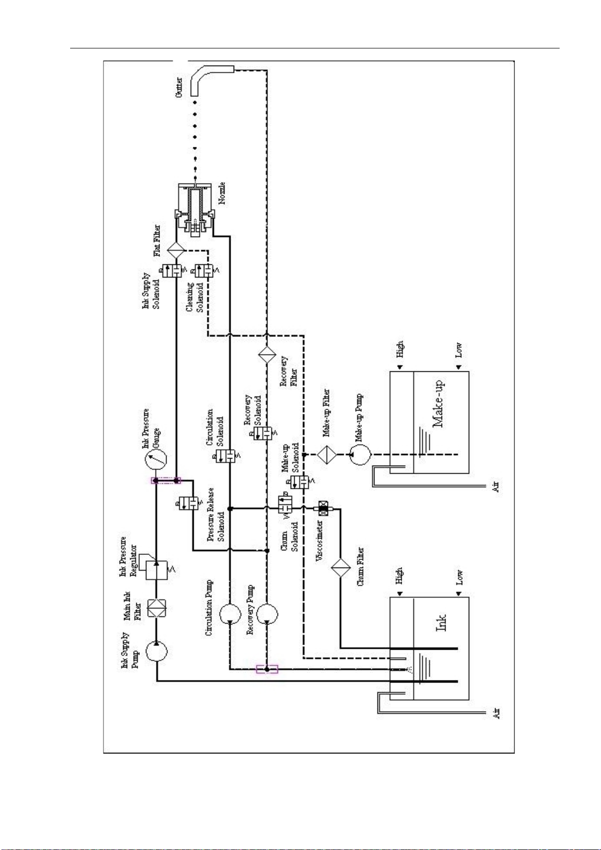
Figure 3-7 Hydraulic System
3-11
Equipment Description and Component Identification
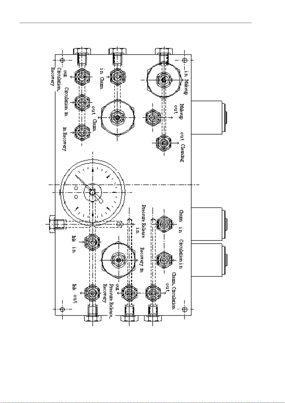
Figure 3-8 Perspective Drawing for Valves Board
3-12

Equipment Description and Component Identification
15. Electric Solenoid Valve Assembly
The Electric Solenoid valve assembly distributes positive pressure
and vacuum to each connector and Electric Solenoid valve.
(Figure 3-8)
16. Ink Supply Electric Solenoid Valve
Turn on the ink supply Electric Solenoid valve and then the ink in
the ink supply pump and the main ink filter is able to reach ink
pressure gauge and printhead. (Figure 3-7 & 3-8)
17. Makeup Ink Electric Solenoid V alve
The Makeup ink Electric Solenoid valve controls flush pump to
add Makeup ink from Makeup ink tank when the viscosity
coefficient is above the initialization to adjust the viscosity to a
normal level. (Figure 3-7 & 3-8)
18. Cleaning Electric Solenoid V alve
Turn on the cleaning Electric Solenoid valve and then makeup ink
in the makeup pump will reach the printhead and complete clean
automatically. (Figure 3-7 & 3-8)
19. Churn Electric Solenoid V alve
After turning on the churn Electric Solenoid valve, the circulation
pump will absorb the ink in the ink tank to the viscosimeter, and
then from viscosimeter back to the ink tank to complete churning
the ink. (Figure 3-7 & 3-8)
20. Circulation Electric Solenoid Valve
Turn on the circulation Electric Solenoid valve, and then recycle
pump will absorb the ink in ink supply pipe back to ink tank to
complete the air release of ink supply pipe. (Figure 3-7 & 3-8)
21. Pressure Release Electric Solenoid Valve
After turning on the pressure release Electric Solenoid valve,
recycle pump will absorb the ink in the ink supply pump and main
ink filter back to ink tank to complete ink pressure release and
shut the ink stream quickly. (Figure 3-7 & 3-8)
22. Recovery Electric Solenoid Valve
Turn on the Recovery Electric Solenoid valve and then recovery
pump returns the un-used ink from printhead to the ink tank.
(Figure 3-7 & 3-8)
3-13

Equipment Description and Component Identification
Electronic Components Refer to Figure 3-10 for the location of the main electronic
components, and refer to the following pages to find a brief
description of the function of the components.
Caution
: To access this compartment, use the keys and/or
the hex key (supplied with the printer) to open the cabinet door.
27 Reverse Side
of Upper Door
23 Ink Control Unit
25 Print Drive Unit
24 Print Control Unit
23 Ink Control Unit(ICU)
24 Print Control Unit(PCU)
25 Print Drive Unit(PDU)
26 Input/Output Unit(IOU)
26 Input/Output Uint
28 Main Power
29 High Voltage
Power
Figure 3-10. Electronic Compartment
3-14

Equipment Description and Component Identification
23. Ink Control Unit(ICU)
ICU receives data from edit control unit and completes the control
of ink circulation, ink level and viscosity inspection.
24. Print Control Unit(PCU)
PCU receives data from edit control unit to control print signal
(step wave, sine wave, high voltage, etc.) and return data to edit
control unit.
25. Print Drive Unit(PDU)
PCU receives data from print control unit and output step wave,
sine wave, high voltage to the print head to realize printing.
26. Input/Output Unit(IOU)
IOU provides various connectors to synchronizer, magic eye and
U disc to enhance the reliability.
27. Edit Control Unit(ECU)
ECU realizes the communication between printer and human;
completes edit, store and download of message, setting of data
and control of printing.
28. Main Power
The main power supply transfers 110/220vac to low voltage direct
current power for PCB control and dual high voltage power.
29. High Voltage Power
The high voltage power supplies 900V to 6000V high voltage
power for printing.
3-15

Equipment Description and Component Identification
r
Printhead Components Refer to Figure 3-11 for the location of the main printhead components,
and refer to the following pages to find a brief description of the function
of the components.
45
42
41
48
46
43
40
49
40. Charging Electrode
41. Ground Electrode
42. Solenoid Cover
43. Nozzle
44. Gutte
45. High Voltage Deflection Electrode
46. Horizontal Locking Screw
47. Vertical Adjustment Screw
48. Horizontal Adjustment Screw
49. Recovery Tube (printhead)
Figure 3-11. Printhead Components
40. Charging Electrode
The charging electrode is an electrode that charges the ink drops
as they leave the nozzle.
41. Ground Electrode
Positioned directly opposite the high voltage deflection electrode,
the ground electrode acts as the lower electrode (where, the high
voltage deflection electrode is the upper electrode). Refer to High
voltage deflection electrode in 3-17 for further information.
3-16

Equipment Description and Component Identification
42. Solenoid (Ink Supply, Cleaning Solenoid)
Attached to the rear of the nozzle,the solenoid controls the flow of
pressurized ink to the nozzle. The Solenoid opens at40psi (2.8 bar)
of ink pressure.
43. Nozzle
The nozzle is an assembly which houses a jeweled orifice and a
piezo-electric crystal used to change the ink stream into ink
droplets. The nozzle is electrically-driven by an oscillator on the
print control board to produce ultrasonic vibrations that break the
ink stream into droplets.
44. Gutter
The gutter collects the ink drops that are not used for printing.
Vacuum draws all unused ink droplets back into the ink tank for
recirculation. The recovery block also contains a sensing
electrode used to detect charged ink drops to monitor the drop
chargeability when not printing.
45. High Voltage Deflection Electrode
Positioned directly opposite the ground electrode, the high
voltage deflection electrode provides the positive high voltage
(upper electrode). The ink drops pass through the electric field
created between the high voltage deflection electr ode and the
ground electrode. The high voltage deflection electrode causes
the negatively charged drops to be de flected over the gutter to
produce a printed code.
46. Horizontal Locking Screw
The horizontal locking screw enables you to adjust the nozzle
horizontally. When loosened (approximately one-half turn), you
can adjust the ink stream horizontally by turning the horizontal
adjustment screw. When tightened, you cannot move the nozzle
horizontally.
47. Vertical Adjustment Screw
The vertical adjustment screw adjusts the vertical position of the
ink stream in the gutter. Turning this screw will adjust the ink
stream up and down in the gutter.
48. Horizontal Adjustment Screw
The horizontal adjustment screw adjusts the horizontal position of
the ink stream in the gutter. Turning this screw will adjust the ink
stream to the left and right in the gutter.
Caution
screw, you must first loosen the horizontal locking screw.
49. Recovery Tube
The Recovery Tube is a tube leading from the gutter, through the
umbilical assembly, and to the ink tank in the fluid pan. The
Recovery Tube returns unprinted ink droplets to tank.
: Before you adjust the horizontal adjustment
3-17

Installation
4
Installation
In this chapter you will find:
Site preparation requirements
Procedures for unpacking and assembly
Encoder and Photocell set-up procedures
Turn to page 4-2 for a chapter-level Table of Contents.
4-1

Installation
Chapter 4 Contents
Introduction - - - - - - - - - - - - - - - - - - - - - - - - - - - - - - - - - - - - - - -4-3
Site Preparation - - - - - - - - - - - - - - - - - - - - - - - - - - - - - - - - - - - - 4-4
Determine Printer Location - - - - - - - - - - - - - - - - - - - - - - - -4-4
Electrical Requirements - - - - - - - - - - - - - - - - - - - - - - - - - - 4-4
Unpack and Inspect the Printer - - - - - - - - - - - - - - - - - - - - - - - - 4-5
Remove the Printer from its Carton - - - - - - - - - - - - - - - - - 4-5
Connect Electrical Power - - - - - - - - - - - - - - - - - - - - - - - - - 4-5
Assemble the Printhead Stand - - - - - - - - - - - - - - - - - - - - - - - - -4-6
Unpack and Assemble the Printhead Stand - - - - - - - - - - - 4-6
Bolt the Printhead Stand to the Floor - - - - - - - - - - - - - - - - 4-6
IOU Board Connections - - - - - - - - - - - - - - - - - - - - - - - - - - - 4-7
Connect the Photocell - - - - - - - - - - - - - - - - - - - - - 4-7
Connect the Encoder - - - - - - - - - - - - - - - - - - - - - - - - - - - - 4-7
Set up the Printer- - - - - - - - - - - - - - - - - - - - - -- - - - - - - -- - - - - -4-17
Final Installation Content - - - - - - - - - - - - - - - - -- - - - 4-17
Tools and Supplies Needed - - - - - - - - - - - - - - - - - - - 4-17
Flush the System and Load the Ink - - - - - - - - - - - - -4-17
4-2

Installation
Introduction
This chapter guides you through the recommended procedures
to install the printer.
Proceed through the sections in this chapter in the order shown
below:
Site Preparation - - - - - - - - - - - - - - - - - - turn to page 4-4
Unpack and Inspect the Printer - - - - - - turn to page 4-5
Assemble the Printhead Stand - - - - - - - turn to page 4-6
IOU Board Connections - - - - - - - - - turn to page 4-7
Set Up the Printer - - - - - - - - - - - - - - - - turn to page 4-16
4-3

Installation
Site Preparation
Determine Printer
Location
Electrical Requirements
Position the printer near the conveyor. Consider the following
guidelines:
The area selected should be free of vibration.
Make certain that the print head can reach the conveyor
and there is some space left for operator to disassembly
and clean the print head.
Make certain that the power supply and ground wire can
reach the printer.
There should be enough space left for opening the door to
maintain and service the printer.
Voltage / Frequency
The Microdot printer operates at 110/220 VAC±10%, 50-60 Hz.
Power Consumption
90 Watts maximum, 50 Watts typical.
4-4

Installation
Unpack and Inspect the Printer
Remove the Printer from
Remove the printer from its carton and visually inspect it for
its Carton
Connect Electrical
damage. Examine the control unit, umbilical, and printhead closely.
The printer is packed carefully at the SATURN manufacturing
facility. If any damage is noted, file damage claims with the carrier.
The printer is available at 110/220 VAC. Complete the follo wing
steps to connect AC power to the printer.
Prepare an electrical source of 110/220 ± 10% VAC, 50/60 HZ.
Plug the power cord plug into the appropriate electrical
source.
Push the switch of the AC power supply to turn on the printer.
Push the switch of the AC power supply again to turn off the
printer.
4-5

Installation
Assemble the Printhead Stand
Unpack and Assemble
the Printerhead Stand
Bolt the Printerhead
Stand to the Floor
Follow the installation instructions included with the printhead
stand.
Once you have determined the final location of the printhead
stand, bolt the stand to the floor.
Figure 4-1. Printhead stand
4-6

Installation
IOU Board Connector’s Definition and Encoder and Photocell
Installation
Connect the
Connect the Encoder
Procedure
Follow these steps to connect the Photocell:
WARNING: The printer must be power off when installing the
Photocell.
1. Route the photocell wires through one of the side ports on
the printer.
2. Attach the wires from the photocell to the photocell on the
IOU board. Pin identification for photocell hook-up is shown
in Figure 4-2 and Table 4-1.
A shaft encoder is used when the speed of the conveyor varies.
The frequency of the pulse which the shaft encoder generates
can be multiplied or divided by the FCU (optional). The printer
will print one stroke when received one pulse from FCU. So when
the frequency changed, the print speed changed synchronously.
The width of printed message will be the same all the time except
the speed of the conveyor goes beyond the speed limit of the
printer.
Enter <Print Setup-3>, set “Setup Encoder” as follow:
1. If the speed of the production line is steady, adjust message
“Width” to control the printing speed. You need to turn “Off”
the setup of “Encoder Select”.
2. If the speed of the production line is not steady, it is
suggested adjust the printing speed (“Width”) by encoder.
You need to turn “On” the setup of “Encoder Select”. When
adjusting the printing speed (“Width”), change the value of
Frequency Divide (1~15) and Frequency Multiple (1~15), to
control the frequency received, then adjust the message
width.
CAUTION: The higher the value of Frequency Divide is, the
wider the message; The higher the value of
Frequency Multiple is, the narrower the message.
Follow these steps to install the encoder wires in the printer:
WARNING: The printer must be power off when installing the
encoder.
1. Route the encoder wires through one of the side ports on the
printer.
2. Attach the wires from the encoder to the encoder connector
on the IOU board. Pin identification for encoder hook-up is
shown in Figure 4-2 and Table 4-1. (Follow the instructions
provided with your shaft encoder.)
4-7

Installation
X4 connector (Input)
X3 connector (Output)
Figure 4-2. Pin identification of IOU board
4-8

Installation
Port
Name
X3
(Output
X4
(Input)
Table 4-1. Pin description of IOU board
CAUTION:
Pin Name Signal Defined Purpose
N
L
SCM COM
R Red Lamp (NO)
Y Yellow Lamp (NO)
G Green Lamp (NO)
)
LCM COM
LNC NC
LNO NO
PCM COM
PNC NC
PNO NO
VDD
ENC Encoder signal
COM Encoder ground
VDD
PD Photocell signal
COM Photocell ground
IN0 Input signal
COM Common
IN1 Input signal
COM Common
IN2 Input signal
COM Common
IN3 Input signal
COM Common
IN4 Input signal
COM Common
PE Shield ground
B2 RS485A2 RS485+
GND Signal ground
220VAC
Encoder power
supply
Photocell power
supply
(1) Because most of the customers do not use X3 port, the X3 relay is selected spare parts,
ordered according to customer needs.
(2) The encoder must be used with FCU. Because most of the production line are moving at
the same speed, the encoder and FCU are selected spare parts, ordered from Saturn. For
standard S480 model, FCU has already been set inside.
Function
Description
Normal: Green lamp
lighting
Set on process: Green
Printer status alarm
beacon
Telecommunication
Control
Printing status
Encoder
Photocell De tect the product.
Reverse Printing
External message
Reset serials
number
Stop Printing
Not Used
RS-232/RS-485 port
lamp twinkling
Warning: Yellow lamp
lighting
Fault: Red lamp
lighting
Control other
equipment through
the status of printer.
Control other
equipment through
the printing status
Keep synchronization
with product line.
On or off: Reverse
printing automatically
On: Message 1
Off: Message 2
On or off: Reset
serials number
On or off: Stop
printing
External
Communication with
PC
Remarks
All the relays are
220VAC/5A or
30VDC/5A.
The 3 COMs
(SCM, LCM and
PCM) are
independent with
each other.
Open collector or
totem pole,
12VDC.
Open collector or
totem pole,
12VDC.
Note: All the
COMs are
connected.
Port of photo
electricity
seclusion.
4-9

Installation
1.Open the upper door, you will see: there is a blank area with the white letters of FCU in the centre
of IOU.
2.Turn off the power, and plug the FCU in the IOU, refer to the picture below about the plugging
direction.
CAUTION:The plugs under the FCU must be exactly against to the pins of IOU.
3.Choose Encoder: Output 2000 signals by a roll (24V). There is “Definition of wiring” on the encoder.
(The photo below).
4-10

Installation
+V (Positive of Supplied Power) is “red” wire; The color of OMRON encoder: 5
to 24VDC(Positive of Supplied Power) is “Brown” wire;
A(Signal A) is “Green” wire; ONT A(Signal A) is “Black” wire;
0V (Negative of Supplied Power) is “Black” wire. 0V(Negative of Supplied Power)
is “Blue” wire.
CAUTION:Printer can only use three of these wires. For the other wire of the encoder they must be
isolated with each other, or faults may happen.
For different brands of encoder, the definition of color wiring is different, and you can find these
three wires according to the examples. (Refer to the label when there is no encoder instruction
book)
4.Connect the wire of encoder to IOU by three hole on the right of X4 port (Refer to the photo below)
X4 Input Port
CAUTION:Wrong wiring method may burn down the encoder or IOU. Ensure it before turn on the
machine.
The definition of wiring from right to left is: +V (Positive of Supplied Power) connect to VDD; A(Signal
A) connect to ENC; 0V (Negative of Supplied Power) connect to COM.
5.Push the power button and adjust each parameter by the order below.
1. Message Width
It is used to adjust the width of the printed message on the products when the
encoder status is off (see “Encoder Setup”). The higher the setup value is, the
narrower the width of the message (the same product moving speed).
It is used to adjust the print quality when the encoder status is on (see
“Encoder Setup”). The lower the setup value is, the better the print quality.
1. Enter <Print Setup-1>, select <Message Width>.
4-11

Installation
)
2. Enter the value directly or use right/left <Adjust Key> to adjust the value
as the “message width” to meet the production demand.
3. Press <Ok> to confirm it.
2. Setup Encoder The setting steps are listed as followed:
1. Enter <Print Setup-3>, select <Encoder Setup>. It displays as below:
Status:
Printer is enable to
Setup Encoder
2007/ 12 / 3 12:00
Saturn Technologies Co. Ltd
Encoder Status
Frequency Divide
Frequency Multiple
Ok (F1)
Cancel (F2
2. If the Frequency Divide and Frequency Multiple can not be selected,
please check if FCU frequency control unit has been installed correctly.
(See CAUTION of Chapter Four 4-7page)
3. You can setup the status of encoder to be on or off if an encoder has
been installed. “On” means that the print speed is controlled by the
encoder. You can divide or multiple the frequency of the encoder to adjust
the width of message. “Message Width” is only used to control the print
quality. “Encoder is Off” shows that the “Message Width” controls the
printing speed.
Off
1
(1~31)
1 (1~31)
Exit (F3)
Current Flow Time: 4200
3. Length Counter
4. Press <Ok> to confirm it.
Caution
:
z The higher the “Frequency Divide” is, the wider the printing message,
and the higher the “Frequency Multiple” is, the narrower the printing
message.
z If the “Encoder Select” is on, it only can control the print speed under the
print speed limit of the printer itself. It happens that the width of message
will be out of control (maybe wider than normal) if it is over the speed
limit available (The speed limit is according to the “Message Width” in
<Print Setup-1>). At that time, you must decrea se the product line spee d
or increase value of “Message Width” or adjust the width of printing
message through adjusting “Frequency Divide/Multiple”.
z If no encoder has been installed, you must not setup “Encoder Select” at
“On”, or else it cannot print anything because the printer can’t receive
any signal of the encoder.
If there is a need to print once in each interval of a certain length or certain
products, length counter becomes necessary. FCU (frequency control unit) is
necessary to control the print interval to ensure all the intervals are the same.
If there is a need to count meters by printer, length counter is also needed. The
operation is as follow:
4-12

Installation
y
1. Enter <Print Setup-3>, select <Length Counter>. If you can not select
Length Counter, please check the setup of FCU (Refer to the CAUTION of
figure 4-7 in Chapter 4)
2. If the FCU is set correctly, the screen will display like this:
System Status
Printer is off
EEEEEEEEEEE12345678902008/03/05
EEEEEEEEEEE123456789008:40:18
EEEEEEEEEEE1234567890000000205
Counter
Print Control
Length Par
Current length
Setup Encoder
2007/12/13 12:13
On
Print ke
5
0
(2~320000)
Ok (F1) Reset Counter (F2) Exit (F3)
Current Flow Time
3. When counter display “On”, it means the function is open.
4. “Print control”: controlled by photocell or “Print” button.
Length Par: set print space. It is used as followed:
Output 2000 pulse signal when rotating once. The rotating circumference
is the same as a wheel with the circumference of 1 meter. Therefore, when
the wheel is touching the product line, one rotating of the wheel equals to
1 meter of the product line moving. In a word, when printing every 1 meter,
set “Length Par” to 2000.
Caution
4.Print Setup by Length Counter
Insert “Serial number” in printing message, the printing effect of Length
counter can be realized.
Caution
numbers can be inserted into one message at most.
The procedures of “Insert Serial Number” as below:
1. Enter<Edit Message-1>, select <Select Font>, confirm the font size of the
:
z Under the status of “Printer is ready to print”, length counter’
setting is locked and cannot be changed. Press “Print” and exit the
status of “Printer is ready to print”, you may set up parameters of
length counter under any other status.
z When “Print Control” is controlled by “Print” to adjust the start or
stop of printing, enter Length Counter after start the printer, choose
“On” or “Off” of the Length counter once, Push “Print” twice to
enter into “Print is ready”, then the printer can print normally.
: According to the model of the printer there are 2 or 4 serial
serial number.
2. Enter<Edit Message-2>, select <Insert Serial Number>, it displays as
below:
4-13

Installation
r
f
Status:
Printer is of
2007 / 12/ 13
12 : 24 : 36
0013
Insert Serial Numbe
Name
Start
End
Current Value
Ok (F1)
1
0
9999
13
Leading Zeros
Step Size
Repeat Count
Cancel (F2)
Current Flow Time: 4200
Yes
1
1
Exit (F3)
3. There is a select box Illuminated in the “Parameter Setup Zone”. Using
<Direction Key> to move the select box to the position needed.
4. The value of “Start” and “End” represents that from which the serial
number starts to what number. When the serial number increases to
“End” value, the printer will print from “Start” value again. For example:
When printing a wire of 100 meters long, the Start value can be set at 1,
and the End value at 100. Then, the printer will print from 1 meter to 100
meters increasingly. When setting Start value at 100, and the End value at
1, the printer will print from 100 meters to 1 meter decreasingly. Then, it
will repeat printing from 100 meter again.
5. “Current Value” means the current serial number when setting it
(Normally set at 1). For example, when printing a wire of 100 meters long,
5 meters should be passed before printing everyday. So, we could set the
Current value at 95, then the printer will print from 95 meters to 100
meters(Pass 5 meters). When the Current value comes to 100, the printer
will print from 1 meter again.
CAUTION
: the value of “Current Value” should be within the rang
between Start value and End value.
6. “Leading Zeros” can be opened by right or left key. It displays that
whether the space of the serial number is filled in by zeros. For example,
when inserting a serial number circulate from 1 to 100, there is three bits.
When it displays “No”, the leading zeros will be displayed like 1, 2, 3~100;
when it displays “Yes”, the leading zeros will be displayed like 001, 002,
003~100.
7. “Step size” indicates how much the serial number increase or decrease
each time (Normally 1). If the Step size is 1, when the value increases 1 for
each time, the screen will displays as 1, 2, 3, 4~100. If the Step size is 2,
when the value increases 1 for each time, the screen will displays as 1, 3,
5, 7~100. If the Step size is 3, when the value increases 1 for each time,
the screen will displays as 1, 4, 7, 10~100.
8. “Repeat Count” shows how many times can each serial number print
repeatedly (Usually show as 1). If each serial number will be print once, it
will display as 1, 2, 3, 4~100. If the value is 2, each serial number will be
printed twice, and it will display as 1、1、2、2~100、100. For example, when
the customer require change (Increase or decrease) the serial number
after printing 10 product each time, this setup will be applied to, and the
value should be 10.
9. Select <Ok> to finish inserting serial number. And the serial number
information you setup will be displayed in the “Message Edit Zone”.
4-14

Installation
5. Reset Serial Number
CAUTION
:
z The name of the serial number is built up by the system, and it
cannot be changed by yourself.;
z If you enter wrong setting during parameter setup, press
<Cancel> to come back to the old value, and then enter the new
setting again.
z If you want to change the setting of the serial number inserted,
move the cursor to the “serial number” block, and this block
will reverse video in the “Message Edit Zone” of the screen,
then select <serial number>, set up the parameter of the serial
number again and the changed serial number information you
setup will be displayed in the “Message Edit Zone”.
z If you just want to change the current value of the serial number,
it is suggested to choose “Reset Serial Number”, which can be
used in the printing. The procedure will display as below:
This function is only to change the current value of serial number, but
cannot change other parameter of the serial number. The steps of
restoring serial number is as below;
1. Enter<Message Edit -2>, select <Reset Serial Number>, it displays as
below:
Status:
Printer is ready
2007 / 12/ 13
12 : 24 : 36
0070
Name
0
1
Ok (F1)
yes
no
Cancel (F2)
Reset Serial Number
Current Value
0070
076
Exit (F3)
Current Flow Time: 4200
2. Use <Direction Key> to move the Parameter Setup Zone to the
position of the serial number that needs to be changed, and the
serial number in the zone will be white.
3. Use <Adjust Key> to Change “Start” Value and choose “yes”, and
then use right <Direction Key> to move to the “Current Value” to
insert a new value you want.
4. Repeat the steps to change other current values of the serial
number.
5. After changing choose “Ok” to finish the operation.
CAUTION
: After “Reset Serial Number” changing, the times of
“repeat times” (when it is not 1) of this serial number, it will be counted
again.
4-15

Installation
Cable, wire, and construction material manufacturers usually require printing from the first meter at
any time, but this requirement is random and unpredictable. When deciding reset serial number to 1,
resetting serial number too many times may cause miss opportunity to reset.
Therefore, S420 Serial printer add a special function as “Quick Reset Serial Number”. When printing,
you just have to press Shift+Del together. Then, there come s out a quick reset dialogs. Press on
Enter, and current serial number will be reset to 1.
Other Concerning Points: (1) For 66 and 53 micro printer (Include S420P), the message height
should not be lower than 80, or the printing message will be missing.
Decrease the value of “Change SPEC” to further lower down the
message height.
(2) The value of “Change SEPC” for 53 micro should not be higher
than70, or the printing message will be missing.
(3) For 40 micro printer, the ink pressure is set at 46Psi, the message
height should not be lower than 40, or the printing message will be
missing. Decrease the value of “Change SPEC” to further lower down
the message height.
(4) The “Frequency Multiple” in <Encoder Setup> should be 1 to the
greatest extend, or there will be a error in Length counter.
(5) After changing parameters, press on Shift + F1 to quick save.
4-16

Installation
Set up the Printer
Final Installation Topics
Tools and Supplies
Needed
Your S420 printer is now ready for its final installation set-up.
The final set up includes:
tools and supplies needed
calibrating the ink flow time and set it
loading with the ink and make-up
adjusting ink stream and breakoff
The following are essential for proper printer set-up:
SATURN ink
SATURN make-up fluid
Wash Pan (Service Tray)
Printhead Holder & Thumb Screw
Magnifier Glass
Flush the system and
Load the Ink
Selection of hand tools
CAUTION: Instructions for flushing the system with make-up
fluid and loading it with ink, as well as the following calibration
procedure, are found in Chapter 6, Maintenance.
WARNING: Make certain to ground the service tray to the printer,
and install the printhead into the service tray. Failure to properly
ground the service tray and printhead when using flammable ink
may cause fire due to static discharge.
WARNING: Ensure that the work area is well-ventilated.
WARNING: The printer must be flushed with make-up fluid
before ink is loaded into the system for the first time. The system
must also be flushed with make-up when it is brought back
on-line from storage.
Follow the System Flush procedure (Chapter 6, Maintenance) to
calibrate flow time and load the system with ink.
Be sure to include these steps:
1. Prepare the printer
2. Flow time calibration
3. Load the ink
4. Load the make-up fluid
5. Print head temperature calibration and setup
6. Ink stream calibration
7. Ink stream breakoff adjustment
4-17

INK JET PRINTER OPERATION
5
Ink Jet Printer Operation
In this chapter you will find how to operate the printer to meet
production demand.
Turn to page 5-2 for a chapter-level Table of Contents.
5-1

INK JET PRINTER OPERATION
Chapter 5 Contents
Introduction - - - - - - - - - - - - - - - - - - - - 5-4
Menu Organization - - - - - - - - - - - - - - - - - - - - - - 5-4
Keyboard Description - - - - - - - - - - - - - - - - - - - - - - 5-5
Ink Jet Printer Operation - - - -- - - - - - - - - - - - - 5-9
Printer Startup Sequence - - - - - - - - - - - - - - - - - - 5-9
Printer Shutdown Sequence - - - - - - - - - - - - - - - 5-9
Message Edit - - - - - - - - - - - - - - - - - - - - - - - - - - - 5-10
Clear Message - - - - - - - - - - - - - - - - - - - 5-10
Print Message - - - - - - - - - - - - - - - - - - - - - - - - 5-10
Select Font - - - - - - - - - - - - - - - - - - - - - - - - 5-10
Insert Clock - - - - - - - - - - - - - - - - - - - - - 5-11
Insert Serial Number - - - - - - - - - - - - - - - - - - - - - - 5-12
Reset Serial Number- - - - - - - - - - - - - - - - - - - 5-13
Shift Code - - - - - - - - - - - - - - - - - - - - - - - - 5-14
Insert Message - - - - - - - - - - - - - - - - - - - - - 5-15
Insert 2D Code- - - - - - - - - - - - - - - - - - - - - 5-16
Insert Serials Radom Number- - - - - - - - - - - - - - 5-17
Message Store - - - - - - - - - - - - - - - - - - - - - - - - - 5-20
Select Message - - - - - - - - - - - - - - - - - - - 5-20
Save Message - - - - - - - - - - - - - - - - - - - - - 5-21
Save As - - - - - - - - - - - - - - - - - - - - - - - 5-21
Delete Message - - - - - - - - - - - - - - - - - - - 5-22
Download Message - - - - - - - - - - - - - - - - - - - 5-23
Upload Message - - - - - - - - - - - - - - - - - - - 5-24
Memory Format - - - - - - - - - - - - - - - - - - - - 5-25
Program Update - - - - - - - - - - - - - - - - - - 5-25
Execute Orders from U-disc - - - - - - - - - - - - - -5-26
Fonts Operation - - - - - - - - - - - - - - - - - - 5-26
Print Setup - - - - - - - - - - - - - - - - - - - - - - - - 5-29
Print Delay - - - - - - - - - - - - - - - - - - - - - 5-29
Message Width - - - - - - - - - - - - - - - - - - - 5-30
Message Height - - - - - - - - - - - - - - - - - - 5-30
Print Repeat - - - - - - - - - - - - - - - - - - - - - - 5-31
Bold Message - - - - - - - - - - - - - - - - - - - 5-31
Message INV/REV - - - - - - - - - - - - - - - - - - - - 5-32
Encoder Setup - - - - - - - - - - - - - - - - - - - - - 5-32
Product Counter - - - - - - - - - - - - - - - - - - - 5-33
Length Counter - - - - - - - - - - - - - - - - - - - - 5-34
System Setup - - - - - - - - - - - - - - - - - - - - - - - - 5-35
System Clock - - - - - - - - - - - - - - - - - - - - - 5-35
User Password - - - - - - - - - - - - - - - - - - - - 5-36
System Status - - - - - - - - - - - - - - - - - - - - 5-36
5-2

INK JET PRINTER OPERATION
Software Version - - - - - - - - - - - - - - - - - - - - 5-36
Machine ID - - - - - - - - - - - - - - - - - - - - 5-36
System Maintenance - - - - - - - - - - - - - - - - - - - - - 5-37
Ink(On/Off) - - - - - - - - - - - - - - - - - - - - - 5-37
H.V.(On/Off) - - - - - - - - - - - - - - - - - - - - - 5-37
Print Test - - - - - - - - - - - - - - - - - - - - - 5-37
Nozzle Drive - - - - - - - - - - - - - - - - - - - - - 5-38
Phase Select - - - - - - - - - - - - - - - - - - - 5-39
Ink Flow Time - - - - - - - - - - - - - - - - - - - - - 5-40
Hydraulic System Maintenance - - - - - - - - - - - - - - 5-40
Auto Flush - - - - - - - - - - - - - - - - - - - - - 5-40
Drain Fluid - - - - - - - - - - - - - - - - - - - - - 5-40
Auto Flush - - - - - - - - - - - - - - - - - - - - - 5-40
Flow Time Calibrate - - - - - - - - - - - - - - - - - - - - - 5-41
Printhead Temperature setup - - - - - - - - - - - - - - - - 5-41
Manual Control - - - - - - - - - - - - - - - - - - - - - 5-42
Charge SPEC. - - - - - - - - - - - - - - - - - - - - - - - - 5-43
Lock Keyboard - - - - - - - - - - - - - - - - - - - - - - - - - 5-43
Logo & Font Editing Instruction - - - - - - - - - - - - - - - - - - 5-44
5-3

INK JET PRINTER OPERATION
Menu Organization
5-4

INK JET PRINTER OPERATION
r
Keyboard Description
Ink Jet
Key
Print
Key
Display Screen
Display organization as following:
System St atus
Zone
Message
Edit Zone
Parameter
Setup Zone
Fault Report
System Status:
Printer is off
Inkjet Printer.
2007 / 12/ 13
Message
Edit (F1)
Display Screen
Right Adjust
Keys
Function
Select Key
Menu Name
Main Menu -1
2007 / 12 / 13 10:26
Message
Store (F2)
Current Flow Time: 4200
Print
Setup (F3)
Function
Select Ba
5-5

INK JET PRINTER OPERATION
System Status Zone
Displays the current status of the machine like “Printer is off”,
“Printer is starting up”, “Printer is shutting down”, “Printer is ready”,
“Printer is ready to print” etc.
Menu Name
Displays the menu name or function name in the current menu, such
as “Main Menu – 1” or “Insert Clock”.
Message Edit Zone
Message Edit Zone is used to edit message you want under the
“Message Edit Menu”, or check the current printing message in other
menus.
On the lower right-hand corner of Message Edit Zone, it displays
“FONT: 0507 INS CAP X: 0000 Y: 0000”, which matches to
corresponding the current edit status, “5X7 font, insert, capital, X and
Y axis of cursor.”
Caution: It could not display Message Edit Zone in some certain
menus.
Message Bar
When the length of the message is beyond the screen, it shows the
approximate position of the cursor.
Parameter Setup Zone
Displays parameter under the certain function.
Function Select Bar
Displays 3 menus or functions at most, and displays the three
functions as 3 function key label on the screen. The <Adjust keys> on
the both sides of <Function Select key> can roll all the optional
functions as 3 functions per group (if the number of the functions
over 3). After every rolling, the function key label will be changed. The
function of the key will be changed correspondingly to match the
label.
Fault Report Zone
Displays fault or warning messages if the printer has a fault or
warning.
It will display the faults or warnings repeatly if there are several faults
or warnings.
The warning message will be disappear until the warning status is
clear and the fault message will be displayed constantly until the fault
status has been clear in order to remind the users that the fault
occurred on the printer which need to be repaired in time. If you want
to clear the fault message, please just press <SHIFT>+ <F2>.
Caution: On the right side of “Fault Report”, it will display the ink flow
time all the time.
5-6

INK JET PRINTER OPERATION
Keyboard
INK JET KEY
System St atus
PRINT KEY
(Green LED)
Warning Status
(Yello w LED)
Fault Status
(Red LED)
Press INK JET KEY for 2 seconds to start or turn off the printer. Do not switch off the
printer by using the main power switch or unplugging the power supply until the
printer displays "printer off"
Besides the <INK JET KEY>, there are 4 LEDs to show the status of the printer:
Power Supply
System St atus
Warning Status
Fault Status
Print Status
(Green LED)
Power Supply
INK JET KEY
Shows that printer is power on.
System status LED flashed when the printer is starting up or
shutting down. It stays on when the printer is ready to print.
Shows warning status, and the printer needs to be maintained.
However, it doesn’t influence printing. After all the warnings are
cleared, the LED will be off.
Shows faults status, and the printer needs to be repaired.
Moreover, the printer can not print. After the faults are all cleared,
the light will be off.
After the printer is ready, then press <Print KEY> to enter
the printing status, the print status LED will on,
meanwhile, “Printer is ready to print” will be displayed on
the “System Status Zone” at LCD screen.
Press <Print KEY> again to exit the printing status, and
the print status LED will be off, meanwhile, “Printer is
ready” will be displayed on the “System Status Zone” of
the screen.
(Green LED)
5-7

INK JET PRINTER OPERATION
General Key
Directions Key
Used to move the cursor in the LCD screen.
Adjust Key
Used to move the function options left or right if the
number of the options is over three.
In certain function options, which is used to adjust
the parameter setup or change the setup
value( increasing or decreasing);
Press <Adjust Key> and <SHIFT> together to adjust
the screen contrast.
Function Select Key
The three function keys (F1, F2 and F3) are used to
select the upper corresponding function options.
Some shortcuts are realized by pressing shift and the
function key together:
SHIFT+F1: To quickly save the current message and
parameters;
SHIFT+F2: To clear the fault report when fault occurs;
Caps lock key
Push it to change the letter to lower case, then the light is off;
Shift key
Push it again to return capital letters; Default status is capital
letter.
Use with other keys simultaneously.
Exit key
Return to last menu or quit from current function.
Delete key
Delete useless character.
Confirm key
Confirm to make it effective after operation.
SHIFT+F3: Turn on or off the keypad tones.
5-8

INK JET PRINTER OPERATION
Ink Jet Printer Operation
Printer Startup Procedure
Press the “Power Supply Switch” at the right side of cabinet. About 2 seconds later
“Printer is off” will be displayed on the “System Status Zone” at LCD screen.
Printer is ready to startup. Following is 2 methods to start up the printer:
1. Normal startup: press (ink jet key) for 2 seconds. "Printer is starting up",
“Printer is ink on”, “Printer is ready” will be displayed on the status zone of
the screen successively. Printer will be ready to print two minutes later. The
printer has now completed the normal start up sequence. Press Print, the LED
on the key will be light up. The status zone of the screen will display “Printer is
ready to print”. Then the printer can print message.
2. Quick startup:
Enter “Service Menu-1”, select “Ink On/Off”, and “Printer is Ink on” will
be displayed on the “System Status Zone” of the screen. Now the printer
has been jet the ink.
Then select <HV On/Off>, “Printer is ready” will be displayed on the
“System Status Zone” of the screen. Till now the printer finishes the
quick start up sequence.
Press <Print Key> to enter printing status and “Printer is ready to print”
will be displayed on the “System Status Zone” of the screen. Then the
printer is ready to print messages on objects.
Caution:
to perform normal shut down procedure in order to recover the ink remains at ink
system.
If not start up printer at short period after maintenance, it is better
Printer Shutdown Procedure
There are two methods to shutdown the printer:
1. Normal shutdown: Press <INK JET KEY> for above 2 seconds. The printer will
execute normal shutdown procedure, this procedure cost about 4 minutes.
“Printer is shutting down”, “Printer is off” will be displayed successively on
the “System Status Zone” of the screen. Switch off the printer after ‘printer is
off’.
Caution:
on the screen. Otherwise it is possible to lead to some problems when the
printer starts next time. Follow the way of normal shutdown is suggested.
2. Quick shutdown: If the printer required shutdown less than 5 minutes, you can
shutdown the printer in quick shutdown procedure in order to avoid autoflush
procedure in the normal shutdown sequence. Follo wing steps are procedure of
“Quick Shutdown Sequence”:
DO NOT switch off printer before “Printer is off” displayed
Press <Print Key> to go to the status of “Printer is ready”.
Enter “System Maintenance”, select the function of “Ink On/Off”, about 5
seconds later the printer will be shutdown quickly and “Printer is off”
will be displayed on the “System St atus Zone” of the screen.
Caution:
to perform normal shut down procedure in order to recover the ink remains at ink
system.
If not start up printer at short period after maintenance, it is better
5-9

INK JET PRINTER OPERATION
Message Edit
Clear Message
Print Message
Select Font
If there is a message on the “Message Edit Zone”, you can select this
function to clear the old message in order to edit a new one.
When you have finished editing message, select “Print Message” to
confirm the content of printing.
The normal fonts for ink jet printer as following: 5X5, 5X7, 7X9, 10X16,
12X16, 16X24 etc.
The default font is 5x7, if you want to select another font, please
follow these procedures before editing messages:
1. Enter<Message Edit-1>, select <Select Font> function, it displays
current font and character sample in the “Parameter Setup Zone”,
the example as below:
2007 / 12 / 213 12:01
2. Use up or down <Direction Key> to change the font, and the
character sample changes after that, find the font needed.
3. Select <Ok> and the cursor changes along with the font size in
the “Message Edit Zone”.
Caution:
some kinds of fonts could not be selected. And it displays warning
“No enough space available, can’t select this font”.
Caution:
font, you may insert the first one or several letter of the name directly
to choose and use <Direction Key> to find the font you want.
If the cursor coordinate on Y axis is not “0000”,
If you know the name of the font when you select
Caution:
Caution:
“Message Edit Zone” when editing messages.
1. Directly press <Direction Key>, and the cursor will move by the
size of current font.
2. Press <SHIFT>+<Direction Key> at the same time, and the cursor
will move by a dot.
the size of the font shows the actual pixel.
There are two ways to move the cursor in the
5-10

INK JET PRINTER OPERATION
Y
/
/
Insert Clock
The printer can print real time, including year, month, date, hour,
minute, second. And the time can be offset by days or hours when
you want to print the expiry time.
The procedure of “Insert Clock” as following:
1. Enter <Message Edit-2>, select <Insert Clock> function, displays
as below:
Status:
Printer is ready.
2007 / 12/ 26
12 : 24 : 36
Format
YYY
HH : MM
Offset
0 0 Hours
OK (F1)
MM
Days
Insert Clock
2007 / 12 / 26 12:00
DD
SS
:
Exit (F3)
Current Flow Time: 4200
2. Using <Direction Key> to move the select box to the position
needed.
3. Use Right or Left <Adjust Key> to change format. Julian date
function is available at the first select box, press left <Adjust
Key> to call Julian date.
4. Using <Direction Key> to move the select box to the offset days
or hours, enter the number of days or hours you want to offset if
you want to offset the time by days or hours.
5. Select <Ok> to finish inserting clock. And the clock information
you select will be displayed in the “Message Edit Zone”.
Caution
:
In the first line, the formats of the clock are as below:
YYYY-- Year, 4 digits, like “2010”; YY-- Year, 2 digits, like “10”;
MMM-- Month, 3 digits, like “JAN”; MM-- Month, 2 digits, like “01”;
DD-- Date, 2 digits, like ‘12’;
st
In 1
line, the three list forward slash can be selected as below:
“/”, “\” SPACE or no slash;
nd
line, the formats of the clock are as belo w:
In 2
HH(Hour)、MIN(Minute)、SS(Second);
In 2nd line, the three list forward slash can be selected as below:
“:”, “/”, “\” SPACE or no forward slash;
Caution
: If you want to change the format or offset time of the
clock inserted, move the cursor to the “clock” block, and this block is
reverse video in the “Message Edit Zone” of the screen, then select
5-11

INK JET PRINTER OPERATION
Insert Serial Number
<Insert Clock>, set up the formats or the offset time of the clock again
and the changed clock information you setup will be displayed in the
“Message Edit Zone”.
Caution
: Two serial numbers can be inserted at most.
The procedures of “Insert Serial Number” as below:
1. Enter<Edit Message-2>, select <Insert Serial Number>, menu
displays as below:
Status:
Printer is ready
2007 / 12/ 13
12 : 24 : 36
0013
Name
End Value
Current Valu e
OK (F1)
1
0 Start Value
9999
13
Cancel (F2)
Insert Serial Number
2007 / 12 / 13 12:00
Leading Zeros
Step Size
Repeat Count
Exit (F3)
Current Flow Time: 4200
Yes
1
1
2. Using <Direction Key> to move the select box to the position
needed.
3. Select <OK> to finish setup, the serial number will be displayed
in the “Message Edit Zone”.
CAUTION
: The name of the serial number is automatic
generated at the system, it cannot be changed.
CAUTION
: If wrong value is entered during setting during
parameter setup, press <Cancel> to come back to the old value, and
then enter the new setting again.
CAUTION
: If the inserted serial number is required revision,
please move the cursor to the “serial number” block, and this block
will be showed in reverse video type at the “Message Edit Zone”, then
select <serial number>, reset the parameter. If the printer is in printing
status, please press ‘PRINT’ key to pause printing, the modification
will be effected after press ‘PRINT’ key again.
CAUTION
: If the current serial number requires to be reset
only, it is suggested that use ‘Reset Serial Number’ function, for
details, please refers to next page.
5-12

INK JET PRINTER OPERATION
Reset Serial Number
This function is only to change the current value of serial number,
The steps of resetting serial number are as below;
cannot change other parameter of the serial number.
1. Enter<Edit Message-2>, select <Reset Serial Number>, it displays
as below:
Status:
Printer is ready
2007 / 12/ 13
12 : 24 : 36
0013
Name
0
1
OK (F1)
Change Start Value
yes
Cancel (F2)
Restore Serial Number
2007 / 12 / 13 12:00
no
Current Flow Time: 4200
0070
076
Exit (F3)
2. Use <Direction Key> to move the Parameter Setup Zone to the
position of the serial number that requires to be changed, and the
serial number will be showed in reverse video type.
3. Use <Adjust Key> to “Change Start Value” and choo se “yes”, and then
use right
new value.
<Direction Key> to move to the “Current Value” to insert a
4. Repeat the steps above to change current values for other serial
number.
5. After changing choose “OK” to finish.
CAUTION
times” (when it is not 1) of this serial number will be counted again.
: After “Reset Serial Number” finished, the “repeat
5-13

INK JET PRINTER OPERATION
Shift Code
Caution
: The shift code can be changed according to the time
or the print counter.
The procedures of “Insert Shift Code” as below:
1. Enter <Edit Message-3>, select <Shift Code>, it displays as
below:
Status:
Printer is ready
2007 / 12/ 13
12 : 24 : 36
Shift 2
Type
Time
Ok (F1)
Start
00 : 00
Cancel (F2)
Shift Code
2007 / 12 / 13 12:00
End
00 : 00
Current Flow Time: 4200
Code
A
Exit (F3)
2. There is a select box Illuminated at the “Parameter Setup Zone”.
Using <Direction Key> to move the select box to the position
needed.
3. Press down <Direction key > to increase another shift code, and
set up the corresponding parameters;
4. Press <Delete> to delete the shift code;
5. Select <Ok> to finish inserting shift code. And the newly set shift
code information will be displayed at the “Message Edit Zone”.
Caution
: There are two modes of shift code: TIME and COUNT.
After changing the mode of shift code, the start and the end value will
be changed automatically.
Caution
: There are eight bits English characters or Arabic
numbers at most could be use to name the code.
Caution
: If wrong values are set, press <Cancel> to come
back to the old value, and then enter the new setting again.
CAUTION
: If the inserted shift code required to be reset,
please move the cursor to the “shift code” block, and this block will
be showed in reverse video type in the “Message Edit Zone”, then
select <shift code>, set up the parameter of the shift code again and
the newly set shift code information will be displayed at the
“Message Edit Zone”.
5-14

INK JET PRINTER OPERATION
Insert Message
When editing new message, it can insert the messages which already
have been saved at printer system.
The procedures of “Insert Message” as below:
1. Enter <Edit Message-3>, select <Insert Message>, it displays as
below:
Status:
Printer is ready
2007 / 12/ 13
12 : 24 : 36
Message Name
FG
INSIDS
L
Ok (F1)
Insert Message
2007 / 12 / 13 12:00
Height
16
12
8
Current Flow Time: 4200
Width
60
98
120
Exit (F3)
2. All the saved messages will be displayed at the screen.
3. Use Up or Down <Direction key> to move the select box, and the
message content will be displayed at the “Message Edit Zone”.
4. Select <OK> to finish inserting message. And the message you
inserted will be displayed at the “Message Edit Zone”.
Caution
Caution
:Insert saved messages is unlimited.
:The message going to be inserted must not include
“insert item” like “clock”, “serial number”, “shift code” etc.
Caution
: If you know the name of the message you want to
select, enter the first character of the name and the select box will
automatically posit on the most closed messages, then use up and
down <Direction key > to move to the message needed.
5-15

INK JET PRINTER OPERATION
Insert 2D Code
Caution
:2D Code can be various according to the changing of
system time and serial number.
The procedures are as follow:
1. Enter <Message-4>, it displays as below:
Select “2D Code”, it displays as below:
3. Use Up or Down <Direction key> to move the select box, setup each
parameter. Use <Adjust Key> to change Code Type and Message
Type.
4. If choose “Clock” in “Message Type” as 2D Code, select “Clock
Format (F3)” to set the format of clock. Refer to Page 5-11 for
detailed procedures.
5. If choose “Serial No.” in “Message Type” as 2D Code, select “Serial
Number Format(F3)” to set the format of serial number. Refer to 5-12
for detailed procedures.
6. If choose “String” in “Message Type” as 2D Code, type into value
and characters to form 2D code. It displays as follow:
5-16

INK JET PRINTER OPERATION
7. Select <OK> to insert 2D code. It will display in the Message Edit
Zone.
Caution
parameter.
Caution
cover the original 2D Code, then enter <Message Edit-4>, select “2D
Code” to reset the 2D Code.
Insert Serial Random No.
Caution
telecommunication port. Refer to Table 4-1, Page 4-9 in Chapter 4 for the
Definition of IOU Board. Connect the printer and PC by RS-232 in correct
way.
1. Enter <Message Edit-4>. It displays as below:
:If wrong parameter input, select <Cancel> to reset the
:If changing the inputted parameter, move the cursor to
:Print and control serial random numbers by external
2. Select “Serial Random No.”. It displays as below:
5-17

INK JET PRINTER OPERATION
3. Use up or down <Direction key> to move the select box to the
message you needed, setup each parameter. Input “String length”
directly, and no need to adjust other parameter .
4. Select “OK” to insert serial random number. It will display in the
Message Edition Zone (It displays disordered bits at first). It
displays as below:
5. Save current message format. Refer to Page5-21 for detailed
procedures. Restart the printer and it displays as below:
If it displays “*” in the message edition zone, it means the printer
is ready to receive external telecommunication signals.
5-18

INK JET PRINTER OPERATION
6. When the printer in the status of “Printer is ready”, the generating
software on PC is working, then setup the relevant
telecommunication parameter. Send a testing serial random number.
If the printer receive the serial random number correctly, it displays
as below:
The serial random number will generate in the screen. Then, the
content of the serial random number and printing times will be
controlled by PC.
Caution
:
1. When the printer is shutting down the serial random number will
display to the original status of “*”. Therefore, do not stop printing
when connecting with PC.
2. The software for generating serial random number is developed by
customers, according to their printing needs. Saturn only supplies
the testing software for connecting and telecommunication
protocols between PC and inkjet printer .
5-19

INK JET PRINTER OPERATION
Message Store
Select Message
Caution
: Saving message includes saving the contents of
message and saving the current print setup parameters (like “Print
Delay”, “Message Width” and “Message Height” etc.). Moreover,
selecting message also includes selecting the contents of the
message and the print setup parameters saved.
If there are messages saved, use <Select Message> to call the
message from memory and print it directly. The procedures of “Select
Message” as below:
1. Enter <Message Store-1>, press <Select Message>, it displays as
below:
Status:
Printer is ready
Select Message
2007 / 12 / 13 12:00
Saturn Technologies Co. Ltd
Message Name
SJ
Height
16
Width
60
SJ2
TEST
Ok (F1)
16
8
Current Flow Time: 4200
324
120
Exit (F3)
2. It displays all the saved messages in the “Parameter Setup Zone”
of the screen.
3. Use Up or Down <Direction key> to move the select box to the
message, and the message displays on the “Message Edit Zone”
of the screen.
4. Select <Ok> to confirm the message selecting, and print it
directly.
Caution
: If you know the name of the message you want to
select, enter the first character of the name and the select box will
automatically posit on the most closed messages, then use up and
down <Direction key > to move to the message needed.
Caution
: If the printer status is “Printer is enable to print”,
after you use the “select message” function the status of the printer
will change to “Printer is ready” automatically. And you must press
the “PRINT” key to make the printer status back to “Printer is ready”.
Now the printer can print the message you selected.
5-20

INK JET PRINTER OPERATION
Save Message Save As
After editing message, setup all the print parameters (Print Delay,
Message Width, Message Height etc.) to meet the current production
demand, then you can save the contents of message and the current
print parameter.
The procedures of “Save Message” as below:
1. Enter <Message Store-1>, press <Save Message>, and the
acquiescent name is “New”;
If you need to “Save As”, enter 8 bits English characters or
2.
Arabic numerals at most as the name of this message. Then you
can easily find this message when you want to insert, select or
delete it.
If you want to change the message which has been saved, the
procedures as below:
1. Enter <Message Store-1>, press <Select Message>;
2. It displays all the saved messages in the “Parameter Setup Zone”
of the screen.
3. Use up or down <Direction key> to move the select box to the
message you needed, and the message displays on the
“Message Edit Zone” of the screen.
4. Select <Ok> to finish this procedure.
5. Press <Exit> key back to <Main Menu-1>, select <Edit Message>
to re-edit message;
6. If you want to print the message just after editing, press <Print
Message> to confirm this changed message;
7. If you want to setup the print parameter, press <Exit> back to
<Main Menu-1>, select <Print Setup> to setup the relational
parameters;
8. If you want to save the re-edited message and the current
parameters into the original message, enter <Message Store- 1>,
press <Save Message>, then the original message and
parameters are replaced;
9. If you want to save the re-edited message and save current
parameters as another message, enter<Message Store-1>, select
<Save As>;
10. Enter 8 bits English characters or Arabic numerals at most as the
name of the new message.
11. Press <Ok> to finfish saving message and the current print
parameter.
Caution
existed, there will be a suggestion that you can replace the original
message or cancel saving and save as another name.
: When saving message, the name of the message is
5-21

INK JET PRINTER OPERATION
Delete Message
This function is used to delete the useless messages. The procedures
as below:
1. Enter <Message Store-2>, select <Delete message>, it displays as
below:
Status:
Printer is ready
Delete Message
2007 / 12 / 13 12:00
Saturn Technologies Co. Ltd
Message Name
Sample 1
Sample 2
Sample 3
Ok (F1)
2. It displays all the saved messages in the “Parameter Setup Zone”
of the screen.
3. Use up or down <Direction key> to move the select box to the
message you needed, and the message displays on the
“Message Edit Zone” of the screen.
4. Select <Ok> to confirm deleting the message you select.
Height
16
16
8
Current Flow Time: 4200
Width
60
324
120
Exit (F2)
Caution
:If you know the name of the message you want, you
may insert the first one or several letter to choose the name of message
on the screen, and then use <direction key> to move parameter setup
zone.
5-22

INK JET PRINTER OPERATION
Download Message
If want to download message from U disk to the printer, you can use
the function <Download Message>. The procedures of “download
message” as below:
1. Insert the U disk which has some qualified messages into the USB
port on ECU board.
2. Enter< Message Store-2>, select <Download Message>, it displays
as below:
Status:
Printer is ready
Download Message
2007 / 12 / 13 12:00
Saturn Technologies Co. Ltd
Message Name
CRXX
SCXX
XZXX
OK
Select/Cancel
3. It displays all the messages saved in U disk at the “Parameter
Setup Zone” of the screen.
4. Use up or down <Direction key> to move the select box to the
message you want to download, and the message displays on the
“Message Edit Zone” of the screen.
5. Use “Select/Cancel” function to choose or cancel the message,
and the message that is chosen is in white.
6. Repeat the steps above you can select several pieces of message
and use “SHIFT+A” to select the entire message in USB memory
disc.
7. Press <OK> to confirm the settings.
Height
16
16
8
Current Flow Time: 4200
Width
60
324
120
Exit
Caution
:The download message in USB memory disk must be
monochromatic Bmp format. And the name of the message must be
less than 8 bits English characters or numerals.
Caution
:When downloading the message, if the name of the
message is same as message has been saved, there is a dialog box
will show up at the screen, you could select “yes” to replace the
original one “all” to replace all, “no” not to replace, “cancel” to give up
downloading or “save as” to change the name of message and then
save it.
5-23

INK JET PRINTER OPERATION
Upload Message
To upload the message from inkjet printer memory to USB memory
disc, you can use “Upload Message” function, the procedure as
below:
1. Connect USB memory disc to the USB port of the ECU board.
2. Enter< Message Store-2>, select <Upload Message>, it displays as
below:
Status:
Printer is ready
Download Message
2007 / 12 / 13 12:00
Saturn Technologies Co. Ltd
Message Name
CRXX
CRXX
XZXX
Ok
Select/Cancel
3. It displays all the messages saved in USB memory disk at the
“Parameter Setup Zone” of the screen.
4. Use up or down <Direction key> to move the select box to the
message you want to download, and the message displays on the
“Message Edit Zone” of the screen.
5. Use “Select/Cancel” function to select or cancel the message.
6. Repeat the steps above you can select several pieces of message
and use “SHIFT+A” to choose the entire message in USB memory
disc.
7. Press <OK> to confirm the settings.
Height
16
16
8
Current Flow Time: 4200
Width
60
324
120
Exit
Caution
:When uploading the message, if the name of the
message is as the same as some message in USB memory disc, there
is a dialog box will show up at the screen, you could select “yes” to
replace the original one “all” to replace all, “no” not to replace,
“cancel” to give up uploading or “save as” to change the name of
message and then upload.
5-24

INK JET PRINTER OPERATION
Memory Format
If all saved messages in the printer need to be deleted, use < Memory
Format> to achieve that.
Program Update
Caution
: <Memory Format> function could be performed
under any status unless po wer is off.
The procedures of “Memory Format” as below:
1. Enter< Message Store-3>, select <Memory Format>.
2. Insert user password and then press <1> to confirm it.
The program of printer may need to update at some time. The
procedures as below:
1. Shutdown the printer to the status of “Printer is off”.
2. Plug the USB memory disk which has the update file into the
USB port on ECU board;
3. Enter <Message Store-3>, select <Program Update>, the printer
will be updated automatically which last about 20 seconds. And
“Printer is reading USB file”, “Saving data”, “Printer is off” will
be displayed successively on the “System Status Zone” of the
screen.
Status:
Printer is ready
Program Update
2007 / 12 / 13 12:00
Saturn Technologies Co. Ltd
File Name
CRXX
CRXX
XZXX
Ok (F1)
4. All the messages saved in USB memory disk will be displayed at
the “Parameter Setup Zone” of the screen.
5. Use up or down <Direction key> to move the select box to the file
you want.
6. Press “OK” to confirm. The screen shows “Reading the file of U
disc”, “Saving the data”, “Printer is off”, and this procedure will
take about 20 seconds.
5-25
File Size
1K
212K
611K
Current Flow Time: 4200
Modified Date
07-12-13 10:51
06-05-13 13:46
07-11-16 14:47
Exit (F3)

INK JET PRINTER OPERATION
Upgrade under Authorit y
7. Switch off the printer.
8. Restart the printer to finish the update procedure.
The program of printer may need to update at some time. The
procedures as below:
1. Shutdown the printer to the status of “Printer is off”.
2. Plug the USB memory disk which has the update file into the USB
port on ECU board;
3. Enter <Message Store-3>, select <Upgrade under Authority >, the
printer will be upgraded automatically which last about 20
seconds. And “Printer is reading USB file”, “Saving data”,
“Printer is off” will be displayed successively on the “System
Status Zone” of the screen.
4. Switch off the printer.
5. Power on the printer again to finish the upgrade procedure.
Fonts Operation
Install Multi-language Fonts
Authorized by Saturn, Chinese language fonts can be installed in the
printer.
1. Stop the ink stream, to the status of “Print is off”.
2. Plug U disc with ecu**.bin files to the USB port of ECU board.
3. Enter <Message Store-4>, press <Fonts Operation> and then
4. Restart the printer to complete the installation.
Upload Font
If there is a need to upload font to USB memory disc, you may use
“Upload Font” function. The procedure is as follow:
1. Plug USB memory disc to the USB port of ECU board; enter
choose <Install Chinese font>, then the printer will install Chinese
font automatically, the “Status” Zone will display as the order of
“Reading files from USB”, “Saving data”, “Printer is off”. It will
cost about 10 seconds to update
<Message Store-4>, press <Fonts Operation> and then choose
<Upload Font>, it displays as follow:
5-26

INK JET PRINTER OPERATION
2. All the messages saved in USB memory disk will be displayed at
the “Parameter Setup Zone” of the screen.
3. Use up or down <Direction key> to move the select box to the
font you want to upload.
4. Use <Select/Cancel> to select or cancel the font.
5. Repeat the steps above can select several fonts together.
6. Press <OK> to confirm the fonts have been saved in USB
memory disc.
User-defined Fonts
Under the authority of Saturn, you may edit (user-defined) fonts, and
you may take the procedure in the training course as a reference.
Download Fonts
1. Plug the USB memory disc that has some fonts saved in into the
USB port.
2. Enter <Message Store-4>, press <Fonts Operation> and then
select <download font>, it displays as follow:
3. All the messages saved in USB memory disk will be displayed at
the “Parameter Setup Zone” of the screen.
4. Use <Select/cancel> to select or cancel the font.
5. Repeat the steps above can choose several fonts together.
5-27

INK JET PRINTER OPERATION
6. Press <Ok> to confirm the fonts have been saved in U disc.
Delete Fonts
Caution
:The fonts in the U disc must be Saturn Standard
(.FON), and the name of the fonts should not beyond 8 characters of
English letter or number (should not as the same as the name that
has existed in printer), otherwise, printer can not distinct.
When sorting our fonts, some useless fonts will be deleted. Use
<Delete Fonts>, and the procedure is as follo wed;
1. Enter <Message Store-4>, press <Fonts Operation> and then
choose <delete font>, it displays as follow:
2. All the messages saved in USB memory disk will be displayed
at the “Parameter Setup Zone” of the screen.
3. Press <OK> to confirm the fonts have been deleted.
5-28

INK JET PRINTER OPERATION
Print Setup
Print definition: Following is the commonly print status. Other status is not list.
Print Delay
Normal Print
Print Delay
Print Reverse
Print Inverse
Bolding print
After the printer received the signal from the product detector, it
delayed to print automatically. The higher the value of Print Delay is,
the longer the delay time will be. The print delay can be set up at ‘0’
(no delay). Print Delay is used to adjust the position of the message
printing on the product, which is effective to single product only.
The procedures as below:
1. Enter <Print Setup-1>, select <Print Delay>, it displays as below:
Status:
Printer is ready
Print Delay
2007 / 12 / 13 12:00
Saturn Co. Ltd
Product Detect
Print Delay
Print Interval
Ok
2. Use right or left <Adjust Key> to change the detector trigger way.
High or Low two ways can be chosen.
3. Use up/down <Direction key> to move the select box to the “print
delay”, and enter the value directly or use right/left <Adjust Key>
to adjust.
4. Use up/down <Direction key> to move the select box to the “print
interval”, and enter the value directly or use right/left <Adjust
Key> to adjust the value as the interval time.
5. Press <OK> to confirm the settings.
Low
50
30
Cancel
(0~32000)
Exit
Current Flow Time: 4200
5-29

INK JET PRINTER OPERATION
Message Width
Caution
:“print interval” is used to filtrate the useless pulse
of product detector and avoid wrong printing.
It is used to adjust the width of the printed message on the products
when the encoder status is off (see “Encoder Setup”). The higher the
setup value is, the narrower the width of the message (the same
product moving speed).
It is used to adjust the print quality when the encoder status is on
(see “Encoder Setup”). The lower the setup value is, the better the
print quality.
The procedures of “message width” setup as below:
1. Enter <Print Setup-1>, select <Message Width>.
2. Enter the value directly or use right/left <Adjust Key> to adjust
the value as the “message width” to meet the production
demand.
3. Press <OK> to confirm the settings.
Message Height
It is used to adjust the message height. The Higher the value set,
higher the print height will be. The procedures of “message” height
setup as below:
1. Enter <Print Setup-1>, select <Message Height>;
2. Enter the value directly or use right/left <Adjust Key> to adjust
the value as the “message height” to meet the production
demand.
3. Press <OK> to confirm it.
Caution
: There are three other methods to adjust the message
height:
1. Adjust the distance between the print head and the product. It’s
the common way.
2. Adjust the charge voltage (See “Charge SPEC.” in <System
Maintenance-4).
3. Calibrate the ink pressure (See “Flow Time Calibrate” in <System
Maintenance-2).
The last two methods are not suggested.
5-30

INK JET PRINTER OPERATION
)
Print Repeat
It is used for continuous printing application like cable, pipe or lottery
industry etc. The procedures of “print repeat” setup as below:
1. Enter <Print Setup-2>, select <Print Repeat>, it displays as
below:
Status:
Printer is ready
Print Repeat
2007 / 12 / 13 12:00
Saturn Technologies Co. Ltd
Repeat Mode
Repeat Pitch
Repeat Count
Ok (F1)
2. Use up/down <Direction Key> and right/left <Adjust Key> to set
up the 3 parameters “Repeat Mode”, “Repeat Count” and
“Repeat Pitch” respective ly. “Repeat Count” and “Repeat pitch”
can be inserted value directly. “Repeat Mode” can be set in three
ways: Single Time Print (“Off”, default), Counted Print
(“Counted”) and Continuous Print (“Continuous”). The “Repeat
Count” is only effective under “Counted Mode”. The “Repeat
Pitch” is not effective under Single Time Print.
Single time
50
1
Cancel (F2
Exit (F3)
Current Flow Time: 4200
Bold Message
3. Press <OK> to confirm the setting.
Caution
: Repeat printing starts after the first signal of the
product detector and stops until achieving the “Repeat Count” you
setup or there is no signal from product detector any more.
It is used to make the whole message to be boldfaced. The maximum
boldfaced multiple is 9. The procedures to set up as below:
1. Enter <Print Setup-2>, select <Bold Message>;
2. Enter the value directly or use right/left <Adjust Key> to adjust
the value as the multiple you needed. The default value is 1 (no
boldfaced printing).
3. Press <OK> to confirm the settings.
5-31

INK JET PRINTER OPERATION
)
Message INV/REV
It is used to control the direction of print (inverse or reverse).The
procedures as below:
1. Enter <Print Setup-2>, select <Message INV/REV>, it displays as
below:
Encoder Setup
Status:
Printer is ready
Message Inv / Rev
2007 / 12 / 13 12:00
Saturn Technologies Co. Ltd
Message Reverse
Message Invert
Ok
On
On
Current Flow Time: 4200
2. Use up/down <Direction Key> and right/left <Adjust Key> to
change the status of “Reverse” and “Invert” respectively to meet
the production demand;
3. Press <OK> to confirm the settings.
ABCD
ABCD
Exit
It must be installed an encoder to keep the print speed synchronizing
with the product line if the line speed is unstable or needed to be
changed. The procedures of setup as below:
1. Enter <Print Setup-3>, select <Encoder Setup>. It displays as
below:
Status:
Printer is ready
Encoder Setup
2007/ 12 / 3 12:00
Saturn Technologies Co. Ltd
Encoder Status
Frequency Divide
Frequency Multiple
Ok (F1)
Cancel (F2
2. If the Frequency Divide and frequency multiple can not be
selected, please check if FCU frequency control unit has been
installed correctly. (See CAUTION of Chapter Four 4-7page)
Off
1
(1~31)
1 (1~31)
Exit (F3)
Current Flow Time: 4200
5-32

INK JET PRINTER OPERATION
3. You can setup the status of encoder to be on or off if an encoder
has been installed. “On” means that the print speed is controlled
by the encoder. You can divide or multiple the frequency of the
encoder to adjust the width of message. “Message Width” is only
used to control the print quality. “Encoder is Off” shows that the
“Message Width” controls the printing speed.
4. Press <OK> to confirm the settings.
Product Counter
Caution
:
1. The higher the “Frequency Divide” is, the wider the printing
message, and the higher the “Frequency Multiple” is, the
narrower the printing message.
2. If the “Encoder Select” is on, it only can control the print speed
under the print speed limit of the printer itself. It happens that the
width of message will be out of control (maybe wider than normal)
if it is over the speed limit available (The speed limit is according
to the “Message Width” in <Print Setup-1>). At that time, you
must decrease the product line speed or increase value of
“Message Width” or adjust the width of printing message
through adjusting “Frequency Divide/Multiple”.
3. If no encoder has been installed, you must not setup “Encoder
Select” at “On”, or else it cannot print anything because the
printer can’t receive any signal of the encoder.
It is used to check the quantity of the detected products and the
printed products. You can setup if it displays the quantity of printed
products in the “Message Edit Zone”. The procedures as below:
1. Enter <Print Setup-3>, select <Product Counter>, it displays as
below:
Status:
Printer is ready
Product Counter
2007 / 12 / 13 12:00
Saturn Technologies Co. Ltd
Display the Counter
Printed numbers
Products Detected
Products Printed
OK
Reset detected
2. Enter required numbers of products need to be printed at
‘Printed numbers’, the printing will stop after reach to printed
numbers. If set as ‘0’ means print unlimited.
3. Use up/down <Direction key> to move the select box to the
“Display the Counter”, then use left/right <Adjust Key> to select
“Yes or No”. So you can setup if it displays the quantity of
printed products in the “Message Edit Zone”.
No
0
3524
104756
Reset Printed
Current Flow Time: 4200
5-33

INK JET PRINTER OPERATION
4. Select <Exit> or press <EXIT> key on the keyboard to return to
<System Maintenance-1>.
Length Counter
Caution
:
1. The 2 counters (detected and printed) start to count until the
printer status is “Printer is ready”.
2. When the number of product detected is larger than the one of
product printed, it means some products are not printed, please
adjust the photocell setup and trigger method.
If there is a need to print once in each interval of a certain length or
certain products, length counter becomes necessary. FCU (frequency
control unit) is necessary to control the print interval to ensure all the
intervals are the same. If there is a need to count meters by printer,
length counter is also needed. The operation is as follow:
1. Enter <Print Setup-3>, select <Length Counter>. If you cannot
enter the length counter setup function, you should check if FCU
is installed correctly (see the Chaper4, page 4-7). It displays as
below:
2. If the status of length counter is “On”, it means the function of
counting length is active. The screen displays as below:
3. “Print Signal” is selectable: is decided by photocell or “Print” key
to control the printing begin.
Length Counter Parameter: it is for setting the printing intervals (to
print once in a certain interval of length or products), please consult
the engineers of Saturn.
Caution
: Under the status of “Printer is ready to print”, length
counter’s setting is locked and cannot be changed. Press “Print” and
exit the status of “Printer is ready to print”, you may set up
parameters of length counter under any other status.
5-34

INK JET PRINTER OPERATION
System Setup
System Clock
It is used to adjust the main clock of the printer. The setup
procedures as below:
1. Enter<System Setup-1>, select <System Clock>, it displays as
below:
Status:
Printer is ready
System Clock
2007 / 12 / 13 12:00
Saturn Technologies Co. Ltd
12
12
23
26
00
Cancel (F2)
Month
Hour
Second
Current Flow Time: 4200
Year
Date
Minute
Ok (F1) Exit (F3)
2. Use <Direction key> to move the select box to the position you
want to change, use left/right <Adjust key > to change or enter
the value directly.
3. Select <Ok> to confirm it.
2007
User Password
You can set the password yourself to manage the printer preventing
from the wrong operation of the others.
Caution
original password is empty. Press <Enter> is OK and insert password
twice which should be the same.
Caution
most and case sensitive.
: If it’s the first time to set up the password, the
: The password must be 10 bits English character at
5-35

INK JET PRINTER OPERATION
System St atus
It is used to check the current status of the printer. This can help you
judge if the printer is normal or not. The setting procedures as below:
1. Enter <System Setup-1>, select <System Status>, it displays as
below:
Status:
Printer is ready
System Status
2007 / 12 / 13 12:00
Saturn Technologies Co. Ltd
Target Flow Time
Current Flow Time
Nozzle Drive
Make-up Add Time
Make-up Add Status
4200
4178
30
26
11010011
Jet Time
Best Phase
Running Time
Exit
Current Flow Time: 4200
2. Select <Exit> or directly press <EXIT> key on the keyboard to
quit “System Status” and go back to <System Setup-2>.
Caution
:
1. “Make-up Adding Time” means the actual time that make-up
adding valve opens.
430
2
502
2. “Make-up Adding Status” means if the make-up adding time is 0
of the latest 8 times viscosity measure cycle. “0” means make-up
add time is 0, “1” means make-up add time is not 0.
3. “Jet Time” means the hours after the status “Printer is ink on”.
“Running Time” means the hours after switch on the printer.
4. After switch on the printer, the “current flow time” is “target flow
time”. It will show the actual flow time of printer after the first of
viscosity measure cycle is done.
Software Version
Enter <System Maintenance-2> and press <Software Version> to
obtain the software number of the printer.
Machine ID
Each printer has a unique authorized number (machine ID), to use
this function to get the machine ID.
5-36

INK JET PRINTER OPERATION
System Maintenance
Ink (On/Off)
It used to open or close the ink stream without “Auto Flush” in order
to check or maintain the printer conveniently.
After “The printer is ink on”, if some panic faults (refer to Chapter 7)
like “Ink Module Overfill Fault” occurs the printer will stop
immediately (including shut off air control solenoid). If some other
faults or warnings occurs the printer it will not shut off the ink stream,
but display the warning message on the “Fault Report Zone” of the
screen.
H.V. (On/Off)
Caution
the status is “Printer is ready”. If you want to shut off the printer
without “Auto Flush”, press <Print Key> to make the printer go back
to “Printer is ready”, then select “Ink On/Off” to shut off the ink
stream.
When the printer status is “Printer is ink on” and there is not any
faults reported you can select “H.V. (On/Off)” to make it go to “Printer
is ready” (High voltage has been turn on).
When the printer status is “Printer is ready” you can select “H.V.
(On/Off)” to make it go back to “Printer is ink on” (High voltage has
been turn off).
Caution
z When the printer status is “Printer is ink on”, but there is some
faults reported like “No signal fault”, you can’t open the high
voltage to make the printer to go to “Printer is ready”. You must
repair or maintain the printer until the faults does not exist any
more.
z When the printer status is “Printer is ready” you can’t select “H.V.
(On/Off)” to close the high voltage make it go back to “Printer is
ink on”. You must press <Print Key> first to make the printer
back to “Printer is ready”, and then select “H.V. On/Off” and the
status will go back to “Printer is ink on”.
: You can’t shut off ink stream by “Ink On/Off” when
:
Print Test
It is used to test the printing performance of the printer (print quality
is good or not especially when continuously printing). The
procedures as below:
1. Make the printer status go to “Printer is ready”.
2. Enter <System Maintenance-1>, select <Print Test>, it displays as
below:
3. Select “Print Once” to print message one time. It’s same with that
the printer received a signal from product detector.
4. If you want to continuously print, enter the value of “Print Pitch”
and select “Start/Stop”, the printer will print continuously until
select “Start/Stop” again. And the “Test Status” will display
“Printing” or “Stop” according to your selection.
5-37

INK JET PRINTER OPERATION
Nozzle Drive
Status:
Printer is ready
Print Test
2007 / 12 / 13 12:00
Saturn Technologies Co. Ltd
Print Pitch
Print Status
Caution
: When it prints continuously, you must recycle the
spout ink by a container which is made of metal and connected to the
earth. Check the quality of print sample and cleanness of the
printhead. DO NOT allow the container to accumulate a lot of ink as
this is a fire hazard.
Stop
Start / StopPrint Once
50
Current Flow Time: 4200
Exit
Nozzle Drive is one of the most important parameter which affects
print quality. Good Nozzle Drive can make you get better print quality
and keep the printer working stably for a long time. The setup
procedures as below:
1. Make sure the printer status has been “Printer is ink on” or
“Printer is ready”.
2. Enter <System Maintenance-2>, select <Nozzle Drive>, it displays
as below:
Status:
Printer is ready
Nozzle Setup
2007 / 12 / 26 12:00
Saturn Technologies Co. Ltd
Nozzle Drive
Print Status
(0 ~ 100)
3. Use right/left <Adjust Key> to increase or decrease the setup
value or enter the value you wanted directly. The “Phase Figure”
shows how about the charge specialty.
600
350
100
CancelOk
Current Flow Time: 4200
Exit
Caution
: How to set up “Nozzle Drive” correctly in detail,
please read the relative contents of Chapter 6 “System Maintenance”
in “Service Manual”.
5-38

INK JET PRINTER OPERATION
Phase Select
Phase is the time of charge voltage pulse. There is a phase which can
assure printing performance of the printer is the best in the total 8
phases. Normally you should select “Auto Phase” to make the printer
select the best phase automatically. The procedures as below:
1. Enter <System Maintenance-2>, select <Phase Select>.
2. Use up/down <Direction Key > to check “Auto Phase”, “Phase 1”
to “Phase 8”, then judge phase quality by the printing quality.
3. Select <Ok> to set auto phase or phase 1 to 8, to print.
4. Select <Exit> to quit “Phase Select” menu, then the printer
comes to the original setup of “Auto Phase”.
5-39

INK JET PRINTER OPERATION
A
Ink Flow Time
It is used to check the control status of the viscosity “Ink Flow Time”.
And you can change the value of “Target Flow Time” manually if you
get the permission of Saturn. The procedures as below:
1. Enter <System Maintenance-2>, select <Ink Flow Time>, it
displays as below:
2. If the curve of “Ink Flow Time” fluctuates a lot, please check the
viscometer, the 2 switches(CYL & CYH) of viscometer, ink control
value and nozzle is ok or not.
3. If you want to change the “Target Flow Time”, perform “Calibrate
Flow Time” again.
Caution
right side of “Fault Report Zone” on the screen.
Hydraulic System Maintenance
Enter <System Maintenance-3>, select “Ink system”.
: The “Current Flow Time” will be displayed in the
Status:
Printer is ready
System Maintenance-1
2007/12/13 11:10
Saturn Technologies Co. Ltd
Prime Fluid
Drain Fluid
Current Flow Time: 4200
uto Flush
Prime Fluid Drain Fluid Auto Flush
How to execute these 3 procedures correctly in detail, please read the
relative contents of Chapter 6 “Sy stem Maintenance”
Caution
: The status of printer must be “Printer is off” when
you want to use.
5-40

INK JET PRINTER OPERATION
Flow Time Calibration
“Flow Time Calibration” procedure must be done at the following
situation: the printer is used first time, change another type of ink or
replace a new nozzle. And it should be done just before “Ink Refresh”
procedure. The procedures as below:
1. Enter <System Maintenance-1>, select <Ink On/Off> to open the
ink stream.
2. After the status is “Printer is ink on”, enter <System Maintenance
-2>, select <Flow Time Calibration>,
3. Select “Flow Time Calibration”, the printer will measure the
viscosity three times and calculate the average value as the
setup value and automatically refresh to the “Target Flow Time”
(see “Ink Flow Time”).
Caution
execute “Flow Time Calibration” correctly in detail.
Printhead T e mperature Setup
Printhead temperature is set at 20°C (the best). Under some
condition (the environmental temperature is below 5°C), ink stream
will break bad. Adjust printhead temperature to improve the printing
quality.
1. Enter <Hydraulic System Maintenance Menu-2>, press “printhead
temperature”, it shows as below:
: Read Chapter 6 “System Maintenance” for how to
2. Insert a number (0--40°C), and then press “OK” to confirm. The
current temperature of printhead is shown at the right bottom of the
screen and when the current temperature is below the setting
temperature, the system will heat up automatically until the
temperature reaches the setting one.
Caution
: Over high setting temperature will bring a long
heating up time.
5-41

INK JET PRINTER OPERATION
Manual Control
Caution
:
1. The status of printer must be “Printer is off” when you want to
use “Manual Control”.
2. You must be experienced & trained if you want to use this
function as damage can be caused to the printer.
The procedures as below:
1. Enter <System Maintenance-3>, select <Manual Control>, it
displays as below:
2. Use up/down <Direction Key> to move the select box to the
solenoid you want to check, select “Open/Close” to switch on or
off the solenoid valve.
3. Select “Exit” to switch off all the solenoids, and go back to
<System Maintenance-4>.
Stream adjustment
When selecting this function, the makeup will inject from the nozzle
for 20 seconds, which will allow the customer to adjust the nozzle
against to the gutter, and clean the nozzle in plus direction. This
function will stop after 20 seconds and can not be controlled
manually during this period.
Nozzle Backwash
When selecting this function, the vacuum will be added into the
nozzle for 20 seconds. Spray the makeup onto nozzle plate by the
cleaning pot, and then, the makeup will be sucked in to backwash the
nozzle. This function will stop after 20 seconds and can not be
controlled manually during this period.
Unblock Nozzle
When selecting this function, the ink pressure and vacuum will be
added into the nozzle alternatively for 5 times, to unblock the nozzle
inside by oscillation. This function will stop after 20 seconds and can
not be controlled manually during this period. During this procedure,
some ink drops will spatter onto the charge electrode and deflection
electrode. Please clean the nozzle after this procedure.
5-42

INK JET PRINTER OPERATION
Charge SPEC
The default setup value is 100 (max.) of “Charge SPEC.”. You need to
adjust it to get better print quality or decrease the height of message
printed at some situation. The procedures as below:
1. Enter <System Maintenance -3>, select <Charge SPEC>;
2. Use right/left <Adjust Key> to increase or decrease the setup
value or enter the value you wanted directly.
3. Press <Ok> to confirm it.
Lock Keyboard
Caution
quality or miss of print message.
It is used to lock some of the main menu depending on selection in
order to prevent unauthorized use. After the menu has been locked, it
cannot be used any more until you unlock the menu.
The procedures as below:
1. Enter<Main Menu-2>, select <Lock Keyboard>, enter the
password you set , it displays as below:
Status:
Printer is ready
: Over low value for default will cause bad print
Lock Keyboard
2005 / 12 / 26 12:00
Saturn Technologies Co. Ltd
Message Edit
System Setup
Message Store
Print Setup
Ok
System Maintenance
Exit
Current Flow Time: 4200
2. Use <Direction Key > to move the select box to the menu you
want to be lock, use left/right<Adjust Key> to change the lock
status of the menu.
3. Press <Ok> to confirm
Caution
the menu, please contact Saturn for solution.
: Once you forget the password and can not unlock
5-43

INK JET PRINTER OPERATION
LOGO & FONT EDITING INTRODUCTION
1. Enter Windows system of PC, open as followed: Start - All programs – Accessories - Paint.
2. Open: View - Zoom - Custom.
5-44

INK JET PRINTER OPERATION
3.Select ‘800%’, press OK.
4.Open: View – Zoom - show Grid.
5-45

INK JET PRINTER OPERATION
5. Edit the logo or font at the area, the message height could not more than 24, no width
limitation.
6.Use “Select” to select the logo,as below shows,move the logo to the left and up position.
5-46

INK JET PRINTER OPERATION
7.Try to delete t he blank.
8.Enter: Image - Attributes.
5-47

INK JET PRINTER OPERATION
9.The height must be less than 24, no width limitation. The color should be Black and white.
10.Press OK to confirm.
5-48
 Loading...