

Page 1
Commercial Refrigerator
Service Manual
SOLID DOOR REACH-IN
P49R
Please read this manual completely before attempting to install or operate this equipment
Page 2

TABLE OF CONTENTS
1. FEATURE CHART
1-1. OUTSIDE DRAWING AND MEASUREMENT FOR P49R
2. WIRING DIAGRAM
2-1. REFRIGERATOR (2 DOORS): P49R
3. PARTS DETAILS
3-1. FRONT PANEL
3-2. REFRIGERATION COMPARTMENT
3-3. DOOR
3-4. COOLING COMPARTMENT
4. MAIN COMPONENTS
4-1. COMPRESSOR
4-2. COMPRESSOR RELAY
4-3. CONDENSER DRYER
4-4. CAPACITOR
4-5. EVAPORATOR FAN MOTOR
4-6. CONDENSER FAN MOTOR
4-7. EVAPORATOR DEFROST HEATER
4-8. LAMP
4-9. THERMOSTAT
5. ELECTRONIC CONTROLLER INSTRUCTION
5-1. REFRIGERATOR CONTROLLER
5-1-1. DIXELL XR20C PARAMETER FOR REFRIGERATOR P49R
5-1-2. HOW TO USE THE CONTROLLER
6. REPLACEMENT OF MAIN COMPONENTS
6-1. BOTTOM PANEL PARTS
6-2. REFRIGERATION COMPARTMENT PARTS
6-3. CONDENSING UNIT
Page 3
1. FEATURE CHART
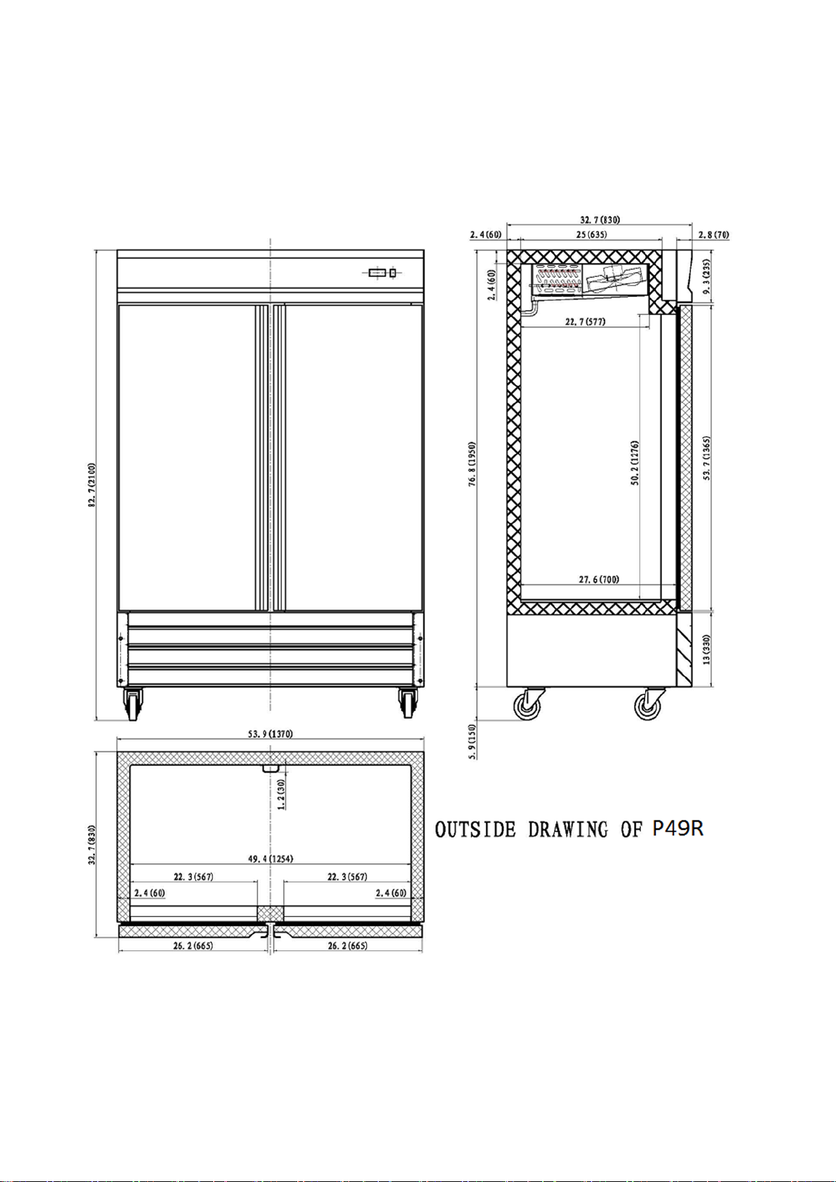
1-1. OUTSIDE DRAWING OF P49R
Page 4
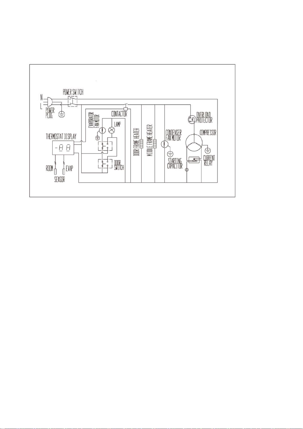
2. WIRING DIAGRAM
2-1. P49R
Page 5
3. PARTS DETAILS
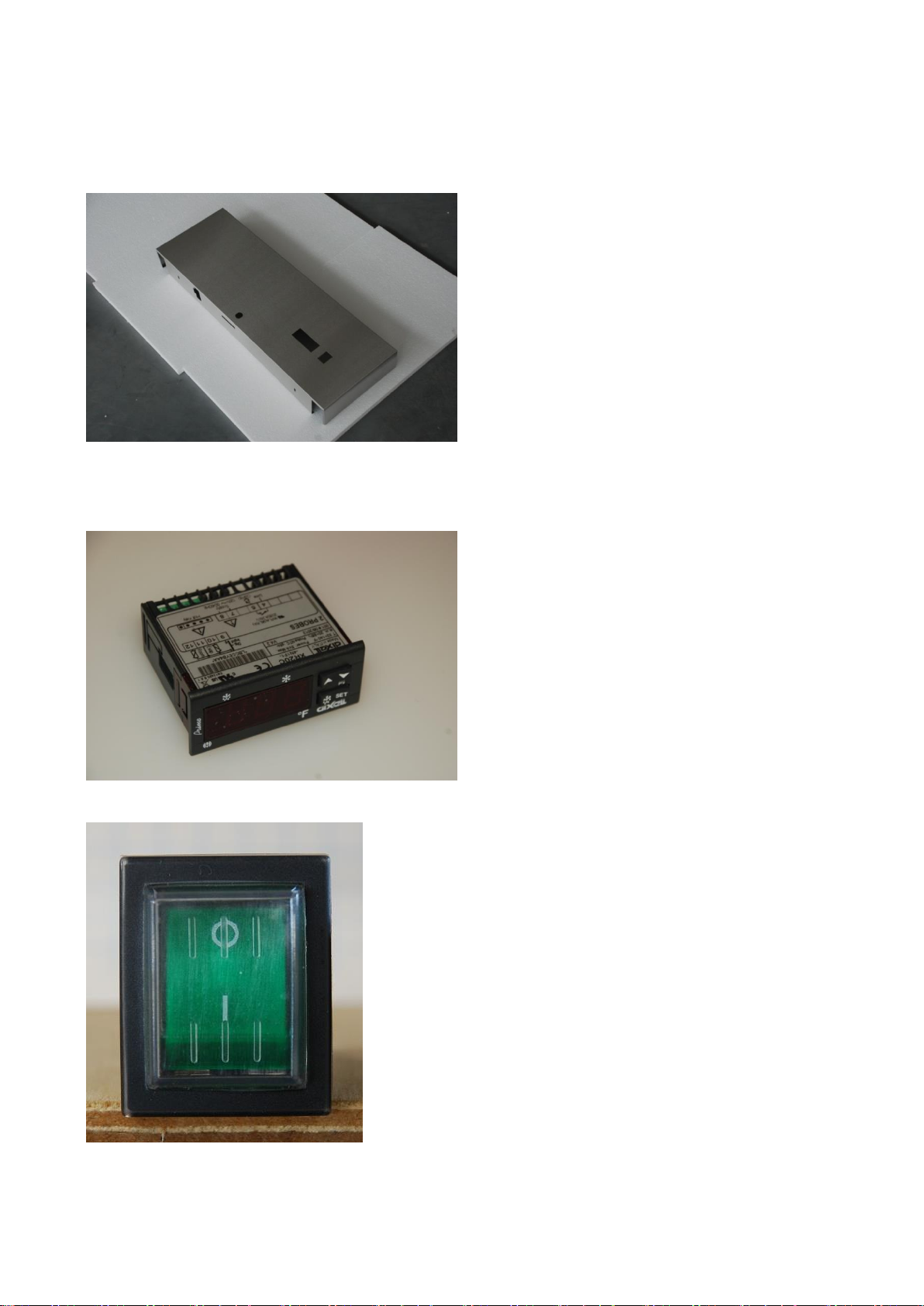
3-1. FRONT PANEL
THERMOSTAT
MAIN SWITCH
Page 6
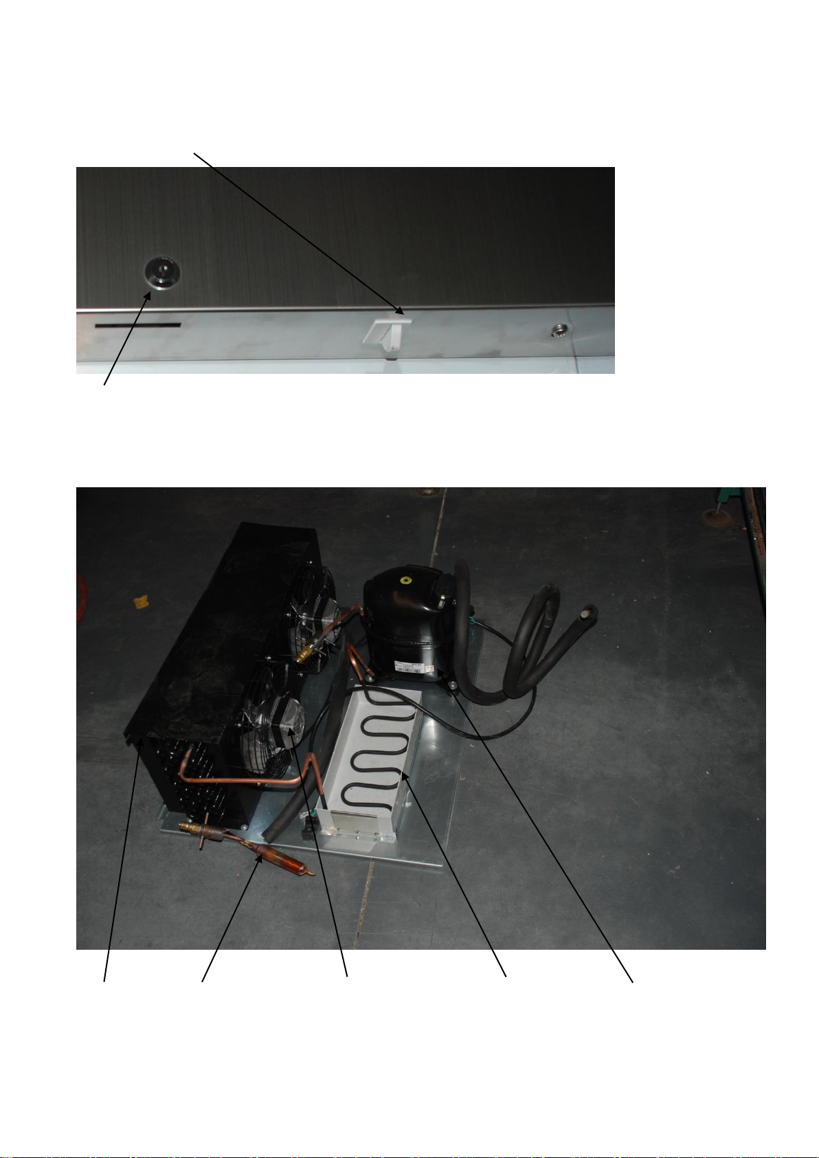
DOOR SWITCH
LOCK
3-2. REFRIGERATION COMPARTMENT CYCLE ASSEMBLY
CONDENSER FILTER DRIER CONDENSER FAN MOTOR WATER PAN COMPRESSOR
Page 7
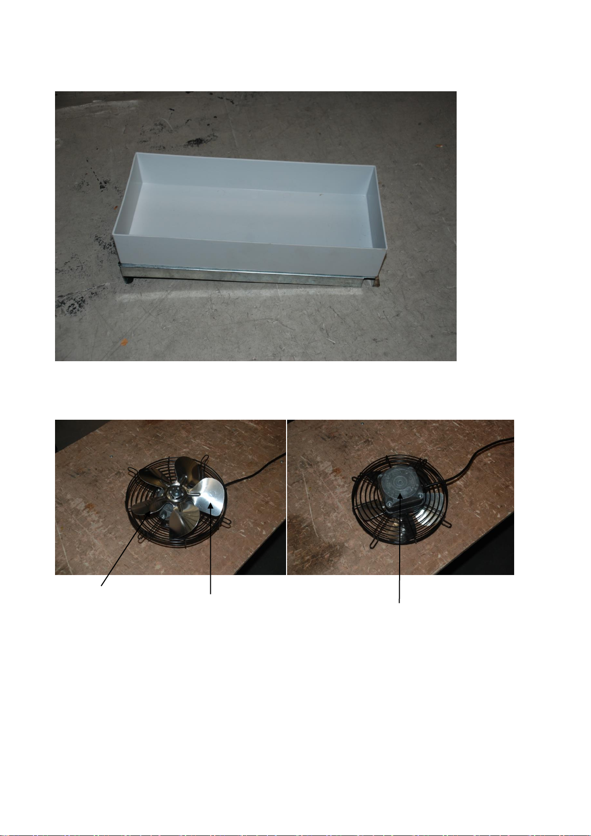
DRAIN PAN
CONDENSER FAN MOTOR ASSEMBLY
FAN COVER CONDENSER FAN MOTOR BLADE CONDENSER FAN MOTOR
Page 8

3-3. DOOR
GASKET
Magnetic gasket can be replaced without any tools.
Page 9

3-4. COOLING COMPARTMENT
Circle Fan Cover
Evaporator Fan Motor Blade Evaporator Fan Motor Fan Cover
Page 10

Evaporator Defrost Heating Element
Evaporator Fan Fan Support
Page 11

4. MAIN COMPONENTS
MODEL
P49R
Refrigerant
R-134a
Voltage
115V/60Hz
Comp.
Model
FFU130HAK
Part code
54R.15
P49R
Voltage
115V / 60Hz
Relay
Model
HLC-1XT04XA
Part code
27F.03
MODEL
P49R
Refrigerant
R-134a
Spec.
XH-9 25g
Part code
GN1410TN.14
MODEL
P49R
Voltage
115V / 60Hz
Running
X
Starting
378-454μf
MODEL
P49R
Voltage
115V / 60Hz
Motor
Model
CA27-04/C20
Part code
27R.30
4-1. COMPRESSOR
4-2. COMPRESSOR RELAY
4-3. CONDENSER DRYER
4-4. CAPACITOR
4-5. EVAPORATOR FAN MOTOR
Page 12

MODEL
P49R
Voltage
115V / 60Hz
Motor
Model
CA27-04/C19
Part code
27R.32
MODEL
P49R
Voltage
115V / 60Hz
Spec.
X
Part code
X
MODEL
P49R
Voltage
115V/60Hz
Spec.
25W
Part code
27R.29
MODEL
P49R
Voltage 115V / 60Hz
Part code
XR20CX
Micom
code
27R.10
4-6. CONDENSER FAN MOTOR
4-7. EVAPORATOR DEFROST HEATER
4-8. LAMP BULB
4-9. MAIN PCB
Page 13

5. ELECTRONIC CONTROLLER INSTRUCTION
NO.
Label
Name
Range
Hidden
Par.
Defa
ult
℃/℉
℃
℉
1
Set
Set point
LS-US
-5/23
0
32
2
Hy
Differential
0.1-25.5℃/1-
255℉
2/35.6 2.5
5
3
Ls
Minimum set point
-50℃-SET/-
58℉-SET
Yes
-50/58
-2
28
4
Us
Maximum set point
SET110℃/SET-
230℉
Yes
110/
230
10
50
5
Ot
Thermostat probe
calibration
-12-12℃/-
120-120℉
0/32 1 -1
6
P2P
Evaporator probe
presence
n=not
pres. ;y=pres
.
Y Y
Y
7
OE
Evaporator probe
calibration
-12-12℃/-
120-120℉
Yes
0/32 0 0
8
Ods
Outputs delay at start up
0-255min
Yes 0 2 2 9
AC
Anti-short cycle delay
0-50min
1 2
2
10
CCt
Continuous cycle
duration
0.0-24.0h
Yes
0.0
0.0
0.0
11
COn
Compressor ON time with
faulty probe
0-255min
Yes
15
10
10
12
COF
Compressor OFF time
with faulty probe
0-255min
Yes
30
10
10
13
CF
Temperature
measurement unit
℃/℉
Yes
℃/℉
℃
℉
5-1-1
DIXELL XR20C PARAMETER FOR NO.1
P49R
Page 14

14
rES
Resolution
in=integer;
dE =
dec .point
DE
DE
DE
15
Lod
Probe displayed
P1;P2
Yes
P1
P1
P1
16
EdF
Defrost termination
setting
Pb=by
temperature;
nP=by time
Pb
Pb
Pb
17
dtE
Defrost termination
temperature
-50-50℃/-58-
122℉
8/46.4 7
41
18
IdF
Interval between defrost
cycles
1-120ore
6 6
6
19
MdF
(Maximum) length for
defrost
0-255min
30
20
20
21
DFd
Display during defrost
rt, it, Set, DEF
Yes
Set
Set
set
22
dAd
MAX display delay after
defrost
0-255min
Yes
30
30
30
25
dAF
Defrost delay after fast
freezing
0-23h n
50’
Yes
0.0 0 0
30
Alc
Temperature Alarm
configuration
RE=related
to set;
Ab=absolute
Yes
Ab
re
re
31
ALU
MAX. temperature alarm
SET110℃/SET-
230℉
110/
230
50
90
32
ALL
MIN. temperature alarm
-50℃-SET/-
58℉-SET
-50/58
-40
80
33
Ald
Temperature alarm delay
0-255min
Yes
15 0 0
34
dAO
Delay of temperature
alarm at start up
0-23h n 50’
Yes
1.30 1 1
35
i1P
Digital input polarity
OP=opening
CL=closing
CL
CL
CL
36
i1F
Digital input configuration
EAL=extern.
alarm; bAL=
lock
regulation;
PAL=press.
switch; dor=
door
dor
dor
dor
Page 15

switchdEF=d
efrost; LHt
=disabled;
Htr=Coolingheating
37
did
Digital input alarm delay
0-255min
15
15
15
38
Nps
Number of activation of
pressure
0-15
Yes
15
15
15
39
odc
Compressor status with
open door
no,Fan=
normal; CPr=
comp.OFF;
F-C=
Compr.OFF &
fan.OFF
Yes
no
no
no
40
Pbc
Kind of probe
Ptc;ntc
ntc/
Ptc
ntc
ntc
41
dp1
Room probe display
-
Yes
P1
P1
P1
42
dp2
Evaporator probe display
-
Yes
P2
P2
P2
43
rEL
Software release
-
Yes
4.2
4.2
4.2
44
Ptb
Map code
-
Yes
83
83
83
5-1-2.
1. FRONT PANEL COMMANDS
To display target set point, select a parameter or confirm an operation in programming
mode.
To start a manual defrost
To view the last alarm occurrence. In programming mode, it browses the parameter
codes or increases the display value
To view the last alarm occurrence. In programming mode, it browses the parameter
codes or decreases the display value
KEY COMBINATION
To lock & unlock the keyboard
To enter in programming mode
To return to the room temperature display
1.1 Function of LEDS
Page 16

2. MAIN FUNCTIONS
2.1 HOW TO VIEW THE SET POINT
1. Push and immediately release the SET key: the display will show the set point value.
2. Push and immediately release the SET key or wait for 5 seconds to display the
sensor value again.
2.2 HOW TO CHANGE THE SET POINT
1. Push the SET key for more than 2 seconds to change the set point value.
2. The value of the set point will be displayed and the LED starts blinking.
3. To change the set value, push the or key within 10s.
4. To set new point value, push the SET key again or wait 10s.
2.3 HOW TO START A MANUAL DEFROST
Push the key for more than 2 seconds and a manual defrost will start
2.4 HOW TO LOCK THE KEYBOARD
1. Hold the and keys for more than 3s.
2. The “POF” message will be displayed and the keyboard will be locked. At this point, it will be
possible only to see the set point or the MAX or Min temperature stored.
3. If a key is pressed more than 3s the ”POF” message will be displayed.
2.5 HOW TO UNLOCK THE KEYBOARD
Hold the and keys together for more than 3s, till the “POF” message is displayed.
3. ALARM SIGNALS
HOW TO VIEW THE ALARM AND
RESET THE RECORDED ALARM
1. Hold the or key to
display the alarm signals.
2. When the signal is displayed, hold
the SET key until the “rst” message
is displayed. Push the SET key
again. The “rst” message will start
blinking and the normal temperature
will be displayed again.
Page 17

6. REPLACEMENT OF MAIN COMPONENTS
6-1. FRONT PANEL PARTS
UNSCREW THE FRONT PANEL
A. LIFT THE PANEL
Page 18

You can change the door switch, lock main switch and the thermostat here
6-2. REFRIGERATION COMPARTMENT PARTS
6-2-1. UNSCREW THE SENSOR CLIP AND TAKE THE SENSOR OUT FROM THE CLIP
Page 19

6-2-2. UNSCREW THE CIRCLE FAN COVER
6-2-3. PULL DOWN THE CIRCLE FAN COVER.
6-2-4. UNSCREW THE FAN SUPPORT
Page 20

6-2-5. CHANGE THE DEFROST HEATING ELEMENT
a. UNHOOK THE EVAPORATOR FROM ITS CASING
b. TAKE OFF THE ELEMENT AND REPLACE IT.
Page 21

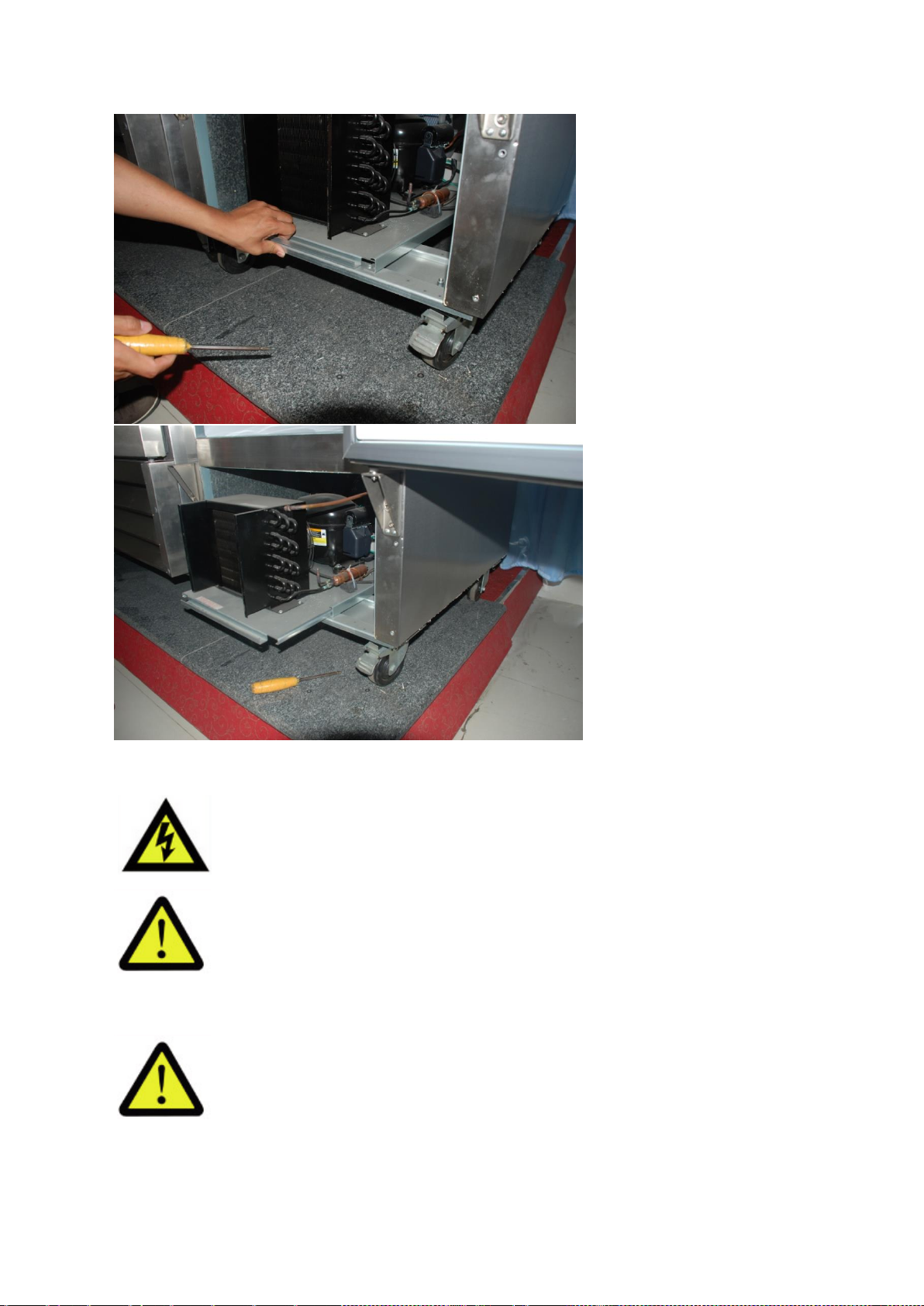
6-3. CONDENSING UNIT
6-3-1. TAKE OFF THE BOTTOM PANEL OF THE UNIT.
6-3-2. UNSCREW THE UNIT BOARD. YOU CAN PULL THE UNIT BOARD OUT FOR ANY
REPAIRS OR CLEANING.
Page 22
CAUTION: BE CAREFUL OF ELECTRIC SHOCK
CAUTION: MAKE SURE THE POWER SUPPLY IS CUT OFF
BEFORE ANY SERVICE IS PERFORMED
CAUTION: CONDENSING UNIT MAY BE VERY HOT. BE SURE
IT IS COOL BEFORE ANY SERVICE IS PERFORMED
 Loading...