

Saturn NHC 25B/30B/41B, NHC 25E/30E/41E, NHC 25H/30H/41H, NHC 25EH/30EH/41EH Instruction Manual
Installation, Maintenance and User Guide
Instruction Manual
Instruction Manual
Read the instructions fully before installing or using the appliance.
INSTALLER, this manual is to be axed adjacent to the boiler.
CONSUMER, retain this manual for future reference purposes.
Constant development eorts may result in minor deviations in
illustrations, functional steps and technical data without prior notice.
Pictures and drawings in the instructions can be dierent from the
appliance. All product images are provided by the manufacturer and are
for reference purposes only.
NHC 25B/30B/41B (Boiler House w/ Combi Option)
NHC 25E/30E/41E (External w/ Combi Option)
NHC 25H/30H/41H (Boiler House w/ Heat Only)
NHC 25EH/30EH/41EH (External w/ Heat Only)


Contents
Homeowner
4
5
6
7
8
9
10
11
12
13
14
18
20
22
23
24
26
30
31
36
37
42
43
44
45
Safety instructions
Product Fiche
Operation & Display Panel (OBC100)
Room Thermostat (LCR-2WE) - Combi Only
Vacation/Standby Mode - Combi only
Heating Mode - Combi only
Hot water Mode - Combi only
Fault Codes
Installer
Design Standards
Safety
Flue Regulations
Before Using The Boiler
How To Use
Safety Devices
Everyday Checks
Servicing The Boiler
Plumbing Schematic
Commissioning The Boiler
Component Overview
Electric Wiring Diagram
Wiring - Installation Variations
OTC Mode
Troubleshooting
Fault Codes
Product Information
Spare Parts
Specifications
Warranty
46
49
50

4
Safety Instructions
Safety-related messages and instructions have been provided in this manual
and on the boiler to warn you and others of a potential injury hazard. Read
and follow all safety messages and instructions throughout this manual.
It is very important to understand this safety section for operating,
installing and servicing of the boiler.
In addition to this, under the Consumer Protection Act 1987 and Section
6 of the Health & Safety Act 1974, we are required to provide
information on substances hazardous to health.
The small quantities of adhesives and sealants used in the product are
cured. They present no known hazards when used in the manner for
which they are intended.
This is a safety ale
rt symbol. It is used to alert you to potential
personal injury hazards.
Obey all safety messages that follow this symbol to avoid
possible injury or death.
Indicates an imminently hazardous situation which
if not avoided, could result in severe injury or death.
Indicates a potentially hazardous situation which,
if not avoided, could result in severe injury or death.
Indicates an imminently hazardous situation which,
if not avoided, could result in minor moderate injury.
Earth
Use of fire
forbidden
Dangerous
electric current
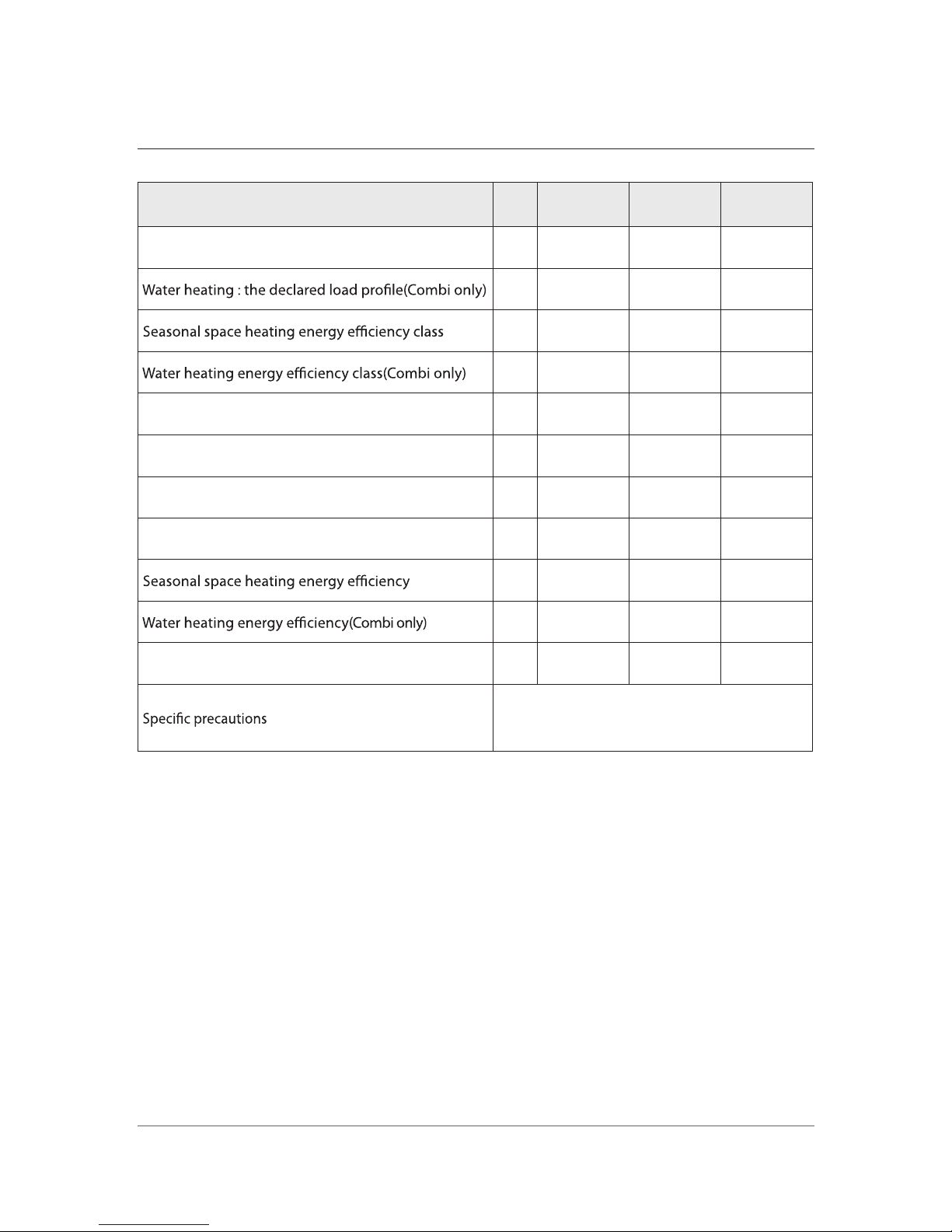
Product Fiche
5
KD Navien Unit NHC 25B NHC 30B NHC 41B
Space heating : temperature application Medium Medium Medium
XL XL XXL
A A A
B B B
Rated heat output kW 24.0 27.9 36.8
Space heating : annual energy consumption kWh 76 89 116
Water heating : annual electricity consumption(Combi only) kWh 94 93 105
Water heating : annual fuel consumption(Combi only) GJ 22 23 30
% 91 90 91
% 64 62 67
Sound power level dB 68 66 69
Read the user's information and installation
manual before the application is assembled,
installed or maintained.
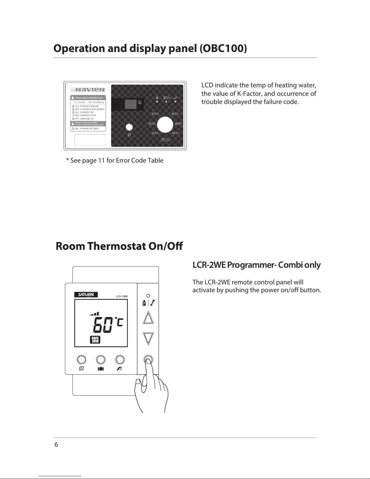
LCD indicate the temp of heating water,
the value of K-Factor, and occurrence of
trouble displayed the failure code.
* See page 11 for Error Code Table
LC
R-2WE Programmer- Combi only
The LCR-2WE remote control panel will
activate by pushing the power on/off button.
6
Operation and display panel (OBC100)
7
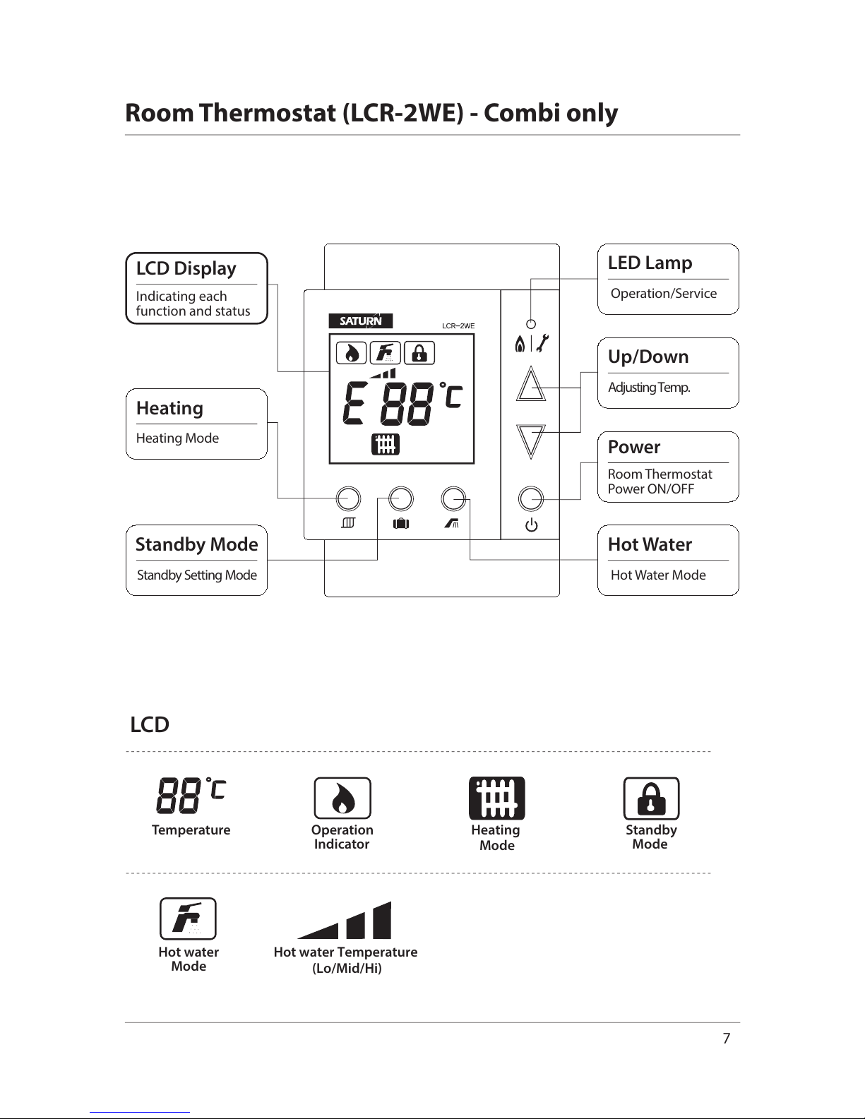
Hot water Temperature
(Lo/Mid/Hi)
Standby
Mode
Heating
Mode
Hot water
Mode
Temperature Operation
Indicator
Indicating each
function and status
LCD Display
Room Thermostat
Power ON/OFF
Power
Heating Mode
Heating
Adjusting Temp.
Up/Down
Standby SettingMode
Standby Mode
Hot Water Mode
Hot Water
Operation/Service
LED Lamp
Room Thermostat (LCR-2WE) - Combi only
LCD
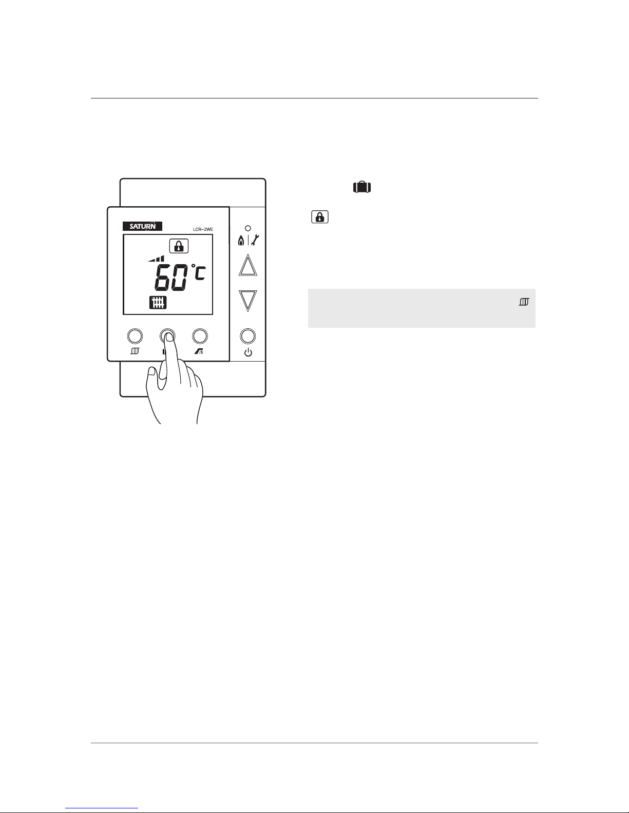
If you are not at home, you can set the Standby Mode to save heating
energy by pressing.
To cancel vacation/standby mode press the
button to return to the heating mode.
will be displayed and Standby Mode
will be set.
Press button.
8
Vacation/Standby Mode - Combi only
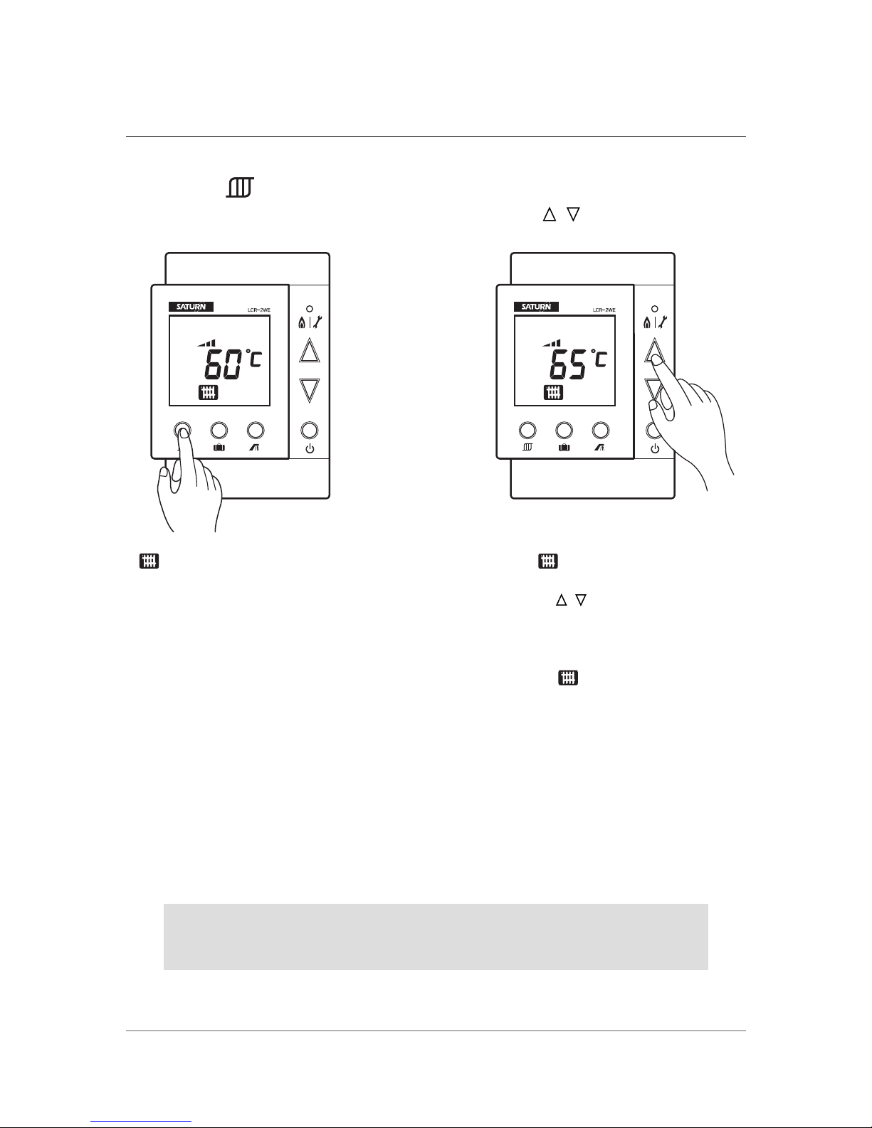
blinks when selecting
Boiler Temp. Mode
when blinks, set the desired
boiler temp. between 40~80˚C by
adjusting / button, after a while,
it is automatically saved. Boiler
temp. can be set by 1˚C. After the
required temperature has been
selected, is on and current
boiler water temp. is displayed.
Set the heating temp.
with / button.
Press the button.
The LCR-2WE room thermostat is designed to control a heating system
according to time and temperature, in connection with a valve controller
(red colored cable).
9
Heating mode - Combi only
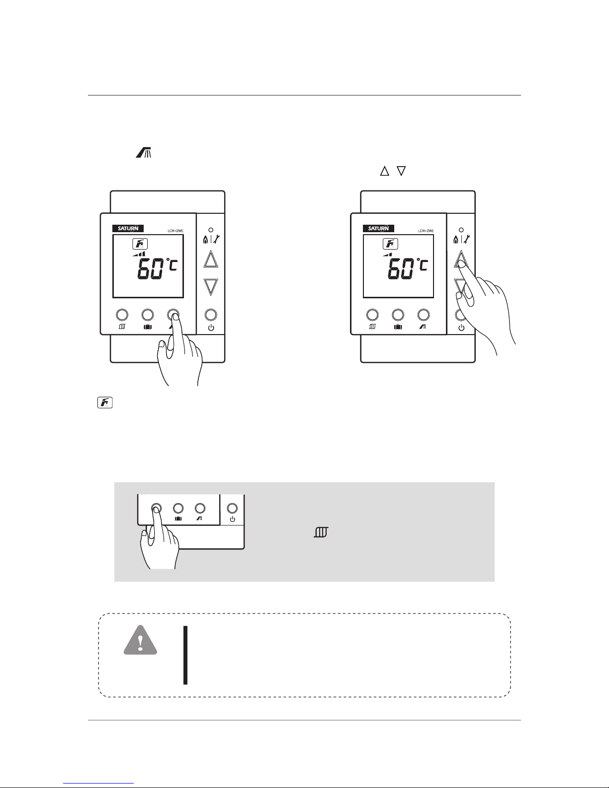
will be displayed and
Hot Water Mode will be set.
Adjusting hot water temp. by
3step; Low load, Medium load,
High load capacity of
combustion.
Set the heating temp.
with / button.
Use this function only when hot water is needed.
1. Please be careful that infants and young children do not use
hot water without a guardian present.
2. While others are using hot water, do not change the hot
water temp. setting for safety.
CAUTION
Press button.
You can determine whether the changeover
from DHW mode to Heating mode by
pushing “ " button.
1
0
Hot Water Mode - Combi only
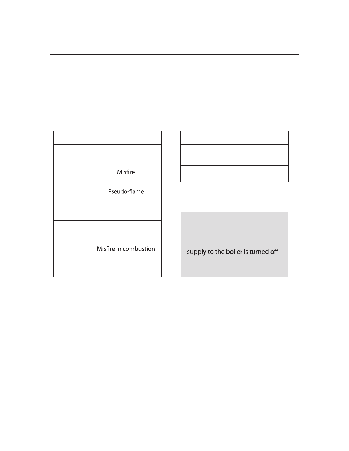
Fault at the boiler
Fault codes take priority over all other display functions in the event of a system
fault occurring and the LCD shows one of the following numeric error codes.
If multiple faults occur, the corresponding fault codes are displayed alternately
for about two seconds each.
To reset the boiler switch the power button on -> off -> on.
If problem persists, contact your local installer.
02
03
04
05
06
12
16
Low water level
Temp. sensor wire
disconnected
Short circuit of
Temp. sensor
High limit thermostat
Error Code
Cause
Fault at the room controller
51
52
Electrical backup system
failure
Functional button
defective
Error Code
Cause
Electrical backup
The LCR-2WE retains the setting
parameters when the power
or shut down by power outages
and back to the preset operation.
11
Fault Codes

12
Design Standards
EMC Directive (Electromagnetic compatibility) 89/336/EC
Standards:
EN 61000-6-1: Electromagnetic Compatibility Generic Standard –
Immunity for residential, commercial and light industrial environments.
(Feb 2001)
EN 61000-6-3: Electromagnetic Compatibility Generic Standard – Emission
standard for residential, commercial and light industrial environments.
(Feb 2001)
LV Directive (Low voltage) 73/23/EEC
Standard:
EN 60335-1: Household and similar electrical appliances - Safety (May
2001)
Boiler Efficiency Directive 92/42/EEC
Standard:
BSEN 304: Oil boilers with forced draft burners.
Fuel Spillage
1. Switch off all electrical and other ignition sources.
2. Remove all contaminated clothing to safeguard against fire risk and skin
damage. Wash affected skin thoroughly with soap and water and remove
clothing to a safe well ventilated area and allow to air before cleaning.
3. Contain and smother the spill using sand or other suitable oil absorbent
media or non-combustible material.
4. Do not allow fuel to escape into drains or water courses. If this happens,
contact the relevant authorities in your area. (Ireland only). Contact the
Environment Agency on 0800 807060 (UK Only)
5. Consult local authority about disposal of contaminated soil, see
http://www.housing.gov.ie/local-government/administration/localauthorities/local-authorities
INSTALLER SECTION

13
Safety
Safe use of kerosene.
These fuels give off a flammable vapour when heated moderately. Vapour ignites
easily, burns intensely and may cause explosion. The vapour can follow along at
ground level for considerable distances from open containers and spillages
collecting as an explosive mixture in drains, cellars, etc.
Fuel
s remove natural oils and fats from the skin and this may cause irritation and
cracking of skin. Barrier cream containing lanolin is highly recommended together
with good personal hygiene and where necessary appropriate personal protection
equipment. (P.P.E.) Gas oil may also cause irreversible damage to health on
prolonged or repeated skin contact.
Alwa
ys store fuels in a properly constructed and labelled tank. Always handle fuel in
open air or well ventilated space away from sources of ignition and refrain from
smoking.
Alwa
ys drain fuel using a proper fuel retriever, funnel or mechanical siphon. Never
apply heat to a fuel tank, container or pipework. Never siphon fuel through tube by
mouth. If accidentally swallowed contact doctor immediately and do NOT induce
vomiting. Avoid inhaling fuel vapour as this can cause light headedness and
seriously impair judgement.
First Aid
If fuel is accidently swallowed:
Seek medical attention immediately and DO NOT induce vomiting.
If fuel is splashed into your eyes:
Wash out with running water for at least ten minutes and seek medical attention as
soon as possible.
14
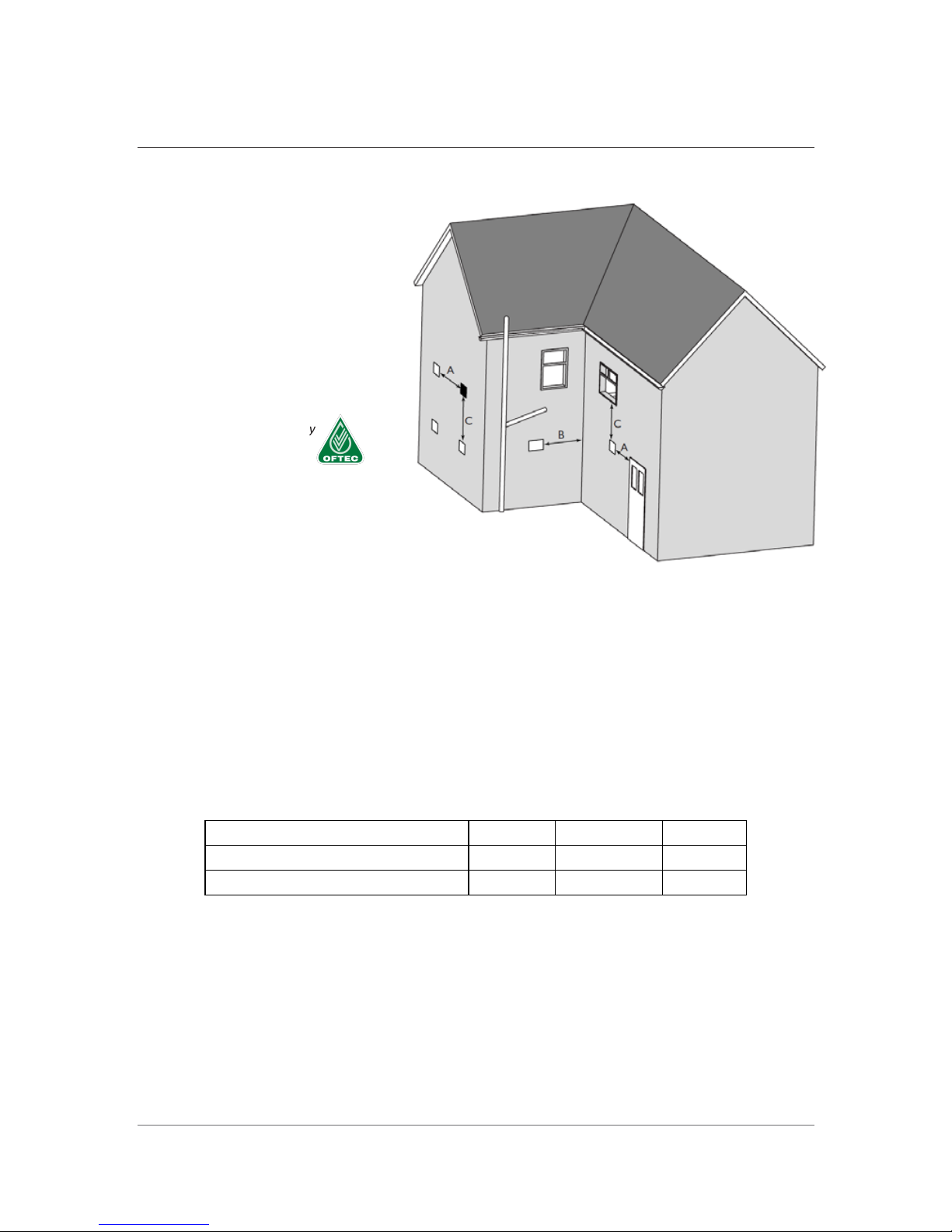
Flues Regulations
Balanced Flue Siting
Note:
1. Terminal should be positioned to avoid combustion products entering the building
or accum
ulating in stagnant pockets around buildings.
2. The terminal must be protected by a guard if it is less than 2 metres above ground
level or in a position where any person has access.
3. A heat protection shield should be fitted if the terminal is less than 850mm from a
plastic or painted gutter or less than 450mm from painted eaves.
Saturn Heating recommends as per OFTEC recommendations that the flue should
be a minimum distance of 1 metre from openings so that it does not cause a
nuisance and permits the dispersal of combustion products.
Building Regulations
A B C
Northern Ireland 600 600 600
Republic of Ireland 600 600 600
Where the terminal is within 1 metre of any plastic material, such material should be
protected from the effects of combustion products of fuel. There are additional general
requirements in most regulations and standards that the flue must be positioned so that it
does not cause a nuisance and permits the dispersal of combustion products.
Note:
The Building Regulations clearances shown above are the minimum allowed.
Contact Saturn Heating Technical Department for futher advice in this regard.
ALWAYS CHECK FOR ANY BUILDING REGULATIONS AMENDMENTS WHICH
MAY HAVE BEEN ISSUED AFTER THE PUBLICATION OF THIS MANUAL
a) Horizontal from opening,
airbrick, opening window
etc.
b) From an internal or external
corner.
c) Below an opening, airbrick,
opening window etc.
Information supplied by
Book Four, 2010.
Please see note at foot of page.
15
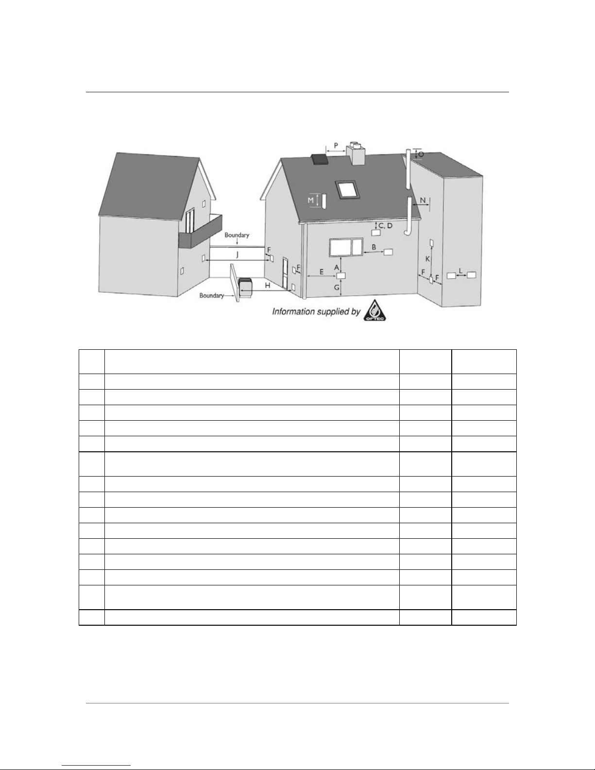
Flues Regulations
Clearances advised by the British Standards, provided by OFTEC, for open flues, low level
balanced flues and balanced flues fitted to oil fired boilers.
Minimum distances to terminals in millimetres as measured from top of the chimney or
the rim of a low level discharge opening.
Aplliance Burner Type
Pressure
Jet
Vapourising
A
Directly below an opening, air brick, opening window etc
600
Not allowed
B
Horizontally to an opening, air brick, opening window etc
600
Not allowed
C
Below a gutter, eaves or balcony without protection
75
Not allowed
D
Below a gutter or a balcony without protection
600
Not allowed
E
From vertical sanitary pipework
300
Not allowed
F
From an internal or external corner or surface or boundary
alongside the terminal
300
Not allowed
G
Above ground or balcony level
300
Not allowed
H
From a surface or boundary facing the terminal
600
Not allowed
J
From a terminal facing a terminal
1200
Not allowed
K
Vertically from a terminal on the same wall
1500
Not allowed
L
Horizontally from a terminal on the same wall
750
Not allowed
M
Above the highest point of an intersection with the roof
600
1000
N
From a vertical structure on the side of the terminal
750
2300
O
Above a vertical structure less than 750mm from the side of the
terminal
600
1000
P
Directly below an opening, air brick, opening window etc.
1500
Not allowed
Notes:
- Terminals should be positioned so as to avoid products of combustion accumulating in
stagnant pockets around the building or entering into buildings.
- Appliances burning Class D oil have additional restrictions (See OFTEC Book 4 2010)
- Vertical structure in N, O and P include tank or lift rooms, parapets, dormers etc.
16
Flues Regulations
- Terminating positions A to L are only permitted for appliances that have been approved
for low level flue discharge when tested to OFS A100 or A101
- Terminating positions must be at least 1.8 metres distant from an oil storage tank unless
a wall with at least 30 mins fire resistance and extending 300mm higher and wider than the
tank is provided between the tank and the terminating position.
- Where a flue is terminated less than 600mm away from a projecti
on above it and the
projection consists of plastic or has a combustible or painted surface, then a heat shield of
at least 750mm wide should be fitted to protect these surfaces.
- For terminals used with vapourising burners, a horizontal distance of at least 2300mm is
required between the terminal and the roof line.
- If the lowest part of the terminal is less than 2 metres above the ground, balcony, flat
roof or other place to which any person has access, the terminal must be protected by a
guard.
- Notwithstanding the dimensions given in the drawing and table, a terminal should not be
sited closer than 300mm to combustible material.
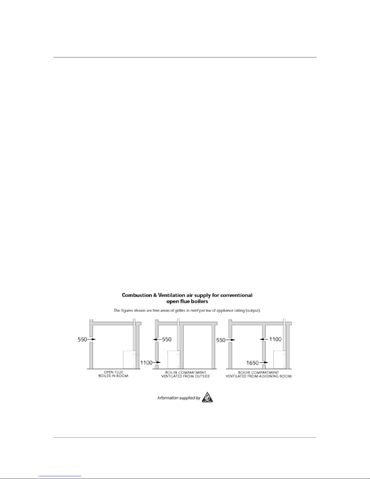
Ventilation & Combustion Air
Conventional Flue Boilers
An adequate supply of combustion and ventilation air is essential for efficient and safe
boiler operation and the openings for this should be positioned to cause least possible
draught, with no possibility of being accidentally blocked. Please note, the British Standard
Code of Practice for Oil Firing BS5410:Part 1, requires a permanent air inlet opening of
550mm
² per kW (above 5kW) of boiler rated output. (Note: 1kW = 3412 Btu/h).
Also when the boiler is installed in a compartment or confined space, ventilation openings are
required to ventilate and to avoid overheating in the boiler area.
FULL TEXT of both BS 5410 Part 1: 1997 and appropriate Building Regulations for each country
should be obtained and fully applied.

17
Flues Regulations
N.B. Please Carefully Note:
In OFTEC Book Four, 2010 page 33, 6.6.5 states that for the Republic of Ireland, “It is
not permitted to install open flue appliances in domestic garages, therefore only room
sealed balance flue appliances should be installed in a garage location”
Definitions:
Combustion Air:
Air required directly by boiler oil burner for combustion process.
Ventilation Air:
Air required in the room for ventilation, cooling, etc. and to promote a
healthy living environment.

Check all pipe connections thoroughly for
leaks before start-up.
Before using the boiler
18
Fuel
It is essential to use only
kerosene or light oil.
It is better to use kerosene when the temperature
can drop below -5 ˚C.
Choose a fuel storage location in accordance with
local regulations (See page 14 - Flue Regulations).
Take care to avoid the ingress of water and/or dirt
during re-lling as this can lead to f lame failure or
aect the lifespan of the boiler.
Ensure that the power is turned o and
the oil tank is isolated before relling.
A fuel filter with a filter rating of 70microns or
better must be fitted to the fuel supply, to the
appliance.
Pre-Start Checks

and that the low water level alarm is not activated.
suitable measurement equipment to ensure
correct combustion is taking place.
Do not plug out the power supply as this will
de-activate the frost protection.
The domestic hot water supply is not
recommended for potable use.(Combi only)
19
Notes when using
Take care when positioning
the boiler.
Do not locate in the immediate
vicinity of flammable materials.
Avo o e e oe

Avoid complete emptying of the oil tank.
This can lead to air being introduced to
the fuel system and may result in ignition failure.
the fuel supply line to vent. When oil starts to
In negative head oil supply applications the
fuel supply line must be purged using the
screw must be in the tightened position.
oil pump vent screw. For this the oil lter
Open the oil pump vent screw and switch
on the power to the boiler. After 6-7 seconds
the pump has purged the air and the
“CHECK”light will show on the control panel.
The boiler will stop.
Loosen the screw in the oil lter. This will allow
ow re-tighten the screw (this is only possible
in positive head oil supply applications).
How to use
20
Purging the oil supply

Ensure the system is full and at suitable
operation pressures. Fill and thoroughly
purge all connected pipework.
21
Reset the boiler by turning the power off and on.
Close the oil pump vent, press the power button
again and the boiler will ignite. If the boiler fails to
fire after 3 successive attempts contact the Saturn
technical helpline on 1890 929 112.
Preparation and checking before start-up
The boiler must always be correctly
grounded according to relevant local regulations.
Connect the boiler to the main 220v supply
and press the power button. The “RUN”
light should show after a short period.
Volt free boiler call (Orange cable)
Warning: Connecting power to this cable will
damage the boiler control panel.
Full wiring instructions on pages 36-41

When the boiler does not ignite, or if the flame
falls the flame detector (photocell) will
deactivate
the boiler.
Ignition safety device
Low water level safety device
2
2
Safety devices
If the water level is insufficient in the boiler
the low water level sensor will deactivate
the boiler. Once the system is adequately
refilled this will automatically reset.
Overheat prevention
If the temperature of the boiler rises to
dangerously high levels the overheat
sensor will deactivate the boiler.
In this instance the “CHECK” light will show. To
reset press the “RESET” button on the overheat
preventer.
Frost freezing prevention
At a boiler temperature of 9°C the circulating
pump will be activated. At a boiler temperature
of 2°C the burner will ignite. For this reason,
power must be maintained to the boiler, even if
the system is not in use.
Power-failure protection
In the event of power failure the oil supply will
automatically be isolated from the combustion
chamber.

Ensure that combustible materials are
not stored near the boiler.
Check for fuel leaks within the fuel
storage/supply system and check for
water leaks within and around the boiler.
Inspect the inside of the oil tank
for water or debris.
Keep
the area around the boiler clean and free
from obstruction to allow for free air flow.
2
3
Everyday checks
Points to be checked once or more a year

Soot build-up within the boiler will reduce its
The boiler should be serviced annually
by an approved service engineer.
Cleaning of the boiler
Wash the filter and the inside of the coil
cup using clean kerosene.
The oil tank should be checked during the
annual service and cleaned of all water
and debris as required.
Cleaning the oil filter
Cleaning the oil tank
24
To clean the oil filter, first isolate the oil supply.
Remove the oil cup
by unscrewing and pulling
the cup downwards.
Servicing The Boiler

If the flame detector (photocell) becomes sooty
or dirty the reduced sensitivity will cause erratic
and
incorrect boiler operation.
Cleaning the flame detector
Remove the flame detector (photocell) which
is located at the
top of the burner.
Wipe the glass surface
of the flame detector
(photocell) using a clean rag and replace.
During the annual service the flue system should
be checked for correct
installation, blockages,
corrosion or leakage. Any abnormalities found
should be rectified immediately.
Checking the flue pipe
25

Open cistern tank
Never install any valve between
boiler and cistern tank
Supply Water
Pipe
Minimum 1.5m
Circulating Pump
Distributor
Distributor
Condensate
Outlet
Drain Drain
F.L
Expansion Tank
Combi only
Water
Cold Water Inlet
Heating Flow
Heating Return
Cold Water
Hot Water
Boiler Back
2
6
Plumbing Schematic
Choosing of the installation place
Choose an installation site that allows easy access for installation, maintenance and operation.
When choosing an installation site, take care to conform to all local regulations and standards.
Allow as much free space around the boiler as possible for maintenance and reduced fire
hazard. Ensure that the boiler is accessible in order to allow for easy adjustment of the boiler
temperature.
The boiler should not be sited close to storage areas of combustible materials.
Consider condensate and boiler drainage requirements when choosing the boiler location.
Installation diagram : Cistern tank install type
Heating Coil
Fan Coil
Radiator

1. The system should be installed with a pressure safety valve rated to 3.5 Bar or less.
2. The maximum operating pressure is 3.5 Bar. Neither the boiler nor any connected pipe
work should be exposed to pressures in excess of this.
3. Always install the boiler and the connected system according to local regulations.
Sealed System
Precautions
Safety Valve
Air Exhaust Valve
Filter
Reducing Valve
Check Valve
Circulation Pump
Distributor
Condensate
Outlet
Drain Drain
F.L
Sealed Expansion Tank
Install the condensate outlet hose as above
Water
Cold Water Inlet
Hot Water Outlet
Heating Water Outlet
Cold Water
Hot Water
Heating Coil
Fan Coil
Radiator
Boiler Back
Combi only
27

It is recommended that the ue system not exceed 7 metres in length and that no
more than 2 bends be used. Subtract one metre for every 90° bend and 500ml for
every 45° bend.
Condensing boiler model : NHC25B/30B/41B
Flue Installation
Allowing combustion gas to re-enter the
boiler room can result in a build up of
carbon monoxide, which could result in
poisoning. Saturn recommends the
installation of a suitable carbon monoxide
detector on all installations.
CAUTION
VENTILATING OPENING
10˚ OVER
300mm OVER
AIR INLET
FIREPROOF INSULATION
MATERIAL
150mm OVER
FIREPROOFINSULATION
MATERIAL
FIREWALL, SEMIFIRE WALL
The flue should be installed at an angle of no more than 10°. The flue should be
made
from heat-resistant non-corrosive material.
28
Example of a standard installation

1. Condensate is produced when the condensing boiler is running and should be
piped to the drainage system.
2. Link the drain hose with the outlet of the neutralization system which is located at
the bottom of boiler and then connect the end of the hose to a soak pit.
3. Please make sure that the neutralizer in the boiler is filled with water.
4. The condensate drain system should be installed to minimise the risk of freezing.
Ensure the condensate is sent
to a suitable waste outlet in
accordance with regulations.
29

Commissioning The Boiler
30
1. Prime the boiler with kerosene and press the power button on, ensuring there
is a heat request from your time clock. The boiler then takes 3 attempts to go
into ignition phase.
2. The fan will start up and purge the air through the heat exchanger
- Troubleshooting if sequence missed:
• No heat request, or incorrect wiring, please refer to "Wiring The Boiler"
3. The transformer will begin to generate a spark at the electrodes
- Troubleshooting if sequence missed:
• Photocell disconnected/dirty: reconnect/clean
4. The oil pump will engage to pump oil to the burner
- Troubleshooting if sequence missed:
• Not fully primed with oil bowl filled and oil line clear of air
• This will be apparent by the pump making a loud noise
5. Successful ignition can be seen through the sight glass
All boilers come pretested from the factory, so minimal adjustments are
needed on commissioning. Using a flue gas analyser, you are looking for the
following read outs:
- 11.5% Co2
- 50-60 PPM
Simply adjust the damper opening on the burner to achieve these numbers

Component Overview
31
The structure of the boiler
ModelNo: NHC 25B/30B/41B
Neutralizer assembly
Burner Assembly
Return water pipe for space
heating
Electronic pump &
Oil filter
Overheat preventer
Low water level sensor
Temperature sensor
Controller
Heat Exchanger
FE flue, Φ75

Component Overview
32
The structure of burner
ModelNo: NHC 25B/30B/41B
Damper
Fan 3
Fan 2
Fan 1
Fan Causing
Fan Motor
Ignition Electrode
Blow tube & ame holder
Air holder
Nozzle
Inner tube
Flame detector

Component Overview
33
The principle of the burner
ModelNo: NHC 25B/30B/41B
Construction of Burner
Air Flow
Oil Fluid
Air Flow
Oil inlet
1) Fan (motor) working
2) Ignition transformer is working
3) Electronic pump is working ; oil
pressure increase
4) Sensing combustion and
flame
5) Continuous combustion
Burner Running Mechanism
Flame holder : Oil & air mixing zone
Air holder : assist the ignition

Component Overview
34
The structure of the heat exchanger
ModelNo: NHC 25B/30B/41B
Bae plates
H.E. for DHW
Combustion chamber
Straight pipes
ýNHC-25H/30H/41H doesnot come with an in-built DHW heat exchanger.
ý
NHC-25EH/30EH/41EH doesnot come with an in-built DHW heat exchanger.

Component Overview
35
The principle of the heat exchanger
ModelNo: NHC 25B/30B/41B
Construction of Condensing Boiler
Heat Fluid
Heat transfer Fluid
Figure of Heat transfer method
Parallel Flow Counter Flow
Counter Flow
Condensate outlet
Chamber Temp. about 800 C
Fluid Flow
200 C under
75 C under
Counter Flow : 2 times
Parallel Flow : 1 time
ýNHC-25H/30H/41H doesnot come with an in-built DHW heat exchanger.
ýNHC-25EH/30EH/41EH doesnot
c
ome with an in-built DHW heat exchanger.

3
6
Color : White
1
A
B
6
4
C
531
642
BLACK TUBE
Orange
Blue
A
B
C
A
B
C
Blue
D
5
3
01
11
02
12
03
13
04
14
05
15
16
17
06
18
07
19
08
20
09
10
21
White
Red
Red
Black
Skyblue
Brown
Yellow
Green + Yellow
EARTH
LOW WATER SENSOR
HIGH LIMIT STAT
Black
Black
Skyblue
Brown
Brown
Black
Blue
Brown
OIL PREHEATER CABLE
CIRCULATION PUMP
Blue
Brown
HEATING WATER TEMP. SENSOR
VOLT-FREE HEAT REQUEST
D
D
C
C
OIL PUMP
Blue
Brown
Power cord
Green + Yellow
Blue
Yellow
[BOILER]
[BURNER]
Brown
OUTDOOR TEMP. SENSOR
AUXILIARY SENSOR
Black
BOOSTER PUMP
1
4
6
4
6
5
3
1
5
3
Electric wiring diagram
Blue
Brown
Green + Yellow
(White)
WEATHER
COMP MODE
WEATHER
COMP MODE
(White)
ModelNo: NHC 25B/30B/41B

37
Electric Wiring – Installation Variations
Note:
Boiler temperature display will only be shown when there is a heat request
through the switch live as permanent supply has not been provided.
3 Core Wiring Diagram
(Warning, without permanent supply, the frost stat is disabled)

38
Electric Wiring – Installation Variations
Note:
Due to the above setup using a 230v switch live, for a heat request from the
boiler, an NO stepdown relay or a motorised valve is needed to connect into
the low voltage heat request orange cables.
4 Core Wiring Diagram

39
Electric Wiring – Installation Variations
Note:
Simply
join single auxiliaries from multiple MV’s and bring to the boiler in 2
core fashion. If any MV opens, the volt free auxiliary will call for a heat
request.
5 Core Wiring Diagram

40
Electric Wiring – Installation Variations
Note:
Simply connect the volt free orange heat call to the back of the combi
controller, and now the red cables coming from the controller, by
extension, become your low voltage heat call.
5 Core Wiring Diagram - Combi Only

41
All wiring must be in accordance with its instructions for connections with the valve
controller properly and unused wire should be insulated and short-circuited.
1. Connect the cables of room thermostat properly to the terminal of valve contoller
in accordance with following each colored cable;
- Red : Heating
- Blue : Fault signal
(NA)
- Yellow : Combus
tion signal (NA)
Unused wire should be insulated and short-circuited.
2. The pin rail on the back of the thermostat must connect to 2 orange cables from the boiler.
3. Fix the wall socket with the screws provided.
Boiler
AC 220V
Main Controller
Valve Controller
Red wires
Auxillary wires
L
N
MV
Room thermostat
Input/output
terminal
Room thermostat (LCR-2WE) - Combi only
4. Carefully push and t the thermostat on to the wall socket until it clicks in position.

42
OTC Mode
If a
n outdoor temperature probe is connected, the weather compensation
function can be used in conjunction with the weather comp' relay available at
your local Saturn stockist .
1) With this function, the target primary temperature is automatically
set according to the outdoor temperature (K-Factor).
2) When the outdoor temperature sensor is connected, OTC lamp is turned on.
3) The outdoor temperature sensor should be placed in an area to avoid
temperature fluctuations caused from direct sunlight. Preferable the sensor
should be located in a north facing location.
K-Factor

43
1. Check that the Outdoor Temp
sensor has been connected properly.
2. Check the OTC mode is working by
returning to Central Heating mode
(Press the Mode button repeatedly,
until or is displayed.)
※ Please contact Saturn Technical department for any unclear matters.
1. On pressing the
power button, the
motor doesn’t work
2. The motor rotates,
but the boiler doesn’t
ignite
3. The boiler ignites, but
immediately stops
4. The electronic pump
makes noise
2.
Check and clean electrode.
Check nozzle and change if
necessary.
6. Smoke and soot
build up
1.
2.
The oil is bad or has impure
materials.
The
air for combustion is
short.
1.
2.
Replace the oil.
Check external filter bowl.
1. The oil valve is locked.
2. There is no oil in the tank.
3. There is air in pipes.
4.
1.
2.
3.
4.
1.
2.3.There is air in the oil line.
The oil tank is empty.
1.
Open the valve.
2. Supply oil.
3.
4. Clean the boiler.
1.
2.
3.
1.
2.
1.
2.
3. No heat request.
1.
2.
This is not a problem.
When the temperature of the
boiler goes down, it will restart.
Check 5 AMP fuse spur/power.
3. Check time clock and stats for
heat request.
Happening Cause Solution methods
8. The appliance does not
go into OTC mode
1.2.The Outdoor Temperature
sensor is not connected
correctly.
Hot Water activation
Troubleshooting
The temperature in the
boiler is abov
e the set
temperature.
No power.
The oil in the oil tank is
insucient.
The ame detector
cannot sense.
The oil lter is blocked.
Impurities in the oil.
Supply more oil.
Clean the ame detector.
Clean the oil lter.
Replace the oil with good oil.
4.
The oil lter is blocked. Clean the oil lter.
Vent the oil line.
3. Ref i ll the oil tank.
5. On igniting, it backres
1.
Electrode fault.
OTC Mode turns o during
Dirty nozzle.
2.
1.

44
Fault Codes
When an error occurs, the LCD shows one of the following numeric error codes
with letter ’E’.
Error Code
Cause
02
03
04
05
06
12
16
Low water level
Temp. sensor wire
disconnected
Short circuit of
Temp. sensor
High limit thermostat
Flame failure
Misre in combustion
Misre

45
Product Information
KD Navien
symbol Unit NHC 25B NHC 30B NHC 41B
Condensing boiler
YES YES YES
Low-temperature(**) boiler
NO NO NO
B1 boiler
NO NO NO
Combination heater
YES YES YES
Rated heat output
Prated kW 24.0 27.9 36.8
ηs % 91 90 91
Useful heat output
"At rated heat output
and high-temperature regime(*)"
P4 kW 24.0 27.9 36.8
"At 30% of rated heat output
and low-temperature regime(**)"
P1 kW 7.7 9.3 11.9
"At rated heat output
and high-temperature regime(*)"
η4 % 92.1 91.3 91.7
"At 30% of rated heat output
and low-temperature regime(**)"
η1 % 97.4 96.0 96.6
Auxiliary electricity consumption
At full load
elmax kW 0.136 0.145 0.163
At part load
elmin kW 0.057 0.060 0.066
In standby mode
Psb kW 0.013 0.014 0.012
Other items
Standby heat loss
Pstby kW 0.111 0.111 0.140
Ignition burner power consumption
Pign kW 0 0 0
Annual energy consumption
QHE kWh 76 89 116
Sound power level, indoors
LWA dB 68 66 69
For combination heaters
XL XL XXL
Daily electricity consumption
Qelec kWh 0.443 0.440 0.468
Annual electricity consumption
AEC kWh 94 93 105
ηwh % 64 62 67
Daily fuel consumption
Qfuel kWh 28.617 29.532 35.339
Annual fuel consumption
AFC GJ 22 23 30
Contact details
Saturn Heating Ltd, Shercock Road, Carrickmacross
Co. Monaghan, Ireland
(*) High-temperature regime means 60˚C return temperature at heater inlet and 80˚C feed temperature at heater outlet.
(**) Low-temperature means for condensing boilers 30
˚C
, for low-temperature boilers 37˚C and for other heaters 50˚C return
temperature (at heater inlet).
Seasonal space heating energy eciency
Declared load prole
Water heating energy eciency

46
Spare Parts List (Burner)

No. Part No. Part Name NOTE
1 30007780D Harness ALL MODEL
20014282A Upper Plate NHC-25B
20005292A Upper Plate NHC-30,41B
20014294A Fixing plate NHC-25B
20005531A Fixing plate NHC-30,41B
4 30007195A Window Ass'y ALL MODEL
20014284A Side Cover(left) NHC-25B
20012251A Side Cover(left) NHC-30B
20012483A Side Cover(left) NHC-41B
20014286A Side Cover(right) NHC-25B
20012274A Side Cover(right) NHC-30B
20012494A Side Cover(right) NHC-41B
20014288A Rear Cover NHC-25B
20012298A Rear Cover NHC-30B
20005373A Rear Cover NHC-41B
20017026A Front Cover NHC-25B
20017126A Front Cover NHC-30B
20017127A Front Cover NHC-41B
9 30012754A PCB Ass'y ALL MODEL
10 30002845A Preheater Assembly ALL MODEL
11 30003527B Internal Flue ALL MODEL
30010383B Electric Pump Assembly NHC-25B
30010388B Electric Pump Assembly NHC-30B
30010389B Electric Pump Assembly NHC-41B
13 30004241A booster pump ALL MODEL
14 30004377D Oil Filter Ass'y ALL MODEL
15 20010104D Flexible Hose ALL MODEL
16 30003745A
Condensate Neutralizing Equipment
ALL MODEL
30003760B Condensate Hose NHC-25B
20016346B Condensate Hose NHC-30,41B
18 30002556A High Limit Switch ALL MODEL
19 30002661A Low Water Level Sensor ALL MODEL
30003457A Silence Adaptor NHC-25B
30003491A Silence Adaptor NHC-30,41B
30005321A Oil Burner Assembly NHC-25B
30005328A Oil Burner Assembly NHC-30B
30005336A Oil Burner Assembly NHC-41B
12
2
3
5
6
7
8
17
20
21
47
Spare Parts List (Burner)

NO. PART CODE DESCRIPTION MODEL
20010476A OIL Nozzle NHC-25B
20010484A OIL Nozzle NHC-30B
20010506A OIL Nozzle NHC-41B
2 30004397A
Photocell (flame detector)
ALL MODEL
30005541A Motor NHC-25,30B
30005542A Motor NHC-41B
30004721C Flame Holder NHC-25B
30004727C Flame Holder NHC-30B
30004728C Flame Holder NHC-41B
5 30004361D Ignition Transformer ALL MODEL
6 20010578A Ignitor ALL MODEL
NO. PART CODE DESCRIPTION MODEL
1 30000670A Outdoor Sensor ALL MODEL
3
1
4
48
Spare Parts List (Burner)

49
SATURN CONDENSING OIL BOILER
ITEM UNIT NHC 25B NHC 30B NHC 41B
HEAT OUTPUT HEATING kW 24.0 27.9 36.8
FOR USE(Combi only) Heating
FUEL Light Oil
BUILDING SIZE
㎡
Less than 132 Less than 165 Less than 232
MAXIMUM WORKING PRESSURE
Bar 3.5
(kPa) 343
HEAT TRANSFERING SIZE
㎡
1.60 2.08 2.40
FUEL CONSUMPTION kg/h 2.07 2.43 3.19
TYPE OF AIR / EXHAUST GAS FE
HEATING EFFICIENCY % 97.6 96.8 97.2
ELECTRICITY CONSUMPTION COMBUSTION W 136 145 163
POWER V, Hz 220V, 50Hz
WATER STORAGE CAPACITY ℓ 34.0 41.0 48.0
BOILER HOUSE DIMENSIONS
W×L×H
410×665×1,031 444×706×1,051 444×706×1,186
mm
WEIGHT kg 59 64 72
PIPING
HEATING
A 1"
HOT WATER
A 1/2"
DIAMETER FLUE Φmm EXHAUST : 75
Oil Nozzle Type 0.60 / 60˚EH 0.75 / 60˚ES 1.00 / 80˚ES
kg/h
10 10 10
0-1 0-1 0-1
Fuel Flow Rate 2.07 2.43 3.19
%
11.5
11.5 11.5
EXTERNAL CABIN PACK DIMENSIONS
W×L×H
600×725×1,090 635×780×1,110 635×780×1,180
mm
Oil Pressure
Smoke Number
Bar
CO2
°C 60-65 65-70 70-75 Flue Gas Temperature

50
CE marking
In accordance with the following European Standard
EN 267, EN 304, EN 15034, EN 55014-2, EN 61000-3-2, EN 61000-3-3,
EN 60335-1, EN 60335-2-102
In accordance with the following Directives
Directive 92/42/EEC
ErP Ecodesign : Directive 2009/125/EC 813/2013
ErP Labelling : Directive 2010/30/EU 811/2013
Low voltage : Directive 2006/95/EC
Electoro-magnetic Compatibility : Directive 2004/108/EC
Navien, manufactures its product using a Quality Assurance system in compliance
with Standard EN-ISO 9001:2000.
1506
Warranty period begins from first day of operational use of boiler.
The warranty of the application is conditional upon correct installation, completion of the
passport document and returning the commissioning certificate to the appliance manufacturer if you don't do this the warranty could be invalid.
Boiler passport must be returned within 28 days of installation to validate warranty.


20016914E
BO-E-M-10-3
Saturn Heating
Distributed exclusively by:
Saturn Heating Ltd
Shercock rd.
Carrickmacross
Co. Monaghan
A81 HK09
Ireland
Technical Helpline: (IRE) 1890 929 112
Sales: (IRE) +353 (0)42 9692032
E-mail : info@saturnheating.net
www.saturnheating.net
 Loading...