

Page 1
Page 2

Page 3
Contents
Safety Instructions
Before using the boiler
How to use
The structure and its description
Room Thermostat
Room Thermostat On/Off
Room Temp. Mode
Heating Water Temp. Mode
Timer Mode
Power Heating Mode
Outing Mode
Setting Hot Water Temp.
Hot Water Mode
Remote Operation by telephone
Safety device
Everyday checking
How to install
Converter-CV2
Multi Floor System
Room Thermostat Installation
How to replace the parts
Electric wiring diagram
How to locate troubles and solve
Error code
The Specification
4
5
7
10
11
12
13
14
15
16
16
17
18
19
21
22
25
28
30
32
33
34
35
36
37
Page 4
Safety Instructions
4
Safety-related messages and instructions have been provided in this manual
and on boiler to warn you and others of a potential injury hazard.
Read and follow all safety messages and instructions throughout this manual.
It is very important to understand these safety section for operating,
installing and servicing of boiler.
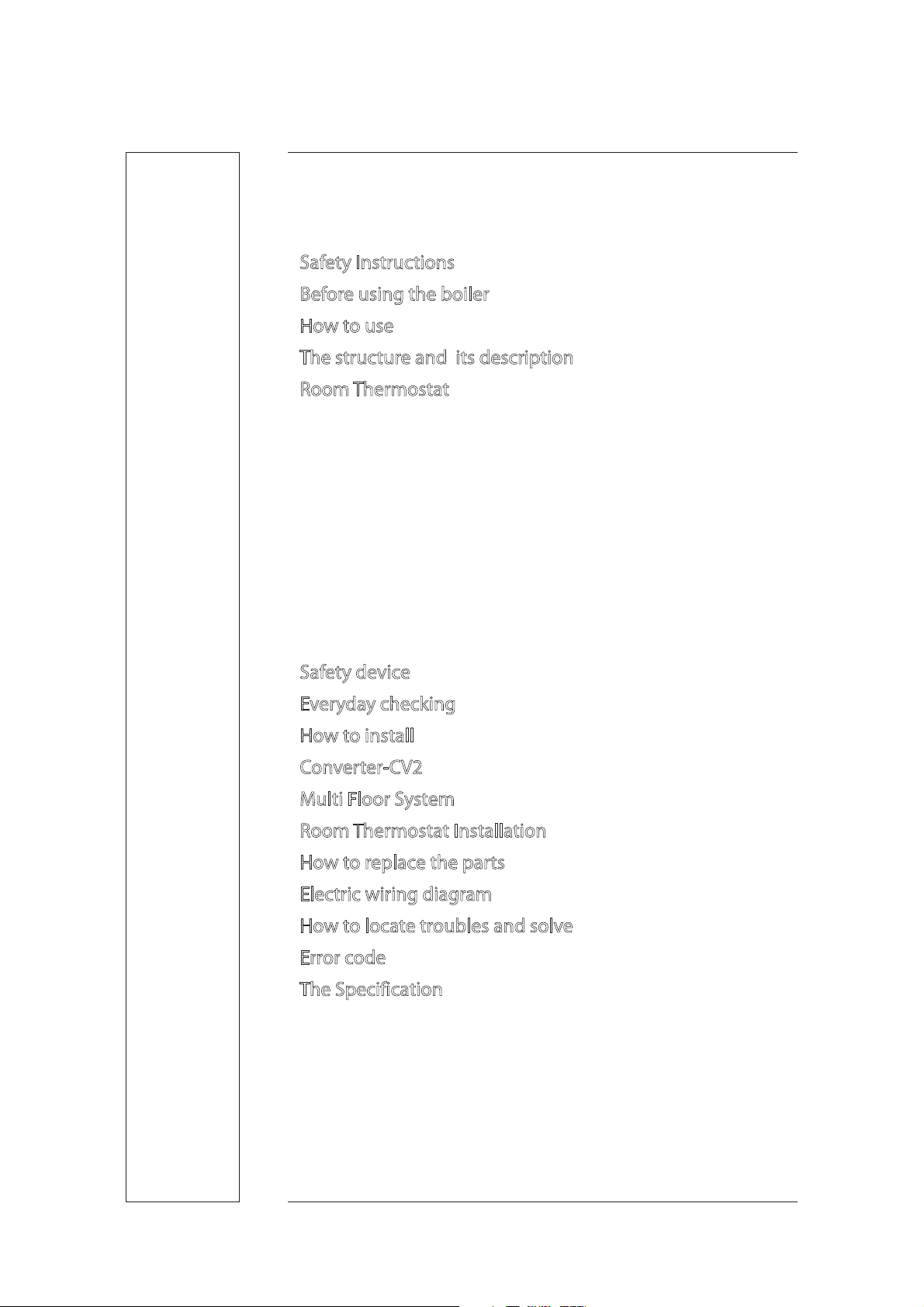
This is safety alert symbol. It is used to alert you to potential
personal injury hazards.
Obey all safety messages that follow this symbol to avoid
possible injury or death.
Indicates an imminently hazardous situation which,
if not avoided, could result in severs injury or death.
DANGER
Indicates a potentially hazardous situation which,
if not avoided, could result severe injury or death.
WARNING
Indicates an imminently hazardous situation which,
if not avoided, could result in minor moderate injury.
CAUTION
Meaning of symbols
in the guide for use
Make ground
Dismantling
arbitrarily is forbidden
Use of fire
forbidden
Dangerous
electric current
Touching is
forbidden
Page 5
Before using the boiler
5
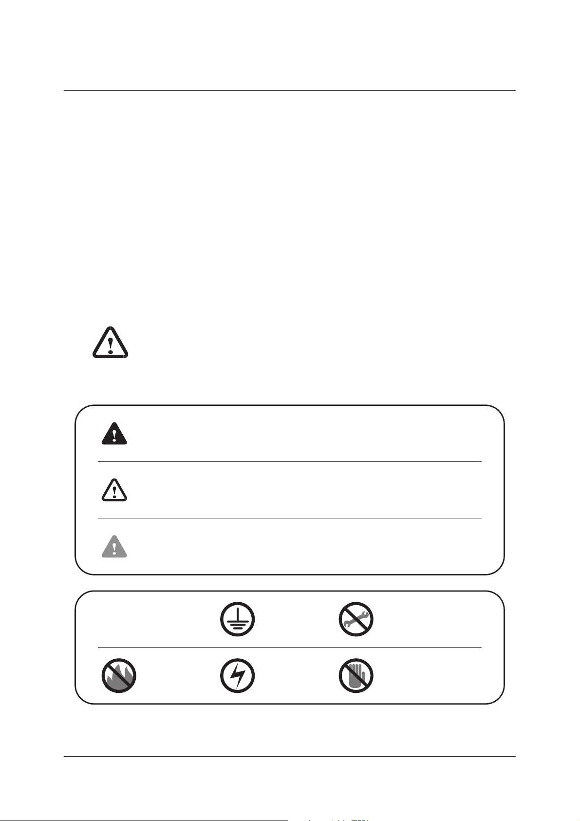
Checking points before starting up
It is essential to use only kerosen or light oil.
(Don’t use gasoline, alcohol)
It is better to use kerosene when the temperature
goes down below -5ఁ
In winter, don’t use the light-oil for summer.
Store in the Place where there is no eect
of oil, re, rain, and keep out of the sun.
Pay attention that water or dust may not
get in on time of feeding oil.
(Water or dust may cause the combustion
failure or shorten the boiler span.)
Wipe o the oil spilled.
Close the lid of the oil inlet without fail.
Feed oil after turning the power o and
locking the tank valve.
Check out if or not oil leaks in the
connecting part of the oil pipe.
Fuel
Page 6
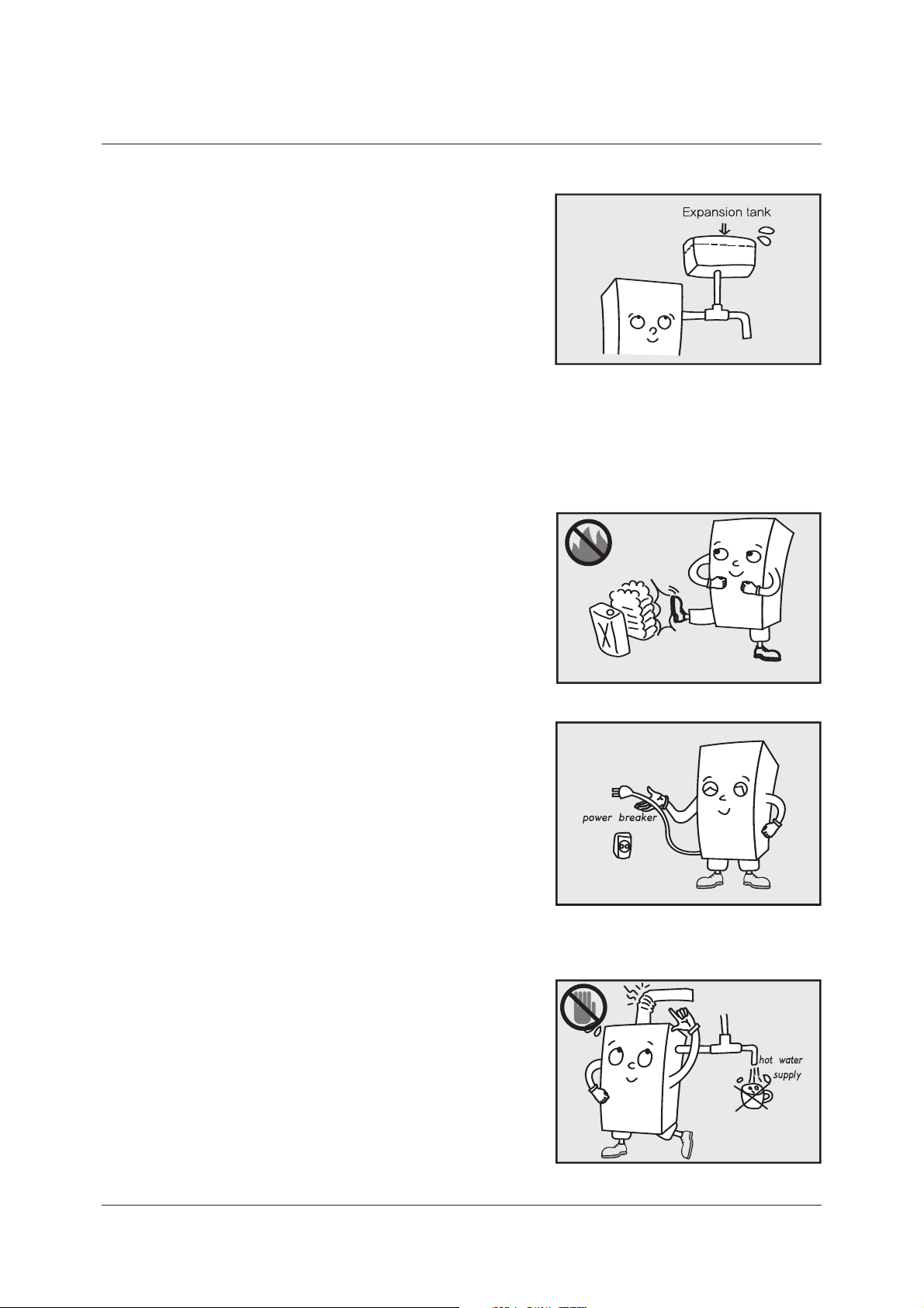
Check out that there is enough water in
the body of the boiler without failure.
Expansion tank type-Check out if there is
water in the Expansion tank, and in case
that there is no water, please ll water in
the body of the boiler.
Open Expansion Tank type-check out if
there is water in the expansion tank, and in
case that there is on water, press the power
button. Then, ‘Low Water Level’ lamp turns on
and water is supplied automatically.
Notes when using
Put the surroundings of the boiler in order
and don’t put the ammables near the boiler.
Check out whether the ignition and
the combustion is normal.(Checking through
the ame inspection window.)
When the boiler is going to be not in use for
a long time, cut o the power.(Don’t pull out
the power cord when there is a danger of freezing.)
If you pull out the power plug on time of
thunder and lightening, you can prevent the
damage on the boiler by the falling of the
thunderbolts.
Be careful not to get burned due to the
high temperature of the exhaust/inhale pipe
(exhaust pipe).
In case of emergency such as you may feel
the abnormality of the boiler, cut o the
power.
Don’t use the hot water for food.
6
Page 7
How to use
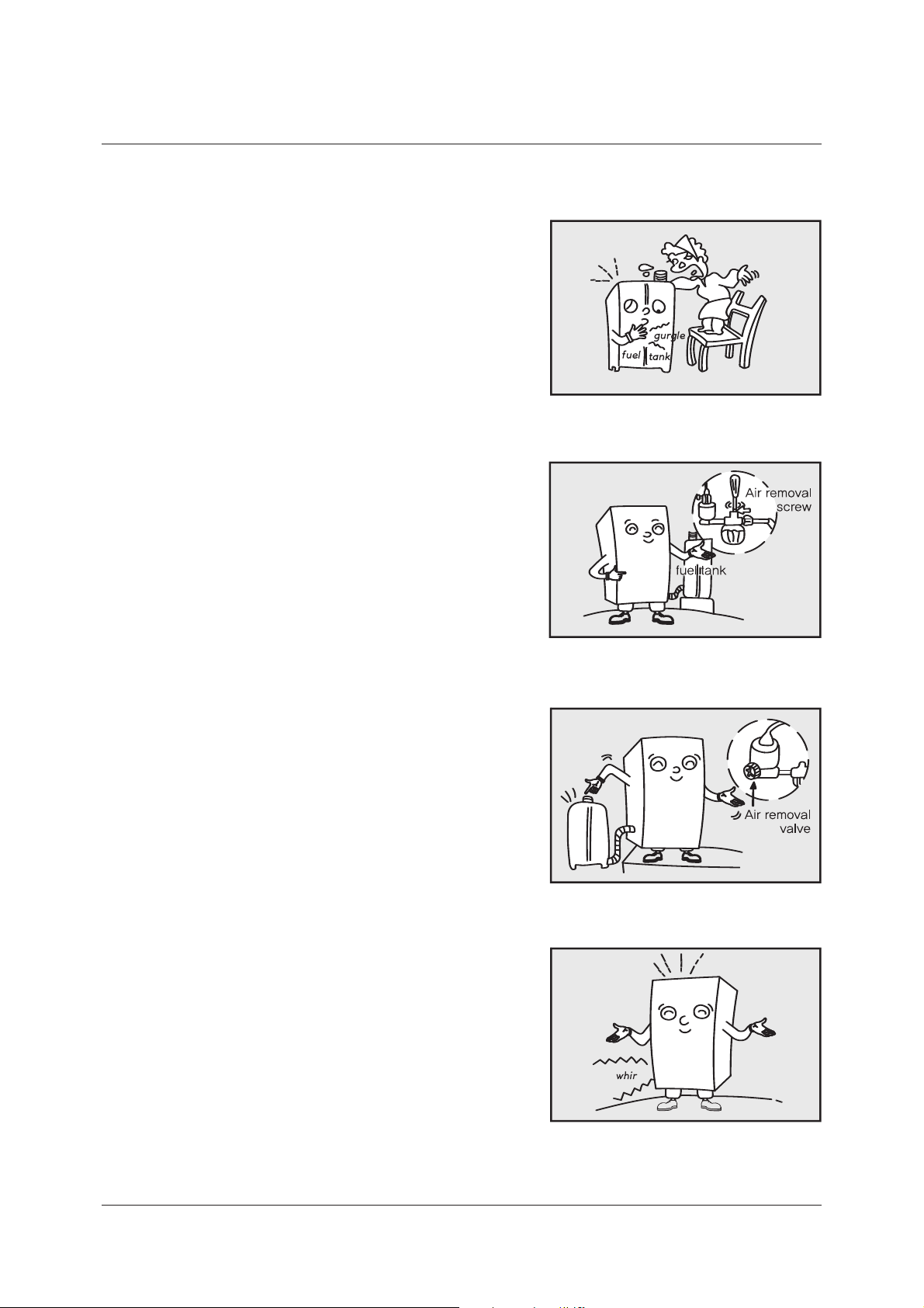
How to exhaust
Be careful that the oil tank may not run out
of oil completely.
In that case, even though oil is supplied,
air may get in. As a result, ignition failure or
operation failure may occurs.
Untighten the screw for exhaust in the oil
lter by a screwdriver, the air goes out.
When oil ows out, please tighten it.
(This is possible only in case that the oil
tank is above the oil lter.)
If the oil tank is below the oil lter or the air
ows out enough like the above, lock the
screw for exhaust and remove the air with
the exhaust valve.
In such case, open the exhaust valve turn
the power on to operate the boiler.
After about 6-7 Seconds, the electronic
pump exhaust the air o with noise,
and “CHECK” lamp on, the boiler stops.
7
Page 8
Preparation and checking before starting to operate
Now press the power button on the panel
repeatedly, and the oil ows out.
Lock the valve and press the power button
again, and the boiler gets ignited.
In case that after removing air completely,
the igni-tion has failed repeatedly about
three times, contact the sales agency or the
commercial agency.
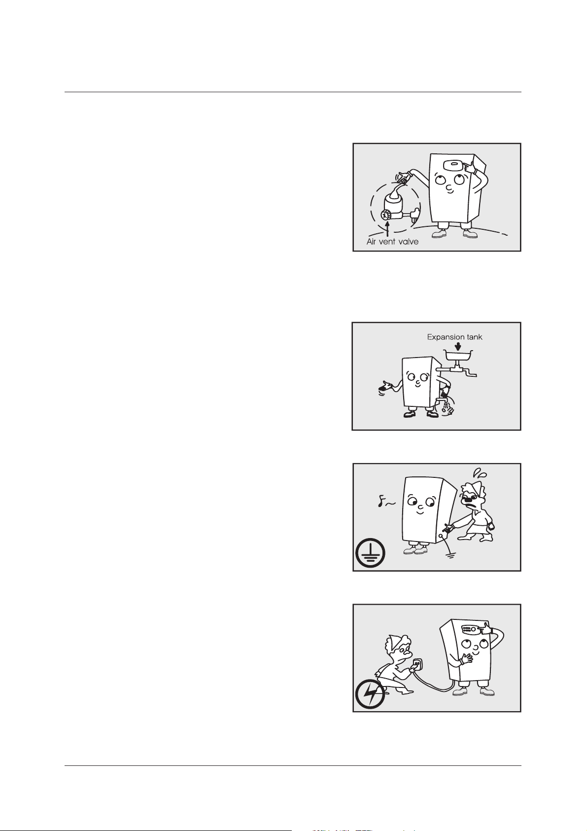
Open the drain valve, and check out whether
there is water in.
Check out whether the pipes is lled with water.
Check out that the boiler is grounded to
earth. (Don’t ground to the gas pipe or
a lightening conductor)
Plug the power plug in the outlet.
(Checking if the outlet power is 220V)
Press the power button, and check out if
“RUN” lamp turns on a little later.
8
Page 9
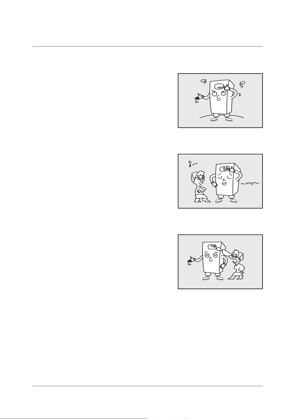
How to use
Open the window door of the Operation and
Display Panel and set the thermostat to the
position you like.
Pressing the power button starts fan motor
And the boiler gets started, turning the
“COMBUSTION” lamp on.
If ignition fails and the operation stops.
“check” lamp turns on, In this case, press the
power button on the panel.
In case that the ignition fails with pressing
the power button four or ve times, contact
the sales agency or the commercial agency.
9
Page 10
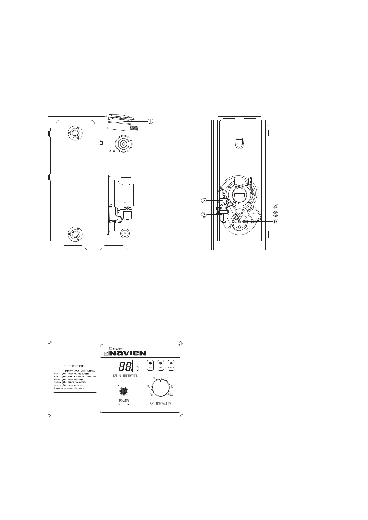
Heating temp.
LED indicate the temp.
of heating water, and
occurrence of trouble
displayed the failure code.
02. LOW WATER LEVEL
03. MISFIRE
04. PSEUDO-FLAME
05. TEMP. SENSOR FAILURE
12. MISFIRE IN COMBUSTION
16. BIMETAL OVERHEAT
The Structure of the boiler
(Model No : LST-17,21,24,30,41K / LFA-17,21,24,30,41K)
Operation and display panel (KDC-106M)
CONTROLLER
ELECTRONIC PUMP
OIL FILTER
PRE-HEATER
I.G TRANS
FLAME DETECTOR
(C.D.S)
The structure and its description
10
Page 11
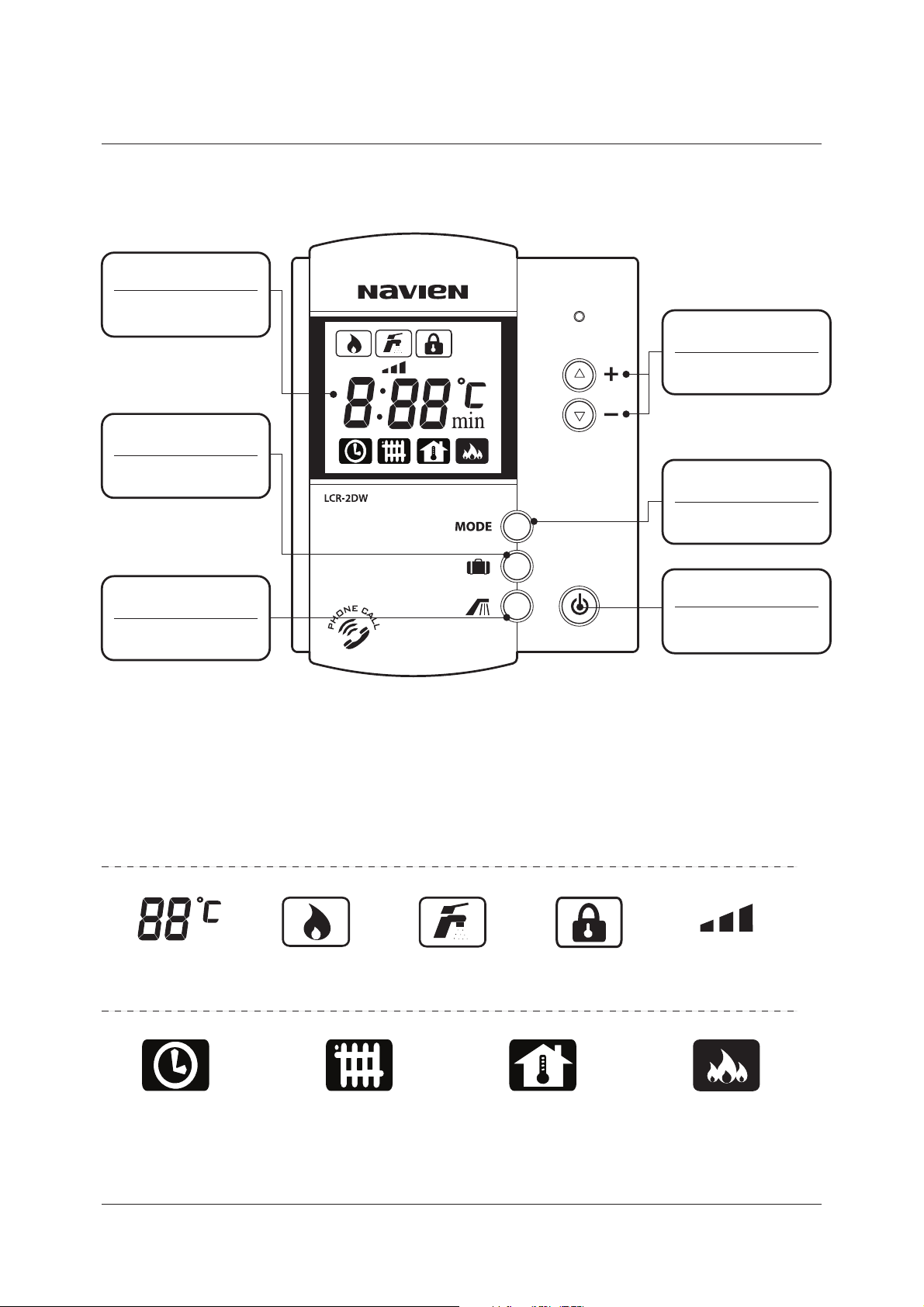
LCD
Indicating each
function and status
LCD Display
Room Thermostat
Power ON/OFF
Power
Outing Setting Mode
Outing Mode
Temp. & Timer Mode
UP/DOWN
Select Mode
MODE
Hot Water Mode
Hot Water
Room Thermostat (LCR-2DW)
11
Temperature
Timer
Heating
Operation
Indicator
Heating
Water Temp.
Hot water
Mode
Outing
Mode
Room Temp Power Heating
Hot Water
Temp. (3 Step)
Page 12
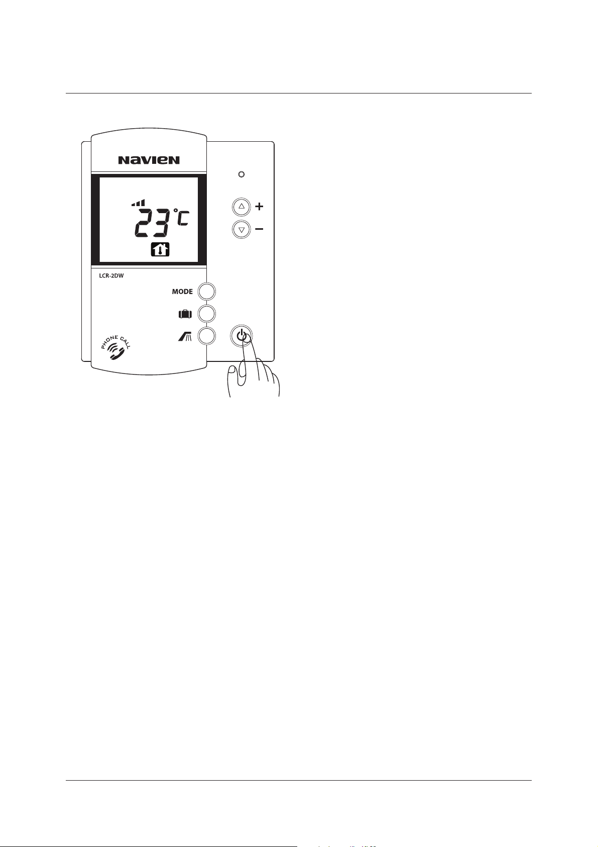
Room Thermostat On/Off
Press the power button.
LCD is on when pressing the power button.
Hot water and heating operation stops
and LCD is turned o when pressing
the power button again.
12
Page 13
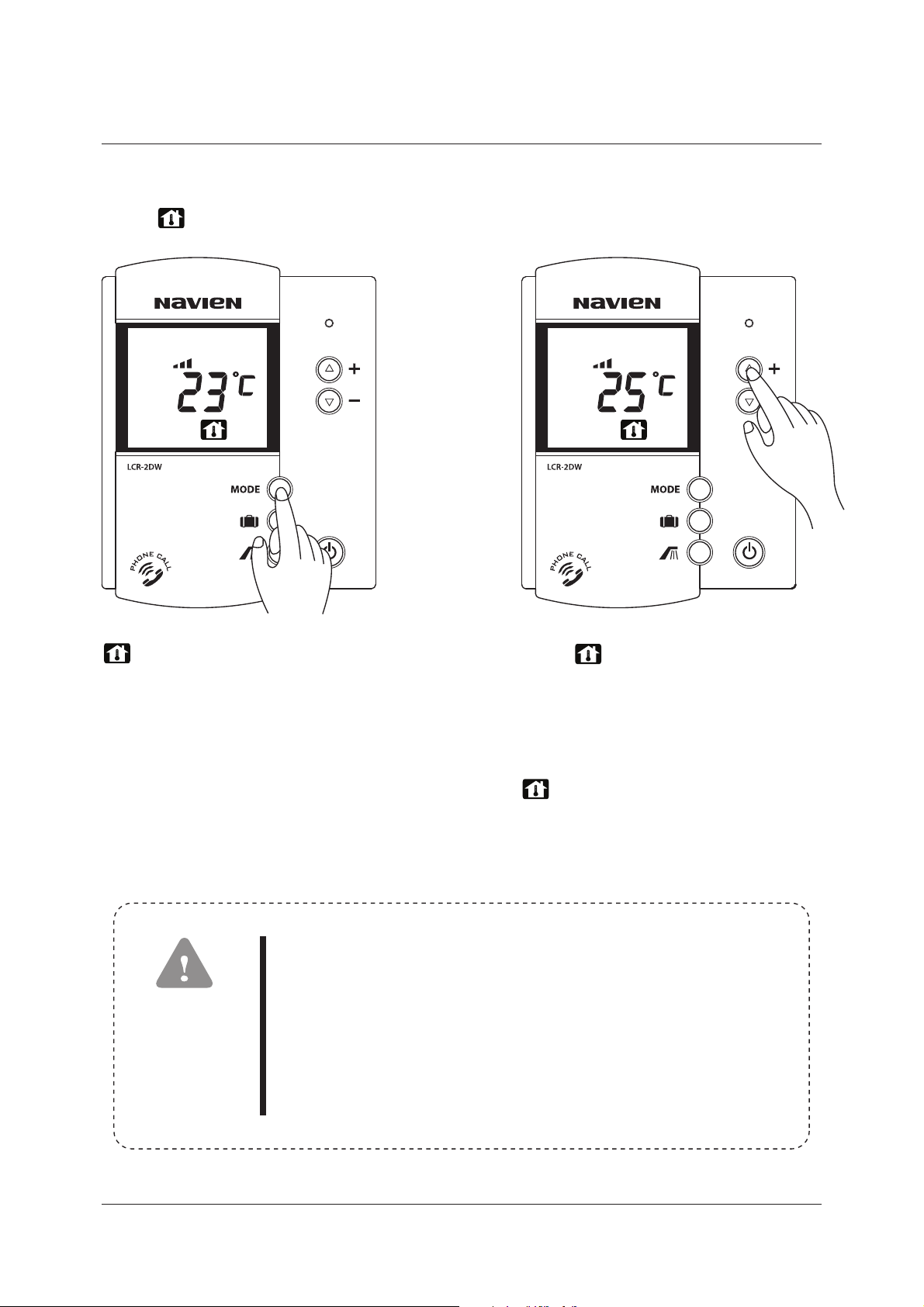
Room Temp. Mode
Press the Mode button repeatedly,
until is displayed.
Set the heating temp.
with +/- button.
blinks when selecting
Room Temp. Mode
If a room thermostat is programmed with Room Temp. Mode
and it is placed in the following places when using Room Temp.
mode, it may cause some errors to recognize temperature.
CAUTION
1. Frequently opened and closed door and drafty place.
2. A place where direct sunlight is eected and high humidity.
3. A place under direct inuence from heat, such as radiator.
When blinks, set the desired
heating temp. between 10~40丯 by
adjusting +/- button, after a while,
it is automatically saved.
Heating temp. can be set by 1丯.
After the setting is done,
is on and current room temp.
is displayed.
In that case, Heating Water Temp. is recommended.
13
Page 14
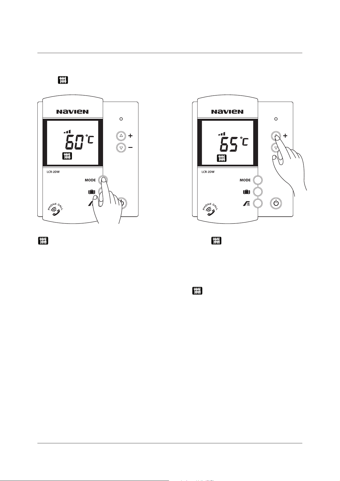
blinks when selecting
Heating Water Temp. Mode
When blinks, set the desired
heating temp. between 40~80丯 by
adjusting +/- button, after a while,
it is automatically saved.
Heating temp. can be set by 1丯
After the setting is done,
is on and current heating water
temp. is displayed.
Press the Mode button repeatedly,
until is displayed.
Set the heating temp.
with +/- button.
Heating Water Temp. Mode
14
Page 15

Timer Mode
Timer Mode is a function that boiler repeatedly operates 20- minute stop and
again that can be set in the range of hour 0~9, 50 minutes.
Press the Mode button repeatedly,
until is displayed.
Set the heating stop time
with +/- button
blinks when selecting Timer Mode. When blinks, set the desired
heating stop time.
It can be set by 10 min., up to 50min
in the range of hour 0~9 by adjusting
+/- button, after a while, it is
automatically saved.
After the setting is done, is on
and current room temp. is displayed.
Heating stop time ‘0’ means boiler is continuously operates.
In this case, heating temperature keeps increasing.
CAUTION
so, please be careful.
15
Page 16

Press the MODE button and select the
desired heating to cancel the Outing Mode.
When selecting Power Heating, is displayed
and it is combustioning for 30 minutes continuously.
After 30 minutes, it returns to previous
heating mode.
Press the Mode button repeatedly,
until is displayed.
Power Heating Mode
Outing Mode
will be displayed and Outing Mode
will be set.
Press button
Use this function when operating the boiler with minimum capacity without
heating and there is no one at home.
16
Page 17

Setting Hot Water Temp.
Press button. Set the hot water temp.
with +/- button.
is displayed when pressing
the Hot Water button.
Please make sure the hot water temp. is not too hot or too
cold before taking a shower or bath.
CAUTION
When blinks, set the desired
hot water level among low, mid, and
high by adjusting +/- button,
after a while, it is automatically saved.
low mid high
17
Page 18

Press the MODE button and select
the desired heating to cancel the
Hot Water Mode.
will be displayed and Hot Water
Mode will be set.
Press button.
Hot Water Mode
Use this function only when hot water is needed.
1. Please be careful that infants and young children do not use
hot water without a guardian for safety.
2. When others use hot water, do not change the hot water temp.
setting for safety.
CAUTION
18
Page 19

When using outside telephone, call the phone, after the call is connected to
the boiler after ringing the preset number of times, you will hear a 'beep' sound.
Then, manipulate the buttons as described above.
TIP
CM
AM
1 2 3
4 5 6
7 8 9
*
0
#
CM
AM
1 2 3
4 5 6
7 8 9
*
0
#
With phone network, heating function of room thermostat can be set.
Activating the boiler
1. Press "#" button 3 times. 2. Hang up the phone, when hearing
'beep-beep' sound.
The boiler is operated with ‘Power Heating Mode‘ for 30 minutes and returns to
the previous mode (If the room thermostat is o, return to Outing Mode.)
Remote Operation By Telephone
*
*
*
CM
AM
1 2 3
4 5 6
7 8 9
*
0
#
*
CM
AM
1 2 3
4 5 6
7 8 9
*
0 #
#
#
#
#
Suspending the boiler
1. Press "#" button 3 times. 2. Hang up the phone, when hearing ‘
'beep-beep-beep' sound.
Then, it changed to Outing Mode
19
Page 20

CM
AM
1 2 3
4 5 6
7 8 9
*
0
#
CM
AM
1 2 3
4 5 6
7 8 9
*
0
#
CM
AM
1 2 3
4 5 6
7 8 9
*
0
#
0
0
0
0
CM
AM
1 2 3
4 5 6
7 8 9
*
0
#
When altering the number of ringing
1. Press"0" button 3 times. 2. 'beep-beep-beep-beep'
sound will be ringing 4 times.
3. Press a button you select out of
5,6,7,8,9, or 0 three times.
4. After 'beep-beep-beep-beep-beep'
sound, hang up the phone.
1. If you don't press any buttons for 10 seconds or longe after
pressing '#' or '*' button, the telephone will automatically
hang up.
2. Make sure to hang up the phone after hearing activation
or suspension signal.
3. If you don't hear the 'beep' sound while using it, manipulate
it again slowly.
CAUTION
20
Page 21

When it doesn’t light even with the power
button “ON” or it gets extinguished due to
running out of oil, the FLAME Detector(Cds)
gets to work and stops the operation
Combustion safety device
If water is insucient in the boiler, it
interrupts the operation of the boiler with
the power cut o.
When water rells, the boiler starts again
automatically.
Low water level blocking device
If the temperature of the boiler rises up too
high, it is dangerous. So, in such case, this
device cuts o the power automatically.
When the overheating preventer gets to
operated the combustion stops and “CHECK”
lamp turn on.
If the overhead temperature is fall “CHECK”
lamp turn o and “RUN” lamp turning on
automatically.
If the operation stop is repeated again, contact
the sales agency or the commercial agency.
Overheating preventer
During the hard winter, the circulation pump
or the burner operates automatically to
prevent the heating circuit from freezing.
In winter, keep on plugging in the power
cord and turning the power button “ON”.
(the insulation state of the pipes must be
normal)
Freezing preventer
If the power gets o, oil gets blocked
automatically and the combustion stops.
Safety device on power-failure
Safety device
21
Page 22

Check out whether the combustibles is near.
Keep cleaning all the time and don’t let the
dust accumulated.
Check out whether oil leaks from, is stacked
on, or soaks into the oil tank, oil pipes, the
body of the boiler, etc.
Check out whether there is any water leakage
from the body of the boiler and the pipes.
Open the drain plug of the oil tank regulaly
and remove water.
Points to be checked once or more a year
Everyday Checking
22
Page 23

Cleaning of boiler
Much soot accumulated inside the boiler
will reduce the life and eciency.
At least once a year, clean the boiler inside.
Cleaning the oil filter
In case that the oil lter gets dirty, stop
operating, lock the oil valve, and remove
dust or rust accumulated below the oil cup.
Detach the oil cup by rotating right and left.
Pull down the lter.
Wash the lter and the inside of the oil cup
with clean kerosene and light oil.
Cleaning the oil tank
Water may get mired in during feeding oil or
get accumulated naturally during the long
period in the oil tank. In this case, drain water
o through the drain plug in the oil tank,
and when oil starts to get out, lock it.
23
Page 24

Cleaning the flame detector
If the light-receiving surface(sensing surface)
gets darkened with soot, the bad sensitivity
cause the wrong automatic operation.
You can pull out the ame detector(black)
which is attached in the lower part of the
burner.
Wipe the glassy surface of the ame
detector with a scrap and x it in its position.
Checking the exhaust pipe
At least once a year,check for any loose
joints in the discharge(piping and ue),
clogging in ue, corrosion or leak. If any
abnormality is found, contact out sales
agency for checking up.(blocking pipes or
holes, and so on)
24
Page 25

For the place to install the boiler, choose the place possible to do the accompanying
works, such as water supply works or electric works.
For the place to install, choose the place conformed to the installation standards
of the boiler and the construction act of the code of each city or municipality
Install the boiler in the place as wide as possible for the maintenance and the re
prevention.
Install the boiler in the place convenient for controlling and manipulation of the
temperature.
If there is no electric outlet in the proper position, do wiring by requesting to a
company designated by the electric power company.
Around the installation place, there must be no place which stores and treats the
combustibles and the inammables.
There should be equipped drainage in the in stalling spot.
How to install
Choosing of the installation place
Open cistern tank
The diagram of the standard piping : Cistern tank install type
Never install any valve between
the boiler and cistern tank.
Supply Water
Pipe
Minimum 1.5m
Circulation Pump
Distributor
Distributor
Condensate
Outlet
Drain Drain
F.L
Install the condensate outlet hose for condensing model as above
Expansion Tank
Supply Water Pipe
Roop water
tank
Water
Water
Expansion tank
Circulation Pump
Bypass Pipe
Install the pipe as above when circulation pump
install heating water inlet
In casa of water inlet through
roof water tank
Expansion Tank
Water
Hot Water Inlet
Hot Water Outlet
Hot Water Outlet
Heating Water
Inlet
Cold Water
Hot Water
Heating Coil
Fan Coil
Radiator
Boiler Back
25
Page 26

1.
2.
3.
4.
5.
6.
7.
8.
The distributor on the return water distributor side should be placed lower than
the heating inlet.
Connection should be made by installing a safety valve with 3.5kgf/偌 or lower
opening the discharge piping to the cistern tank.
The maximum operation pressure is 3.5kgf/偌. Do not supply water at a higher
pressure or directly connect the water pipe having the pressure higher than.
Overow of water during the heating to the cistern tank means short tank
capacity. Exchange it with a larger one.
Backow of water during the running or stopping of the circulation pump to the
cistern tank is caused by too much air in the pipe. Remove air by opening valves
on the distributor one at a time, while running the circulation pump.
Evaporation at the cistern tank means failure in the system. Contact your
representative to receive the check.
Never install any valve between the boiler and the cistern tank.
We will not be liable for any defect or breakdown caused by the failure to
comply with the above precautions.
Sealed cistern tank
Precautions
Safety Valve
Air exhaust Valve
Filter
Reducing Valve
Check Valve
Circulation Pump
Distributor
Condensate
Outlet
Drain Drain
F.L
Sealed Expansion Tank
Install the condensate outlet hose for condensing model as above
Install the pipe as above when circulation pump
install heating water inlet
Bypass pipe
Circulation Pump
Filter
Reducing Valve
Check Valve
Water
Hot Water Inlet
Hot Water Outlet
Heating Water Outlet
Cold Water
Hot Water
Heating Coil
Fan Coil
Radiator
Boiler Back
26
Page 27

It is recommend that the length of ue shall be less than 3 miters and the exuosity
shall be less than 2 point.(Except for the exuosity at the end of the ue)
It is recommend that use the ue tting in the connection caliber.
Be careful not to narrow down the ue. And please, maximize the radius of exuosity
when to work.
It is recommend that keeping the ue warm by using the noninammable insulation.
Oil boiler model : LST-17, 21, 24, 30, 41K / LFA-17, 21, 24, 30, 41K
It is imperative that there are no windows
around the end of the ue within 600mm.
IF the waste gas should come into the
room, you will suer from the waste gas
poisoning.
Flue Work of Forced Exhaust(FE)
The example of a standard installation
CAUTION
hG
GG
G]WWGv}ly
]WWGv}ly ]WWGv}ly
]WWGv}ly
O|u{aP
27
Page 28

CONVERTER-CV2
28
1. Check the electric voltage before you operate the boiler.
2. Tele-room controller can be adapted to voltage DC 24-31V form the main controller
of boiler.
3. Make sure to connect the electric port properly. One is far room controller , the other is
for telephone.
Check point for safety
1. Fix the room controller on the wall of room or living room. The height is about 1.5m.
2. Fix on the properly spot to sense the room temperature.
3. Avoid to x near the heater or under the sun light, this can cause the torsion of the
case and do a harm to the electric parts inside the case.
4. Avoid to x in the place there is dirty, humid, this can do harm to the electric parts
inside the case.
Check point for fixing
1. You had better take care to prevent the metallic parts (Needle, Coin)
or in ammables (Paper, Match stick) form entering into the air vent hole of the case.
This can make a short-circuit or re.
2. Do not open the case, and treat your self.
3. Be careful the power line not to exposed in the room.
4. Keep out form the volatiles (Thinner, Benzene, Solvent…)
5. Before you polish the room controller , plug the power cord out and use a smooth cloth.
Check point for usage
Description & Function
£Run (Normal operating)
¤Hot w+ater supply
¥Heating mode
¦Boiler stop
§Check (Operating error)
¨Power on/o
Signal lamp
©7HPSHUDWXUH(UURUGLVSOD\
ª%RLOHUZDWHUWHPS
FRQWURONQRE
«3RZHU5HVHWVZLWFK
Operation & Sensor
Page 29

Telephone line
Power (Ac 220V)
Hot Water
Flow Sensor
29
1. Connect rmly the room controller wire(2 Line) form the boiler , to the room controller
port in the back of the room controller.
2. Connect rmly the KD-SP wire to the telephone port in back side of the converter-CV2
3. Fix the room controller rmly on the wall, using the converter-CV2 bracket.
4. Wiring
Fixing & Wiring
Telephone
Main
Controller
Boiler
Adaptor
L1
L2
Page 30

Multi Floor System
30
CONVERTER-CV2
Cold Water
M.F.S Converter
(KDC-5P)
DR-5P
TMR-5P
M.F.S Converter
(KDC-5P)
Fan
Valve
Radiator
Fan
Valve
Radiator
Fan
Valve
Radiator
VALVE Actuator : Erie VT2325G13A01A
AC24V 2WAY WATT6.5
DR-5P
TMR-5P
M.F.S Converter
(KDC-5P)
DR-5P
TMR-5P
3rd Fl.
2nd Fl.
1st Fl.
Power(AC220V)
Pump
KDC-104P
KDC-106M
Main Controller
water flow
detector sensor
Boiler
Roomcon Terminal No.
Page 31

Multi Floor System Room Converter
Converter –CV2
31
<KDC-5P>
VALVE
(AC24V 6VA)≥
VALVE or FAN
(ACPOWER VOLT 100VA)
AC POWER INPUT
KDC-104P, 207TP
WIRE DRAW
M.F.S ROO M CONVERTER
ROOMCON
-6P,7P
Red
6 5 4 3 2 1
11 10 78912
13
Blue
Green
White
Orange
KDC-5P (AC220V)
(10, 21)
Brown
AC250V 5A
KyungDong
161
4-Φ4.5 HOLE
149
139
46
68
45
87
50
53
Page 32

Room Thermostat Installation
1.
Fix the bracket by using bolts.
2.
Connect rmly the two wires from the boiler to the screws on the back side
of the room thermostat.
Connect rmly the two wires from the telephone code to the screws on the
3.
back side of the room thermostat.
Fix the room thermostat on the bracket.
4.
32
Bolier
Main
Controller
R/C
T P
Telephone Connections
Page 33

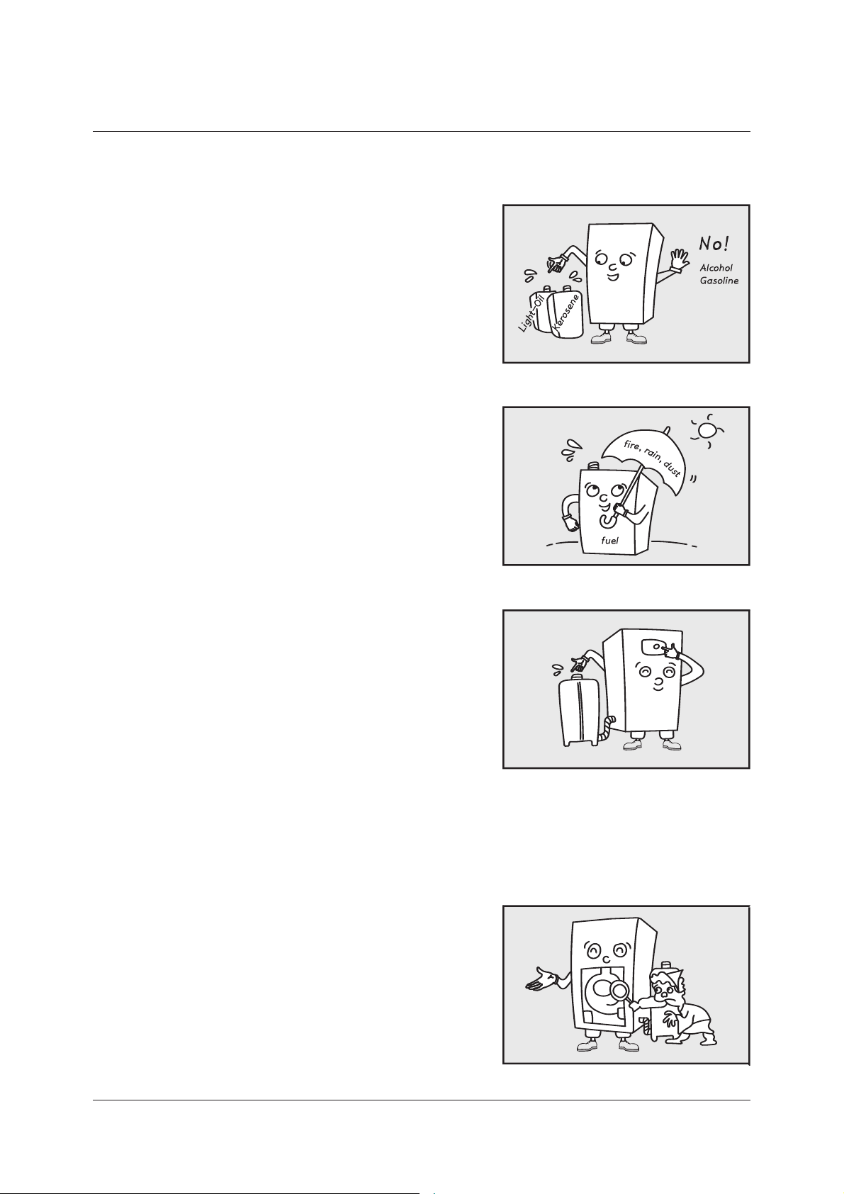
How to replace the parts
There are no parts which gets wear in a short period,
but when the replacement of the parts is needed,
consult to out sales agency or commercial agency.
For the repair of the boiler, request to our sales
agency or commercial agency, or to the A/S center.
Repairing the boiler by a man without qualication
cause another trouble, so never do that
33
Page 34

Electric wiring diagram
MODEL NO : LST-17, 21, 24, 30, 41K / LFA-17, 21, 24, 30, 41K
<#0*-&3>
34
Page 35

1. Even with pressing the
power button, the
motor doesn’t work
2. The motor rotates,
but the boiler doesn’t
ignite.
3. The boiler ignites, but
immediately stops.
4. The electronic pump
makes big noise
5. On igniting, it backres. 1.
2.
3.
The wind ow back in the
exhaust pipe.
The ignition device is bad.
Others.
Contact the sales agency or
commercial agency.
6. The abnormal noise of
the combustion
happens.
1.
2.
3.
The air for combustion is
excessive.
The amount of oil feed is
excessive.
Others.
Contact the sales agency or
commercial agency.
7. Smoke and soot occurs. 1.
2.
3.
The oil is bad or has impure
materials.
The air for combustion is
short.
Others.
1.2.The fuel pipes leaks.
The water pipes leaks.
1.2.Replace the oil.
Contact the sales agency or
commercial agency.
8. Others.
1.
2.
3.
4.
5.
The oil valve is locked.
There is no oil in the tank.
There is air in pipes.
The oil lter is locked.
Others.
1.
2.
3.
4.
5.
The oil in the oil tank is
insucient.
The ame detector(CdS),
cannot sense.
The oil lter is locked.
There is mixed impure
materials in the oil.
Others.
1.
2.
3.
The oil lter is locked.
There is air in pipes.
Others.
1.
2.
3.
4.
5.
Open the valve.
Supply oil.
Drain o air.
Clean the boiler.
Contact the sales agenct or
commercial agency,
1.
2.
3.
4.
Supply oil more.
Clean the ame detector.
Clean the oil lter.
Replace the oil with good oil.
Contact the sales agency or
commercial agency.
1.
2.
3.
Clean the oil lter.
Drain o air.
Contact the sales agency or
commercial agency.
1.
2.
3.
he temperature in the
boiler is above the set
temperature.
The room controller is o.
Others.
1.
2.
3.
This is not a trouble.
When the temperature of the
boiler goes down, get restarted.
Set the room controller to the
operation condition.
Contact the sales agenct or
commercial agency.
※Please contact your local shop and distributor for other unclean matters.
Happening Cause Solution methods
How to locate troubles and solve
Contact the sales agency or
commercial agency.
35
Page 36

Error Code
When an error occurs, the LCD shows one of the following numeric error codes
with letter 'E'.
Error Code Error Code
01
02
03
04
05
06
09
10
Heating sensor wire
Cause Cause
Overheat
Low water level
Ignition failure or
overheated unit
Pseudo ame
disconnected
Short circuit of
heating sensor
Fan RPM failure
Air pressure failure
13
14
15
16
17
27
28
29
Heating water ow
S/W failure
Gas alarm (optional)
MICOM failure
Bimetal overheat
(Mechanical)
DIP S/W setting error
Air pressure sensor error
Pipe leaking
Thee-way valve error
11
12
Water level detection
failure
Flame failure during
combustion
51
52
Black out
compensation error
Operation button
error
36
Page 37

The specification
STANDARD OIL BOILER
ITEM
UNIT
HEAT OUTPUT
HOT WATER OUTPUT
FOR USE
FUEL
ROOM SIZE
MAXIMUM WORKING
PRESSURE
HEAT TRANSFERING SIZE
FUEL CONSUMPTION
TYPE OF AIR / EXHAUST GAS
HEATING EFFICIENCY
MODEL
G
˶I
FE(%)
FF(%)
LST - 17K
16 20 25 30 40
16 20 25 30 40
Less than 96 Less than 119 Less than 135 Less than 172 Less than 238
1.90 2.43 2.84
LST - 21K LST - 24K LST - 30K LST - 41K
HEATING AND HOT WATER
Heating Oil(Light Oil)
3.5
(343)
0.84
FE (FF)
90
90
0.92 1.08
3.47 4.60
HOT WATER EFFICIENCY
ELECTRICITY
CONSUMPTION
COMBUSTION
POWER
WATER STORAGE CAPACITY
EXTERNAL SIZE
WEIGHT
HEATING
CONNECTION
PIPING
HOT WATER
CONNECTION
DIAMETER OF FLUE
FE(%)
FF(%)
W
V, Hz
˶
WÝLÝH
mm
A
A
Φ
107 117
18
327×543×777
36.5
90
90
120
220V, 50Hz
25 32
15
EXHAUST : 75
131 177
20 25
370×543×
836
42.0 52.0
370×673×
858
The specication in this operating manual can be changed for improvement without prior notice.
※
37
Page 38

38
※
The specication in this operating manual can be changed for improvement without prior notice.
The specification
STANDARD OIL BOILER
MODEL
LFA - 17K
HEATING AND HOT WATER
Heating Oil(Light Oil)
Less than 96 Less than 119 Less than 135 Less than 172 Less than 238
1.0
(98)
0.84
21.5 2.42 2.72
FE (FF)
88
88
88
88
88
88
88
88
88
88
88
88
88
88
88
88
88
88
88
88
105 110
20.5
˶
18
327×543×777
52
25 32
15
EXHAUST : 75
90
401×673×858
40
126
220V, 50Hz
133 179
3.40 4.51
0.92 1.08
18.3 20.0 23.0 29.0 38.0
18.3 20.0 23.0 29.0 38.0
LFA - 21K LFA - 24K LFA - 30K LFA - 41K
UNIT
ITEM
HEAT OUTPUT
Φ
FE(%)
FF(%)
FE(%)
FF(%)
W
V, Hz
WÝLÝH
mm
A
A
˶I
G
HOT WATER OUTPUT
FOR USE
FUEL
ROOM SIZE
MAXIMUM WORKING
PRESSURE
HEAT TRANSFERING SIZE
FUEL CONSUMPTION
TYPE OF AIR / EXHAUST GAS
HEATING EFFICIENCY
HOT WATER EFFICIENCY
ELECTRICITY
CONSUMPTION
COMBUSTION
POWER
WATER STORAGE CAPACITY
EXTERNAL SIZE
WEIGHT
PIPING
HEATING
CONNECTION
HOT WATER
CONNECTION
DIAMETER OF FLUE
Page 39

memo
39
Page 40

40
memo
Page 41

memo
41
Page 42

42
memo
Page 43

Page 44

 Loading...