


KDB-GOM
Series
- 1 -
1. Specifications of the KDB-GOM series
1.1 Kyungdong Boiler Product Features and Functions
1.2 Specifications
2. Operating Types/Constructions/Schematic Diagram
2.1 Operating Types
2.2 Constructions of the Boiler
2.3 Schematic Diagram of Operating
3. Equipment Protection and Personal Safety
4. Specifications and Functions of the Major Components
4.1 Main Heat Exchanger
4.2 Fan Assembly
4.3 Circulation Pump
4.4 Modulating Gas Control Valve
4.5 3-Way Valve
4.6 Expansion Tank
4.7 Air Pressure Switch
4.8 Hot Water Flow Sensor
4.9 High Limit Sensor(Bimetal Type)
4.10 High Limit Fuse(Fuse Type)
4.11 Heating Temperature Sensor
4.12 Ignition Transformer
4.13 Power Transformer
4.14 Domestic Hot Water Heat Exchanger
4.15 Burner Assembly
4.16 Nozzle Holder Assembly
4.17 Wiring Diagram
4.18 Main Controller
I.
Technical Information

KDB-GOM
Series
- 2 -
THE KDB -GOM
THE KDB -GOMTHE KDB -GOM
THE KDB -GOM
KYUNGDONG BOILER’S VARIABLE-CAPACITY-MULTI-PURPOSE
82%+ HYDRONIC HEATING SYSTEM
How does it work?
The KDB-GOM provides 2 different heating functions that operate independently from the same boiler. One mode
provides space heating water to heat the home. The other mode provides a continuous circuit of hot water for domestic
use eg, bath, laundry, etc. Both circuits are separate and operate at different temperature ranges.
The space-heating water is controlled by the FR-5 thermostat. A special thermostat has been provided that enables the
user to either set the room temperature required of set the heating water temperature. In some cases this thermostat may
not be suitable for multi-system applications. (The installing contractor will make this determination and install suitable
alternative controls.
The domestic hot-water is controlled by the user. Because the KDB-GOM is a multi-purpose design, it can provide hot
water on demand, there is no storage tank to hold hot water, when there is no use for it. The KDB-GOM will only produce
hot water when you use it : instantaneous. The modulating gas burner allows water to heat up as evenly as it is being
used. The KDB-GOM will continue to heat the water until the source or sources are shut off. This on-demand-use also
helps to prevent water being held in the boiler for long periods of time.
IMPORTANT:
A thermostatic mixing valve should be installed on the domestic water supply pipe to control the supply water
temperature and prevent any possibility of scalding.
Domestic hot water priority
The GOM prioritizes bath water over space-heating water and will immediately stop producing space-heating water the
moment a hot water valve is opened anywhere in the home. Once the valve has been turned off, the boiler will return to
the home-heating function again.
The seal-combustion process
The KDB-GOM is designed with a special sealed-combustion venting process. Both sides of the combustion process
(inlet oxygen and outlet carbon monoxide) are isolated from each other and are totally sealed-off from the air supply within
the home. This reduces drafts, caused by infiltration, by as much as 82% making the KDB-GOM one of the safest, most
comfortable and clean-burning boilers in the world.
1. Specifications of the KDB-GOM series
1. 1 KyungDong GOM Product Features and Functions
A. Continuous Hot Water
Its On Demand! KyungDong Boiler makes running-out-of-hot-water obsolete.
B. Everything Built-in
Installs in half the time. We tried to think of all the parts and accessories you’ll need (plus a few you might have
forgotten) and built them into this multi-purpose hydronic heating system. You’ll spend less time driving to all the supply
houses.

KDB-GOM
Series
- 3 -
C. Baked-in Beauty
The high quality porcelain finish is bake on and keeps the exterior looking new and lustrous for years to come.
D. System Timer
Save energy during times the home is unoccupied. Just set and activate the timer and leave. The unit turns off for
pre-programmed intervals until you return.
E. Room Thermostat FR-5
Convenient and accurate, large digital display is easier to read, easier to use. Our new room thermostat gives the
consumer digital control over several heating function.
F. Performance Indicator
With the use of the FR-5 electronic room thermostat, the (LED) will conveniently display the current operating
condition of the unit such as temperature of heating water, room temperature, normal operation, etc.
G. Continuous-Discharge Ignition(C.D.I.)
Direct ignition design requires no wasteful pilot burner and offers fuel savings.
H. Combustion Safety Protection
If the unit fails to ignite after the “ON” switch is pressed, or if the flame is extinguished due to a gas shortage, the
flame sensor will shut down the unit.
I. Always Balanced Operation
Despite fluctuating wind conditions, changes in atmospheric pressure and other external disturbances, the
variable-speed combustion blower provides steady performance.
J. Exhaust Safety Protection
While operating, the exhaust-discharge fan is continuously monitored. The units will be immediately stopped to
prevent fumes from entering the home if the wind gusts become excessive or if the flue exhaust has been clogged.
K. Smart Re-Start
Should the unit’s flame fail due to strong winds or temporary low gas pressure, the unit will automatically restart. In
cold weather climates, manual resets could cause freeze damage.
L. Safety Protection during Power Outages
When the power fails, the gas is automatically shut down and the units are stopped.
M. Automatic Fill & Refill
If for any reason the water level in the system drops to an unsafe level, makeup water will automatically fill to the
appropriate levels.
N. Automatic Air Bleed
Each unit has 2 built-in air bleed devices. One is manual and used for quick fill and venting convenience; the other
is air-activated and operates and automatically.
O. Removal of Impurities
Each unit come equipped with a built-in, clearable, heavy duty, particulate water filter for trapping impurities and
preventing the clogging of pipes. This is a maintenance item.
P. Air-Ratio Controller
Air ratio is monitored, adjusted and controlled prior to and during each operating cycle and will automatically adjust
the combustion rate. The air-ratio controller guarding against unsafe operating conditions also senses excessive
gusts of wind filling the flue system.
Q. Proportional Temperature Control
This control is designed to continually analyze water flow and usage while maintaining the outgoing water at a
constant, even temperature.
KDB-GOM
Series
- 4 -
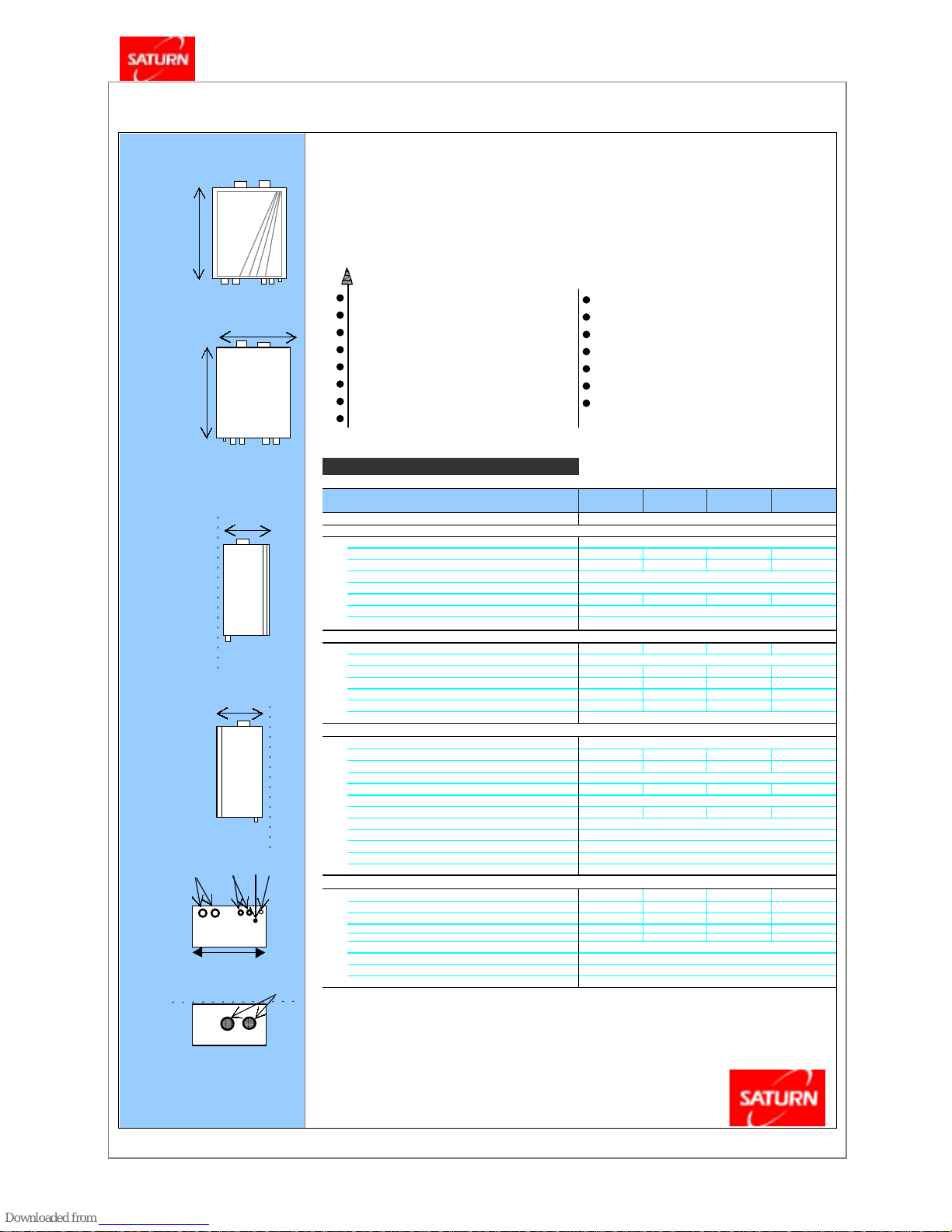
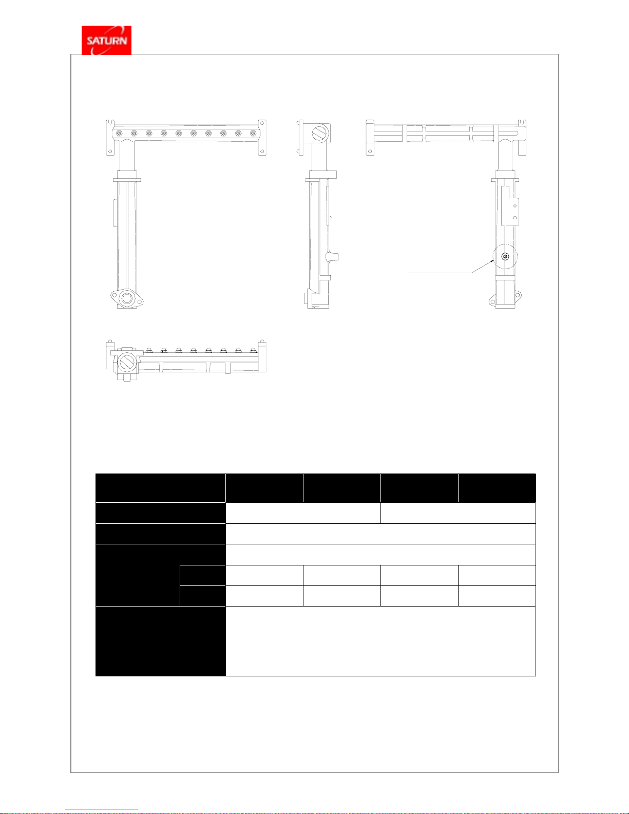
1.2 Specifications
GAS WALL-MOUNT
FRONT
View
A
Full, Dual Function Heating Design.
Natural and Propane Gas M odels.
B
Pow er-Vent, 2-Pipe C ombustion Process.
Modulating Gas for Precis ion Tem peratures.
REA R
Built-in Circulation Pump Assembly .
View
Built-in Ex pans ion Tank. Quiet, Vibration-Free Operation.
A
Built-in Freez e Protection.
Digitally Controlled, Full-Logic T hermostat.
C
Funct ion
SIDE Vi
ew
CENTR AL HEATING WATER
(LEFT
)
Const ructi on of Heat Exchanger
Heat Output (kcal/hr)
6,400
~ 16,
000
8,000
~ 20,
000
10,000
~ 25,
000
12,000
~ 30,
000
Max.Effici ency (%) 82 82 83 84
(wall)
Temperature Setting Range (℃)
Maxim um Working Pressur e (kgf/cm2)
Pre- Charged Ex pansion Tank (l iter ) 6.5 6.5 8.5 8.5
Circulation Pump
Freeze Protection Device
DOMESTIC HOT WATER
Heat Output (kcal/hr)
6,400
~ 16,
000
8,000
~ 20,
000
10,000
~ 25,
000
12,000
~ 30,
000
Max.Temperature Setting (℃)
Conti nuous DHW product ion
△T = 25 ℃
(liter )
10.7 13.3 16.7 20.0
Conti nuous DHW product ion △T = 33 ℃ (liter )
8 10.0 12.5 15.0
Conti nuous DHW product ion △T = 40 ℃ (liter )
6.7 8.3 10.4 12.5
C
Conti nuous DHW product ion △T = 50 ℃ (liter )
5.3 6.7 8.3 10.0
SIDE Vi
ew
Maxim um Working Pressur e (kgf/cm2)
(RIGHT)
OTHER DATA
Gas Type
Gas Consumption - LP (kg/hr)
1.58
1.98 2.48 2.97
(wall ) Gas Consumption (natural gas) (kcal/hr ) 19,000 23,700 29,700 35,600
Gas Inlet Supply Pressur e (natural: kPa) ( min - max)
Manifold Pressure (kPa) 0.16 ~ 0.92 0.16 ~ 0.96 0.25 ~ 0.94 0.14 ~ 0.96
Usage ( Heating & H ot Water )
Water Storage Capacity (liter) 0.7 0.7 0.8 0.8
Power (volts/cycle)
Power Consumption (watts)
Ignition
NOx Emi ssions
(Ref:0%, O2 in flue gas natural gas, ppm)
E F G D
Temp. of Exhaust Gas (℃)
WEIGHT AN D DIMENSIONS
Net Weight (l bs) 31 31 39 39
BOTTOM
A Physi cal Dimensions: Hei ght (mm) 630.0 630.0 685.0 685.0
View
B Wi dth (mm) 485 485 525 525
C Depth (mm) 235 235 250 250
D C onnection: Gas Inlet 15A, 1/2" 15A, 1/2" 20A, 3/4" 20A, 3/4"
E C onnection: Heating Water Supply/Return
B
F C onnection: Domestic H ot Water Supply/Return
(front) G C onnection: Primary Power (AC220V-50Hz)
H F lue Diameter (Intake / Exhaust) (mm)
TOP
H
Specif ication s s ubject to c hange with out prior not if ication
View ( wall )
- 2865 PELLISSIER PLACE - W HITTIER, CA 90601 - (562) 463-0880
15A, 1/2"
15A, 1/2"
70 / 75
28 (l ess than)
150 (l ess than)
20A, 3/4"
Dual
AC 220V- 50Hz
120 ~ 160
ELECT RONIC
80
17.5
Liquefied Petroleum ( L.P.) or Natural Gas
0.98 ~ 2.45
40 ~ 80
3
Self Pr imi ng
Ther mis tor
MODEL NUMBER
Combo Boiler
Stainl ess Steel / Copper
161 GOM 201 GOM 251 GOM 301 GOM
w ith 1-Year on Parts.
KYUNGDONG BOILER SPECIFICATIONS
C on trols Bo th Water F unction s Separ ately .
On-Demand Hot Water Delivery.
Com pact, Space-sav ing Design.
Limited Warranty on Heat Exc hanger
---- KEY FEATURES
Prov ides Hi-Temp Water for Heating the Home.
Pr ov ide s Hot Wate r fo r B athing & Wa s hing.
KDB - 161 / 201 / 251 / 301 GOM
Residential Gas Hydronic Heating System
GAS FIRED, WALL-MOUNT ED, MULT I-PURPOSE, HYDRONIC HEATING SYS T EMS
MODEL RAN GE : 16, 000 ~ 30,000 kcal/hr
KDB-GOM
Series
- 5 -
2. Operating Types/Constructions/Schematic Diagram
2.1 Operating Types
Item Specification
Installation
Wall Mount Type
Flue Type
Both Use FF and FE
Usage
Both Use Heating and Domestic Water (Single Pipe, 2 Waterways)
Water Supply for
Heating
Maintain normally at a constant water pressure by pressure reducing valve
(Auto / Manual)
Control Method
Proportional Control Method by MICOM
Heat Exchanger Type
Single Dry Type (131/161/201GOM) and Single Wet Type (251/301/351GOM)
Combustion Method
Air Intake Method by Semi-Bunsen Burner
Gas Flow Control
Current Proportional Control Method by Thermistor
Heat Exchange
Method of Hot Water
y Heat Exchange Method : Indirect Heat Exchange by Secondary Heat Exchanger
y Heat Exchange Type : Plate Formed Brazing Heat Exchange
y Heat Exchange Circuit : Parallel Circuit
Ignition Method
Continuous Discharge, Direct Ignition Method
Heating
/
Domestic Water
Changeover
Heating Priority, Changeover to Domestic Water Circuit by 3-way Valve
Domestic Water Signal
Detect Flow by Flow Switch
y Motor : Condenser Type
y Casing : Engineering Plastic
Circulator Pump
y Impeller and Shaft Coupled : Magnetic Type
Expansion Tank
y Type : Expansion Tank
y Volume:6.5Liter(161/201GOM), 8.5Liter(251/301GOM)
Pressure Reducing /
Flow Limiting Control
and Water Hammering
Prevention
Control Pressure Reduction/Flow Limit and Prevent Water Hammering
by Diaphragm
KDB-GOM
Series
- 6 -
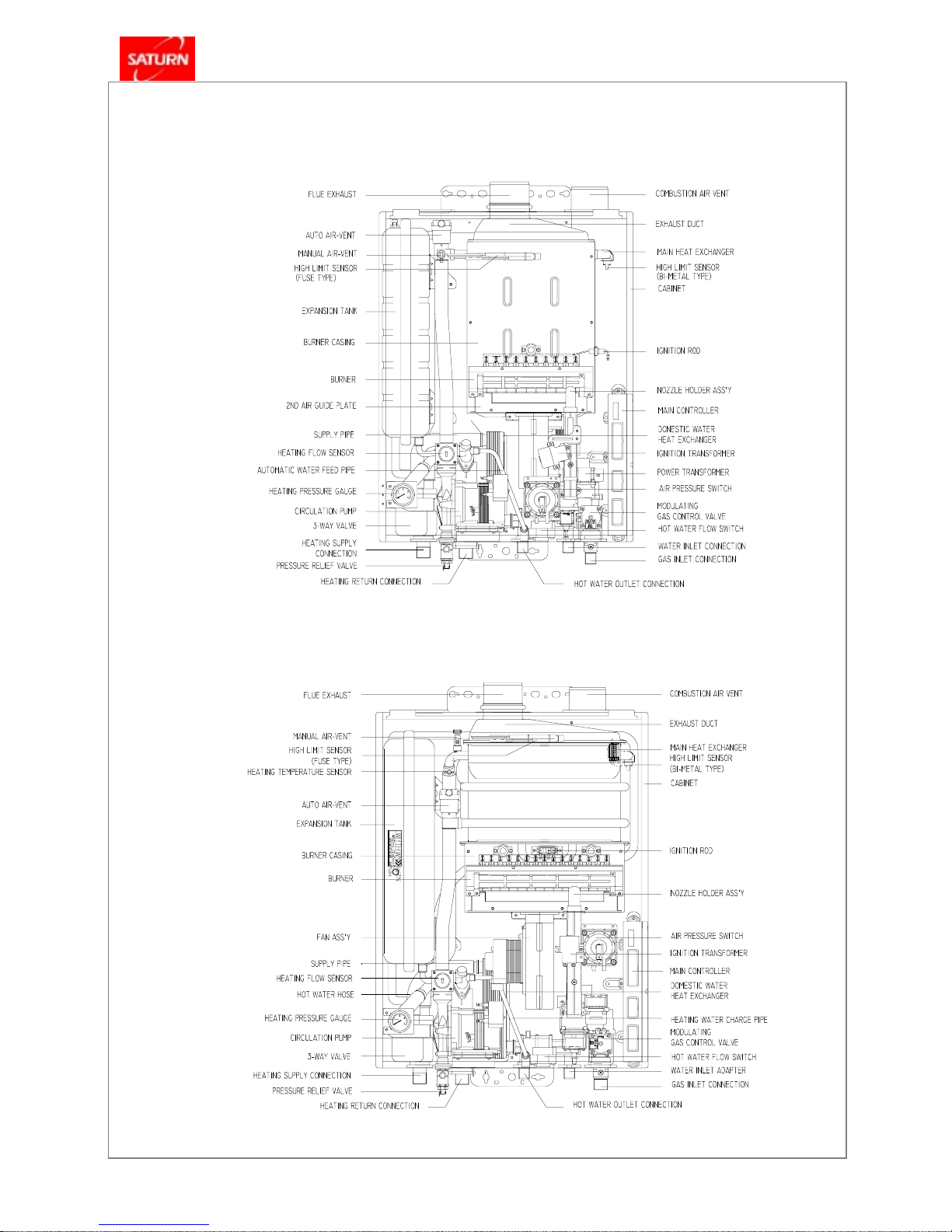
2.2 Constructions of the Boiler
■
Model : KDB
Model : KDB Model : KDB
Model : KDB – 251 / 301 GO M
251 / 301 G OM 251 / 301 G OM
251 / 301 G OM
■
Model : KDB – 161 / 201GOM
KDB-GOM
Series
- 7 -
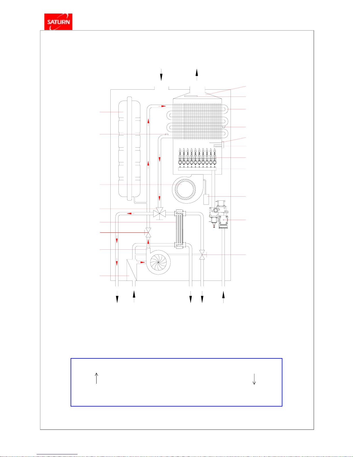
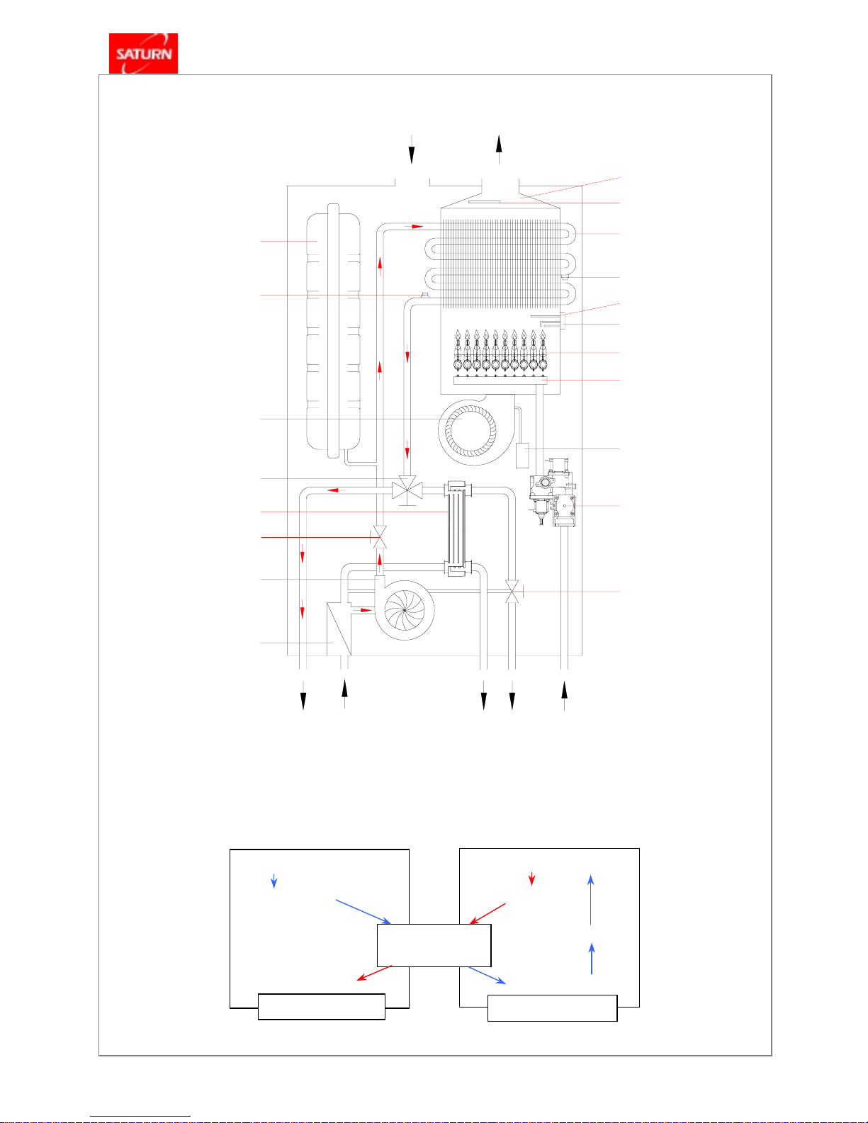
2.3 Schematic Diagram of Operating
2.3.1 Schematic Diagram at the Heating Water Supply
High Limit Fuse
Fan Assembly
Heating Temperature
Sensor
Hot Water Flow Switch
Modulating
Gas Control Valve
Expansion Tank
Air Pressure Switch
Nozzle Holder Assembly
Burner Assembly
Flame Detector
Electrode
High Limit Sensor
②
Main Heat Exchanger
Exhaust Duct
③
3-Way Valve
Gas Inlet
Domestic Water Outlet
Tap Water Inlet
⑥
Heating Return
④
Heating Supply
⑦
Heating Strainer
①
Circulator Pump
Flue Exhaust
Heating Flow Sensor
Combustion Air Inlet
Domestic Water
Heat Exchanger
①
Circulator Pump → ② Main Heat Exchanger → ③ 3-Way Valve → ④ Heating Supply
⑦
Heating Strainer → ⑥ Heating Return → ⑤ Room Heating(Heating Coil, Radiator)
KDB-GOM
Series
- 8 -
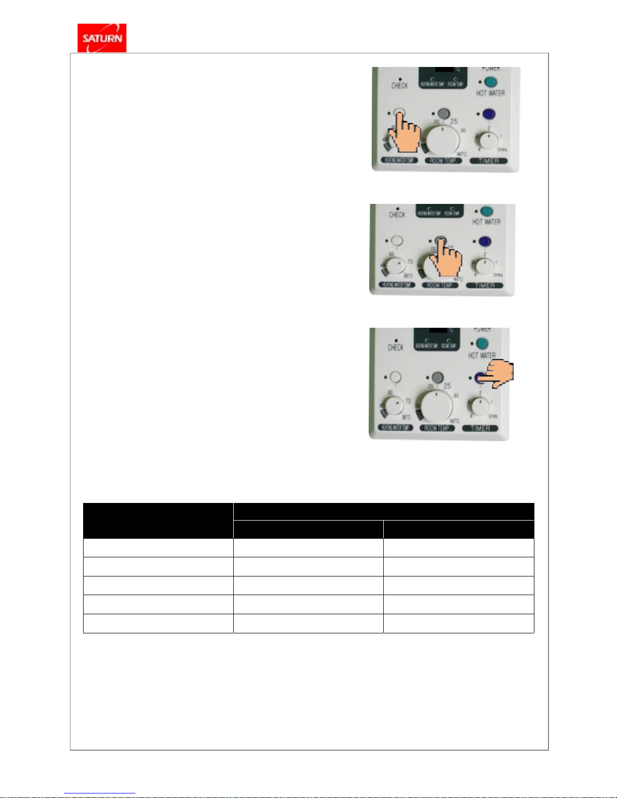
2.3.2 Controls of the Heating Temperature
2.3.2.1 When the heating water temperature is selected
- Setting Temperature: 40 ~ 80
℃
- To stop the run, turns the “HEATING WATER
TEMP.” dial to “OFF” position.
2.3.2.2 When the heating is controlled by the room
temperature
- Setting Temperature: 10 ~ 40
℃
- To stop the run, turns the “ROOM TEMP.” dial to
“OFF” position.
2.3.2.3 When the heating with the repetition time
(TIMER)
- The timer sets the stop time between 0 to 4-hours.
- Press the “TIMER” button, the boiler runs for 20minutes and stops for the time set by the timer.
- The temperature of the heating water is
automatically set at 80 ℃ and the temperature
indicator displays the room temperature.
※
If the range of control has been exceeded due to the change in the set temperature or to abrupt change in
flow, the set temperature will be reached through the proportional control with the delay of 30±3 seconds.
If 83 ℃ is exceeded, the delay of 30±3 seconds will not be performed.
Control Range
Setting Temperature,
“T” set
ON OFF
Over 78
℃
63±2.0
℃
83±2.0
℃
70 ~ 77
℃
“T” set – (14±2.0)
℃
“T” set – (6±2.0)
℃
60 ~ 69
℃
“T” set – (12±2.0)
℃
“T” set – (6±2.0)
℃
50 ~ 59
℃
“T” set – (10±2.0)
℃
“T” set – (5±2.0)
℃
Below 49
℃
“T” set – (10±2.0)
℃
“T” set – (5±2.0)
℃
KDB-GOM
Series
- 9 -
2.3.3 Schematic Diagram at the Domestic Water Supply
Fan Assembly
Heating Temperature
Sensor
②
Hot Water Flow Switch
Modulating
Gas Control Valve
ⓐ
Expansion Tank
Air Pressure Switch
Nozzle Holder Assembly
Burner Assembly
Flame Detector
Electrode
High Limit Sensor
ⓒ
Main Heat Exchanger
High Limit Fuse
Exhaust Duct
ⓓ
3-Way Valve
Gas Inlet
Domestic Water Outlet
Tap Water Inlet
Heating Return
Heating Supply
Heating Strainer
ⓑ
Circulator Pump
Flue Exhaust
Heating Flow Sensor
Combustion Air Inlet
③
Domestic Water
Heat Exchanger
③
Domestic Water
Heat Exchanger
Domestic Water Line
Heating Water Line
ⓒ
Main Heat Exchanger
④
Domestic
Water Outlet
②
Hot Water
Flow Switch
①
Tap Water Inlet
ⓓ
3-Way Valve
ⓑ
Circulator Pump
ⓐ
Expansion Tank

KDB-GOM
Series
- 10 -
2.3.4 Controls of the Domestic Water Temperature
2.3.4.1 Possible use of hot water in heating/not-at-home mode and hot water exclusive mode, according to the
flow volume detection of the hot water sensor.
2.3.4.2 Indirect control of the hot water temperature based on the heating water temperature.
2.3.4.3 Control at 80℃ when using hot water during heating.
2.3.4.4 Control at 70℃ when not-at-home or hot water exclusive mode
2.3.4.5 Stand by after hot water use
y when stopped after hot water use, the fan does not perform post purge and maintain the ON status for 90
seconds.
y the pump stops after the post purge (60 seconds)
y when using hot water again and after the hot water sensor detects the flow volume
pre-ignition Æ fuel supply Æ flame detection Æ post-ignition
y return to the before-hot-water-use status 90 seconds after the use of hot water.
2.3.4.6 Combustion in progress while in stand-by for hot water (90 seconds) or after 12 seconds of the post purge
time ( while in heating mode after the hot water sensor if “OFF”). Hot water stand-by time in progress separately.
3. Equipment Protection and Personal Safety
A. Ignition Failure
If the ignition fails, the gas supply is automatically cut off. An error code will appear as a flashing 2-digit code on the room
thermostat(models FR-5 only). The error codes are discussed in the troubleshooting section of the installation manual.
B. Flame Detection
If the fails and/or the re-ignition attempt fails, the gas supply is automatically cut off. An error code will appear on the room
thermostat(models FR-5 only).
C. Power Interruption
When the power is restored after a power failure, the boiler will automatically start and return to normal
operation(Manual reset is not required).
D. Excessive Air Pressure
Occasionally an excessive gust of wind from outside may be forced into the flue pipe. The air-ratio control module
will detect these strong back-drafts. To prevent any products of combustion from re-entering the building through the
open flue, the gas supply will be automatically cut off. An error code will appear on the room thermostat(models FR5 only).
E. Explosive Re-ignition Protection
Abrupt, noisy startups and backfires are prevented by means of soft ignition, a trademark of our air-ratio control
module.
F. Overheat Protection
Any overheating of the burners or heat exchanger will automatically shut down the supply of gas to the burners.
An error code will appear on the room thermostat(models FR-5 only).
G. Low Water-Level Safety
Water levels in the heating pipes are continuously monitored to prevent the boiler from operating if there is no
water or a restricted flow through the piping. The boiler will automatically shut down and an error code will appear
on the room thermostat(models FR-5 only).

KDB-GOM
Series
- 11 -
H. Automatic Water Fill
Should the water level in the system drop too low, a sensor will automatically activate the re-fill circuit.
I. Freeze Protection
During the heating season, a sensor inside the boiler will automatically detect and initiate safe heating cycles to prevent internal
equipment damage from occurring should freezing temperatures surround the boiler.
Note !
- When there is no gas supply
available, the circulating pump will automatically start up to guard the pipes from freezing (available only in boilers equipped with a
circulation pump).
J. Gas Pressure Control
To prevent internal damage from rupture, each boiler is protected from occasional surges in gas pressure by a regulating governor
device located in the gas valve.
K. Short-Circuit Protection
Any short-circuits occurring inside the boiler’s electrical circuit will immediately ‘blow’ the internal glass fuse(s)
and automatically cut off the gas supply.
L. Lightening Protection
Each boiler is specially grounded inside and out to protect against lightening strikes.
M. Combustion air flow control
When the combustion airflow is disrupted due to a defective, obstructed or an abnormal back-pressure of the
flue, the combustion is shut off safely.
N. Thermostat Control Failure
Should the thermostat fail to function properly, as a safeguard, the boiler’s gas supply will be automatically shut
down.
KDB-GOM
Series
- 12 -
4. Specifications and Functions of the Major Components
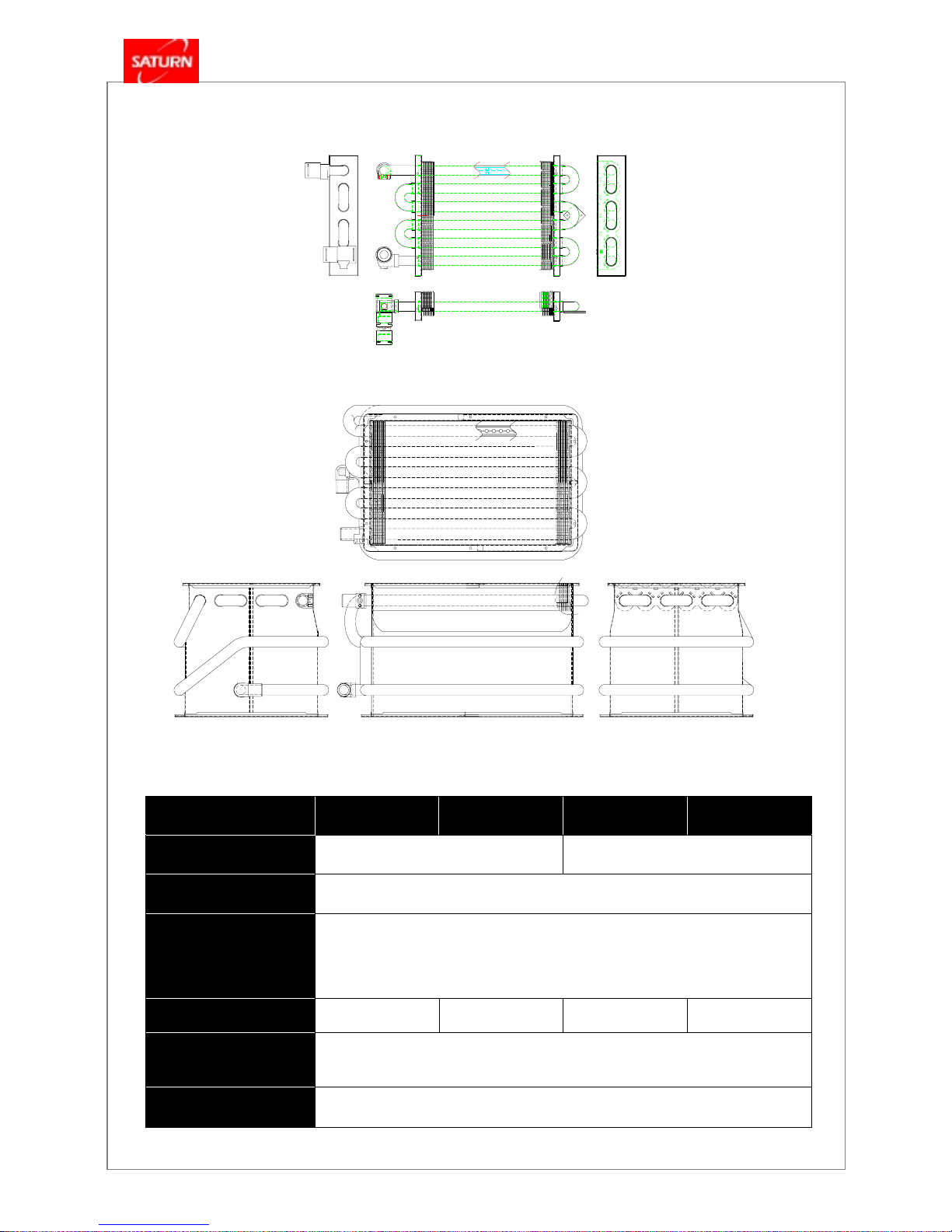
4.1 Main Heat Exchanger
Item
161GOM 201GOM 251GOM 301GOM
Typ e
Single Dry Type Single Wet Type
Structure
Copper Fin+Copper pipe Brazing
Function
- For use of heating and hot water, absorb generated heat from main burner and
then transmit it to heating pipe and hot water heat exchanger.
Number of Heat Fin
72 Fin 80 Fin 106 Fin 112 Fin
Material & Dimension
- Copper Pipe:C1220T-H(φ15.88).
- Heat Fin:C1220P-1/4H(t=0.4)
Heat Exchange Method
Instantaneous Method
KDB – 251 / 301 GOM
KDB – 161/201GOM
KDB-GOM
Series
- 13 -
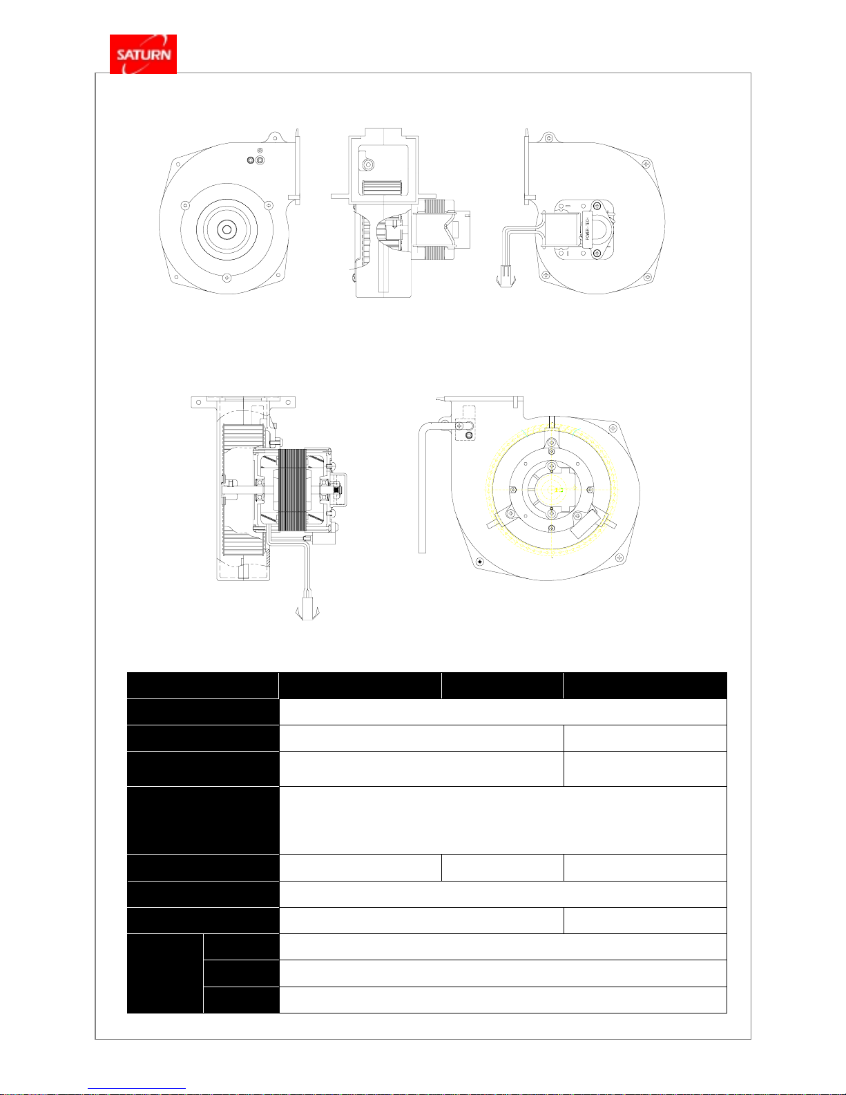
4.2 Fan Assembly
Item
161GOM 201GOM 251/301GOM
Fan Type
Phase Controlled Air Intake Fan
Motor Type
Shading Coil Induction Motor Condenser Induction Motor
Blower Dimension
(mm)
φ
100 X 40L X 45 Fin
φ
134 X 40L X 60 Fin
Function
- Supply air needed for combustion and exhaust the remained gas before and after
combustion in order to prevent explosion in advance.
Bell Mouth(mm)
φ
60
φ
70 -
Rated Voltage
AC 220V, 50Hz
Power Consumption
Max.: 36.4 W, Min.: 14.0 W Max.: 75 W, Min.: 30 W
Casing
ALDC12
Blower
AL 5052
Material
Venture
ALDC12
KDB – 161 / 201GOM
KDB – 251 / 301GOM
KDB-GOM
Series
- 14 -
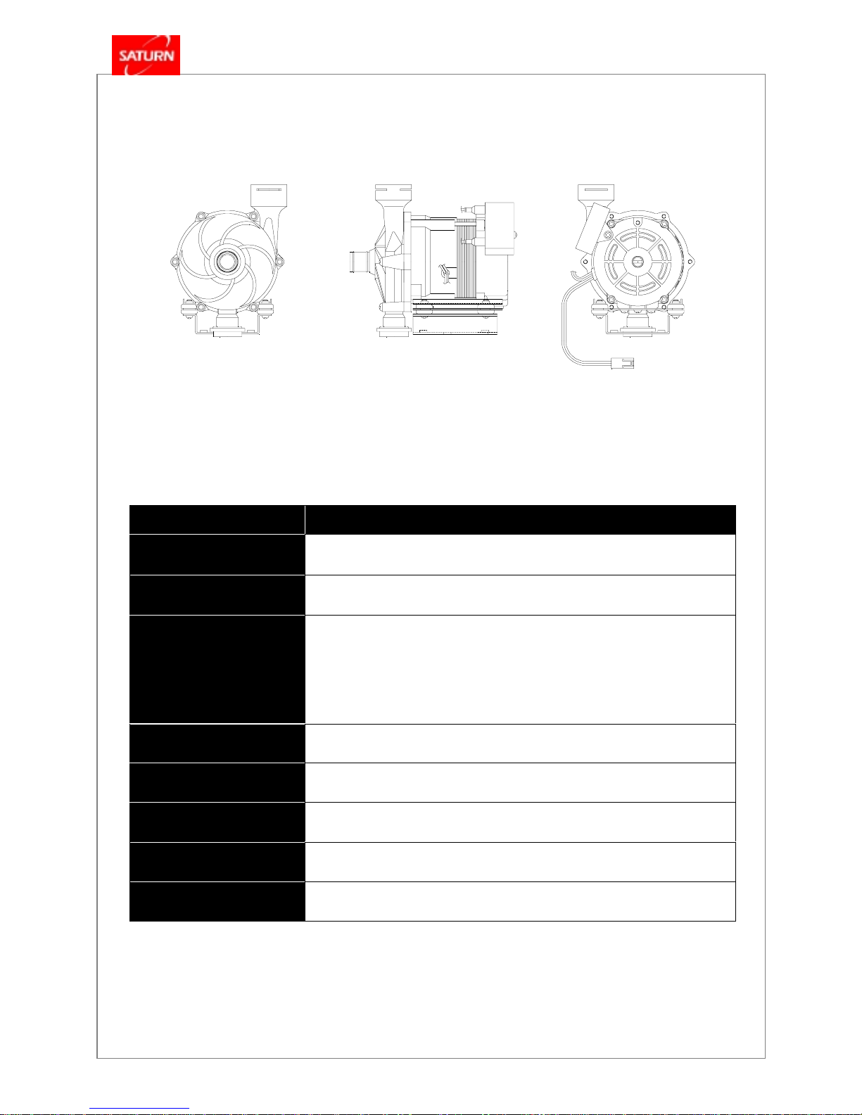
4.3 Circulation Pump
Item
All GOM models
Pump Type
Magnet Type
Motor Type
Single Phase, 2 Pole Induction Motor
Function
- Transmit the absorbed heat from main heat exchanger to heating pipe by
circulating heating water when use heating.
- Transmit the absorbed heat from main heat exchanger to hot water heat
exchanger by circulating heating water inside of boiler when use hot water.
Maximum Pump Head
10M(at 0 gal/ min )
Rated Voltage
AC 220V, 50Hz
Power Consumption
90 W
Condenser Capacity
2.5
㎌
Weight
2.45 kg
KDB-GOM
Series
- 15 -
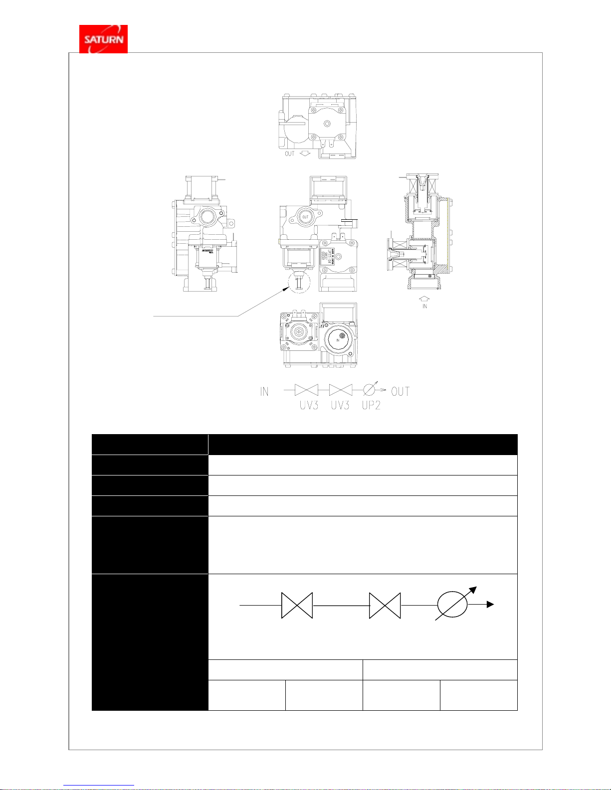
4.4 Modulating Gas Control Valve
Item
All GOM models
Model No.
UP 33 –06 (TIME CO.)
Rated Voltage
AC 220V, 50 / 60Hz
Power Consumption
8 W
Function
y Controls the flow of gas supply by the current value received from main
controller.
y Cut off the gas to prevent danger by the signal of sensor when happen troubles
caused by improper combustion.
Magnet Valve Proportional Valve
Schematic Diagram
SV1
(UV3)
SV2
(UV3)
PV
(UP2)
(SV1)
(SV2)
(PV)
Secondary pressure
Adjust Screw
Gas flow diagram
KDB-GOM
Series
- 16 -
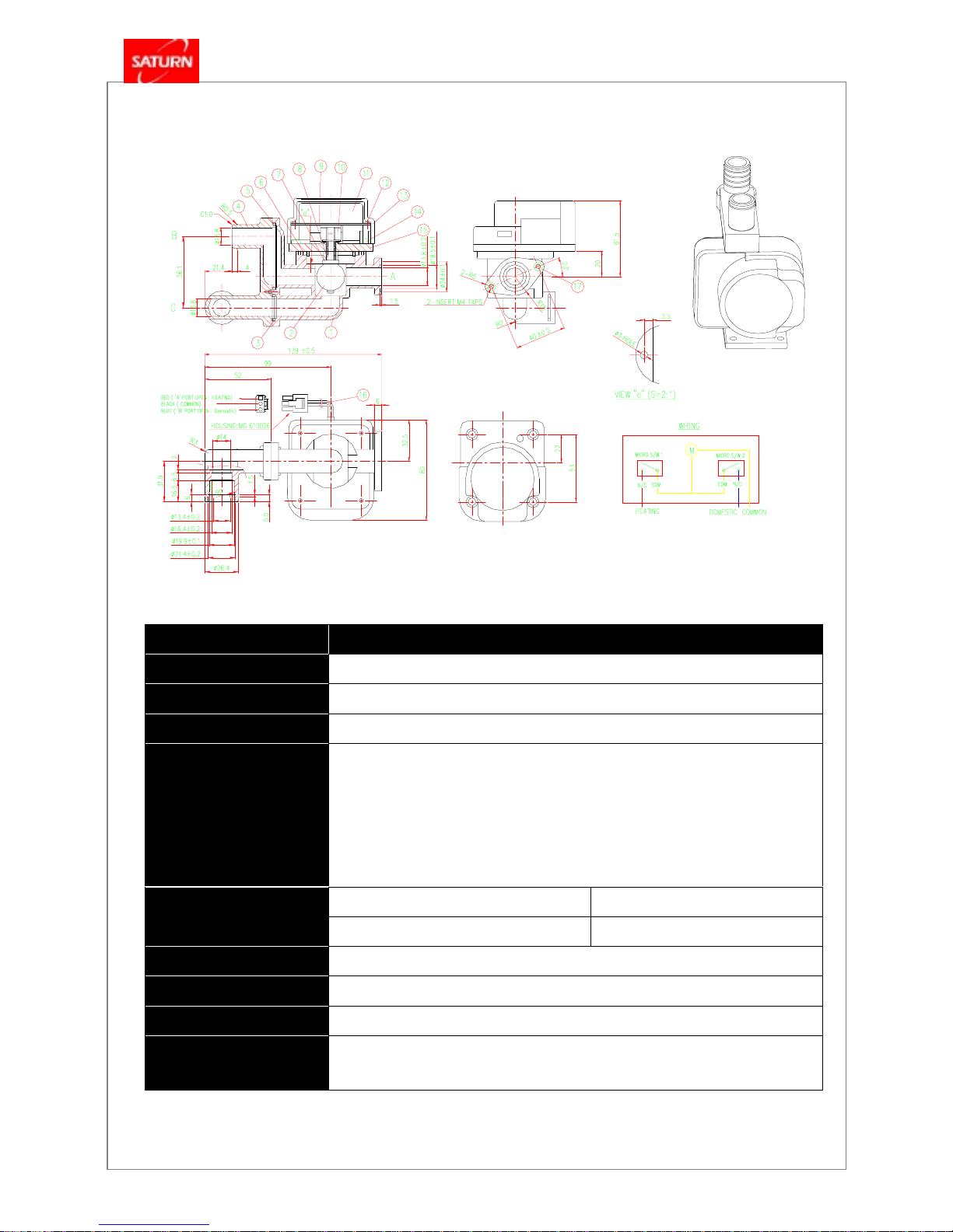
4.5 3-Way Valve
Item
All GOM models
Rated Voltage
AC 220V, 50 / 60Hz
Power Consumption
3 W
Body Material
NYLON 66
Function
- Block the passage of heating water by the flow detection in flow switch and flow
heating water into the hot water heat exchanger when use hot water, and lead to
exchanging the heat of hot water with heating water in the hot water heat
exchanger. (When stop using hot water, the water passage is changed over to
the way of heating pipe automatically.)
Heating → Hot Water 10 ± 2 sec
Operating Time
Hot Water → Heating 10 ± 2 sec
Wire Identification
y RED : Heating, y BLUE : Hot Water y BLACK : Common
Model
Motor Speed
2.5 ~ 3 RPM
Direction of Motor
Rotation
CCW
KDB-GOM
Series
- 17 -
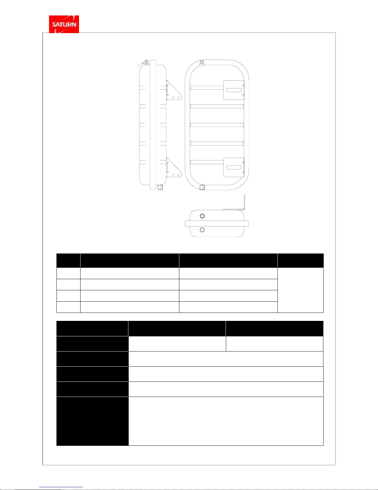
4.6 Expansion Tank
NO. Part Name Material Remarks
1 Body SBHG1 , 2.0t
2 Bracket SBHG1 , 2.0t
3 Diaphragm BUTYL , 2.0t
4 Nipple S10C , PF3/8”
Item KDB – 161 / 201GOM KDB – 251 / 301GOM
Vol um e
6.5 Liter 8.5 Liter
Body Material
SBHG 1
Charging Gas
Nitrogen
Charging Pressure
1.0 kg/cm2 (14.2 psig)
Function
y Vent the generated air in the heating pipe.
y Absorbs pressure generated in the pipe by the expansion of heating water due to
increasing temperature of heating water.
y Maintain the water volume in the boiler at a constant by low water level sensor.
Nitrogen gas
Charging point
KDB-GOM
Series
- 18 -
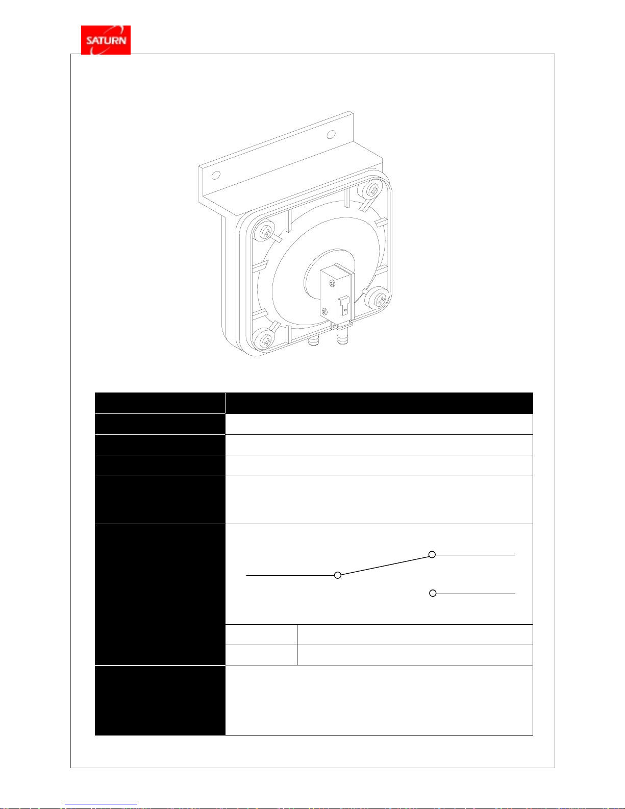
4.7 Air Pressure Switch
Item All GOM Model
Electric Rating
0.1A –125V AC, 0.1A –30V DC (Micro Switch)
Typ e
Differential Pressure Type (Vertical Type), Normal Close Type
Body Material
Nylon 66 (GF 30%)
Function
- Stop the combustion safely and automatically by monitoring the high pressure
or the adverse wind in the flue.
Contact Arrangement
ON more than 2.0 mmH2O
ON / OFF Operating
Pressure
OFF 7.0 ± 2 mmH
2
O
Reference
- Normal Close Type : The contact is always connected, and if the wind
pressure switch is operated by adverse pressure, this contact is opened and
stop the combustion in the boiler.
P3 (COM)
P1 (NC)
P2 (NO)
KDB-GOM
Series
- 19 -
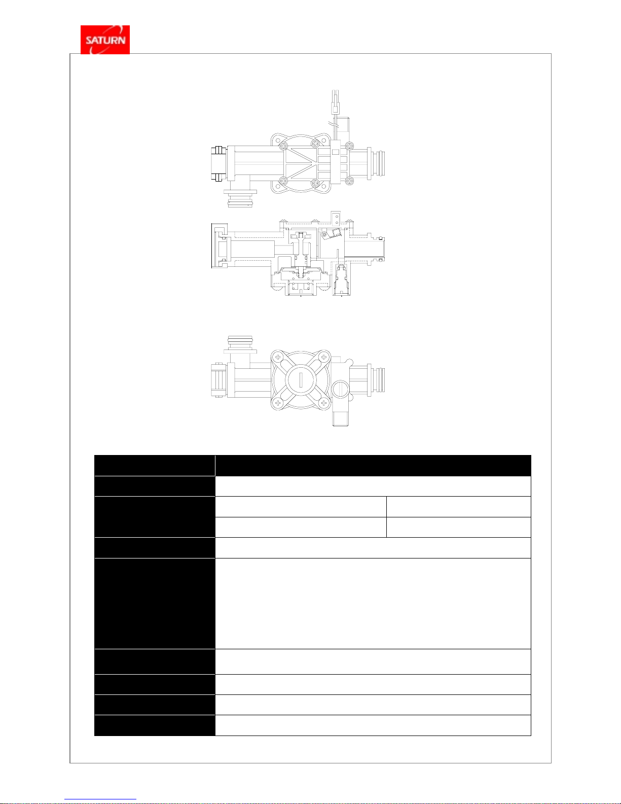
4.8 Hot Water Flow Switch
Item All GOM models
Body Material
Nylon 66 (GF 30%)
ON 2.3 ± 0.3 liter / min
Operating Flow
OFF 1.5 ± 0.5 liter / min
Installation Type
Horizontal Installation
Function
- When use hot water, detect the flow of hot water and transmit the signal to
controller, and operate 3-way valve to usable hot water.
- Reduce the pressure of discharging hot water in case of high water pressure
area (water supply pressure : more than 1.5 kgf/㎠) and maintain the optimum
condition of hot water use through flow limited by reduced pressure.
Reducing Pressure
Capability
P1 : 0.3 ~ 10 kgf/
㎠
→ P2 : 0.3
~
3.0 kgf/
㎠
Contact Rating
10 VA (W)
Maximum Contact Current
AC, DC 0.5A
Contact Resistance
less than 300 m
Ω
수동물보충

KDB-GOM
Series
- 20 -
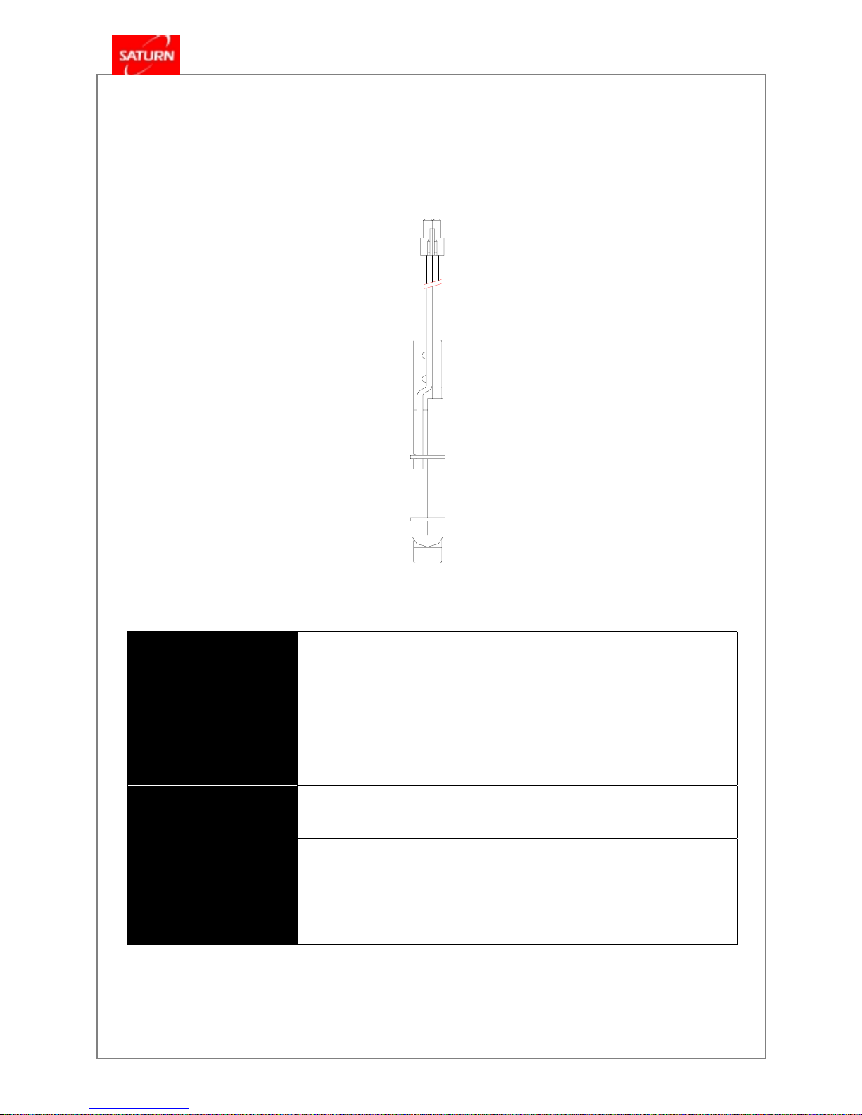
4.9 High Limit Sensor (Bimetal Type)
Function
- When the bimetal plate in the high limit sensor detects the increase in the
heating water temperature or in causing surface temperature, it is
transformed to move the shaft and to let the contact “OFF”
- The “OFF” signal from the high limit sensor is sent to the controllers so that
the check lamp on the room thermostat comes “ON” and the failure code
NO. 16 is displayed on the temperature indication. When the running is
resumed, only the check lamp is kept “ON”.
- In case of reduced discharge of combustion exhaust or overheat of heat
exchangers, the high limit sensor automatically cut off the gas control valve to
close it when the send the sensed the temperature of the heat exchanger
reaches 95 ℃ or higher. The check lamp on the room thermostat is lit and
failure code NO. 1 is indicated on the indication panel.
Model MS-1, Manual Reset
Type Bimetal Type
Operating Temp. 95
℃
Structure
Recovery Temp.
80
℃
Voltage Rating 125 ~ 250 V
Electric Rating
Current Rating 15 A
[Automatic, MS-1]
KDB-GOM
Series
- 21 -
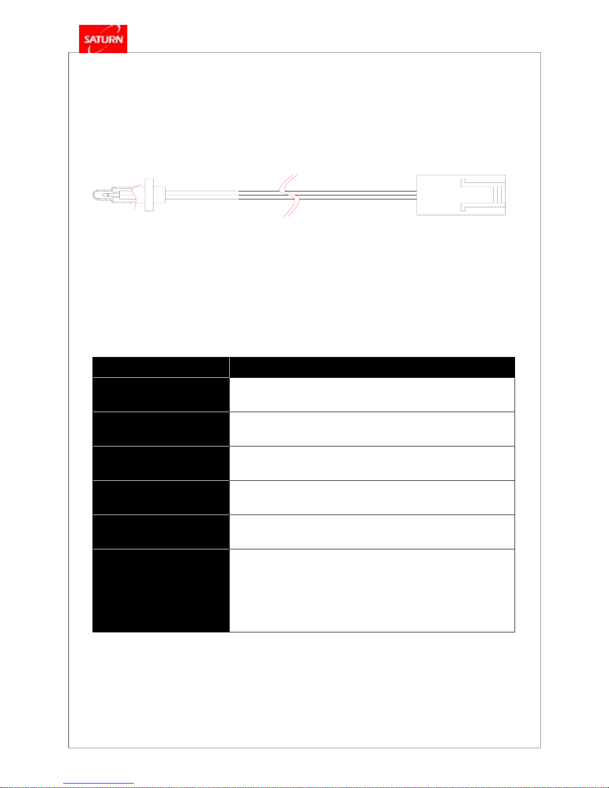
4.10 High Limit Fuse (Fuse Type)
Function
- In case of abnormal overheat of heat exchanger, the temperature of sensor
part will be more than 195 ℃, high limit fuse will cut off the power of
modulating gas control valve to close the modulating gas control valve and
secure the safety.
- Check lamp will on in the room thermostat and failure code # 03 will be
indicated.
Type Fuse Type
Structure
Operation Temp. OFF point: 195
℃
Electric Rating
Resistance
61.1 Ω at 20
℃
KDB-GOM
Series
- 22 -
4.11 Heating Temperature Sensor
Item All GOM models
Model No.
DKS - 902ET - 330C
Resistance
R50 = 3.485 ㏀ ± 3%
B Constant
R0 / R100 = 3449 K ± 1%
Thermal Radiation Constant
0.7
mW /
℃
Thermal Time Constant
Within 10 seconds
Function
- Detect the temperature of heating water and transmit the signal
to main controller. The main controller controls the flow of air /
gas needed for achieving and maintaining the setting
temperature.
KDB-GOM
Series
- 23 -
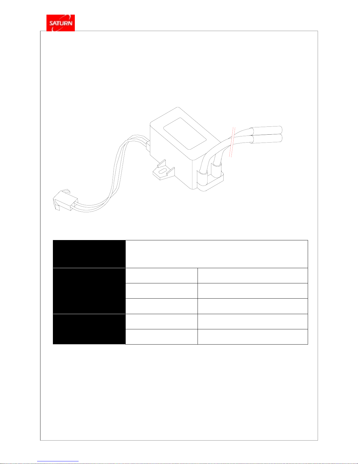
4.12 Ignition Transformer
Function
- Electric energy provides high voltage and current to the main burner for
ignition of gas.
Primary Rating AC 220 V , 50 / 60 Hz
Secondary Rating 19 kVo-p±2
Power Requirement
Secondary Current
7 mA±2
Casing Non-Combustible ABS
Structure
Cable Silicon
KDB-GOM
Series
- 24 -
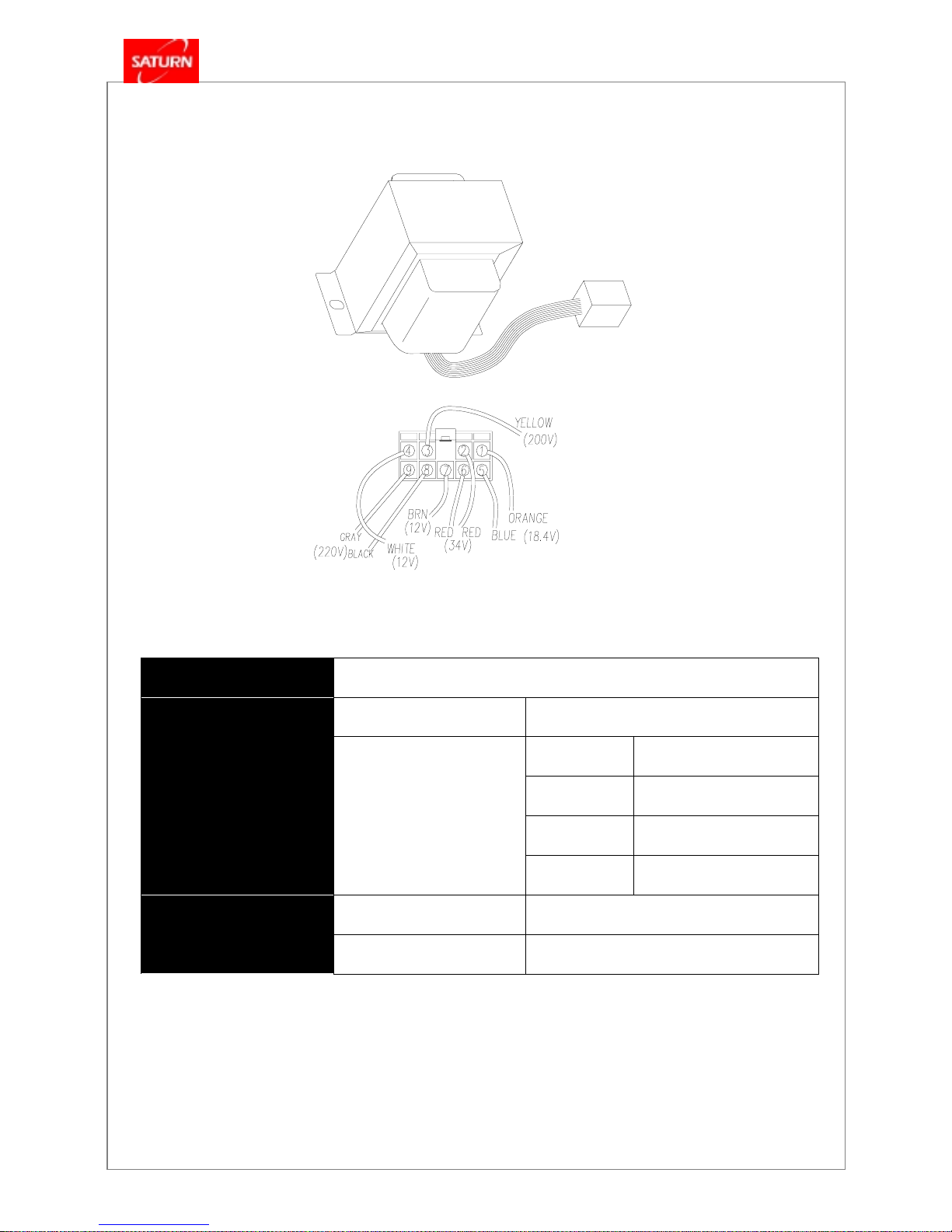
4.13 Power Transformer
Function
- Supply the power source to boiler.
Input Rating AC 220 V , 50 / 60 Hz
AC 220 V # 8-BLACK, # 9-GRY
AC 34.0 V # 2-RED, # 6-RED
AC 18.4 V # 1-ORANGE, # 5-BLUE
Power Requirement
Output Rating
AC 12.0 V # 4-WHITE, # 7-BROWN
Casing Non-Combustible ABS
Structure
Cable Silicon
KDB-GOM
Series
- 25 -
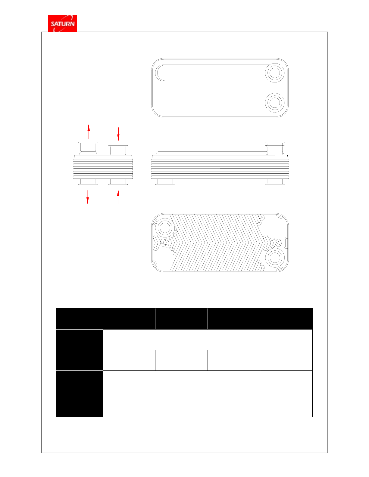
4.14 Domestic Hot Water Heat Exchanger
Item
161GOM 201GOM 251GOM 301GOM
Material
STS 304
Capacity
10 Pieces 12 Pieces 16 Pieces 18 Pieces
Function
- When use hot water, supply the heating water heated in main heat exchanger to hot water
heat exchanger and heat-exchange water (water supply) with heating water supplied in
hot water heat exchanger to be usable hot water.
Domestic Water
Outlet
Heating
Supply
Tap Water
Inlet
Heating
Return
KDB-GOM
Series
- 26 -
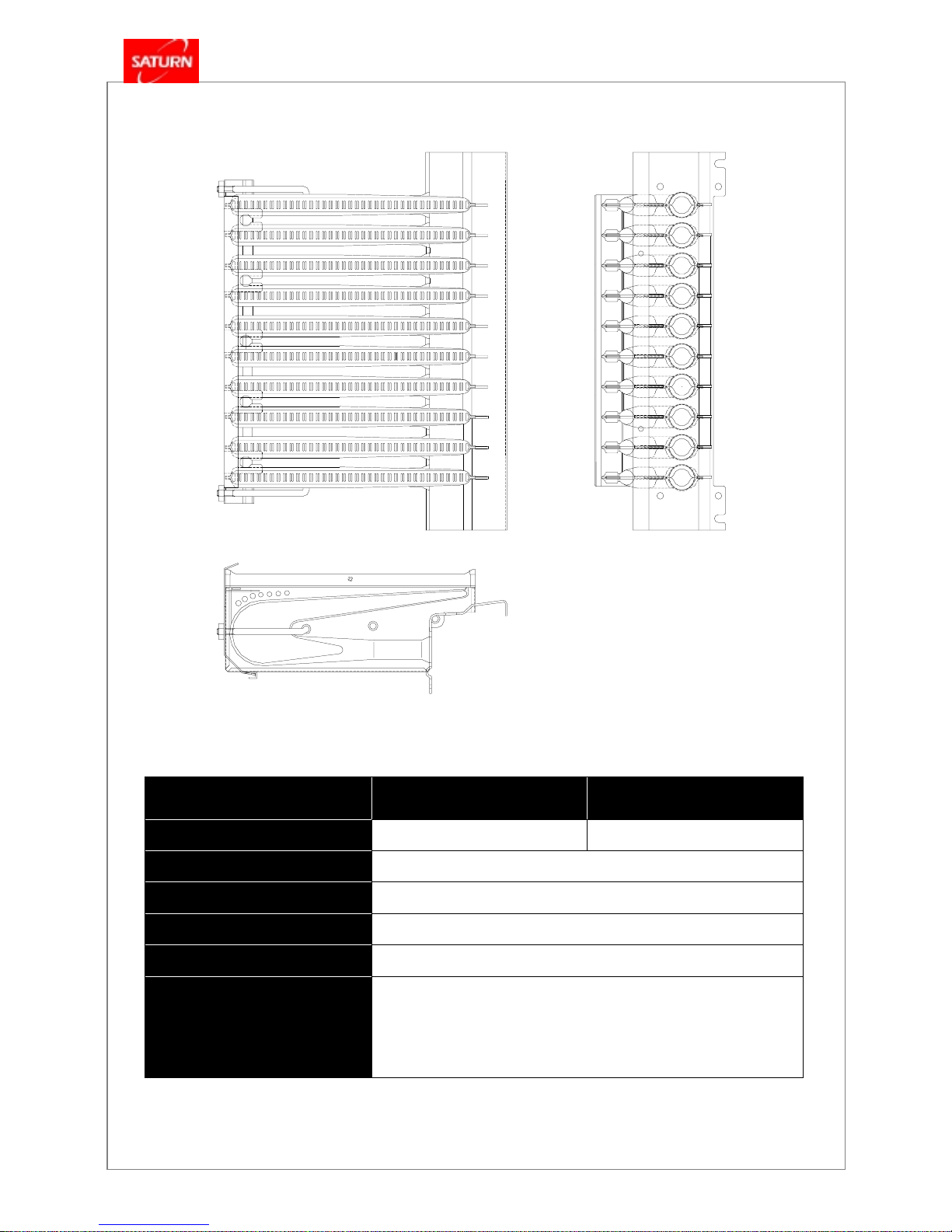
4.15 Burner Assembly
Item
161 / 201GOM 251 / 301GOM
Quantity of Secondary Nozzle
10 EA 15 EA
Material of Secondary Nozzle
ALSTAR
Slit (Flame Holder) Material
STS 430
Front Bracket
SBHG 1
Rear Bracket
STS 430
Function
- Supply heat sources by mixing and combusting the supplied gas and
air.
KDB-GOM
Series
- 27 -
4.16 Nozzle Holder Assembly
Item
161GOM 201GOM 251GOM 301GOM
Quantity of Primary Nozzle
10 EA 15 EA
Material of Primary Nozzle
C3602 BD
Material of Nozzle Holder
A6063S
LNG
φ
1.33
φ
1.46
φ
1.37
φ
1.50
Diameter of
Nozzle(mm)
LPG
φ
0.92
φ
1.06
φ
0.95
φ
1.06
Function
- Supply gas needed for combustion according to demands.
Secondary
gas pressure
measuring hole
KDB-GOM
Series
- 28 -
4
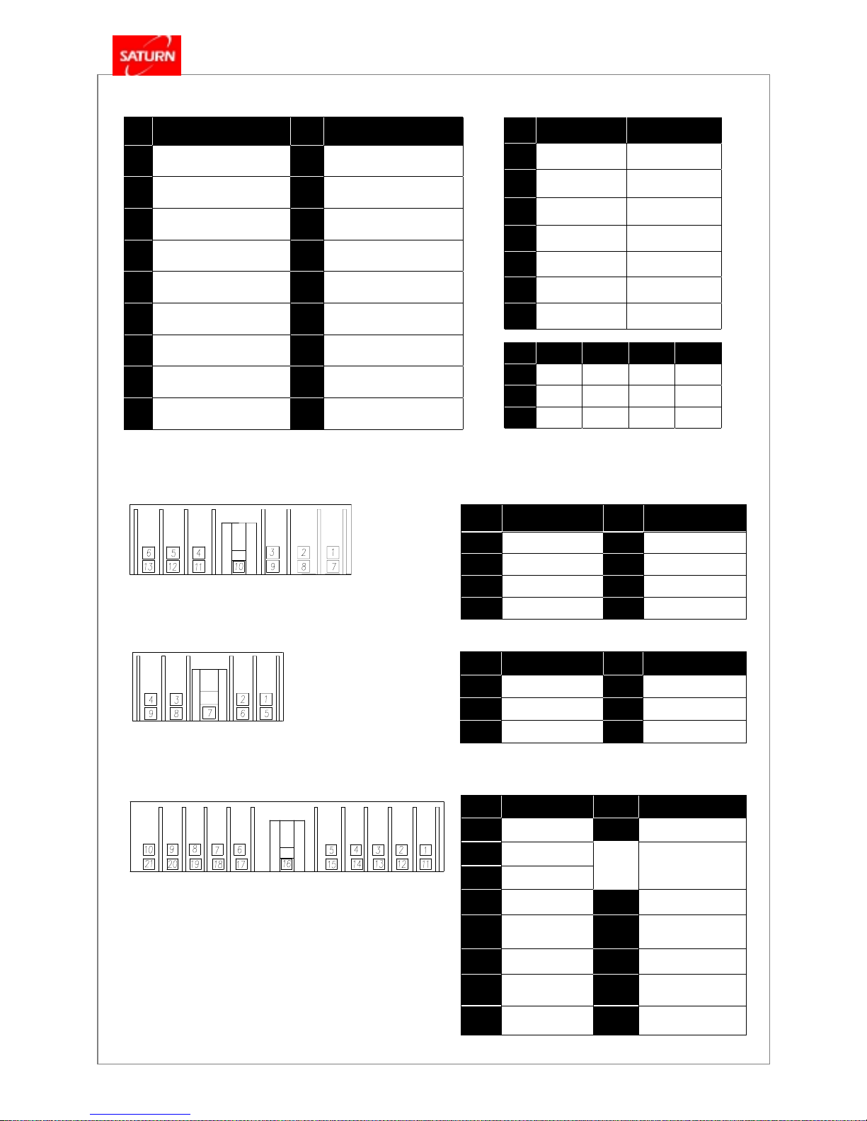
.17 Wiring Diagram
4
NO Function NO Function
1, 3
Gas Valve 1
7, 12
Ignition Transformer
2, 3
Gas Valve 2
8, 12
3-Way Hot Water
4, 11
AC 220V
9,13
3-Way Heating
5, 6
Circulation Pump
10
Ground
NO Function NO Function
1, 11
Water Filling
9, 20
Room Thermostat
2, 12
Fan
3, 13
Control Voltage
4
RPM Power Sourc e
14
RPM Input
5, 15
Heating Temp.
Sensor
15
RPM Ground
6 16
Flame Detector
7, 20
Air Pressure
Switch
17
Heating Flow Sensor
8, 20
Hot Water
Flow Switch
18, 19
Overheat
NO Function NO Function
1,5
AC 20V
4,7
AC 12V
2,6
AC 40V
8,9
AC 220V
3
AC 200V
4.17.3.3 21 Pin Wiring Connecting Diagram
4.17.3.2 9 Pin Wiring Connecting Diagram
4.17.3.1 13 Pin Wiring Connecting Diagram
4.17.3 Wiring Connecting Diagram
4.17.1 Fault repair codes (room thermostat, FR-5)
NO ON OFF
1
Trial Run Normal
2
Forced Max.
Combustion
Normal
3
Forced Min.
Combustion
Normal
4
FE FF
5
L.P. Gas Natural Gas
6
Close-Air Type Open Tank System
7
50 Hz 60 Hz
NO
161GOM 201GOM 251GOM 301GOM
8
OFF OFF ON OFF
9
ON ON OFF OFF
10
ON OFF ON ON
4.17.2 DIP S/W Setting on Main Controller
FND
No.
Problems FND
No.
Problems
01
Overheat
10
Air pressure failure
02
Low water level
11
Water level detection failure
03
Ignition failure
12
Flame failure in combustion
04
Flame sensor
(Lower gas pressure)
13
Heating water switch failure
05
Heating sensor wire
disconnected
14
Gas alarm(optional)
06
Short circuit of
heating sensor
15
MICOM failure
07
Hot water sensor wire
disconnected
16
Mechanical overheat
08
Short circuit of
hot water sensor
17
DIP switch setting error
09
Fan R.P.M. failure
18
KDB-GOM
Series
- 29 -
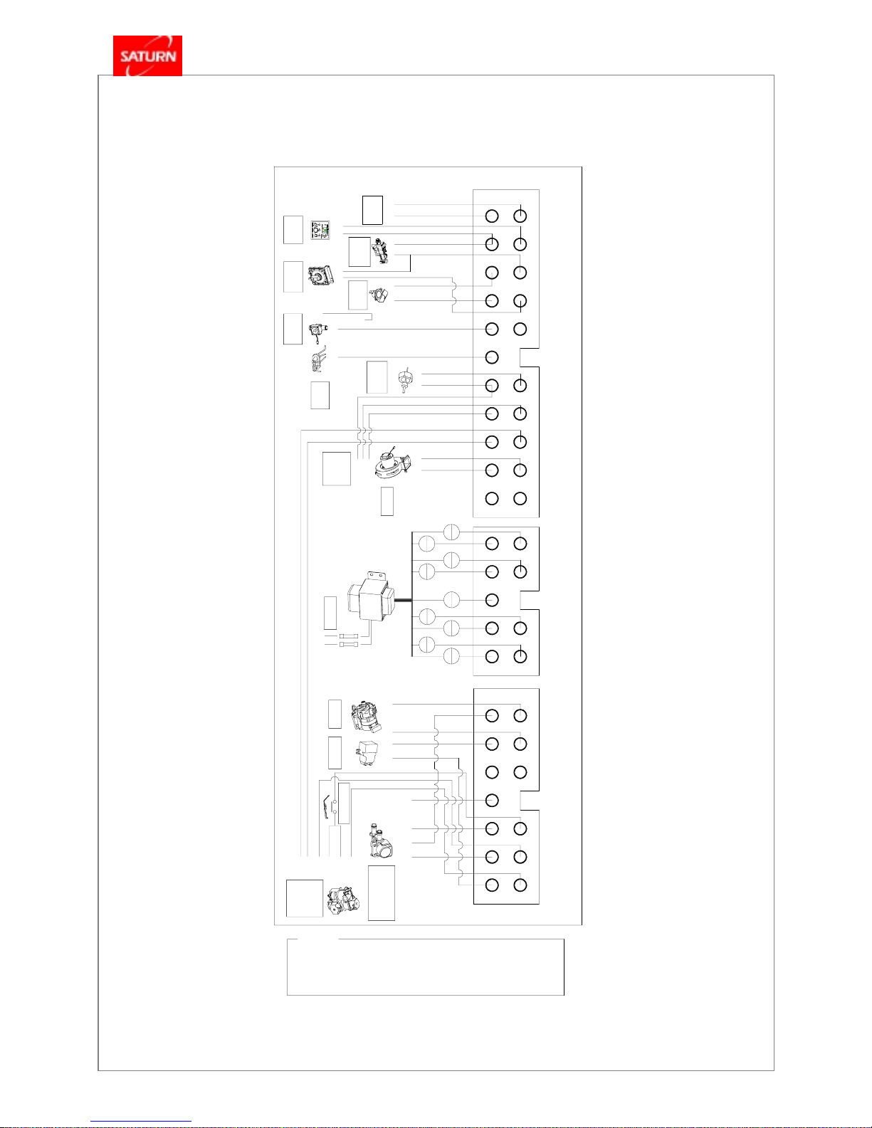
4.17.3 Wiring Diagram
WHT : WHITE
ORG : ORANGE
AC34V
AC220V
AC18.4V
IGNITION TRANS
LEGEND
GRY : GRAY
RED : RED
BLK : BLACK
BLK
2)BRN: Secondary valve
2)BLK: Currency
.
.
Modulation
YEL : YELLOW
BLU : BLUE
1)BLU : Primary valve
TIME UP 33-06
GAS VALVE
BLU
BLK
EV 1
BLU
BLU
RED
.
.
BRN
BRN
EV 2
HIGH LIMIT FUSE
2)BLK,BLU : HOT WATER
1)BLK,RED : HEATING WATER
THREE WAY VALVE
.
.
GRN
RED BLK
BLU
EARTH
AIR PRESSURE
: DC 5V : DC 5V
SWITCH
INPUT SIGNAL
HEATING FLOW
SWITCH
INPUT SIGNAL
: DC 20V
THERMOSTAT
INPUT SIGNAL
ROOM
: DC 5V
HOT WATER
FLOW SWITCH
INPUT SIGNAL
WHT
RED
SUPPLY POWER
BLK
WHT
FUSE , 3A - 2EA
PUMP
POWER TRANSFORMER
1)WHT : AC 5V
BLK
BLK
INPUT SIGNAL
: AC 200V
3)BLK : Ground
2)RED : DC 12V
FLAME
DETECTOR
EARTH
SUPERVISION
FAN ROTATION
BLK
RED
BLK
: DC 20V
YELYEL
GRN
PREVENTION
INPUT SIGNAL
OVERHEAT
SKYSKY
BLUBLU
ORG
BLK
RED
GRY
AC220V
: DC 5V
TEMPERATURE
HEATING WATER
INPUT SIGNAL
WHT
FAN
RED
RED
BLK
BLU
RED
RED
BLU
: DC 5 - 20V
68
F
50
176
3
86
99 4
F
2
Hrs
1
0
140
104
ORGORG
ALARM WIRE
INPUT SIGNAL
GAS LEAKAGE
BLK
BLK
RED
( - )
(+)
[13 PIN]
.
.
1
2
3
4
GRN : GREEN
BRN : BROWN
9
7
8
10
11
[9 PIN]
[21 PIN]
20
BLU
AC18.4V
RED
BRN
YEL
WHT
AC34V
AC12V
AC200V
AC12V
5
6
1
2
3
4
12
13
5
8
6
7
9
1
2
3
4
6
7
8
5
13
11
12
14
15
17
16
18
19
9
10
21
KDB-GOM SERIES WIRING DIAGRAM
AC220V, 50/60Hz
220VAC 50Hz
AC220V, 50Hz
AC220V, 50Hz
AC 220V, 50/60Hz
AC 220V, 50/60Hz
Operating Temp. : 156
°
C
KDB-GOM
Series
- 30 -
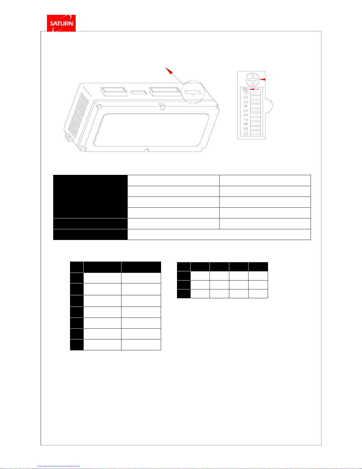
4.18 Main Controller
Voltage , Frequency AC 220V , 50 / 60 Hz
Voltage Range +10% to –15%
Ambient Temp. -15℃ to 70
℃
Electric Spec.
Ambient Humidity 45 – 90 %
Structure
Casing ABS
Model
KDC – 208-1M
4.18.1 DIP switch setting on main controller
4.18.2 Functions of Main Controllers
4.18.2.1 Pre-Purge
When the boiler operates, the function is to operate blower (fan) first and exhaust the remained air in the combustion
chamber before combustion starts, in order to prevent from immoderate ignition. Pre-Purge time is by achieving the fan’s
light-up RPM ± 200 rpm with more time than 4 ± 1 seconds.
4.18.2.2 Pre-Ignition
After Pre-Purge, the function is to operate ignition transformer previously in order to light up easily before supplying the
fuel (gas) for combustion. Pre-Ignition time is from ON time of ignition transformer till ON time of fuel supply device (gas
valve 2).
DIP Switch adjust part
Max. adjust screw
for secondary gas
pressure
NO ON OFF
1
Trial Run Normal
2
Forced Max.
Combustion
Normal
3
Forced Min.
Combustion
Normal
4
FE FF
5
L.P. Gas Natural Gas
6
Close-Air Type Open Tank System
7
50 Hz 60 Hz
NO
161GOM 201GOM 251GOM 301GOM
8
OFF OFF ON OFF
9
ON ON OFF OFF
10
ON OFF ON ON

KDB-GOM
Series
- 31 -
1 ± 1 second
4.18.2.3 Post- Ignition
The function is to keeps operation of ignition transformer until flame detector monitors and combustion flame is stable
after fuel supplied and ignited. Post-Ignition time is from the time of fuel supply till OFF time of ignition transformer.
4 ± 2 seconds
4.18.2.4 Post-Purge
The function is to exhaust the remained gas of combustion after flame extinguished when boiler stops. Post-Purge time is
from OFF time of fuel supply device till OFF time of fan.
Blower : 20 ± 2 seconds / Pump : 60 ± 6 seconds
4.18.2.5 Safety Shut-Off (No Light-Up)
The function is to stops fuel supply for safety when the flame signal isn’t detected even though boiler’s blower is operated,
and Pre-Purge, Pre-Ignition done and fuel supplied. Safety shut-off time is from ON time of fuel supply device till OFF time
of fuel supply. At that time, ignition transformer is also OFF.
3 ± 1 seconds
4.18.2.6 Boiler Stopping by Safety Shut-Off
If fuel supply and ignition transformer is OFF by the function of safety shut-off, the restarting operation
repeats (operation of Pre-Purge, Pre-Ignition, Fuel supply, Flame detection, etc by a series of control sequence) and
counts their cycle. If the number of safety shut-off is 3 times in series, transmits ignition trouble signal to the temperature
controller and fan is OFF after Post–Purge done. (Only if water temperature in the pipe is more than 80 ± 2.0
℃
, fan and
pump operate.)
4.18.2.7 Misfire (Flame Extinction or No Flame Detection) During Combustion
When misfire is monitored during combustion, stops fuel supply and performs the ignition operation by re-starting function
(Pre-Purge, Pre-Ignition, Fuel supply, Flame detection, etc by a series of control sequence) and counts their cycle. If the
number of fire loss is 10 times, fuel supply device is OFF and transmits the misfire signal to temperature controller, and
then fan is OFF after Post-Purge done. (Only if water temperature in the pipe is more than 80 ± 2.0
℃
, fan and pump
operate.)
4.18.2.8 Flame Detection during Pre-Purge (The Early Pseudo Flame)
When monitored flame signal during Pre-Purge time, stops to be progress even though Pre-Purge done, and transmits
the pseudo flame signal to temperature controller after checking continuously for 3 ± 1 seconds. Post-Purge performs in
series, and release automatically when pseudo flame is disappeared and then is returned the function as before. (Only if
circulation pump operate continuously until release the pseudo flame.)
4.18.2.9 Combustion Stop / Flame Detection during Standby (The Last Pseudo Flame)
When extinguishes by stopping fuel supply and performs Post-Purge, transmits the pseudo flame signal to the
temperature controller if flame isn’t extinguish actually or the flame signal is monitored during waiting combustion and isn’t
disappear within 3 ± 1 seconds. Post-Purge performs in series, and release automatically when pseudo flame is
disappeared and then is returned the function as before. (Only if circulation pump operate continuously until release the
pseudo flame.)
4.18.2.10 Low Water Level, Normal Water Level
When the power of boiler is ON, monitors always water level from low water level and normal water level sensor. If
monitors low water level that water is not enough in the boiler, the boiler stops running. Auto water filling valve is ON and
filling a boiler with water after pump is OFF, and transmits low water level signal to the temperature controller. (If the boiler
is filled with water by normal water level, the signal is released automatically and returned the status as before.) Closed air
type boiler doesn’t use normal level sensor and the heating water flow switch is attached on the low water level sensor. If
pump operates and heating water flow switch is ON within 6 ± 1 seconds, consider normal water level, and if heating
water flow switch is not ON, transmit abnormal status signal to temperature controller and pump is OFF and then
maintain this condition until restarting. (Only if water temperature in the pipe is more than 80 ± 2.0
℃
, fan operate.)

KDB-GOM
Series
- 32 -
4.18.2.11 Water Level Sensor Trouble (Opened Air Type)
If monitors water level that there are water at the normal water level sensor and no water at the low water level sensor,
consider the trouble of normal water level sensor or low water level sensor, and operates immediately a serial of operation
as same condition of low water level. (Only if water temperature in the pipe is more than 80 ± 2.0
℃
, fan operate.)
4.18.2.12 Heating Temperature Sensor Trouble
If finds the trouble of disconnection / short-circuit by checking heating temperature sensor as long as the power of boiler
is ON, the boiler is stopped (The burner stops and the pump / blower operate continuously, and stop the pump / blower
after temperature sensor is returned to normal and check water temperature to be less than 80 ± 2.0
℃
in the pipe.) and
the failure status of sensor is indicated in temperature controller.
4.18.2.13 Combustion Indication
Combustion indication in the temperature controller displays by the presence of flame signal. (Not by the presence of
fuel supply)
4.18.2.14 Air Pressure Switch
Air pressure switch is always ON regardless of blower. When air pressure is excessive, aind pressure switch is OFF
and the boiler is stopped and the abnormal status of air pressure is transmitted to the temperature controller. Blower
operates continuously and release automatically when return to normal state. (Only if water temperature in the pipe is
more than 80 ± 2.0
℃
, pump operates. The abnormality of RPM isn’t monitored in the abnormal status of wind pressure.)
4.18.2.15 Gas Leakage Alarm
When the gas leakage signal is input from outside, the boiler is stopped and blower operates to ventilate air. When the
gas leakage signal is released, the abnormal status is disappeared automatically and then returns to the status as before.
(Only if water temperature in the pipe is more than 80 ± 2.0
℃
, pump / blower operate.)
4.18.2.16 Pump Trouble
Water level control method of the closed air type boiler is decided by the input presence of flow switch within 6 ± 1
seconds after pump is ON. When there is no signal of flow switch within 3 ± 1 seconds, delay Pre-Purge by 6 ± 1
seconds. When the signal is, operate normally. If flow switch is ON continuously more than 15 ± 3 seconds before pump
operates, consider the trouble of pump or flow switch and transmit abnormal status to the temperature controller. Pump is
OFF and maintains this status until re-operate the temperature controller. (Only if water temperature in the pipe is more
than 80 ± 2.0
℃
, fan operate.)
4.18.2.17 Time Multiple Function When Control Heating
When heating combustion operates continuously at a steady heating value by heating command of the temperature
controller, calculate average heating value and is converted into running time / stop time according to heating value. And
then maintain the stopping state (same as outdoor state) for regular time after running combustion for regular time. If
changed heating command or setting temperature in the temperature controller or operated hot water combustion, etc
except heating function within heating running time or forced stop time, the time should be always initialized. (Only in hot
water combustion, it doesn’t stop function.)
4.18.2.18 MICOM Trouble
As the part of deciding trouble inside of the controller, considers that there is trouble of MICOM when external AC
power of 50/60Hz isn’t monitored, stops all output and transmits trouble status to the temperature controller and then
maintains the current state until re-operate the temperature controller. (If water temperature in the pipe is more than 80 ±
2.0℃, pump operate.)
4.18.2.19 Heating Control when Hot Water Use
Proportional control uses the indirect control method of hot water temperature by heating water temperature and hot
water temperature is as follows.
In case of FR-5 use, water temperature in the pipe is 80℃ when choose heating, and is set 70℃ when choose
outgoing and hot water .
4.18.2.20 Heating Temperature Control
The temperature of heating water at the discharge may be set in the range of 30~80±4.0℃ at the room thermostat. If
the temperature of the heating water is lower than 83℃, the ratio control(PID) will be performed in accordance with the
specified procedures.
If the range of control has been exceeded due to the change in the set temperature or to abrupt change in flow, the set
temperature will be reached through the proportional control with the delay of 300±15 seconds.(If 83±4.0℃ is exceeded,
the delay of 30±3 seconds will not be performed.)

KDB-GOM
Series
- 33 -
ON/OFF Control Range
Set Temperatures (“T” set)
ON OFF
80
℃
“T” set - (18±2)
℃
“T” set - (5±2)
℃
70 ~ 77
℃
“T” set - (14±2)
℃
“T” set - (7±2)
℃
60 ~ 69
℃
“T” set - (12±2)
℃
“T” set - (6±2)
℃
50 ~ 59
℃
“T” set - (10±2)
℃
“T” set - (5±2)
℃
40 ~ 49
℃
“T” set - (8±2)
℃
“T” set - (4±2)
℃
30 ~ 39
℃
“T” set - (6±2)
℃
“T” set - (3±2)
℃
If the combustion is delayed due to the temperature increase as above, the pump will be continuously run and the
resumption of combustion will be delayed for 300±30 seconds. (If the combustion stops at 85℃, the forced delay of 300
seconds will not be executed.)
If other functions than the heating, such as a different function or change in the set temperature, is performed during the
heating time or forced stop time, the time should be changed to the initial value.(In the case of heating domestic hot water
supply, the boiler will not be stopped.)
4.18.2.21 Re-Use Standby after Use Domestic Hot Water
When hot water flow switch is OFF by stopping use of hot water, fuel supply stop. Fan doesn’t perform Post-Purge
caused by stopping fuel supply and maintains ON status for 90 ± 9 seconds. If hot water flow switch is ON within this time,
performs pre-Ignition, fuel supply, flame detection, and Post-Ignition. And return the status as before when expires 90 ± 9
seconds after using hot water.
Only if the heating signal is input in the temperature controller during hot water standby (90 ± 9 seconds) or after hot
flow switch is OFF, turn immediately to heating. At this time, combustion should start always from the beginning after
combustion is OFF, and Post-Purge time is 15 ± 3 seconds and hot water standby time progress separately.
4.18.2.22 Freezing Prevention
When heating water temperature is lowered less than 10 ± 2.0℃, circulation pump operates for 30 ± 2 seconds by the
interval of one hour. If circulated water temperature is lowered less than 6 ± 2.0
℃
, operates circulation pump and starts
combustion for freezing prevention after output of freezing running in temperature controller. When the heating water
temperature is more than 21 ± 2.0
℃
, the circulation pump and combustion stop.
4.18.2.23 The Number of Fan Rotation Trouble
The RPM signal monitors after running fan and the related status is indicated in the temperature controller as follows.
- After reaching within ignition rpm ± 200rpm during ignition, ignition is started by controlling gas valve. If it doesn’t reach
within 13 ± 2 seconds, consider as one time failure of ignition. When re-ignition is performed and it doesn’t reach for 3
times in series within 13 ± 2 seconds, stop the ignition. After perform purge for 15 ± 2 seconds, start re-ignition again.
(Only if repeats for 10 times of the above operation and doesn’t ignite, consider as the number of rotation trouble.)
- If ignite normally and progress the combustion, initialize the count of above operation.
- If the number of rotation maintains less than 400 ± 200rpm or more than 3200 ± 200rpm for 12 ± 1 seconds during
normal combustion, consider as the RPM trouble.
- When the RPM trouble is happens by the above mention, re-check trouble of blower for 30 ± 3 seconds after indicating
first the trouble status in the temperature controller. If decide as normal status (1000 ± 200rpm), release it automatically
and return to normal status.
4.18.2.24 Bimetal (Mechanical Type) Overheat Control
When overheat signal is monitored continuously for 1 ± 1 second from mechanical overheat sensor during combustion
and stopping, transmits bimetal overheat status to the temperature controller and safety shut-off performs. Fan and
circulation pump operate continuously and stop when heating water temperature is less than 80 ± 2.0
℃
.
4.18.2.25 DIP Switch Setting Trouble
The voltage of wind pressure switch is always monitored during combustion and stopping of the boiler, and it is
compared with current setting of DIP switch. When finds trouble, indicates trouble status in the temperature controller and
stops combustion. (Only if set normal status, release automatically.)

KDB-GOM
Series
- 34 -
4.18.2.26 Test Operation Function
- It is priority of the set function of DIP switch.
- Pump operates for 2 hours. In case of open type, operate continuously after auto water filling when low water level is
happens.
- If releases test operation by manipulating DIP switch in standby status after performing test operation and sets again,
initializes test operation function and starts test operation.
- When low water level (pseudo flame) happens in case of closed air type, releasing automatically by the interval of one
minute and progresses continuously.
- When flow switch is ON in case of closed air type, stops pump and checks trouble.
- When DIP switch sets test operation, the power lamp flickers by repetition of ON for 1 second and OFF for 1 second.
4.18.2.27 Forced Maximum / Minimum Combustion Function
- When change-over switch sets to forced Max or forced Min, combusts by the set Max or Min according to the capacity
of the boiler after normal ignition. (PID control doesn’t.)
- When DIP switch sets for both forced Max and Min at the same time, combusts by forced Min.
- During combustion of forced Max / Min, operation of stopping time isn’t performed.
- If the test operation is ON in status of forced Max/Min operation, the function of forced Max / Min operation isn’t work.
4.18.2.28 Fault repair codes(room thermostat, FR-5)
FND No. Problems FND No. Problems
01
Overheat
10
Air pressure failure
02
Low water level
11
Water level detection failure
03
Ignition failure
12
Flame failure in combustion
04
Flame sensor
(Lower gas pressure)
13
Heating water switch failure
05
Heating sensor wire disconnected
14
Gas alarm(optional)
06
Short circuit of heating sensor
15
MICOM failure
07
Hot water sensor wire disconnected
16
Mechanical overheat
08
Short circuit of hot water sensor
17
DIP switch setting error
09
Fan R.P.M. failure
18
4.18.2.29 Current Proportional Range Compensation
- Maximum current change by adjusting variable resistor for maximum current compensation.
- Current compensation range can be variable more than ± 20mA of maximum current.
4.18.4.30 The Others
- Heating flow switch is used to monitor water level of closure type (closed air type).
- Power lamp is always lit in the condition of power ON and flickers by the repetition of ON for 0.5 second and OFF for 0.5
second in the abnormal condition.
4.18.2.31 Secondary Gas Pressure according to Capacity of Boiler (mmAq)
Model High Load Low Load
NG 104 20
KDB – 161 GOM
LP 170 20
NG 104 20
KDB – 201 GOM
LP 150 30
NG 104 20
KDB – 251 GOM
LP 165 38
NG 106 20
KDB – 301 GOM
LP 156 30

KDB-GOM
Series
- 35 -
1. Precautions before installation
1.1 Shipping from factory
1.2 Choosing the best location
1.3 Methods of installation
1.4 Check the kind of gas
1.5 Precautions for installation
2. Identifying the components of the boiler
3. Installation of water piping
4. Installation of the flue
4.1 PVC Venting Method
4.2
Flue pipes used for Standard Flue Kit models
5. Gas piping connections
6. Installation of the room thermostat
6.1 Choosing the Best Location
6.2 Installation
II.
Installation of Boiler & Accessory

KDB-GOM
Series
- 36 -
■
WARRANTY WILL BE CONSIDERED VOID IF THIS EQUIPMENT IS INSTALLED BY ANYONE OTHER THAN A
QUALIFI ED, TRAINE D AND L ICEN SED ( WHERE APPLICABL E ) HE ATING TECHNICIAN.
■
KYUNGDONG BOILER CORPORATION IS NOT RESPONSIBLE FOR PROBLEMS OR DAMAGE CAUSED BY IMPROPER
INSTALLATION IN CONSISTENT WITH THIS M ANUAL.
■
THE IN STALLING CO NTRACTOR M UST I NSTRUCT THE OWNE R ON THE FU LL OPERATION OF THIS PRODUCT.
■
THE INSTAL LI NG CON TRACTO R M UST GI VE THE OWNE R THE APPO RPR IATE WARRANTY CERTIFICATE AFTER
THE IN STAL LATIO N H AS BEE N CO MP LETE D.
1. Precautions before installation
1.1 Shipping from factory
The units are released from our facility specially packaged to prevent handling damage and contamination in transit.
Dropping or throwing the boilers or moving them while outside of their shipping container may cause damage or
internal contamination by any moisture remaining after testing. Do not stand the boilers up by resting on the
connections piping.
1.2 Choosing the best location
■
Never locate the unit outdoors,
Such as an open porch or patio or exposed to the wind, rain snow and cold temperature.
Special consideration must be given to where the venting will terminate outdoors.
■
Do not locate the unit in an equipment room that has an exhaust fan.
■
Install the unit securely on any non-combustible wall that is capable of supporting the 40 kg weight of this
equipment.
■
Maintain an 150mm clearance to the left and right of unit including 150mm clearance in front of the unit for safety
inspections and future access.
■
Do not install unit in an underground or semi-underground location unless using the model FF or designated
concentric flue kit for KDB-GOM models.
■
When installing the unit, consideration must be given to the proper location. The location selected should be as
close to the vent pipe termination outside the building, and as centralized with the water piping system as
possible.
■
A minimum clearance of 100mm must be allowed for access to replaceable parts such as the thermostats, drain
valve and relief valve.
■
As the gas boiler is to be installed indoors, they shall not be installed outdoors, such as in the porch.
■
Do not install boiler on combustible wall in a high humidity location.
There is a risk in using fuel burning appliances in rooms or areas where gasoline, other flammable liquids or engine
driven equipment or vehicles are stored, operate or repaired. Flammable vapors are heavy and travel along the floor
and may be ignited by the igniter or main burner flames causing fire or explosion. Some local codes permit operation of
gas appliances if installed 18-inches or more above the floor. This may reduce the risk if location in such an area cannot
be avoided.
Flammable items, pressurized containers or any other potential fire hazardous articles must never be placed on or
adjacent to the boiler.
Open containers of flammable material should not be stored or used in the same room with the boiler.
1.3 Methods of installation
■
The units must be firmly secured on the wall, which can sufficiently hold the unit weight.
■
Exhaust vent pipe has a maximum length of 5.0M with up to 3-90° elbow. Vent pipe must be angle 2-3° toward
the boiler to return condensate.
■
The units should be grounded to prevent electric shock.
1.4 Check the kind of gas
■
Check if the gas indicated on the rating plate is being used. If not, change the nozzle
by consulting the service center or dealers.

KDB-GOM
Series
- 37 -
CONVERSION OF THIS APPLIANCE FROM NATURAL GAS TO PROPANE OR PROPANE TO NATURAL GAS
CAN ONLY BE PERFORMED by a QUALIFIED TECHNICIAN.
1.5 Precautions for installation
■
Piping for heating and hot water should be cleaned before connecting to the unit.
Lime scale accumulation can reduce the life of the equipment, reduce efficiency and waste fuel. Boiler failure due to
lime or scale buildup voids the warranty.
Check the metal tag on the relief valve and compare it to the heater’s rating plate. The pressure rating of the relief valve
must not exceed the working pressure shown on the rating plate of the heater. In addition, the hourly heat capacity
rated temperature discharge capacity of the relief valve shall not be less than the input rating of the heater. NO VALVE
IS TO BE PLACED BETWEEN THE RELIEF VALVE AND TANK. DO NOT PLUG THE RELIEF VALVE.
The drain line connected to this valve must not contain a reducing coupling or other restriction and must terminate
near a suitable drain to prevent water damage during valve operation. The drain line shall be installed in a manner to
allow complete drainage of both the valve and line. DO NOT THREAD, PLUG OR CAP THE END OF THE DRAIN
LINE.
■
The boiler needs a large quantity of air for combustion, the specified vent must be
installed. Incomplete combustion will occur and prevent normal operation of the boiler.
For safe operation, an ample supply of air must be provided for proper combustion and ventilation in accordance with the national fuel
gas code or applicable provisions of the local building codes (latest editions). An insufficient supply of air may result in a yellow, luminous
burner flame, carboning or sooting of the finned heat exchanger, or create a risk of asphyxiation. Do not obstruct the flow of combustion
and ventilation air.
NEVER OPERATE THE HEATER UNLESS IT IS VENTED TO THE OUTDOORS AND HAS ADEQUATE AIR
SUPPLY TO AVOID RISKS OF IMPROPER OPERATION, FIRE, EXPLOSION OR ASPHYXIATION.
■
The boiler should be at least 600mm away from electric appliances.
The boiler is set up for AC 220V, 50/60Hz.
The flow of combustion air to the boiler must not be obstructed.
The boiler area must be kept clear and free from combustible materials, gasoline and other flammable vapors and
liquids.
■
Flue made of stainless steel.
■
To facilitate the discharge of exhaust gas, the flue
should be installed with fewest possible bents and
curves. The flue should have a diameter larger than
that of the flue of the boiler.
■
Do not place flammable item near the boiler.
Never place combustibles such as vinyl bags,
match, thinner, etc on boiler.
Read first before connection to power supply
Low Voltage
(Thermostat Wire)
Orange
Orange
Blk
Red
Black
White
Green
Low Voltage
(for optional gas alarm)
Gray Wire
(to live voltage)
More than 600mm
Only for AC220V, 50Hz

KDB-GOM
Series
- 38 -
2. Identifying the components of the boiler
■
Model : KDB – 251 / 301GOM
■
Model : KDB – 161 / 201GOM

KDB-GOM
Series
- 39 -
3. Installation of water piping
■
The piping materials used should meet local codes and industry standards.
■
Piping must be cleaned and flushed-out before installation.
■
Do not apply torch heat within 300mm of the bottom connections of the unit.
■
Perform all solder connections at a safe distance from the (brass) male
connectors below the unit. Allow fittings to cool, before attaching to unit. Use only approved coupling unions with
O-rings to attach field piping to unit.
■
The ‘heating’ pipe should be 3/4" and of type-L copper. Never use aluminum, plastic, or galvanized steel piping.
■
The pipe size used for supply heating water should be the same size used for the return heating water.
■
Use only copper piping with lead-free solder for the domestic water side.
■
Since the expansion tank has already been installed in the unit, no separate tank is required.
■
The size of the domestic hot water pipe should be 1/2" diameter.
■
The length of piping should be as short as possible and the piping should have minimal number of bends and
connections.
■
Use only ball type isolating valves. Do not use gate valves.
■
Never leave the heating pipes disconnected while operating the unit as a boiler. This will cause damage to the
heat exchanger and void the manufacturers warranty.
■
All piping should be insulated.
■
After making the piping connections, check for gas or water leaks.
■
If the water supply pressure is 10 kgf/cm² or higher, install the reduction valve on the water supply piping.
■
If the water supply pressure is 0.3 kgf/cm² or lower, install a pressurizing pump.

KDB-GOM
Series
- 40 -
A THERMOSTATIC MIXING VALVE MUST BE ADDED TO THIS SYSTEM TO PREVENT SCALDING. IF YOU
CANNOT FIND A MIXING VALVE LOCALLY, PLEASE CONTACT YOUR QUIETSIDE DEALER OR LOCAL
SPECIALITY PLUMBING SUPPLIER.
Mixing type valve:
- Controls the desired hot water temperature and ensures constant hot water temperature in the faucets
- Ensures safety through the built-in anti-burn/scald safeguard. Limits the deposits and accumulation of scale.
- Includes built-in wire mesh filters and check valves for long and trouble-free operation.
Fig. Schematic of piping installation
There is a risk in using fuel burning appliances in rooms or areas where gasoline, other flammable liquids or engine
driven equipment or vehicles are stored, operated or repaired. Flammable vapors are heavy and travel along the floor
and may be ignited by the igniter or main burner flames causing fire or explosion. Some local codes permit operation of
gas appliances if installed 5.0M or more above the floor. This may reduce the risk if location in such an area cannot be
avoided.
Flammable items, pressurized containers or any other potential fire hazardous articles must never be placed on or
adjacent to the boiler.
Open containers of flammable material should not be stored or used in the same room with the boiler.
DO NOT INSTALL THIS BOILER DIRECTLY ON A CARPETED FLOOR. A FIRE HAZARD MAY RESULT. INSTEAD
THE BOILER MUST BE PLACED ON A METAL OR WOOD PANEL EXTENDING BEYOND THE FULL WIDTH AND
DEPTH BY AT LEAST 75mm IN ANY DIRECTION. IF THE HEATER IS INSTALLED IN A CARPETED ALCOVE OR
CLOSET, THE ENTIRE FLOOR SHOULD BE COVERED BY THE PANEL.
99 F
50
113
104
ROOM TEMP.
140 F
OFF
MAX
122
68
131 86
77

KDB-GOM
Series
- 41 -
4. Installation of the flue
4.1 PVC Venting Method
■
The KDB-GOM Series boiler may be vented using 75mm schedule-40 venting materials.
■
Cut all lengths of pipe cleanly maintaining a 90-degree square edge. Use long radius elbows whenever possible.
■
Use only the type of adhesive recommended by the stainless pipe manufacturer.
■
Keep an uphill slant from boiler to the outside to ensure that all condensed water inside the pipe will return back to
the boiler.
■
Do not place the outdoor termination kit in an area where discharge gasses will be directed towards evergreen
shrubbery.
■
Assemble the flue using the following illustration as a guide. Your installation may vary slightly from the illustration
shown below.
Use the optional Vent Termination Kit for venting the KDB-GOM boiler to outside area.
Use the optional Vent Termination Kit for venting the KDB-GOM boiler to outside area.Use the optional Vent Termination Kit for venting the KDB-GOM boiler to outside area.
Use the optional Vent Termination Kit for venting the KDB-GOM boiler to outside area.
- Standard : The Stainless Steel Concentric Flue Kit for KDB-GOM models.
“A” : 75
㎜×
㎜×㎜×
㎜×
1.0m LENGTH STAINLESS FLUE PIPE
“B” : 75
㎜×
㎜×㎜×
㎜×
0.5m LENGTH STAINLESS FLUE PIPE
“C” : 75
㎜×
㎜×㎜×
㎜×
90-DEG. STAINLESS ELBOW
Shown : 75
㎜㎜㎜㎜
(3
″″″″
) Stainless Venting.
“C”
“A” or “B”
(Maximum Allowable
Flue Length = 5 m)
Min. 250㎜ (10″)
Vent Termination Kit
Exhaust
Intake Air
Min. 600㎜ (2 ft) from ground
(Note! - Install the vent termination kit in an
area away from plants,
people and
animals)
φ75㎜
(3
″″″″
)
Type 304
stainless steel
only
NOTE
ⅰ) Intake Air : φ75㎜ (3
″″″″
) stainless steel.
ⅱ) Exhaust : φ75㎜ (3
″″″″
) Stainless steel.
ⅲ) Maximum three 90° elbows.
ⅳ) Slant flue pipe 2-3° away from boiler to outside,
to drain condensate.
Ground
KDB-GOM
BOILER
“C”
To Dr a i n
Install Horizontal Drip
Te e
If Required

KDB-GOM
Series
- 42 -
4.2 Flue pipes used for STS exhaust flue kit
■
When the flue duct (including extension) passes through a combustible wall or ceiling with combustible materials,
it should be insulated with 25mm or thicker insulation and then set apart from the wall or materials by 50mm or
more. When it passes through the ceiling, include an opening for inspection of the flue.
■
If the air supply duct is separated from the flue duct, the total length of the flue duct should be 3.0 M or less and
with 2 or less elbows.
■
The connection of the air supply hose must be sealed by the wire clamp to prevent any air loss. In the connection
of the flue duct and the flue elbow, In O-ring must be inserted to prevent leakage.
■
Do not use any aluminum duct as an extension. Use extension duct sets or elbows available through your
kyungdong distributor.
■
The flue duct which carries combustion waste gas should be firmly secured by the clamp so that it will not loosen
due to vibration. The parts where the band clamp is not used should be sealed with aluminum tape.
In the event the exhaust pipe passes through a combustible wall or an combustible ceiling, insulate it with
nonflammable materials of 25mm thick or more and locate 50mm or more away from any combustible materials.
In addition, install a check port if flue passes through the ceiling.
Tie up a joint of the air intake hose with the wire clamp so as not produce a loss of an intake air, insert an O-ring in a
joint of the exhaust pipe and exhaust elbow so that the exhaust gas won’t leak.
Fix the exhaust pipe with the band clamp and screws so as not to pull due to shock. Make sure to wrap any pipe joint
not using a band clamp with aluminum tape.
Fig. Schematic of Standard Flue kit Installation
Ceiling
Seal opening to ensure that burne
d
waste gas does not enter the room.
In the event the intake hose is to
o
long, cut the shortest length as
possible and connect it.
Nonflammabl e
wall
150 or more
250or
more
500 or
more
Install the horizont al part of flue downwards(120mm)
so that the condense d water from the flue or rain doesn’t enter
into the boiler.
Install the flue in a place where there are no any obstacle
s
within 1.5M away from the flue.
Install the flue ensu ring no that it cannot be blocked by sno
w
falling from the roof eaves.
Install the flue in a place in a location opening exist within 500 m
m
from the flue so that exhaust gas can’t re circul ator in to the building.
Install the flue at least 600mm above the ground.
Unit : mm

KDB-GOM
Series
- 43 -
5. Gas piping connections
■
The heating water supply piping should be 3/4". An isolation (ball-type) valve should be installed before the piping is
connected to the units.
■
Black iron piping or 3/4" flexible connector (approved by the local authorities for gas) should be used for gas piping.
■
Do not use Teflon tape for gas pipe connections.
■
Install a gas drip leg at the unit.
■
Gas piping should be kept at the required distance away from any electric lines and the main service panel(check
with local authorities).
Items Distance (mm)
1. Distance from electric lines 150
2. Distance from electric heaters and electric panels 600
3. Distance from flue pipes and outlets 300
■
Install the ball valve(cut-off valve) before connecting the gas piping to the unit (Allow space for the lever’s full
movement, install valve as close to the units as possible).
■
After the gas pipe has been completed, all connections must be checked with soapy water.
Note!
- Do not test for
gas leaks by pumping air-pressure into the line without first disconnecting the gas line to the unit. Pressuring the
unit will void the manufacturers warranty. Releasing this pressure into the unit will cause immediate and severe
damage to the gas valve and its internal pressure regulating device and could result in property damage and/or
personal injury.
6. Installation of the room thermostat
6.1 Choosing the Best Location
■
Never locate the thermostat near or above a heat producing source(lamp, TV, fireplace, radiator, direct sunlight,
etc.).
■
Never locate in areas with drafts(stairwells, vestibules, foyers, against an outside/exterior wall, etc.).
■
Never locate in a room, which will be shut-off from the other living areas of the home.
■
On multi-story homes, locate thermostat on the ground floor.
■
Install at a height of about 1.2M to 1.5M above the floor.
■
Keep out of reach from children.
6.2 Installation
1. Remove the back plate from the FR-5 thermostat by grasping the faceplate with one hand and sliding the back plate
downward with the other hand.
2. Pull the thermostat wire through the back plate.
3. Connect 2(orange colored/stranded) wires from unit to the 2 screws located on the FR-5 thermostat.
Consult with your gas provider to determine the proper diameter of gas pipe. This will vary due to
input capacity, the number of elbows and length of pipe.
[On Hollow Plaster or Drywall]
[On Recessed Outlet]

KDB-GOM
Series
- 44 -
4. Mount the back plate to the wall using either of the above techniques(depending on the construction of the wall).
Recheck all connections both inside the unit and at the thermostat. Be careful not to pinch the control wires. Pinched
or shorted wires will prevent the system from operating. Do not over tighten wire nut connecting wires together.
5. Use countersunk type screws.
CAREFULLY TIGHTEN THE 2 SCREWS WHEN CONNECTING THE WIRES. DO NOT APPLY EXCESSIVE
FORCE.
IF THE INSULATION OF THE WIRES IS DAMAGED OR IF THE TERMINALS ARE ON POOR CONTACT, THE
ROOM THERMOSTAT WILL NOT WORK PROPERLY. BE CAREFUL TO PROTECT THE INSULATION OF THE
WIRES.
[Wiring FR-5 Thermostat]
DC 20V
FR-5 Thermostat
2 Orange Wires
Main
Controller
AC 220V, 50/60Hz
Grounded Power Supply
to Boiler
Boiler

KDB-GOM
Series
- 45 -
1. Checkup after installation
2. Checking for gas and water leaks
3. Checks before trial operation
4. Trial operation
4.1 Trial operation quick-fill
4.2 Procedure of trial operation
5. Routine maintenance
6. Troubleshooting
6.1 Troubleshooting - Error Codes
6.2 Troubleshooting - Occurs
III.
Trial operation & Checkup

KDB-GOM
Series
- 46 -
1. Checkup after installation
1) Check the flammability and rigidity of floor & wall materials. Ensure that all-minimum clearances to walls, ceilings,
overhangs, etc. have been met.
2) Freeze Prevention Device
The units must be wired-in to AC 220 volt electrical circuit once they have been connected to water piping and the
circuit has been filled with water. If the freeze prevention circuit starts due to a low-water condition, the pump will
begin running on “air” and cause premature failure and will void the warranty on the pump.
Check to see if the unit is properly connected and the piping is insulated properly.
If the insulation has worn off or is not fitted, the risk of freezing of piping and severe damage to the unit is
considerable. Thoroughly check the piping insulation and replace where necessary.
■
Measures to prevent fire must be taken and check that flue ducts are installed in compliance with the instructions?
2. Checking for gas and water leaks
■
Are there any water leaks in the heating and domestic hot water piping?
■
Are there any gas leaks in the gas piping?
3. Checks before trial operation
■
Type of gas being supplied(the one indicated on the rating plate of the units)
■
When the type of gas does not match the one specified on the unit rating plate, modification and re-adjusting will
be required(Consult your heating dealer or a qualified technician with the gas utility company).
■
Test for leakage at all gas piping connections.
■
Inspect for proper operation of gas alarm system.
■
AC 220 volts 15 Amp. dedicated circuit with approved grounded connection.
■
Heating and hot water pipes must be properly installed and in compliance with the standard installation methods
and local code requirements. CAUTION! : Any air remaining in the heat exchanger piping will cause rapid corrosion
in the unit.
■
Completely vent the air at this time.
■
Check DIP switch setting against the factory settings shown on the control board diagram.
■
Connect room thermostat and check all wiring connections at control, at molex connectors in unit and at main
circuit panel.

KDB-GOM
Series
- 47 -
4. Trial operation
4.1 Trial operation quick-fill
STEP 1 Fill water by means of auto water filling system.
STEP 2 DIP switch setting #1 to on.
STEP 3 Run the pump for 2hours.
STEP 4 After trial operation, manipulate DIP switches in the stand-by condition to the stop the trial operation and re-
set the switches.
STEP 5 The low water level will be automatically deactivated at 1-minute intervals.
STEP 6 If the flow switch is “ON”, stop the pump and check for any errors.
STEP 7 If DIP switches are set for trial operation, the power lamp will flicker : 1-second “ON” and 1-second “OFF”.
■
After the installation, connect the unit to an AC 220V, 50/60Hz outlet with the intermediate valve in the water
supply line open and turn the water heater “ON”. The auto water fill will start.
■
When the temperature sensor terminal is disconnected, the fans and pumps are continuously run to purge air in
the piping.
4.2 Procedure of trial operation
STEP 1 Open the water valve & fill the system.
STEP 2 Fill the units with water by means of the automatic water filling system and wait until the pressure in the
heating pipe reaches the maximum pressure(max. pressure through water filling valve). (Air in the heating
water pipe will cause quick corrosion in the unit. Take the time to completely remove air before proceeding to
the next step.
STEP 3 Wait until the water fill is completed.
STEP 4 Check the unit and turn the unit to “ON” at the room thermostat.
STEP 5 If the CHECK lamp is illuminated, note the error code and follow the steps required according to the
troubleshooting guide. After the corrections or adjustments have been made, restart the unit. Disconnecting
and reconnecting the power may be required to restart the unit.
STEP 6 In case of water pipe leaks, turn off power to unit. Shut off all isolation valves. Inspect O-ring connections and
replace if necessary. Check to be sure all fastening clips are securely in place before opening the isolation
valves.
■
Turn the boiler to “POWER” at the room thermostat.
■
If the CHECK lamp is illuminated, note the error code and follow the troubleshooting guide. After the require or
adjustments have been made, restart the unit. Disconnecting and reconnecting the power may be required to
restart the boiler(at power button “POWER”).
■
In case of leaks water pipes, turn off power to unit. Shut off all isolation valves. Inspect O-ring connections and
replace if necessary. Check all fastening clips are securely in place before opening the isolation valves.

KDB-GOM
Series
- 48 -
No. Checking Items Measures
1
Prior to inspection and maintenance.
Close the gas shut-off valve, or turn off power to the
unit.
2
Check for leaks in gas piping & connections
with soapy water.
Repair the leak.
3
Emergency measures for a gas leak.
1) Close the gas shut – off valve.
2) Prohibit the use of any device which may cause gas
to ignite or explode such as matches, lighters, or
turnin g switches on or off.
3) Ventilate the indoor space.
4) Contact the gas supplier or call the fire department
or 911.
4
Check for obstructions in air intake and
exhaust (flue) pipe.
Stop the unit and immediately contact the installer or
service company.
5
Check for lack of heating water.
(Low volume or flow of water supplied to tub
or faucets)
Check the pressure of the incoming water supply (If
the pressure is lower than the minimum hot water
pressure, install a separate pressurizing pump).
6
Check for external contamination. Stop the unit and clean with neutral detergent.
7
Precautions for restart after prolonged shutdown.
(Typical for vacation homes)
Check if condensate trap is filled to mark. If add water
fill to mark.
8
Check for clogging of the strainers at the
heating inlet or hot water inlet.
Clean strainer(s). If clogged it may be ‘advisable to’
flush system completely
9
Abnormal noise during the operation. Stop the unit and contact your dealer.
10
Drainage of condensed water.
(KDB-KC model only)
Siphon should always be filled with water to the top of
the container. The condensed water drainage should
be connected to the sewer. Never drain to areas
prone to freezing temperatures. Siphon should be
cleaned annually.
5. Routine maintenance

KDB-GOM
Series
- 49 -
6. Troubleshooting
6.1 Troubleshooting - Error Codes
Error Code Cause Troubleshooting
01 / Overheat
Clogged / Reduce flow in heating system
Circulating pump failure
Check strainer clean
Check system for air rate
Check pump for operation –220V AC = 1 Amp
02 / Low Water Level
No water in system / Pump failure
No make up water supply
Water fill valve failure
Check system / Check pump
Check system
Check system 5V DC- input signal
03 / Ignition Failure
Check ignition transformer
Check high limit switch / fuse
No gas supply
Air pressure switch tripped
Input 220V AC
N/C contacts
Check gas connection
Check gas valve
Check tube for connection
Check flue for blockage
04 / Flame Sensor
Low gas pressure
Fan failure / Airflow pressure switch
Check gas valve 220V AC
Check gas pressure
Check fan for operation
Check switch, flue for obstruction
05 / Heating Sensor Wire
Disconnected
Check molex connection
Re - connect
06 / Heating Sensor Short
Circuit
Sensor failure
Check voltage Pin #15&5 on 21Pin connector,
main controller 5V DC
07 / Hot Water Sensor Wire
Disconnected
Check molex connection
Re - connect
08 / Hot Water Sensor Short
Circuit
Sensor failure
Check voltage Pin #19&8 on 21Pin connector,
main controller 5V DC
09 / Fan RPM Failure
Fan failure
Check speed control
Check fan for operation. Input voltage 7 – 40V
DC. Red-Black wires
10 / Air Pressure Switch Failure
Fan failure
Air flow switch failure
Blocked flue
Excessive wind gusts
Check fan for operation
Check tube connection
Check voltage 5V DC
Check flue for blockage
Check flue termination - relocate
11 / Water level Detection
Failure
Check water fill valve
Voltage 5V DC
12 / Flame Failure
Low gas pressure
Fan failure / Air flow sensor
Blocked flue
Check gas pressure
Check gas valve
Check fan for operation
Check tube on air flow sensor
Check air flow sensor – 5V DC
Check flue for obstruction
13 / Heating Water Switch
Failure
Faulty switch
Check voltage – 5V DC on Pin #10 on 13 pin and
Pin #17 on 21 pin connectors
14 / Gas Alarm (Optional)
Check if connected (Red / Black wire)
Re – connect
Check gas supply
Check voltage 5 – 20V DC
15 / MICOM Failure
Check connection from t-stat to unit
Replace t-stat or micom controller
16 / Mechanical Overheat
Pump motor overheat
Fan motor overheat
Check for pump operation 220V AC, approx 1A
(dependent on flow rate)
Check fan for operation
Check rotation
17 / DIP Switch Setting
Incorrect settings
Check setting especially

KDB-GOM
Series
- 50 -
6.2 Troubleshooting - Occurs
■
IF ANY FAILURE OCCURS, CHECK THE FOLLOW INGS BEFORE CONTACTING A SERVICE OR A DEALER.
■
IF THE CHECK LAMP COMES “ON” AND THE FAILURE CODE IS DISPLAYED, TAKE PROPER ACTIONS AND THEN
RESTART THE UNIT.
(RE-PLUG IN THE UNIT OR TURN THE UNIT “ON” FEW MINUTES AFTER THE CHECK LAMP HAS COME
“ON”)
■
IF SUCH PROCEDURE DOES NOT WORK, CONTACT THE NEAREST SERVICE CENTER.
■
CERTAIN NON HAZARDOUS FAILURES WILL SHUT DOWN THE UNIT, BUT WILL NOT ILLUMINATE CHECK
LIGHT. PRESS ON/OFF BUTTON TO OBTAIN ERROR CODE.
Symptoms Causes Troubleshooting
▶
Blown fuse
▶
Replace new fuse
▶
Power failure
▶
Wait until the power restores
▶
No indication on
the water temperature
indicator
▶
Repair the plug
▶
Room temperature is higher than the
set
temperature
▶
Increase the set temperature at the room
thermostat
▶
Set temperature at the unit
thermostat is low
▶
Increase the set temperature at the
thermostat
▶
Temperature is
indicated but the unit
does not work
▶
“02” is indicated on
the temperature
indicator
▶
No water in the heating pipe
▶
Water filling valve failure
▶
No tap water supply
▶
Fill the heating water
▶
Contact the service center
The unit does
not work
▶
“01” is indicated on
the temperature
indicator
▶
Clogged heating pipe
▶
Circulation pump failure
▶
Check for any clogging in the heating
pipe. If the pipe is clogged, contact the
unit installer
▶
Clean the heating strainer
▶
Check the circulation pump
※
After removing the cause, press the
“POWER” button again
▶
Low or no gas pressure
▶
Contact for service
▶
No flame detection
▶
Contact for service
▶
Intermediate valve closed
▶
Open the valve
▶
When the unit is started, the ignition
fails and the check lamp comes
“ON”
▶
No ignition
▶
Contact for service
▶
Air pressure switch tube
disconnected
▶
Connect the tube
▶
Incorrect installation of flue
▶
Correct the wrong installation
▶
Ignition fails and the exhaust fan runs
continuously
▶
Clogged flue exhaust pipe
▶
Check the smoke stack
▶
Closed valve on the heating line or
clogged pipe(Heating water)
▶
Check the heating pipe(strainer)
▶
Air in the heating pipe
▶
Purge the air from the piping
▶
Circulation pump does not work
▶
Contact for service
▶
T
he unit runs properly but heat
performance id poor
▶
Leak in heating pipe
▶
Fix the leak
▶
Low water pressure
▶
Install a pressurizing pump
▶
Circulation pump does not work
▶
Contact for service
▶
T
he unit runs normally but hot water is
not supplied
▶
Defective 3-way valve
▶
Contact for service
▶
Pressure falls
▶
Leakage in piping
▶
Contact for service
▶
installation of flue duct
▶
Contact for service
▶
Loud noise during the ignition and
combustion
▶
Clogged flue pipe(s)
▶
Contact for service
▶
Clogged hot water line
▶
Clean the strainer at the inlet of the hot
water flow switch
▶
Hot water supply stops
▶
Defective hot water flow switch
▶
Contact for service

KDB-GOM
Series
- 51 -
1. Conversion Kit Contents
2. Parts & Tools Required
3. Conversion Procedure
IV.
Fuel Conversion Method

KDB-GOM
Series
- 52 -
MODEL :
KDB – 161 / 201 / 251 / 301GOM – LNG , LPG
Kyun gDong, GO M Series
Kyun gDong, GO M SeriesKyun gDong, GO M Series
Kyun gDong, GO M Series
G as Conversion
G as ConversionG as Conversion
G as Conversion
Installation Man ual
Installation Man ualInstallation Man ual
Installation Man ual
1. Conversion Kit Contents
2. Required Parts & Tools
- Conversion Kit : Correct Kit for Model # and Capacity. Refer to
Table 1
.
- Tool : Screwdriver
- Gauge : Gas Pressure Gauge(eg: manometer)
This conversion kit is to be installed by a qualified installer/service technician in accordance with the
KyungDong Boiler instructions and all local code requirements.
Failure to follow all instructions in proper order can cause severe personal injury or death.
The qualified technician performing this work assumes responsibility for this conversion.
DO NOT TAMPER WITH NOZZLE SIZE. CHANGING OR MODIFYING IN ANY WAY CAN
CAUSE SEVERE PERSONAL INJURY OR DEATH.
-110*10*3t,1EA
Nozzle Holder Packing
-100*10*3t,1EA
:for Nozzle Holder
-17.5*2.7t,1EA
:for Gas Valve
:for Burner Cover
-324*10*2t,1EA
-305*10*2t,1EA
-130*10*2t,2EA
Ceramic Packing
Manual
O-Ring
:for Nozzle Holder
Nozzle Holder
:for Nozzle Holder,Gas Valve
Gas Conversion
Info. Sticker
(Only 075/095W1)
(Only 120/140W1)
-M4*12L,2EA
Bolt
-4*12L,2EA

KDB-GOM
Series
- 53 -
Shut off the gas supply & power.
Change Nozzle Assembly.
[Table 1] Instructions apply to the following conversion kits:
Natural Gas
ÆÆÆÆ
Propane Gas
Boiler Model
Conversion Kit, #
Nozzle Size (
㎜㎜㎜㎜
)
KDB – 161GOM, L NG 161GOM LPKT Ø 0.92
KDB – 201GOM, LNG 201GOM LPKT Ø 1.06
KDB – 251GOM, LNG 251GOM LPKT Ø 0.95
KDB – 301GOM, LNG 301GOM LPKT Ø 1.06
Refer to the following instructions,
To convent the boiler fuel type.
STEP 1.
STEP 1.STEP 1.
STEP 1.
STEP 2.
STEP 2.STEP 2.
STEP 2.
3. Conversion Procedure
2.1 KDB – 161 / 201 GOM
1) Remove 11 screws holding front cover to heat exchanger. Disconnect thermal fuse.
Do not forget 2 screws on top of heat exchanger.
2) Remove front cover, be careful with sealing gasket.
3) Remove bracket holding igniter transformer to gas nozzle assembly.
Disconnect igniter wires and ignition sensor.
4) Remove 4 screws holding nozzle assembly. Remove nozzle assembly from unit.
5) Replace nozzle assembly with new assembly from L.P kit. Do not forget to install new O-ring.
6) Replace 4 screws:
Tip : Install assembly into gas valve first, and install screw on RHS of assembly first.
7) Replace front cover and thermal fuse mount. Reconnect fuse.
Seal front cover with high temp. silicone seal ( not supplied ).
8) Replace igniter transformer bracket and reconnect igniter and sensor.
2.2 KDB – 251 / 301 GOM
1) Remove igniter wires and ignition sensor wire. Remove ignition transformer, disconnect wires at molex plug.
2) Remove 12 screws holding front plate to the combustion chamber.
3) Remove front plate from the combustion chamber, be careful with the sealing gasket.
4) Remove 4 screws holding the nozzle assembly. Remove nozzle assembly from the unit.
5) Replace nozzle assembly with new assembly provided in the L.P kit. Do not forget to install the O-ring.
6) Install assembly in gas valve first then secure with screw in assembly RHS first.
7) Replace cover, be careful not to strip screws. Use a high temp. silicone sealant to seal cover (not supplied).
8) Replace igniter transformer, igniter wires and ignition sensor wire.

KDB-GOM
Series
- 54 -
Switch DIP switch #5 (“B”) on the main controller to the new settings
Table 2
.
■
L.P. Gas
: DIP switch # 5 "ON"
■ Natural Gas : DIP switch # 5 "OFF"
[Fig. 1] Procedure of gas conversion
[Table 2] DIP switch setting on the main controller
[Table 3] Gas modulating valve head(
㎜㎜㎜㎜
H
2
O)
No ON OFF
1
Trial operation Normal
2
Forced Max. Combustion Normal
3
Forced Min. Combustion Normal
4
F. E F. F
5
L.P Gas Natural Gas
6
Sealed combustion Open Combustion
7
50 Hz 60 Hz
Gas Modulating head Pressure , mmH
₂₂₂₂
O(inch W.C.)
Max. Load Min. Load
Front PanelONFront Panel
OFF
Front PanelONFront Panel
OFF
KDB-161GOM-NG Natural Gas 100 (3.94) 104 (4.10) 16 (0.63) 18 (0.71)
φ
1.33 (0.052)
161GOM-LP L.P. Gas 170 (6.70) 174 (6.86) 26 (1.02) 28 (1.10)
φ
0.92 (0.036)
KDB-201GOM-NG Natural Gas 104 (4.10) 108 (4.26) 16 (0.63) 18 (0.71)
φ
1.46 (0.057)
201GOM-LP L.P. Gas 150 (5.91) 154 (6.07) 26 (1.02) 28 (1.10)
φ
1.06 (0.041)
KDB-251GOM-NG Natural Gas 104 (4.10) 110 (4.34) 20 (0.79) 22 (0.87)
φ
1.37 (0.053)
251GOM-LP L.P. Gas 164 (6.46) 170 (6.70) 24 (0.95) 26 (1.02)
φ
0.95 (0.037)
KDB-301GOM-NG Natural Gas 106 (4.18) 116 (4.57) 20 (0.79) 22 (0.87)
φ
1.50 (0.059)
301GOM-LP L.P. Gas 156 (6.15) 166 (6.54) 28 (1.10) 30 (1.18)
φ
1.06 (0.041)
- Key -
①Igniter wire & Ignition sensor ③Ignition Transformer
②
Combustion chamber ④Nozzle Assembly
STEP 3.
STEP 3.STEP 3.
STEP 3.

KDB-GOM
Series
- 55 -
Set offset of the gas control valve.
1) Shut off the power.
2) Switch DIP switch #3 on the main controller to ON, It will make the unit run at Min. load (forced Min. combustion
mode).
3) Connect the gas pressure gauge hose to the gas pressure check nipple ("C").
4) Restore the power and supply gas.
Caution!
Check any gas leak with soapy water.
If error code #17 is displayed on the panel of the room controller, check on DIP switch #3 setting.
5) Close all the water inlet valves. Then, set the Min. load gas pressure Refer to
Table 3.
Turn the adjusting screw("D") counterclockwise and ΔP will go up, turn clockwise ΔP will go down.
※
Check for abnormal combustion noise if this occurs:
Check STEP 4. gas leak and close the water inlet valve again.
Check STEP 2. nozzle holder assembly fitness.
※
Check for abnormal burning noise if this occurs:
Check STEP 4. gas leak and close the water inlet valve again.
Check STEP 2. nozzle holder assembly fitness.
6) After procedure is complete shut off power supply.
7) Set the DIP switch #3 to off, back to normal.
8) Set DIP switch #2 on, it will make the unit run at Max. load (forced Max. combustion mode).
9) Restore the power again and supply the gas.
If error code #17 is displayed on the panel of the room controller, check DIP switch #3 setting.
10) Close all the water inlet valves. Then, set the Max. load gas pressure refer to
Table 3
.
Turn the adjusting screw("A") clockwise and ΔP will go up, turn counterclockwise ΔP will go down.
※
Check for abnormal combustion noise if this occurs:
Check STEP 4. gas leak and close the water inlet valve again.
Check STEP 2. nozzle holder assembly fitness.
※
Check for abnormal burning noise if this occurs:
Check STEP 4. gas leak and close the water inlet valve again.
Check STEP 2. nozzle holder assembly fitness.
11) After procedure is complete shut off power supply.
12) Set the DIP switch #2 off, back to normal operation mode.
Final check.
Supply power to run the boiler, and check for any abnormal noise or check lamp on the room controller.
When the check lamp is on and an error code is displayed on the room controller panel
, Refer to service
manual.
STEP 4.
STEP 4.STEP 4.
STEP 4.
CAUTION
CAUTIONCAUTION
CAUTION::::
If an abnormal combustion or burning noise is
heard, Check the nozzle holder assembly is correct one for the
boiler & gas and try
STEP 4
STEP 4STEP 4
STEP 4
again
STEP 5.
STEP 5.STEP 5.
STEP 5.

KDB-GOM
Series
- 56 -
1. Failure code #02, Low Water Level
2. Failure code #03, Ignition Failure
3. Failure code #04, Pseudo Flame
4. Failure code #05, Disconnection of the heating sensor
5. Failure code #06, Short circuit of the heating sensor
6. Failure code #09, Abnormal RPM
7. Failure code #10, Air Pressure Failure
8. Failure code #12, Flame Failure in Combustion
9. Failure code #13, Heating Flow Sensor Failure
10. Failure code #14, Gas Alarm (Optional)
11. Failure code #15, MICOM Failure
12. Failure code #16, Mechanical Overheat
13. Failure code #17, DIP Switch Setting Error
14. Others – 1, 2, 3, 4 and 5
V.
Troubleshooting

KDB-GOM
Series
- 57 -
1 # 02 Failure Low water level
No Symptoms and Causes Solutions Reference
The heating flow sensor has to be ON within
3 seconds after the power supply. If it is still
OFF after 3 seconds, the failure code # 02
will be displayed.
1) Heating valve (Splitter) is closed. - Open the splitter valve
<Fig. 1>
2) Heating water is lacking. - Adjust the heating pressure gauge between
0.5~1.5kg
f
/cm2 (49 ~147 kPa)
<Fig. 2>
3) Too much air in the heating line. - Remove air from the heating line.
4) The circulation pump is working but there
is not enough RPM or the impeller is
damaged.
- Check the resistance of the circulation pump
coils terminal. 0 level is normal. If it shows
infinite level the coil is short-circuited and the
circulation pump has to be replaced.
<Fig. 3>
1
5) There is no point of contact in the heating
flow sensor.(close model)
- When the boiler is running and the heating flow
sensor point of contact is normal, the
resistance should be 0. if it shows an infinite
level it is defective and has to be replaced.
- Reconnect the boiler earth wire.
<Fig. 4>
Check valve is open
Splitter valve
<Fig. 1>
<Fig. 4>
Circulation pump
<Fig. 3>
Heating flow sensor
kgf/
㎠
(kPa)
0.5
(49)
1.5
(147)
Heating Pressure gauge
<Fig. 2>
M
easure
resistance

KDB-GOM
Series
- 58 -
2 - 1 # 03 Failure Ignition failure
No Symptoms and Causes Solutions Reference
Failure code # 03 indicates ignition failure
of the combustion device
In case there is no combustion and failure
code # 03 is displayed
1) Gas supply is not normal. [Supply pressure standard]
- LNG : 200
50
100
+
−
mmH2O
- LPG : 280±50 mmH
2
O
- Check supply pressure and call the gas
company if not normal.
<Fig. 1>
- Check power supply from the controller to the
ignition transformer.
- If there is no power supply, replace the main
controller.
<Fig. 2>
- If there is power supply but the ignition
transformer is not working properly, check for
coil short circuit. If the resistance shows an
infinite level, it is defective and needs to be
replaced.
<Fig. 2>
2) Ignition transformer is not working.
- The secondary voltage should be 19.5kV and if
it comes out weak, the ignition transformer has
to be replaced.
1
3) Space between electrodes and
discharge.
- Check whether crevice between electrodes is
2~3mm and adjust accordingly.
- Check whether the electrodes are not banded in
a direction.
<Fig. 3>
<Fig. 1>
<Fig. 2> <Fig. 3>
Gas Inlet
Connection
Supply Pressure
Measure Hole
Blue
Main Controller
Ignition
Transformer
Electrode
Assembly
Electrode Crevice
2~3 mm

KDB-GOM
Series
- 59 -
그림
그림그림
그림
4
2 - 2 # 03 Failure Ignition failure
No Symptoms and causes Solutions Reference
- Check for a crack in the electrode insulator and
replace the electrode if found.
<Fig. 1>
- Check whether the high limit fuse is short
circuited through resistance measurement. If it
shows an infinite level, it is defective and
needs to be replaced.
<Fig. 2>
4) No power supply to the modulating gas
control valve.
- Check for power supply (AC 220V) from the
transformer to the modulating gas control
valve. If there is no power supply, replace the
transformer.
- If the symptoms remain after performing the
check up described above, then replace the
controller.
<Fig. 3>
5) There is power supply to the
modulating gas control valve but it is
still not working.
- Check whether the modulating gas control
valve coil is short-circuited. If the resistance
measurement shows an infinite level, replace
the modulating gas control valve.
<Fig. 4>
6) There is power supply to the
modulating gas control valve and the
coil is not damaged but still there is no
ignition.
- The internal diaphragm of the gas control valve
is defective. Replace the gas control valve.
- Using the water manometer, check the first
and second head pressure (refer to gas
pressure chart of GOM technical documents,
and adjust the first and second pressure.
<Fig. 4>
<Fig. 1>
<Fig. 4>
Electrode
Assembly
Insulator damage
<Fig. 2>
<Fig. 2>
High Limit Fuse
Measure resistance
<Fig. 3>
Power Transformer
BLK
BLK
Check AC 220V
Modulating
Gas Control Valve
Nozzle Holder
Assembly
Secondary
Pressure
Measuring Hole

KDB-GOM
Series
- 60 -
2 - 3 # 03 Failure Ignition failure
No Symptoms and causes Solutions Reference
- Check the connection of the flame sensor on
the electrode.
- Reconnect the flame sensor on the electrode.
- If problem persists, replace electrode assembly.
<Fig. 1>
2 Combustion is working and failure code
# 03 is displayed.
- Check for power supply (AC 200V) from the
power transformer to the flame sensor. If not,
replace the power transformer.
※
Voltage Supply Chart
<Fig. 2>
<Fig. 1>
<Fig. 2>
Power Transformer
Check AC 200V
Electrode Assembly
Check flame rod
Wire connection
No Vol ta ge Check Points
3 200V Flame rod
1, 5 20V Controller circuitry
4, 7 12V Water level detection
2, 6 40V
Modulating gas control
Solenoid valve
8, 9 220V
Modulating gas control
valve ON/OFF

KDB-GOM
Series
- 61 -
3 # 04 Failure Pseudo flame
No Symptoms and causes Solutions Reference
What’s a pseudo flame?
Combustion takes place normally but a
flame is detected in the combustion area
before the modulating gas control valve
starts operating inducing the boiler to stop
its operation.
1 The boiler operation is stopped and
power is supplied to the modulating gas
control valve.
- If power is supplied then the controller is
defective. Replace the controller.
<Fig. 1>
2 There is no power supply but there are
small flames in the combustion area
when the boiler stops operation.
- There is a problem with the diaphragm inside
the gas control valve. Replace the gas control
valve.
- If the symptoms remain after performing the
check up described above, then the controller
is defective and has to be replaced.
<Fig. 2>
<Fig. 1>
<Fig. 2>
Modulating Gas Control Valve
Main Controller
Internal diaphragm

KDB-GOM
Series
- 62 -
4 # 05 Failure Disconnection of the heating temp. sensor
No Symptoms and causes Solutions Reference
Failure code # 05 is displayed when the
heating sensor is short circuited or
disconnected.
1 Bad connection between the heating
temp. sensor and the harness connecting
the controller.
- Reconnect the connecting harness terminal.
<Fig. 1>
2 The heating temp. sensor is short-
circuited therefore unable to detect.
- The heating temp. sensor is defective and has
to be replaced.
- If there is nothing wrong with the above, the
main controller is defective and has to be
replaced.
<Fig. 1>
Main Controller
Check connection
Heating Temperatur
e
Sensor

KDB-GOM
Series
- 63 -
5 # 06 Failure Short circuit of the heating temp. sensor
No Symptoms and causes Solutions Reference
Failure code # 06 is displayed when the
heating temp. sensor shows a
temperature greater than 120℃,
interpreting it as a short circuit of the
heating sensor. A bad heat circulation or
a mechanical deficiency may abruptly
increase the temperature.
1 When the circulation pump does not
work.
- Check for the short circuit of the circulation
pump coil. Measure the resistance and if it
displays infinite level (0 level is normal) the coil
is short-circuited and the circulation pump has
to be replaced.
<Fig. 1>
- Check whether the 3-way valve coil is short
circuited. Measure the resistance and if it
displays infinite level (“0” level is normal) the
coil is short-circuited and the 3-way valve has
to be replaced. Check whether the ball inside
the 3-way valve has fallen and if it did replace
the 3-way valve.
<Fig. 2>
2 In case the ball falls down when the 3-
way valve is on the hot water side, the hot
water flow switch will also always be on
the hot water side. Therefore, since the
heating water is not circulating, the
temperature goes up abruptly when the
boiler starts operation.
- Check the point of contact of the hot water flow
switch when the boiler is idle. If it shows a
resistance of infinite level it is normal but if it
shows “0” it is defective and the hot water flow
switch has to be replaced.
- If the symptoms remain after performing the
check up described above, then replace the
heating temp. Sensor and the main controller.
<Fig. 3>
<Fig. 1>
<Fig. 2>
<Fig. 3>
Measure
resistance
Circulation Pump
Hot Water Flow Switch
3-Way Valve
Check whether ball has fallen
Measure
resistance
Measure
resistance

KDB-GOM
Series
- 64 -
6 # 09 Failure Abnormal RPM
No Symptoms and Causes Solutions Reference
1 Fan unit RPM is too slow. - Replace the fan unit.
<Fig. 1>
2 The fan does not rotate. - Check whether the fan unit coil is short-
circuited. Measure the resistance and if it
displays infinite level (“0” level is normal) the
coil is short-circuited and the fan unit has to be
replaced.
3 The fan RPM check board (phase control
sensor) is out or defective.
- If the phase control sensor is out, reassemble
it. If the check board is defective, replace the
fan unit.
4 The connection of the connector terminal
is defective.
- Reassemble the connector terminal.
- If the symptoms remain after performing the
above, replace the controller.
<Fig. 1>
Phase control sensor
Measure
resistance
Fan Assembly

KDB-GOM
Series
- 65 -
7 # 10 Failure Air pressure failure
No Symptoms and Causes Solutions Reference
The KDB-GOM boiler air pressure switch
always operates at the ON position of
contact B and displays failure code # 10
in case of back pressure or back fire.
1 The diaphragm inside the air pressure
switch is defective and the contact is OFF.
- Check the resistance of the air pressure switch
terminal when the boiler is idle and if it shows
an infinite level (“0” is normal), it is defective
and the air pressure switch has to be
replaced.
<Fig. 1>
2 The installation and the position of the flue
is not appropriate.
- Correct the flue due the formation of a wind
pressure zone.
- Check whether the connector terminal is well
assembled and reconnect.
If the symptoms remain after checking the
above, replace the main controller.
<Fig. 1>
Air Pressure Switch

KDB-GOM
Series
- 66 -
8 - 1 # 12 Failure Flame failure in combustion
No Symptoms and Causes Solutions Reference
Flame failure in combustion occurs when
the flame disappears during combustion
10 times consecutively.
-
Check gas supply pressure
LNG: 100 ~ 250 mmAq.,
LPG: 230 ~ 330
mmAq
- Check whether LPG is empty when gas
pressure is low and if it is replace with a new
full container.
<Fig. 1>
- In cold seasons, the gas container may not
supply gas normally. Warm up the container
first.
- LPG hose may be too long (more than 3 m) or
have fold down. Replace the hose or shorten
it.
- The gas meter may be defective. Contact the
gas company for replacement.
<Fig. 2>
1 Gas supply pressure is not right.
- Gas initial supply pressure of 200 mmAq may
fall down under 100 mmAq after combustion.
In that case contact the gas company.
KyungDong
<Fig. 1>
<Fig. 2>
L.P. Gas Container
Gas Meter

KDB-GOM
Series
- 67 -
8 - 2 # 12 Failure Flame failure in combustion
No Symptoms and Causes Solutions Reference
2 Gas meter capacity is insufficient. - Boiler capacity is 30,000 kcal/h (34.9 kW) and in
case the gas meter is third class gas supply
may not be smooth. Contact the gas company
for replacement. (refer to Chart 2)
<Fig. 1>
3 Flame rod is too close to the burner. - Adjust crevice between Flame rod.
<Fig. 2>
- Replace modulating gas control valve
- If symptoms remain after the check up above,
replace the controller.
<Fig. 3>
※
Chart 2
Gas meter class per usage capacity
(unit: kcal/hr)
Boiler capacity Gas range Tot al Meter class
10,000~25,000 7,500 17,500~32,500 third
30,000~40,000 7,500 37,500~47,500 fifth
4 Modulating gas control valve does not
adjust gas volume.
※
gas range 1hole : 2,500 kcal/h
S
pace between flame sensor
2~3mm with the burner
Electrode Assembly
Kyungdong
<Fig. 1>
<Fig. 2>
<Fig. 3>
Gas Meter
Modulating Gas
Control Valve

KDB-GOM
Series
- 68 -
9 # 13 Failure Heating flow sensor failure
No Symptoms and Causes Solutions Reference
Heating flow sensor failure occurs only
in close air system boiler.
1 Heating flow sensor is ON although the
pump is not operating.
- Measure the resistance of the heating flow
sensor. When the circulation pump is not
working resistance should indicate infinity and
zero when it is working. If there is no change
according to the pump movement, clean the
heating flow sensor or replace it.
<Fig. 1>
<Fig. 1>
Heating Flow Sensor
Measure
resistance

KDB-GOM
Series
- 69 -
10 # 14 Failure Gas alarm
No Symptoms and Causes Solutions Reference
After the installation of the gas alarm
(optional feature), gas leak is detected and
alarm goes off.
1 There is no gas leak and failure code # 14
is displayed.
- Gas alarm is defective and has to be
replaced.
<Fig. 1>
<Fig. 1>
Gas Alarm(Optional)

KDB-GOM
Series
- 70 -
11 # 15 Failure MICOM failure
No Symptoms and Causes Solutions Reference
1 MICOM controller failure. - Replace the controller when displayed failure
code # 15.
<Fig. 1>
<Fig. 1>
Main Controller

KDB-GOM
Series
- 71 -
12 # 16 Failure Mechanical overheat
No Symptoms and Causes Solutions Reference
When the high limit sensor (98℃) located
on the upper right pipe of the main heat
exchanger starts operation.
1 The heating valve is shut down and the
temperature abruptly goes up.
- Open the splitter valve if it is closed.
<Fig. 1>
2 The hot water sensor in ON and the 3-
way valve shuts off the heating side.
- Separate the hot water flow switch jack and if
the 3-way valve goes back to its initial position,
the hot water flow switch is defective and has
to be replaced.
<Fig. 2>
3 The high limit sensor is defective and
failure code # 16 is displayed when the
boiler does not operate.
- Replace the high limit sensor.
- If the symptoms remain after checking the
above, replace the main controller.
<Fig. 3>
Terminal separation
<Fig. 1>
<Fig. 2>
<Fig. 3>
Splitter Valve
Hot Water Flow Switch
High Limit Sensor

KDB-GOM
Series
- 72 -
13 # 17 Failure DIP switch setting error
No Symptoms and Causes Solutions Reference
The DIP switch located on the upper part
of the controller has not been set
according to capacity.
1 Failure code #17 is displayed although
the controller DIP switch has been set
according to capacity.
- The controller is defective and has to be
replaced.
<Fig. 1>
<Fig. 1>
Main Controller
NO 161GOM 201GOM 251GOM 301GOM
8
OFF OFF ON OFF
9
ON ON OFF OFF
10
ON OFF ON ON
NO ON OFF
1
Run Normal
2
Forced maximum
Combustion
Normal
3
Forced minimum
Combustion
Normal
4
FE FF
5
L.P. gas Natural gas
6
Close air type Open tank type
7
50 Hz 60 Hz
Check
DIP switch setting

KDB-GOM
Series
- 73 -
14 - 1 Others Failure
Boiler is operating normally but water overflows
toward the expansion tank
No Symptoms and Causes Solutions Reference
- There are many impurities in the heating water
of the heating pipeline and in the water pipeline
that are stuck on the water filling valve solenoid
diaphragm and water slowly flows in. replace
and clean the solenoid.
<Fig. 1>
1 The water fill valve is defective and
cannot stop water and heating water.
- Especially, in case the splitter material is
aluminum, corrosion is fast and there is
formation of much impurities. Replace with a
splitter in copper or stainless steel.
<Fig. 2>
2 Water overflows due to an internal sinking
of the hot water heat exchanger.
- If water still overflows after the checking above,
it is an internal sinking of the hot water heat
exchanger and the hot water heat exchanger
has to be replaced.
FlueEXhaust
CombustionAirInlet
DomesticWaterOutlet
GasInlet
TapWaterInlet
<Fig. 1>
<Fig. 2>
Check hating pipeline condition
Check splitter valve’s material
Water filling valve
Internal
diaphragm

KDB-GOM
Series
- 74 -
14 - 2 Others Failure
Heating is working but domestic water comes
out cold or does not come out at all.
No Symptoms and Causes Solutions Reference
First, set the room thermostat to the
domestic water position and open the
domestic water tap.
1 The operating lamp does not light up. - The operating lamp does not light up because
the hot water flow switch is defective. Replace it.
<Fig. 1>
2 It is operating but domestic water
does not come out.
- Open the domestic water tap and measure the
resistance of the hot water flow switch terminal.
If it shows “0” it is normal, if it shows infinite it is
defective.
<Fig. 2>
3 The operating lamp is working but the
heating pipeline is not warm and
domestic water does not come out.
- Replace the 3-way valve if the heating pipeline is
warm, meaning the transition to heating water
supply mode has not been done due to a failure
of the 3-way valve.(check whether the coil is
short circuited and the ball damaged)
- In case there is no heat exchange in the
domestic water heat exchanger, touch the heat
exchanger. One side is very hot and the other
side cold. Replace the domestic water heat
exchanger.
- If symptoms remain after the checking above, it
may be a problem of hot water supply capacity
from the boiler. Check it out.
<Fig. 3>
4 In case hot water does not come out
during operation, tap inlet and
domestic water outlet pipes are
switched, and domestic water does
not come out because hot water flow
switch is not working.
- Check the piping of the switched tap water inlet
and domestic water outlet.
<Fig. 2>
<Fig. 3>
Supply
<Fig. 1>
Room thermostat, FR-5
Operating lamp
Return
Domestic Water
Outlet
Tap Water
Inlet
Hot Water Flow Switch
Measure
resistance

KDB-GOM
Series
- 75 -
14 - 3 Others Failure
Domestic water comes out but heating is not
working
No Symptoms and Causes Solutions Reference
1 The splitter valve is shut down. - Open the splitter valve.
2 Too much air inside the boiler and the
pipeline.
- Remove the air from the boiler and the pipeline.
3 Hot water is always ON because the 3-
way valve is defective.
- Replace the hot water flow switch.
- The 3-way valve is defective and shuts down the
heating. Replace the 3-way valve.
<Fig. 1>
4 There are many impurities in the heating
strainer and there is no heating
circulation.
- Clean the strainer by removing the clip below the
heating strainer.
<Fig. 2>
5 The heating pipeline is obstructed and
the heating water does not circulate.
- Clean the heating pipeline.
(contact the manufacturer)
6 Combustion is normal but the water
temperature goes up late and slowly.
- If the secondary gas supply pressure is
insufficient, adjust it according to capacity using
the water manometer.
- The heating area may be too big for the boiler
capacity. Check the area and the capacity
volume.
<Fig. 1>
<Fig. 2>
Check contact point
Hot Water Flow Switch
Heating Strainer

KDB-GOM
Series
- 76 -
14 - 4 Others Failure Boiler power lamp indicator does not light up
No Symptoms and Causes Solutions Reference
- Test whether 220V electricity comes out from
the wall outlet.
<Fig. 1>
- Check whether the boiler internal fuse is shortcircuited.
<Fig. 2>
1 Boiler power lamp indicator does not light
up.
- Test the fuse resistance. If 0 it is normal, if
infinite the fuse is short-circuited and has to be
replaced.
2 The boiler power plug is in, hot water is
open, the boiler is operating and hot
water does not come out.
- Check whether the room thermostat wire is
short-circuited.
<Fig. 1>
<Fig. 2>

KDB-GOM
Series
- 77 -
14 - 5 Others Failure Too much noise
No Symptoms and Causes Solutions Reference
1 Too many ignition noise during ignition. - There is too much gas during the initial ignition.
Adjust the primary gas pressure according to
regulations.
2 Ignition noise due to delayed ignition. - Space between electrodes is too close or too
far away. Adjust the space (2~3mm) between
them.
- Replace the ignition transformer if it
discharges.
<Fig. 1>
3 Noise during combustion. - The flue bends and length may be above
regulations (3 elbow 5.0m) and in case of a
FF flue the airtight chamber may be damaged
causing a flow of waste gas to the suction
area. Check the flue and replace if needed.
<Fig. 2>
4 Boiling noise. - Boiling noise may occur when the heating
water temperature goes beyond a certain
point due to uncleanness of the heating water
or a defect in the welding of the main heat
exchanger brazing. Clean the heating water
and replace the main heat exchanger.
<Fig. 3>
<Fig. 1>
<Fig. 2>
<Fig. 3>
Crevice between electrode
2~3 mm
(Schem e of the
air intake hose is omitted)
Nail
Band Clamp
Band Clamp
Screw

KDB-GOM
Series
- 78 -
1. Room Thermostat, FR-5
2. Main Controller
3. Modulating Gas Control Valve
4. Fan Assembly
5. Circulation Pump
6. Expansion Tank
7. Air Pressure Switch
8. 3-Way Valve
9. Heating Strainer
10. Ignition Transformer
11. Electrode Assembly
12. High Limit Sensor
13. High Limit Fuse
14. Hot Water Flow Switch
15. Domestic Water Heat Exchanger
16. Main Heat Exchanger
17. Power Transformer
VI. Procedure of disassembly/assembly

KDB-GOM
Series
- 79 -
No 1 Part name Room thermostat
Replacement steps
Disassembly
①
Unplug the boiler from the electric outlet.
②
Separate the room thermostat by pulling up from the bracket.
③
Take the two screws connected with the thermostat wire off.
④
Separate the wire from the room thermostat.
Assembly
①
Connect the replaced wire to the thermostat by screwing the two screws.
②
Pull down the thermostat inside the bracket.
③
Plug the boiler into the electric outlet.
Caution
1. Don’t force disassembly.
2. After replacement, check the thermostat during boiler operation.
Room thermostat, FR-5

KDB-GOM
Series
- 80 -
No 2 Part name Main controller
Replacement steps
Disassembly
①
unplug the boiler from the electric outlet.
②
open the external cover of the boiler.
③
separate the harness terminal from the controller.
④
take off the two screws fixing the controller to the external base.
⑤
separate the controller from the boiler.
Assembly
①
fix the replacement controller to the external base.
②
screw the two screws fixing the controller to the external base.
③
connect the harness terminal to the controller.
④
close the external cover of the boiler.
⑤
plug the boiler to the electric outlet.
Caution
Check the connection of the harness terminal thoroughly.
④
⑤

KDB-GOM
Series
- 81 -
No 3 Part name Modulating gas control valve
Replacement steps
Disassembly
①
Unplug the boiler from the electric outlet and open the external cover.
②
Close the main gas valve installed on the gas supply pipe outside the boiler.
③
Loosen the flexible part connected to the gas inlet connection using manual tools (monkey spanner/group joint
plier).
④
Separate the four electric inlet wires connected to the gas control valve.
⑤
Separate the six wires connected to the gas control valve (4 ON-OFF valve, 2 proportional control valves ).
⑥
Separate the gas control valve and the nozzle by unscrewing the two screws connecting them.
⑦
Separate the board holding the ignition transformer and the air pressure switch from the nozzle by unscrewing
one screw.
⑧
Separate the gas control valve from the boiler.
Assembly
①
Fix the gas control valve to the external base.
②
Screw the four screws fixing the gas control valve to the external base.
③
Screw the two screws connecting the nozzle and the gas control valve (*check for the existence or
nonexistence of O-ring when connecting).
④
Assemble the parts making sure there is no gas leak.
⑤
Open the main gas valve.
⑥
Connect the six wires of the gas control valve correctly.
⑦
Fix the board holding the ignition transformer and the air pressure switch to the nozzle by screwing one screw.
⑧
Plug the boiler to the electric outlet.
Caution
1. Check whether the gas pipe connecting O-ring is correctly assembled.
2. Make sure not to switch the color of the connection terminals.
3. Perform a gas leak test using soap foam after assembly.
⑧
⑦
⑥
④

KDB-GOM
Series
- 82 -
No 4 Part name Fan assembly
Replacement steps
Disassembly
①
Unplug the boiler from the electric outlet.
②
Open the external cover.
③
Separate the board holding the ignition transformer and the air pressure switch from the nozzle by removing
one screw.
④
Separate the hose connecting the fan and the air pressure switch.
⑤
Separate the wire and jack of the fan unit power line and the RPM detector line.
⑥
Take off the two screws fixing the fan unit.
⑦
Separate the fan unit from the boiler.
Assembly
①
Fix the fan unit to the boiler.
②
Screw the two screws fixing the fan unit.
③
Connect the jack of the fan unit power line and the RPM detector line.
④
Assemble the air pressure switch connecting hose.
⑤
Fix the board holding the ignition transformer and the air pressure switch to the nozzle by screwing one screw.
⑥
Close the external cover.
⑦
Plug the boiler to the electric outlet.
Caution
1. Make sure there is no shaking.
2. Check for unnecessary noise.
3. Make sure all the wires, including the phase controller wire, are correctly connected.
⑦
⑥
③

KDB-GOM
Series
- 83 -
No 5 Part name Circulation pump
Replacement steps
Disassembly
①
Unplug the boiler from the electric outlet.
②
Open the front cover.
③
Release the heating water inside the boiler by opening the safety valve below the circulator pump.
④
Separate the circulator motor power jack.
⑤
Separate the circulation inlet hose and the circulator motor by pulling down the clip connecting them.
⑥ Take off heati n g ret urn p ipe and heat in g fl ow s wit ch.
⑦
Take off the four screws fixing the circulator pump to the front cover(downside).
⑧
Separate the circulator pump from the boiler.
Assembly
①
Fix the circulator pump to the boiler.
②
Screw the four screws fixing the circulator pump to the front cover.
③
Connect the circulation inlet hose and the circulator pump by pulling up the clip connecting them.
④
Connect the circulator pump power line jack and check the safety valve is closed.
⑤ Connect the heating flow switch and heating return pipe in the pump outlet.
⑥
Plug into the electric outlet and check for water leakage after water replenishment.
⑦
Close the front cover.
⑧
Plug the boiler into the electric outlet.
Caution
1. Make sure the O-ring is connected correctly.
2. After assembly, check for water leakage.
3. After assembly, make sure there is no noise due to vibrations or other causes.
③
⑤
⑥

KDB-GOM
Series
- 84 -
No 6 Part name Expansion tank
Replacement steps
Disassembly
①
Unplug the boiler from the electric outlet.
②
Open the front cover.
③
Release the circulation pipe clip.
④
Release the circulation pipe.
⑤
Remove the nut for heating water filling pipe.
⑥
Release the nut for circulation pipe connecting the expansion tank and the various parts.
⑦
Separate the expansion tank by removing the two screws fixing its front cover.
Assembly
①
Screw the two screws fixing the expansion tank to the front cover.
②
Tighten the nut for circulation pipe connecting the expansion tank and the various parts.
③
Connect the circulation pipe connected to circulation inlet hose and insert the clip.
④
Connect the power cord, check for water leak after replenishing water, and if everything is fine, close the front
cover.
⑤
Plug the boiler into the electric outlet.
Caution
1. Check for water leak after assembly.
2. Check whether the sensor wire is correctly connected.
④
③
⑤
⑥
⑦

KDB-GOM
Series
- 85 -
No 7 Part name Air pressure switch
Replacement steps
Disassembly
①
Unplug the boiler from the electric outlet.
②
Open the front cover.
③
Separate the two wires (yellow) connected to the air pressure switch.
④
Separate the air pressure switch by removing one screw from the board holding it.
⑤
Separate the air pressure switch connecting hose.
Assembly
①
Fix the air pressure switch to the board by screwing one screw.
②
Connect the two wires to the air pressure switch.
③
Assemble the hose connecting the air pressure switch.
④
Close the front cover.
⑤
Plug the boiler into the electric outlet.
Caution
1. Make sure there is no shaking after assembly.
2. Make sure the connecting jack is correctly assembled.
④

KDB-GOM
Series
- 86 -
No 8 Part name 3-way valve
Replacement steps
Disassembly
①
Unplug the boiler from the electric outlet.
②
Open the front cover.
③
Release the heating water inside the boiler by unscrewing the safety valve below the circulator pump.
④
Separate the 3-way valve wire jack.
⑤
Separate the 3-way valve housing and head by removing the 4 screws on the lower part of the 3-way valve.
Assembly
①
Fix the 3-way valve to the 3-way valve housing.
②
Fix the 3-way valve head by screwing the 4 screws.
③
Connect the 3-way valve wire jack.
④
Screw the drain screw below the circulator pump.
⑤
Plug the boiler to the electric outlet and after water replenishment, check for water leak.
⑥
If everything is fine, close the front cover.
⑦
Plug the boiler into the electric outlet.
Caution
1. Make sure there is no water leak after assembly.
2. Check the jack connection.
④

KDB-GOM
Series
- 87 -
No 9 Part name Heating strainer
Replacement steps
Disassembly
①
Unplug the boiler from the electric outlet.
②
Open the front cover.
③
Release the heating water inside the boiler by unscrewing the drain screw below the circulator pump.
④
Separate the strainer by separating the
ㄷ
shaped lock.
⑤
Separate the hot water heat exchanger from the strainer by removing the connecting clip.
⑥
Separate the expansion tank from the strainer by removing the connecting connection.
Assembly
①
Fix the strainer to the boiler.
②
Fix the hot water heat exchanger by inserting the connecting clip.
③
Fix the expansion tank and the strainer by inserting the connecting connection.
④
Fix the strainer by screwing the 3 screws under the front cover (check the packing status between the strainer
and return inlet connection).
⑤
Fix the strainer and the
ㄷ
shaped lock.
⑥
Screw the drain screw under the circulator pump.
⑦
Unplug the power cord and after water replenishment, check for water leak
⑧
If everything is fine, close the front cover.
⑨
Plug the boiler into the electric outlet.
Caution
Check for water leak after assembly.

KDB-GOM
Series
- 88 -
No 10 Part name Ignition transformer
Replacement steps
Disassembly
①
Unplug the boiler from the electric outlet.
②
Open the front cover.
③
Separate the two high voltage cables of the ignition transformer connected to the electrode from the electrode.
④
Separate the ignition transformer power cord jack.
⑤
Separate the ignition transformer by unscrewing the two screws.
Assembly
①
Screw the two screws fixing the ignition transformer.
②
Connect the ignition transformer power cord jack.
③
Connect the ignition transformer’s two high voltage cords to the electrode.
④
Close the boiler’s front cover.
⑤
Plug the boiler into the electric outlet.
Caution
1. Make sure fixation is done correctly.
2. Check the connection of the connection jack.
⑤

KDB-GOM
Series
- 89 -
No 11 Part name Electrode assembly
Replacement steps
Disassembly
①
Unplug the boiler from the electric outlet.
②
Open the front cover.
③
Separate the ignition transformer’s two high voltage cords connected to the electrode from the flame sensor
wire.
④
Unscrew the two screws fixing the electrode.
⑤
Separate the electrode from the boiler
Assembly
①
Fix the electrode to the boiler.
②
Fix the electrode by screwing the two screws
③
Connect the ignition transformer’s two high voltage cords and the flame sensor wire to the electrode.
④
Close the front cover of the boiler.
⑤
Plug the boiler into the electric outlet.
Caution
1. Check whether the fixation is correctly done and spark production is good.
2. Make sure the connecting jack is correctly connected.
④
⑤

KDB-GOM
Series
- 90 -
No 12 Part name High limit sensor
Replacement steps
Disassembly
①
Unplug the boiler form the electric outlet.
②
Open the front cover.
③
Separate the overheating prevention device’s two terminals (red).
④
Remove the clip fixing the overheating prevention device ( or unscrew the two screws ).
⑤
Separate the overheating prevention device.
Assembly
①
Fix the overheating prevention device by inserting the clip (or screw the two screws ).
②
Connect the overheating prevention device wire.
③
Close the front cover.
④
Plug the boiler into the electric outlet.
Caution
1. Make sure fixation is done correctly.
2. Make sure the connecting jack is assembled correctly.
⑤
④

KDB-GOM
Series
- 91 -
No 13 Part name High limit fuse
Replacement steps
Disassembly
①
Unplug the boiler from the electric outlet.
②
Open the front cover.
③
Separate the high limit fuse wire jack.
④
Separate the high limit fuse unit by unscrewing one screw fixing it.
Assembly
①
Fix the high limit fuse unit by screwing one screw fixing it.
②
Connect the high limit fuse wire jack.
③
Plug the power cord into the electric outlet and check its operation.
④
If everything is fine, close the front cover.
⑤
Plug the boiler power cord into the electric outlet.
Caution
1. Check fixation is done without any shaking.
2. Make sure the connecting jack is assembled correctly.
④

KDB-GOM
Series
- 92 -
No 14 Part name Hot water flow switch
Replacement steps
Disassembly
①
Unplug the boiler from the electric outlet.
②
Open the front cover.
③
Close the water pipeline.
④
Separate the board holding the ignition transformer and the air pressure switch.
⑤
Separate the fan unit.
⑥
Separate the pin connecting the hot water sensor and the hot water heat exchanger and the pin connecting the
hot water inlet and the connection.
⑦
Separate the hot water sensor.
⑧
Separate the water valve by taking out the hot water sensor and removing the connecting pin from the water
valve.
Assembly
①
Fix the water valve to the hot water sensor and insert the connecting pin.
②
Insert the connecting pin into the hot water sensor.
③
Fix the fan unit.
④
Fix the board holding the ignition transformer and the air pressure switch.
⑤
Open the water and check for water leak.
⑥
Plugs the power cords into the outlet check the operation. if everything is fine, close the front cover.
⑦
Plug the boiler into the outlet.
Caution
1. Check for water leak after assembly.
2. Make sure the connecting jack is assembled correctly.
3. Make sure the O-ring is assembled correctly.
④
⑥
⑦
⑧

KDB-GOM
Series
- 93 -
No 15 Part name Domestic water heat exchanger
Replacement steps
Disassembly
①
Unplug the boiler from the electric outlet.
②
Span the front cover .
③
Close the water valve.
④
Release the heating water by unscrewing the drain screw below the circulator pump.
⑤
Separate the fan unit.
⑥
Separate the board holding the ignition transformer and the air pressure switch.
⑦
Separate the hot water sensor.
⑧
Remove the 2 screws below the front cover fixing the hot water outlet of the hot water heat exchanger.
⑨
Separate the 2 pins connecting the hot water heat exchanger and the strainer, the hot water heat exchanger
and the expansion tank.
⑩
Separate the hot water heat exchanger from the boiler.
Assembly
①
Connect the hot water heat exchanger to the hot water outlet from outside.
②
Fix the hot water heat exchanger to the boiler.
③
Fix the hot water outlet of the hot water heat exchanger by screwing the 2 screws.
④
Insert the pipe clip at the connecting points.
⑤
Fix the board holding the ignition transformer and the air pressure switch.
⑥
Open the water, plug in the power cord, replenish water and check for water leak and if everything is fine, close
the front cover.
⑦ Plug the boiler into the electric outlet.
Caution
1. Check for water leak after assembly.
2. Make sure the O-ring is assembled correctly.
⑥
④
⑤
⑨
⑩
⑧

KDB-GOM
Series
- 94 -
No 16-1 Part name Main heat exchanger - 1
Replacement steps
Disassembl
y
①
Unplug the boiler from the electric outlet.
②
Open the front cover.
③
Release the heating water by unscrewing the drain screw below the circulator pump and release the heating
water from the splitter.
④
Separate the board holding the air pressure switch and the ignition transformer by removing one screw.
⑤
Separate the front cover of the main heat exchanger by removing the 9 screws in the front and the 2 screws on
the top.
⑥
Separate the gas pipe between the gas control valve and the nozzle.
⑦
Separate the fan unit according to the manual.
⑧
Remove the plastic hose band connecting the expansion tank and the main heat exchanger.
⑨
Separate the high limit fuse according to the manual.
⑩
Separate the overheating prevention device wire.
⑪
Remove the hot water temperature sensor.
⑫
Remove the 2 screws at the bottom, the screw on the left and the one on the right, fixing the main heat
exchanger to the front cover.
⑬
Separate the main heat exchanger from the boiler.
⑭
Separate the exhaust gas notice plate from the main heat exchanger by removing the 6 screws on the top.
⑮
Remove the 4 screws fixing the main heat exchanger and separate the main heat exchanger from its front
cover.
47
⑭
⑫
⑬
⑧
⑪
⑦
⑤
⑨
⑥
④

KDB-GOM
Series
- 95 -
No 16-2 Part name Main heat exchanger - 2
Replacement steps
Assembly
①
Fix the main heat exchanger to the front cover by screwing the 4 screws.
②
Fix the gas exhaust notice plate to the main heat exchanger by screwing the 6 screws.
③
Fix the main heat exchanger to the boiler by screwing the 4 screws on its front cover..
④
Insert the plastic hose connecting the expansion tank and put the band on.
⑤
Fix the hot water sensor.
⑥
Fix the high limit fuse.
⑦
Connect the 2 wires of the overheating prevention device.
⑧
Assemble the fan unit.
⑨
Connect the nozzle.
⑩
Connect the ignition transformer and the air pressure switch.
⑪
Plug in the power cord and check for water leak during operation. If everything is fine, close the front cover.
⑫
Plug in the boiler power cord into the outlet.
Caution
1. Check for water leak after assembly.
2. Check whether all bolts and nuts have been assembled.
3. Check for any shaking while in operation.

KDB-GOM
Series
- 96 -
No 17 Part name Power transformer
Replacement steps
Disassembly
①
Unplug the boiler from the electric outlet.
②
Open the front cover.
③
Separate the harness jack connecting the power transformer and the controller.
④
Unscrew the 2 screws fixing the power transformer and separate it from the boiler.
Assembly
①
Fix the power transformer to the boiler by screwing the 2 screws.
②
Put the power transformer harness jack into the controller.
③
Plug the power cord into the outlet and check its operation. If everything is fine, close the front cover.
④
Plug the boiler power cord into the outlet.
Caution
Make sure the connecting jack is connected properly.
④

KDB-GOM
Series
- 97 -
1. Exploded Views
2. Part List of each Sections
2.1 Front Cover & Cabinet Section
2.2 Main Heat Exchanger Section
2.3 Heating Water Section
2.4 Domestic Hot Water Section
2.5 Gas Supply Section
VII.
Part List

- 98 -
15
14
18
13
16
17
22
27
26
28
24
25
30
44
31
46
7
9
4
8
3
6
5
38
10
11
40
42
41
36
37
33
39
35
2
32
All GOM(3 kgf/cm )
128
53
52
51
1
52
47
45
50
53
39
45
48
49
50
46
47
42
44
43
41
40
34
38
37
35
36
31
32
33
30
29
EGI
1
1
1
1
ALCOT
1
ALDC
ALDC
1
1
1
1
1
ALDC
ALCOT
1
1
1
1
1
TIME UP33-06
1
Silicone
SBHG1
1
1
1
1
NYLON66
Galvanium
Cu
EPDM
1
1
1
1
1
φ8×φ5×620L
L356×φ17×φ25
161/201GOM
161/201GOM
All GOM(CS-0125W)
6
48
49
51
17
25
27
26
24
23
20
21
22
18
19
11
14
16
15
13
12
10
9
7
8
3
4
5
2
1
STS304
1
All GOM(φ25×φ17×4T)
161GOM(10P),201G OM(12P)
C1220T
1
C1220T
C3771BE
PP
EPDM
C1220T
1
1
1
1
1
C3771BE
NYLON66
C3771BE
NYLON66
STS304
1
1
1
1
1
All GOM, 20A(3/4")
161/201GOM
161/201GOM
2
All GOM, 15A(1/2")
All GOM, 15A(1/2")
1
NYLON66
EPDM
C3771BE
EPDM
1
1
1
1
1
ABS
SBHG1
PP
1
1
1
1
All GOM
L394×φ17×φ25
All GOM, 20A(3/4")
All GOM, AC 220V 50/60Hz
All GOM(0~4 kgf/cm )
161/201GOM
2
1.2T×250×90×16(WH/SKK)
SCP1
SCP1
PP
SCP1
SCP1
1
1
1
1
All GOM
161/201GOM
34
44
43
21
20
19
12
54
55
CR
CR
1
1
54
55
29
NO.
PART NAME
MATERIAL Q'TY DESCRIPTION
ROOM THERMOSTAT(FR-5)
Front Cover
Cabinet
Base Bracket, Top
Base Bracket, Bottom
Combustion Air Vent Plate
Flue Exhaust
Combustion Air Vent
Expansion Tank
Heating Pressure Gauge
Power Transformer
Main Controller
Heating Temperature Sensor
Hose, Supply
3-Way Valve
Connection, Heating Supply
Hose, Domestic Water Supply
Pipe, Supply
Domestic Water Heat Exchanger
Pipe, Domestic Water Outlet
Connection, Domestic Water Outl et
Hot Water Flow Switch
Connection, Tap Water Inlet
Pipe, Water Filling
Pipe, Circulation
Hose, Pump Inlet
Strainer, Heating
Connection, Heating Return
Safety Valve
Circulator Pump
Heating Flow Sensor
Hose, Return
Exhaust Duct
Main Heat Exchanger Ass'y
High Limit Sensor
Burner Ass'y
Automatic Air-vent
Manual Air-vent
Hose, Drain
2nd Air Guide Plate
1st Air Guide Plate
Combustion Chamber Ass'y
Electrode Ass'y
Fan Plate
Fan Ass'y
Combustion Chamber Cover Ass'y
Flame Observation Port
High Limit Fuse
Nozzle Holder Ass'y
Modulating Gas Control Valve
Connection, Gas Inlet
Bracket, Ignition Transformer
Air Pressure Switch
Ignition Transformer
Packing, Fan Ass'y
Packing, Nozzle Holder Ass'y
KDB-161/201GOM, EXPLODED VIEW
All GOM
All GOM
All GOM
All GOM
All GOM
All GOM
All GOM
All GOM
All GOM
All GOM
All GOM
실내온도난방수온도
40
반복시간
C
30
20
난방수온도
확인
60
40
80
C
70
10
25
실내온도
3
420
1
온수전용
FR-5
운전
전원
161/201GOM
ON:98°C, OFF:70°C
161/201GOM
All GOM
All GOM, 1/8"PT
161/201GOM
All GOM
161/201GOM
All GOM
All GOM
161GOM(φ62), 201GOM(φ70)
161/201GOM
All GOM
All GOM(195°C)
161(N,φ1.33), 201(N, φ1.46)
161/201GOM, 15A( 1/2")
All GOM
All GOM
All GOM
All GOM
All GOM

- 99 -
1
NYLON66
19
Pipe, Domestic Water Outlet
48
31
15
25
27
28
29
16
14
13
19
18
17
20
21
22
9
8
10
30
26
23
24
49
46
51
52
45
41
40
53
47
1
ALDC
47
Nozzle Holder Ass'y
1
실내온도난방수온도 반복시간
Packing, Fan Ass'y
Packing, Nozzle Holder Ass'y
Combustion Chamber Cover Ass'y
Ignition Transformer
Electrode Ass'y
Fan Plate
52
53
51
49
50
48
ROOM THERMOSTAT(FR-5)
80
70
확인
60
40
20
난방수온도
C
10
40
30
3
4
2
0
1
C
온수전용
25
실내온도
운전
FR-5
전원
CR
CR
ALCOT
1
1
1
1
1
1
φ8×φ5×720L
L277×φ17×φ25
TIME UP33-06
133
Air Pressure Switch
Manual Air-vent
Auto Air-vent
High Limit Fuse
Main Heat Exchanger Ass'y
Combustion Chamber Ass'y
Modulating Gas Control Valve
Connection, Gas Inlet
2nd Air Guide Plate
1st Air Guide Plate
High Limit Sensor
40
Fan Ass'y
45
46
44
Burner Ass'y
42
43
41
38
39
37
Exhaust Duct
35
36
34
1
SBHG1
ALDC
ALDC
ALCOT
1
1
1
1
1
1
Cu
Galvanium
1
1
1
1
1
1
Connection, Domestic Water Outlet
Hot Water Flow Switch
Connec tion, Tap Water Inlet
Pipe, Water Filling
Pipe, Circulation
Hose, Pump Inlet
Strainer, Heating
Connection, Heating Return
Circulator Pump
Heating Flow Sensor
26
50
29
Hose, Return
Hose, Drain
31
32
30
Safety Valve
28
27
22
24
25
23
21
20
1
PP
C3771BE
EPDM
NYLON66
Silicone
1
1
1
1
1
1
C3771BE
NYLON66
C3771BE
C1220T
EPDM
C1220T
1
1
1
1
1
1
4
2
3511
33
34
3
5
7
6
32
38
12
39
37
44
43
42
36
DESCRIPTION
L484×φ17×φ25
Combustion Air Vent Plate
Combustion Air Vent
Expansion T ank
Heating Pressure Gauge
Power Transformer
Main Controller
Heating Temperature Sensor
Hose, Supply
Connection, Heating Supply
Hose, Dom estic Water Supply
Domestic Water Heat Exchanger
15
Pipe, Supply
17
18
16
3-Way Valve
14
12
13
8
10
11
9
Flue Exhaust
6
7
5
EPDM
C3771BE
EPDM
NYLON66
STS304
C3771BE
1
1
1
1
1
1
1
PP
PP
SBHG1
STS304
1
1
1
1
1
1
1
PART NAME
Base Bracket, Top
Base Bracket, Bottom
1
Front Cover
Cabinet
3
4
2
NO.
MATERIAL
SCP1
SCP1
SCP1
SCP1
1
1
1
1
Q'TY
KDB-251/301GOM, EXPLODED VIEW
251/301GOM
251/301GOM (E MBO)
1.2T×250×90×16
All GOM
All GOM
All GOM
All GOM
251/301GOM
All GOM(0~4 kgf/cm )
2
All GOM, AC 220V 50/60Hz
All GOM
All GOM
All GOM
All GOM, 20A(3/4")
All GOM
All GOM
251GOM(16P), 301GOM(18P)
All GOM
All GOM
All GOM, 15A(1/2")
All GOM, 15A(1/2")
251/301GOM
All GOM
All GOM(φ25×φ17×4T)
All GOM
All GOM, 20A(3/4")
All GOM(3 kgf/cm )
2
All GOM
All GOM
All GOM
All GOM, 1/8"PT
All GOM
251/301GOM
All GOM(195°C)
251/301GOM
MS-1P, 95 °C, Automatic
251/301GOM, 20A(3/4")
251/301GOM
251/301GOM
All GOM
251/301GOM
251/301GOM
251(N, φ1.37), 301(N, φ1.50)
All GOM
251/301GOM
251/301GOM
All GOM
All GOM
All GOM

- 100 -
2
65
1
3
HeatSource SetTemperature
Base
OFF
Rad
80
Fcl
60
85
F
MAX
Cast
OFF
55
1
2
4 0
normal
75
Room Thermosat
FR - 5
18
12
17
7
4
3
13
14
8
6
9
10
15
16
5
◈ Front Cover & Cabinet Section(1)
11
A/S Part List(Ⅰ) : KDB-161/201GOM, LNG
NO Part Name Part Code Q'ty Material Remarks
1 Room Thermostat C21005075A 1 All GOM, FR-5
2 Front Cover C21701278A 1 SCP1 KDB-161/201GOM
3 Pressure Gauge Sticker C22008023A 1 PC All GOM, 64×64×0.4T
4 Rock Ring, Cover C21701095A 2 STS304 KDB-161/201GOM, 1.0T
Cabinet C21701320A 1 SCP1 KDB-161/201GOM
Bolt C21336012A 25 MSWR3/FZ D4×10L
Base Bracket, Top C21701034B 1 SHP1 All GOM, 16×90×250×1.2T
Tapping Screw C21336011A 3 MSWR3/FZ D4×8L
Base Bracket, Bottom C21701211A 1 SHP1 All GOM
Tapping Screw C21336011A 3 MSWR3/FZ D4×8L
Expansion Tank C22601010A 1 KDB-161/201GOM
Tapping Screw C21336004A 2 MSWR3/FZ D5×10L
Combustion Air Vent Plate C21701217A 1 PP All GOM
Tapping Screw C21336011A 3 MSWR3/FZ D4×8L
Flue Exhaust C21701215C 1 STS304 All GOM
Tapping Screw C21336011A 3 MSWR3/FZ D4×8L
Combustion Air Vent C21701216A 1 PP All GOM
Tapping Screw C21336011A 3 MSWR3/FZ D4×8L
Heating Pressure Gauge C20405004B 1 ABS All GOM
Tapping Screw C21336011A 2 MSWR3/FZ D4×8L
13 Rock Ring, Cabinet C21701093A 2 STS304 KDB-161/201GOM, 0.8T
Power Trans former C20701060A 1 A ll GOM
Tapping Screw C21336011A 2 MSWR3/FZ D4×8L
Main Controller C21014104D 1 All GOM, KDC-208-1M
Tapping Screw C21336001A 2 MSWR3/FZ D4×10L
16 Harness (Wires) A ssembly C21405126C 1 KDB-161/201GOM
17 Glass Fuse C21744027A 2 A ll GOM, 250V 3A
18 Pow er Cord C21405142A 1 All GOM
5
6
7
8
14
15
9
10
11
12
 Loading...