


2003 Saturn Ion
Description and Operation
General Body Construction (Unibody)
Description
This information pertains to unitized body construction.
The engine and transaxle, front suspension control
arms, and rack and pinion steering are supported by
the engine frame which is bolted to the vehicle at
six locations. Each mounting location is cushioned by
a thick rubber insulator. These insulators are
specifically designed for each location to give the
proper amount of structural strength while providing
maximum road noise isolation. Different insulators are
used at the various frame-to-body attaching points
to change ride and handling characteristics of
the vehicle.
Mounting provisions for the front suspension system
are also shared by the body components through
the suspension strut towers. The towers must
be dimensionally correct in relation to the underbody
to maintain proper suspension geometry.
With unitized body construction, underbody
components must be properly aligned to assure
correct suspension location. In case of collision
damage, it is important that the body dimensions be
checked thoroughly, and if necessary, realigned
in order to accurately establish proper dimensions.
Since the individual underbody components also
contribute directly to the overall strength of the body, it
is essential that the proper welding techniques be
observed during service repair operations. The
underbody components should be properly sealed and
rustproofed whenever body repair operations destroy
or damage the original sealing and rustproofing. When
rustproofing critical underbody components, it is
essential to use a quality air dry primer such as
corrosion-resistant chromate or equivalent material.
Combination type primer-surfacers are not
recommended.
Door Frame Description
The side door frame openings feature a unique
modular build sub-assembly design in order to improve
manufacturing quality. The openings are composed
of numerous individual components that are
pre-assembled and attached to the vehicle as a
single unit.
You may replace the door frame as a complete unit.
Various segments of the door frame may be sectioned,
which is usually much faster and more cost effective.
A front and rear half also are available for complete
or sectioning procedures. There are some key
structural areas where sectioning should not take
place. Service parts for sectioning must be cut from
the service assembly and modified as necessary.
2003 Saturn Ion
2003 Saturn Ion
3-1
Component Locator
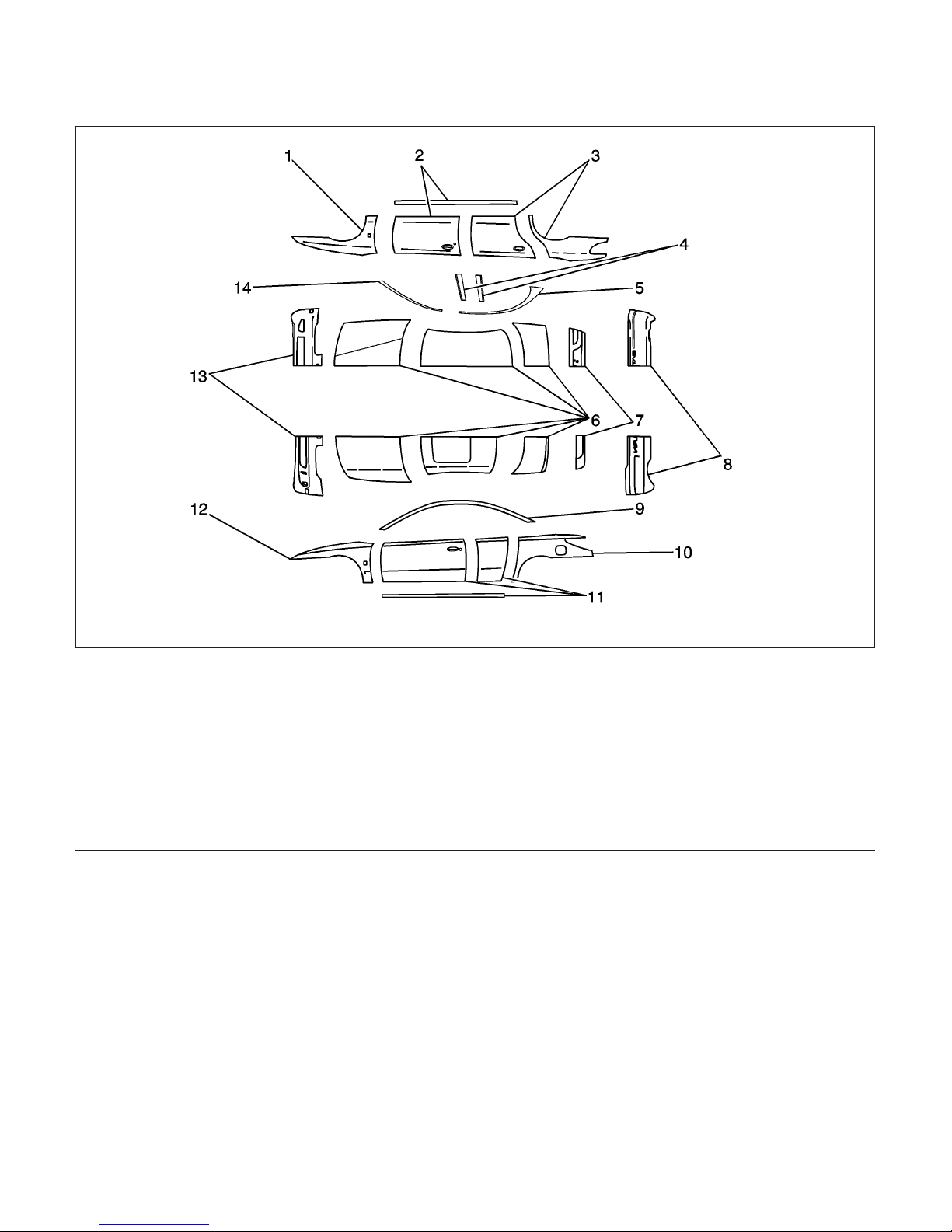
Panel Identification
Legend
(1) PA + PPE
(2) ABS + PC
(3) PA + PPE
(4) ABS + PC
(5) PET
(6) Steel
(7) ABS + PC
873924
(8) TPO
(9) PET
(10) PA + PPE
(11) ABS + PC
(12) PA + PPE
(13) TPO
(14) PET
3-2 2003 Saturn Ion
Exterior body panels are constructed of various
materials, due to the increased dent and corrosion
resistance of modern composites. All vertical panels,
such as fenders, doors, quarters, and rocker
panels, are made from rigid thermoplastic. Front and
rear fascias are constructed of thermoplastic
olefin (TPO). The hood, roof, and deck are steel.
Different materials require different procedures
for preparing and refinishing. Before beginning any
repair, identify the type of material involved.
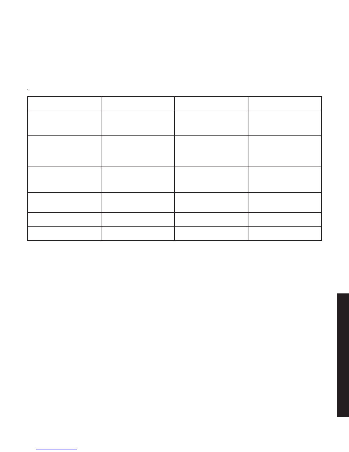
Panel Identification
Identifying Symbol
PE Polyethylene
PP Polypropylene
ABS Acrylonitrite/Butadine/Styrene
ABS+PC
E/P/TPO
PA + PPE
Chemical Composition or
Plastic “Family” Name
Acrylonitrite/Butadine-Styrene
+ Polycarbonate
Ethylene/Polypropylene
(Rubber)
Polyamide +
Polyphenylene Ether
Typical Area where Used Common or Trade Names
Inner Fender Panels,
Valances, Spoilers, Inner
Trim Panels, Seatbelt
Covers, Gas Tank Shields
Kick Panels, Deflector
Panels, Cowl Panels, Interior
Moldings, Radiator Shrouds,
Inner Fenders, Bumper
Covers
Instrument Clusters, Trim
Moldings, Consoles, Armrest
Supports, Steering Column
Jackets
Instrument Panels, Exterior
Door Panels, Rocker Panel
Covers
Bumper Covers
Fenders GTX
Dylan, Fortiflex, Marlex,
Alathon, Hi-Fax,
Hosalen, Paxon
Profax, Oleflo, Marlex, Azdel,
Novolen, Tenite, Daplen,
Escorene
ABS, Cycolac, Abson,
Kralastic, Lustran,
Absafil, Dyel
Babyland, Proloy,
Cycoloy, KHA
TPO, TPR (Thermoplastic
Rubber) EPI, EPII
2003 Saturn Ion
2003 Saturn Ion
3-3
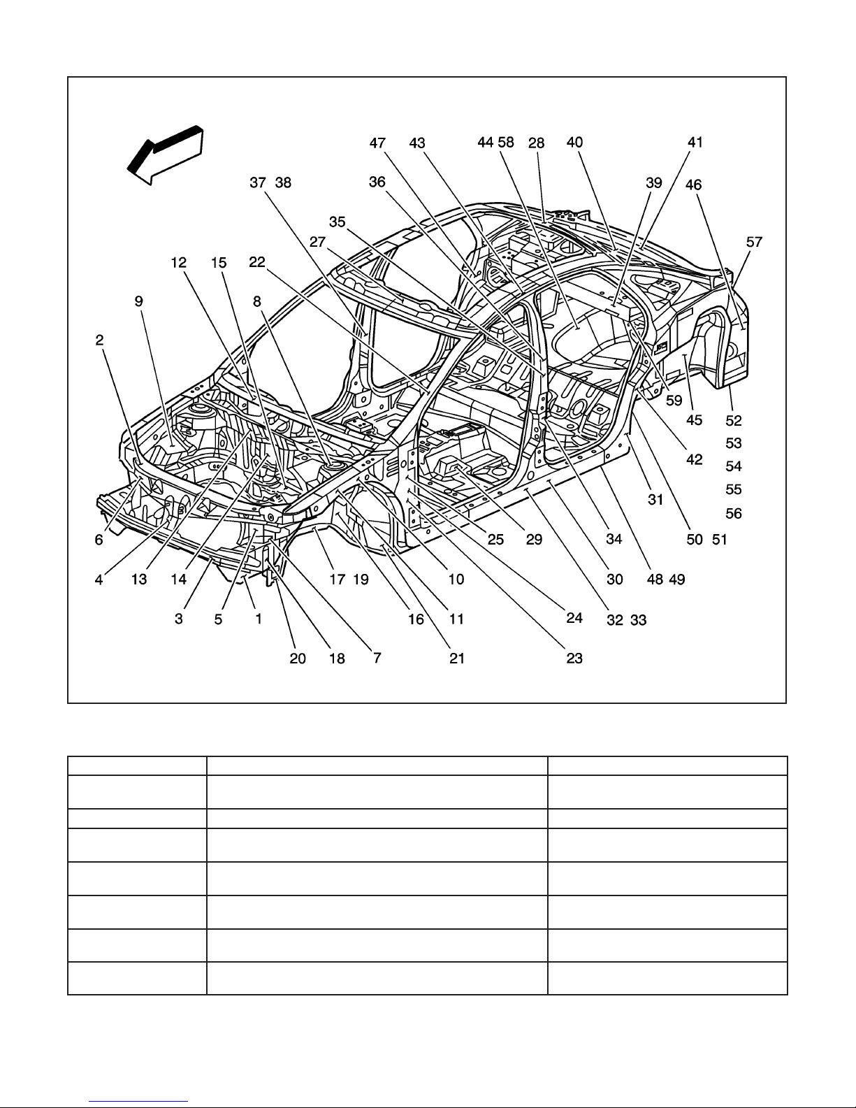
Structure Identification
Number Description Procedure
1
2 Tie Bar Replacement
3
4
5
6
7
Impact Bar Bracket Replacement – Front Bumper
Tie Bar Replacement – Lower
Latch Primary Support Replacement – Hood
Tie Bar Replacement – Left
Tie Bar Replacement – Right
Bracket Replacement Side Rail – Front Compartment
3-4 2003 Saturn Ion
867419
Structure Identification
Impact Bar Bracket Replacement -
Front Bumper on page 3-15
Tie Bar Replacement on page 3-17
Tie Bar Replacement - Lower on
page 3-21
Latch Primary Support Replacement -
Hood on page 3-26
Tie Bar Replacement - Left on
page 3-19
Tie Bar Replacement - Right on
page 3-23
Bracket Replacement Front
Compartment - Side Rail on page 3-30
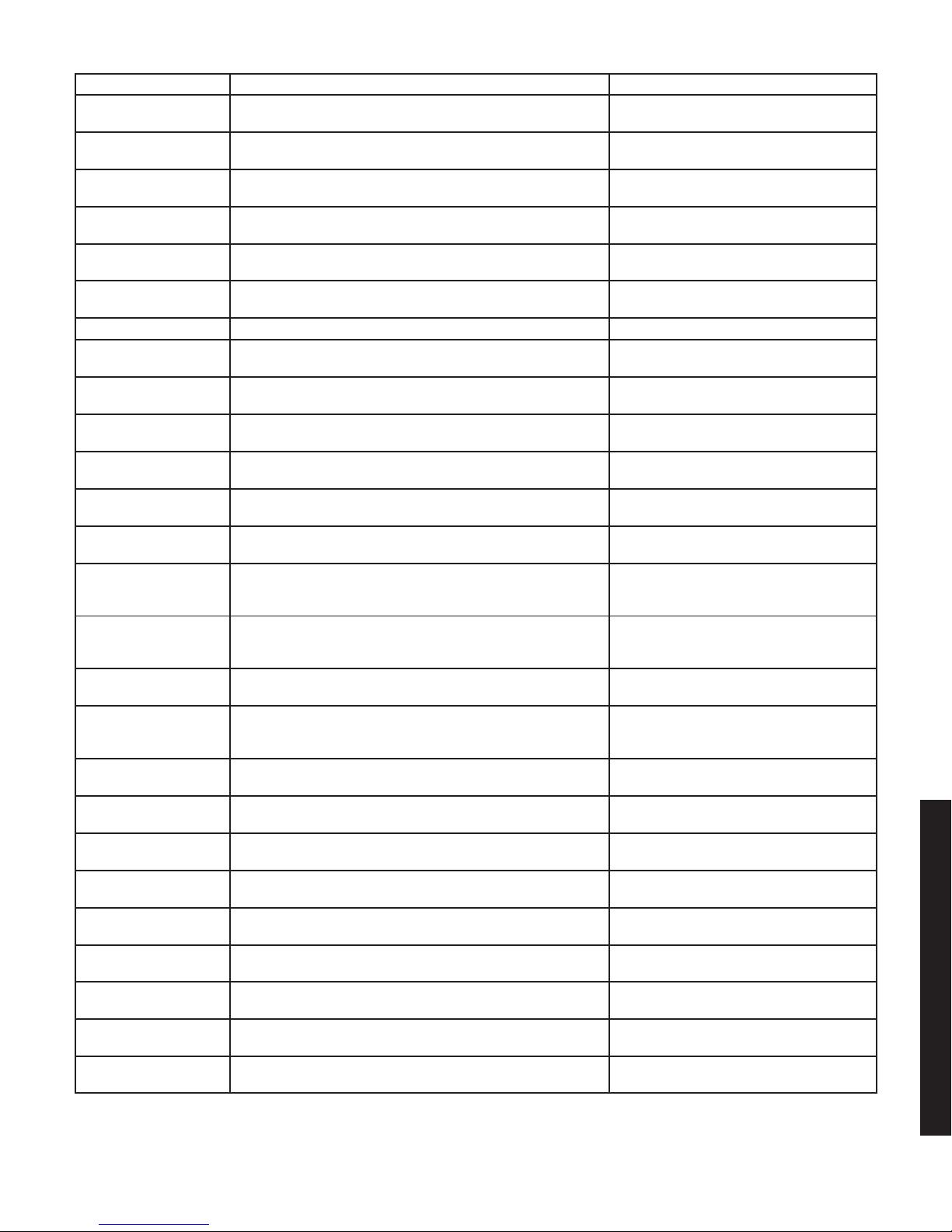
Structure Identification (cont’d)
Number Description Procedure
8
9
10
11
12
13
14 Dash Panel Replacement
15
16
17
18
19
20
21
22
23
24
25
26
27
28
29
30
31
32
33
Wheelhouse Replacement – Front
Wheelhouse Extension Replacement – Front
Rail Replacement Front Compartment – Side Upper
Rail Sectioning Front Compartment – Side Upper
Plenum Panel Replacement – Upper
Plenum Panel Replacement – Lower
Cross Bar New Replacement – Floor Panel
Rail Replacement Front Compartment – Front
Rail Replacement Front Compartment – Front Half
Rail Sectioning Front Compartment – Front
Rail Replacement Front Side Underbody – Outer
Suspension Support Replacement – Front
Extension Replacement Front Compartment
Side Rail – Rear
Windshield Frame Reinforcement Replacement –
Inner Upper
Hinge Pillar Body Replacement – Front Inner
Hinge Pillar Body Reinforcement Replacement –
Front Inner
Hinge Pillar Body Sectioning – Front
Roof Panel Replacement – Outer
Windshield Frame Header Panel Replacement – Front
Rear Window Frame Header Panel Replacement – Rear
Floor Panel Replacement – Center
Rocker Panel Replacement – Inner
Rocker Panel Extension Replacement – Inner
Rocker Panel Reinforcement Replacement – Inner
Rocker Panel Reinforcement Sectioning – Inner
Wheelhouse Replacement - Front on
page 3-32
Wheelhouse Extension Replacement -
Front on page 3-34
Rail Replacement Front Compartment -
Side Upper on page 3-36
Rail Sectioning Front Compartment -
Side Upper on page 3-39
Plenum Panel Replacement - Upper on
page 3-43
Plenum Panel Replacement - Lower on
page 3-45
Dash Panel Replacement on page 3-48
Cross Bar No.1 Replacement - Floor
Panel on page 3-51
Rail Replacement Front Compartment -
Front on page 3-53
Rail Replacement Front Compartment -
Front Half on page 3-55
Rail Sectioning Front Compartment -
Front on page 3-59
Rail Replacement Front Side
Underbody - Outer on page 3-63
Suspension Support Replacement -
Front on page 3-66
Extension Replacement Front
Compartment Side Rail - Rear on
page 3-68
Windshield Frame Reinforcement
Replacement - Inner Upper on
page 3-70
Hinge Pillar Body Replacement - Front
Inner on page 3-75
Hinge Pillar Body Reinforcement
Replacement - Front Inner on
page 3-73
Hinge Pillar Body Sectioning - Front on
page 3-78
Roof Panel Replacement - Outer on
page 3-81
Windshield Frame Header Panel
Replacement - Front on page 3-85
Rear Window Frame Header Panel
Replacement - Rear on page 3-87
Floor Panel Replacement - Center on
page 3-89
Rocker Panel Replacement - Inner on
page 3-93
Rocker Panel Extension Replacement -
Inner on page 3-95
Rocker Panel Reinforcement
Replacement - Inner on page 3-97
Rocker Panel Reinforcement Sectioning
- Inner on page 3-100
2003 Saturn Ion
2003 Saturn Ion
3-5

Structure Identification (cont’d)
Number Description Procedure
34
35
36
37
38
39
40
41
42
43
44
45
46
47
48
49
50
51
52
53
54
55
56
57
58
Pillar Lock Front Door Sectioning – Outer
Pillar Lock Front Door Reinforcement Replacement
– Outer
Pillar Lock Front Door Reinforcement
Pillar Lock Front Door Replacement – Inner
Pillar Lock Front Door Sectioning Replacement – Outer
Rear Window Reinforcement Replacement – Lower Front
Rear Window Panel Replacement
Rear Window Reinforcement – Rear
Pillar Lock Rear Door Replacement – Inner
Body Side Panel Replacement – Outer
Rear Compartment Floor Panel Sectioning
Wheelhouse Replacement – Rear Inner
Quarter Panel Sectioning – Outer
Quarter Panel Replacement – Inner
Cross Bar No. 4 Replacement – Floor Panel
Cross Bar No. 4 Extension Replacement – Floor Panel
Cross Bar No. 5 Replacement – Floor Panel Center
Cross Bar No. 5 Extension Replacement – Floor Panel
Rail Replacement Rear Side Underbody
Rail Sectioning Rear Side Underbody
Rail Side Underbody Gusset Replacement – Rear
Rail Side Underbody Reinforcement Replacement – Rear
Impact Bar Anchor Plate Replacement – Rear Bumper
Body Rear End Panel Replacement
Battery Tray Replacement
Pillar Lock Front Door Sectioning -
Outer on page 3-103
Pillar Lock Front Door Reinforcement
Replacement - Outer on page 3-107
Pillar Lock Front Door Reinforcement
Sectioning - Outer on page 3-109
Pillar Lock Front Door Replacement -
Inner on page 3-112
Pillar Lock Front Door Reinforcement
Sectioning - Outer on page 3-109
Rear Window Reinforcement
Replacement - Lower Front on
page 3-114
Rear Window Panel Replacement on
page 3-116
Rear Window Reinforcement
Replacement - Rear on page 3-119
Pillar Lock Rear Door Replacement -
Inner on page 3-121
Body Side Panel Replacement - Outer
on page 3-123
Rear Compartment Floor Panel
Sectioning on page 3-126
Wheelhouse Replacement - Rear Inner
on page 3-130
Quarter Panel Sectioning - Outer on
page 3-133
Quarter Panel Replacement - Inner on
page 3-136
Cross Bar No.4 Replacement - Floor
Panel on page 3-140
Cross Bar No.4 Extension Replacement
- Floor Panel on page 3-138
Cross Bar No.5 Replacement - Floor
Panel on page 3-145
Cross Bar No.5 Extension Replacement
- Floor Panel on page 3-143
Rail Replacement Rear Side
Underbody on page 3-147
Rail Sectioning Rear Side Underbody
on page 3-150
Rail Underbody Gusset Replacement -
Rear on page 3-155
Rail Underbody Reinforcement
Replacement - Rear on page 3-157
Impact Bar Anchor Plate Replacement -
Rear Bumper on page 3-160
Body Rear End Panel Replacement on
page 3-162
Battery Tray Replacement on
page 3-28
3-6 2003 Saturn Ion
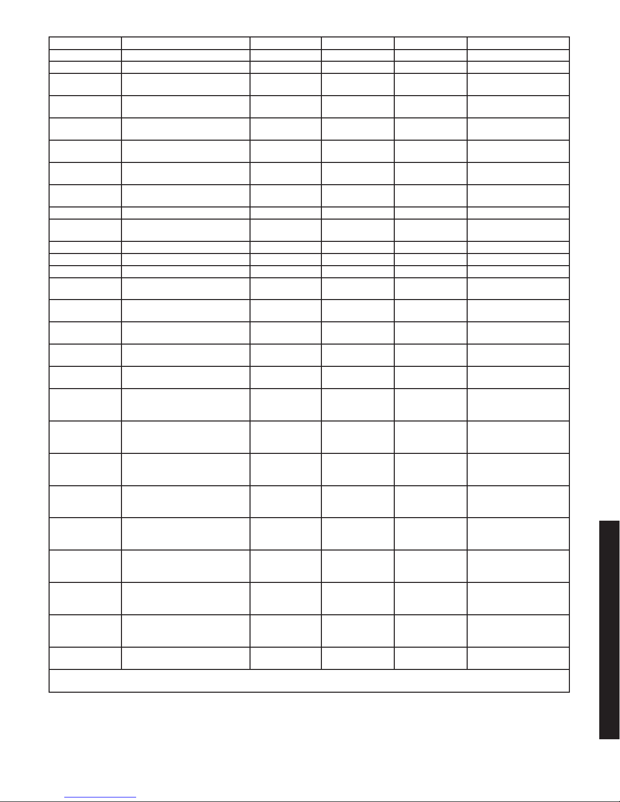
Specifications
Dimensions - Body
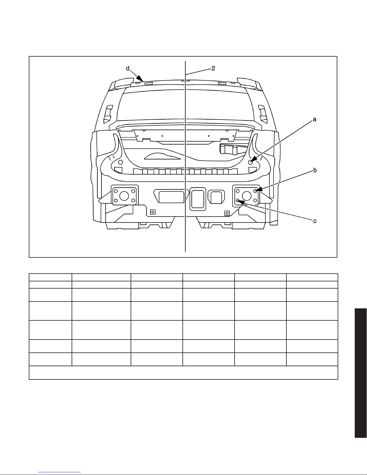
Rear End
Location Description Length = x Width = y Height = z Point to Point
2 Center Line — — — x
a
b
c
d (Sedan)
d (Coupe)
All dimensions are measured from a zero line, a center line, and a common datum. All dimensions are symmetrical unless
otherwise specified.
Rear Tail Lamp
Pocket Hole
Rear Impact Beam
Upper Outer
Attach Hole
Rear Impact Beam
Lower Outer
Attach Hole
Rear Header Panel
Roof Attachment Hole
Rear Header Panel
Roof Attachment Hole
5162 532 683 x
5149 587 447 x
5176 439 327 x
4133 306 1326 x
4068 306 1285 x
876934
2003 Saturn Ion
2003 Saturn Ion
3-7
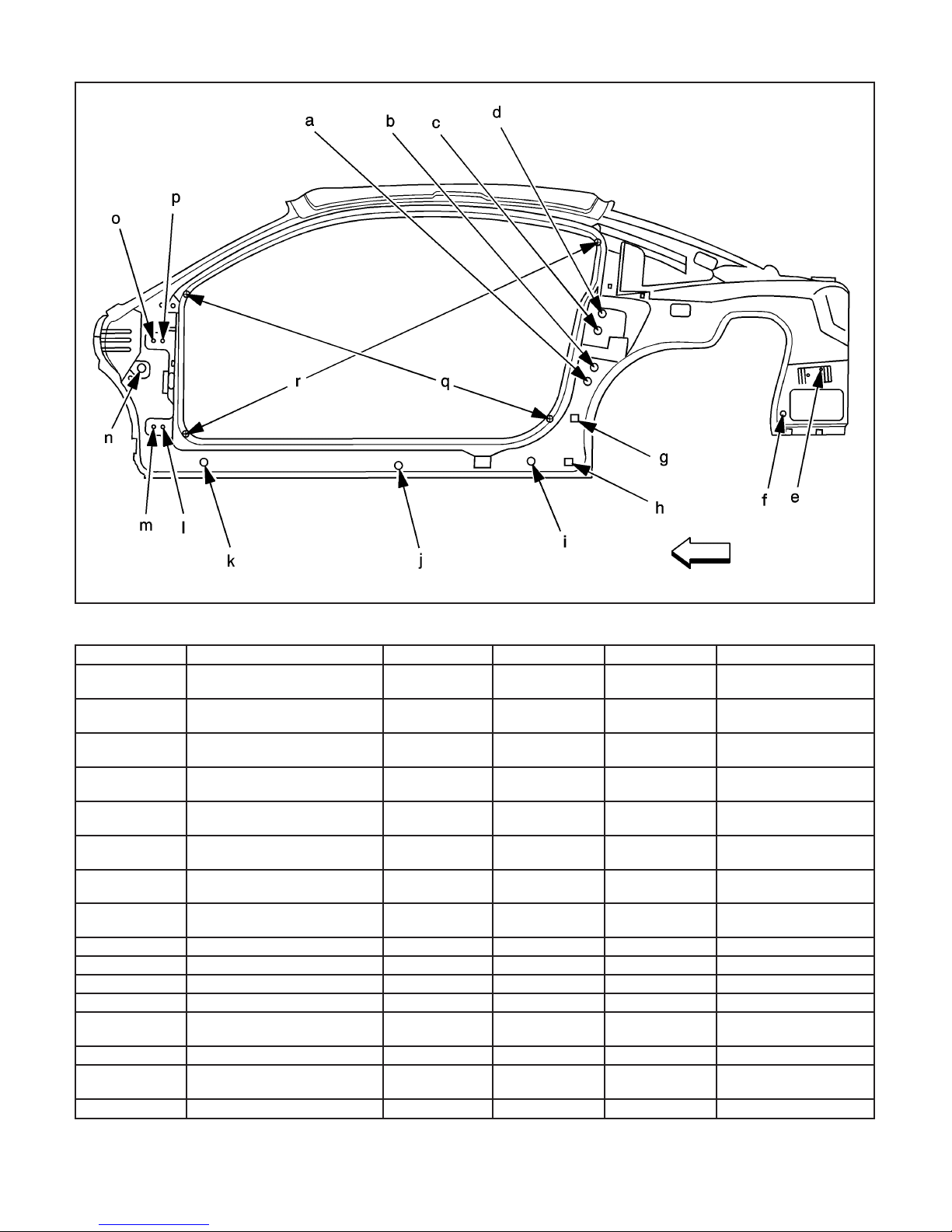
Coupe Side
Location Description Length = x Width = y Height = z Point to Point
a
b
c
d
e
f
g
h
i Rocker Panel Rear Hole 3780 762 250 x
j Rocker Panel Center Hole 3228 756 234 x
k Rocker Panel Front Hole 2432 762 250 x
l Front Lower Hinge Rear Hole 2260 750 396 x
m
n Body Side Control Hole 2175 745 640 x
o
p Front Upper Hinge Rear Hole 2260 739 754 x
Rear Lower Hinge
Lower Hole
Rear Lower Hinge
Upper Hole
Rear Upper Hinge
Lower Hole
Rear Upper Hinge
Upper Hole
Fascia Bracket Rear
Upper Hole
Quarter Panel Rear Inner
Lower Hole
Quarter Panel Dog Leg
Outer Attach Hole
Quarter Panel Dog Leg
Outer Attach Hole
Front Lower Hinge
Front Hole
Front Upper Hinge
Front Hole
3996 770 555 x
4046 759 649 x
4067 747 758 x
4056 738 863 x
4989 768 798 x
4822 730 445 x
3955 762 320 x
3961 762 235 x
2225 750 396 x
2225 739 754 x
876935
3-8 2003 Saturn Ion
Location Description Length = x Width = y Height = z Point to Point
q
r
All dimensions are measured from a zero line, a center line, and a common datum. All dimensions are symmetrical unless
otherwise specified.
Door Opening Point to Point
Measurement to Weld
Flange Die Marks
Door Opening Point to Point
Measurement to Weld
Flange Die Marks
x x x 1588
x x x 1868
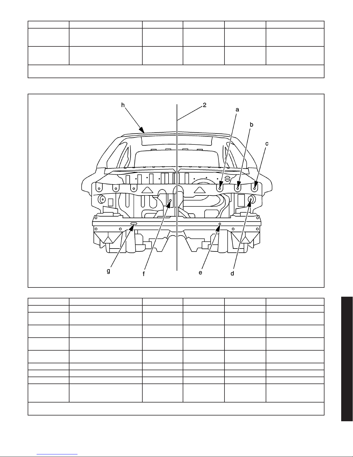
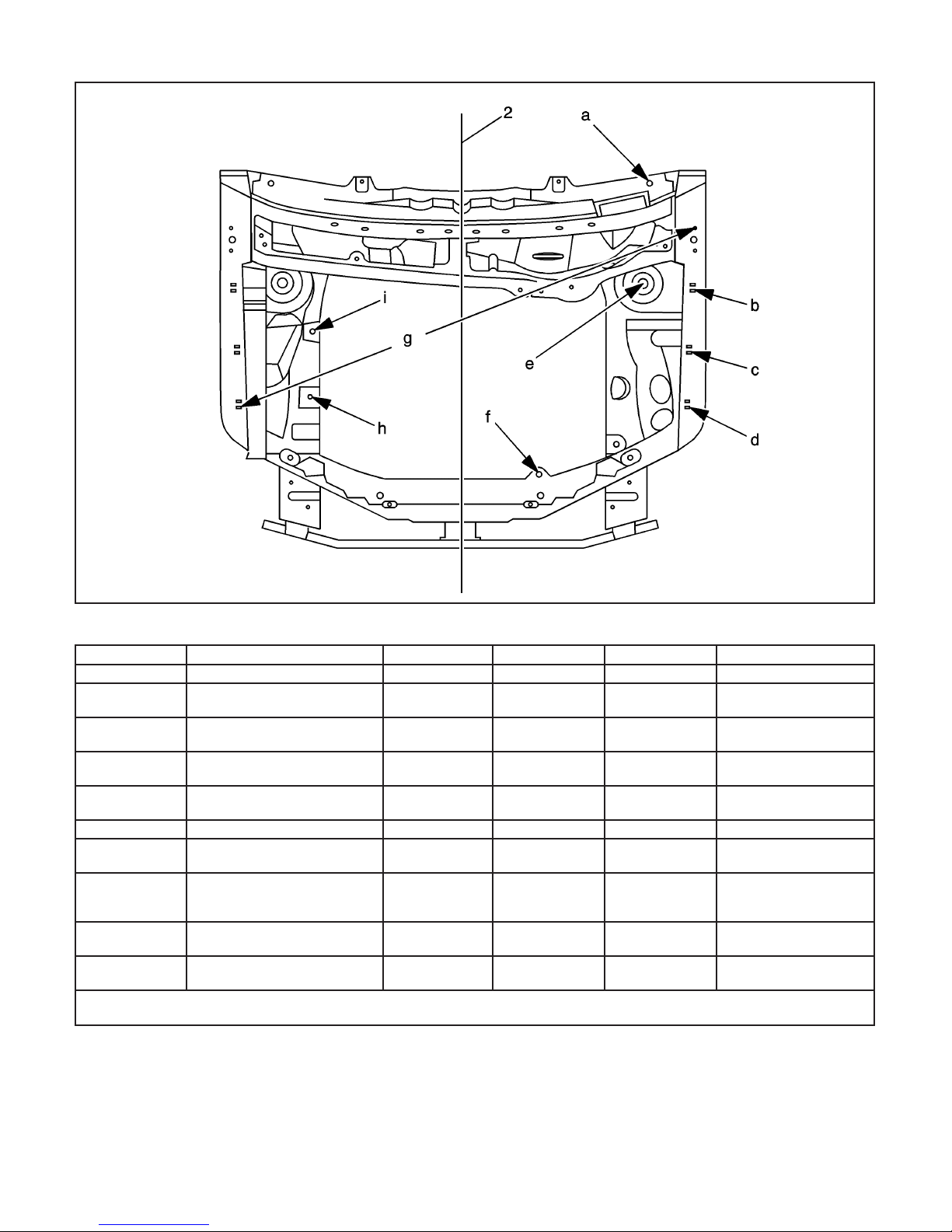
Front End
Location Description Length = x Width = y Height = z Point to Point
2 Center Line — — — x
a
b
c
d
e Lower Tie Bar Outer Hole 998 314 428 x
f Center Brace Hole 1089 17 568 x
g Lower Tie Outer Slot 998 314 428 x
h
All dimensions are measured from a zero line, a center line, and a common datum. All dimensions are symmetrical unless
otherwise specified.
Front Lamp Assembly Inner
Attach Hole
Front Lamp Assembly Center
Attach Hole
Front Lamp Assembly Outer
Attach Hole
Front Lamp Assembly Lower
Attach Hole
Front Header Panel Roof
Attachment Hole
(Sedan and Coupe)
1146 327 675 x
1208 458 682 x
1271 589 676 x
1307 561 594 x
2799 297 1307 x
2003 Saturn Ion
876936
2003 Saturn Ion
3-9
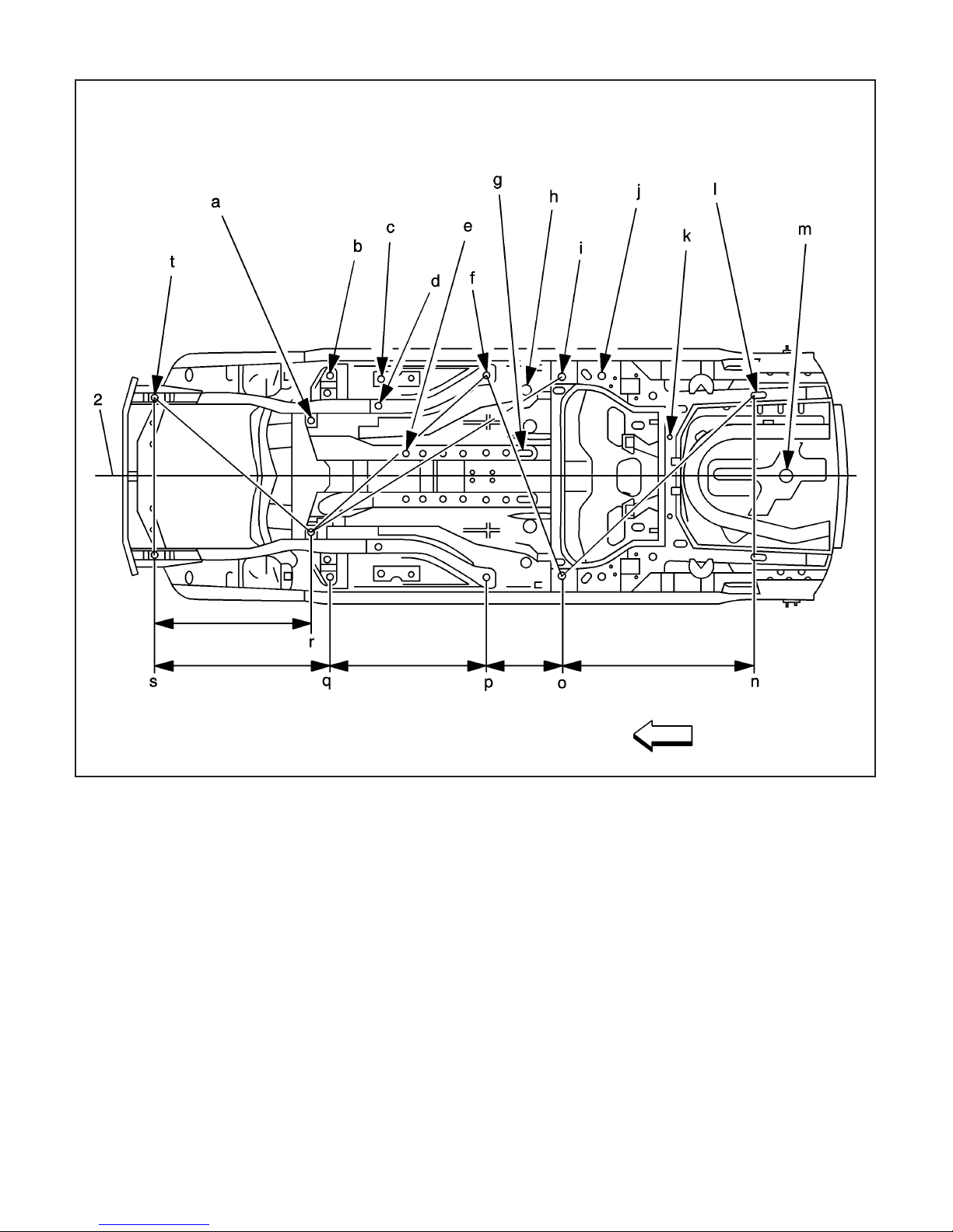
Underbody
3-10 2003 Saturn Ion
876938
Location Description Length = x Width = y Height = z Point to Point
2 Center Line — — — x
a Rear Cradle Attachment Hole 2100 332 201 x
b
c
d
e
f
g
h Floor Pan Rear Drain Hole 3378 521 190 x
i
j Front Rail Hole 3826 600 184 x
k 5 Bar Outer Hole 4235 180 354 x
l Rear Rail Rear Slot 4757 487 372 x
m
t
ntoo
otop
ptoq
qtos
rtos
stot
ttor
rtof
rtoi
ftoo
otol
lton
All dimensions are measured from a zero line, a center line, and a common datum. All dimensions are symmetrical unless
otherwise specified.
Front Rail Outer Torque Box
Master Gage Hole
Floor Pan Drain Hole
Front Hole
Front Rail Hole Front of Rear
Portion
Floor Pan Sled Rail
Front Hole
Front Rail Hole Rear of Rear
Portion
Floor Pan Sled Rail
Rear Hole
Rear Rail Torque Box Master
Gage Hole
Rear Compartment Floor
Pan Drain Hole
Front Cradle
Attachment Hole
Rear Rail Rear Hole to Rear
Rail Master Gage Hole
Rear Rail Master Gage Hole
to Front Rail Rear Hole
Front Rail Rear Hole to Front
Rail Master Gage Hole
Front Rail Master Gage Hole
to Front Cradle
Attachment Hole
Rear Cradle Attachment Hole
to Front Cradle
Attachment Hole
Front Cradle Attachment
Hole to Front Cradle
Attachment Hole
Front Cradle Attachment
Hole to Opposite Rear
Cradle Attachment
Rear Cradle Attachment Hole
to Opposite Rear Rail
Rear Hole
Rear Cradle Attachment Hole
to Rear Rail Master
Gage Hole
Front Rail Rear Hole to
Opposite Rear Rail Master
Gage Hole
Rear Rail Master Gage Hole
to Opposite Rear Rail
Rear Hole
Rear Rail Rear Hole to Rear
Rail Rear Hole
2218 600 121 x
2420 542 190 x
2675 421 134 x
2585 162 133 x
3171 601 167 x
3374 170 144 x
3593 592 203 x
5000 40 221 x
1371 474 231 x
— — — 1174
— — — 419
— — — 956
— — — 847
— — — 742
— — — 948
— — — 1087
— — — 1756
— — — 1756
— — — 1243
— — — 1591
— — — 974
2003 Saturn Ion
2003 Saturn Ion
3-11
Engine Compartment
Location Description Length = x Width = y Height = z Point to Point
2 Center Line — — — x
a
b
c
d
e Strut Tower Center Hole 1811 553 815 x
f
g
h
i
All dimensions are measured from a zero line, a center line, and a common datum. All dimensions are symmetrical unless
otherwise specified.
Upper Cowl Panel Rear
Flange Hole
Front Upper Rail Rear
Fender Attach
Front Upper Rail Center
Fender Attach
Front Upper Rail Front
Fender Attach
Front Upper Tie Bar Rear
Flange Hole
Point to Point Front Fender
Attach Hole to Rear Hinge
Attach Hole
Front Engine Mount Hole
Rail Surface Not Top of Stud
Rear Engine Mount Hole Rail
Surface Not Top of Stud
2115 590 873 x
1786 698 805 x
1594 688 773 x
1425 681 739 x
1226 232 700 x
— — — 1499
1461 470 515 x
1657 465 515 x
876940
3-12 2003 Saturn Ion
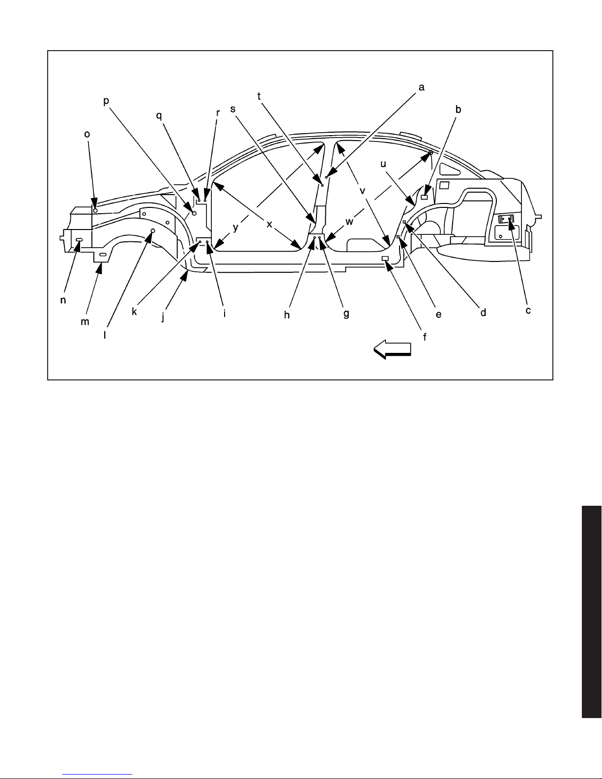
Sedan Side
876943
2003 Saturn Ion
2003 Saturn Ion
3-13

Location Description Length = x Width = y Height = z Point to Point
a
b
c
d
e
f
g Rear Lower Hinge Rear Hole 3289 746 430 x
h Rear Lower Hinge Front Hole 3254 747 430 x
i Front Lower Hinge Rear Hole 2259 748 396 x
j Rear Cradle Attachment Hole 2100 332 201 x
k
l Front Rail Outer Panel Hole 1840 463 430 x
m
n
o
p Body Side Control Hole 2175 745 640 x
q
r Front Upper Hinge Rear Hole 2260 737 754 x
s
t
u
v
w
x
y
All dimensions are measured from a zero line, a center line, and a common datum. All dimensions are symmetrical unless
otherwise specified.
Rear Upper Hinge
Upper Hole
Quarter Panel Dog Leg
Outer Attachment Hole
Fascia Bracket Rear
Upper Hole
Quarter Panel Dog Leg
Outer Attach Hole
Quarter Panel Dog Leg
Outer Attachment Hole
Quarter Panel Dog Leg
Outer Attachment Hole
Front Lower Hinge
Front Hole
Front Cradle
Attachment Hole
Weld Nut Hole Washer Bottle
Attachment
Front Upper Outer Rail
Front Hole
Front Upper Hinge
Front Hole
Front Door Latch Striker
Upper Hole
Rear Upper Hinge
Lower Hole
Rear Latch Striker
Upper Hole
Rear Door Opening Point to
Point Measurements to Weld
Flange Die Marks
Rear Door Opening Point to
Point Measurement to Weld
Flange Die Marks
Front Door Opening Point to
Point Measurement to Weld
Flange Die Marks
Front Door Opening Point to
Point Measurement to Weld
Flange Die Marks
3301 746 776 x
4226 779 768 x
4974 746 596 x
4068 767 617 x
3991 767 437 x
3780 762 250 x
2225 740 396 x
1371 500 280 x
1222 540 409 x
1880 743 760 x
2224 737 754 x
3263 748 574 x
3299 754 741 x
4145 739 736 x
— — — 1015
— — — 1188
— — — 970
— — — 1337
3-14 2003 Saturn Ion
Repair Instructions
Impact Bar Bracket Replacement - Front
Bumper
Removal Procedure
Caution: To avoid personal injury when exposed
to welding flashes or to galvanized (Zinc Oxide)
metal toxic fumes while grinding/cutting on
any type of metal or sheet molded compound, you
must work in a properly ventilated area, wearing
an approved respirator, eye protection, earplugs,
welding gloves, and protective clothing.
1. Disable the SIR system.
2. Disconnect the negative battery cable.
3. Remove all related panels and components.
4. Repair as much of the damage as possible. Refer
to
Dimensions - Body on page 3-7
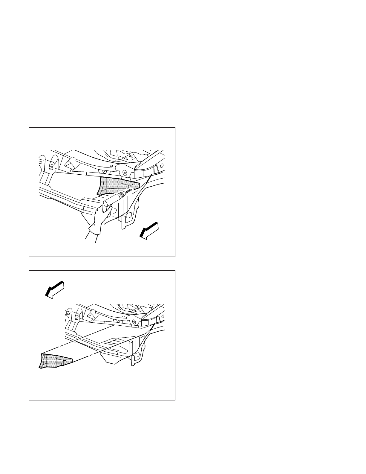
5. Remove the sealers and anti-corrosion materials
from the repair area, as necessary.
Important: Note the number and location of the
factory welds for installation of the impact bar bracket
- front bumper
6. Locate and drill out all the factory welds from the
outside surface of the rail.
.
868868
2003 Saturn Ion
867608
2003 Saturn Ion
3-15

867609
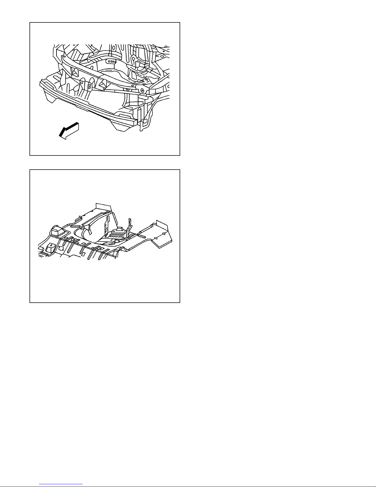
7. Remove the front bumper impact bar bracket.
Installation Procedure
1. Prepare all mating surfaces as necessary.
2. Apply 3M Weld-Thru Coating P/N 05916 or
equivalent to all mating surfaces.
3-16 2003 Saturn Ion
867597
Important: Verify the location of the front rail using
3-dimensional measuring equipment.
3. Position the impact bar bracket on the rail and
clamp in place.
867609

4. Plug weld accordingly.
5. Clean and prepare all of the welded surfaces.
6. Install all of the related panels and components.
7. Apply the sealers and anti-corrosion materials
to the repair area, as necessary.
8. Paint the repaired area.
9. Connect the negative battery cable.
10. Enable the SIR system.
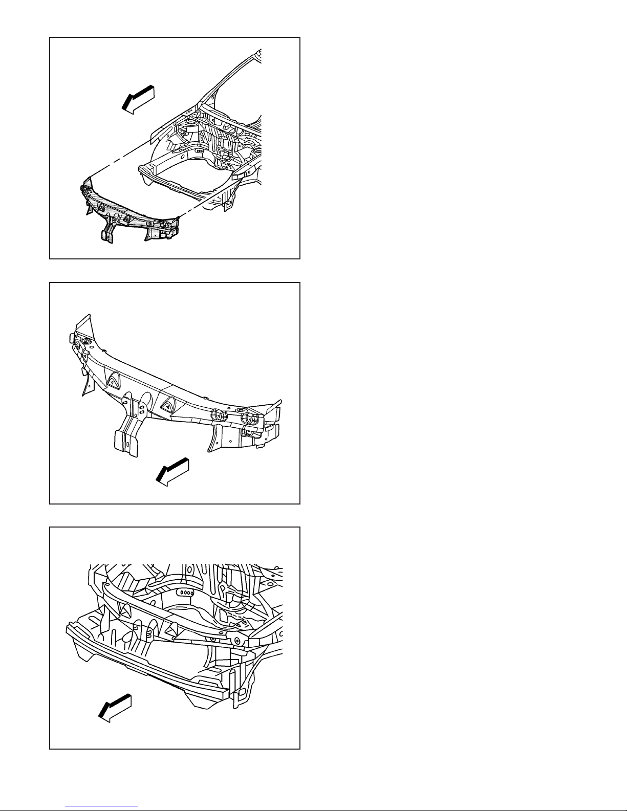
Tie Bar Replacement
Removal Procedure
Caution: To avoid personal injury when exposed
to welding flashes or to galvanized (Zinc Oxide)
metal toxic fumes while grinding/cutting on
any type of metal or sheet molded compound, you
must work in a properly ventilated area, wearing
an approved respirator, eye protection, earplugs,
welding gloves, and protective clothing.
1. Disable the SIR system.
2. Disconnect the negative battery cable.
3. Remove all related panels and components.
4. Repair as much of the damage as possible to
factory specifications. Refer to
Body on page 3-7
.
5. Note the location and remove the sealers and
anti-corrosion materials from the repair area, as
necessary.
Important: Do not damage any inner panels or
reinforcements.
6. Locate and drill out all factory welds. Note the
number and location of the welds for installation
of the tie bar.
Dimensions -
868868
867423
2003 Saturn Ion
2003 Saturn Ion
867488
3-17
867491
7. Remove the damaged tie bar.
Installation Procedure
Important: If the location of the original plug weld
holes can not be determined, space the plug
weld holes every 40 mm (1 1/2 in) apart.
1. Drill 8 mm (5/16 in) plug weld holes in the service
part as necessary in the locations noted from the
original panel.
2. Prepare all mating surfaces as necessary.
3. Apply 3M Weld-Thru Coating P/N 05916 or
equivalent to all mating surfaces.
3-18 2003 Saturn Ion
865271
4. Position the tie bar to the vehicle using
3-dimensional measuring equipment. Clamp the
tie bar into place.
5. Plug weld accordingly.
6. Clean and prepare all welded surfaces.
7. Apply the sealers and anti-corrosion materials to
the repair area, as necessary.
8. Paint the repair area.
9. Install all related panels and components.
10. Connect the negative battery cable.
11. Enable the SIR system.
867423
Tie Bar Replacement - Left
Removal Procedure
Caution: To avoid personal injury when exposed
to welding flashes or to galvanized (Zinc Oxide)
metal toxic fumes while grinding/cutting on
any type of metal or sheet molded compound, you
must work in a properly ventilated area, wearing
an approved respirator, eye protection, earplugs,
welding gloves, and protective clothing.
Caution: When performing service on or near the
SIR components or the SIR wiring, the SIR
system must be disabled. Refer to SIR Disabling
and Enabling Zones. Failure to observe the correct
procedure could cause deployment of the SIR
components, personal injury, or unnecessary SIR
system repairs.
1. Disable the SIR system.
Caution: Before servicing any electrical
component, the ignition key must be in the OFF or
LOCK position and all electrical loads must be
OFF, unless instructed otherwise in these
procedures. If a tool or equipment could easily
come in contact with a live exposed electrical
terminal, also disconnect the negative battery
cable. Failure to follow these precautions
may cause personal injury and/or damage to the
vehicle or its components.
2. Disconnect the negative battery cable.
3. Remove all related panels and components.
4. Repair as much of the damage as possible. Refer
Dimensions - Body on page 3-7
to
5. Remove the sealers and anti-corrosion materials
from the repair area, as necessary.
Important: Note the number and location of the
factory welds for installation of the tie bar-left.
6. Locate and drill out all the necessary
factory welds.
.
867423
2003 Saturn Ion
867500
3-19
2003 Saturn Ion

867504
7. Remove the left tie bar.
Installation Procedure
Important: If the location of the original plug weld
holes can not be determined, space the plug
weld holes every 40 mm (1 1/2 in) apart.
1. Drill 8 mm (5/16 in) plug weld holes in the service
part as necessary in the locations noted from the
original panel.
2. Prepare all mating surfaces as necessary.
3. Apply 3M Weld-Thru Coating P/N 05916 or
equivalent to all mating surfaces.
3-20 2003 Saturn Ion
865272
4. Position the left tie bar to the vehicle using
3-dimensional measuring equipment. Clamp the
tie bar in place.
867504
5. Plug weld accordingly.
6. Clean and prepare all of the welded surfaces.
7. Install all of the related panels and components.
8. Apply the sealers and anti-corrosion materials
to the repair area, as necessary.
9. Paint the repaired area.
10. Connect the negative battery cable.
11. Enable the SIR system.
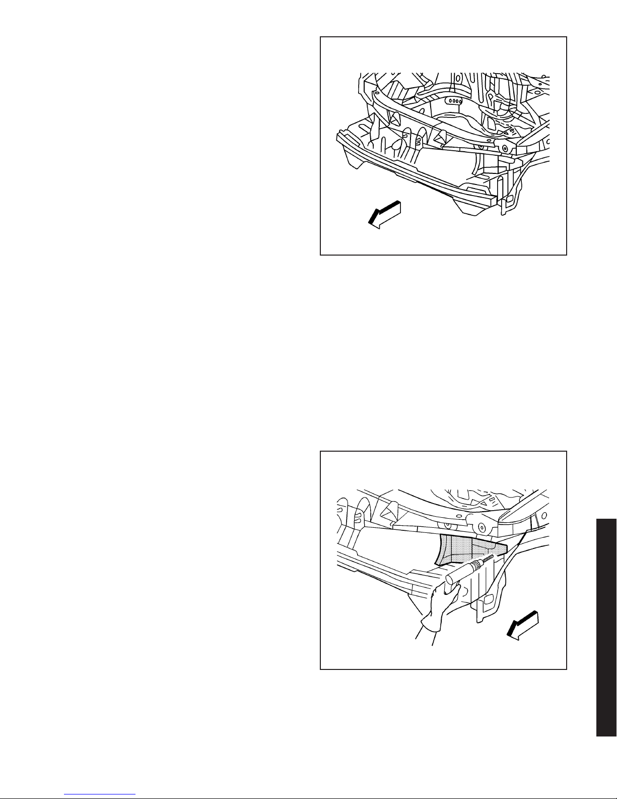
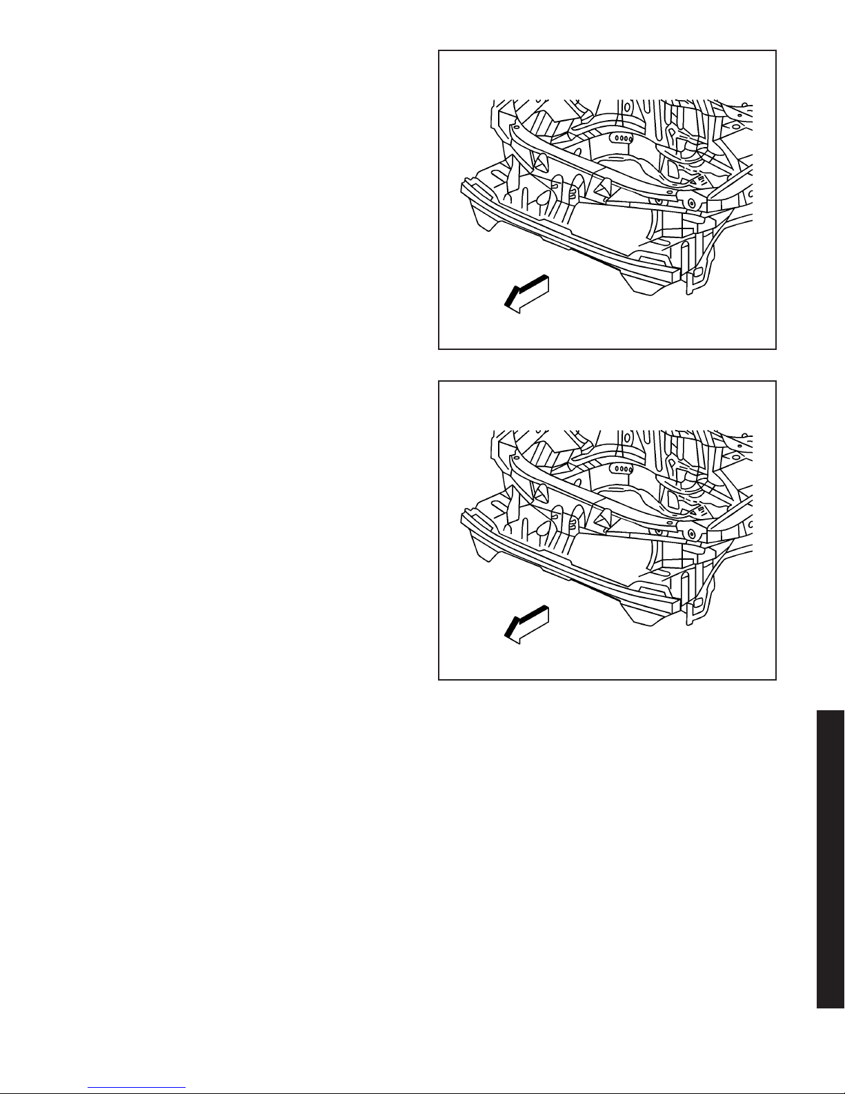
Tie Bar Replacement - Lower
Removal Procedure
Caution: To avoid personal injury when exposed
to welding flashes or to galvanized (Zinc Oxide)
metal toxic fumes while grinding/cutting on
any type of metal or sheet molded compound, you
must work in a properly ventilated area, wearing
an approved respirator, eye protection, earplugs,
welding gloves, and protective clothing.
Caution: When performing service on or near the
SIR components or the SIR wiring, the SIR
system must be disabled. Refer to SIR Disabling
and Enabling Zones. Failure to observe the correct
procedure could cause deployment of the SIR
components, personal injury, or unnecessary SIR
system repairs.
1. Disable the SIR system.
Caution: Before servicing any electrical
component, the ignition key must be in the OFF or
LOCK position and all electrical loads must be
OFF, unless instructed otherwise in these
procedures. If a tool or equipment could easily
come in contact with a live exposed electrical
terminal, also disconnect the negative battery
cable. Failure to follow these precautions
may cause personal injury and/or damage to the
vehicle or its components.
2. Disconnect the negative battery cable.
Important: This panel is replaced at factory seams or
can be unbolted for removal.
3. Remove all related panels and components.
4. Repair as much of the damage as possible. Refer
Dimensions - Body on page 3-7
to
5. Remove the sealers and anti-corrosion materials
from the repair area, as necessary.
.
867423
867423
2003 Saturn Ion
2003 Saturn Ion
3-21

867424
Important: Note the number and location of the
factory welds for installation of the lower tie bar.
6. Locate and drill out all the necessary
factory welds.
7. Remove the lower tie bar.
3-22 2003 Saturn Ion
867470
Installation Procedure
Important: If the location of the original plug weld
holes can not be determined, space the plug
weld holes every 40 mm (1 1/2 in) apart.
1. Drill 8 mm (5/16 in) plug weld holes in the service
part as necessary in the locations noted from the
original panel.
2. Prepare all mating surfaces as necessary.
3. Apply 3M Weld-Thru Coating P/N 05916 or
equivalent to all mating surfaces.
865257
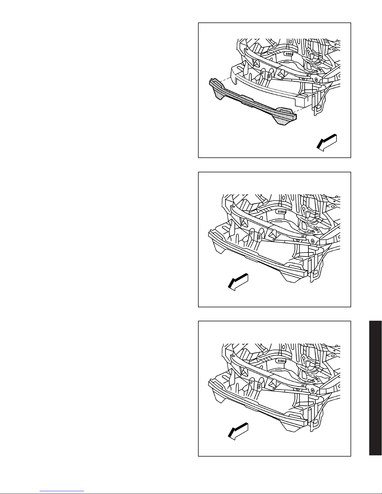
4. Position the tie bar on the vehicle using
3-dimensionial measuring equipment. Clamp the
tie bar into place.
5. Plug weld accordingly.
6. Clean and prepare all of the welded surfaces.
7. Install all of the related panels and components.
8. Apply the sealers and anti-corrosion materials
to the repair area, as necessary.
9. Paint the repaired area.
10. Connect the negative battery cable.
11. Enable the SIR system.
867470
Tie Bar Replacement - Right
Removal Procedure
Caution: To avoid personal injury when exposed
to welding flashes or to galvanized (Zinc Oxide)
metal toxic fumes while grinding/cutting on
any type of metal or sheet molded compound, you
must work in a properly ventilated area, wearing
an approved respirator, eye protection, earplugs,
welding gloves, and protective clothing.
Caution: Refer to SIR Caution on page 1-1 in
General Information.
Important: The graphic shows the left hand procedure.
The right hand procedure is similar.
1. Disable the SIR system.
2003 Saturn Ion
867423
2003 Saturn Ion
867423
3-23
Caution: Before servicing any electrical
component, the ignition key must be in the OFF or
LOCK position and all electrical loads must be
OFF, unless instructed otherwise in these
procedures. If a tool or equipment could easily
come in contact with a live exposed electrical
terminal, also disconnect the negative battery
cable. Failure to follow these precautions
may cause personal injury and/or damage to the
vehicle or its components.
2. Disconnect the negative battery cable.
3. Remove all related panels and components.
4. Repair as much of the damage as possible. Refer
Dimensions - Body on page 3-7
to
.
5. Remove the sealers and anti-corrosion materials
from the repair area, as necessary.
Important: Note the number and location of the
factory welds for installation of the right tie bar.
6. Locate and drill out all the necessary
factory welds.
867500
867504
7. Remove the right tie bar panel from the vehicle.
3-24 2003 Saturn Ion

Installation Procedure
Important: If the location of the original plug weld
holes can not be determined, space the plug
weld holes every 40 mm (1 1/2 in) apart.
1. Drill 8 mm (5/16 in) plug weld holes in the service
part as necessary in the locations noted from the
original panel.
2. Prepare all mating surfaces as necessary.
3. Apply 3M Weld-Thru Coating P/N 05916 or
equivalent to all mating surfaces.
4. Position the right tie bar panel to the vehicle using
3-dimensional measuring equipment. Clamp the
tie bar in place.
865272
5. Plug weld accordingly.
6. Clean and prepare all of the welded surfaces.
7. Install all of the related panels and components.
8. Apply the sealers and anti-corrosion materials
to the repair area, as necessary.
9. Paint the repaired area.
10. Connect the negative battery cable.
11. Enable the SIR system.
2003 Saturn Ion
867504
2003 Saturn Ion
867423
3-25

867423
Latch Primary Support
Replacement - Hood
Removal Procedure
Caution: To avoid personal injury when exposed
to welding flashes or to galvanized (Zinc Oxide)
metal toxic fumes while grinding/cutting on
any type of metal or sheet molded compound, you
must work in a properly ventilated area, wearing
an approved respirator, eye protection, earplugs,
welding gloves, and protective clothing.
Caution: When performing service on or near the
SIR components or the SIR wiring, the SIR
system must be disabled. Refer to SIR Disabling
and Enabling Zones. Failure to observe the correct
procedure could cause deployment of the SIR
components, personal injury, or unnecessary SIR
system repairs.
1. Disable the SIR system.
Caution: Before servicing any electrical
component, the ignition key must be in the OFF or
LOCK position and all electrical loads must be
OFF, unless instructed otherwise in these
procedures. If a tool or equipment could easily
come in contact with a live exposed electrical
terminal, also disconnect the negative battery
cable. Failure to follow these precautions
may cause personal injury and/or damage to the
vehicle or its components.
2. Disconnect the negative battery cable.
3. Remove all related panels and components.
4. Repair as much of the damage as possible. Refer
Dimensions - Body on page 3-7
to
5. Remove the sealers and anti-corrosion materials
from the repair area, as necessary.
Important: Note the number and location of the
factory welds for installation of the latch primary
support.
6. Locate and drill out all the necessary
factory welds.
.
3-26 2003 Saturn Ion
867511

7. Remove the latch primary support.
Installation Procedure
Important: If the location of the original plug weld
holes can not be determined, space the plug
weld holes every 40 mm (1 1/2 in) apart.
1. Drill 8 mm (5/16 in) plug weld holes in the service
part as necessary in the locations noted from the
original panel.
2. Prepare all mating surfaces as necessary.
3. Apply 3M Weld-Thru Coating P/N 05916 or
equivalent to all mating surfaces.
867514
4. Position the latch primary support on the vehicle
using 3-dimensional measuring equipment. Clamp
the support into place.
2003 Saturn Ion
865273
2003 Saturn Ion
867514
3-27
867423
872730
5. Plug weld accordingly.
6. Clean and prepare all of the welded surfaces.
7. Install all of the related panels and components.
8. Apply the sealers and anti-corrosion materials
to the repair area, as necessary.
9. Paint the repaired area.
10. Connect the negative battery cable.
11. Enable the SIR system.
Battery Tray Replacement
Removal Procedure
Caution: To avoid personal injury when exposed
to welding flashes or to galvanized (Zinc Oxide)
metal toxic fumes while grinding/cutting on
any type of metal or sheet molded compound, you
must work in a properly ventilated area, wearing
an approved respirator, eye protection, earplugs,
welding gloves, and protective clothing.
Caution: When performing service on or near the
SIR components or the SIR wiring, the SIR
system must be disabled. Refer to SIR Disabling
and Enabling Zones. Failure to observe the correct
procedure could cause deployment of the SIR
components, personal injury, or unnecessary SIR
system repairs.
1. Disable the SIR system.
Caution: Before servicing any electrical
component, the ignition key must be in the OFF or
LOCK position and all electrical loads must be
OFF, unless instructed otherwise in these
procedures. If a tool or equipment could easily
come in contact with a live exposed electrical
terminal, also disconnect the negative battery
cable. Failure to follow these precautions
may cause personal injury and/or damage to the
vehicle or its components.
2. Disconnect the negative battery cable.
Important: This panel is replaced at factory seams.
3. Remove all related panels and components.
4. Repair as much of the damaged area as possible.
Refer to
5. Remove the sealers and anti-corrosion materials
from the repair area, as necessary.
Dimensions - Body on page 3-7
.
3-28 2003 Saturn Ion

Important: Note the number and location of the
factory welds for installation of the battery tray.
6. Locate and drill out all the necessary
factory welds.
7. Remove the battery tray.
Installation Procedure
Important: If the location of the original plug weld
holes can not be determined, space the plug
weld holes every 40 mm (1 1/2 in) apart.
1. Drill 8 mm (5/16 in) plug weld holes in the service
part as necessary in the locations noted from the
original panel.
2. Prepare all mating surfaces for welding as
necessary.
3. Apply 3M Weld-Thru Coating P/N 05916 or
equivalent to all mating surfaces.
4. Position the battery tray to the vehicle. Clamp the
battery tray in place.
872732
5. Plug weld accordingly.
6. Clean and prepare all of the welded surfaces.
7. Install all of the related panels and components.
8. Apply the sealers and anti-corrosion materials
to the repair area, as necessary.
9. Paint the repaired area.
10. Connect the negative battery cable.
11. Enable the SIR system.
2003 Saturn Ion
872732
2003 Saturn Ion
872730
3-29

867612
Bracket Replacement Front Compartment
- Side Rail
Removal Procedure
Caution: To avoid personal injury when exposed
to welding flashes or to galvanized (Zinc Oxide)
metal toxic fumes while grinding/cutting on
any type of metal or sheet molded compound, you
must work in a properly ventilated area, wearing
an approved respirator, eye protection, earplugs,
welding gloves, and protective clothing.
Caution: When performing service on or near the
SIR components or the SIR wiring, the SIR
system must be disabled. Refer to SIR Disabling
and Enabling Zones. Failure to observe the correct
procedure could cause deployment of the SIR
components, personal injury, or unnecessary SIR
system repairs.
1. Disable the SIR system.
Caution: Before servicing any electrical
component, the ignition key must be in the OFF or
LOCK position and all electrical loads must be
OFF, unless instructed otherwise in these
procedures. If a tool or equipment could easily
come in contact with a live exposed electrical
terminal, also disconnect the negative battery
cable. Failure to follow these precautions
may cause personal injury and/or damage to the
vehicle or its components.
2. Disconnect the negative battery cable.
3. Remove all related panels and components.
4. Repair as much of the damage as possible. Refer
Dimensions - Body on page 3-7
to
5. Remove the sealers and anti-corrosion materials
from the repair area, as necessary.
Important: Note the number and location of the
factory welds for installation of the bracket side
rail-front compartment.
6. Locate and drill out all the necessary
factory welds.
.
3-30 2003 Saturn Ion
867617

7. Remove the side rail bracket from the front
compartment lower rail.
Installation Procedure
Important: If the location of the original plug weld
holes can not be determined, space the plug
weld holes every 40 mm (1 1/2 in) apart.
1. Drill 8 mm (5/16 in) plug weld holes in the service
part as necessary in the locations noted from the
original panel.
2. Prepare all mating surfaces as necessary.
3. Apply 3M Weld-Thru Coating P/N 05916 or
equivalent to all mating surfaces.
867618
4. Position the side rail bracket to the front
compartment lower rail and tie bar side panel.
Clamp the bracket in place.
2003 Saturn Ion
865267
2003 Saturn Ion
867618
3-31

867612
5. Plug weld accordingly.
6. Clean and prepare all of the welded surfaces.
7. Install all of the related panels and components.
8. Apply the sealers and anti-corrosion materials
to the repair area, as necessary.
9. Paint the repaired area.
10. Connect the negative battery cable.
11. Enable the SIR system.
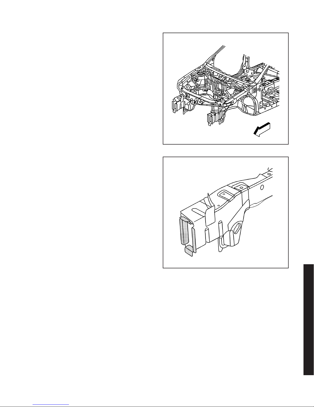
Wheelhouse Replacement - Front
Removal Procedure
Caution: To avoid personal injury when exposed
to welding flashes or to galvanized (Zinc Oxide)
metal toxic fumes while grinding/cutting on
any type of metal or sheet molded compound, you
must work in a properly ventilated area, wearing
an approved respirator, eye protection, earplugs,
welding gloves, and protective clothing.
Caution: When performing service on or near the
SIR components or the SIR wiring, the SIR
system must be disabled. Refer to SIR Disabling
and Enabling Zones. Failure to observe the correct
procedure could cause deployment of the SIR
components, personal injury, or unnecessary SIR
system repairs.
1. Disable the SIR system.
2. Disconnect the negative battery cable.
Important: The upper strut mounting surface is a
dimensionally critical area, and 3-dimensional
measuring equipment should be used to locate the
front wheelhouse assembly. The front wheelhouse can
be serviced as a complete assembly for both the
left and right wheelhouses. A wheelhouse front panel
is also available to service separately on the left or
the right sides.
3. Remove the sealers and anti-corrosion materials
from the repair area, as necessary.
Important: Be sure to inspect the front of the cowl
and dash panel for damage. If the metal surface
is damaged, the cowl panel must be repaired to restore
the structural integrity of the vehicle.
4. Visually inspect the damaged area. Repair as
much of the damage as possible. Refer to
Dimensions - Body on page 3-7
.
3-32 2003 Saturn Ion
867478

5. Locate and drill out all factory welds.
Important: Note the number and location of welds for
installation of the front wheelhouse.
6. Remove the front wheelhouse from the vehicle.
867495
Installation Procedure
Important: If the location of the original plug weld
holes can not be determined, space the plug
weld holes every 40 mm (1 1/2 in) apart.
1. Drill 8 mm (5/16 in) plug weld holes as necessary
in the locations noted from the original assembly.
2. Prepare the mating surfaces as necessary.
3. Apply 3M Weld-Thru Coating P/N 05916 or
equivalent to all mating surfaces.
4. Position the front wheelhouse in the vehicle using
3-dimensional measuring equipment. Clamp the
wheelhouse in place.
2003 Saturn Ion
867507
2003 Saturn Ion
865277
3-33

867495
868716
5. Plug weld accordingly.
6. Clean and prepare all of the welded surfaces.
7. Install all related panels and components.
8. Apply the sealers and anti-corrosion materials to
the repair area, as necessary.
9. Paint the repaired area.
10. Connect the negative battery cable.
11. Enable the SIR system.
Wheelhouse Extension
Replacement - Front
Removal Procedure
Caution: To avoid personal injury when exposed
to welding flashes or to galvanized (Zinc Oxide)
metal toxic fumes while grinding/cutting on
any type of metal or sheet molded compound, you
must work in a properly ventilated area, wearing
an approved respirator, eye protection, earplugs,
welding gloves, and protective clothing.
Caution: When performing service on or near the
SIR components or the SIR wiring, the SIR
system must be disabled. Refer to SIR Disabling
and Enabling Zones. Failure to observe the correct
procedure could cause deployment of the SIR
components, personal injury, or unnecessary SIR
system repairs.
1. Disable the SIR system.
Caution: Before servicing any electrical
component, the ignition key must be in the OFF or
LOCK position and all electrical loads must be
OFF, unless instructed otherwise in these
procedures. If a tool or equipment could easily
come in contact with a live exposed electrical
terminal, also disconnect the negative battery
cable. Failure to follow these precautions
may cause personal injury and/or damage to the
vehicle or its components.
2. Disconnect the negative battery cable.
3. Remove all related panels and components.
4. Repair as much of the damage as possible. Refer
Dimensions - Body on page 3-7
to
5. Remove the sealers and anti-corrosion materials
from the repair area, as necessary.
.
3-34 2003 Saturn Ion

Important: Note the number and location of the
factory welds for installation of the front wheelhouse
extension.
6. Locate and drill out all the necessary
factory welds.
7. Remove the front wheelhouse extension.
868717
Installation Procedure
Important: If the location of the original plug weld
holes can not be determined, space the plug
weld holes every 40 mm (1 1/2 in) apart.
1. Drill 8 mm (5/16 in) plug weld holes in the service
part as necessary in the locations noted from the
original panel.
2. Prepare all mating surfaces as necessary.
3. Apply 3M Weld-Thru Coating P/N 05916 or
equivalent to all mating surfaces.
2003 Saturn Ion
868718
2003 Saturn Ion
865281
3-35

868718
4. Position the front wheelhouse extension to the
vehicle using 3-dimensional measuring equipment.
Clamp the extension in place.
5. Plug weld accordingly.
6. Clean and prepare all of the welded surfaces.
7. Install all of the related panels and components.
8. Apply the sealers and anti-corrosion materials
to the repair area, as necessary.
9. Paint the repaired area.
10. Connect the negative battery cable.
11. Enable the SIR system.
3-36 2003 Saturn Ion
868716
Rail Replacement Front Compartment Side Upper
Removal Procedure
Caution: To avoid personal injury when exposed
to welding flashes or to galvanized (Zinc Oxide)
metal toxic fumes while grinding/cutting on
any type of metal or sheet molded compound, you
must work in a properly ventilated area, wearing
an approved respirator, eye protection, earplugs,
welding gloves, and protective clothing.
Caution: Refer to SIR Caution on page 1-1 in
General Information.
1. Disable the SIR system.
868719

Caution: Before servicing any electrical
component, the ignition key must be in the OFF or
LOCK position and all electrical loads must be
OFF, unless instructed otherwise in these
procedures. If a tool or equipment could easily
come in contact with a live exposed electrical
terminal, also disconnect the negative battery
cable. Failure to follow these precautions
may cause personal injury and/or damage to the
vehicle or its components.
2. Disconnect the negative battery cable.
3. Remove all related panels and components.
4. Repair as much of the damage as possible to
factory specifications. Refer to
Body on page 3-7
.
Dimensions -
5. Remove the sealers and anti-corrosion materials
from the repair area, as necessary.
Important: Do not damage any inner panels or
reinforcements.
6. Locate and drill out all factory welds. Note the
number and location of the welds for installation
of the front upper rail.
7. Remove the damaged front upper rail.
2003 Saturn Ion
868721
2003 Saturn Ion
868722
3-37

868720
Installation Procedure
Important: If the location of the original plug weld
holes can not be determined, space the plug
weld holes every 40 mm (1 1/2 in) apart.
1. Drill 8 mm (5/16 in) plug weld holes in the service
part as necessary in the locations noted from the
original panel.
2. Prepare all mating surfaces as necessary.
3. Apply 3M Weld-Thru Coating P/N 05916 or
equivalent to all mating surfaces.
4. Position the front upper rail on the vehicle using
3-dimensional measuring equipment. Clamp the
rail in place.
3-38 2003 Saturn Ion
868722
5. Plug weld accordingly.
6. Clean and prepare all welded surfaces.
7. Install all related panels and components.
8. Apply the sealers and anti-corrosion materials to
the repair area, as necessary.
9. Paint the repair area.
10. Connect the negative battery cable.
11. Enable the SIR system.
868719

Rail Sectioning Front Compartment Side Upper
Removal Procedure
Caution: To avoid personal injury when exposed
to welding flashes or to galvanized (Zinc Oxide)
metal toxic fumes while grinding/cutting on
any type of metal or sheet molded compound, you
must work in a properly ventilated area, wearing
an approved respirator, eye protection, earplugs,
welding gloves, and protective clothing.
Caution: Sectioning should be performed only in
the recommended areas. Failure to do so may
compromise the structural integrity of the vehicle
and cause personal injury if the vehicle is in a
collision.
Caution: Refer to SIR Caution on page 1-1 in
General Information.
1. Disable the SIR system.
Caution: Before servicing any electrical
component, the ignition key must be in the OFF or
LOCK position and all electrical loads must be
OFF, unless instructed otherwise in these
procedures. If a tool or equipment could easily
come in contact with a live exposed electrical
terminal, also disconnect the negative battery
cable. Failure to follow these precautions
may cause personal injury and/or damage to the
vehicle or its components.
2. Disconnect the negative battery cable.
3. Remove all related panels and components.
4. Repair as much of the damage as possible. Refer
Dimensions - Body on page 3-7
to
5. Remove the sealers and anti-corrosion materials
from the repair area, as necessary.
Important: Note the number and location of the
factory welds for installation of the front compartment
of the side upper rail.
6. Locate and drill out all the necessary
factory welds.
.
868719
2003 Saturn Ion
2003 Saturn Ion
874293
3-39

874296
7. Measure forward 50 mm (2 in) (a) of the center of
the third fender bolt hole location. Mark the
location.
8. Using the mark made in the previous step as a
starting point, use a sliding square to transfer a
line on the top, side, and bottom of the rail.
9. Cut the side upper rail at the marked location.
3-40 2003 Saturn Ion
874298
10. Remove the front portion of the side upper rail.
11. Drill 2 8 mm (5/16 in) plug weld holes 10 mm
(1/2 in) rearward from the edge of the top,
bottom, and outer side on the front edge of the
remaining portion of the side upper rail on
the vehicle.
874299

Installation Procedure
1. Measure a section on the service part that is
25 mm (1 in) (a) forward of the third fender
bolt hole. Mark this section.
2. Using the mark made in the previous step as a
starting point, use a sliding square to transfer a
line on the top, side, and bottom of the rail.
3. Cut the service part at the marked location.
874296
Important: If the location of the original plug weld
holes can not be determined, space the plug weld
1
holes every 40 mm (1
⁄2in) apart.
4. Drill 8 mm (5/16 in) plug weld holes as necessary
in the locations noted on the original panel.
5. Prepare all mating surfaces as necessary.
6. Apply 3M Weld-Thru Coating P/N 05916 or
equivalent to all mating surfaces.
7. Measure 25 mm (1 in) forward from the cut area.
Mark the location on top of the rail.
8. Using the mark made in the previous step as a
starting point, use a sliding square to transfer a
line on the top, side, and bottom of the rail.
2003 Saturn Ion
874298
2003 Saturn Ion
874290
3-41

875630
Important: Do not cut past the scribed line.
9. At the weld flange areas of the rail and at each
radius, cut toward the scribed line. This will aid
in the flange-forming process.
10. Bend the cut area of the rail inward to create a
25 mm (1 in) step flange for the weld joint.
Important: Flanges on the service part will slide
inside the rail portion of the vehicle.
11. Position the side upper rail to the vehicle using
3-dimensional measuring equipment. Clamp the
rail in place.
3-42 2003 Saturn Ion
874299
12. Stitch and plug weld accordingly.
13. Clean and prepare all of the welded surfaces.
14. Install all of the related panels and components.
15. Apply the sealers and anti-corrosion materials
to the repair area, as necessary.
16. Paint the repaired area.
17. Connect the negative battery cable.
18. Enable the SIR system.
868719

Plenum Panel Replacement - Upper
Removal Procedure
Caution: To avoid personal injury when exposed
to welding flashes or to galvanized (Zinc Oxide)
metal toxic fumes while grinding/cutting on
any type of metal or sheet molded compound, you
must work in a properly ventilated area, wearing
an approved respirator, eye protection, earplugs,
welding gloves, and protective clothing.
Caution: When performing service on or near the
SIR components or the SIR wiring, the SIR
system must be disabled. Refer to SIR Disabling
and Enabling Zones. Failure to observe the correct
procedure could cause deployment of the SIR
components, personal injury, or unnecessary SIR
system repairs.
1. Disable the SIR system.
Caution: Before servicing any electrical
component, the ignition key must be in the OFF or
LOCK position and all electrical loads must be
OFF, unless instructed otherwise in these
procedures. If a tool or equipment could easily
come in contact with a live exposed electrical
terminal, also disconnect the negative battery
cable. Failure to follow these precautions
may cause personal injury and/or damage to the
vehicle or its components.
2. Disconnect the negative battery cable.
3. Remove all related panels and components.
4. Repair as much of the damage as possible. Refer
Dimensions - Body on page 3-7
to
5. Remove the sealers and anti-corrosion materials
from the repair area, as necessary.
Important: Note the number and location of the
factory welds for installation of the upper
plenum panel.
6. Locate and drill out all the necessary
factory welds.
.
870823
2003 Saturn Ion
870852
3-43
2003 Saturn Ion

870855
7. Remove the upper plenum panel.
Installation Procedure
Important: If the location of the original plug weld
holes can not be determined, space the plug
weld holes every 40 mm (1
1. Drill 8 mm (5/16 in) plug weld holes in the service
part as necessary in the locations noted from the
original panel.
2. Prepare all mating surfaces as necessary.
3. Apply 3M Weld-Thru Coating P/N 05916 or
equivalent to all mating surfaces.
1
⁄2in) apart.
3-44 2003 Saturn Ion
870847
4. Position the upper plenum panel to the vehicle
using 3-dimensional measuring equipment. Clamp
the panel in place.
870855

5. Plug weld accordingly.
6. Clean and prepare all of the welded surfaces.
7. Install all of the related panels and components.
8. Apply the sealers and anti-corrosion materials
to the repair area, as necessary.
9. Paint the repaired area.
10. Connect the negative battery cable.
11. Enable the SIR system.
Plenum Panel Replacement - Lower
Removal Procedure
Caution: To avoid personal injury when exposed
to welding flashes or to galvanized (Zinc Oxide)
metal toxic fumes while grinding/cutting on
any type of metal or sheet molded compound, you
must work in a properly ventilated area, wearing
an approved respirator, eye protection, earplugs,
welding gloves, and protective clothing.
Caution: When performing service on or near the
SIR components or the SIR wiring, the SIR
system must be disabled. Refer to SIR Disabling
and Enabling Zones. Failure to observe the correct
procedure could cause deployment of the SIR
components, personal injury, or unnecessary SIR
system repairs.
1. Disable the SIR system.
Caution: Before servicing any electrical
component, the ignition key must be in the OFF or
LOCK position and all electrical loads must be
OFF, unless instructed otherwise in these
procedures. If a tool or equipment could easily
come in contact with a live exposed electrical
terminal, also disconnect the negative battery
cable. Failure to follow these precautions
may cause personal injury and/or damage to the
vehicle or its components.
2. Disconnect the negative battery cable.
Important: This panel is replaced at factory seams.
3. Remove all related panels and components.
4. Repair as much of the damage as possible. Refer
to
Dimensions - Body on page 3-7
5. Remove the sealers and anti-corrosion materials
from the repair area, as necessary.
.
870823
870823
2003 Saturn Ion
2003 Saturn Ion
3-45

870828
6. Locate and drill out all the necessary
factory welds.
7. Locate and drill out all of the necessary factory
welds at the following locations:
• The dash panel to the lower plenum
• The inside ends of the lower plenum
• On the top rear portion of the front upper rail
to the plenum
3-46 2003 Saturn Ion
870842
8. Pull the body side panel outward and upward.
870838

9. Remove the lower plenum panel from the vehicle.
Installation Procedure
Important: The service part comes as an assembly
that includes the lower dash panel. If the repair
does not require the dash panel, remove the dash
panel before you install the lower plenum panel.
Important: If the location of the original plug weld
holes can not be determined, space the plug
weld holes every 40 mm (1
1. Drill 8 mm (5/16 in) plug weld holes in the service
part as necessary in the corresponding locations
noted on the original panel.
2. Prepare all mating surfaces as necessary.
3. Apply 3M Weld-Thru Coating P/N 05916 or
equivalent to all mating surfaces.
1
⁄2in) apart.
870834
4. Position the lower plenum panel to the vehicle.
2003 Saturn Ion
870826
2003 Saturn Ion
870828
3-47

870823
868877
5. Plug weld accordingly.
6. Clean and prepare all of the welded surfaces.
7. Install all of the related panels and components.
8. Apply the sealers and anti-corrosion materials
to the repair area, as necessary.
9. Paint the repaired area.
10. Connect the negative battery cable.
11. Enable the SIR system.
Dash Panel Replacement
Removal Procedure
Caution: To avoid personal injury when exposed
to welding flashes or to galvanized (Zinc Oxide)
metal toxic fumes while grinding/cutting on
any type of metal or sheet molded compound, you
must work in a properly ventilated area, wearing
an approved respirator, eye protection, earplugs,
welding gloves, and protective clothing.
Caution: When performing service on or near the
SIR components or the SIR wiring, the SIR
system must be disabled. Refer to SIR Disabling
and Enabling Zones. Failure to observe the correct
procedure could cause deployment of the SIR
components, personal injury, or unnecessary SIR
system repairs.
1. Disable the SIR system.
Caution: Before servicing any electrical
component, the ignition key must be in the OFF or
LOCK position and all electrical loads must be
OFF, unless instructed otherwise in these
procedures. If a tool or equipment could easily
come in contact with a live exposed electrical
terminal, also disconnect the negative battery
cable. Failure to follow these precautions
may cause personal injury and/or damage to the
vehicle or its components.
2. Disconnect the negative battery cable.
Important: This panel is replaced at factory seams.
3. Remove all related panels and components.
4. Repair as much of the damage as possible. Refer
to
Dimensions - Body on page 3-7
5. Remove the sealers and anti-corrosion materials
from the repair area, as necessary.
.
3-48 2003 Saturn Ion

Important: Note the number and location of the
factory welds for installation of the dash panel.
6. Locate and drill out all the necessary
factory welds.
7. Remove the dash panel.
870810
Installation Procedure
Important: The service part comes as an assembly
that includes the plenum lower panel. If the repair does
not require the plenum, remove the plenum before
you install the dash panel.
Important: If the location of the original plug weld
holes can not be determined, space the plug
weld holes every 40 mm (1
1. Drill 8 mm (5/16 in) plug weld holes in the service
part as necessary in the corresponding locations
noted on the original panel.
1
⁄2in) apart.
2003 Saturn Ion
870809
2003 Saturn Ion
865505
3-49

870805
2. Prepare all mating surfaces as necessary.
3. Apply 3M Weld-Thru Coating P/N 05916 or
equivalent to all mating surfaces.
4. Position the dash panel. Clamp the dash panel
in place.
3-50 2003 Saturn Ion
870809
5. Plug weld accordingly.
6. Clean and prepare all of the welded surfaces.
7. Install all of the related panels and components.
8. Apply the sealers and anti-corrosion materials
to the repair area, as necessary.
9. Paint the repaired area.
10. Connect the negative battery cable.
11. Enable the SIR system.
868877

Cross Bar No.1 Replacement - Floor Panel
Removal Procedure
Caution: To avoid personal injury when exposed
to welding flashes or to galvanized (Zinc Oxide)
metal toxic fumes while grinding/cutting on
any type of metal or sheet molded compound, you
must work in a properly ventilated area, wearing
an approved respirator, eye protection, earplugs,
welding gloves, and protective clothing.
Caution: When performing service on or near the
SIR components or the SIR wiring, the SIR
system must be disabled. Refer to SIR Disabling
and Enabling Zones. Failure to observe the correct
procedure could cause deployment of the SIR
components, personal injury, or unnecessary SIR
system repairs.
1. Disable the SIR system.
Caution: Before servicing any electrical
component, the ignition key must be in the OFF or
LOCK position and all electrical loads must be
OFF, unless instructed otherwise in these
procedures. If a tool or equipment could easily
come in contact with a live exposed electrical
terminal, also disconnect the negative battery
cable. Failure to follow these precautions
may cause personal injury and/or damage to the
vehicle or its components.
2. Disconnect the negative battery cable.
3. Remove all related panels and components.
4. Repair as much of the damage as possible. Refer
Dimensions - Body on page 3-7
to
5. Remove the sealers and anti-corrosion materials
from the repair area, as necessary.
Important: Note the number and location of the
factory welds for installation of the cross bar #1 to the
floor panel.
6. Locate and drill out all the necessary
factory welds.
.
870812
2003 Saturn Ion
870816
2003 Saturn Ion
3-51

870819
7. Remove the cross bar.
Installation Procedure
Important: If the location of the original plug weld
holes can not be determined, space the plug
weld holes every 40 mm (1
1. Drill 8 mm (5/16 in) plug weld holes in the service
part as necessary in the locations noted from the
original panel.
2. Prepare all mating surfaces as necessary.
3. Apply 3M Weld-Thru Coating P/N 05916 or
equivalent to all mating surfaces.
1
⁄2in) apart.
3-52 2003 Saturn Ion
870815
4. Position the cross bar. Clamp the cross bar
in place.
870819

5. Plug weld accordingly.
6. Clean and prepare all of the welded surfaces.
7. Install all of the related panels and components.
8. Apply the sealers and anti-corrosion materials
to the repair area, as necessary.
9. Paint the repaired area.
10. Connect the negative battery cable.
11. Enable the SIR system.
Rail Replacement Front
Compartment - Front
Removal Procedure
Caution: To avoid personal injury when exposed
to welding flashes or to galvanized (Zinc Oxide)
metal toxic fumes while grinding/cutting on
any type of metal or sheet molded compound, you
must work in a properly ventilated area, wearing
an approved respirator, eye protection, earplugs,
welding gloves, and protective clothing.
Caution: When performing service on or near the
SIR components or the SIR wiring, the SIR
system must be disabled. Refer to SIR Disabling
and Enabling Zones. Failure to observe the correct
procedure could cause deployment of the SIR
components, personal injury, or unnecessary SIR
system repairs.
1. Disable the SIR system.
Caution: Before servicing any electrical
component, the ignition key must be in the OFF or
LOCK position and all electrical loads must be
OFF, unless instructed otherwise in these
procedures. If a tool or equipment could easily
come in contact with a live exposed electrical
terminal, also disconnect the negative battery
cable. Failure to follow these precautions
may cause personal injury and/or damage to the
vehicle or its components.
2. Disconnect the negative battery cable.
Important: This assembly is replaced at
factory seams.
3. Remove all related panels and components.
4. Repair as much of the damage as possible. Refer
to
Dimensions - Body on page 3-7
5. Remove the sealers and anti-corrosion materials
from the repair area, as necessary.
.
870812
867423
2003 Saturn Ion
2003 Saturn Ion
3-53

867533
Important: Note the number and location of the
factory welds for installation of the full rail service part.
6. Locate and drill out all the necessary
factory welds.
7. Remove the full rail.
3-54 2003 Saturn Ion
867535
865235
Installation Procedure
Important: If the location of the original plug weld
holes can not be determined, space the plug
weld holes every 40 mm (1
1. Drill 8 mm (5/16 in) plug weld holes in the service
part as necessary in the locations noted from the
original panel.
2. Prepare all mating surfaces as necessary.
3. Apply 3M Weld-Thru Coating P/N 05916 or
equivalent to all mating surfaces.
4. Position the full rail service part to the vehicle
using 3–dimensional measuring equipment.
Clamp the rail in place.
1
⁄2in) apart.

5. Plug weld accordingly.
6. Clean and prepare all of the welded surfaces.
7. Apply the sealers and anti-corrosion materials to
the repair area, as necessary.
8. Paint the repaired area.
9. Install all of the related panels and components.
10. Connect the negative battery cable.
11. Enable the SIR system.
Rail Replacement Front Compartment Front Half
Removal Procedure
Caution: To avoid personal injury when exposed
to welding flashes or to galvanized (Zinc Oxide)
metal toxic fumes while grinding/cutting on
any type of metal or sheet molded compound, you
must work in a properly ventilated area, wearing
an approved respirator, eye protection, earplugs,
welding gloves, and protective clothing.
Important: The service part is developed from a
complete assembly and will require the spot weld
removal at the rail mid joint. The lower rail service part
comes as a complete front rail assembly, including
all the brackets and the reinforcements.
Important: Loosen and protect the fuel and brake
lines during rail replacement.
1. Support the engine and the transmission with
suitable equipment.
2. Remove the fasteners to the engine and the
transmission.
3. Remove all the other related panels and
components as necessary, including the
suspension and the crossmember,.
4. Visually inspect the damaged area. Repair as
much of the damage as possible to factory
specifications. Refer to
page 3-7
5. Remove the sealers and anti-corrosion materials
from the repair area, as necessary.
.
Dimensions - Body on
867423
2003 Saturn Ion
2003 Saturn Ion
867423
3-55

872672
6. Locate the area where the front compartment will
be separated from the rail.
7. Locate and drill the factory welds along the
flanges of the rail, only up to and including the rail
mid joint just forward of the dash panel.
8. Drill out the factory welds.
3-56 2003 Saturn Ion
867545
9. Pry open the outer layer of the rail at the front rail
mid joint to allow the front portion of the rail to be
removed from the vehicle.
867551

10. Remove the damaged front lower rail.
11. Drill out the factory welds at the service rail
assembly mid joint.
12. Remove the forward portion of the front rail
assembly at the mid joint.
867552
13. Prepare the mating surfaces as necessary.
14. Apply 3M Weld-Thru Coating P/N 05916 or
equivalent to all mating surfaces.
2003 Saturn Ion
872672
2003 Saturn Ion
865237
3-57

867552
Installation Procedure
Important: If the location of the original plug weld
holes can not be determined, space the plug
weld holes every 40 mm (1
1. Drill 8 mm (5/16 in) plug weld holes in the service
part as necessary in the locations noted from the
original panel.
2. Prepare all mating surfaces as necessary.
3. Apply 3M Weld-Thru Coating P/N 05916 or
equivalent to all mating surfaces.
4. Position the rail to the vehicle.
1
⁄2in) apart.
3-58 2003 Saturn Ion
867548
5. Plug weld accordingly.
6. Clean and prepare all of the welded surfaces.
7. Install all related panels and components.
8. Apply sealers and anti-corrosion materials to the
repair area, as necessary.
867521

Notice:
location. Replacement fasteners must be the correct
part number for that application. Fasteners requiring
replacement or fasteners requiring the use of
thread locking compound or sealant are identified in
the service procedure. Do not use paints, lubricants, or
corrosion inhibitors on fasteners or fastener joint
surfaces unless specified. These coatings affect
fastener torque and joint clamping force and may
damage the fastener. Use the correct tightening
sequence and specifications when installing fasteners
in order to avoid damage to parts and systems.
9. Install the suspension crossmember.
Use the correct fastener in the correct
Tighten
Tighten the fasteners to 100 N·m (74 lb ft) +
180 degrees.
Rail Sectioning Front Compartment - Front
Removal Procedure
Caution: To avoid personal injury when exposed
to welding flashes or to galvanized (Zinc Oxide)
metal toxic fumes while grinding/cutting on
any type of metal or sheet molded compound, you
must work in a properly ventilated area, wearing
an approved respirator, eye protection, earplugs,
welding gloves, and protective clothing.
Caution: Sectioning should be performed only in
the recommended areas. Failure to do so may
compromise the structural integrity of the vehicle
and cause personal injury if the vehicle is in a
collision.
Caution: Refer to SIR Caution on page 1-1 in
General Information.
1. Disable the SIR system.
Caution: Before servicing any electrical
component, the ignition key must be in the OFF or
LOCK position and all electrical loads must be
OFF, unless instructed otherwise in these
procedures. If a tool or equipment could easily
come in contact with a live exposed electrical
terminal, also disconnect the negative battery
cable. Failure to follow these precautions
may cause personal injury and/or damage to the
vehicle or its components.
2. Disconnect the negative battery cable.
3. Remove all of the related panels and the
components.
4. Remove the sealers and anti-corrosion materials
from the repair area, as necessary.
5. Repair as much of the damage as possible to
factory specifications. Refer to
Body on page 3-7
.
Dimensions -
867588
2003 Saturn Ion
2003 Saturn Ion
3-59

867581
6. Locate the die marks on the inner and outer
halves of the front rail.
Important: Do not section the rail except where
indicated.
867583
7. Measure forward of the straight line shown on the
1
die marks 7 mm (
⁄4in). Mark the rail at both die
mark locations.
8. At the marks made forward of the die marks, align
a sliding square or similar tool to the bottom side
of the front rail. Scribe a line 360 degrees
1
around the frame rail, 7 mm (
⁄4in) forward of the
die marks.
3-60 2003 Saturn Ion
867585

9. Cut the rail at the marked location.
10. Remove the damaged component from the
vehicle.
867537
Installation Procedure
1. At the straight line on the die mark, align a sliding
square or similar tool to this line and the bottom
side of the front lower rail. Scribe a line completely
around the frame rail.
2003 Saturn Ion
867586
2003 Saturn Ion
867585
3-61

867590
2. Cut the upper and lower inner and outer corners
of the frame rail. Cut at the beginning and the end
of the radius at each corner rearward 7 mm
1
⁄4in) to the scribe line.
(
3. Bend each side of the rail inward by aligning a
vice grip flanging tool or similar tool to the scribe
line. Bend a 7 mm (
1
⁄4in) flange inward slightly.
This flange is the welding backer.
4. Prepare the sectioning weld area as necessary for
welding.
3-62 2003 Saturn Ion
867591
5. Locate the die marks on the service part front rail.
6. Scribe a line completely around the service rail at
the line in the die mark by aligning a sliding
square or similar tool to the bottom edge of the
front rail service part.
7. Cut at the marked location. Remove the front
portion of the rail.
8. Prepare the cut edge of the front rail section for
welding.
9. Apply 3M Weld-Thru Coating P/N 05916 or
equivalent to all mating surfaces.
867583

10. Position the front rail section using 3-dimensional
measuring equipment. Clamp the service part
in place.
11. Tack weld the part into position.
12. Inspect the service rail for proper dimensions
using 3–dimensional measuring equipment.
13. Stitch weld along the entire sectioning joint. Make
25 mm (1 in) welds along the seam with 25 mm
(1 in) gaps between.
14. Complete the stitch weld.
15. Clean and prepare the welded surfaces.
16. Install all of the related panels and components.
17. Apply the sealers and anti-corrosion materials
to the repair area, as necessary.
18. Paint the repaired area.
19. Enable the SIR system.
20. Connect the negative battery cable.
867586
Rail Replacement Front Side
Underbody - Outer
Removal Procedure
Caution: To avoid personal injury when exposed
to welding flashes or to galvanized (Zinc Oxide)
metal toxic fumes while grinding/cutting on
any type of metal or sheet molded compound, you
must work in a properly ventilated area, wearing
an approved respirator, eye protection, earplugs,
welding gloves, and protective clothing.
Caution: Refer to SIR Caution on page 1-1 in
General Information.
1. Disable the SIR system.
2003 Saturn Ion
876346
2003 Saturn Ion
867556
3-63

Caution: Before servicing any electrical
component, the ignition key must be in the OFF or
LOCK position and all electrical loads must be
OFF, unless instructed otherwise in these
procedures. If a tool or equipment could easily
come in contact with a live exposed electrical
terminal, also disconnect the negative battery
cable. Failure to follow these precautions
may cause personal injury and/or damage to the
vehicle or its components.
2. Disconnect the negative battery cable.
3. Remove all related panels and components.
4. Repair as much of the damage as possible. Refer
Dimensions - Body on page 3-7
to
.
5. Remove the sealers and anti-corrosion materials
from the repair area, as necessary.
Important: Note the number and location of the
factory welds for installation of the outer rail.
6. Locate and drill out all the necessary
factory welds.
867560
867565
7. Remove the outer rail from the vehicle.
3-64 2003 Saturn Ion

Installation Procedure
Important: If the location of the original plug weld
holes can not be determined, space the plug
weld holes every 40 mm (1
1. Drill 8 mm (5/16 in) plug weld holes in the service
part as necessary in the locations noted from the
original panel.
2. Prepare all mating surfaces as necessary.
3. Apply 3M Weld-Thru Coating P/N 05916 or
equivalent to all mating surfaces.
4. Position the outer rail to the vehicle using 3–
dimensional measuring equipment. Clamp the
outer rail in place.
1
⁄2in) apart.
865261
5. Plug weld accordingly.
6. Clean and prepare all of the welded surfaces.
7. Install all of the related panels and components.
8. Apply the sealers and anti-corrosion materials
to the repair area, as necessary.
9. Paint the repaired area.
10. Connect the negative battery cable.
11. Enable the SIR system.
2003 Saturn Ion
867565
2003 Saturn Ion
867556
3-65

867622
Suspension Support Replacement - Front
Removal Procedure
Caution: To avoid personal injury when exposed
to welding flashes or to galvanized (Zinc Oxide)
metal toxic fumes while grinding/cutting on
any type of metal or sheet molded compound, you
must work in a properly ventilated area, wearing
an approved respirator, eye protection, earplugs,
welding gloves, and protective clothing.
Caution: When performing service on or near the
SIR components or the SIR wiring, the SIR
system must be disabled. Refer to SIR Disabling
and Enabling Zones. Failure to observe the correct
procedure could cause deployment of the SIR
components, personal injury, or unnecessary SIR
system repairs.
1. Disable the SIR system.
Caution: Before servicing any electrical
component, the ignition key must be in the OFF or
LOCK position and all electrical loads must be
OFF, unless instructed otherwise in these
procedures. If a tool or equipment could easily
come in contact with a live exposed electrical
terminal, also disconnect the negative battery
cable. Failure to follow these precautions
may cause personal injury and/or damage to the
vehicle or its components.
2. Disconnect the negative battery cable.
3. Remove all related panels and components.
4. Repair as much of the damage as possible. Refer
Dimensions - Body on page 3-7
to
5. Remove the sealers and anti-corrosion materials
from the repair area, as necessary.
Important: Note the number and location of the
factory welds for installation of the front suspension
support.
6. Locate and drill out all the necessary
factory welds.
.
3-66 2003 Saturn Ion
867626

7. Remove the front suspension support.
Installation Procedure
Important: If the location of the original plug weld
holes can not be determined, space the plug
weld holes every 40 mm (1
1. Drill 8 mm (5/16 in) plug weld holes in the service
part as necessary in the locations noted from the
original panel.
2. Prepare all mating surfaces as necessary.
3. Apply 3M Weld-Thru Coating P/N 05916 or
equivalent to all mating surfaces.
1
⁄2in) apart.
867629
4. Position the front suspension support to the
vehicle using 3–dimensional measuring
equipment. Clamp the support into place.
2003 Saturn Ion
865265
2003 Saturn Ion
867629
3-67

867622
867632
5. Plug weld accordingly.
6. Clean and prepare all of the welded surfaces.
7. Install all of the related panels and components.
8. Apply the sealers and anti-corrosion materials
to the repair area, as necessary.
9. Paint the repaired area.
10. Connect the negative battery cable.
11. Enable the SIR system.
Extension Replacement Front
Compartment Side Rail - Rear
Removal Procedure
Caution: To avoid personal injury when exposed
to welding flashes or to galvanized (Zinc Oxide)
metal toxic fumes while grinding/cutting on
any type of metal or sheet molded compound, you
must work in a properly ventilated area, wearing
an approved respirator, eye protection, earplugs,
welding gloves, and protective clothing.
Caution: When performing service on or near the
SIR components or the SIR wiring, the SIR
system must be disabled. Refer to SIR Disabling
and Enabling Zones. Failure to observe the correct
procedure could cause deployment of the SIR
components, personal injury, or unnecessary SIR
system repairs.
1. Disable the SIR system.
Caution: Before servicing any electrical
component, the ignition key must be in the OFF or
LOCK position and all electrical loads must be
OFF, unless instructed otherwise in these
procedures. If a tool or equipment could easily
come in contact with a live exposed electrical
terminal, also disconnect the negative battery
cable. Failure to follow these precautions
may cause personal injury and/or damage to the
vehicle or its components.
2. Disconnect the negative battery cable.
3. Remove all related panels and components.
4. Repair as much of the damage as possible. Refer
Dimensions - Body on page 3-7
to
.
3-68 2003 Saturn Ion

5. Remove the sealers and anti-corrosion materials
from the repair area, as necessary.
Important: Note the number and location of the
factory welds for installation of the rear extension of
the front compartment side rail.
6. Locate and drill out all the necessary
factory welds.
7. Remove the rear extension.
867635
Installation Procedure
Important: If the location of the original plug weld
holes can not be determined, space the plug
weld holes every 40 mm (1
1. Drill 8 mm (5/16 in) plug weld holes in the service
part as necessary in the locations noted from the
original panel.
2. Prepare all mating surfaces as necessary.
3. Apply 3M Weld-Thru Coating P/N 05916 or
equivalent to all mating surfaces.
1
⁄2in) apart.
2003 Saturn Ion
867636
2003 Saturn Ion
865268
3-69

867636
4. Position the rear extension to the vehicle using 3–
dimensional measuring equipment. Clamp the
support into place.
5. Plug weld accordingly.
6. Clean and prepare all of the welded surfaces.
7. Install all of the related panels and components.
8. Apply the sealers and anti-corrosion materials
to the repair area, as necessary.
9. Paint the repaired area.
10. Connect the negative battery cable.
11. Enable the SIR system.
3-70 2003 Saturn Ion
867632
Windshield Frame Reinforcement
Replacement - Inner Upper
Removal Procedure
Caution: To avoid personal injury when exposed
to welding flashes or to galvanized (Zinc Oxide)
metal toxic fumes while grinding/cutting on
any type of metal or sheet molded compound, you
must work in a properly ventilated area, wearing
an approved respirator, eye protection, earplugs,
welding gloves, and protective clothing.
Caution: Refer to SIR Caution on page 1-1 in
General Information.
1. Disable the SIR system.
875595

Caution: Before servicing any electrical
component, the ignition key must be in the OFF or
LOCK position and all electrical loads must be
OFF, unless instructed otherwise in these
procedures. If a tool or equipment could easily
come in contact with a live exposed electrical
terminal, also disconnect the negative battery
cable. Failure to follow these precautions
may cause personal injury and/or damage to the
vehicle or its components.
2. Disconnect the negative battery cable.
3. Remove all related panels and components.
4. Repair as much of the damage as possible. Refer
Dimensions - Body on page 3-7
to
.
5. Remove the sealers and anti-corrosion materials
from the repair area, as necessary.
Important: Note the number and location of the
factory welds for installation of the windshield frame
reinforcement.
6. Locate and drill out all the necessary
factory welds.
7. Remove the windshield frame reinforcement.
875601
2003 Saturn Ion
875604
2003 Saturn Ion
3-71

875599
Installation Procedure
Important: If the location of the original plug weld
holes can not be determined, space the plug
weld holes every 40 mm (1
1. Drill 8 mm (5/16 in) plug weld holes in the service
part as necessary in the locations noted from the
original panel.
2. Prepare all mating surfaces as necessary.
3. Apply 3M Weld-Thru Coating P/N 05916 or
equivalent to all mating surfaces.
4. Position the windshield frame reinforcement to the
vehicle.
1
⁄2in) apart.
3-72 2003 Saturn Ion
875604
5. Plug weld accordingly.
6. Clean and prepare all of the welded surfaces.
7. Install all of the related panels and components.
8. Apply the sealers and anti-corrosion materials
to the repair area, as necessary.
9. Paint the repaired area.
10. Connect the negative battery cable.
11. Enable the SIR system.
875595

Hinge Pillar Body Reinforcement
Replacement - Front Inner
Removal Procedure
Caution: To avoid personal injury when exposed
to welding flashes or to galvanized (Zinc Oxide)
metal toxic fumes while grinding/cutting on
any type of metal or sheet molded compound, you
must work in a properly ventilated area, wearing
an approved respirator, eye protection, earplugs,
welding gloves, and protective clothing.
Caution: When performing service on or near the
SIR components or the SIR wiring, the SIR
system must be disabled. Refer to SIR Disabling
and Enabling Zones. Failure to observe the correct
procedure could cause deployment of the SIR
components, personal injury, or unnecessary SIR
system repairs.
1. Disable the SIR system.
Caution: Before servicing any electrical
component, the ignition key must be in the OFF or
LOCK position and all electrical loads must be
OFF, unless instructed otherwise in these
procedures. If a tool or equipment could easily
come in contact with a live exposed electrical
terminal, also disconnect the negative battery
cable. Failure to follow these precautions
may cause personal injury and/or damage to the
vehicle or its components.
2. Disconnect the negative battery cable.
3. Remove all related panels and components.
4. Remove the sealers and anti-corrosion materials
from the repair area, as necessary.
5. Repair as much of the damaged area as possible.
Refer to
Important: Note the number and location of the
factory welds for installation of the hinge pillar.
6. Locate and drill out all factory welds
Dimensions - Body on page 3-7
.
875620
2003 Saturn Ion
2003 Saturn Ion
875622
3-73

875623
7. Remove the damaged hinge pillar reinforcement.
Installation Procedure
Important: If the location of the original plug weld
holes can not be determined, space the plug
weld holes every 40 mm (1 1/2 in) apart.
1. Drill 8 mm (5/16 in) plug weld holes in the service
part as necessary as noted from the original panel.
2. Prepare all mating surfaces as necessary.
3. Apply 3M Weld-Thru Coating P/N 05916 or
equivalent to all mating surfaces.
4. Align the service part using 3-dimensional
measuring equipment. Clamp in place.
3-74 2003 Saturn Ion
875621
5. Plug weld accordingly.
6. Clean and prepare all of the welded surfaces.
7. Apply the sealers and anti-corrosion materials to
the repair area, as necessary.
8. Paint the repaired area.
9. Install all of the related panels and components.
10. Connect the negative battery cable.
11. Enable the SIR system.
875620

Hinge Pillar Body Replacement Front Inner
Removal Procedure
Caution: To avoid personal injury when exposed
to welding flashes or to galvanized (Zinc Oxide)
metal toxic fumes while grinding/cutting on
any type of metal or sheet molded compound, you
must work in a properly ventilated area, wearing
an approved respirator, eye protection, earplugs,
welding gloves, and protective clothing.
Caution: When performing service on or near the
SIR components or the SIR wiring, the SIR
system must be disabled. Refer to SIR Disabling
and Enabling Zones. Failure to observe the correct
procedure could cause deployment of the SIR
components, personal injury, or unnecessary SIR
system repairs.
1. Disable the SIR system.
Caution: Before servicing any electrical
component, the ignition key must be in the OFF or
LOCK position and all electrical loads must be
OFF, unless instructed otherwise in these
procedures. If a tool or equipment could easily
come in contact with a live exposed electrical
terminal, also disconnect the negative battery
cable. Failure to follow these precautions
may cause personal injury and/or damage to the
vehicle or its components.
2. Disconnect the negative battery cable.
3. Remove all related panels and components.
4. Repair as much of the damaged area as possible.
Refer to
5. Remove the sealers and anti-corrosion materials
from the repair area, as necessary.
Important: Note the number and location of the
factory welds for installation of the inner hinge pillar.
6. Locate and drill out all the necessary
factory welds.
Dimensions - Body on page 3-7
.
870896
2003 Saturn Ion
870899
3-75
2003 Saturn Ion

870901
7. Remove the inner hinge pillar.
Installation Procedure
Important: If the location of the original plug weld
holes can not be determined, space the plug
weld holes every 40 mm (1
1. Drill 8 mm (5/16 in) plug weld holes in the service
part as necessary in the locations noted from the
original panel.
2. Prepare all mating surfaces as necessary.
3. Apply 3M Weld-Thru Coating P/N 05916 or
equivalent to all mating surfaces.
1
⁄2in) apart.
3-76 2003 Saturn Ion
870898
4. Install the baffle in the inner portion of the front
inner hinge pillar.
870903

5. Position the hinge pillar body to the vehicle.
6. Plug weld accordingly.
7. Clean and prepare all of the welded surfaces.
8. Install all of the related panels and components.
9. Apply the sealers and anti-corrosion materials
to the repair area, as necessary.
10. Paint the repaired area.
11. Connect the negative battery cable.
12. Enable the SIR system.
870901
2003 Saturn Ion
870896
2003 Saturn Ion
3-77

874221
Hinge Pillar Body Sectioning - Front
Removal Procedure
Caution: To avoid personal injury when exposed
to welding flashes or to galvanized (Zinc Oxide)
metal toxic fumes while grinding/cutting on
any type of metal or sheet molded compound, you
must work in a properly ventilated area, wearing
an approved respirator, eye protection, earplugs,
welding gloves, and protective clothing.
Caution: Sectioning should be performed only in
the recommended areas. Failure to do so may
compromise the structural integrity of the vehicle
and cause personal injury if the vehicle is in a
collision.
The sedan body side outer panel is available either in
one piece or in front or rear portions. The front and
the rear halves are cut about half way across the rear
door opening. You can perform any one of these
replacement procedures separately or in any
combination, depending upon the extent of damage to
the vehicle. Sectioning must take place in specified
areas only. Stay away from the door and window
opening radius areas. Section only in straight areas of
the openings.
The coupe body side outer panel is available as a
one-piece panel only. You can perform any one of
these replacement procedures separately or in
any combination, depending upon the extent of the
damage to the vehicle. Sectioning must take place in
specified areas only. Stay away from the door and
window opening radius areas. Section only in straight
areas of the openings.
3-78 2003 Saturn Ion
874304

Caution: When performing service on or near the
SIR components or the SIR wiring, the SIR system
must be disabled. Refer to SIR Disabling and
Enabling Zones. Failure to observe the correct
procedure could cause deployment of the
SIR components, personal injury, or unnecessary
SIR system repairs.
1. Disable the SIR system.
Caution: Before servicing any electrical
component, the ignition key must be in the OFF or
LOCK position and all electrical loads must be
OFF, unless instructed otherwise in these
procedures. If a tool or equipment could easily
come in contact with a live exposed electrical
terminal, also disconnect the negative battery
cable. Failure to follow these precautions
may cause personal injury and/or damage to the
vehicle or its components.
2. Disconnect the negative battery cable.
3. Remove all related panels and components.
4. Repair as much of the damaged area as possible.
Refer to
5. Remove the sealers and anti-corrosion materials
from the repair area, as necessary.
Important: Sectioning can be done anywhere in the
straight areas of the windshield pillar and along
the rocker panel.
6. Locate the area on the panel where sectioning will
be performed.
7. Measure from any trim attachment hole within the
recommended sectioning areas. Mark the location
for section cutting on the vehicle at the windshield
pillar and rocker panel locations.
Important: Note the number and location of the
factory welds for installation of the hinge pillar.
8. Locate and drill out all factory welds.
Dimensions - Body on page 3-7
.
876963
2003 Saturn Ion
876965
2003 Saturn Ion
3-79

876966
Important: Do NOT damage any other panels or
reinforcements when cutting at the marked locations.
9. Cut the panel at the location laid out in the
previous steps.
10. Remove the damaged hinge pillar.
Installation Procedure
1. Locate the area on the service panel where you
will perform sectioning.
2. Measure and mark the cut line location on the
service part at the same location as on the
vehicle layout.
3. Cut the outer front hinge pillar in corresponding
locations to fit the remaining original panel. The
sectioning joint should be trimmed to allow a
gap of 1
sectioning joint.
1
⁄2times the metal thickness at the
3-80 2003 Saturn Ion
876964
4. Create a 50 mm (2 in) backing plate from the
unused portion of the service part for the
windshield area.
5. Create a 100 mm (4 in) backing plate from the
unused portion of the service part for the
rocker area.
6. Trim the backing plates as necessary to fit behind
the panel at the sectioning joint.
Important: If the location of the original plug weld
holes can not be determined, space the plug
weld holes every 40 mm (1 1/2 in) apart.
7. Drill 8 mm (5/16 in) plug weld holes along the
sectioning area in the service part, and at the
locations noted from the original panel.
876967

8. Prepare all mating surfaces as necessary.
9. Apply 3M Weld-Thru Coating P/N 05916 or
equivalent to all mating surfaces.
10. Fit the backing plates halfway into the sectioning
joints, 25 mm (1 in) at the windshield pillar and
50 mm (2 in) at the rocker panel areas. Clamp the
plates in place, and plug weld to the section joint
11. Position the outer front pillar to the vehicle using
3-dimensional measuring equipment. Clamp the
pillar in place.
12. Plug weld accordingly.
13. Plug weld accordingly.
14. Stitch weld the butt weld locations.
15. To create a solid weld with minimum heat
distortion, make a 25 mm (1 in) stitch weld along
the seam with gaps of 25 mm (1 in). Go back
and complete the stitch weld.
16. Clean and prepare all of the welded surfaces.
17. Apply the sealers and anti-corrosion materials to
the repair area, as necessary.
18. Paint the repaired area.
19. Install all of the related panels and components.
20. Connect the negative battery cable.
21. Enable the SIR system.
876968
Roof Panel Replacement - Outer
Removal Procedure
Caution: To avoid personal injury when exposed
to welding flashes or to galvanized (Zinc Oxide)
metal toxic fumes while grinding/cutting on
any type of metal or sheet molded compound, you
must work in a properly ventilated area, wearing
an approved respirator, eye protection, earplugs,
welding gloves, and protective clothing.
Caution: Refer to SIR Caution on page 1-1 in
General Information.
1. Disable the SIR system.
2003 Saturn Ion
787665
2003 Saturn Ion
870880
3-81

Caution: Before servicing any electrical
component, the ignition key must be in the OFF or
LOCK position and all electrical loads must be
OFF, unless instructed otherwise in these
procedures. If a tool or equipment could easily
come in contact with a live exposed electrical
terminal, also disconnect the negative battery
cable. Failure to follow these precautions
may cause personal injury and/or damage to the
vehicle or its components.
2. Disconnect the negative battery cable.
3. Take note of the gap sizes along the perimeter of
the roof panel to the headers, the glass, and
the doors.
4. Remove all related panels and components.
5. Repair as much of the damaged area as possible.
Refer to
Dimensions - Body on page 3-7
.
6. Note the location and remove the sealers and
anti-corrosion materials from the repair area, as
necessary.
7. Remove the 4 nuts that retain the front and rear
of the roof panel to the front and rear header
panels.
Important: Do not damage any inner panels or
reinforcements.
8. Locate and cut the urethane adhesive holding the
roof panel to the vehicle. Note the location of the
adhesive for installation of the roof panel.
3-82 2003 Saturn Ion
874270

9. Remove the damaged roof panel.
Installation Procedure
1. Prepare all mating surfaces as necessary.
2. Apply 3M Weld-Thru Coating P/N 05916 or
equivalent to all mating surfaces.
870883
Important: Place the urethane adhesive on the
outboard side of the roof panel stud hole locations.
3. Place a 10 mm (3/8 in) diameter bead of urethane
adhesive GM P/N 12346392 on the perimeter of
the vehicle roof attachment points.
2003 Saturn Ion
870876
2003 Saturn Ion
874273
3-83

870880
4. Position the roof panel on the vehicle.
5. Verify the fit of the roof panel to the front edge of
the front header panel and to the rear edge of the
rear header panel.
6. Verify the fit of the roof panel at the gap along the
top of the door frame to the roof panel. Adjust the
panel if necessary.
Notice:
Use the correct fastener in the correct
location. Replacement fasteners must be the correct
part number for that application. Fasteners requiring
replacement or fasteners requiring the use of
thread locking compound or sealant are identified in
the service procedure. Do not use paints, lubricants, or
corrosion inhibitors on fasteners or fastener joint
surfaces unless specified. These coatings affect
fastener torque and joint clamping force and may
damage the fastener. Use the correct tightening
sequence and specifications when installing fasteners
in order to avoid damage to parts and systems.
7. Install the 4 nuts at the front and rear header
panels.
Tighten
Tighten the nuts to 8–12 N·m (3.1–4.7 lb in).
8. Apply the sealers and anti-corrosion materials to
the repair area, as necessary.
9. Paint the repair area.
10. Install all related panels and components.
11. Connect the negative battery cable.
12. Enable the SIR system.
3-84 2003 Saturn Ion
870875

Windshield Frame Header Panel
Replacement - Front
Removal Procedure
Caution: To avoid personal injury when exposed
to welding flashes or to galvanized (Zinc Oxide)
metal toxic fumes while grinding/cutting on
any type of metal or sheet molded compound, you
must work in a properly ventilated area, wearing
an approved respirator, eye protection, earplugs,
welding gloves, and protective clothing.
Caution: When performing service on or near the
SIR components or the SIR wiring, the SIR
system must be disabled. Refer to SIR Disabling
and Enabling Zones. Failure to observe the correct
procedure could cause deployment of the SIR
components, personal injury, or unnecessary SIR
system repairs.
1. Disable the SIR system.
Caution: Before servicing any electrical
component, the ignition key must be in the OFF or
LOCK position and all electrical loads must be
OFF, unless instructed otherwise in these
procedures. If a tool or equipment could easily
come in contact with a live exposed electrical
terminal, also disconnect the negative battery
cable. Failure to follow these precautions
may cause personal injury and/or damage to the
vehicle or its components.
2. Disconnect the negative battery cable.
3. Remove all related panels and components.
4. Repair as much of the damaged area as possible.
Refer to
5. Remove the sealers and anti-corrosion materials
from the repair area, as necessary.
Important: Note the number and location of the
factory welds for installation of the header panel.
6. Locate and drill out all the necessary
factory welds.
Dimensions - Body on page 3-7
.
870858
2003 Saturn Ion
2003 Saturn Ion
870860
3-85

870867
7. Remove the header panel.
Installation Procedure
Important: If the location of the original plug weld
holes can not be determined, space the plug
weld holes every 40 mm (1
1. Drill 8 mm (5/16 in) plug weld holes in the service
part as necessary in the locations noted from the
original panel.
2. Prepare all mating surfaces as necessary.
®
3. Apply 3M
Weld-Thru coating P/N 05916 or
equivalent to all mating surfaces.
1
⁄2in) apart.
3-86 2003 Saturn Ion
870858
4. Position the header panel to the vehicle using
3-dimensional measuring equipment. Clamp the
front header panel in place.
870867

5. Plug weld accordingly.
6. Clean and prepare all of the welded surfaces.
7. Install all of the related panels and components.
8. Apply the sealers and anti-corrosion materials
to the repair area, as necessary.
9. Paint the repaired area.
10. Connect the negative battery cable.
11. Enable the SIR system.
Rear Window Frame Header Panel
Replacement - Rear
Removal Procedure
Caution: To avoid personal injury when exposed
to welding flashes or to galvanized (Zinc Oxide)
metal toxic fumes while grinding/cutting on
any type of metal or sheet molded compound, you
must work in a properly ventilated area, wearing
an approved respirator, eye protection, earplugs,
welding gloves, and protective clothing.
Caution: When performing service on or near the
SIR components or the SIR wiring, the SIR
system must be disabled. Refer to SIR Disabling
and Enabling Zones. Failure to observe the correct
procedure could cause deployment of the SIR
components, personal injury, or unnecessary SIR
system repairs.
1. Disable the SIR system.
Caution: Before servicing any electrical
component, the ignition key must be in the OFF or
LOCK position and all electrical loads must be
OFF, unless instructed otherwise in these
procedures. If a tool or equipment could easily
come in contact with a live exposed electrical
terminal, also disconnect the negative battery
cable. Failure to follow these precautions
may cause personal injury and/or damage to the
vehicle or its components.
2. Disconnect the negative battery cable.
3. Remove all related panels and components.
4. Repair as much of the damaged area as possible.
Refer to
Dimensions - Body on page 3-7
.
870857
870868
2003 Saturn Ion
2003 Saturn Ion
3-87

870870
5. Remove the sealers and anti-corrosion materials
from the repair area, as necessary.
Important: Note the number and location of the
factory welds for installation of the rear window frame
header panel.
6. Locate and drill out all the necessary
factory welds.
7. Remove the rear window frame header panel.
3-88 2003 Saturn Ion
870872
870869
Installation Procedure
Important: If the location of the original plug weld
holes can not be determined, space the plug
weld holes every 40 mm (1
1. Drill 8 mm (5/16 in) plug weld holes in the service
part as necessary in the locations noted from the
original panel.
2. Prepare all mating surfaces as necessary.
®
3. Apply 3M
Weld-Thru coating P/N 05916 or
equivalent to all mating surfaces.
1
⁄2in) apart.

4. Position the rear window frame header panel to
the vehicle using 3-dimensional measuring
equipment. Clamp the rear header panel in place.
5. Plug weld accordingly.
6. Clean and prepare all of the welded surfaces.
7. Install all of the related panels and components.
8. Apply the sealers and anti-corrosion materials
to the repair area, as necessary.
9. Paint the repaired area.
10. Connect the negative battery cable.
11. Enable the SIR system.
870872
Floor Panel Replacement - Center
Removal Procedure
Caution: To avoid personal injury when exposed
to welding flashes or to galvanized (Zinc Oxide)
metal toxic fumes while grinding/cutting on
any type of metal or sheet molded compound, you
must work in a properly ventilated area, wearing
an approved respirator, eye protection, earplugs,
welding gloves, and protective clothing.
Caution: Refer to SIR Caution on page 1-1 in
General Information.
1. Disable the SIR system.
2003 Saturn Ion
870868
2003 Saturn Ion
870895
3-89

Caution: Before servicing any electrical
component, the ignition key must be in the OFF or
LOCK position and all electrical loads must be
OFF, unless instructed otherwise in these
procedures. If a tool or equipment could easily
come in contact with a live exposed electrical
terminal, also disconnect the negative battery
cable. Failure to follow these precautions
may cause personal injury and/or damage to the
vehicle or its components.
2. Disconnect the negative battery cable.
3. Remove all related panels and components.
4. Repair as much of the damaged area as possible.
Refer to
Dimensions - Body on page 3-7
.
5. Remove the sealers and anti-corrosion materials
from the repair area, as necessary.
Important: Note the number and location of the
factory welds for installation of the center floor panel.
Important: Do NOT damage or drill through
adjacent panels.
6. Locate and drill out the #2 and #3 bar attachments
to the inner rocker panel.
7. Bend the upper weld flange up and away from the
inner rocker panel.
870890
870892
Important: The rear portion of the front compartment
lower rail is a multi-layered assembly.
8. Note the layering (1,2,3,4) of the weld flanges.
• The rear portion of the front rail to rail
assembly
• The rear upper reinforcement of the front rail
to floor pan
• The intermediate portion of the front rail to rear
upper reinforcement of the front rail
• The intermediate reinforcement to the floor pan
3-90 2003 Saturn Ion

9. Drill out all plug welds in the rear portion of the
front rail connected to the center floor panel. If the
rail portion is undamaged, keep the portion for
reinstallation.
10. Drill out all plug welds that attach the rear portion
of the front rail to the intermediate portion of the
front rail.
Important: Remove the rear section of the rail before
you remove the center floor panel.
11. Using a 90 degree bent pry tool, pry the
intermediate portion of the front rail apart from the
rear portion of the rail far enough to allow the
rear portion to slide free of the intermediate
portion. Remove the rear portion of the front
compartment rail.
870893
12. Locate and drill out all of the spot welds that
attach the center floor pan to the following
components:
• The dash and panel
• The #1 bar area
• The lower inner rockers
• The rear floor pan
13. Remove the center floor panel by lowering the
rear edge first and pulling down and rearwards
until the floor pan is free from the vehicle.
2003 Saturn Ion
870891
2003 Saturn Ion
870894
3-91

870888
Installation Procedure
Important: If the location of the original plug weld
holes can not be determined, space the plug
weld holes every 40 mm (1
1. Drill 8 mm (5/16 in) plug weld holes in the service
part as necessary in the corresponding locations
noted on the original panel.
2. Prepare all mating surfaces as necessary.
®
3. Apply 3M
Weld-Thru coating P/N 05916 or
equivalent to all mating surfaces.
4. Position the center floor panel to the vehicle using
3-dimensional measuring equipment. Clamp the
panel in place.
1
⁄2in) apart.
3-92 2003 Saturn Ion
870894
5. Plug weld accordingly.
6. Clean and prepare all of the welded surfaces.
7. Install all of the related panels and components.
8. Apply the sealers and anti-corrosion materials
to the repair area, as necessary.
9. Paint the repaired area.
10. Connect the negative battery cable.
11. Enable the SIR system.
870886

Rocker Panel Replacement - Inner
Removal Procedure
Caution: To avoid personal injury when exposed
to welding flashes or to galvanized (Zinc Oxide)
metal toxic fumes while grinding/cutting on
any type of metal or sheet molded compound, you
must work in a properly ventilated area, wearing
an approved respirator, eye protection, earplugs,
welding gloves, and protective clothing.
Caution: When performing service on or near the
SIR components or the SIR wiring, the SIR
system must be disabled. Refer to SIR Disabling
and Enabling Zones. Failure to observe the correct
procedure could cause deployment of the SIR
components, personal injury, or unnecessary SIR
system repairs.
1. Disable the SIR system.
Caution: Before servicing any electrical
component, the ignition key must be in the OFF or
LOCK position and all electrical loads must be
OFF, unless instructed otherwise in these
procedures. If a tool or equipment could easily
come in contact with a live exposed electrical
terminal, also disconnect the negative battery
cable. Failure to follow these precautions
may cause personal injury and/or damage to the
vehicle or its components.
2. Disconnect the negative battery cable.
3. Remove all related panels and components.
4. Repair as much of the damaged area as possible.
Refer to
5. Remove the sealers and anti-corrosion materials
from the repair area, as necessary.
Important: Note the number and location of the
factory welds for installation of the inner rocker panel.
6. Locate and drill out all the necessary
factory welds.
Dimensions - Body on page 3-7
.
870905
2003 Saturn Ion
870908
2003 Saturn Ion
3-93

870909
7. Remove the inner rocker panel.
Installation Procedure
Important: If the location of the original plug weld
holes can not be determined, space the plug
weld holes every 40 mm (1
1. Drill 8 mm (5/16 in) plug weld holes in the service
part as necessary in the locations noted from the
original panel.
2. Prepare all mating surfaces as necessary.
®
3. Apply 3M
Weld-Thru coating P/N 05916 or
equivalent to all mating surfaces.
1
⁄2in) apart.
3-94 2003 Saturn Ion
870906
4. Position the inner rocker panel and clamp the
panel in place.
870909

5. Plug weld accordingly.
6. Clean and prepare all of the welded surfaces.
7. Install all of the related panels and components.
8. Apply the sealers and anti-corrosion materials
to the repair area, as necessary.
9. Paint the repaired area.
10. Connect the negative battery cable.
11. Enable the SIR system.
Rocker Panel Extension
Replacement - Inner
Removal Procedure
This assembly is available as part of the rear side rail
underbody assembly. If only the inner rocker panel
extension is required, remove the extension from the
complete assembly before installation.
Caution: To avoid personal injury when exposed
to welding flashes or to galvanized (Zinc Oxide)
metal toxic fumes while grinding/cutting on
any type of metal or sheet molded compound, you
must work in a properly ventilated area, wearing
an approved respirator, eye protection, earplugs,
welding gloves, and protective clothing.
Caution: Refer to SIR Caution on page 1-1 in
General Information.
1. Disable the SIR system.
Caution: Before servicing any electrical
component, the ignition key must be in the OFF or
LOCK position and all electrical loads must be
OFF, unless instructed otherwise in these
procedures. If a tool or equipment could easily
come in contact with a live exposed electrical
terminal, also disconnect the negative battery
cable. Failure to follow these precautions
may cause personal injury and/or damage to the
vehicle or its components.
2. Disconnect the negative battery cable.
3. Remove all related panels and components.
4. Repair as much of the damaged area as possible.
Refer to
5. Remove the sealers and anti-corrosion materials
from the repair area, as necessary.
Dimensions - Body on page 3-7
.
870905
870910
2003 Saturn Ion
2003 Saturn Ion
3-95

870914
Important: Note the number and location of the
factory welds for installation of the inner rocker panel
extension.
6. Locate and drill out all the necessary
factory welds.
7. Remove the inner rocker panel extension.
3-96 2003 Saturn Ion
870915
870911
Installation Procedure
Important: If the location of the original plug weld
holes can not be determined, space the plug
weld holes every 40 mm (1 1/2 in) apart.
1. Drill 8 mm (5/16 in) plug weld holes in the service
part as necessary in the corresponding locations
noted on the original panel.
2. Prepare all mating surfaces for welding as
necessary.
3. Apply 3M
equivalent to all mating surfaces.
®
Weld-Thru Coating P/N 05916 or

4. Position the inner rocker panel extension.
5. Plug weld accordingly.
6. Clean and prepare all of the welded surfaces.
7. Install all of the related panels and components.
8. Apply the sealers and anti-corrosion materials
to the repair area, as necessary.
9. Paint the repaired area.
10. Connect the negative battery cable.
11. Enable the SIR system.
870915
Rocker Panel Reinforcement
Replacement - Inner
Removal Procedure
Caution: To avoid personal injury when exposed
to welding flashes or to galvanized (Zinc Oxide)
metal toxic fumes while grinding/cutting on
any type of metal or sheet molded compound, you
must work in a properly ventilated area, wearing
an approved respirator, eye protection, earplugs,
welding gloves, and protective clothing.
Caution: Refer to SIR Caution on page 1-1 in
General Information.
1. Disable the SIR system.
2003 Saturn Ion
870910
2003 Saturn Ion
870916
3-97

Caution: Before servicing any electrical
component, the ignition key must be in the OFF or
LOCK position and all electrical loads must be
OFF, unless instructed otherwise in these
procedures. If a tool or equipment could easily
come in contact with a live exposed electrical
terminal, also disconnect the negative battery
cable. Failure to follow these precautions
may cause personal injury and/or damage to the
vehicle or its components.
2. Disconnect the negative battery cable.
3. Remove all related panels and components.
4. Repair as much of the damaged area as possible.
Refer to
Dimensions - Body on page 3-7
.
5. Remove the sealers and anti-corrosion materials
from the repair area, as necessary.
Important: Note the number and location of the
factory welds for installation of the rocker panel
reinforcement-inner.
6. Locate and drill out all the necessary
factory welds.
870918
870919
7. Remove the rocker panel reinforcement-inner.
3-98 2003 Saturn Ion

Installation Procedure
Important: If the location of the original plug weld
holes can not be determined, space the plug
weld holes every 40 mm (1 1/2 in) apart.
1. Drill 8 mm (5/16 in) plug weld holes in the service
part as necessary in the locations noted from the
original panel.
2. Prepare all mating surfaces for welding as
necessary.
3. Apply 3M
equivalent to all mating surfaces.
4. Position the rocker panel reinforcement-inner on
the vehicle. Clamp the panel in place.
®
Weld-Thru Coating P/N 05916 or
870917
5. Plug weld accordingly.
6. Clean and prepare all of the welded surfaces.
7. Install all of the related panels and components.
8. Apply the sealers and anti-corrosion materials
to the repair area, as necessary.
9. Paint the repaired area.
10. Connect the negative battery cable.
11. Enable the SIR system.
2003 Saturn Ion
870919
2003 Saturn Ion
870916
3-99

870926
Rocker Panel Reinforcement
Sectioning - Inner
Removal Procedure
Caution: To avoid personal injury when exposed
to welding flashes or to galvanized (Zinc Oxide)
metal toxic fumes while grinding/cutting on
any type of metal or sheet molded compound, you
must work in a properly ventilated area, wearing
an approved respirator, eye protection, earplugs,
welding gloves, and protective clothing.
Caution: Sectioning should be performed only in
the recommended areas. Failure to do so may
compromise the structural integrity of the vehicle
and cause personal injury if the vehicle is in a
collision.
Caution: When performing service on or near the
SIR components or the SIR wiring, the SIR
system must be disabled. Refer to SIR Disabling
and Enabling Zones. Failure to observe the correct
procedure could cause deployment of the SIR
components, personal injury, or unnecessary SIR
system repairs.
1. Disable the SIR system.
Caution: Before servicing any electrical
component, the ignition key must be in the OFF or
LOCK position and all electrical loads must be
OFF, unless instructed otherwise in these
procedures. If a tool or equipment could easily
come in contact with a live exposed electrical
terminal, also disconnect the negative battery
cable. Failure to follow these precautions
may cause personal injury and/or damage to the
vehicle or its components.
2. Disconnect the negative battery cable.
3. Remove all related panels and components.
4. Repair as much of the damaged area as possible.
Refer to
5. Remove the sealers and anti-corrosion materials
from the repair area, as necessary.
Important: Do NOT section through any holes in the
inner rocker panel.
6. Measure from any key feature on the panel. Lay
out the cut line location on the inner rocker panel
reinforcement.
Important: Note the number and location of the
factory welds for installation of the inner rocker panel
reinforcement.
7. Locate and drill out all the necessary
factory welds.
Important: When you multi-layer sectioning areas in
2 or more panels, place the sectioning cut lines at least
100 mm (4 in) apart.
8. Cut at the laid out cut line location.
Dimensions - Body on page 3-7
.
3-100 2003 Saturn Ion
870920
 Loading...