

SATO VICINITY
U
s
e
r M
anua
MDR-4330AT (MLC6)
Deskt
Reader-Writer
op
l
Document Number: 83-00-001-DOC-3
ast Changed: 19 November 2017
L
Copyr
MDR-4330AT (MLC6) USER MANUAL 1 83-00-001-DOC-3
ight ©
Commercia
Sato Vicinity 2018
l in Confiden
ce

Contents
Contents .................................................................................................................................................. 2
Please read this document before proceeding .............................................................. 3
Important Information ............................................................................................................. 3
1. Introduction ...................................................................................................................................... 4
1.1 Regulation and Standards .......................................................................................................... 4
1.2 Warranty ........................................................................................................................................ 4
1.3 Limitation of Liability ................................................................................................................ 5
1.4 Changes in Product Family, Specifications and User Manuals ..................................................... 5
1.5 Meaning of Alert Symbols and Signal Words ................................................................................ 5
1.6 Glossary of Terms and Abbreviations ........................................................................................... 5
2 Product Overview ............................................................................................................................ 7
2.1 MDR-4330AT ................................................................................................................................. 7
3
ett
G
3.1 Unpacking and Inspection ............................................................................................................. 8
3.2 Before You Begin ........................................................................................................................ 9
ing S
tarte
d................................................................................................................................. 8
3.2.1 Installation Environment
3.2.2 Working with Tags
3.2.3 Installation Requirements
3.2.4 Tag to Reader Orientation ........................................................................................................ 10
3.3 Hardware Installation ...................................................................................................................... 10
3.3.1 Connecting a Reader to a Computer using USB
3.3.2 Connecting a Reader to a Computer using Ethernet
3.4 Reader Manager Software Installation ..................................................................................... 13
3.4.1 Software Installation and Functionality Test
3.4.2 Connecting to a Reader
3.4.3 Communication Test
3.4.4 Changing the Reader System Configuration ....................................................................... 19
3.4.5 Changing the Reader’s Network Setup
4. Line Reading .................................................................................................................................. 21
4.1 Line Reading Functionality
5. Troubleshooting ............................................................................................................................. 23
6. Document Revision History
..................................................................................................................... 9
......................................................................................................... 9
....................................................................................................... 10
................................................................ 12
............................................................ 12
....................................................................... 13
....................................................................................................... 15
............................................................................................................ 17
.............................................................................. 20
................................................................................................. 21
................................................................................................................ 24
7. Appe
MDR-4330AT (MLC6) USER MANUAL 2 83-00-001-DOC-3
ndix ............................................................................................................................................ 25
7.1 MDR-4330AT Product Specification ............................................................................................ 25
Please read this document before proceeding
Please read and understand this document before using Sato Vicinity’s Readers. If you have
any questions, comment or suggestions about the User Manual please contact Sato
Vicinity Technology
Important Information
Installation Environment
Indoor use only, in accordance with the recommended temperature and humidity
levels specified in section 3.2.1 of this document.
Must not
flammable or explosive agents or be subject to rapid changes in temperature, direct
vibration or shock.
Installation
Maintenance
All Sato Vicinity’s RFID readers-writers are low maintenance equipment. Except for
the externally accessible fuse there are no user-serviceable parts. There is no
requirement to remove the cover of the Reader.
!
Sato Vicinity’s RFID reader-writers communicate with data carriers (RFID inlets,
labels and tags) using the 13.56 MHz High Frequency (HF) band. Some industrial
devices can generate unwanted noise which may degrade communication. Make
sure that other equipment is properly installed, grounded and at a reasonable
distance.
lines and other sources of strong electric and magnetic fields. Installation in such
locations should be avoided.
Wireless communication can be degraded by high-voltage and high-current
Removal of the Reader cover by unauthorised personnel will void the product
warranty
s t or ed o r o pe ra te d i n a n e n v i r o nm en t
containing corrosive,
Do not attempt to clean internally. Periodic cleaning of external case parts with a damp cloth is
advisable. Turn off the Reader before cleaning. Do not use solvents of any kind!
In order to avoid electric shock do not remove the Reader cover or attempt
to repair. The equipment must be maintained by authorised, qualified and
This symbol on the Reader or on its packaging indicates that this Reader shall not be treated as
household waste. Instead it shall be disposed of an appropriate collection point for the recycling
of electrical and electronic equipment. By ensuring this Reader is disposed of correctly, you
will help prevent potential negative consequences for the environment and human health,
which could otherwise be caused by inappropriate waste handling of this product. The
recycling of materials will help to conserve natural resources. For more detailed information
about recycling of this Reader, please contact your local city office, your household waste
disposal service or
service-trained personnel only
For disposal purposes Readers should be treated as industrial waste.
SATO regional sales office.
your
MDR-4330AT (MLC6) USER MANUAL 3 83-00-001-DOC-3
1. Introduction
F
CC Ra
dio Frequen
cy
In
terfe
r
ence
S
tateme
n
t (USA
)
ISO/IE
C 18000 – 3 Mode 2 (Air
In
terface
13.56 MHz) Com
plian
ce
Thank you for your purchase of a Sato Vicinity RFID reader-writer.
This User Manual will provide you with information needed to install the Reader hardware
and Reader Manager Software and get the Reader running so you can rapidly adapt SATO Vicinity’s
PJM technology to your needs,
Refer to the Reader Manager User Manual (40-01-006-DOC) for a description of the
various tools and advanced options available in Reader Manager.
Programming is covered in the Programmer Guide (40-01-000-DOC).
1.1 Regulation and Standards
RFID equipment is subject to national and international regulations.
The FCC regards RFID equipment as low-power transmitting devices and, therefore, does not
require users of RFID devices to obtain a license to operate them.
These devices comply with Part 15 of the FCC rules. Operation is subject to the
following two conditions:
1. These devices may not cause harmful interference, and
2. These devices must accept any interference received, including interference that may cause
undesired operation.
This equipment has been tested and found to comply with the limit for a Class A digital device
and intentional radiator, pursuant to Part 15 of the FCC rules. These limits are designed to
provide reasonable protection against harmful interference when the equipment is operated
in a commercial environment. This equipment generates, uses, and can radiate radio frequency
energy and, if not installed and used in accordance with the instructions, may cause harmful
interference to radio communications. Operation of this equipment in a residential area is likely
to cause harmful interference, in which case the user will be required to correct the
interference at his own expense
FCC ID: 2ACXQ-MDR-4330ATE
Any changes or modifications to the equipment that are not expressly
!
! WARNINIG
approved by the party responsible for compliance could void the user’s
authority granted under FCC Rules to operate this equipment.
This is a Class A product. In a domestic environment this
product may cause radio interference in which case the
user may be required to take adequate measures
Sato Vicinity’s Readers fully complies with the ISO/IEC 18000 Part 3 Mode 2 (Information
technology – Radio frequency identification for item management. Part 3: Parameters for
air interface communications at 13.56 MHz) published in August, 2004
1.2 Warranty
Sato Vicinity’s products are warranted against defects in design, materials and workmanship for a
period of 1 year from the date of purchase by the original owner
at
MDR-4330AT (MLC6) USER MANUAL 4 83-00-001-DOC-3
Any liability with respect to components including purchased or free issued items and other
materials used in the manufacture of products are covered by, and limited to, any warranty provided
by the original manufacturer
1.3 Limitation of Liability
Sato Vicinity’s warranty excludes products that have been improperly installed or maintained,
modified or misused. Notification of claims must occur within the warranty period.
End-users should contact the company from whom they purchase the products for
replacement, repair or refund.
If purchases the Reader directly from Sato Vicinity, contact Sato Vicinity for a Return
Merchandise Authorization (RMA) before shipment
1.4 Changes in Product Family, Specifications and User Manuals
This document is subject to change without notice in future editions. Sato Vicinity reserves the rights
to change its product design, specifications and product range.
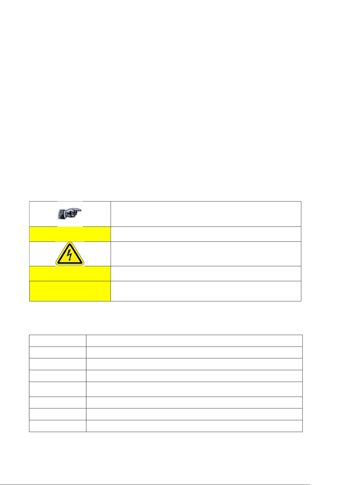
1.5 Meaning of Alert Symbols and Signal Words
Notes and Tips. Application Notes
!
! CAUTION
! WARNINIG
This part of the Manual requires your attention
In order to avoid electric shock follow the instructions provided
Indicates a potentially hazardous situation which, if not avoided, will
result in minor or moderate injury. Can cause property damage.
Indicates a potentially hazardous situation which, if not avoided, will
result in minor or moderate injury, or may result in serious injury
or death. Can cause significant property damage.
1.6 Glossary of Terms and Abbreviations
D/C Date Code (month/year)
HF High Frequency
LED Light Emitting Diode
MLC Machine Level Control
OEM Label
PJM™ Phase Jitter Modulation or PJM™ is a registered Trade Mark of Sato Vicinity
PJM StackTag® Registered Trade Mark for Sato Vicinity’s StackTag tags
P/N Part Number
MDR-4330AT (MLC6) USER MANUAL 5 83-00-001-DOC-3
Original Equipment Manufacture label is located on the back of the equipment.
It includes the Model Number, P/N, D/C, S/N and MLC
RMA Return Merchandise Authorisation
Reader Sato Vicinity’s RFID reader/writer
Reader Manger
ReaderServer
RFID
RFID inlet
RFID Label RFID inlet with adhesive backing (sticky label)
RFID Tag Generic name for RFID inlet and label
RFID reader Device for reading and writing to RFID tags
S/N Serial Number
LAN Local Area Network
Graphical user application for Windows/Linux which provides a platform for
testing, demonstrations and application development
Embedded application that provides the standard Application Programmer
Interface to serve end-user applications. This application runs on the Reader
Radio Frequency Identification
A RFID device comprising a microchip and a printed antenna
(copper/aluminium/conductive inks) on a flexible substrate (PET plastic film)
MDR-4330AT (MLC6) USER MANUAL 6 83-00-001-DOC-3
2 Product Overview
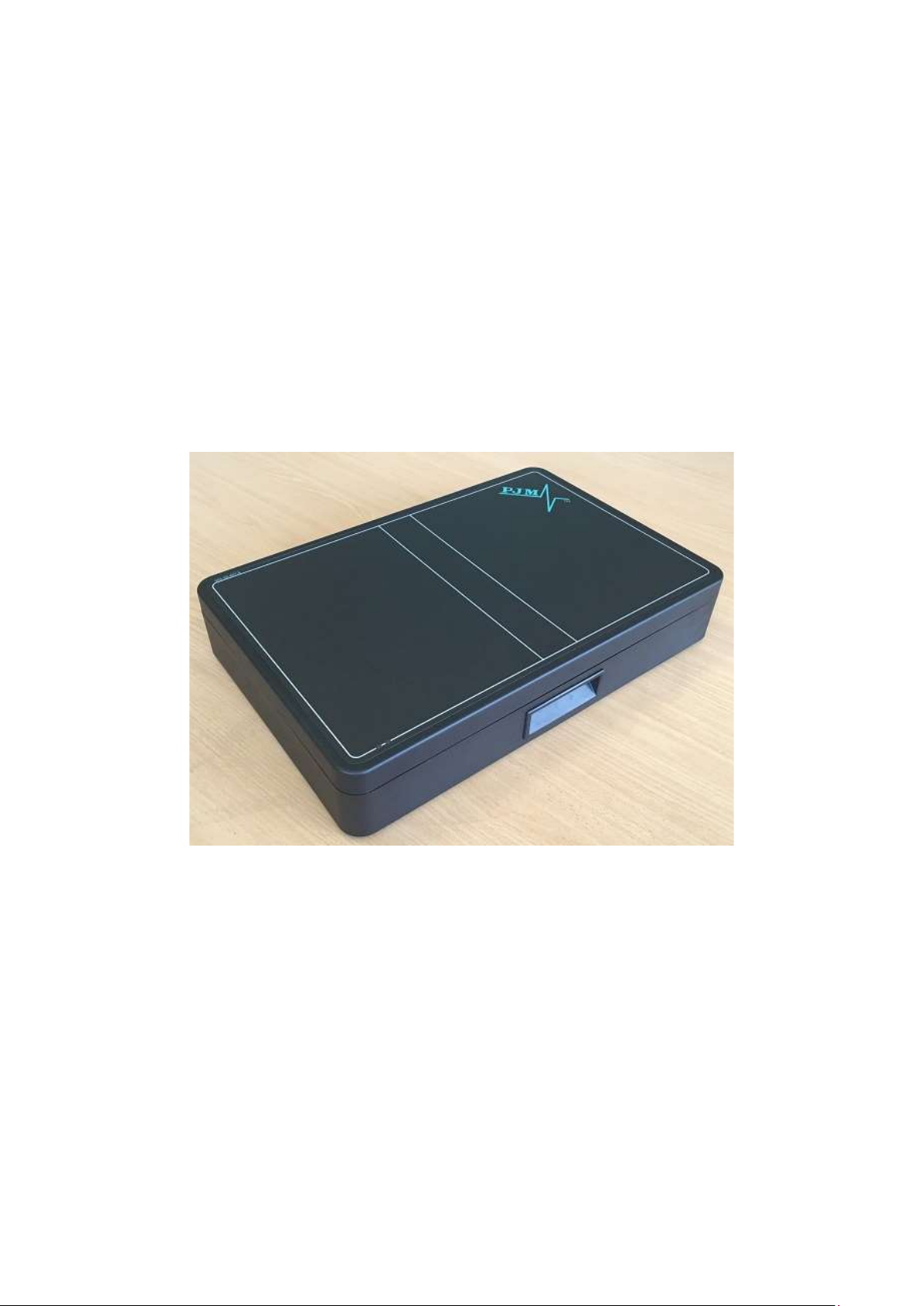
The MDR-4330AT desktop reader represents a breakthrough in 3 dimensional antenna
technology, allowing full orientation insensitive read and write capability. Large numbers of tagged
items can be quickly and accurately identified, regardless of their orientation on the reader surface.
The MDR-4330AT desktop reader is a standalone device which is fitted with full ferrite shielding
and uses field cancellation techniques to ensure there is no operational interference from surrounding
objects (such as metal shelving or other electronic equipment) and it will not interrupt operation of any
other nearby sensitive equipment.
The MDR-4330AT offers connection to a PC via Ethernet or USB and is simple to set up and use,
straight out of the box. It is supplied with our Reader Manager software which provides a platform for
reader setup, configuration, demonstration, testing and application development.
The MDR-4330AT has been successfully adopted across various industries ranging from the
medical field, Document, diamond and precious gem tracking. It is suitable for any application where
few or many tightly packed tagged items need to be read/written to quickly and accurately irrespective
of their orientation.
The communication protocol used by the M DR-4330 AT Reader is compliant with ISO/IEC
18000 - 3 Mode 2 (Air Interface at 13.56 MHz).
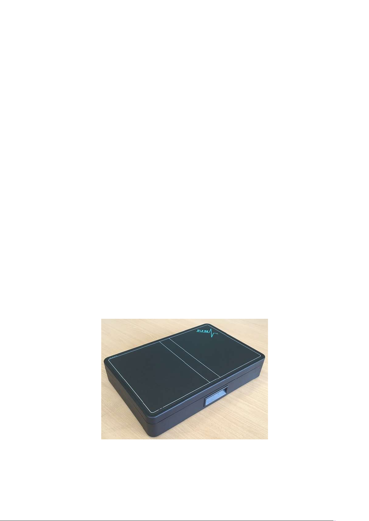
2.1 MDR-4330AT
Desktop reader-writer
Multi-axis antenna providing 3 dimensional operation
2 communication reply channels
Line reading functionality
MDR-4330AT (MLC4.1) Reader
MDR-4330AT (MLC6) USER MANUAL 7 83-00-001-DOC-3
3 Gett
ing S
tarted
3.1 Unpacking and Inspection
When you receive your reader, inspect it for any obvious damage that may have
occurred during shipment. If there is damage, notify the shipping carrier and the
supplier of the equipment or Sato Vicinity if purchased directly from Sato Vicinity
Until you have checked the reader, save the shipping carton and packaging materials in
the event the unit has to be returned.
Included with the MDR-4330AT should be the following components:
The CD-ROM will contain the following 4 files:
Reader-writer
Power adaptor - 12VDC output
Quick Start Guide & Test Results sheet
Reader Manager CD-ROM
Autorun.inf
Documentation Folder
CD-ReadMe,txt
Reader Manager-Install.exe
A power cable is not included with the supply. End-users should purchase a
power cable suitable for the country of use
Ethernet & USB cables are not included with the reader. Sato Vicinity recommends CAT5
Ethernet cable and a screened USB cable.
An RFID tag will be (required for Hardware Functionality and Communication Testing)
Will automatically launch the Reader Manager-Install.exe
Contains various PDF documents including User Manuals &
Programmer information
Text file describing all the files on the CD
The GUI application for configuration and demonstration of all
readers
Only power cables and adaptors that are compliant with the
! CAUTION
!
MDR-4330AT (MLC6) USER MANUAL 8 83-00-001-DOC-3
USB cable should be USB 2.0, screened & no longer than 3m
!
Shielded cables (USB or Ethernet) are generally required in order to comply with EMC
emissions limits, only shielded communication cables should be used.
regulations in the country of use may be connected to Sato Vicinity’s
equipment.

3.2 Before You Begin
3.2.1 Installation Environment
Sato Vicinity’s Readers are designed to operate in indoor environments where temperature and
humidity are controlled unless otherwise specified.
For standard Readers the o per a tin g temperature range is from 0oC to +45oC. The humidity
range is from 10% to 80% (non-condensing humidity).
Do not operate this reader in an environment containing
corrosive, flammable or explosives agents or conductive dust, or
! WARNINIG
Sato Vicinity’s RFID readers communicate with data carriers (RFID inlets, labels and tags) using the
13.56 MHz High Frequency (HF) band. Some industrial devices can generate unwanted noise
which may degrade communication. Make sure that other equipment is properly installed,
grounded and are at a reasonable distance.
Wireless communication can be degraded by high-voltage and high-current lines and other sources
of strong electric and magnetic fields. Installation in such locations should be avoided.
where rapid changes in temperature or vibration or shock are
likely
In order to avoid electric shock do not remove the Reader cover or attempt to
repair. Sato Vicinity’s reader-writers are to be maintained by authorised,
qualified and service-trained personnel only.
!
Removal of the Reader cover by unauthorised personnel will void the product
warranty.
3.2.2 Working with Tags
Multiple-axis Readers are tag orientation insensitive, with the exception of the
Line Read function which is necessary orientation specific.
Reading and writing speeds depend on reader-tag communication speeds and
channel numbers (communication protocol), amount of information to be read
and/or written and number of tags presented at a time. Additional numbers of
tags and information to be read/written slow down read-write communication. If
you require further information specific to your application please consult Sato
Vicinity or your support organisation.
Please note that tags and Readers can be incompatible with each other.
Bigger tags can typically work with all types of Readers. Smaller tags require
higher field strengths to communicate with a Reader and as a result they
may not communicate with some Readers or have to be closer to a
Reader antenna to function. If you require further information specific to your
application please consult Sato Vicinity or your support organisation.
MDR-4330AT (MLC6) USER MANUAL 9 83-00-001-DOC-3

3.2.3 Installation Requirements
The MDR-4330AT is a stand-alone peripheral desktop device that does not require special
installation or tuning of an internal antenna.
Power supply requirements:
Mains input: 110 - 240 VAC @ 50/60 Hz
Low voltage input (MDR-4330AT): 12 VDC @ 2.5A
3.2.4 Tag to Reader Orientation
As the MDR-4330AT is a three axis reader providing a three dimensional field so it is orientation
insensitive and the RFID tags can be presented in any orientation, vertical, horizontal, parallel or at
any angle to the reader surface, with the exception of the Line Read function which is necessary
orientation specific.
Tag Orientation Insensitive reading
3.3 Hardware Installation
MDR-4330AT User Interface Panel
MDR-4330AT (MLC6) USER MANUAL 10 83-00-001-DOC-3

Step
1
.
C
onn
ect the
supplied
12VDC
pow
er
supply
to
the reader
Step
2
. Plug
the
pow
er s
upp
l
y
into the
mains
pow
er
Power for the reader is provided by the low voltage 12VDC power supply.
MDR-4330AT with power connected
When power is applied to an MDR-4330AT Reader and the reader power switch is switched on,
the status LEDs should operate as follows:
The red LED “A” and green LED “B” will immediately illuminate then
both LEDs will be switched off after approximately 9 seconds
MDR-4330AT with red & green LED’s illuminated
The red LED will illuminate again after approximatel y 1 minute
indicating that the unit is in an operational state
Once the unit is in an operational state the red LED will remain permanently illuminated
The LED’s are controlled by the MDR-4330AT Reader software
AC
MDR-4330AT (MLC6) USER MANUAL 11 83-00-001-DOC-3

Step
3
. T
est the Rea
d
er
w
ith
a known working RFID
t
a
g. Th
e
g
ree
n LE
D
’s 1 & 2
will randomly illuminate
when an
RFID tag is su
ccessf
ully
rea
d.
3.3.1 Connecting a Reader to a Computer using USB
Connect the MDR-4330AT Reader to a host computer using a USB data communication
cable by plugging the USB cable into the MDR-4330AT “ USB Device” port and the host
computer USB port. Switch the reader on. It can take up to 4 minutes for windows to load the
USB drivers for the reader on some computers. Once the USB driver has loaded the reader
will be listed under Network adapters as a “Linux USB Ethernet/RNDIS Gadget”.
Windows operating systems may occasionally load the incorrect USB drivers for the reader. If
you experience an issue with the incorrect driver loading refer to Magellan Technology
Technical Bulletin 0009 (TB-0009), Available from Sato Vicinity or your local reseller.
MDR-4330AT with power & USB cables connected
3.3.2 Connecting a Reader to a Computer using Ethernet
Any number of Readers can be connected to a local network using an Ethernet
hub/switch. Plug the Ethernet communication cable into the MDR-4330AT RJ45 socket
(Ethernet port) and Ethernet Hub (Do not use a cross over cable). All readers on the local
area network (LAN) will be accessible by all PC’s on the same LAN.
MDR-4330AT with power & Ethernet cables connected
MDR-4330AT (MLC6) USER MANUAL 12 83-00-001-DOC-3

3.4 Reader Manager Software Installation
Step
1
. In
sert the CD s
upplied w
ith
the reader
into
the CD-ROM
.
Reader Manager is a graphical application for Windows. It provides a platform for reader
setup, configuration, demonstrations, testing and application development. When it is run,
Reader Manager can connect to a single reader at one time, it can switch between multiple
readers. Multiple copies of Reader Manager can be run, each of which can be connected to
different reader. The program provides a set of tools, each of which runs in a particular
demonstration, test or diagnostic window, all windows can be resized. This will be saved, so
the next time you run the Reader Manager, all windows will retain the size you set previously.
The position of the application on the Windows desktop is also retained.
3.4.1 Software Installation and Functionality Test
The installer should start automatically, if it does not simple open the CD directory and run the
Reader Manager-Install.exe. This contains the Python interpreter, support libraries and the
application itself. Python is the development language used by Reader Manager.
The installer looks on the system to determine which components are already present. Ticks
will appear next to the items that are not currently installed. The Python interpreter and
libraries will automatically install if required. In this case, the following window is shown: Click
“OK”
PJM Reader Manager Setup Python runtime installation popup
You will be prompted for the directory to install the Python system as shown below. In most
cases, the default directory is the best choice. Click “Install”
Python installation Destination folder selection window
MDR-4330AT (MLC6) USER MANUAL 13 83-00-001-DOC-3

You will be presented with the license agreement. Click “I Agree” to continue to the
component selection window (shown below).
By default the installer will install only a basic set of tools. The user will be limited to only
viewing tags and reader messages. This is a safe default, as it prevents users from using
tools or demonstrations and disrupting operating readers. Users who require more
functionality should enable the checkboxes as needed. Once you have made your selections
click “Next >”
Reader Manager Setup window
If the installer finds that Reader Manager has already been installed with the current
version, you can force a reinstall by manually ticking the checkbox “Next” to the
application.
You will be prompted for the directory to install Reader Manager. The default location is
the best choice but you may change the location as required, click “Next >”
Reader Manager Installation Destination folder selection window
You are prompted for the Start menu folder. The default is PJM Reader Manager, we
recommend not changing this (as shown below). Click “Install”
MDR-4330AT (MLC6) USER MANUAL 14 83-00-001-DOC-3

Step 1.
Ensure
the reader
is
switch
e
d on
with the
co
mm
uni
cat
ion
cable
Should the installation fail, click the Show Details button. Highlight the installation
detail text and press the right mouse button to select Copy Details to Clipboard. Paste
the details into an Email and Email this to your technical support contact.
Reader Manager Start Menu selection window
3.4.2 Connecting to a Reader
A Reader provides Ethernet and USB device interfaces to allow for client
connection. The USB interface uses TCP/IP networking over USB as the protocol.
This allows you to connect to a reader as if it was a normal network. So all the
usual services, such as telnet and FTP are available.
connected
When a Reader is connected to a network for the first time using either an
Ethernet cable or c o n n e c t e d t o a host computer using a USB cable, the
Reader is identified by its Model Name-Serial Number (recommended to keep the
serial number as a reference).
MDR-4330AT (MLC6) USER MANUAL 15 83-00-001-DOC-3

Step
2
.
Start
Reader Manager
t
o
vie
w
Rea
d
ers f
ound
the
LAN
Customers can add additional information to
the reader such as a physical location in the
customer ID number field. Refer to section
3.4.4 Changing the Reader’s System
Configuration of this User Manual.
Change made to the Reader’s System
Configuration will only take affect once the
reader is restarted
Tip: If you want to use the new name
immediately, simply switch the reader off
the on again to view the new name on the
Connection menu list.
When a Reader is connected to a host computer for the first time using a USB cable, the drivers
should automatically load, if they do not (Perhaps due to an older Windows OS) the Found New
Hardware Wizard will appear, perform the following steps.
1. In Found New Hardware Wizard tick “Yes”, this time only to search for software and
press “Next”.
2. In what do you want wizard to do? Tick “Install” the software automatically and press
“Next”.
3. Wait while the wizard installs the software: Linux USB Ethernet/RNDIS Gadget. Ignore
other message and press “Continue anyway”.
4. Press “Finish”.
5. Open the Connection menu to see a list of Readers and the new Reader identified by
Model Name-Serial Number on the list.
6. If you cannot find the new Reader on the list simply unplug the USB cable and plug it
again into the Reader USB device port. This time you should be able to see the
Reader’s Model Name-Serial Number.
Reader Manager will use network broadcasts to look for active readers via USB and Ethernet.
All readers found on the LAN will be listed in the Dynamic Reader List as shown in the image
below.
on
MDR-4330AT (MLC6) USER MANUAL 16 83-00-001-DOC-3

Step
3
.
C
onn
ecting to the desired Rea
d
er from the
Dynamic Reader List in Reader Manager
Locate the desired reader in the Dynamic Reader List & move your mouse pointer over any field of
the reader & double click your left mouse button. You will notice that the green status bubble to the
left of the reader turns into a green arrow & the IP address of the reader will be displayed in the
bottom right corner of the Reader Manager window.
Dynamic Reader List with reader connected
Dynamic Reader List
3.4.3 Communication Test
From the Tools menu, select System then Grid of tags sight count. See Image below
MDR-4330AT (MLC6) USER MANUAL 17 83-00-001-DOC-3
To setup static IP address connections to readers refer to the Reader Manager User
Manual (40-01-006-DOC).

Grid of tag sight counts tool selection
The Grid of tags will now be visible in the right panel of the Reader Manager window as shown
in the image below
Reader Manager with Tag Sightings window open
Place a tag on the Reader. The first square in the grid should change from white to
blue and display the tag’s ID number and the number of times the tag was sighted, should
be one (1). An example of this is shown below.
The Addition of more tags cause more squares to progressively populate with the tag’s ID
number and the number of times the tag was sighted. Removing a tag will cause the tag to
“Expire” turning the relevant square on the grid to turn dark grey (the data will be preserved).
Placing the same tag back on the reader will cause the relevant square to change from grey
back to blue & the tag count to increment to two (2), with each successive tag removal &
replacement the count will increment by one (1).
This simple test has confirmed the Reader & LAN/USB connection is working.
MDR-4330AT (MLC6) USER MANUAL 18 83-00-001-DOC-3

Tag Sightings window showing 1 tag on the reader
3.4.4 Changing the Reader System Configuration
Ensure the Reader is connected as described above. From the Tools menu, select System then
Configuration System as shown below. The Configuration System window will open.
Configuration System tool selection
MDR-4330AT (MLC6) USER MANUAL 19 83-00-001-DOC-3

The user configurable field is the Customer ID, you can enter the name you would like the
Reader to be identified as (This is useful in a large reader networks where you may need to
manage many readers). The name entered in the Customer ID field is the name that will appear
on the Reader Manager Connection menu for that reader. Power cycle the reader for the change
to be reflected in Reader Manager.
Once you have entered the desires reader name press the “Enter” key on your keyboard
then Click the “ Save” button to the right to save your changes to the reader.
System Configuration window
3.4.5 Changing the Reader’s Network Setup
Ensure the Reader is connected as described above. From the Tools menu, select System then
Configuration System as shown in section 3.3.4. The Configuration System window will open. Select
the “Network Configuration” tab as shown below. By default the reader is set to obtain an IP address
from a DHCP server. If this is not desired un-tick the “Obtain an IP address automatically” check box
and enter the required IP Address, Subnet mask & Default Gateway. Press the “Enter” key on your
keyboard then Click the “Save” button to the right to save your changes to the reader. Power
cycle the reader for the change to take effect.
MDR-4330AT (MLC6) USER MANUAL 20 83-00-001-DOC-3

Configuration System “Network Configuration” window
Ensure the IP address allocated to the reader is recorded for future reference.
Applying a label to the reader showing the allocated IP address is ideal.
!
Tip: If you make an error in the reader Network configuration the reader may no
longer be visible on the network (wrong IP range for example). If this happens you
can connect to the reader using a USB cable & correct the issue
4. Line Reading
4.1 Line Reading Functionality
All MDR-4330AT readers from MLC 4.1 onward have native Line Reading capability which allows
users to quickly locate a specific item within a large tag population.
How the Line Reading functionality works
The Line Read functionality is native to the reader and is controlled via the client application software,
the Line Read works in two distinct stages as follows:-
Stage 1) Initial item location within a large tag population
When searching for a single specific item you may or you may not know the container in
which the item is located, in either situation you will enter the details of the item you are
searching for into your application, this will set the reader to seek mode. If you do know the
container in which the item is located you can simply place the container on the reader & the
reader it will confirm it has identified the RFID tag associated with the item you are searching
for, the reader can now be set to Line Read mode via the application. If you do not know the
container in which the item is located you can simply place your containers on the reader
surface, one by one until the reader confirms it has identified the RFID tag that is associated
MDR-4330AT (MLC6) USER MANUAL 21 83-00-001-DOC-3

with the item you are searching for. The reader can now be set to Line Read mode via your
application.
Stage 2) Item location within the container
Once you have identified the specific container in which an item is located, the Line Read
function will very quickly help you narrow down the location of the item within the container.
This is achieved by simply moving the container across the clearly marked Line Read area on
the Reader (See “Line Read Area” image below)
Line Read Area
The Item you are searching will only be identified when it is presented to the narrow Line
Read area, you can then very quickly drill down on the small number of items with the Line
Read Area to locate the required item. Once the item has been confirmed as located the user
will acknowledge this in the application and the reader will be set back to normal operation.
In the example below (see Tray of gems undergoing Line Read image) we can see a tray of
gemstones being moved from right to left, as soon as the required item is identified within the Line
Read area the user is notified enabling quick item location. In the example below the item is located in
the right most row of items.
Tray of gems undergoing Line Read
MDR-4330AT (MLC6) USER MANUAL 22 83-00-001-DOC-3

5. Troubleshooting
Issue
Cause
Solution
No Power – All
LED’s are off
Absence of the
flashing green
LED’s during tag
reading
Cannot find and
connect to the reader
as the reader is not
shown on the
Dynamic Reader List
Power cable not connected
Power Cable faulty Replace the cable
Power Adaptor faulty Replace the power adaptor.
Reader Faulty Contact your local supplier for support
Fuse blown Replace fuse with an equivalent 5 x 20mm
Faulty tag/tags Replace tag/tags. Do not use tags with a
The Powering Field is off
USB or Ethernet connection
is not functioning
The tag type is incompatible
with the reader
Reader faulty Contact your local supplier for support
The reader is not connected Ensure the Ethernet/USB cable is
Invalid Network configuration The computer IP address on the computer
USB drivers still loading USB connected readers may take some
Data Cable Test USB/Ethernet cable
Reader faulty Contact your local supplier for support
Ensure the power cable is connected
correctly to both the mains power and to
the Reader
3A 250VAC rated fuse
black dot or black square marking (faulty
tags).
Ensure the powering field is on. Go
to Tools> System>Reader Setting. Tick
the Powering Field box.
Ensure the Ethernet/USB cable is working
correctly, try using an alternative cable.
Power cycle the Reader & restart the host
computer.
Use the appropriate tag type for the reader,
contact your local supplier to help with tag
compatibility information
connected properly to both the reader &
host computer
running Reader Manager must be in the
same subnet as the reader
time to negotiate an address. Check the
Network Connections window in the
Control Panel to confirm that a connection
has been established
MDR-4330AT (MLC6) USER MANUAL 23 83-00-001-DOC-3

6. Document Revision History
Version
Date
Person
Change
Ver 1.0 17 Nov 2014 Steve Antonio Initial Release of 83-00-001-DOC
Ver 2.0 23 Nov 2017 Steve Antonio Update to MLC4.1 with line read 83-00-001-DOC-2
MDR-4330AT (MLC6) USER MANUAL 24 83-00-001-DOC-3

7. A
ppendi
x
7.1 MDR-4330AT Product Specification
Electrical
Operating Frequency 13.56 MHz
ISO/IEC Compliance ISO/IEC 18000-3 Mode 2
Command Data Rate 424 kbit/s
Reply Data Rate 106 kbit/s per channel
Number of Reply Channels 2
Number of Axes 3
Operating Range Marked read/write area
Power Supply 12 VDC
DC Power Supply Connector 2.5 mm DC centre pin positive
Power Consumption 42W
Performance
Identification rate Up to 150 tags/s
Host
Host Interface USB, Ethernet
Minimum Host Requirements Windows 7 or later
Environmental
Operating Environment Indoor use
Temperature Range 0°C to +45°C ambient
Humidity 10% to 80% (non-condensing)
Reader Placement Can be placed next to each other
Mechanical
External Dimensions: (L x W x H) 440 x 290 x 84 mm
Net Weight 7.85 kg
Net Volume 0.00074 m3
Certifications
USA TBA
Other Features
Operation
Calibration and Tuning No manual calibration or tuning required
Powerful processing platform allowing for standalone reader operation
Shielding Methods Ferrite and Field Cancellation
Line Reading Functionality RFID field unaffected by liquids
MDR-4330AT (MLC6) USER MANUAL 25 83-00-001-DOC-3
 Loading...