


Magellan
Reader Manager
Guide
Document Number : 40-01-006-DOC
Last Changed : 14 September 2006
Version: 2.01
Copyright Magellan Technology 2005
Commercial in Confidence

Document
Number
Reference Documents
Description Date Version
40-01-000-DOC Applications Programmer’s Guide
For Version 3 Reader Server
45-00-001-SPC BT and ST Chip Logical Specification 30 June 2003 Ver 2
27 June 2006
Document History
Date Version
14 Dec 2005 1 Jeff Gray original document Jeff Gray
6 Sep. 06 2.00 Changed formatting, updated to show new tools. Daryl Dusheiko
14 Sep. 06 2.01 Added more instructions to the axis test section. Daryl Dusheiko
Change Description Author

Table of Contents
1 INTRODUCTION...................................................................................................................................................1
2 FREQUENTLY ASKED QUESTIONS ................................................................................................................2
2.1
H
OW DO I INSTALL OR UPGRADE READERMANAGER
2.2
H
OW TO CONNECT READERMANAGER TO A READER
2.3
I
HAVE A NEW READER, WHAT DO I DO NOW
2.4
H
OW DO I CHANGE THE NETWORK SETTINGS ON A READER
2.5
H
OW DO I SET A TAG TO NORMAL POWERED MODE
2.6
H
OW DO I RESTORE THE READER TO ITS DEFAULT SETTINGS
2.7
H
OW DO I GET THE READERSERVER VERSION OF MY NETWORK BASED READER
3 INSTALLATION....................................................................................................................................................4
3.1
N
EW INSTALLATION
3.2
U
PGRADING READERMANAGER SOFTWARE
3.3
S
TARTING READERMANAGER
3.4
G
ETTING SOFTWARE UPGRADES
4 THE READERMANAGER DESKTOP................................................................................................................7
4.1
R
EADERMANAGER MENU BAR
4.2
R
EADER MANAGER STATUS BAR
5 MANAGING CONNECTIONS...........................................................................................................................12
5.1
D
EFINING A STATIC CONNECTION
5.2
C
LOSING A CONNECTION
6 TOOLS................................................................................................................................................................... 15
.........................................................................................................................................4
..........................................................................................................................5
.......................................................................................................................5
........................................................................................................................7
...................................................................................................................10
...................................................................................................................12
................................................................................................................................14
? ...................................................................................................2
...................................................................................................... 4
? ......................................................................................2
?...................................................................................... 2
?.............................................................................2
?........................................................................................ 2
?...........................................................................3
?............................................3
6.1
C
ONFIGURATION SYSTEM
6.2
C
ONSOLE
6.3
G
RID OF TAG SIGHT COUNTS
6.4
I
MMEDIATE COMMAND
6.5
I
NTERROGATE COMMAND
6.6
M
EMORY MAP
6.7
R
EADER SETTINGS
6.8
R
EADER SETUP
6.9
S
IMPLE TAG TEST
6.10 T
6.11 T
7 READER CONFIGURATIONS..........................................................................................................................49
7.1
7.2
8 UPGRADING READER SOFTWARE...............................................................................................................51
8.1
9 TROUBLESHOOTING........................................................................................................................................53
9.1
9.2
9.3
10 REPORTING A PROBLEM................................................................................................................................54
11 MINIMUM SYSTEM REQUIREMENTS..........................................................................................................55
ABLE OF TAG MESSAGES
AG TEST
E
DIT CONFIGURATIONS DIALOG
R
EADER CONFIGURATION DIALOG
U
PGRADING
CAN’
M
Y READER IS BEHAVING STRANGELY OR TAGS ARE TIMING OUT
M
Y ANTENNA IS NOT IN THE READER SETUP TOOL ANTENNA LIST
........................................................................................................................................................18
................................................................................................................................................24
...............................................................................................................................................32
...........................................................................................................................................45
.......................................................................................................................................................47
ARM
T SEE MY READER ON THE DYNAMIC CONNECTION LIST
...............................................................................................................................16
..........................................................................................................................20
.................................................................................................................................. 21
..............................................................................................................................23
..........................................................................................................................................26
..............................................................................................................................46
.....................................................................................................................49
..................................................................................................................49
AND X86 READERS
............................................................................................................51
.......................................................................... 53
...................................................................53
.................................................................. 53
12 GETTING MORE INFORMATION ..................................................................................................................56
13 APPENDIX A – AVR OPTIONS.........................................................................................................................57
13.1 U
13.2 O
13.3 T
PGRADING AN
PENING A CONNECTION USING THE COMMAND LINE
ROUBLE SHOOTING
AVR S
AVR
ERIES READER
PROBLEMS
...........................................................................................................57
............................................................................................................58
..................................................................................57

1 Introduction
The ReaderManager is a graphical application for Windows and Unix. It provides a platform for reader
setup, configuration, demonstrations, testing and application development.
When it is run, the ReaderManager can connect to a single reader at one time. It can switch between
multiple readers.
Multiple copies of ReaderManager can be run, each of which can be connected to different readers.
The program provides a set of tools, each of which is a particular demonstration, test or diagnostic
window.
All windows can be resized. This will be saved, so the next time you run the ReaderManager, all
windows will retain the size you set the last time. The position of the application on the Windows
desktop is also retained.
Reader Manager Guide Page 1 of 62 40-10-006-DOC 15/09/2006

2 Frequently asked Questions
This section provides a list of commonly asked questions.
2.1 How do I install or upgrade ReaderManager?
1. Run the install program ReaderManager-Install.exe. This can be downloaded from the Magellan
website www.magtech.com.au, or run from the CD supplied with your reader.
2. If you already have ReaderManager installed run the program ReaderManager-Upgrade.exe.
3. Follow the installation instructions given in section 3 Installation.
2.2 How to connect ReaderManager to a reader?
1. Connect an Ethernet cable or USB cable to the reader as described in reader manual. Apply power to
the reader.
2. Wait about 40 seconds for the reader to start up.
3. Either select the reader from the Dynamic Reader list on the Connection menu as described in 5.1.2
Opening a Dynamic Connections, or create a static connection as described in section 5 Managing
Connections.
2.3 I have a new reader, what do I do now?
1. You will need the following equipment to setup a reader.
• DC Voltmeter
• Antenna tuning block and trim tool.
• Normal powered tag.
2. Open the Reader Setup tool as described in section 6.8 Reader Setup.
3. Follow instructions provided by the wizard selecting and configuring the number of axis Groups,
selecting, tuning and testing the antennas used with the reader. Save the configuration to the reader.
2.4 How do I change the network settings on a reader?
1. Open the Configuration System tool as descried in section 6.1 Configuration System.
2. Changing the Customer ID field will change the name of the reader as displayed on the dynamic
connections menu.
3. Click the Network Settings tab to set a fixed IP address or to obtain an IP address from a DHCP
server.
2.5 How do I set a tag to Normal Powered mode?
1. Open the Console. Right click in the Message log area and ensure that Show Tag Replies is ticked.
2. Place a tag on the reader, you should see a response from the tag.
3. From the Reader Configuration menu select Config_Normal_Powered_Tag.
4. You should get a response from the reader with the data value equal to 6000. A typical response
looks as follows:
Info,Reply:Timestamp 7fff, LockPointer 0004, Manufacturing e005, SpecificID 000f8ff5, GroupID 2000, ConditionalID ffff,
Configuration 6000, ReadAddress 0006,
5. Remove the tag from the antenna.
Reader Manager Guide Page 2 of 62 40-10-006-DOC 15/09/2006
Data: 6000

6. From the Reader Configuration menu select ClearAll.
2.6 How do I restore the reader to its default settings?
1. Open the Reader Settings tool.
2. Click the Clear Saved Settings button.
3. Power the reader off then on.
2.7 How do I get the ReaderServer version of my Network based reader?
•
Open the Console tool.
•
Type Version() in the Command Entry area.
•
The ReaderServer and operating system will be shown in the Message Log area.
Reader Manager Guide Page 3 of 62 40-10-006-DOC 15/09/2006
3 Installation
This section describes how to install, upgrade and start ReaderManager and how to get ReaderManager
updates.
Installation instructions are only given for installation on a computer running Microsoft Windows, for
installation on computers running Linux please contact Magellan Technology.
3.1 New Installation
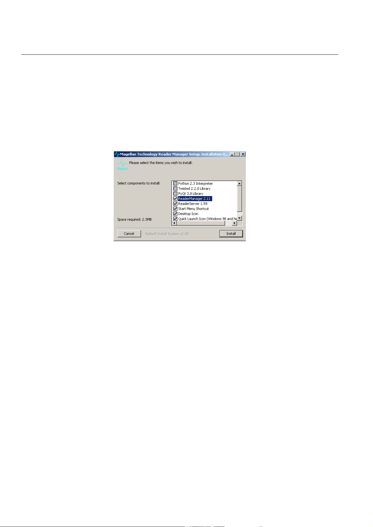
All that needs to be done is to run ReaderManager-Install.exe. This contains the Python interpreter, the
PyQt and Twisted libraries and the application itself. When it is run, the window shown as Figure 1
appears.
Figure 1
The installer looks on the system to determine which components are already present. Ticks will appear
next to the items that are not currently installed. The Python, PyQt and Twisted libraries will
automatically install if required.
The version numbers of the components are shown next to their names.
If the installer finds that ReaderManager has already been installed with the current version, the user can
force a reinstall by manually ticking the checkbox next to the application.
The only directory selection that you are ever offered is when you install Python (which is part of
ReaderManager-Install.exe). It offers a default directory of C:\Python23. This can be changed to
C:\Program Files\Python23, for example, but you can put it anywhere you like.
When the ReaderManager application is installed, it is placed inside the Python directory. This is
determined automatically by the installer.
3.2 Upgrading ReaderManager software
Most of the time, software upgrades will not involve a change in the version of Python, PyQt and
Twisted libraries. In this case, all that needs to be done is to get the new version of ReaderManager-
Upgrade.exe and run this file. This file is much smaller than the full installation. The upgrade window is
shown in Figure 2.
Reader Manager Guide Page 4 of 62 40-10-006-DOC 15/09/2006
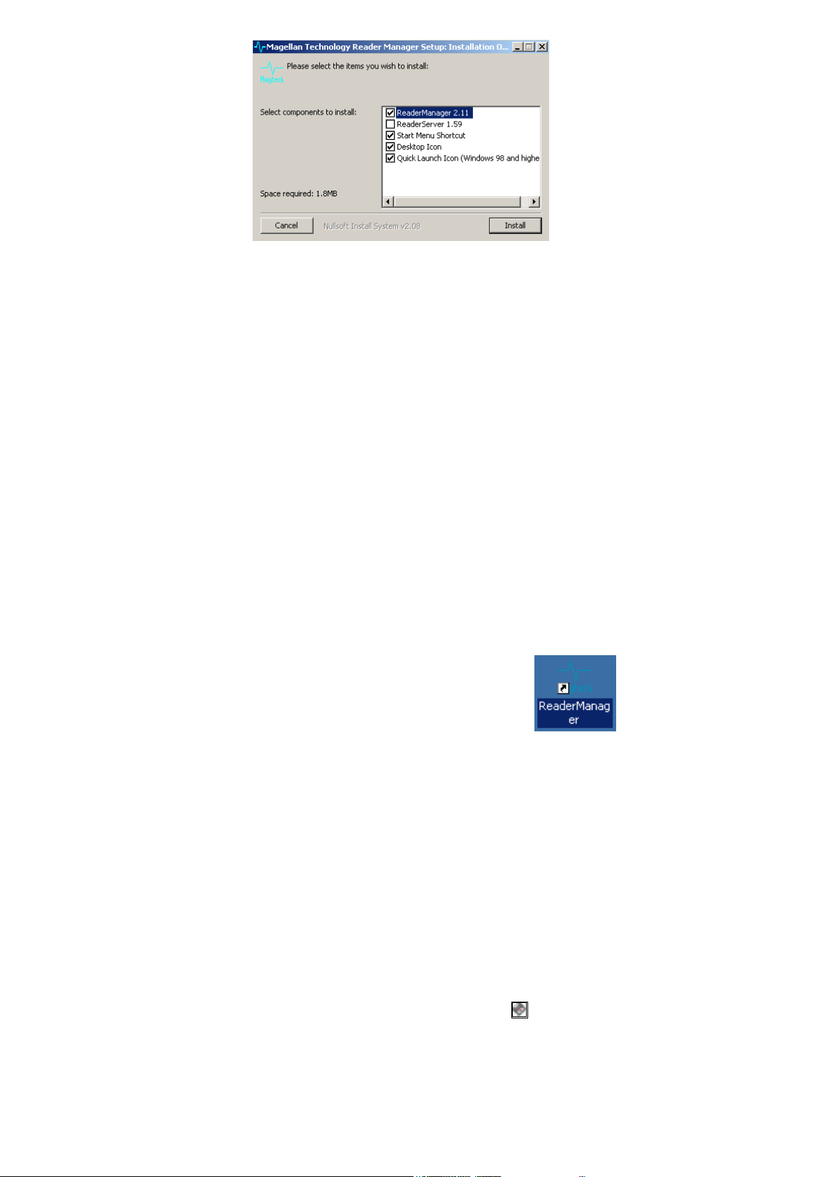
Figure 2
Like the -Install version, this installer will check the currently installed application versions and un-tick
already installed components accordingly. The user can manually tick an application to force
reinstallation.
If the version of the Python, PyQt libraries or Twisted libraries is not present, is damaged or has
changed, the installer will indicate that a full install is required. In this case it will be necessary to
follow these steps:
1. Run the Control Panel and select the Add Or Remove Programs item.
2. Uninstall Magellan ReaderManager if it is present.
3. Uninstall Python, PyQt and Twisted if it is present.
4. Close the Control Panel.
5. Using a file manager, such as My Computer, delete the Python directory if it remains.
6. Follow section 3.1 New Installation to install the full version.
3.3 Starting ReaderManager
The installer will put an icon on the Windows desktop and add an application folder to the programs
start bar.
•
To start ReaderManager from the desktop icon, double click the icon .
•
To start Reader Manage from the Windows start menu; click Start then All Programs, then Magellan
Technology, then click Reader Manager.
3.4 Getting Software Upgrades
Magellan Technology releases periodic software updates via their Web site.
Users can use our Web site to get software update files. You will need to be running a browser such as
Mozilla or Internet Explorer, then follow these steps:
1. The updates are stored on our Web site at the address http://www.magtech.com.au/downloads/
A username and password is required to access the downloads page. Please contact Magellan or the
supplier of the equipment to arrange for an account to be setup. Once connected, click the link, Click
here to continue to the page from which you came. You will see a list of files. Follow these steps for
each file to download it.
2. Point the mouse at the file you want. This is shown as a disk icon .
Press the right mouse button, so the context menu pops up.
3.
4. Select the Save Target As... menu item.
5. A file save dialog box will then appear. Change directories to where you want to save the file. It does
Reader Manager Guide Page 5 of 62 40-10-006-DOC 15/09/2006

not matter where you save it. Just note which directory it is in. Click the Save button to complete this
action.
Installation files can be run from any directory, even directly off a CD-ROM.
Reader Manager Guide Page 6 of 62 40-10-006-DOC 15/09/2006

4 The ReaderManager Desktop
This section gives a brief overview of the main ReaderManager elements, such as the menu bar, desktop
and status bar.
The ReaderManager desktop is shown in Figure 3 and consists of several items:
1. The menu bar, providing the primary user interface to ReaderManager.
2. The main window, which can contain one or more tool windows open at any given time.
3. A status line at the bottom used to show connection information between ReaderManager and the
reader.
1
2
3
4.1 ReaderManager Menu Bar
Figure 3
The ReaderManager menu bar consists of the following main menus items; File, Connection, Tools,
Reader Configuration, Window and Help. These menu items are explained in more detail below.
4.1.1 File Menu
To show the file menu click File on the main ReaderManager menu.
The File menu items are described in Table 1.
Reader Manager Guide Page 7 of 62 40-10-006-DOC 15/09/2006
Sub Menu Description
Preferences
Print
Print Preview
Upgrade
Quit Exit the application.
Opens a dialog box which allows the user to change the font, user level, language and
upgrade directory.
For tools which support this function, allows the user to print a text representation of the
active tool.
For tools which support this function, allows the user to preview a text representation of the
active tool which can be printed.
There are two options available:
Upgrade AVR readers – opens a dialog window which allows the user to upgrade the
firmware or FPGA on an AVR type reader.
Upgrade DSB or x86 readers – opens a dialog window which allows the user to upgrade
network based readers.
Table 1
4.1.2 Connection Menu
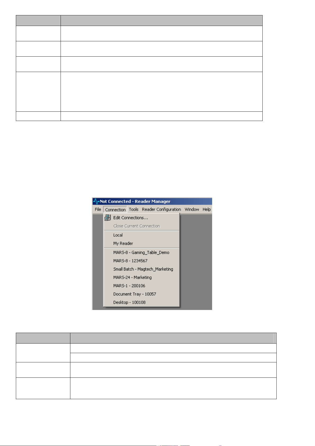
To show the connection menu click Connection from the main ReaderManager menu.
The connection menu shows all readers which can be connected to using ReaderManager. The menu
also provides options to edit static connections and close the connection to the reader.
The Connection menu options are shown in Figure 4, the menu items are described in Table 2.
1
2
3
Figure 4
Index Description
1
2
3
Reader Manager Guide Page 8 of 62 40-10-006-DOC 15/09/2006
Edit Connections - Allows the user to create and edit static connections to reader.
Close current connection - Disconnect ReaderManager from the currently connected reader.
Static connections area - This section shows static connections created using the Edit
Connections menu option. Static menu options are saved when ReaderManager is closed.
Dynamic connection area - ReaderManager automatically detects readers connected on a
network. These readers are shown in the dynamic connection area. This menu may look
different on your installation.
Table 2
4.1.3 Tools Menu
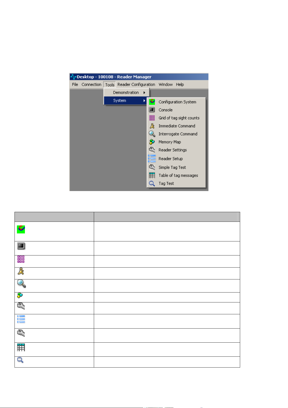
From the main ReaderManager menu click Tools.
If ReaderManager is not connected to a reader only the Console tool is shown in this menu. When
ReaderManager is connected to a reader there will be two sub menu items, Demonstrations and System.
This document will only describe the System menu options. A detailed description of all System tools is
given in section 6 Tools. The System tools menu is shown in Figure 5.
Sub Menu Description
Configuration System
Console
Grid of tag sight counts
Immediate Command
Interrogate Command
Memory Map
Reader Settings
Reader Setup
Figure 5
Allows the user to view reader module part numbers, versions and serial
numbers. Also provides an interface to change the readers networks
setup.
Use this tool to send commands to the reader and view all reader
messages.
Use this tool to graphically view all tags sighted by the reader.
Use this tool to construct an Immediate command.
Use this tool to construct an Interrogate command.
Use this tool to show and change tag memory.
Use this tool to view and change various reader operating parameters.
Use this tool to configure the reader to work with various antennas and
to tune and test each antenna.
Simple Tag Test
Table of Tag messages
Tag Test
Reader Manager Guide Page 9 of 62 40-10-006-DOC 15/09/2006
Provides a tool used to read and write to various memory locations and
verifies the data is written correctly.
This tool displays a table of tag related messages received from the
reader sorted by a timestamp.
More advanced tags test. Used mainly by tag and chip manufactures.
Table 3
4.1.4 Reader Configuration
From the main ReaderManager menu click Reader Configuration. This menu item provides access to all
user defined scripts and commands. The menu also provides an item to open a form which is used to
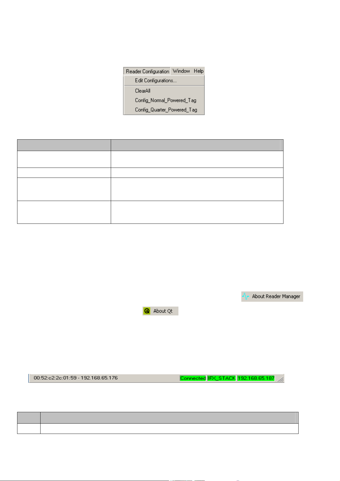
create and edit scripts. The default menu is shown in Figure 6:
Figure 6
Sub Menu Description
Edit Configurations Provides an interface to create and edit custom scripts and tag
commands.
Clear All Clears Interrogate and Immediate commands.
Config_Normal_Powered_Tag This script sets an Action command to write 2000 to the configuration
word. Use this script to set all the tags placed on a reader to Normal
Powered Mode.
Config_Quarter_Powered_Tag This script sets an Action command to write 4000 to the configuration
word. Use this script to set all the tags placed on a reader to Quarter
Powered Mode.
Table 4
4.1.5 Window
This menu option allows the user to arrange various tools on the desktop.
4.1.6 Help
This menu allows the user to get the version number of Reader Manager and Qt.
To get the Reader Manager version click Help then click About ReaderManager .
To get the Qt library version click About Qt .
4.2 Reader Manager Status Bar
The status bar indicates various reader connection states and displays the active tag type. It is divided
into four areas, these are shown in Figure 7 and described in Table 5.
1 2 3 4
Figure 7
Index
1 This area shows the following information:
Reader Manager Guide Page 10 of 62 40-10-006-DOC 15/09/2006
Description

Index
The MAC address and IP address when the mouse is moved over a reader name in the dynamic connection
menu.
Shows connection status – Connecting -> Getting Settings -> Connected -> Disconnected.
2 Indicates reader manager is connected / disconnected to / from the Reader Server.
On AVR reader indicates if the reader server is connected to the reader. On all other readers shows the tag
3
type.
4 On AVR readers shows the tag type. On all other readers shows the IP address of the connected reader
Description
Table 5
Reader Manager Guide Page 11 of 62 40-10-006-DOC 15/09/2006
5 Managing Connections
11 12
This section details how to create static connection profiles, how to connect or disconnect
ReaderManager from a reader.
The ReaderManager is capable of connecting to a variety of readers. Each reader is distinguished by a
number of parameters which give it a unique address. The set of all these parameters is referred to as a
connection profile.
This includes connections to all kinds of readers across the network or AVR Series readers that are
running on the same PC as the ReaderManager.
There are two ways to connect to a reader:
1. Defining a static connection or,
2. Using the dynamic reader discovery feature in ReaderManager.
5.1 Defining a Static Connection
To access the Edit Connections dialog, select Connections->Edit Connections.
When you first start ReaderManager, you only have the Local connection configured, which is a default
AVR Series reader connection. You may want to connect to a ReaderServer somewhere else on the
network, or another local reader.
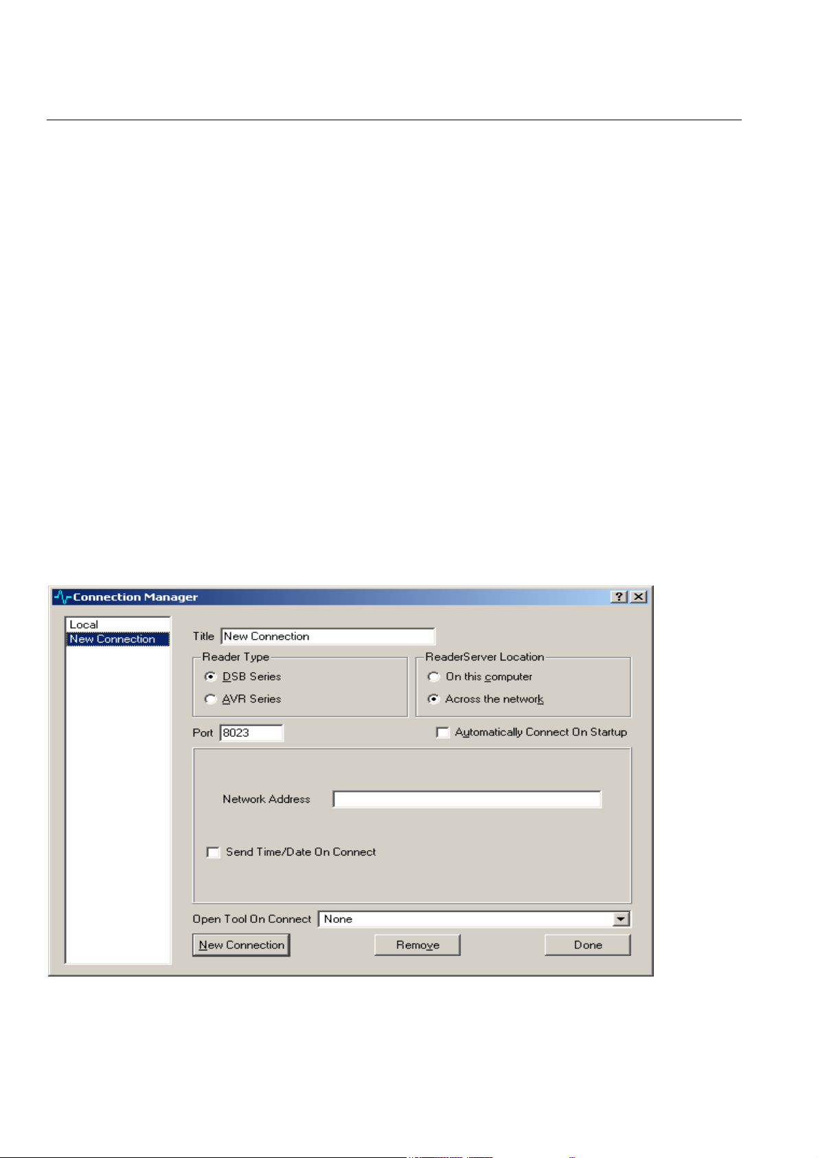
The connection dialog is shown in Figure 8, its elements are described in Table 6.
2
1
8
3 4
5 6
7
9
10
Figure 8
Reader Manager Guide Page 12 of 62 40-10-006-DOC 15/09/2006
Index
Shows the names of already defined static connections. To edit an already defined
1
connection, click on the name and change the required fields on the right hand side of the
dialog.
Title is the text that will appear in the Connection menu and in the list of connections in this
2
dialog. This can be any name that can act as a brief summary of the reader being connected
to. For example, the reader type, network address shortcut or location can be used.
3 For network based readers select DSB Series. For AVR type readers select AVR series.
For network based readers select Across the network. For AVR type readers select On this
4
computer. The selection for this item will adjust the options that appear in the middle portion
of this window.
5 This field defines the TCP port used to connect to the reader server. It should be left as 8023.
Automatically Connect On Startup can only be ticked for a single connection in the list. It
6
defines which connection will be opened automatically when the ReaderManager is run. This
can be convenient if only a single reader is ever used with this application.
When across a network is selected, Network Address is the address of the ReaderServer,
7
either as a domain name or an IP address. e.g. 192.168.0.25.
Send Time/Date On Connect if ticked will generate a command to set a remote reader to the
8
current time and date of the computer that ReaderManager is being run on. This is useful for
readers that do not retain time and date information when powered off.
Open Tool On Connect will automatically open the specified item from the Tool menu that is
9
selected when this program connects to this reader. Different connections may open different
tools. This is convenient if a particular tool is commonly used with a given reader.
Description
10 Click this button to create a new connection profile
11 Click this button to remove a connection profile.
12
Click this button to complete the connection editing or creation process. Connection as saved
when you exit the ReaderManager application.
On AVR readers the following items are displayed in the middle portion of the form:
When on this computer is selected, Location of ReaderServer shows where the ReaderServer
application can be found. It should automatically load the correct directory in most cases. If
not, click on the Find ReaderServer... button and go to the
<PythonPath>\Lib\ReaderServer\DTRHF\ directory. You do not need to select a file, just
this directory.
The Serial Port drop down list allows the name of the serial port that the reader is connected
to be selected. It is also possible to edit this line to enter a custom name.
Table 6
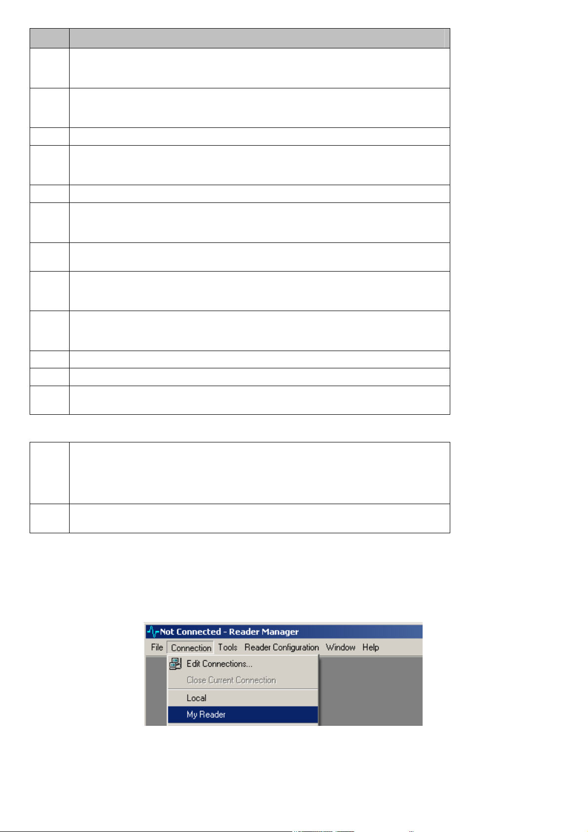
5.1.1 Opening a Static Connection
Select Connection from the main ReaderManager menu. The connection menu is shown in Figure 9.
Figure 9
Reader Manager Guide Page 13 of 62 40-10-006-DOC 15/09/2006
Select the connection profile you would like to connect to. Statically defined connection profiles are
shown below the Close Current Connection item.
The message on the right of the status bar will change to Connected in green if the ReaderManager
successfully connected to the reader.
For connections to a ReaderServer on the same computer, a status message will indicate that the server
is being started automatically. This takes a little longer than a network connection because of this
activity.
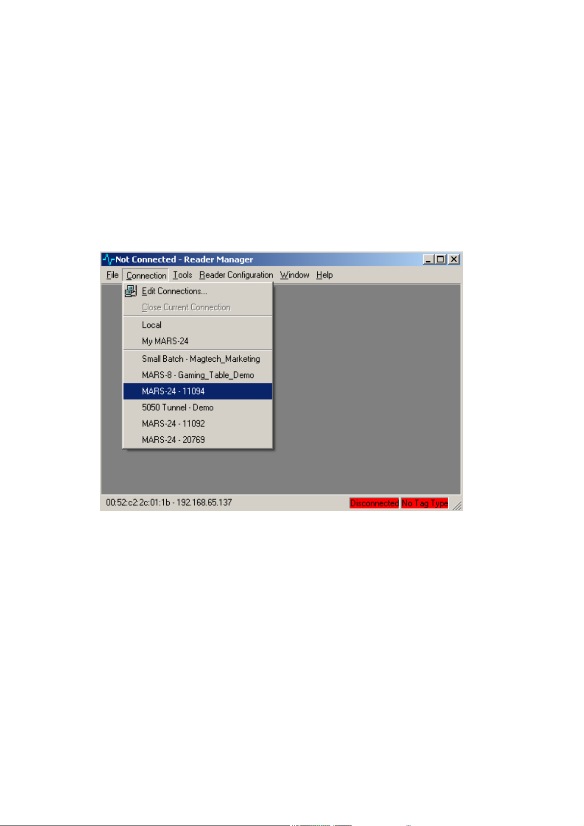
5.1.2 Opening a Dynamic Connections
ReaderManager uses multicast addressing to discover readers on a network. Figure 10 shows a typical
connection menu showing various readers detected on a network. It is not necessary to define a profile
for readers to be discovered on a network.
Figure 10
Readers are labelled as either:
<Reader Type> - <Serial Number> or as,
<Reader Type> - <User defined name> or as,
<Mac Address> - <IP address>.
When the menu item is highlighted the MAC and IP address is shown on the status bar.
5.2 Closing a Connection
When connected to a reader, the menu item Close Current Connection can be selected in the Connection
menu. If a local ReaderServer has been automatically started when the connection was established, it
will be automatically shutdown as well.
Reader Manager Guide Page 14 of 62 40-10-006-DOC 15/09/2006

6 Tools
This section gives a more detailed explanation of the System tools available in the Tools menu.
It is possible to open more than one tool at the same time. They are shown overlapped in the main
window area.
The Window menu contains options which allow the open windows to be cascaded or tiled. Also, any
open tool can be selected, so it can be seen in the foreground.
Some tools will issue commands to the reader to change its operating state. Because of this, some
tools cannot be used at the same time because they operate by expecting a particular mode of
operation.
In this case, closing the window or ReaderManager will not solve the problem, because the reader is
still operating in whatever mode it was told to. If you think the reader has become confused in a
case like this, the best way to resolve it is to shut down the ReaderManager and the reader, then start
from scratch.
Fortunately, most windows are passive and do not cause problems like this.
Reader Manager Guide Page 15 of 62 40-10-006-DOC 15/09/2006
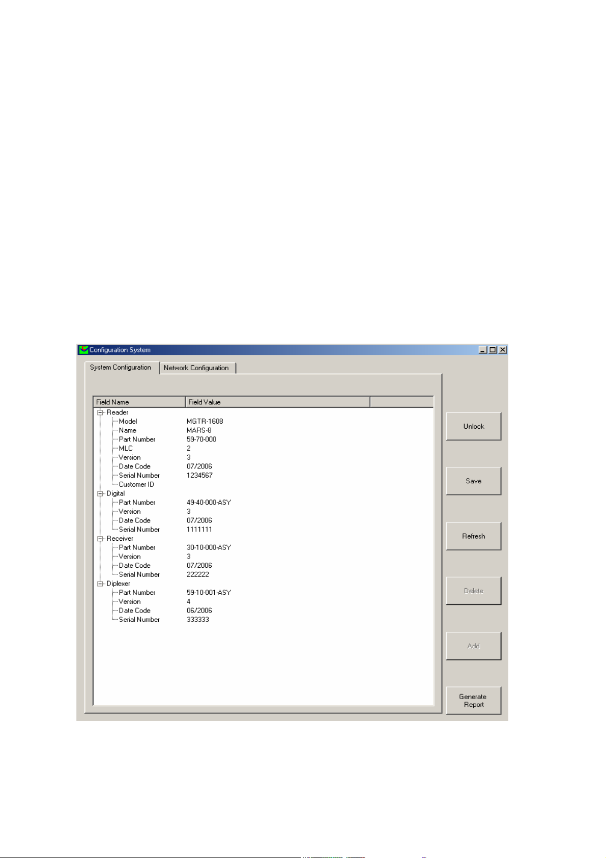
6.1 Configuration System
This tool is used to view the reader’s hardware module part numbers and version numbers. The tool is
also used to set the networks settings and to change the name of the reader as seen on the network.
To access this tool, select Tools->System->Configuration System.
The configuration system tool consists of two tab items:
1. System configuration – shows part and version numbers of various components which make up a
reader.
2. Network configuration – shows the current reader network settings.
6.1.1 System Configuration Tab
The configuration system tool is shown in Figure 11. Your section names, part and version numbers may
be different to what is shown in this document, depending on what type of reader, ReaderManager is
connected to.
Most fields in the configuration system require a password to change the field value. The CustomerID
field does not require a password and is provided for the user to assign a descriptive name to the reader.
This name will appear in the multicast messages from the reader and will be shown in the dynamic
connection area on the Connection menu. Table 7 describes the various elements of the tool.
1
2
4
5
3
6
7
8
9
Figure 11
Reader Manager Guide Page 16 of 62 40-10-006-DOC 15/09/2006

Index
Click this tab to show the part numbers and version numbers of various components which
1
make up a reader.
2 Click this tab to show the reader’s network settings.
This field allows the user to give the reader a descriptive name. This name will appear on the
dynamic connection list and will be the hostname of the reader on the network.
Description
3
4
5 Click this button to save any changes to the reader.
6 Click this button to refresh the list from the last saved values.
7 Click this button to delete a custom field. Only custom fields can be deleted.
8 Click this button to add a custom field name and value to any reader section.
9 Click this button to create a packing report prior to shipping a reader.
1. Click the field column opposite Customer ID.
2. Enter the name you would like assigned to the reader.
3. Press Enter.
Click this button to unlock the password protected fields. The user will be prompted to enter
a password.
Table 7
6.1.2 Network Configuration Tab
The Network Configuration tab provides fields for the user to setup the reader to get an IP address from
a DHCP server to use a static IP address. The network configuration tab is shown in Figure 12.
1
Figure 12
Index
1 Tick this to set the reader to get an IP address from a DHCP server.
2 If (1) is not ticked enter the IP address used by the reader.
3 Enter the subnet mask based on the IP address entered in (2)
4 Enter the default gateway IP address. (Optional)
Description
Table 8
2
3
4
Reader Manager Guide Page 17 of 62 40-10-006-DOC 15/09/2006

6.2 Console
1
2
3
The console dialog provides a command line interface to a reader. Reader commands are described in
the Application Programmers Guide (40-01-000-DOC). The Command Entry area also accepts Python
code. The console tool is shown in Figure 14. Table 8 describes the various elements of the Console
tool.
To access this tool select, Tools->System->Console.
Figure 13
Index
1 Message Log window shows all message received from the reader.
2 Window size adjustment bar. Use this to change the size of the Message Log and Command Entry windows.
3 Command Entry window provides an area to enter command to send to the reader.
Description
Figure 14
Clicking the right mouse button in the Message Log brings up a menu. This is the means of controlling
the behaviour of the console.
•
If text has been selected in the Message Log window, it can be copied into the clipboard for pasting
elsewhere.
•
Clear will remove all the text in this window.
•
Show Tag Replies enables the display of tag messages and tag expired message. By default, this is
turned off, because in applications where large numbers of tags are being processed, it will bring the
application to a halt updating this window with tag messages. Each time this option is selected, it will
turn this option on or off.
Reader Manager Guide Page 18 of 62 40-10-006-DOC 15/09/2006

•
Show Commands Sent if ticked will enable the display of all commands sent from this application in
any window to the reader. This is an excellent diagnostic tool if you are seeing error messages from
the reader in response to a command or you just want to see how the various tools work by looking at
what they send.
•
Show Messages enables the display of all other messages that the reader sends. This includes error
messages, so normally it is advisable to never turn this option off.
•
Open Log File... controls the facility to record all the text that appears in this window into a file.
When this option is selected, a file open dialog will appear, allowing you to select the directory and
filename to use.
If the log filename you have selected already exists, you will be prompted to either Replace (overwrite)
or Keep (append to the end of the file) the log file. This message also shows how large the file currently
is in bytes.
While the log file is open, this menu item will change to Close Log File(xxxx) with the name of the log
file shown within the parenthesis. Selecting this option will close the log file. When running this
application under Windows, the log file contents will not appear complete if viewed with an outside
application until the file is closed or the application exited. This is the behaviour of Windows itself with
open files. This does not occur when run under Unix systems.
Note that if a log file is open when the ReaderManager is exited, it will be reopened when it is started
the next time.
Reader Manager Guide Page 19 of 62 40-10-006-DOC 15/09/2006

6.3 Grid of Tag Sight Counts
This tool shows a graphical representation of tag sighted by the reader.
To access this tool select, Tools->System->Grid of tag sight counts.
This tool is shown in Figure 15.
When a tag is placed on the reader the cells turn light blue and shows the specific ID. The tool can also
be setup to show the number of times the tag has been sighted and show data read from the tag. Expired
tags are shown as a grey cell.
Right click on the grid to bring up a menu which provides several options to configure the grid, these
are:
Clear: - Allows the user to clear the table and select preferences. Note that Del can be used as a shortcut
to clear the table.
Show Counter: - When ticked shows the number of times a tag has been sighted.
Show Data: - When ticked shows the data reader from the last command the tag responded to.
Rows and Columns: - Provides a dialog to set up the number or rows and column in the grid.
Font: - Shows a dialog which can be used to change the font.
Figure 15
Reader Manager Guide Page 20 of 62 40-10-006-DOC 15/09/2006

6.4 Immediate Command
This tool is useful to construct an Immediate command.
To access this tool, select Tools->System->Immediate Command.
Immediate commands are sent to tags after the initial interrogate cycle. These commands can be sent to
specific tags or to groups of tags. A more detailed of description of immediate commands is given in the
Application Programmer’s Guide (40-01-000-DOC).
The tool is shown in Figure 16, the elements are described in Table 9.
1
12
Index
1
2
3
4 5
6
7
10 11
Description Index
The Command group box is used to select if the
command is a read command or a read and write
command.
Figure 16
10
13
14
15
16
17
8
9
Description
Click to preview the complete Immediate
Command. No command is sent to the reader.
2 Not used 11 Click this to send the command to the reader.
The Reply group box is used to select if the
reply is a Short reply or a Normal reply. Normal
3
replies contain more detailed information about
the tag being read.
Enter the start address being read from the tag.
This field accepts a single word decimal value.
4
Enter the number of words to read. This field
accepts a single word decimal value
5
Reader Manager Guide Page 21 of 62 40-10-006-DOC 15/09/2006
Select the channel on which the reply will be
received.
12
Enter the command number sent with the
Immediate command. This value is returned in
13
the Timestamp field of the reply. This field
accepts a single word hexadecimal value.
Enter the Specific ID of the tag being read from
or written to. Leaving this field blank means all
tags will respond to the command. This field
14
accepts a two word hexadecimal value. This is
useful to read or write to a single tag in a stack of
tags.

Index
Description Index
Description
Enter the start write address or used the scroll
arrows to set the start write address.
6
Enter the data to write to the tag. The number of
data fields depends on the start address. Write
7
data should be entered from left to write. It is
not necessary to enter data into all the fields.
Entering no data will set the lock pointer.
Select this option to write ASCII text.
8
9 Select this option to write hexadecimal data.
15
16
17
Table 9
Typical usage of this tool is as follows:
To read two words from address 10 do the following:
1. Select Read in the Command group box.
Enter the Group ID of tags you would like to be
affected by the command. Only tags with a
matching Group ID will respond to the
command. Leaving this field blank means all tags
will respond to the command. This field accepts
a single word hexadecimal value.
Enter the Conditional ID used in the command.
Only tags with a Conditional ID equal to or less
than the value in this field will respond. Leaving
this field blank means all tags will respond. This
field accepts a single word hexadecimal value.
This field is used to enter a password for tags
which are password protected. This field should
be left blank for tags which are not password
protected. This field accepts a three word
hexadecimal value.
2. Select Short reply in the Reply group box.
3. Enter 10 in the Address field in the Read group box.
4. Enter 2 in the Length field in the Read group box.
5. Click Send.
To write two hexadecimal words 1234 and 5678 to address 12 and 13 and read the response do the
following:
1. Select Read/Write in the Command group box.
2. Select Short reply in the Reply group box.
3. Enter 12 in the Address field in the Read group box.
4. Enter 2 in the Length field in the Read group box.
5. Enter 12 in the Address field in the Write group box.
6. Select the Hex option button in the Write group box.
7. Enter 1234 in the Data field under the 12 label, enter 5678 in the data field under the 13 label. Leave
all other value as ####.
8. Click Send.
Reader Manager Guide Page 22 of 62 40-10-006-DOC 15/09/2006

6.5 Interrogate Command
This tool used to set the Interrogation command.
To access this tool, select Tools->System->Interrogate Command
This tool is shown in Figure 17.
This is the command that is sent continuously in an effort to identify new tags entering the reader. If you
do not want to specify a read address and length, then put an address of 10 (for example) and a length of
0 (zero).
Once the settings are made, press Send to transmit the command to the reader.
The fields operate in the same way as the fields on the Immediate command tool. There are two
additional fields, namely Pre Script and Post Script. These fields are used to define Python scripts which
are run before the command (Pre Script) and after the command (Post Script).
Figure 17
Reader Manager Guide Page 23 of 62 40-10-006-DOC 15/09/2006

6.6 Memory Map
2
1
3
4
6
5
7
8
11
9
13
This tool allows the entire memory of tags to be examined and changed. It also supports creation of tag
configurations that define a series of writes that can be applied to any tag.
To access this tool, select Tools->System->Memory Map
Whenever a tag is clicked once, the memory panes will be updated to reflect that tag.
This tool is shown in Figure 18, its elements are described in Table 10.
Index
List of all current tags and tag configurations. Whenever a new tag is placed on the reader, it will appear in
this list.
Each tag is identified by its specific ID. The colour of this ID changes according to context:
•
1
2 Select this tab to view / change tag system memory.
3 Select this tab to view / change tag user memory.
Green for a new tag. It will remain in this colour until all the tag's memory has been read.
•
Blue for a tag that has been completely read. This is an active tag that is ready to be written to.
•
Grey when a tag has expired. This indicates the tag has left the field or has been muted indefinitely.
•
Red when writes to the tag are being attempted. Usually, a tag will remain in this state for a short time
while the writes are being performed.
12
Figure 18
Description
Reader Manager Guide Page 24 of 62 40-10-006-DOC 15/09/2006

Index
Shows system tag memory:
•
The Lock column shows the position of the lock pointer. If the check box is ticked the address is locked.
Once changed the Lock pointer can’t be undone.
•
4
5 Shows various information about the selected tag.
6
7 Click this to refresh the tag list – all tags will be re-sighted.
8 Click this button to delete the selected configuration.
To change the data at a system memory address, edit the number in the Value column.
•
To change the Configuration word, select the configuration from drop down list in the details column at
address 6.
•
To set the Configuration word to set the tag to password protected, check the Password Required
checkbox.
If there is a need to write the same data to multiple tags, then configurations make this easy.
Click New Configuration to enter the name to remember this configuration by. Then click on the
configuration. All the memory is shown as FFFF. Simply change the memory locations required.
To apply these changes to a real tag, click on the configuration name, keeping the mouse button held down,
move the mouse and drag it over the tag you wish to apply the changes to. When the mouse button is released,
the changes will be applied to the tag. They will not be writen to the tag, but changes the tag representation so
that the changes are represented in red as if the user had manually entered them. Click buttongs (13) or (14) to
write to the tag.
Description
9 Click this to clear the tag list.
10 Click this to revert to the selected tags current state.
11 Click this to write to all tags in the tag list.
12 Click this to write only to the selected tag.
Table 10
To change the value of a memory location, click once on any cell in User Memory or the Value column
of System Memory and edit the hexadecimal value. Any changed value from what is on the tag will be
shown in red.
It is also possible to enter text in the As Text column of User Memory, though this should be used with
caution. Only plain text can be entered in this way and care must be taken to move to the correct address.
When changes to a tag are complete, make sure the tag is in the reader field, then click Write To Tag.
After a brief period in red while the writes are occurring, the tag memory should change to black for all
the changed values indicating success. If the user decides not to write to the tag, Clear Changes will
revert to the tag's current state. Clear Tags will remove all current tags from the list.
Reader Manager Guide Page 25 of 62 40-10-006-DOC 15/09/2006

6.7 Reader Settings
This tool provides controls for the user to change operating parameters on the reader.
To access this tool, select Tools->System->Reader Settings
The tool has two tabs User Settings and System Settings.
The user settings form is shown in Figure 20 and the various controls described in Table 10. The system
settings form is shown in Figure 21 and the various controls described in Table 11.
The parameter values are reader dependent the forms shown in this document may be different to what is
shown on your reader.
Changing reader settings incorrectly could cause the reader to malfunction or operate below normal
efficiency. If you are unsure what you are doing contact Magellan Technology for advice.
To restore the reader is its default settings click the Clear Saved Settings button, and then power
cycle the reader.
The reader commands which are affected by the controls on the settings tool are shown in bold, the
reader commands are described in the Programmers API document (40-10-000-DOC).
When changing a text field, enter the value in the text box then press Enter to send the command to the
reader.
Reader Manager Guide Page 26 of 62 40-10-006-DOC 15/09/2006

6.7.1 User Settings
3
4
6
9
8 12
14
16
18
20
22
24
25 28
27
31
33
36 37 38
1
2
5
7
10
11
13
15
17
19
21
23
26 29
30
32
34
35
Index
1
2
3
4
Figure 19
Description / Command Index Description / Command
When multiple groups have been
defined this drop down list can be used
to display the settings for a specific
group.
GroupPriority()
Drop down list provides options for the
user to change the Group Priority for
the current group. Selecting disabled
indicates that this group will only be
polled manually.
Shows the axis ports which are part of
the group selected in (1). This field is
read only. Use the Reader Setup tool to
edit axis groups.
Click this tab to select the User Settings
form.
20
21
22
23
ShowExpired()
Tick this to enable tag expired message to be sent
from the reader.
AgeTags()
Tick this to enable tag aging on the reader.
AutoMute()
Tick this to enable mute commands to be sent to
tags after all the action commands have been
completed by the reader.
TagType()
Use this drop down list to select the tag type being
used on the reader.
Click this tab to select the System
5
Settings form.
Reader Manager Guide Page 27 of 62 40-10-006-DOC 15/09/2006
24
Power()
Tick this to enable the powering field on the reader.

Index
6
Description / Command Index Description / Command
ToggleReaderID()
Tick this enable the reader to change
the Reader ID periodically.
25
AxisPeriod()
Sets the number of milliseconds to spend on an axis.
1
7
8
9
10
11
TimeStamp()
Change the TimeStamp sent to the
reader.
InterrogateBreak()
1
Set the number of small power breaks
to send to the reader when operating in
stack mode.
UnmuteCount()
Set the number Interrogate Commands
per break to unmute tags during the
unmute phase of an ID cycle.
ReaderID()
Change the ReaderID sent to the reader
in an interrogate command. Only valid
when Toggle Reader ID is disabled.
TimeStampScalingFactor()
Set the rate at which the timestamp
field of the command number in the
interrogation command changes.
26
27
28
29
30
AxisOffPeriod()
Sets the minimum number of milliseconds to switch
the power off between axes.
AxisCount()
Use this drop down list to select the number of axes
used by the reader.
IDCycleExpiryCount()
Sets the number of axis ID cycles to wait before
expiring a tag.
TagTimeout()
1
Set the number of milliseconds to wait before timing
out the tag.
CurrentAxis() and AxisLabels()
To change the current axis:
1. Uncheck the Switching checkbox (35)
2. Select the axis you would like to power
using the drop down list.
To change the axis name:
12
13
14
15
InterrogateCount()
Sets the number of interrogate
commands sent per break. The sliding
check box should be left ticked.
BreakCount()
Sets how many small power breaks are
sent when the reader is operating in
stack tag mode.
DefaultReplyActions()
If ticked sets default actions for post
scripts.
FullReplyFormat()
If ticked the reply includes extra
information related to the tags
configuration and reply channel.
31
32
33
34
1. Select the axis you would like to rename
from the dropdown list
2. Delete the current name and enter the new
axis name.
3. Press enter when done.
AxisMinPeriod()
Set the minimum number of milliseconds to spend
on an antenna. Settings this parameter to zero means
operate at the fastest possible speed.
AxisMaxPeriod()
Set the maximum number of milliseconds to spend
on an antenna. Settings this parameter to zero means
operate with no maximum.
NoReplyAxisCount()
1
Sets the number of axis periods with no replies
before performing the necessary actions.
AxisColdPowerUp()
Not used
16
ShowHardCode()
If ticked tag replies will include the
35
Switching()
If ticked will enable axis switching.
tags HardCode value.
Reader Manager Guide Page 28 of 62 40-10-006-DOC 15/09/2006

Index
Description / Command Index Description / Command
17
18
19
WithTime()
If ticked the time and date will be
added to the tags reply.
FastReplyDecode()
If ticked the reader will decode all tag
replies as soon as they are received. In
most cases this should be left un-ticked.
TagReplyMode()
To add a reply mode:
1. Click the mode you would like
to add from the left list.
2. Click the right pointing arrow.
To remove a reply mode:
1. Click the mode you would like
to remove from the right list.
2. Click the left pointing arrow.
To change the order of the active reply
mode parameters:
1. Click the mode you would like
to re-order from the right list.
36
37
38
Refresh the displayed settings
Clear the settings on the reader which are loaded
when the reader is powered. When the reader is next
powered up it will load the factory default settings.
Save the current settings to the reader. These
settings will be loaded when the reader is powered
on.
2. Click the up arrow to move
the mode to the top of the list.
3. Click the down arrow to move
the mode to the end of the list.
Figure 20
Notes:
1. For AVR readers only.
Reader Manager Guide Page 29 of 62 40-10-006-DOC 15/09/2006

6.7.2 System Settings
10
2
11
12
13
1
3
4
5
6
7
8
9
14
Figure 21
These settings should be left at their default values.
Index
1
2
3
Description / Command Index Description / Command
IndependentAxis()
Tick this to make all axes in a group
behave as separate antennas. If not
ticked, antennas in the same group are
treated as one antenna – tags will not
expire when moved between them.
AxisCycleEnabled()
When ticked the reader will power off
periodically and switch axes. This
setting should always be ticked.
BreakCycleEnabled()
When ticked the reader will send small
power breaks to stack tags. In Item Tag
mode this is disabled otherwise it
should always be ticked.
8
9
10
PostBreakDelay()
Sets the delay between a small power break in the
command sent to a tag.
IdleModulation()
On readers which support this command it changes
what bits are sent to the reader when no command is
sent.
SpecificRetryMax()
Sets how many times to send a tag specific command
when no reply is received.
Reader Manager Guide Page 30 of 62 40-10-006-DOC 15/09/2006

Index
Description / Command Index Description / Command
CommandCycleEnabled()
When ticked the reader will send tag
4
commands. This should always be
ticked.
AxisBreak()
When ticked the reader will power off
5
periodically and switch axes. The
setting should always be ticked.
PreCommandDelay()
6
This is the fixed delay after an axis start
before the command is sent.
PreCommandDelayRandom()
This behaves like the
PreCommandDelay function except
7
that the time before the first command
is variable and causes the tag to
randomly hop to a different channel.
1
11
12
13
14
SpecificPhaseMax()
Sets how many tag specific commands are sent per
interrogate / break phase.
TuneAxisEvery()
Controls how frequently the reader runs the auto
tune sequence.
DiplexerPowerMode()
Sets the power field level.
Time()
Sets the reader system time.
Table 11
Notes:
1. For AVR readers only.
2. For readers which have a diplexer with an auto tune circuit.
2
1
Reader Manager Guide Page 31 of 62 40-10-006-DOC 15/09/2006

6.8 Reader Setup
This tool provides a wizard which is used to:
•
Create, edit and delete axis groups
•
Configure axis groups
•
Select the antennas which are connected to each axis port.
•
Configure each axis.
•
Tune each antenna.
•
Test each antenna.
•
Report the antenna configuration.
Readers can not be used reliably without correct antenna setup. It is vital for correct operation that
this tool is used to setup a reader and the setup is saved to the reader.
Equipment required:
Quantity Description
1 Antenna tuning block.
1 Voltmeter - Must be able to measure DC volts between 100mV and 12V.
1 Trim tool.
Stack tag configured in Normal Powered mode.
1
See section 2.5 How do I set a tag to Normal Powered mode? for details on
how to configure this tag.
To access this tool, select Tools->System->Reader Setup
The flow chart shown in Figure 22 describes the typical setup steps which must be followed when using
this tool.
Reader Manager Guide Page 32 of 62 40-10-006-DOC 15/09/2006

This setup flow chart makes the following assumptions:
1. The settings in the reader are set to the factory default.
2. Only one axis group is required.
3. ReaderManager is connected to the reader.
Before starting the setup procedure ensure you have the following:
1. DC voltmeter able to measure 100mV to 12V.
2. Tuning block.
3. Trim tool.
4. A stack tag set to Normal Powered Mode
Tools->System->Reader setup
Select
Tick Use Wizard
Click Go
Select
Load settings from the Reader.
Click
Load Settings
Acknowledge setting have been
loaded
Click OK
Click
Edit groups
Ensure only one
group is shown.
Click
Save to Reader
Save the settings to the reader by
Acknowledge setting have been
clicking Yes
saved
Click OK
Click
Tune Axis
Follow the tuning instructions
displayed on the form
Is this the last
axis?
N
Move the tuning block to the next
antenna.
Click Next to setup the next Axis.
Click
Configure groups
Independent Axes is ticked.
Toggle Reader ID is ticked.
Group Priority is 1.
Tag Reply Mode is set to
From the Antenna Type list select
the antenna which is connected to
the Axis port shown at the top of
Ensure
the readers default setting.
Click
Configure axis
the form.
Is this the last
axis?
Y
Click
Save Configuration
N
Click Next to setup the next Axis.
Y
Click
Test axis
Place a Normal powered stack tag
on the antenna.
Click Start
Does the test
PASS
Y
Is this the last
axis?
Y
Click
Display summary
N
N
Consult the trouble shooting
section in the your Reader's user
guide and in the antenna tuning
guide.
Move the tag to the next antenna
Click Next to setup the next Axis.
End
Figure 22
Reader Manager Guide Page 33 of 62 40-10-006-DOC 15/09/2006

6
5
The reader setup tool is designed to take the user through a sequence of steps to setup a reader. Each step
must be completed for all axes / antennas before the next step is started. When a setup stage is complete
a green tick is shown next to the setup stage description in the Reader setup progress frame. Ensure the
Use Wizard check box is ticked, then click Go.
6.8.1 Load Configuration
This form is used to initialise the tool by loading the current reader configuration from the reader or by
loading a previously saved configuration from a file saved on disk.
The configuration must be loaded each time this tool is opened.
The Load a configuration form is shown in Figure 23 and the various elements are described in Table
12.
1
3
4
2
Figure 23
Index
1 Setup progress
2 Form instructions
3 Select this to initialise the tool from the current reader configuration.
4 Select this to initialise the tool from a file saved on the disk
Description
5 Click this to load the selected configuration.
6 Once the configuration is loaded click this to go to the next form.
Table 12
Typically the sequence of events when using this form is:
1. Select the configuration you want to load.
Reader Manager Guide Page 34 of 62 40-10-006-DOC 15/09/2006

2. Click Load settings.
1
3 5
7
2
4
6
3. Acknowledge the configuration has been loaded when the message box is shown.
4. Click Edit groups.
6.8.2 Create axis groups
This form provides an interface for users to create or delete axis groups and to move antennas between
groups. Groups are used to define different behaviours for groups of antennas. The concept of grouping
antennas is described in more detail in the Programmers Guide (40-00-000-DOC). In most cases one
group containing all antennas is sufficient.
The Create axis group form is shown in Figure 24 and the elements are detailed in Table 13.
Figure 24
Index
1 Setup progress – should show Load a configuration as being complete.
2 Axis group workspace. When more than one group is defined, click on an antenna icon then drag and drop it
onto the group box.
3 Create a new empty group.
4 Not used.
5 Delete an empty group
6 Go back to the Load a configuration form. The tool configuration will be cleared and a new configuration will
need to be loaded.
7 Go to the Configure axis group form.
Reader Manager Guide Page 35 of 62 40-10-006-DOC 15/09/2006
Description
Table 13

Typical the sequence of events when using this form is (when more than one group is needed):
1
2
3
4
5
6
7 8 9 10
1. Click Add Active Group.
2. Move antennas from group 0 into the new group.
3. Click Configure groups.
6.8.3 Configure axis groups
This form is used to configure reader settings for the groups created in the previous step.
The following group parameters are setup using this form.
•
Independent axis – ticked if the antennas in the group do not operate as one axis.
•
Toggle reader ID – Ticked if the reader ID is toggled when the reader polls the axes in this group.
•
Group Priority – Set the group priority for all axes in this group. The group priority determines
how often the antennas in this group are polled. Setting the group to disabled will result in none of
the antennas in this group being polled during the normal axis switching cycle. The Programmers
Guide (40-01-000-DOC) describes how to manually poll axes in a disabled group.
•
Tag Reply Mode – Set the reply mode for all axes in this group.
The Configure axis groups form is shown in Figure 25, its elements are described in Table 14.
Figure 25
Index
1 Setup progress – should show Create axis groups as being complete.
2 Current group indicator.
3 Tick this to enable Independent axis setting for this group
4 Tick this to enable Toggle Reader ID for this group.
Reader Manager Guide Page 36 of 62 40-10-006-DOC 15/09/2006
Description

Index
5 Select the Group priority or disable all axis selections for axes in this group.
Set the reply mode for all axes in this group.
To add a reply mode:
1. Click the mode you would like to add from the left list.
2. Click the right pointing arrow.
To remove a reply mode:
Description
6
7 Click Edit groups to go back to the previous form and edit the groups.
8 Click this to configure the previous group’s settings.
9 Click this to go to the next group and edit its group’s settings.
10 Click this to go to the Setup axis form.
1. Click the mode you would like to remove from the right list.
2. Click the left pointing arrow.
To change the order of the active reply mode parameters:
1. Click the mode you would like to re-order from the right list.
2. Click the up arrow to move the mode to the top of the list.
3. Click the down arrow to move the mode to the end of the list.
Table 14
The typical usage of this form is as follows:
1. Set Independent axis, Toggle Reader ID, Group Priority and Tag Reply Mode to the required settings,
the default settings are normally sufficient.
2. Click Next to edit the next group’s settings.
3. Click Configure axis.
6.8.4 Setup axis
This form provides an interface for the user to select what type of antenna is connected to each reader
axis port.
This step in the setup is crucial for correct reader operation. If the correct antenna is not selected
reader performance can be significantly degraded.
The Setup axis form is shown in Figure 26, its elements are detailed in Table 15.
Reader Manager Guide Page 37 of 62 40-10-006-DOC 15/09/2006

Figure 26
1
2
3
4
5
7 8 9 10
Index
1 Setup progress – should show Configure axis groups as being complete.
2 Current axis indicator.
3 Enter the label for this axis.
Drop down list showing antennas which are compatible for the reader being configured. The version number
4
indicated the minimum version which is compatible.
5 Selected antenna details shows: the part number, description and version.
6 Go back to the Configure axis group form.
7 Click this to setup the previous axis.
8 Click this to setup the next axis.
9 Click this to go to the Save configuration form.
Description
Table 15
The typical usage of this form is as follows:
1. Select the antenna connected to the current port from the Antenna type drop down list.
2. Click Next to setup the next axis.
3. Repeat until all axis ports are configured with an antenna.
If less than the available axis ports are used setting the antenna to default is a safe configuration to
use. It is still necessary to iterate through all antennas.
6.8.5 Save configuration
This form is used to write the configuration to the reader and also to save the configuration to disk.
Saving the configuration to disk provides a way to setup other readers to use the same antenna
configuration.
Reader Manager Guide Page 38 of 62 40-10-006-DOC 15/09/2006

1
2
3
4
5 6
No configuration is written to the reader until this point.
If you click Save Configuration to save the configuration as a file on the hard disk, you must also
click Save to Reader to write the configuration to the reader.
If you do not click Save to Reader the reader will remain in an un-configured state.
This form is shown in Figure 28 and the elements are described in Table 15.
Figure 27
Index
1 Setup progress – should show Setup axis as being complete.
2 Form instructions.
3 Click this to write the configuration to the reader.
4 Click this to save the configuration to a file which is saved on the hard disk.
5 Click this to go back to the Setup axis form.
6 Click this to go to the Setup tuning form.
Description
Figure 28
The typical usage of this form is as follows:
1. Click Save to Reader.
Click Yes when asked to save to the reader.
2.
3. Acknowledge the configuration has been saved when the message box is shown.
Reader Manager Guide Page 39 of 62 40-10-006-DOC 15/09/2006

4. Click Tune Axis.
1
2
3
5 7 8 6
4
6.8.6 Setup axis tuning
This form provides instructions for tuning the antenna connected to each axis port.
The Setup axis tuning form is shown in Figure 29 and its elements are detailed in Table 16.
Figure 29
Index
1 Setup progress – should show Save configuration as being complete.
2 Current axis indicator.
3 Tuning instructions for the current axis / antenna.
Enter the voltage measured on the tuning block. This is not saved to the reader or to disk it is included only as
4
information which is shown on the final summary form.
5 Click this to go back to the Save configuration form.
6 Click this to setup the previous axis.
7 Click this to setup the next axis.
8 Click this to go to the Test axis form.
Description
Table 16
Typical usage of this form is:
1. Follow the tuning instructions.
2. Enter the maximum voltage measured when tuning the antenna.
Click Next to tune the next switch to the next antenna.
3.
4. Repeat until all antennas have been tuned.
Reader Manager Guide Page 40 of 62 40-10-006-DOC 15/09/2006

5. Click Test Axis.
6.8.7 Test axis
This form shows how well each axis / antenna pair is working. The test sends 10 tag commands and
expects all commands to be received on each receiver stream.
Readers such as the Mars-24 and Mars-8 have eight receiver streams; the axis test expects to receive
replies on all eight streams. The form shown in Figure 30 shows the results of a successful antenna test
for an eight stream reader.
Readers such as the Mars-1, Mars-2, Mars-4, Mars-6 and MDR-1109 have two receiver steams, for these
types of readers’ only receiver streams G and H should show replies. Channel G should show 10 replies
and channel H should show more than 7 replies the other channels can be ignored. The form shown in
Figure 31 shows the results of a successful test for a two steam reader.
The form elements are described in Table 17.
• This test must be done using a single tag placed on the antenna under test.
• The tag must be configured as a Normal powered tag.
• For all antenna types except the panel antenna we recommend using a 25mm round tag or
one of equivalent size. For panel antennas we recommend using a credit card sized antenna.
If your reader does not pass this test it will not read and write to tags reliably. Check there are no
metal other sources of interference near the antenna.
It is important that the test is stopped before this window is closed as this test configures the reader
to operate in a different mode to what it would be set to when just reading and writing to tags. If the
form is closed by accident disconnect ReaderManager from the reader and power cycle the reader.
Reader Manager Guide Page 41 of 62 40-10-006-DOC 15/09/2006

Figure 30
1
2
4
5 6
7
8
9
3
10
11
Figure 31
Reader Manager Guide Page 42 of 62 40-10-006-DOC 15/09/2006

Index
1 Setup progress – should show Setup axis tuning as being complete.
2 Current axis indicator.
The table shows the number of replies received per channel. Each cell shows how commands have been
3
received on that channel. All cells should be green and should show 10 replies received. The column on the
right shows the total percent received for all channels.
4 Click this button to start or stop a test.
5 Select the number of test iterations. Select continuous to run the test until the stop button is clicked.
Enter the group ID of the tag used to preform the test. Leaving the group ID set to 0xFFFF will allow any tag
6
to respond to test commands. This option is used when there is more than one tag on the antenna and the test
tag has been configured with a group ID which is different to the other tags group IDs.
7 Test result indicator. This will display PASS at the end of the test if all replies are received.
8 Click this to go back to the Tune axis form
9 Click this to test the previous axis.
10 Click this to test the next axis.
11 Click this button to go to the Display summary form.
Description
Table 17
The typical usage of this form is:
1. Place the test tag on the antenna under test.
2. Click the Start button.
3. Wait for the test to complete and indicate a pass.
4. Move the tag to the next antenna, click the Next button.
5. Repeat until all antennas have been tested.
6.8.8 Display summary
This form displays the reader setup, tuning and test results for each axis / antenna. The left column
shows the group configuration, the right column displays all the axes in the group, antenna details, tune
voltage and test results. This form is shown in Figure 32, the form elements are shown in Table 18.
Reader Manager Guide Page 43 of 62 40-10-006-DOC 15/09/2006

1
2
3
Figure 32
Index Description
1 Setup progress – should show Test axis as being complete.
2 Show group and axis setup details.
3 Click this to go back to Test axis.
Table 18
This form can be printed by selecting print from the file menu on the main reader manager menu.
Reader Manager Guide Page 44 of 62 40-10-006-DOC 15/09/2006

6.9 Simple Tag Test
1
2
3
4
5
This tool is provided to test a number of tags.
To access this tool, select Tools->System->Simple Tag Test
The test writes a checker board pattern from address 10 to 31 to each tag sighted by the reader. All data
is read and verified. All tests must be read and written to and verified within 20 seconds for the test to
pass.
This tool is shown in Figure 33, the tool elements are described in Table 19
Figure 33
Index Description
1 Enter the total number of tags placed on all antennas.
2 Shows the number of tags sighed on all antennas.
3 Shows any fail messages at the end of the test
Test result indicator.
Green – Test pass
4
Yellow – Test in progress
Red – Test failed.
5 Click this to start or stop the test.
Table 19
Reader Manager Guide Page 45 of 62 40-10-006-DOC 15/09/2006

6.10 Table of Tag Messages
Shows the tag messages that come from the reader in a table.
To access this tool, select Tools->System->Table of tag messages
The columns in the table depend on the message received by the reader. Figure 34 shows a typical
response to an InterrogateAction command which reads two words from address.
InterrogateAction(readAddress=10, readLength=2)
A tag reply field will be placed under the corresponding table label and a column number. Only the
columns that receive data will be displayed, thus creating an auto-adjusting table.
Figure 34
Reader Manager Guide Page 46 of 62 40-10-006-DOC 15/09/2006

6.11 Tag Test
1
2
3
4
5
6
7
8
9 10 11
The tag test tool can be used to test the reliability of tags.
To access this tool, select Tools->System->Tag Test
This is of use to tag manufacturers only. All tags in the field will have already been through this process.
Each tag is sent 10 read commands and the number of replies is counted. If the tag passes a threshold,
then a write command is sent. There are also optional additional write commands to configure the tag's
behaviour. This tool is shown in Figure 35 and its controls described in Table 20.
Index
Shows tag messages as they are being tested. It is advisable to resize the window so that a complete test of a
1
single tag can be seen at once.
Turn off power between tests will keep reader power off, except when a tag is being tested. This is useful for
2
cases where the tag must be positioned before the test is performed. In this case, the Run Test button is
enabled. This must be clicked each time a test is to be run.
Fail double zero ID if ticked will reject tags with 00 for the lower byte of the specific ID. This was needed to
3
handle a batch of tags that accidentally included 2 tags with the same ID of 00 in every batch of 256 tags. This
is not needed for all tags other than those with this problem.
Write to group ID and conditional ID writes values to 2 common tag configuration areas. The values are in
4
hexadecimal.
Write to configuration word writes to the tag configuration. See 3.7 of Chip Logical Specification document
5
for details.
6 Lock to word sets the tags lock pointer.
Replies out of 10 to pass tag controls the pass/fail criteria. In most cases, the default 8/10 is a good value to
7
use.
The Number of successes field shows how many tags have been tested and passed successfully. This count can
8
be reset by the Reset Success Count button.
Figure 35
Description
Reader Manager Guide Page 47 of 62 40-10-006-DOC 15/09/2006

Index
9 Resets the test success counter.
10 The Save To Log button opens a dialog to save the messages displayed to a log file
11 When Turn off power between tests is ticked, click this to start the test.
Description
Table 20
Reader Manager Guide Page 48 of 62 40-10-006-DOC 15/09/2006

7 Reader Configurations
This section describes ReaderManager’s script building tool. It is provided for users to create custom
scripts and commands which are accessed from the main ReaderManager menu.
A reader configuration is a collection of a combination of the following items:
•
A script which is run immediately. This is a number of any valid API commands and Python syntax.
•
A number of tag commands, which may be applied to interrogation, specific or immediate actions.
•
A number of action scripts, which may be applied to interrogation, specific or immediate actions.
A given configuration may consist of just a single instance of one of these 3 things, or it may be a
complex application involving multiple scripts and commands.
This menu is used to create, edit and run reader configurations. It is intended to act as an aid for
programmers who are building applications, by making the development process much easier. Building
up complex scripts, in particular, can be a tricky process.
It can also be used by anyone working with a reader to build up a set of custom commands and scripts
which can be sent to the reader to put it into a particular operating mode.
As reader configurations are defined, they are added to this menu, in a similar fashion to the way the
Connection menu works.
7.1 Edit Configurations Dialog
The first item in the Reader Configuration menu is Edit Configurations..., which opens up a dialog
window where reader configurations can be created and edited.
It shows a list of titles of reader configurations that have currently been defined. Pressing the right
mouse button makes a local menu appear. Some of the items in this menu are specific to the
configuration that was clicked on, while others apply generally.
•
New Configuration creates a new reader configuration. You will be prompted which tag type this
configuration applies to. You will then be taken to an empty Reader Configuration window.
•
New Folder creates a new subdirectory into which configurations may be created. This allows them to
be grouped into sub categories that make management easier if there are a lot of scripts.
•
Edit opens the Reader Configuration window for the currently selected item.
•
Cut, Copy & Paste allows you to make copies of existing configurations under a new name. This is
very useful is there are a number of configurations that are very similar.
•
Rename opens up a small dialog that allows you to rename the currently selected configuration.
•
Delete deletes the currently selected configuration.
7.2 Reader Configuration Dialog
The Reader Configuration dialog has 4 tabs that can be selected along the top. Reader Configuration is
the overview, Scripts and Tag Commands defines the pieces that go to make up the configuration, and
Assembly ties the pieces together into the order desired.
The Reader Configuration tab shows the title, tag and reader types for this configuration. Note that the
tag type cannot be changed because this affects other parts of the configuration in ways that are difficult
to automate.
The Preview button opens a window showing the complete configuration as it would be sent to the
reader. Lines wraparound so long commands don't get hard to read.
Reader Manager Guide Page 49 of 62 40-10-006-DOC 15/09/2006

The Scripts tab shows a list of titles of all of the Python scripts that have been defined for this
configuration. Click on a title to view it. Right click and Edit... to change the script contents.
The scripts used may contain optional markers of the form %(Parameter)s indicating the location of
a parameter to be substituted. The user will be asked to provide parameter values when running the
script. This is done through a dialog which has a list of parameter name and value pairs. The values
entered are substituted into the scripts before it is sent to the reader.
The Tag Commands tab shows a list of titles of commands that have been defined for this configuration.
The Assembly tab allows all the scripts and tag commands that have been defined to be tied together in
the desired way.
The Title field of these items is used in combo boxes to identify the item in question. With the
Immediate Configuration Change the script is sent to the reader in raw format with real newline
characters. The Interrogation command sets the action tuple for the interrogation command.
The Tag Specific Actions table shows 3 columns headed Pre Script, Tag Command & Post Script. This
declares the action list to take with new tag. This list will be compiled and placed in an Actions()
construct.
The Add and Delete buttons allows the user to add and remove configurations, scripts and tag
commands.
The Save button starts disabled and is only enabled when a change is made. When it is clicked, the
configuration details are saved in the configuration file.
Reader Manager Guide Page 50 of 62 40-10-006-DOC 15/09/2006

8 Upgrading Reader software
Upgrading AVR type readers is described in section 13.1 Upgrading An AVR Series Reader.
8.1 Upgrading ARM and x86 Readers
This form is used to update the reader server or operating system on network based readers.
The Upgrade form is accessed from the File menu item on the main reader manager menu. From the
main reader manager menu, select File->Upgrade->Upgrade AReaderManager or x86 Readers. The
upgrade form is shown in Figure 36. The form elements are shown in Table 21.
The upgrade is applied to the reader when the reader is power cycled or the reader is reset. When a
reader is applying the upgrade the start up time will be longer than normal, it could take up to two
minutes for the reader to restart.
DO NOT REMOVE THE POWER TO THE READER WHILE AN UPDATE IS IN
PROGRESS.
If both an operating system and reader server upgrade is required it is recommended to upgrade the
operating first, reset the reader and then do the reader server upgrade.
The upgrade form uses package files saved in the Upgrade directory. The default path for the Upgrade
directory is a sub-directory under the Reader Manager install directory. To change the default Upgrade
path use the Preferences menu item in the file menu (See section 4.1.1 File Menu).
There should only be one package file per upgrade component. When an upgrade is released delete
the older package file in the upgrade directory and replace with the new package file.
Typical package names are:
Filename Description
os.magtiny.arm-2.02.pkg.tgz Arm reader operating system version 2.02 upgrade package file.
os.x86-2.03.pkg.tgz X86 reader operating system version 2.03 upgrade package file.
reader.arm-3.13.pkg.tgz Arm reader server version 3.13 upgrade package file.
reader.x86-3.12.pkg.tgz X86 reader server version 3.13 upgrade package file.
Reader Manager Guide Page 51 of 62 40-10-006-DOC 15/09/2006

1 2
3
4
5
6 7
Figure 36
Index
This frame shows all x86 and ARM based readers detected on the network. If ReaderManager is connected to
a reader, this reader will be shown as the first item in the list and will be highlighted in red. ReaderManager
1
does not need to be connected to a reader to use this dialog, multiple readers can be upgraded at the same
time.
Tick this to reset the reader after the upgrade package is copied to the reader. If this is ticked when the
2
package is transferred to the reader, ReaderManager will be disconnected from the reader.
Select the package to transfer to the reader. Select Reader server to upgrade the reader server application,
3
select OS to upgrade the operation system.
This text box shows the available upgrades to apply to the reader. If the package shows None as the version
4
number there is no package available. Check the package filenames in the Upgrade directory.
5 Click this to start the upgrade
6 Once the upgrade is complete, click this to close the form and return to ReaderManager.
7 Status area shows upgrade states and transfer progress. Error message are also displayed in this area.
Description
Table 21
Reader Manager Guide Page 52 of 62 40-10-006-DOC 15/09/2006

9 Troubleshooting
9.1 Can’t see my reader on the dynamic connection list
•
The computer IP address on the computer running ReaderManager must be in the same subnet as the
reader.
•
The reader must be running ReaderServer 3.xx or better.
•
AVR readers can not be discovered on the network.
9.2 My reader is behaving strangely or tags are timing out.
•
Have you setup the reader to use the antenna you are using? Use the Reader Setup tool.
•
Is the antenna tuned correctly and has the antenna passed the antenna test in the Reader Setup tool?
•
Restore the reader to its default settings using the Reader Settings tool.
9.3 My antenna is not in the Reader Setup tool antenna list.
•
Log onto the Magellan Technology website, get and install the latest versions of ReaderManager and
ReaderServer. If your antenna is still not in the list then the antenna is not meant to be used with the
type of reader you are using.
Reader Manager Guide Page 53 of 62 40-10-006-DOC 15/09/2006

10 Reporting a Problem
If you are having a problem with the ReaderManager, you will need to send a report describing your
problem. To make diagnosis easier, please try and supply this information with any problem report.
•
Have you tried connecting to the reader with a different PC?
•
Have you successfully installed the ReaderManager application?
•
In the ReaderManager, select the Help/About ReaderManager menu item and record what version
numbers are shown in the window that appears.
•
What type of reader are you using?
•
Has the reader worked in the past and has just stopped working?
•
Please be a descriptive as possible:
•
Saying, “I’ve placed a stack of 10 gaming chip tags on antenna XX four tags timeout every 3
seconds.” is better than saying, “My tags timeout.”
•
Send as much information about the reader as possible, please do the following:
•
Connect to the reader.
•
Open the Console.
•
Type Settings() then press enter.
•
Type Settings() then press enter.
•
Type config.data then press enter.
•
Type AntennaSettings() then press enter.
•
Right click in the Message Log area of the Console and click Select All.
•
Right click in the Message Log area of the Console and click Copy.
•
Paste all the information into an email and send it to Magellan Technology.
Reader Manager Guide Page 54 of 62 40-10-006-DOC 15/09/2006

11 Minimum System Requirements
This section defines the minimum computer system recommended to run ReaderManager.
Computer / Processor
Memory
Hard Disk
Optical Drive
Display
Keyboard
Mouse
Ethernet
USB
Operating System
133 MHz or higher Pentium-compatible CPU.
At least 64 megabytes (MB) of RAM
50 MB.
Required for installation only.
1024 x 768 resolution or better.
Required
Required
10/100 Mbps
1.10
Windows 2000 SP4, or Windows XP professional with SP2.
Reader Manager Guide Page 55 of 62 40-10-006-DOC 15/09/2006

12 Getting more information
If you require any further information about a reader or associated software, please contact Magellan, or
the supplier of the equipment.
Magellan’s contact details are:
Magellan Technology Pty Limited
65 Johnston Street
Annandale
Sydney NSW 2038
AUSTRALIA
Phone:............+61 2 9562 9800
Fax:................+61 2 9518 7620
Email: ............info@magtech.com.au
Website:.........www.magtech.com.au
Reader Manager Guide Page 56 of 62 40-10-006-DOC 15/09/2006

13 Appendix A – AVR Options
13.1 Upgrading An AVR Series Reader
To upgrade the firmware in the reader, follow this sequence of steps:
•
Make sure that the ReaderServer is NOT running. In most environments, just disconnect and the
server will be shut down. If you have selected Start server when computer boots in the Connection
settings or manually started it, closing the connection will not close the ReaderServer. In this case,
connect and type Exit() into the console window and press Enter to terminate the server and close the
connection.
•
Select the File menu then select the Upgrade AVR Readers... menu option. The upgrade window
appears.
•
The previous serial port used in this window is automatically reselected. If this is the first time this
application has been run, the first available port detected will be used. Make sure the correct serial
port for the reader is selected from the drop down list of serial port names. If you do not know which
serial port number to use, see SS. Ports detected by Windows are shown with a + next to them. Note
that Windows sometimes reports ports that are not actually there.
•
Unplug the power from any AVR Series Reader, which is most simply done by removing the power
jack plug from its socket in the cover plate on the underside of the unit.
•
Plug the power in and the software should indicate the connection has been made When the
connection has been established, the icon changes and the text changes in the middle of the window
and on the status line. If this does not happen, check the port number being used and make sure the
serial cable is correctly plugged in.
•
Click on the Firmware Upgrade tab. Follow step 1 and select the file to upload. For current AVR
Series readers, it is 40-70-016-SFW_Firmware.hex. To get this file, see SS. The file can be located
anywhere on the system.
•
Click on Program under step 2. The loading process will begin, with progress being continuously
displayed in a progress bar on the screen, and indicated by rapid flickering of the green LED on the
reader.
•
When the upload has finished, close the upgrade window. Remove power from the reader and reapply
to reset it. The ReaderServer can now be started and connection with the upgraded reader established.
The Altera Upgrade tab follows a similar procedure to upgrade the programmable logic device on the
board. There are a number of data files that can be used depending on the type of reader being used.
Check with technical support that the correct RBF file has been supplied for the reader.
There are a number of other controls on this window, but they are primarily for testing and
manufacturing purposes.
13.2 Opening A Connection Using The Command Line
The Automatically Connect On Startup option works well if only a single copy of ReaderManager needs
to run at the same on a single computer. But if there is a need to run multiple copies, then the software
doesn't know which connection to make automatically with each copy that is started.
To resolve this dilemma, ReaderManager can accept the connection name as a command line parameter.
For example, this could be put in a batch/script file:
python ReaderManager.py "New 1310"
This application will not return to the command prompt until the ReaderManager has exited. To run
multiple copies, it is necessary to run each from separate command windows (or batch files).
In this example, python is given without a path, but in many cases, it will be necessary to supply the path
to the Python interpreter, for example, C:\Program Files\Python23\Python.
Reader Manager Guide Page 57 of 62 40-10-006-DOC 15/09/2006

This command line execution must always be run in the directory where the ReaderManager.py file
resides, which on Windows is <Python>\Lib\ReaderManager\.
The connection names given in this example must exactly match the name that appears in the
Connection menu, including case. If the connection name contains spaces, it must be surrounded by
quotes as shown.
13.3 Trouble shooting AVR problems
When reporting problems with a Reader, it is important to be able to say what the version of software is
used for the ReaderManager, the ReaderServer, and if using an AVR series reader, the firmware.
To find out, select the Help/About Reader Manager menu item. It should open a window that contains
multiple application version numbers, depending on the kind of reader being used.
In this example, the top two lines show the version numbers of the currently installed ReaderManager
and ReaderServer applications. The next line shows the version of the reader that is currently connected.
If it is a local ReaderServer, as in this example, the version number will be the same as the installed
ReaderServer. Finally, the embedded reader firmware version is shown if it is an AVR Series reader.
If the numbers do not appear as expected, shutdown the ReaderManager, turn the reader off, then on
and restart the application. Then try this procedure again. Starting A Local ReaderServer Problem
When the ReaderServer is started, a log file is generated. It is called reader.log and is saved in the
<PythonPath>\Lib\ReaderServer\DTRHF\ directory.
If there is no problem, the log file is not shown, but if there is a problem, it is automatically shown to the
user after timing out.
For example, a typical log file for a successful connection would look like this:
Magellan Monitor Server started on port 8023
Incoming monitor connection from 127.0.0.1:1296 on channel 1900
While an unsuccessful start could generate an error message like this:
An error has occurred. Please copy this message and submit with a problem
report
Traceback (most recent call last):
File "DTRHF.py", line 17, in ?
ApplicationEntry(tagName) # run the main application entry point
File "../DTR\DTRApplication.py", line 223, in ApplicationEntry
application._Initialise()
File "../DTR\DTRApplication.py", line 78, in _Initialise
Globals.serial.Enable()
IOError: Unable to open serial port : Access is denied.
Sometimes the final line of this error report can give a clue as to the nature of the problem. In the above
example, another application had opened the serial port, so the ReaderServer was unable to gain access
to it.
In an error message is received and you believe it indicates a bug or some problem whose nature is not
clear, send the error message in an email to your technical support contact.
Reader Manager Guide Page 58 of 62 40-10-006-DOC 15/09/2006

Notes:
Reader Manager Guide Page 59 of 62 40-10-006-DOC 15/09/2006
 Loading...