


*
{-^
SATOH
TRACTOR
f
L
s-65()G
REnAIR
MANML
SATOH AGRICUTTURAL
MACHINE
7
Publication
No.
03
MFG.
CO*LTD,

CO}ITENTS
ENGiINE
SYSTEM
...-....."""""""""'t"r"""""""""""'t"""".."""
A
CLUTCH
SYSTEM
//../..I{.|EE..L,
r
.
..'
r, r r, .
. r.,
/'..r(.hEE..k
rr...rrrrrrr..r.r..rt!r.
B
STEERI
ilG
LI
I{KAGE
SYSTEII
TRANsMlssl0il sysTE
|l
.#6rn.
A.....
KEo.*
fr.i.r{s..........
ll
BRAKE
SYSTEM...r..r.......r.........r...........................r..................rrr.
E
ELECTRI0AL
SYSTEM
r
e.
r
.,frn6.
DRAFT
CoNTRoL.....,...........................r................................r.......
H
p0UuER
ASSISTED
STEERIJ{G......................................................
I

I
Tt
SATOH
TruTOR
ENGINE
SYSTEM
.
PUBLICATI0il
JIo.03-A
MoDEL
s.65()(G
REPAIR
MANUAL
I
i
t
I
(i
{-

I
CONTENTS
THE ENGINE
.
GENERAL
1.
Cylinder
Head
2. Cylinder
Block
3.
Pistons and
Crankshaft
4.
Valve
Mechanism
5.
lntake
and
Exhaust
Mechanism
6. Governor
7.
Cooling
System
8. Lubricating
Mechanism
9.
Elestrical
SYstem
ETUGINE
Disassembling
Order
1-1
.
Removing
the
Engine
.
.
1-2.
Disasembling
the
Engine
Checking
Maintenance
and Limit
of
Adiustment
2-1
.
Cylinder
Head .
.
2-2.
Piston
and Cylinder
Block
2-3. Connecting
Rod
24.
Crankslraft
and
Main
Bearing
Metal
2-5.
Camshaft
.
.
2-6.
Timing
Chain Sprocket
and
Chain
Adiuster
AssemblingOrder ..
..
3-1
. Assembling
the
Engine
3-2.
Mounting
the
Engine
Spgcifications
.. ..........
LUBRICATIOT{SYSTEM
....
1.
Lubrication System
-
General
2. Disassembling
the
Oil
Pump
.
.
.
.
2-1
.
Removing
the
Oil
Pump
2-2.
Disasembling the
Oil
Pump
3. Checking,
Maintenance
and Limit
of Adiustment
3-1
. Checking
and
Adjusting
the
Oil
Pump
3-2. Oil
Filter
Replacement
3-3.
Checking
and
Adjusting the Oil
Pump
Driven Gear
Shaft
34.
Adjusting
the
End
Play
of
Oil
Pump
Driven Gear Shaft
4
tT'I?"ruili,ff':
:
:
1.
2.
3.
4.
3
3
3
7
15
15
18
21
23
25
26
27
27
38
38
39
39
40
40
40
40
40
41
41
42
42
42
42

5, Specif
ications
51.
Oil
Pump
Specifications
5-2.
Oil
F
ilter Specif
ications
SYSTEM
....
Cooling
System
-
General
- .
Disasembling
Order
.
.
2-1
.
Removing the
Water
PumP
2-2.
Disassembling
the
Water
PumP
Checking
Maintenance
?nd
Limit of
Adiustment
31 .
lnspection of
Water
PumP
.
.
3l2. Checking
the
Thermostat
AssemblingtheWaterPumP
....
..
Mounting
thg
Water
Pump .
. .
. . . .
. .
.
lrstalling
the
Thermostat
. . . . . . .
. .
.
Specifications
..
..
7-1
.
WaterPump
r.
.
. . .
. . . .
. . .
.
7-2.
ThgrmosEt..
,o....o.
.42
.42
.42
.43
j
COOLING
1.
2.
3.
*4.
5.
6.
7.
FUEL
SYSTEM
Fuel
System
-
.Generct
AirCleaner o o
. .
.
2-1
.
Rennving
the
Air
Cleaner
Element
2-2. Checking
the
Air
Cleaner
. . . .
2-3.
Air
Cleaner Specifications
.
.
Fugl
Pump...,.....
31
"
Removing
the
Fuel
Pump
. .
3-2. Disasembling
the
Fuel Pump
.
.
3-3. Checking the
Fuel
Pump
34.
Assembling
the
Fuel
Pump
.
.
35.
lnsUlling
the
Fuel
Pump
36.
Fuel
Pump
Specifications
.
. .
.
4.
Fugl Filtgr
. . .
. . . ...
. , . . .
.
5. Carburetor
..
..
51
.
C"onstruction
.
.
5-2.
Disassembling the
Carburetor
$3.
Checking,
Maintenance
and
Limit of
5.4.
Assembling
the
Carburetor
.
.
t5.
MountingtheCarburetor
.... .
$6. Specif
ications
.
.
1.
2.
43
43
43
43
4
M
4
4
45
45
45
45
45
47
47
47
47
47
47
47
47
48
48
48
49
49
49
50
50
50
54
55
55
55
I_
gOiustment

6. Governor
6-1.
Governor System
-
General
6-2.
Governor
-
Operation
and
Construction
6-3.
Purpose
of Governor
Adjustments
&4.
Maintenance
6-5.
lnterlock
Adjustment between
C;rburetor
Spark
Plug
.55
55
.56
.58
.58
.58
.59
59
59
59
59
59
59
60
61
61
61
6l
63
.63
.63
.63
.63
.63
.63
.63
.63
.64
.il
.64
.u
.64
.u
.64
.65
.65
.65
.65
.65
and
Governor
IGTTIITION
SYSTEM
1.
Spark
Plug
1
-1
.
lnspection and
Adjustment
of
1-2.
Spark
Plug
Specifiiitions
Distributor
2-1 .
Removing
the
Distributor
2-2. Disasembling the
Distributor
2-3.
Checking,
Maintenanc€ and
Limit
of
Adjustment
24. Asembling
the
Distributor
2-5.
Mounting
the
Distributor
2-6.
lgnition Timing
lnspection and
Adiustment
2-7 . Distributor
Specifications
TOURBLESHOOTI]UG
1.
The Ergine
Lacks
Power .
.
1
-1
.
Fuel
C.omprssion
is
lnsuff
icient
1-2. lgnition
Timing
is
lncorrect
1-3. Fuel
Lsrel
is
Low
14.
Carburetor
Dravw
lnsufficient
Amount
of
Air
1-5. Engine
Overheats
.
.
.
.
2.
Fuel
Canzumption
is
Excessive
2-1 .
Engine
Oil
Leaks
2-2.
Oil
Comes
Up
into the
Combustion
Chamber
2-3. Oil
Comes
Down
from
Valve
System
Engine is
Hard
to Surt
3-1.
Engine
has
Starting
Difficulty
:
.
3-2.
lgnition System
is Defective
3-3.
Engine
34. Carburetor
Engine
is
Noisy
4-1
.
Piston
+2. Crankshaft
+3.
ConnectingRod
.... ....
U.
tMiscellaneous
3.
4.
I
l

6.
5.
F
iring
lrregularities
S1.
lgnition
System
*2.
Air-fuel Mixture
$3.
Valves
.
.
u. cylinderHead
.. ....
lncorrest
ldle
Speed
Adiustment
.
.
Gl .
Carburgtor
. . .
.
. . . .
G2.
AirEnteringFuel
Line
....
....
6-3.Va1vgs...........o....
il.
Cylindgr
Head . .
.
. . . .
.
. . .
.
Engine
Runs
not
Smoothly
(when
acceleratedl
.
. . .
7-1
. Carburgtor
. o
. . . . . . . . . . . . . . . .
7-2.
lgnitionSystgm
..
......
...
7
3" Ergine, . .
. . . . .
. . . . . .
.
.
.
. .
. . .
.
.
.
.
65
65
65
65
66
66
66
66
66
66
66
66
66
66
7.

THE
ENGINE
-
GENERAL
TllE
ENGINE-GENERAL
This
PB
engine is a
high
performance,
water-cooled,
4-cylinder,
in-line
gasoline
engine,
employing
the overhead
valve
and
high
cam
shaft system.
The
cylinder
bore
and the
piston
stroke
measure
2'6772
in'
(68
mm) and
2'6772
in'
(68
mm)'
respectively. ln
this sense, the
cylinder
is
o{ a
square type,
having a total
displacement
of
60.2 cu.
in'
(987
cc)
and a
compr.ession
ratio
of
8.6 to l.
The maximum output
is
25
PS
at
2,800
r.p.m. and
the
maximum torque
46'9
lt-lbl2,2$O
r.p.m.
(6.5
kg-m/2,2OO r.p.m.). The description
of
the
engine is as
follows:

t
1.
Cylinder
Head
Being
made
of
a
light
alloy, the
cylinder
head
is light
in
weight,
provid
ing excellent
rad iation
eff
iciency.
The
domeshaped combustion
chamber
is shrinkage-
fitted
with
ductile cast iron
valve seats.
The
intake
and the
exhaust
valves
are
arranged
opposite
to
each
other the
cylinder head;
that
is,
the
cros-flow
design
is
employed
for
better combustion
eff
iciency.
2. Cylinder
Block
The
cylinder
block
is
precisioncast
from a
light
alloy
meEl
by
means
of
pressure
die
casting.
To
support
the
crankshaft,
f
ive
bearings
of
the deep
skirt
type
are
employed.
The
cylinder
liners
are
made
of
special
cast iron
and
replaceable.
They
are directly
cooled
by
water
and sealed
with
two
"4"
rings.
3.
Pistons
and
Crankshaft
The
pistons
are
of a
conical ellipse type
manufacturd
by
LO-EX.
The
crankslraft
is made
of
ductile
cast
iron
supsior in
durability
and wear-resistance,
and
supported
by
five main
bearings.
The
main
bearings
are
made
of an aluminum alloyed
with
tin,
which
is
also excellent in
durability
and
wear-resistance.
4.
UalYe
Meclnnism
The
high
cam
shaft design
is employed,
along
with
five
special
iron
bearings,
for increased rigidity.
This
permits
high
speed
relolutions.
The
cam
shaft
is
driven
by a
Renold-made
chain,
wtrose tension
is
adjustable
by
means
of
the
chain.
adjuster
and
vibration
dampr. To
reduce the
cfrain
noise, the
contacting
surfaces of
the
chain
is
finished with
heat-proof
and
wear-proof
rubber.
5.
lntake
and
Exhaust
Mechanism
The
exhaust
manifold
is made
of cast
iron,
and
the
intake
manifold
made of
a
light
alloy
metal.
Both
manifolds ?re
of
independent
branch
Wpe.
The hot
spot
is heated
by
warmed
"cooling
water".
ln
the
intake system,
a Stronberg
type
carburetor,
having a
downdraft
double-venturi
is used.
6.
GoYernor
The
Governor
is
of
f
ly weight
type
and controlled
by
means of
all
speed
governor
system.
-1
8.
Lubricating
Mechanism
Total
pressure
lubrication is carried
out by
a
trochoid
gpar
oil
-pump,
which is
driven
by
the
cam shaft drive
gear.
A
cartridge
type oil
f ilter
is
employed.
9.
Electrical
System
Electrical
component
is
of
12-volt
capacity.
The
alternator
is
l
Samp.
capacity, and the starter of
1.O-kW.
As
the
battery,
the
N40L
Wpe
is used,
and
the distributor
is
provided
with
a
vacuum
and
centrif
ugal
type
automatical
advancer.
7. Cooling
System
Cooling
system
is
the type
of
forcedcirculation,
and
the
pressure
in the
radiator
is 9.954 lbs/sq.
in.
by
which
the
high
efficiency
of
heat
radiation is secur-
ed.
Their
qystem
is
incorporated
with
the
Wax
type
thermostat
and
the
water
pump
is
of the
centrifugal
type.
The miterial
of
cooling
fan
is the synthetic
resin,
consisting
of
4
wings,

ENGINE
ENGINE
1.
Disassembling
0rder
Note:
Notes
on
Engine Dirssembly
Both
engine and
transmission
are very
heavy
in weight. ln
addition,
they
must
be
kept in
a
horizontal
position
while
being disassembled,
and therefore,
engine
disassembly operations
should
be
performed
on solid
f loors.
To keep
the
tractor in a
horizontal
position,
place
a
wooden wedge between the
front extension and
the
axle beam.
Be sure
that
necessary wrenche, such as
a special
tool
(No.
N033S
SOCKET
WRENCH SET), special
tool
(No.
BT-100 DOUBLE
OFFSET
BOX
WRENCH SET),
and
(No.
BT-9 OPEN-END
WRENCH
SET),
and other
special tools
including a
chain
block are all available on
hand.
Put
a rnark
on
each engine
component
part
such as a
piston.
piston
ring,
valve, valrre spring,
metal,
tappet,
push
rod. etc. in order of the
cylinders,
so that
you
will not
corifuse
dbout
parts.
Take
special
care not
to datnage
the
removed
parts,
and
put
them
in order.
l-1
.
Remoying
the Engine
1.
Bemove
the negative
(-)
corde
from
the
battery.
2.
Remove
the
wires from
the alternator
(A)
,
starting
motor
(B)
and
hed
light
(cl.
c
o
o
o
o
b
\
Fig. I
Remove
the
bonnet.
Disconnect
the
wires
from
the oil
pressure
switch
(A)
and
the
water heat
gauge
(B)
.
Fig.
2
5.
Removing
the
radiator
Throughly
drain
off the cooling water from
the
radiator
and
cylinder
block. Loose
the water hose
clip
(A)
and
pull
out
the
water
hose from
the
radiator.
Remove
the
radiator
mounting
bolts
(B)
,
(C),
and
fitting
nut for
radiator
support
(D),
and
remove
the
radiator.
3.
4.
Fig.
3

ENGINE
6.
Removing
the
tractor
meter
cable,
throttle
wire
and
choke
wire
Remove
the
governor
cover
{A),
and
disconnect
the
tractor meter
cable
(B)
,
throttle
wire
(C)
and
choke
wire
(D)
.
Remove
the
governor
cover.
*l
Fig.
4
7 .
Removing
the
fuel
pipe
Remove
the
fuel
pipe
(Al
.
To
prevent
entering
the
fuel
tank, cover
it
with
a
cloth
"
Fig.
6
9.
Figr'
7 end
I
10.
Removing
the hydraulic
oil
pipe
a.
Remove
the
hydraulic
oil
pipe
clamp
(A).
Removing
the
silencer
pipe
Remove
the
nut
(A)
mountlng
both
exhaust
manifold
and silencer
pipe,
and
remove
the
silenc-
er
mounting nut
(B).
Then
remove
the
silencer
pipe.
dust
from
clean
dry
Fis.
5
8.
Removing
the
drag
link
Pu
ll
out
the split
p
in
from
the
ball
socket
connecting
the
Pitman
arm
and
drag
link,
and
remove
the slotted
nut
(A).
Remove
the
ball
socket
by
using
the
special
tool
(No.
TRH-12
TIE
ROD
END
REMOVEBI
Fig. 9

EN GINE
Fig.
l0
c.
Remove
the banjo bolt
(Cl"
Fig.
I I
d. Loosen
the strainer
body
(D),
and
take it
out.
Fig.
t 2
e.
b.
Remove
the magnet
plug
(B),
and
drain
off the
hydraulic
oil case.
When reusing
the oil,
put
it
in a
clean
container
while
taking
care
not
to
allow dust
to
enter
the
oil.
Remove
the
pump
flange
mounting
bolt
(E)
from
both
inlet
and outlet
sides. Cover the
ends
of the
pipe
so that
no
dust
will enter
the
pipe.
Removing
the
hydraulic
pump
and
pump
bracket.
Remove
the
four
bolts setting
the
pump
joint
(A),
and
remove
the
pump
joint.
Remove
the
four nuts
(B)
from
the
pump
(C).
Remove
the
two
screw
(M8
x
25l,
and
three bolts
(MB
x 45)
from
the
pump
bracket,
and
remove
the bracket
(D).
Note:
As alignment
of
the center
line
betureen
crankshaft
and the
hydraulic
oil
pump
had
been
correctly
fixed
at
0.001
181
in.
(0.03
mm)
during
factory
assembly, do
not
attempt
to
remove
the
pump
unless otherwise
it is definitely
necsary
to
work
out
its
remowt.
Removing
the
flange
coupling
and
CG-type
rubber
coupling
Remove
the
three
bolts
which
fasten
the
CG-type
rubber
coupling
to
the
crak
pulley,
and
remove
the
flange
coupling
and
CG-type rubber
coupling.
Fig.
l3
11.
Fig.
14
12.

EN
G INE
13.
Remove
the
engine
mounting
rubber
mounting
nut
(A)
on
both
right
and
left sides,
and
remove the
engine support
mounting bolt
(B).
Fig. 15
14.
Removing the
alternator
and
V-belt
a.
Remove
the
bolt
as shown
in
Fig.
16,
and
remo\€
the alternator
strap
tB)
from
the
alternator
(A)-
b.
Remove
the
alternator
mounting
nut and bolt,
and
remove
the
alternator
and
V-belt
(C)
from
the
alternator
bracket.
i,,'
{e
Fig.
16
15.
lnstall the chain
block
on
the engine
hanger
(A)
on
the
manifold on
both exhaust
and
inuke
sides.
Do
not
hoist
the
engine, but
pull
the
wire so that
it
becomes
slightly tight.
Place
a
garage
jack
under
the clutch
housing.
Do
not
iack
up the tractor,
Just
raise
the
jack
so
that
it is
just
tightly
locked under
the
tractor.
Remove
the'bolts
(A)
,
four
each on both
right
and
left sides,
and
the
four
bolts
(B)
,
also
four
each
on
both sides,
which
mounting
the
chasisand
clutch
housing.
Remove
the three
screws
(C)
from
the
re*,r
plate,
and
pull
the
re:,r
plate
downuard.
Pull
out
the
clrasis
and
front
axle
toward the
front.
Removing
the
engine mounting
and
alternator
bracket
Remove
the
mounting
nut,
and
remove
the
engine
mounting
(A)
from
the
alternator
bracket.
l
Fig. l7
16"
17.
Fig. t
8
18.
19.
a.

EN
GI
NE
Fis.
l9
b.
Remove
the
three
mounting
nuts, and
remove
the
alternator
bracket
(B)
from
the
cylinder
block-
Fis. fr
20.
Remove
the
starter
starter.
mounting
nut,
and
remove
the
Remove
the
four
nuts
(A)
and
nuts
(B)
(one
each
on both
right
and
left
sides)
,
which
mounting
the
engine
and
clutch
housing.
Next,
adjust
the
chain
block
suspending
the
engine
so that
the
stud bolt
will not be
under
excessive
load.
Then
pull
the
engine toward
the
front.
Fig.
22
1-2.
Dlsasembling
the
Engine
1. lnstall
the
engine on
the
special
tool
(No.
@90010
ENGINE
STAND)
by
mears of
one
bolt
and
three
nuts then
renpving
the
clutch
unit.
Fig.
23
21
.
Fis.
2l

_l
EN
GIN
E
2.
Draining
the
engine lubricants
Remove
the drain
plug
and
drain
off the engine
lubricants.
Fig.
24
3-
Remove
the
clutch, flywheel
and
crank
pulley
a.
As
shown
in
Fig.
25,
remove
6
pcs.
of scrarus
and
remove
the
clutch"
Make
sure
that
the
removal
order
for
screws
should
be diagonally
done.
Fig.
25
b. As
shown
in
Fig.
26, raise
up
the
lock
washer
of
its
bent
portion.
c.
As
shown
in
Fig.
26, install
the
special
tool
(No.
0490100
RtNG
GEAR
BRAKE)
so
that
the crank-
shaft
and
f lywheel
cannot
be
rotated.
d. Remove
6
pcs.
of the
rock
bolts
and
remove
the
flywheel
(A)
from
the
crankshaft.
Fig.
fi
e. Rernove
lock
bolt from
the
crank
pulley
(A)
at
the
front
of the
engine.
Fig"
27
f
.
Remove
the
special
tool
(No.
0490100
R
tNG
GEAR
BRAKE).
4. Removing
the
air
cleaner
a.
Loosen
two hose
bands,
and
remove
the hot
air
hose
(A)
from
the
air
cleaner
and
the
carburetor.
Fig.
28
b,
Loosen
two wing
nuts,
and
raise
the
clamp
(B).
Remove
the air
cleaner
bands
(c)
and
remove
the
air cleaner"
'*t
J

EN G INE
R
emoving
the
d
istributor
Pull
the
high
tension
wire
out of
each
spark
plug,
Pull
out
the vacuum
advance
hose
(A)
connected
to
the
distributor,
as
shown in
Fig.
30.
Unscraru
the nuts
(B),
and
pull
upward
the
distributor,
as
shown in Fig.
31.
Fig.
3l
Removing
the
V-belt
and
idler
assembly
Screw
in
the
adjusting
bolt
(A)
to make
the
V-belt
tight,
and
loosen
the
governor
pulley
lock
nub,
as
shown
in
Fig.
32.
Loosen
the adlusting
bolt
and
move
the
idler
pulley
(B
)
in the
direction
of
the
arrow
shown
in
F
is
33.
Then
pull
down the
governor
operating
lever
(C)
to the carburetor
side, and
remove
the
V-belt
(D)
from
each
pulley.
Unscrew
two
nuts
and
bolts, and
remove
the
idler
assembly
(E)
from
the
governor
bracket
and
the
timing
chain
cover.
Fb.
33
7.
Removing
the
governor
and
governor
bracket
a.
Remove
the
lock nut which
has
been already
loosened
according
to 6-a
above,
and
slip
the
governor pulley
(A)
off
the
governor
shaft. Then
remove
the
key
(B)
on
the
governor
shaft.
b
c.
Fig.
29
Fig.
fi
6.
a.
5.
ct.
b.
c.
';.
Fis.
32
Fig.
34

I
10
EN
GINE
b.
Remove
the
governor
operating
lever
and
remove
the
rod
assembly.
c.
Remove
the
nuts
and
bolts shornrn
in
Fig.
35.
d. Unscrew
three
nuts
shown in
Fig.
36,
and
remove
the
governor.
Remove
the
governor
bracket
and
remove
the engine
bracket
from
the cylinder
block.
Fig.35
e.
Unscrew
three
bolts and nuts
(
D), then,
the
gpvernor
(A),
the
go\emor
bnacket
(B)
and
the
engine
bracket ,(C)
which
have
already
.bem
removed
aaording
to 74
above, can
be separated.
Fig. 37
8.
Removing
the
cooling fan and
cooling
fan
oom-
plete
a. Unscrew
four
bolts, and
remove
the cboting
fan
(A)
,
fan
spacer,
pump
pulley
(B)
from
the
cooling
fan
complete.
b.
Unscrew
three
nuts,
and
remove
the cooling
fan
complete
(C)
and
alternator
strap from
the
rylin-
der
head.
c.
Take
out the thermosEt
from
the thermostat
casing.
'Removing
the
water
pump
Pull
the
inake rnanifold
water
hose
(A)
out
of
the
water
pump
by loosening
the clip.
Unscrew
four nuts,
and
remove
the alternator stay
(C)
and
water
pump
(B)
from
the cylinder head.
Fig.
fi
Fig.
39
:Fig.
s6
b.
Fig.
4l

EN
GIN
E
11
R
emoving
the
oil
f
ilter
Pull
out
the oil
level
gauge.
Remove
the oil
f
ilter
from the
cylinder
block
by
using an
special
tool
(No.
0490130 OIL
FILTER
WRENCH}
(A).
Fig.
42
I 1. Removing
the
fuel
filter
a. Unscrew the carburetor
connecting bolt,
remove
the
f
uel
hose
(Al
connected
to
carbu
retor.
b. Unscrew
two
nuts,
and
remove
the
fuel
pump
from
the cylinder block.
Then remove
the
and
the
(B)
in-
su
lator.
c.
Remove
the
oil
pressure
switeh
(C)
and
the
breather
pipe
(D).
Fis.
43
12.
R
emoving
the
carburetor
Unscrew
two
nuts, and
remove
the carburetor
(A).
Remove
the
insulator
(B)
from
the
intake
manif
old.
Fig.
44
13.
Removing
the
intake
manifold
Unscrew
eight
nuts
and
remove the
engine
hanger
(A).
Then
remove
the
intake
manifold
(B)
from
the
cyl
inder
head,
together
with the
governor
cover
stay
and the
a
ir cleaner
stay
mounted
thereon.
Fig. 45
14"
Rernoving
the exhaust manifold
Unscrew
eight nuts, remove
the
engine
hanger
(A)
,
and
then
remove
the
exhaust
manifold
(B)
from
the
cylinder
head.
10.
a.
b.
Fig.
46

-l
12
EN
GI
NE
-trlE
Fig.47
15.
Removing
the
rocker
arm cover
Unscrew
two
bolts
and
remove
the
rocker
arm
cover
from
the
cYlinder
head-
16.
Removing the
cylinder
hed
assembly
a. Unscrew ten
cylinder
head
nuts.
b.
Pull
upward
rocker
arm
asembly
(A).
c.
Pull
upward
eight
push
rods
(B).
d.
Remove
the
cylinder
head
assembly
(C)
from the
cylinder block.
e.
Remove the
cylinder
had
gasket.
Fis.
48
17.
Pull
eight
tappet
followers
from
the
cylinder
head
by using
a
proper
tool
such as
a magnet.
>'*.g-
ap
18. Removing
the
oil
pump
drive
gear
shaft.
a. Unscrew
two
nutS
and
remove the
oil
pump
drive
gear
cover
(A).
b.
Unscrew
three
nuts and
remove the
blind
cover
(B).
c.
Lift
off
the oil
pump
drive
gear
shaft
(D)
together
with the
shim
(E)
and
the
thrust
washer
(C)"
Fig.
fi
19. Turn
the
engine upside
down and
noW
the
oil
pan
is
upward.
20.
Removing
the oil
pan.
Undo twenty-two
nuts securing
the oil
pan
(B)
and
lift off the oil
pan
from
the
rylinder
block.
21
.
Unfasten
the
lock
bolts
and
remove the crank*raft
Pullqr
(A)
from
the crankshaft.
Fig.
5l
?E
,#€
Fi,.
49

EN
GI
]'IE
13
22.
Removing
the
timing
chain
cover
Undo
nine
nuts
and
remove the
timing chain
cover
(A)
Fig.
52
23.
Removing
the
chain
adjuster
assembly.
a. Undo
two nuts and
remove
the
chain
adjuster
assembly
(A).
b.
Remove
the oil baffle
plate
(B)
from
the
crank-
shaft.
c.
Remove
the
key
(C)
from
the
crankshaft.
d. Undo two nuts
and
remove
the
vibration damper
assembly
(D),
Fis.
53
24.
Removing the timing chain.
a"
Undo two
nuts securing the camshaft
(A)
b.
Remove
the
camshaft
& camsprocket
wheel
and
the timing
sprocket
wheel
together
with
the
timing
chain
(B)
from
the crankshaft
and
the
rylinder
block as
shown
in
Fig.
54.
{-t
Fig. 54
25.
Removing the
front
Plate.
Undo
two
nuts and
r'emove
the
front
plate
from
the
cylinder
block.
Fig.
55
n.
Removing
the oil
pump.
a. Loosen the
conn€tion nuts
and detach the oil
pipe
(A)
from
the
cylinder
block.
b.
Unscrew two
nuts
and
remove
the oil
strainer
(B)
from
the
oil
pump
(C).
c.
Unscrew
four
nuts
and lift up the oil
pump.
)
>-,
'\\
4,
{rir*
\
*
''
rl-.
l>*
Il
1r Il
ll
t
f=1
Di'r-
Fig.
56
>\-{

14
EN
GI
NE
27.
Removing
the
connecting
rod
cap
Loosen
eight
connecting
rod
lock
bolts
and
re-
move four
connecting
rod
caps
(A)
together
with
the
connecting
rod
bearing
metal
and
the
lock
bolts.
Note:
The
connecting rod
caps are marked
with
rylinder
numbers
(1,2,3
and 4),
respectively.
Fig.
57
28.
Removing
the
main
bearing
cap
a.
Straighten
the
bent
edges
of the lock washer
and
ten
nuts
securing
the
main
bearing
caps.
Fis.
58
b.
Remove
five
main
bering caps
together
with
the
main
bearing
metal.
n.
Removing
the
carnkshaft
Fig'
6o
a.
Remove
the
crankshaft from
the
cylinder
block
32.
Fig.
59
b.
Remove
five main
bearing
metals
from
the
cylin-
der block.
30"
Lift
up
four
piston
&
connecting
rod
assemblies
from
the
rylinder
block.
31.
Disassembling
the
piston
&
connecting
rod
as-
sembly.
Remove
three
pbton
rings
and
the
expander.
Remove
the
clips
at both ends of the
piston
pin.
Heat
the
piston
with
the
piston
heater
250
^'r'
300"F
1120
^,
150oC) and
pull
out
the
piston
pin
(
by
means
of
the special
tool
(No.
e190070
PISTON
PIN
INSTLLER)
(A)
and
detach
the
piston
from
the connsting
rod.
Disassembling
the
cylinder
head
asembly.
Disasemble
each
valve mechanism
in
the
following
procedure.
Press
the
valve
by
means
of the
special
tool
(No.
0490030
VALVE
SPR
ING
Ll
FTER
)
(A)
and
remove the
taper
sleeves
(B).
a.
b.
c.
ct.

ENGINE
15
Fig.
6l
b.
Remove the
valve
spring
lifter
and
dismantle
the
valve
springs,the
spring
Seat
upper
and
lower,
and
va I
ves.
Cylinder
Head
Bend
Limit
Grinding
Limit
0.006 in.
(0.15
mm)
0.008
in.
(0.20
mm)
Fig. 63
3.
Valve
seat
Check
the
valve
seat
for
wear
and
damage,
and if it
is
defective,
correct it
with
a special
tool
(No.
0490140 VALVE
SEAT
currERl
{A}
.
Besides,
if
the sinking
of
the
valve
sear is more
than 0.0s9
in.
(1.5
mm) replace
the cylinder head
with
a new
one.
2.
Checking
Maintenance
and
Limit
0f
Adiustment
2-1
.
Gylinder
Head
Wash
the cylinder
head
if
there
is
much
fur in
the
v\nter
passage
of the cylinder
head.
check
the oil
apertures
for
blockage.
:
Bend
of the
cylinder
head
bottom
To
check
the
cylinder
head
bottom
for
bend,
measure
the
points
(1)
'\'
(6)
of
the cylinder
head
bottom
shown
in
Fig.
63
using a
thicknes
gauge
and a
surface
gauge.
lf
the measured wlue
is
beyond the
limit, correct
it with
a
surface
grinder.
o
o
o
Notes:
Before
inspecting
the engine.
Clear each
component
of
dust, carbon,
fur, etc.
and
wash it in solvent.
Check
the
cylinder hed and
cylinder
block
for
leakages
and damage.
Blow dust and
so on off
the oil aperture
of
each component
by
means of an air
gun
to
ensure
that
there
is no
blockage.
Put
the
valves. bearing
metals.
bearing
caps,
etc.
to
be
joined
in
good
order and
see
that
they
do
not
get
mixed.
1.
2.
I

16
EN
GI NE
Fb.il
Fig.
65
4.
Valve
face
Check
the
valve
face
for wear
and
darnage,
and
if is
defective, correct it with a valve
face
grinder.
Besides,
if
the
valve
head is
less
than
0.039
in.
(1
mm) thick,
replace it with
a
n€nru
one as
shown
Fig.
66.
Note:
After
grinding
the
valve
sheet
and
rralve
face, insen
and
adjust the
valve
spring sheet lower
into
the spring
bottom
to
obtain the
standard
measurement
(A)
1.596
in.
{40.5
mm},
The
valve
spring
seat lower is
0.020
in.
(0.5
mm)
thick
as shown
Fig.
67.
Fig.
ffi
Fig.
67
5.
Valve
stem
diameter
Check the
diameter
of
the
ralve
stem
with
a
micrometer.
lf the valve stem
is
worn
more
than
the
limit
compared
with
the standard
diameter,
replrce
the
valve with
a
new
one.
Standard
Valve
Stem Diameter
Wear
Limit
lN
valve
0.27s6-l
3:33??
'n
(7.0ri3:31!'*r
0.O02 in.
(0.O5
mm)
EX valve
0.27b6
l3:333!
i"
(7.ooi3:3f!n.'"r
0.O02 in.
{0.05
mm}
Seat
Cutter
Pilot
43
cutter
(for
lN
side sheet)
45"
cutter
(for
EX
side
sheet)
15o
cutter
(for
lN
side
port)
15"
cutter
(for
EX
side
port)
TS
cutter'(for
lN
side
face)
TS
cutter
(for
EX
side
face)
Valve
-
S€t
1.74
{0.O684
in)
1.4
(0.0551
in)
'
3?4
(1.2599
inl
24
(0.9449
inl
24.W
(0.9649
in)
26.W
(1,O433
inl
'
35o
(1.378O
in)
2W
(1.1023
inl
28.W
(1.1220
inl
310
11.2212
inl
Valve Head
Standard
Thickness
lN
side
0.059
in.
(1.5
mm)
EX
side
O.G59
in"
(1.5
mm)

ENGINE
17
Fig. 68
Fig.
Z0
6.
Clearance
between
the
valve stem
and
valve
guide
check
the
clearance
between
the
valve
stem
(A)
and
valve
guide
(B).
lf
the clearance
exceds
the
limit,
replace
the
valve
and
valve
guide.
Standard
Stem
and
Guide
Clearance
Limit
lN
side
0.001
-
0.003
in.
{0.020
-
O.O3b
mm}
O.O08
in.
lO.2
mml
EX
side
0.002
-
0.003
in.
(0.040
-
0.085
mm)
0.0O8 in.
lO.2
mm)
The valve
guide
at
lN
side is
different
from
that
as
EX
side
as
shown in
Fig.
71 .
EX side
lN
side
ln
case
the valve
seal
fitted
to
the
lN
and
EX
valve
guides
is
defective,
replace
it
with
a
new
one
using
a
special
tool
(No.
0490000
VALVE
SEAL
PUSHER).
Valve
spring
check
check
the
valve
spring
for
free
length,
spring
pressure,
and
squareness
in
the
procedure
outlined
below,
and
if
it
is
defective,
replace
it
with
a new
one.
Measure
sguareness
of
the
valve
spring
with
a level
block
and
a square.
Replace
the
spring
if
out
of
squareness
is
0.118
in.
(3
mm)
per
3,g37
in.
(100
mm).
Fig.
7l
b.
8.
a.
Valve
Guide
F.,,
Fig. 69
7. Valve
guide
replacement
a.
Remove
the
valve
guide
from
the
rylinder
head
and n€i\ru
one with
a
special
tool
(No.
0490050
VALVE
GUIDE INSTALLER)
(A)
as
shown
in
F
is.
70.

18
ENGINE
Valve
Spring
SPecif
ications
rree
rensth
l;3?3r'*,,.,.,r
set
length
1 .378
in.
(35.00
mm)
spnng
pressure
46,3
tb
(21.ookg)
Fig.
72
b. Measure
the
free
lengrth
of the
valve
spring.
Replace
the spring
if it decreases
more
than
3o/o
ol
the standard d
i
mension.
Fis.
73
c.
Measure
the spring
tester.
Replace
the
under set condition
sundard
dimension.
pressure
with
a
valve spring
spring
if
the spring
pressure
reduces more
than
15o/o of
the
Fig.
74
Note:
Before
measuring
the
free
length
and
pres-
sure
of
the
valve
spring,
press
the
valve
Spring
several
times
to
be
fitted.
9.
Rocker
arm
shaft
checking
a.
Measure the
clearance
between
the
rocker
arm
shaft and
rocker
arm,
and
if the
measured
value
exceeds
the
limit,
replace the
rocker
arm
or
rocker
arm shaft.
Standard
Limit
Clearance
between
the straft and
arm
0.001
-
O.0O3
in.
(0.032
-
0.068
mml
O.OO4
in.
{0.1
mm}
Fig.
75
b.
lf there
is
a
rernarkable
bend
in
the
rocker
arm
shaft, corect
it
to
less than
0.0004 in.
(0.001
mm)
by
means
of
.a press.
2-2.
Plston
and Gylinder
Block
1.
Piston
checking
a.
Check
the
piston
for
crank and
damage.
lf
it is
defective,
replace
it.
b.
Measure
the
(A)
thrust diameter
just
below the sil
ring
and
(B)
thrust skirt diameter.
Standard
diarneters of
(A)
and
(B)
are as
follows:
(A)
2.6756
t
0.0004
in.
(67.96
t
0.01
mm)
(B)
2.6779
t
0.0004
in.
(68.02
t
0.01
mm)

EN
GINE
19
Fig.76
2.
F
itting
the
piston
and
piston
pin
Measure the allowance
between
the
piston
pin.
lf the
rneazured
value
is
replace
the
piston
and
Piston
Pin-
Standard
allowance betrrueen
I
0.0002
-
0.OO09
in.
the
piston
and
piston pin
I
{0.004
-
0.023 mm}
Fig.
77
Note: When
fitting and removing
the
piston
ard
piston pin,
heat
the
piston
to
250
-
300"F
(12A
-
150"C).
3.
Clearance
between
the
piston
ring
and ring
groove
Measure
the clearance
between the
piston
ring and
ring
groove
with
a special tool
(No.
N026
STAN-
DARD
FEELER
GAUGE).
lf
the
measured
wlue
exceeds
the
clearance
limit,
replace
the
piston
ring.
Parts
Standard
clearance
Clearance
limit
Top
R
ing
0.001
-
0.003 in.
(0.035
-
0.070 mm)
0.006 in.
(0.15
mm)
Second
B
ing
0.001
-
0.003 in.
(0.030
-
0.064
mm)
0.0O6 in.
(0.15
mm)
Oil
R
ing
0.001
-
0.002 in.
{0.030
-
0.062 mm)
0.0O6 in.
(0.15
mm)
Fig.
78
4.
Piston
ring
end
gap
Meazure
the
piston
ring end
gap
with a special
tool
(No.
N026 STANDARD
FEELER GAUGE)
(A)
thickness
gauge.
lf
the
measured
value exceeds
the
standard
end
gap
remarkably,
replace
the
piston
ring.
Parts Standard
end
gap
Top
Fl
ing
Second
R
ing
Oil
R
ing
0.008
-
0.016
in.
(0.20
-
0.40
mm)
Fig.
79
5.
Cylinder
block
a.
check
each
water
passage
and
oil
apefture
of
the
cylinder
block,
and
if
much
fur
is
found,
wash
it
altay
in
solvent.
b. The
cylinder
is
a
wet
type.
check
the inside
of
the
cylinder
for
scratching,
and
if
it
is
defective,
reprace
the
cylinder
liner.
c.
Check
the inside
of the
cylinder
liner
for
wear
at
six
points
shown
in
Fig.
81 .
piston
and
too
small,

I
2A
ENGINE
6. Cylinder
liner
replacing
When
removing
and
fitting the
cylinder
liner
from
and
to the
cylinder
block, use
a special
tool
(No.
O49OO9O
CYLINDER
LINER
PULLER)
(A)
.
Fig.
82
shows
pulling
the
cylinder
liner out
from
the
cylinder block.
J
t
t:
t
t'.
Fig.
80
lf
the
measured
value
is
0.006
in.
(0.15
mml
more
than the standard
value
below,
replace
the
cylinder
liner.
Cylinder
mark
Standard
value
Wear limit
A
2.6z72oi
3:3ffi3
,n.
{68
613.3;;
mm}
0.0O6 in.
(O.15
mml
No
Mark
z.6ztzr
l3:3ffi!
'".
(68
613.313
mml O.OO6 in.
c
2.67720
I3:3ffi
,',.
(68
613:ffi3
mml
0.006
in.
{0,15
mm}
Fig.
8l
Fitting
tre
cylinder
liner
and top
deck
When fitting
the cylinder
llner
and top deck,
fit
them
togefier
bearing same
marks in
order to
keep
fre amount
of
protrusion
uniform
(marks
are
classified
into
t\ o,
A
and
no mark,
?s
shown
in
Table 1). Marks
are on the
rylinder
liner
f
ront
and
rear
and
on the
top
of the
top
deck.
Fig.
83
shovra
mea$tring
the cylinder
liner
protru-
sion.
Fig.
82
7.
Fig.
&l
Mark
Top Deck
Cylinder Liner
Protrusion
A
o.34on':3'*t2
in.
(B.sf
3'os
mm)
034ili3:ffi?3'n
(B.s
l3:313
mm)
0.OOO4
-0.0024
in.
(0.01Q
a'
0.060
mm)
No Mark
0.34fr
I3"00.,
zin.
{8.5
I3.0,
mm}
0.346s
l3:ffi13,n.
(B.s
l3:ffi3
mm)
0.0006
-0.O028
in"
(0.O1$
a,
O.O7O
mml
Cylinder
Liner
Protrusion

EN
GINE
21
Mark
Cylinder
Liner
Standard
Value
Piston
Standard
Value
Clearance
A
A A'qA
+
0.0008
.
z'ot tt
+
o.o0o5
In'
(68613:31!mm)
2
67s6
1
3.3331
,"
(67.e6ri3:33!mm)
03017
n
0.0022
in.
(A.O42
-0.056
mm)
No
Mark
z.677zi
3:ffi31
,n.
(68
e
l3:3J3
mm)
2.67561
3.*01
in.
(67.e6
o]
3.00,
mm)
0.0017
-
0.0O22
in.
(0.046
-0.055
mm)
c
z.aTzzl
3'o*2
in.
(68
01
3'o*
mml
2.67s6:3.3331
'n.
(o7.e6
r:
3:3ff;
*'r
0.0017
-
0.0022
in.
(0.043
-0.056
mm)
8.
Standard
clearance
between
the
cylinder
and
piston
The
standard clearance
between
the cylinder
and
piston
is
0.001
^.,
0.007
in.
(0.030
-
0.069
mm).
Clearance
between
the
tappet
and
guide
Check the clearance
between
the
tappet
and
guide,
and if
the
clearance
exceeds
the
limit,
replace
the
tappet.
Push
rod
Measure
the
push
rod
bend
with
a special tool
(No.
N026 STANDARD
FEELER
GAUGE) and
if
the
measured
value
exceeds the
accuracy
remarkably,
correct
or
replace
it
as
shown
in
Fig.
85.
less than
0.004
in.
Push
Rod
Bend
Accuracy
I it.*'i'nrn
0.1
mm)
Fig.
85
2-3.
Connecting
Rod
1.
Connecting
rod
and
piston
pin
check
the
clearance
between
the
connecting
rod
small
end
bush
and
piston
pin.
lf
the
clearance
exceeds
the limit,
replace
the
piston
pin
and
small
end
buslr.
The
cylinders and
pistons
(A,
no
mark,
and
C)
and
are
f
itted
together.
are
classified
into
three
those
with
same
marks
o
r/r
Fig.
84
10.
Tappet
and Guide
Standard clearance
Clearance
limit
0.0008
-
0.O029 in.
(0.020
-
O.O74
mm)
0.0O4 in.
(0.10
mm)
Fig.
86

_l
22 EN
GINE
Small
end bush
and
piston ptn
Standard
clearance
Clearance
limit
0.0004
-
0.O012
in,
{0.010
-
0.030
mm)
0.006 in.
(0.15
mm)
Connecting
rod small end
bush
replacing
When
pulling
and
press-fitting
the
samll
end
bush,
use a
bushing
tool
and
a
Press.
4" Connecting
rod deflection
Check
the
connecting
rod deflection
with
a
con-
rod
a ligner,
and
if the
measLl
red
value
is not
satisfactory
,
correct
the
con
necting
rod
with a
press
or
replace
it.
Connecting
rod
def lection
less
than
0.002
in.
per
3.94
in.
(less
than
0.04
mm
per
1OO
mm)
Distance
between
the large
end
and
srnall
end
4.84
t
0.O02
in.
n23
t
O,O5
mm)
-I
2.
FA.
W
Fig.
87
Note:
When
press-fitting
tre
small end
bush
to
the
connecting
rod,
align
the
oil aperture of the
small
end
bush
with
that of the
connecting rod.
3.
Connecting
rod large end
play
Measure
the connecting
rod
large end
play
with
a
special
tool
(
No. N026
STANDARD
F
EE
LER
GAUGE),
and
it is
good
if the
measured value is
in
the
range
of
0.004
^,
0,008 in.
{0.1
10
-
A.214
mm).
Note: On
the
side of
the
connecting
rod
cap
it,
inscribed
one
of
the
weight
marks
(8,
C,
D,
E,
F,
G and
H).
5.
Connecting
rod
bearing
metal
Check the
connecting rod
bearing
metal
for
scrape
and darnage,
and
if it
is defective,
replace it.
Note:
Connecting rod
bearing metals
are available
in
three
kinds
of
the
undersize
metal,
0.01
in.,
0.02
in.
and
0.03 in.
(0.25
mm,
0.50
mm
and
0"75
.
mm).
I
Samll
end bush
lnternal diameter
(after
pressfitted)
External
diameter
a.7s74r
i
3:3ffi?
'n
t2o
ol
3:313
mm)
o.eoss
ol$:ffi#,".
e3
o:3:333
mm)
Fig.
88

EN
GINE
23
6.
oil
clearance
benrueen
the
connecting rod
bearing
metal
and
crank
pin
check
the
oil clearance
between
the
connecting
rod
bearing metal
and
crank
pin
with
a
prastigauge
in
the
following
procedure.
a.
Clear
the
bearing
rnetal
and
crank
pin
of dust,
oil,
etc.
b.
Place
the
plastigauge
on
the crank
pin.
c.
Fit
the bearing
cap
to
the
connecting
rod and
secure
it
to
the
crank
pin
with
cap
bolts at the
specified
torque
of 25.3
-
28.9
ft-lb
(3.5
-
4.A
m-kg)'
d.
Loosen
the
cap
bolts
and
remove
the connecting
rod
and
place
the
plastigauge
as shwon
in
Fig.
g1.
Standard
Oil
Clearance
0.001
-
0.003
in.
lA.A27
-
0.O73 mml
24.
Crankshaft
and Main
Bearing
Meul
1 . Check
the crankshaft
for
crack and
it
is
defective,
replace
it.
Check
trre crankshaft oil
passage
shown in
Fig.
92.
damage,
and
if
in
dotted
line
Fig.
92
2. Crankshaft r,\,iarp
To
check
\
fiarp,
mount
the crankshaft
on the
center holding
device
and
m€sure
the \n€rp
with
special
tool
(No.
107M
DIAL INDICATOR,
No.
YM-l
MAGNETIC
BASE
FOR
DIAL lN-
DICATOR).
lf
the measured
value
exceeds
the
limit,
correct
it
with
a
press.
Fig.
9l
when
the
clearance
is rather
excessive
compared
with.the
standard
oil
clearance,
grind
the crank
pin
to
an
u
ndersize
and
use
the
undersize
bearing
metal
to obtain
the standard
oil
clearanqe.
Accuracy
Limit
Crankshaft
warp
less
than
0.OOO8
in.
(less
than
0.O2 mml
0.001
in.
(O.O3
mml
Fig.
93

24
EN
GINE
3.
Crank
pin
and main
journal
Measure
the diameter
of the
crank
pin
and
main
journal
with
a special tool
(No.
75MB OUTSIDE
MICROMETOR
CALIPER}.
ln
case
wear
is more
than
0.002
in.
(0.05
mm),
correct the
crankshaft
by
grinding
to the
undersize
of
0.01,
A.OZ
or
0.03 in.
(0.25,0.50
or
0.75
mm)
with
a
crankshaft
grinder.
4" Main
bearing metal
The main
bearing
metal
is
of
interchangeable
type,
and
fit
them together in
the
proedure
shown
in
Fis.
95.
Check
the
rnain
bering metal for
flaking
or any
damage,
and if it is
defective,
replace,it.
-5.
Oil clearance
betvveen
the
rnain
bearing
metal and
main
ioumal
Measure the
standard
oil
cleararrce
between
the
rnain
bearing
metal
and
main
journal
with
a
plastigauge.
The
measuring
and correcting
pr&
CedureS
are
aS
in
"Oil
Clerance
between
connect-
ing
rod
bearing
metal and
crank
pin".
Standard
oil
clearance
0.0007
-
O.O029
in.
(0.01$
a,0.073
mml
Main
bearing
cap torque
43
-47
ft-lb
(6.0
-
6.5
t-kgl
Undersize
metal
0.01
in.,0.02 in.,0.03
in.
(0.25
mm, O.5O
mm, 0.75
mm)
-I
Fig.94
Standard
diameter
Wear
limit
Grinding
limit
Crank
pin
1.7717
o:
3:331?
,n.
(4so-3:333mm)
0.O02
in.
(0.05
mml
0.O3 in.
(0.75
mml
Main
journal
z2crr.o:3:Sl?,^.
(s6o:
3:#3
mml
0.002 in"
10.05
mml
0.03
in.
(0.75
mm)
Fig.96

EN
GINE
25
6.
Crankshaft end
play
Measu
re
tha
cran
kshaf
t
end
play
with
a
special
tool
(No
N026 STANDARD
FEELER
GAUGE).
lf
the
measured value
exceeds
the
limit,
replace
th e th
rust washer inserted
into the
main
bearing
cap
rear with an oversize
washer
in
order
to
obtain
the standard
end
play.
Standard
value
Limit
Crankslraft
end
play
0.004-0.001
1in.
(0.1
1Q
'v
A.274
mm)
0.01
2
in.
t0.3
mm)
Oversize
I
O.Ot
in.,
0.02
in.,
0.03
in.,
thrust
washer
I
t0.25
mm,
0.50
mm
,4.7
5
rnm)
Camshaft
iournal
and
cam
height
Measure
the
diameter
of
the
camshaft
journal
with
a special
tool
(No.
75MB
OUTSIDE
MICRO-
METE R
CALIPER)
,
and
if the
measured
value
!s
more than
0.002 in.
(0.05
mm) smaller
than
the
standard diameter,
replace
the
journal.
2.
a.
b.
Measure
the
cam
height
with
replace
the
camshaft
if wear
is
(0.2
mm).
a
micrometer, and
more
than
0.008 in.
Fig.
97
2-5.
Camshaft
1
.
Check the
camshaft
pump
drive
gear
(A)
cam
and
journal
for
replace it.
distributor
drive
gear
and
oil
for
damagp and wear,
and the
damage. lf
one
is
defecti\re,
,-
,
,
t
I
I
i
t
a
,
v
Cam-
slraft
Journal
No.
Standard diameter
Wear
limit
1
1.88e8
:
3:33?l
'".
t4B:3:333
mm)
0.002
in.
(0.O5
mm)
2
1.8111-
3:3313'".
(46:
3:3??
mm)
3
1.7717:3:33i3'"
(45:
3:3??
mm)
4
1.7323:
3:3313
'n.
144_3:3??
mm)
5
1.6s2e
:
3:33??
,n
(43
:3:333
mm)
Cam height
(lN
and
EX)
Standard
height Wear
limit
1.4352
in.
(36.454
mm)
0.008 in.
(0.2
rnm)
Fig.
98
Fig.
99

26 EN G INE
3. Camshaft
warp
Measure the
camshaft
warp
with a
specia
I
tool
(No.
107M
DIAL
INDICATOR,
No-
YM-1
MAGNETIC BASE
FOR
DIAL
INDICATOR).
If
the measured
value
exbeeds
the
limit,
correct
it
with
a
press.
Accuracy
{standard
}
Limit
Camshaft
run-out
less
than 0.0OO4
in.
(less
than 0.01
mm)
0,001
in,
(0.03
mm)
5.
Camshaft
end
PlaY
Measure
the
camshaft
end
play
with
a
special
tool
(NO.
NO26
STANDARD
FEELER
GAUGE}.
RC-
place
the
thrust
plate
if
the
measured
value
exceeds
the
limit.
Camshaf
t
end
play
Standard
value
Limit
0.0008
-0.0071
in.
(0.02
a,,
Q.18
mm)
O.OOB
in.
(0.2
mm)
I
I
I
I
j
Fig.
100
4"
Fig.
,0,
Clearance
Measure the clearance
betnveen
the
camshaft
journal
and
rylinder
block
iournal
bearing.
Re
place
the
camshaft
and
cylinder block
if
the
measured value
is
0.006
in.
(0.1
5
mm)
more
than
the sta
ndard clearance.
2-6.
Timing
Ghain Sprocket
and Chain
Adiuster
Timing
chain
and
sprocket
wheel
Check
the
timing
chain
and
sprocket'wheel
for
wear and
damage,
and
if it
is
defective,
replace it.
Timing
chain
tension
To
check
the
timing
chain
tension,
remove the
timing
chain
cover,
and
it
is
good
if
(A)
dimension
of
the
chain
adjuster
is within
0.5
in.
(12
mm).
lf
it exceeds
0.5
in.
112
mm),
replace the
timing
chain
and
sprocket
wheel.
1.
2.
Journal
No.
Standard clearance
Clearance
limit
Camshaft
and
iournal
bearing
1,
5,
O.OOOB
-
0,0018
in.
(0.020
-
0.061
mm)
O.OO6 in.
(0.15
mm)
2,3,4,
0.001Q,v0.0027
in.
(0.025
-
O.O66
mm)
Fig.
102

I
ENGINE
27
J.
a.
Chain
adjuster
and
vibration
dar,tper
Check the
chain
adjuster
spring
(A)
for corrosion,
and the
sl ip
per
head
(
C)
f
or
wear.
I
f
one
is
defective,
replace
the assembly.
The vibration
damper
(B)
is
f
inished
with heat-
proof,
oil-proof
and
wear-proof
synthetic
rubber.
l
\
ffi.,
@nnecting
rod
as shown
in
Fig.
104.
Fit
a
clip
to
theclip
groove
at
the other
end
of the
piston
as shown
in
Fig.
104.
Fitting
the
pbton
ring
to the
piston
Fit
each
piston
ring
as
shown
in
Fig. 105 following
the
procedure
outlined
below:
Fit
the
expander
to
the
lornest
groove
on the
piston
and
next
the oil
ring
(A).
Fit
the second
ring
(B)
and
top
ring
(C).
Note:
Be
sure
to
fit
each
piston
ring
with
the
mark
R
(D)
upvr@rds. Besides,
do
not expand
rings
more
than
n*essitry
to
install.
(A
b
3. Assembling
0rder
Fig.
103
c.
o
o
o
o
o
Notes:
On the engine
asembling.
Check the clearances between
the engine
main
parts,
oil
clearance, and
play,
bending,
etc.,
referring
to
Chap.
4
"Engine
Checking and
Maintenance".
Be sure to
apply
engine
oil to the
engine
rwolving and sliding
parts.
Usually
replace
the
packings,
gaskets,
lock
washers, etc. with
nevv
ones.
Secure
the bolts,
nuts. etc.
of
the
engine
main
parts
at the specified
torque by
means of
a
torque
wrench.
After insulling
the
engine rwolving
parts,
start the engirn to
ensure that
it runs smoothly
without a
strange
sound.
knocking, unreasonable
vibration, etc.
3-l
. Asembling
the
Engine
1. lnstalling
the
piston
and
connecting
rod
a.
Fit
a clip
to the clip
groove
at
one
end
of
the
piston.
b.
Heat
the
piston
with
the
piston
heater 2W
A,
300"F
(120
^,
150"F)
and
insert
the
piston pin
quickly
into
the
contact
point
with
the
clip
by
means
of the special tool
(No.
0490070
PISTCN
PIN
INSTALLER)
(A}.
Note: When
f
itting
the
piston pin
to
the
connect-
ing
rod,
the
mark
F
(B)
on the
piston
must
be
positioned
in relation
to the
oil
jet
hole
{C}
of
the
2.
a.
b.
lo
-
lo30'
.g.g
oo
o0
li
T
.5
.S
-el
00
oo
rl
Fig."
104
Fig.
I
05
rso
N

28 ENGINE
3.
lnstalling
the
valve
mechanism
to
the
cylinder
head
Follow
the
procedure
outlined below
to
install
the
valve mechanism
to
the cylinder
head:
Fit
the valve,
spring
seat
lower,
y?
lve
spring,
and
spring
seat u
pper
to
the cylinder
head, and
compress the
spring valve,
using
the
special
tool
(No.0490030
VALVE
SPRING
LIFTEn),
lnsert
the
taper
sleeves
(A)
and
ease
the
compres-
sion
to
the
valve
spring
slowly,
and
remove
the
wlve spring
lifter.
rection
of
P
I
i
a.
b.
-r
Fig. t 06
Fig.
lO8
b.
Using
a special
tool
(No.
0490080
PISTON
lN-
SERTING GUIDE)
(B),
insull the
piston
and
connecting
rod
large
end with
"F"
mark on
the
piston
toward the
front
of
the engine,
tapping
the
head
of
the
piston
with a
plastic
hammer.
Note: Prevent
the
gap
of
the
piston
ring
from
facing
the
thrust side and the
piston pin
side.
Fig.
109
6.
Turn
the
engine
upside
down and now the
crankshaft
is
upward.
7 .
lnstalling
the
crankshaft
a.
Fit
the
main
bearing metals
to the cylinder
block
and the
main
bearing cap.
Note: Fit
the
main
bearing
metals
with
the same
rnark
at the
disasembly.
b.
Fit
$e
block thrust
washer
to both ends
of the
o/linder
block
rear
{B)
with
the oil
groove
{A}
outside.
Note:
The
taper sleews
at
the
lN
side
are
differenti
from
those at the
EX
side,
and
the
taper
sleeve
fitting
is as shown in
Fig"
107.
K
EX.
Fig.
107
4.
Fit
the c',/linder block
to
the
special
tool
(No.
04g0O10
ENG
INE
STAND)
with
the cylinder
head
upwards"
lN.
5.
a.
lnsulling
the
piston
and connecting
rod large
end
Place
each
piston
ring at about
l20o
apart
and
alternate
the
gap
of the
oil
ring
and
that
of
the
expander
(A).

ENGINE
29
Thrust
washer
Fig. lll
c.
lnstall
the crankshaft
on the
main
bearing
metals.
Note:
Be careful not
to drop
the
thrust
washer.
d. Appfy
graphite
grease
to the lip
of the
oil seal
(A)
and
f
it
it
to
the
rear
of
the
crankshaft.
e.
lnsert
the side
seals
(B)
into
the
grooves
at both
sides
of
the
No.
5
main
bearing
cap.
Then
f
it
the
thrust
washers
(C)
to
the cap
(Fig.
112)
and
install
the
cap
to the
cylinder
block
and
crankshaft.
Note:
Apply
the special
tool
(No
TL-05 THREE
BOND
No.
5) to the side
seal and
fit
it with
the
wider
lip
of
the
side seal
toward the
flank
of
the
engi ne.
Fig. I l3
8.
A
d.
Fig. I l4
9.
a.
Torque
for
tightening
25.3
-
28.9
ft'lb
Fit
the
main
bearing
caps and
tighten
them to
the
specified
torque of
43
-
47
tt-lb
(6.0
^''
6.5
m-kg)
with
ten
nuts.
Note: F
it the
ma
in
bearing
caps
in
accordance
with
the
marks
showing the
arrangement
order
(A,
B,
A
and
D
from
the
front
of the
engine)
.
Bend the
lock washer around the
nut.
F
itting
the
piston
and
connecting
rod
to the
crankshaft
Fit
the
piston
and
connecting
rod
large end,
and
the
connecting
rod
caps
to the
crankshaft.
Note:
When fitting
them, be
sure
to
match
the
mark
of
the
cap with
that
of the large end.
Tighten
ech
connecting rod
cap
to the specified
torque
of 25.3
-
28.9
ft-lb
(3.5
-
4.0 m-kg)
with
eight
cap
bolts.
f.
g.
Fig.
I
lO
{A}
e&?
5t
oE
Block side
peceK
Sto€
Cap
side
-.-
t
*-#
lnstalling
the
oil
pump
and
oil
strainer
lnsert
the
oil
pump
from
above
the cylinder
block
and secure
it
with four
nutS.
Then,
f
it
the
oir
pipe
to
the
cylinder
block
and
oil
pump.
'!
b.
Fig.
1J
2

30
ENGINE
12. lnstalling
the
timing chain
and sprocket
wheel
a. Set the
f
irst
cylinder
at top
dead
center.
b.
Fit
the
camshaft &
camsprocket
wheel
and
the
timing
sprocket
wheel
to
the
timing
chain.
Note:
Match
the
mark
of
the timing
chain
with
that of each sprocket
wheel
as shown
in
Fig.
118.
There
are
eleven
lanes
between
both
match
marks.
c. \Mren
installing the
sprocket wheel
and
timing
chain
to the cylinder
block
and crankshaft,,be
&reful
not to
go
wrong
the
meshing
of them.
t
Fig.
I
l5
b.
Secure
the oil
strainer
to
the
nuts.
Note:
lnsert
the
"Oo'
ring
(A)
as shown
in
Fig.
1 16-
oil
pump
with
two
into
the
oil
strainer
Fig.
I
16
10.
Turn
the
engine
upside down
so
that
the cylinder
head
is
upward.
1 1.
Fitting
the
front
plate
Secure
the
front
plate
together
with
the
packings
to the
cylinder
block
with
tup
nuts.
\
-t
t'
---**-
a.-,__,
-..-
Turn
the
camsprocket
wheel
to
match
the
kqf
grooves
of the
cmnkshaft
and
the
timing
sprocket
wheel,
and
f
it
the key
(A).
secure
the
camshaft
&
camsprocket
wheel
to
the
cylinder
block
with
two
nuts
(B).
Fit
the
oit
baffle
plate
(Cl.
Secure
the vibration
damper
(D)
to
the
front
plate
with
hnto
bolts.
Fig.
I
18
d.
e.
f.
g.
Fig.
1t7
Fig. I
19

ENGINE
31
13.
Chain
adjuster
assembly
a.
Straighten
the bent
edges
of
the
lock
washer
(B)
and
remove
the
plug
(A)
from
the body
(C).
lnsert
the spring
(E
)
and
inner
cylinder
(D)
into
the slipper
head
(F),
and
fit a hexagonal wrench
(G)
to the
inner
cylinder and
rotate
the
wrench
clockwise
until
the inner cylinder
enters the
slipper head
completely
lnsert
the slipper
head into
the body.
b.
c.
h
Trll
(Fl
Fig..l2
b.
c.
Secure
the
crankslraft
pulley
tq the crankshaft
temporarily
with
lock bolts
as shown
in
Fig. 123.
Rotate
the
crankslraft
and
ensure
that
it
runs
smoothly, and then
tighten
the timing
chain cover
holding
nuts
securely.
Turn
the
engine
upside
down so that
the oil
pan
is
in
front.
Then,
cut
off
the unnecesry
parts
(A)
of the
timing chain cover and the
packin5
with a
knife.
16.
Fig. ln
14. lnstalling
the
chain adjuster
assembly
a.
Sectrre
the chain
adjuster
asembly
to the
cylinder
block
with
two
bolr.
b.
Rotate
the
inner
cylinder in
the direction
of the
arrow
shown
in
Fig.
66
with
the hexagonal
wrench
and
loosen
the
slipper head.
c.
Secure
the lock
raasher
and
tl':e
plug
(A)
to the
body and
bend
the
lock
washer
around
fte
plug.
Fig.
123
17.
lnsulling
the
oil'pan
a. Apply
a thin
coat
of the
special
tool
(No.
TL{57
THREE
BOND No.
5)
to
the
parts
on the cylinder
block where
the No.
5
main
bearing
cap
and the
timing
chain
cover
are
f
itted.
b. secure
the
oil
pan
together
with
the
packings
to
the cylinder
block with
twenty-two
nuts.
Fig.
|
?l
15.
a.
lnstalling the timing chain
cover
and
the dynamo
drive
pulley
Apply
a bit of
graphite
grease
to
the
oil
seal
(A)
and
secure the
timing
chain cover
together
with
the
packings
to the cylinder block temporarily
with nine nuts.

32
EN
GINE
i
--.*l
Fig"
124
18.
lnstalling
the oil
pump
driven
gear
assembly
a.
lnsert
the
oil
pump
driven
gear
asembly
(B)
,
shim
(C)
and thrust washer
(A)
into
the cylinder block
as
shown in Fig.
125,and
fit
them
to
the oil
pump
drive
shaft and
fre camshaft
drive
gear.
Tighten
the
oil
pump
drive
g€r
cover
(D)
to 6.6
ft-lb
(0.9
m-kg).
Note:
Be sure
to
fit
the
c'O"
ring
to the drive
gpd
oover.
Fig.
126
19"
lnsert
eight
tappet floors
into
the cylinder
block.
Fig.
127
n.
lnstalling
the
cylinder
head
assembly
a.
Place
the
cylinder
head
gasket
on
the
cylinder
block
and
install
the
cylinder
head
assembly.
Note:
Apply
the
special
tool
(No.
TL-0br
THR
EE
BOND
No.
5)
to
both
sides
of
the
cylinder
hed
gasket.
Fig.
125
b.
Check the end
play
of the
oil
pump
driven
gpar
assembly,
and if
the
measured
value
is
in
the range
of 0.002
^.,0.004
in.
(0.05,-"
0.1 mm),
it
is
good.
lf
it
is
not
satisfactory,
check
the shim
and/or
thrust
washer.
Note: For
the
kind
of
the shim
and
the
thrust
washer
,
refer
to
Para.
"Checking
and
Adjusting
the
Oil
Pump
Driven
Gear Shaft"
on
page
41.
Secure
the blind
cover
together with
the
packings
to
the
cylinder
block with
three nuts.
c.
Fig. ,28

ENGINE 33
lnsert
eight
push
rods
into
the tappet
f
lower
with
the
longer
ones
into
the
EX
side,
Rocker
arm
and shaft assembly
Assemble
the
rocker
arm,
rocker
arm shaft,
rocker
arm supporter,
lock
bolts,
and
washers
as shown
in
F
ig.
129.
Fig.
129
d.
lnstall
the rocker
arm
assembly
on the
rylinder
head
asembly.
Note:
Check
the adjusting
screws
of the
push
rod
and rocker
arm.
e.
Place
ten cylinder
head
holding
nuts
and
adjust
the
Ex
rocker
arm
suppofter
so
that the
center
of the
wlve
stem is 0.04
in.
(1
mm)
shifted
from
that
of
the
rocker
arm as shown
in
Fig.
130
0.O4
inl
Fis.
130
Fig.
l3l
Note:
F
ig.
1
30
shona
the
E
X
valve
rotation
mechanism,
and
the center
of the
valve
stem
is
0.04
in.
(t
mm)
shifted
from
that
of
the arm.
There
is
a clearance
of O.O2
in.
(0.5
mm
).
while
the
valve
is
working,
the Ex valve
rotates
slowly.
This
helps
clearing
a!^Ey
foreign
matters
between
the
valve
seat
and the valve
face,
and
prevents
excesive
abrasion
of
the
valve
face
and
valve
seat
and lengthen
the
valve
durability.
21 .
lnsulling
the exhaust
manifold
secure
the exhaust
manifold
together
with
the
gnskets
to
the
rylinder
head
with
eight nuts
and
the engine
hanger.
Tighten
the manifold
to the
specified
torque
of
7 .2
n
14.5
ft-lb
(
1
.0
-
2.O
*-kg).
b.
't
.
Tighten
th
e
cy linder
head
ft-lb
(6.5
,+,
7.0
m-kg)
in
131
.
holding nuts
to
47
-
51
the
order
shown in
Fig.
*-
*'
t
Lrril--
\,i
+-
2_
Fig.
132
22.
lnstalling
the
intake
manifold
secure
the
intake
manifold
together
with
the
packings
and
the
engine
hanger
to
the
rylinder
head
with
six nuts.
Tighten
the inuke
maniford
to
the
specif
ied
torgue
of
1
1.5
-
2O.l ft-lb
(1.0
-
2.g
m-kg).
!
l-

34
EN
G INE
I nstalling
the carburetor
Fit
the
packings
and the
insulator
(A)
to the
intake
manifold, and
then
secure the
carburetor
to
the
intake
manifold
with two
nuts.
25.
lnstalling the
oil filter.
a.
lnsert
the oil
pressure
switch
(A)
.
b.
Apply engine oil
to
the
oil
seal of
the
oil
filter
and
secure
it to
the
cylinder block.
Fig.
136
T
Fig. 133
23.
Fig.
134
24.
a.
b.
lnstalling
the f
uel
pump
Fit
the
packings
and the insulator
(A).
"
Secure
the
fuel
pump
to the cylinder
block with
two
nuts.
c. connect
the
fuel
hose
to
the
carburetor
and
the
fuel
pump
outlet.
Fig.
l
g8
Align
the
marks
on the distributor
drive
gear
and
housing
as shown
in
Fig.
138.
lnstall
the distributor
in
the timing
chain
cover.
Note:
When
meshed
with
the
drive
gear
on
the
camshaft, the mark
on the distributor
drive
gear
moves
by
49o
counterclockwise
due
to the
gear
twist.
Connect
the
vacuum
advance
hose
to the
carbu-
retor
and
the distributor.
Fig. 137
b.
c"
Fig.
1.35
d.

ENGINE
35
\
.l
Fig. I
g)
27
.
lnstalling
the water
pump
a. Connect
the
water
hose
to
the
intake
manifold and
the water
pump.
b. Secure
the
water
pump
(A)
together
with the
packings
to the
cylinder
head
with
two
nuts.
c.
Secure
the altemator
stay
(B)
to
the
water
pump
with
two
nuts.
Fig.
141
d.
Fit
the spacer
(A)
,
fan
pulley
(B),
fan
spacer
(C)
,
and
cooling
fan
(D)
to the
pulley
boss
of
the
cooling
fan
complete
in
that
order
as
shown
in
F
ig.
142
with
four
holding
bolts.
f'
t
g-'
28.
lnstalling
the cooling
fan
complete
a.
I
nsert
the
therrnostat
(A
)
into the
casi
ng.
F
it
the
pack
ings.
b
'
F
it
the
alternator
strap
(
B)
to the
complete.
c. Secure
the
cooling
fan
complete
to
head
with three
nuts.
Fig.
142
n.
lnstalling
the
governor
and
governor
bracket
a. Secure
the
governor
to
the
governor
bracket with
three
nuts.
b.
Secure
the
governor
together
with
the spacer
(A)
in
Fig.
143
to the
timing chain
cover with
bolts
gnd
nuts.
thermosut
cooling
fan
the
cylinder
Fig.'l#)

36 ENGINE
Secure
the
engine
bracket
at
the
lower
part
to
the
cylinder
block
with
three
nuts.
Connect
the
rod
asembly
(B)
with
the
carburetor
throttle
valve
closed
and
the
governor
operating
lever
{A)
at the
top.
Fig.r4
30.
lnstalling
and
adjusting
the
idler assembly,
governor
pulley
and
V-bett
a.
Secure
the
idler
assembly
to
the
timing
chain cover
and
cover
bracket
with
turo
nuts
and
one bolt.
Fit
the
V-belt
(C)
to
the
idle
pulley, governor
pulley,
and
pump
pulley.
Tighten
the
adjusting
bolt
(D)
to
adjust
the
tension of the
V-belt
so
that the
governor
lock nut
(E)
may
be tightened to the
specified
torque
of
36.2
ft-lb
(5
kg-m).
Floute
the adjusting
bolt as
shown
in
Fig. 147
so
that the
V-belt f
lexes 0.55
-
0.78 in.
(
14
'>
n
mm)
tin
case
of tension of
sorne
22.05
lb
(10
fg))
by depressing with fingers midvray
between the
pulleys.
lf
the
belt
is
a
new
one, adjust the
f
lexion
of the
belt to
0.55
-
0.67
in.
(
14
-
17 mm).
Secure
the
governor
cover
to the
governor
stay
and
governor
bracket with
three bolts.
Va
lve
clearance
adjustment
Adjust
the lN
and EX valve
clearances
to 0.01 in.
(0.25
mm),
setting
each
piston
at
the
top dead
center"
c.
d.
T
Fig.
l6
c.
d.
Fig. 147
31.
e.
f.
Fig.
145
b.
Fit
the ks/
(A)
to
the
governor
shaft
and
next
the
governor pulley
(B),
and secure
them
temporarily
with
lock nuts.

EN GINE
37
Fig.
148
32. lnstalling
the
cylinder
head cover
Secure
the cylinder
head
cover together
with
the
packings
to the
cylinder
head
with tv\o
bolts.
3El. lnstalling
the
air cleaner
Fit
the air
cleaner
to the
air
cleaner stay
with
the
air cleaner
band and two
wing
nuts. Connect the
hot
air hose
to the air
cleaner
and
the
carburetor.
I
nstal I
ing the
f
lywheel
Fit
the
flywheel
to the crankshaft
rear
with lock
washers
and
six lock bolts.
One
of the
six
lock bolts is
a
reamer
bolt
and
fit
it
to the
holes
(A)
and
(B)
as shown
in
Fig.
149.
Bulb
clearance
Both
lN
and
EX are
0.01
in.
C,0/
o
/
ilL
,l
AaO
|
--
D
.t
,,
^-
\.rF
Hold
the
crankshaft by
means
of
special
tool
(No.
M90100
RING
GEAR BRAKE) and
tighten
six
lock
bolts
to
60
-
65
ft-lb
(8.3
-
9.0
m-kg)
and
bend
the lock
washers
around the
bolts.
\,
.-,
tfi
c.
For
clutch assembly
mounting, see
"Clutch
System"
of
Repair Manual.
d.
Tighten
the
lock
bolts
of the
engine
front
crank-
shaft
pulley
to the
specified
torgue
of
58
^'
72
ft-lb
(8
^,
10
m-kg).
e. Remove special tool
(No.
0490100
RING
GEAR
BRAKE}.
Fig.
l5l
35.
Dismount
the engine
from
the
engine
stand.
36.
lnstalling
the
alternator
bracket
and
alternator.
a.
Secure
the alternator
brdcket
(A)
to the
cylinder
block
with
three nuts.
b.
Fit
the
alternator
to
the alternator
bracket
and'
alternator
stay
(C)
,
and
secure
it
temporarily
with
bolts
and nuts.
c. Raise
the alternator
and
connect
it
with
the
alternator
strap
(B)
and
bolts.
Fig.
g.
a.
-'
i:
Fig.
149
b.

38 EtuGttuE
j
Fig.
,Q
37.
V-belt
fitting and
adjusting
a.
Fit
the
V-belt
(A)
to
the cooling
fan
pulley,
alternator
pulley,
and
crankshaft
pulley.
b.
Adjust
the alternator
so
that the
V-belt
flexes O.47
A'
0.63 in.
n2
'v
16 mm)
(in
cise of
tension
of
sorne 22.05
lb
(10
fg))
at the
center of the belt.
Fasten
the alternator
holding
bolt
(B)
securely.
lf
the V-belt is nary,
adjust the
flexion
of
the
belt
to
0.40
-
0.51
in.
(10
-
13 mm).
4. Specifications
FA. tE'
x2.
1.
Mounting
the
Engine
Engine
can
be rnounted
by
meatrs of the
reverse
order
for engine
removal.
(see
1-1 Removing the
Engine)
Type
Number
of cylinders
Cylinder arrangement
Piston
displacement
Bore
and stroke
Rated
r.p.m.
Maximum
r.p.m.
Roted
power
Maximum
power
Masimum
torque
Compression
ratio
Compression
pressure
lgnition
order
Valve
position
Weight
Valve
clearane lntake
Exhaust
P.B.
4
ln
series
60.2
in2
(987
cc)
2.6772 x 2.6772
in
(68
x
68
mm)
2,800
r.p.[Tl.
3,150 r.p.m.
23
P512,800
r.p.m.
25
PS/2,800 r.p.m.
46.9 ft-lblZ,z}O
r.p.m.
(6.5
kg-m/2z0o r.p.m.)
8.6:1
145
lb/inz
(10.2
kg/cmz
)
1,3,4,2
Overhead ralve
system
258 lbs
(1
17
kg)
=---
0.01O in.
(0.25
mnfl.
Sl)l0in:={025 mm}=
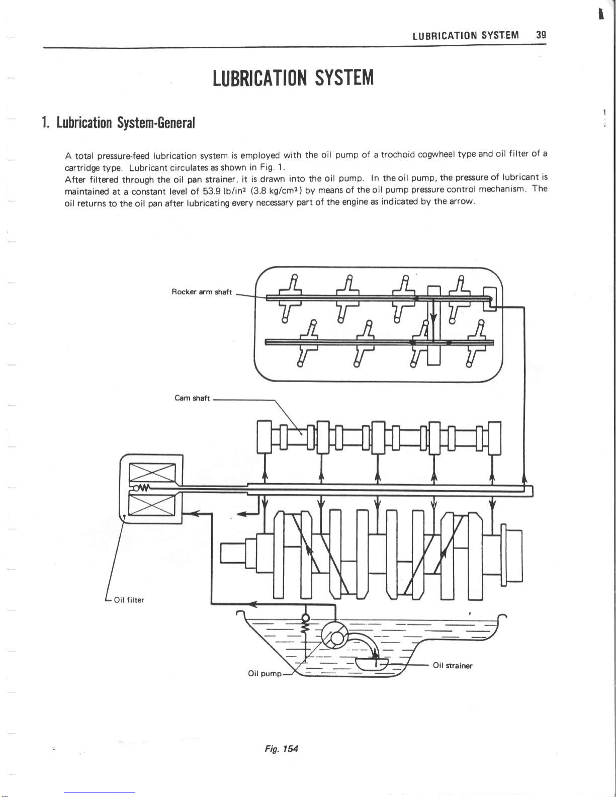
I
LU
BRICATION
SYSTEM
39
LUBRI
CATION
SYSTEM
1.
Lubrication
System-General
A
total
pressure-feed
lubrication system
is employed
with
the oil
pump
of a trochoid
coryvheel
type
and
oil
f ilter of a
cartridge type.
Lubricant
circulates as shown
in
Fig. 1.
After filtered
through
the oil
pan
strainer,
it is
drawn
into the
oil
pump.
ln
theoil
pump,
the
pressure
of lubricant
is
maintained
at
a constant
level of 53.9
lb/inz
(3.8
kg/cmz
)
by
means of
the oil
pump
pressure
control
mechanism'
The
oil returns
to the oil
pan
after
lubricating
every
necessary
part
of
the
engine
as
indicated by
the arrow.
Rocker
arm
shaft
Oil
pump
Oil
strainer
Fig. ,54

4A
LUBRICATION
SYSTEM
2"
Disassembling
the
[Iil Pump
2-1
.
Removing
the
Oil
Pump
1.
Before
disassembling
the
oil
pump
,
refer
to
"1-2,
Disassembling
the
Engine".
2-2.
Bisasemhling
the Oil
Pump
1. Remove
the'two nuts,
and
remove
the
oil
strainer
from
the
pump
cover.
Remove
the
pump
cover
(B),
outer rotor
{C)
and
pump
drive
shaft
assembly
(D)
from
the
pump
body
(A).
Remove
the
split
pin
(H).
Pull
out the spring seat
(E),
pressure
control spring
(F)
and
pressure
@ntrol
plunger
(G)
from
the
pump
body.
Note:
Take
c;rre
of
that
the
spring seat
and
pressure
control
spring
will
not
spring
out
wtren
the
split
pin
is remored.
(D)-
2.
3.
-,
Fig.
155
{A}
o
C
3. Checking, Maintenance
and
Limit
0f
Adjustment
3-l .
Checking and Adiusting
the Oil
Pump
Wash
and clean the
parts
removed
from
the oil
pump.
lnspect
the
parts
for
cranking,
heavy
damage
and
breakage. If
any
of these
parts
is found
faulty,
replace
it.
J. Clearance
between
the oil
pump
body and outer
rotor:
Measure
the
clearance
benrueen the
oil
pump
body
and
outer rotor
with
a
special
tool
(No.
N026
STANDARD
FEELER
GAUGE).
Replace
both if
'
t're
measurement
exceeds
0.0118
in.
(0.30
mm).
STD
clearance
between
|
0.00$
'^"
0.01
1 in.
pump
booy
and
outer
rotor
|
(0.20
-
0.27
mm)
Fig.
156
2.
Clearance between the
oil
pump
cover and outer
rotor:
Measure
the clearance between the
oil
pump
cover
and outer
rotor with
a
straight
scale
and a
special tool
(No.
N026
STANDARD
F
EE LE
R
GAUGE).
Replace
both
parts
if
the
measurernent
exceeds
the
maximum
limit.
Clear.
between
oil
pump
cover
and
outer rotor
STD
clearance
Max.
allow
clear
0.001g
,v
0.0039
in.
(0.04
a,Q.1O
mml
0.OO59
in.
(0.15
mm)
Fig. 157
3.
Oil
pump
cover
Check
the oil
pump
cover
bottom
(contacting
surface
with
oil
pump
body,
inner
rotor
and
outer
rotor)
.
lf
stepped
wear
is
found,
replace
the
cover. lf
the wear
is
slight, smooth
it
out.

LUBRICATION
SYSTEM
41
Fig. 158
4.
Fig.
159
5.
Pressure
control
sPring
Check
the
pressure
control
spring
for
lf
it
fails
to
meet
the
specifications
table
below,
rePlace
it.
Clearance
between
the
oil
pump
drive
shaft
as'
sembly
and
pump
body/pump
cover
bearing
Measure
the clearance
between
the
oil
pump
drive
shaft
assembly
(1
)
and
the
pump
body
l2l
and
pump
cover
(3)
bearings
(A)
and
(B)
.
lf
the
measurement exceeds
the
specif
ied
maximum
limit,
replace the
parts.
Fig.
160
3-2.
Oil
Filter
Replacement
1.
Replace the oil
f
ilter
(cartridge
type)
after
300
hours
of
operation
(First
replacement:
after
30
hours of
operation).
Replacement
must
be
made
as
an
asemblY.
2.
Oil
filter
-
removal
and
installation
a.
Use
the
special
tool
(No.
0490130
OIL
FILTER
WRENCH)
(A)
as
shown
in
Fig.
161 to
remove the
oil
filter.
b.
Apply
engine oil to
the oil
filter
gnsket,
and bolt
it
to
the
cylinder block
with a
specified
tightening
torque
'7
.2
-
10.8
ftob
(1
.0
-
1 .5
m-kg).
Note: After the
insullation,
make
sure
that
no
oil
leks.
Fig.
l6l
3-3.
Checking
and Adiusting the
Oil
Pump
Driven Gear
Shaft
1.
Remove
the
blind cover
(A)
.
2.
Check the oil
pump
driven
gear
shaft
(B)
for
damage and
breakap of
teeth.
any
defects
given
in
the
Clear.
between
drive shaft ass'y
and
pump
body
cover bearings
STD clearance
Max.
allow
clear
0.0003
-
0.0018
in.
(0.007
-
O.O47
mm)
0.0O39
in.
(0.1
mm)
Pressure
control
spring
specif
ications
Free
length
2.16U
in.
(55
mm)
Length
-
when
installed.
1.6929 in.
(43
mml
Load
-
when
installed
5.91
lbs.
t2.68
kg)

-t
42
LUBRICATION SYSTEM
4.
Assembling
0rder
+1
.
Assembling
the
Oil
PumP
Follow
the
disassembling
procedures
in
reverse.
4-2.
Mounting
the
Oil
PumP
Oil
pump
can be
mounted by
means
of the
reverse
order
for
assembling
the
engine.
(See
3-1
Assembl-
ing the
Engine
of
Chapter
Engine)
Note:
The
following-listed
engine
oils
are
com-
mendable.
Fig. 162
3.
Fig.
163
34.
Measure
the
oil
pump
driven
gpar
shaft's
end
play
by
use
of
a special
tool
(No.
N026
STANDARD
FEELER
GAUGE}.
0.002
-
0.O04 in.
Driven
gear
shaft's
end
play
I iffi|trre.l
mml
Adjusting
the
End
Play
of Oil
Pump
Driyen Gear
Shaft
lf
the
measurement of the
end
play
is not within
the
range
of 0.002
^'
0.004
in.
(0.05
^,
0.1
mm),
remove
the
drive
gear
cc'!,er
(C)
,
and
pull
out the
thrust
washer
(D)
and driven
gear
shaft.
Adjust
the
end
play
by using
thrust
washers
as
specified
below:
(F
igs.
162
and
1
63)
Oil
Filer
Specifications
Type:
Canridge
filter
Pressure
for
aditsting
1 1
.4
*
17 .1 lb/inz
the relief wlve
(0-8
'-'
|
-2
kglcrnz
)
5-2.
5. Specifications
5-1.
Oil
Pump Specificatiom
Type:
Drive system:
Rated
oil delivery:
Regulated
oil
pressure:
Trochoid
gear
Total
pressure
feed
25.36
US
pints/2,O@
rpm
(12
A2,OOO
rpm)
53.9
lb/inz
(3.8
kg/cmz
)
at
3,000
rpm
Part No.
Part Name
Thickness
01
40050
Thrust washer
0.07910.0079
in.
12.ffi.2mm)
01 40060
Thrust
washer
0.10@.0079
in.
(2.5t0.2
mm)
01
40070 Thrust
washer
0.0O4
in.
(0.1
mm)
01 40090
Thrust
wa*ter
0.07110.0079
in.
(1.8t0.2
mm)

I
43
I
b
CO
O
LING
SYSTEM
1.
Cooling
Sfstem-General
The forcedcirculation
cooling
system
is
imployed
with a centrifugal
water
pump,
four'blade
cooling
fan, and
wax'type
thermometer.
when
the temperature
of
the
cooling
water
is low,
it circulates
in the
direction
of thearrowwith
a dotted
line
in
Fig'
l
O4.
When
the temperature
is
high,
the
cooling
raater
flows
in the direction
of
the arrow
with a
solid line.
Cooling
fan
complete
Cmling
tan
,a<
{
165
3.
Take
out the
floating seat
and
cu$rion
rubber
from
the
water
pump
impeller.
COOLING
SYSTEM
{
{
Radiator
Water
pump
Fig.
l&t
L
Disassembling
Order
2-1.
Removing
the
Water
Pump
1. For
the
removal
of
the
water
pump,
refer to
"1'2-
Disassembling
the
Engine of Chapter.
Engine"-
2-2. Disasembling
the
Water
Pump
1.
Loosen
the
scr€nil
and bolt,
and
remo\re tte
end
plat
(B).
2.
Pull out
the
water
pump
impeller
(A)
by
using
the
.,
speial
tool
(No.
04901
10
WATER
PUMP
IMPE
LLER
PU
LL}.

J
COOLING
SYSTEM
4.
5.
6.
7.
8.
Pull
out the
water
pump
pulley
boss
(G)
by
using
a
press.
Remove
the
dust
seal
plate
(F).
lf
the
water seal,
ball
bearing,
etc.
are
found
defective,
perform
the
following
disassembling
proced
ures.
Pull
out
the
snap
ring
(H)
by using
the
snap
ring
pliers.
Bemove
the ball
bearing
and
water
pump
fraft
from
the water
pump
body
(D)
by
using
a
pliers.
Disassemble
tlre
ball bearing
and
water
pump
shaft
into
three
parts:
pump
straft
(El,
ball
bearing
(K)
and
spacer
(J).
For
this
operation,
use a
prs.
9.
Pull
out the
water
seal
(C)
from
the
water
pump
body.
Whenever the
water
pump
is
disassembled,
the
water seal
should be
replaced
with
a
new
one.
Checking
th
e
Thermostat
Check
the
thermostat
spring
(A)
for
cranks
and
breakage"
lf
found faulty,
replace
it.
lf
the
thermostat
valve
is
found
open,
rephe
it.
Put
the thermostat
into
water,
and
slowly
raise the
water
temperature.
Check
for
temperature
at
which
the thermostat
valw
opens.
lf found faulty,
replace it.
3'2.
Fig.
167
2.
3.
1.
Fig. 166
3.
Checking
Maintenance
and
Limit
0f
Adiustment
3-l
.
lnspection
of
Water
Pump
1.
Check
the
disasembled
parts
for
the
following-
listed
defects.
lf
any of
them is
found faulty,
replace
it.
a. Cracks
and
damage of
the
water
pump
body.
b. Cracks and damage
of the
water
pump
impeller.
c.
Play
and
noise of the ball
bearing.
"
d.
Damage
of
the
water
seal.
Valve
opening
temperature
177
*
1
83oF
(80,5
^,83.5oC)
Valve
lift
0.315
in.
or
more
at
203oF
(8
mm
or
more
at 95oC)
4. Assemhling
the
lTater
Pump
1,
2.
a.
b.
c.
d.
Follow
the disassembling
procedures
in reverse
order.
Notes
on water
pump
rsslrUling
Be sure
that the
two
ball bearings
are
placed
with
the unsealed side facing
toward
the spacer.
Feed
Albania
Grease Nos.
2 and 3
so
that
one-third
of
the space between
the
dust seal
plate
and the
ball bearing
is f illed
with
the
grease.
Slightly
apply
grease
to the contacting
surfaces
between
the
floating
seat
and
water
seal.
After
assembling
the
water
pump,
rnake
sure
that
the ball bearing
turns smoothly without
excessive
play
and noise.

COOLING
SYSTEM
45
-
5.
Mounting
the
Water
PumP
7. Specifications
1. Follow
the
removal
procedures
of
the
water
pump
7-1
. Water
Pump
-
in
reverse order.
For
details,
refer
to
"3-1.
Assembling the
Engine
of
Chapter.
Engine.
Type: Centrifugal
Notes:
Water
PumP Pulley
ratio:
1
:
0.8
r
1) Replace
all
packings
with
new
ones.
Water
seal:
Mechanical
seal
2',
Adjust
the
V-belt
so
that
it will
have an up
and down
movement of
0.55
-
0.79
in.
(14
-
20 mm).
When the
belt
is
nevv, the
7'2- Thermctat
L
slackness
*rould
be 0.43
-
0.55
in.
(11
-
14
mm).
TYPe:
Wax
tYPe
'
3) Make
sure that the
quantity
of
cooling
water
Valve diameter:
1 .'102 in.
(28
mm)
-
is 18.5
gal
(71).
Valve
opening
temperature:
180
t
2"F
(82
r
1.5"C)
Valve lift:
0.315
in.
(8
mm)
l
b
6.
lnstlling
fte
Thermosbt
Follow
the
removal
procedures
of
the thermostat.
Always
replace
the
packings.

MEMO

FU
E
L SYSTEM
47
1.
Fuel
System-General
The
carburetor
is
Nihon
Kikaki-made. Stronberg
type, 210028-061, double-venturi, single carburetor.
The
fuel
pump
is
of
mechanical
type
(PU56U),
made
by
Nihon Kikaki,
and
the
pump
rocker
arms are
operated
by
cams attached to the cam shaft.
The
gasoline
filter
is
of
cartridge
type,
which
provides
easy access to seryie,
while
the air
cleaner is of oil
bath type.
'lF
Fig.
t
68
2-2.
Ghecking
the
Air
Cleaner
1
.
check
the air
cleaner
element
(A)
for
dirt
ac-
cumulation
and
clogging.
lf
necessary,
wash
and
clean
it.
Check
the
oil
pan
assembly for
diny
oil.
lf
the
oil
is
found
dirty,
replace
it.
Check whether
the
oil
level
in
the
air cleaner
oil
pan
assembly
is
between
the upper
and
lower
level
I
ines. lf
necessa
ry
,
refill
with
oil
.
An
incorrect
oil
level will
reduce
engine
performance,
and there-
FUEL
SYSTEM
Figl
t 6e
4.
2-3.
Air
Gleaner
Specificatiom
Type:
Rated
air
flow
rate
(max.):
Cleaning
efficiency:
(lnitial
stage
-
full
tife)
fore,
the
oil
level
must
be
maintained
as specified.
The
engine
oil
should
be
used
tor retilling.
Cleaning
the
air
cleaner
element
Both
air cleaner
element
and
oil
pan
assembly
should
be
cleaned with
cleaning
solvent.
Time
lntervals
of
Element
Cleaning
Cleaning After
first
50
hours
Every
100 hours
2. Air
Cleaner
2-1.
Removing
the Air
Cleaner
Element
1.
Remove
the
clamp
(A)
from
the
air
cleaner
asembly,
and remove
the
oil
pan
assembly
(B).
2.
Remove
the wing
nut
(C)
fastening
the
air cleaner
and cap
assembly
(D),
and
remove
the cap
assembly
by
pulling
it
uprnard.
3.
Remove
the
two
wing nuts,
and
remove
the aitr
cleaner
assembly.
E
A
c-t
Oil-bath
type
4,731
.2
gal/min
(1,250
[/min)
95o/o
2.
3.
3.
Fuel
Pump
$1 .
1.
Removing
the Fuel
Pump
Remove
the
clip,
and
disconnect
the
fuel
hoses
(A)
from
the
fuel
pump
(B)
at
the
both
inlet
and
intake
sides.

ffi FUEL
SYSTEM
Fig.
l7O
3-2.
1.
2. Renrove
the two
nuts, and
remo\€ the
fuel
pump.
3.
Remove the diaphragm
(D)
and
diaphragm
spring
(E)
from the
body.
Fig.
173
4.
As
shown
in
Fig.
174,
pull
out
the
pin,
and
remo\€
the
rocker
arm
(G)
and
rocker
arm spring
(F)
from
the body.
(Fig.
173
and
174l'
Fig. ,74
3-3.
Checking
$e
Fuel Pump
1.
Checking the fuel
pump
a.
Check
the
valve
spring for
breakage
and
fatigue.
lf
the spring is
found
faulty,
replace
it.
lf
the
valve
is
found
open,
.
even
though
slightly,
it
should
be
replaced.
b. Check
the diaphragm for
breakqe,
damage
and
aging. lf
it is found
faulty,
replace
it.
c.
check the
diaphragm
spring
for
breakage
and
fatigue.
lf found
faulty,
replace
it.
d.
Check
the
rock
arm
bearings
for
excessive
pray.
(Fis.
171)
$4.
Asembling
the Fuel
Pump
follow
the
disassembling
procedures
in
r€verse
order.
Disassembling
the
Fuel
hrmp
Rernow
the
f
ive
set
scre$/s,
and
separate
the
housing
(A)
from
the body
(B).
Fig"
l7l
2.
Remove
the
two screws, and
remove
the
valve
(C)
from
the
hotsing
Fig.
In

FU
EL
SYSTEM
49
Model:
Disharge:
Fully-closed
discharge
pressure:
Suction head:
4.
Fuel
Filter
3-5.
lnstalling
the
Fuel
Pump
Follow
the
removal
procedures
in
reverse
order.
After installation,
make sure
that
no
fuel leaks.
3-6.
Fuel Pump Specifications
found
faulty,
replace
it as
a
unit
assembly.
When
replacing
the
f
uel
f
ilter,
make
sure
that
it
is
installed
correctly
in
direction
and
no
fuel
leaks.
O
our
Fig.
175
3.
Time
intervals
of
fuel
filter
replacement
Fuel
filter
should
be
replaced
every
300
hours
of
operation.
Mechanical
A32
pint/min
at
low speed
(150
cclmin
at
low speedl
lN
Q
1.5
pint/min
with
full-open
(700
cclmin
with
fullopen)
1
.42
^'
2.13
lbs
linz
(0.
t
^,
| .5
kg/cmz
)
19.7 in.
(500
mm)
1.
The fuel
f
ilter
is
of the
cartridge
type.
2.
The
fuel filter is
not
required to be
clerred.
lf it is

50
FUEL
SYSTEM
5, Carburetor
$1. Construction
Air
Bent
Pipe
lvlain
Air
Bleed
Chalk
Valve
ttlhin
Nozzte
\
Pump
Arm
Link
pump
Rod
SPring
Damper
Spring
Piston
Shaft
Piston
Leather
Pump
Piston
lnlet
Check
Valve
Outlet
Check Valve
Pump
Nozzle
Large
Venturi
Small
Venturi
Throttle
Valve
Fis.
176
Main
jet
circuit
The
construstion
of the
main
carburetor
system
is
as shown
in
fig.
176. The fuel flowing
out of
the
f
loat chamber
is
meered
by
the
main
jet
and
mixed
with
the
air
f lowing from
the.
main air
bleed
emulsion
hole, then
jetted
into
the
air
stream at
the
narrowest
zone
of
the
venturi.
The
main
carburetor
incorporates a double-venturi,
wherein
the
large
venturi
has
the
small
venturi
skirt
at
its
narrowest
portion.
The
speed
of the air
flow
is
extremely
high
at
the
narrowest
portion
of
the
small
venturi,
and
accordingly,
the
quick
atomiza-
tion of
fuel
can
be asured.
Fuel
consurnption
is
also
economized
Slow
speed
circuit
The
fuel
pasing
through
the
main
iet
is
metered
Slow
Port
ldle
Port
by the
slow
iet,
and
mixed
with
the
air
flowing
from
the
No. 1
air bleed
iet
located
near
the
slow
jet
end.
This.atomizes
the air-fuel
mixture, which
is
further
metered
by the
slow
economizer.
The
metered
air-fuel
mixture is
mixed
with
the
air
stream
from
the
No.
2 slow air bleed
jet
positioned
on the
top end
of
the
vertical
slow
passage,
and
further
atomized, then
flowing
to the
slow
port.
The
slow
port
has
a
goundshaped
hole
and
positioned
on the
side wall
of the
main
bore
near
the throttle
valve. The
fuel
is
jetted
through this
slow
port
when
the
engine runs
with low load.
While
the
engine runs
idle,
the
fuel
is supplied
through
the
idle
port
located
on the
intake
pipe
side of the
slow
port.
ln
general,
the
air-fuel
mixing ratio for
engine
idling
varies
depending
on
the
engine,
and there-
Second Slow Air Bleed
Ja
First
Slow
Air
Bleed
Jet
I
I
Pump Connecting
Rod
It
Slow
Economizer
ldle
Adiusting
Scrwv
--Strainer
Float
Valve
Sea
\*inJet
Float
Valve
F
loat
Pin
Float
.--/
/
Float Room
1.
2"

FU
EL
SYSTEM
51
fore,
the
id le speed
ad
just
screw
is
provided
to
regulate
the
ratio.
The
optimum
opening
of
the
idle
speed
adjust
screw
is the
position
where
the
adjust screw
is
backed
off
1-1
12
turns
from
the
fullyclosed
position.
The
slow
jet
has
a
very small
hole
measuring
0.017
in.
(0.42
mm)
in
diameter,
and
therefore,
it
is
easily
clogged
with
f
ine
dust.
The
slow
jet
is
designed
to
be
removed
with
a
screw
driver,
providing
great
convenience
to
service-
4.
3.
Float
circuit
The f loat
system
consists
of
the
f
loat
valve
and
the
float,
and
its
purpose
is
to
maintain constant
the
level
of
fuel
in
the
float chamber.
The
fuel
which
is
fed from
an
mechanical
fuel
pump
at
a
pressure
of
1
.42
A,
2.13
lb/inz
(0.t
-
0.15
kg/cmz
)
is
filtered
by
the
strainer
located
at
the
carburetor
inlet,
and
flows into
the
float
chamber
through
the
clearance between
the
float
ralve and
the
valve
seat.
As
the f uel
level
rises,
the
float also
rises,
and the
f
loat
valve
moves
upward
accord
ingly.
ln this
way,
the
float valve is
finally
forced tightly
against
the
rnalve
sat, thus stopping
the
fuel flow
to
the
float
chamber.
Then, if the
fuel level
drops,
the
float
moves
down
and
releases
the
float valve
so
that
the
fuel
inlet is
opened.
ln
this
manner,
in
actual operation,
the
f
uel
is
maintained
at
a
practically
constant
level.
The
float
level of this
carburetor is
0.616
t
0.039
in.
(15.5
mm
t
1)
above the
body
top.
Therefore, the
carburetor
can
be
tilted
14o
at
maximum
so that
it
provides
smooth
engine
start
and
idling on
a slope.
Fig.
177
The
float chamber
vent is
provided
immediately
before
the
choke
valve; that
is,
it
employs
the
inner
vent
system.
This
prevents
the air-fuel
mixture
from
becoming
rich
due to
the clogging
of
the
paper
filter
element.
The f
loat
is
made
of
oil-resistant
foamed
rubber.
"
Unlike
a conventional
type
f
loat,
it is not
hollow-
ed.
Therefore,
there
will
be
no
troubles
resulting
from
faulty
soldering.
Faulty
soldering
allows
f uel
to
enter
the
inside
of
the
float, letting
it sub-
merge.
Further,
float and
needle
valve
are
in-
corporated
in
the
float chamber
to
ensure
that
the
f loat
level
can
be
constantly
ma
inta
ined at
a
ceftain
position.
Overflowing
caused
by
the
ex-
cessive
vibration
can
be
protected
by
means of the
hole
on
the
f
loat.
Acceleration'pump
c
ircu
it
The
acceleration-pump
circuit
includes
a
vacuum
piston
linked
to
a
throttle
valve,
and
consists
of a
pump
piston,
inlet
check
valve,
outlet
check
valve
and
pump
nozzle.
The
.1.mp
piston
is separated
into
two
sections,
which
is
connected
by
a
pin
fitted
in
holes
in
the
piston
shaft,
and
is
provided
with a damper
spring.
Accordingly,
when
the
pump
piston
comes
to
contact
the
cylinder
bottom,
the
pump
rod is
pushed
by
the
pump
arm.
Then the
damper
spring
contracts,
and as
a
result, the
pump
arm
and
throttle
rnlve operate
so
that
the
valve
becomes
fully
opened.
When the
throttle
valve
quickly
opens
from
the
fully-closed
position,
the
pump
piston
is
pushed
downward
by
means
of
the
pump
arm,
connecting
rod,
and
pump
arm
link
connected
to
the throttle
valve
rod.
The
fuel
under
the
piston
causes
the
inlet
check
valve
to
close,
thereby
stopping
the
reverse flow
of
fuel
to
the
t
loat
chamber.
As a result, the outlet
check-valve opens
and
the
fuel is
sprayed
into
the
air stream
through the
pump
jet.
The acceleration
fuel is
sprayed to
the
narrowest
area of the
large
venturi, where the
air
flow
speed
is
highest,
and
accordingly,
the
atomization of
f
uel
is
made
easy
When
the throttle
valve
closes
from
the
fully-
opened
position,
the
piston
moves
up and
the
pressure
under
the
piston
becomes
negative.
This
rnakes the
inlet
check valve
(in
the
float
chamber)
open,
and
the
.fuel
in
the
float
chamber
is
drawn
out.
Then,
the outlet
check valve
closes
and
prevents
the
reverse flor
of
air
from
the
pump
jet.
ln
this
way,
the acceleration
pump
correctly
operates.
A
spring
is
inserted
between the
pump
rod
and the
upper
body, and
prevents
the excesive
play
of the
pump
rod
link and
pump
arm. lt
also
prevents
Two holes
are
provided
on the side
opposit
to
the
pump
piston,
and
the
fuel
spray amount
can be
chagned by
inserting
the
connecting
rod
into
the
inner
hole
or
the
outer
hole.
ln
general,
the acceleration
spray amount
of
f
uel
varies
according
to the
operating
conditions
of the
engine
as
well
as
to
the conditions
of
climate.
.9;
oF
sltr
Se
dg
6.669
in.
(17
mm)
1.OO4
in.
(25.5
mml

FUEL
SYSTEM
Normally,
the
amount
of
fuel
spray
is less
in
summer
than
in
winter.
With
the
connecting
rod
in
the
outer
hole, the
pump
spray
rate
is
0.000528
pt
(0.3
cc)
per
stroke
throughout
the
v@r,
but
when the
rate
has
decreased
due to
the
wear of
the
pump
leather
and
other defects,
the
inner
hole should
Oe
used
for
optimum
spray
q
uantity.
As
mentioned
earlier,
this
carlruretor's
pump
nozzle
also serves
as
auxiliary
fuel
sr/stem.
When
the engine
runs
at
high
speed
or
with
high
load,
a
large amount
of
air
is
required and
the
neptive
pressure
affmting
the
pump
nozzle
raises
the
outlet ctreck
valve
weight.
The fuel is
drawn
out
through the
purnp
nozzle
and
mixed
with
air.
The
pump
weight
overcomes
the
negative
pressure
until
the
amount of
air
drawn
in reaches
a
certain
level,
and causes
the
chgck
valve to
close.
Thus
stops
its
rrrork
as auxiliary
fuel system.
5.
Surting
system
The
starting
system
of
this
carburetor
includes the
choke
valve
linked
with
the choke button
on
the
dash board
and
the
fast idle
system
coupled
with
the
choke valve.
When
the
choke
button
is
pulled,
the
choke
lever,
which
is
linked
by
a
cable, is also
pulled,
thereby
closing
the
choke
valve.
The
choke
valve
is
attached
to
the
choke
valve
shaft
with
two screws,
which
is
positioned
eccentrically
in
relation to
the
a
ir
horn.
The
choke
valve shaft
is
coupled
with the
choke
lever by
means of
the choke
valve
spring.
The
choke
lever
is
fitted
with a
link.
When
the
choke
lever
is
pulled,
the
link
makes the throttle
lenrer open
so
that
the
opening
is suitable
for
starting.
Then,
if
the
starter
is
turned,
a
rich
mixture
is obtained,
and
ea$/ starting
is
assured.
When
the
engine
is
started,
the
vacuum
in
the
inlet
pipe
increases
and
the
choke valve, being
affected
by
negative
pressure,
overcones
the
spring ten-
sion.
ln this
stage,
the
choke valve
opens
properly
so
that
the
over
choke
is
prwented
and
the
engine
continues
sunning.
As
the
engine
is
rmarmed up,
the
choke button
is
depressed
to
open
the
choke
valve
properly.
After
the
engine
is
fully
vrarmed
up, the
choke
rralve
fully
opens
and the
thronle
valve
opens
to
a
specified
idl
ing opening.
The use of
the
choke
valve in
the
position
closer to
the
closed
position
will
result
in
greater
fuel
consumption.
when
you
stop
your
tractor
wh ile
travelling,
depress
the
choke
button
as
far
as
the
engine
will
not
stall.
*2.
0isasembling
the hrburgtor
Notes:
On
carburetordisasernbling
Place
the
rerpve
parts
ordsly
so that
you
will
not
confuse about
ttrem
when
performing
reasembly.
Clean
all
ttre
remowd
parB
with
gsoline.
Bloru
evry;mall hole in
parts
with compressed
air
to
remove
dust
O
Never
clean
jets
and
small
holes.
R emoving the carburetor
Loose the
hose
band,
and
remove
the
hot
air
hose
(A)
.
Remove
the
connecting
bolt
(B)
,
and
rernove the
fuel
hose.
Pull
out the
vacuum
advance
hose
(C),
and
remove
the
rod assembly
(D)"
Remove the two
nrounting
nuts
(El,
and
remove
the carburetor
from
the
inuke
manifold.
o
o
1.
cl ,
b.
c.
d.
Fig.
178

FUEL
SYSTEM
53
Removing
the link mechanism
Remove
the
throttle
return
spring
(A).
Remove
the
split
pin,
and
remove
the
choke
connecting
rod
(B)
from
the
throttle
lever.
Remove
the split
pin
,
a
nd
remove
the
pump
connecting rod from
the
pump
lever
(C).
Fig.
179
3.
Removing
the air horn
a.
Remove
the
pump
return
spring.
b.
Remove
the
five
screws,
and
remove
the
air
horn
from
the body,
together
with
the
float
and
needle
valve"
Fig.
180
4.
Removing
the
f loat valve
and
f
loat
a.
Pull
out
the
f
loat
pin
f
rom
the
air
horn,
and
remove
the
f
loat.
(night
in
Fig.
181
)
b.
Remove
the
valve
spring
and
needle
valve.
(Left
in
Fig
181
)
Fig. l8l
5.
Removing
the accelerating
pump
Pull
out
the
aaelerating
pump
piston
assembly
i
from
the
body.
Fig.
,82
6.
Removing
the air
bleeds
and
iets
Remove
the
slow
air
bleed, slow
jet,
rrrain
air
bleed,
injet
chek
valve
and
power
jet
from
the
body,
as
shown
in
Fig.
183.
2.
a.
b
c.
#
T
(Al
Slow air
bled
(B)
Slow
iet
(C)
Main
air bleed
Fig.
183
(D)
I
nlet
chtrk vatrre
(E)
Power
jet

il
FUEL
SYSTEM
To
remove
a
nd
insta ll
the
po\
/er
jet,
use the
special
tool
(No.
0490120
POWEH
VALVE LOCK
DR
I VE
R).
7.
Removing
the
body
Remove
two
mounting
screws,
and
remove
the
body
from
the
throttle
chamber.
tu
8.
Removing
the main
jet
Renrove
the
plug
(A
from
the
body, and
remove
the
main
jet
(Bl
as
strown in
Fig.
185.
Check the
throttle
shaft
bearing
for
wear
and
throttle
valve
for
smooth
operat
ion.
I
f
any
of
these
is
found
faulty,
reBlace
it.
Checking
and
repairing
the
bodY
Check
the body
for
cracks
and
deformation
of
contacting
surface
with the
air
horn and
throttle
chamber.
lf it
found
faulty,
replace
it.
Check
the
main
iet,
slow
air
bleed,
slow
jet
and
power
jet
for
clogging. Check
the air
passages
and
fuel
psages
for
clogging.
lf
necessary, clean
or
replace.
Checking
the repairing
the link
mechanism
Check
the
levers, arms,
and connecting
rods for
deformation,
bend
and
wear.
lf
any
of
these
is
found faulty"
replace it.
Adjusting the throttle opening
linked with starting
The
choke
valve
is
linked with the throttle
valve
(A)
,
and therefore,
when
the
choke button
is
f
ully
pulled,
the
choke
valve is
fully
closed
and
the
throttle
valve
opening
will
be
suiuble
for
starting
opening
is
139
-
17o
.
When
the
choke valve
is fully
opened, the clear-
ance
(A)
of
the
throttle
\€lve
on
the
primary
side
should
be
0.039
in.
(0.91
mm). lf
not,
adjust it
mrrectly
by bending
the
choke
connecting rod
*
(B).
Fig.
186
6.
Adiusting
the f
loat
level
a.
Remove
the
air horn
from
the
carburetor,
and
raise
the
f
loat
(A)
.
b. slowly
lower
the
float
(A)
and
stop
it
when
the
float
seat
(C)
contacts
the needle
valve
stem
(B).
Meazure
the
c,
and
if
the
measurement
is
0.16 in.
(4.0
mm),
the
float
level
is
correct. lf
not,
adjust
it
by
bending
the f loat
seat .
I
3.
a.
b.
4.
5.
Fig.
:a-
Fig.
185
53.
Checking,
Mainunance
and
Limit of
Adjustment
Checking
the air horn
Check
the
air
horn for
cracks
and deformation of
contacting . surface
with
the
body. check
the
choke
valve
shaft
bmring
for
wear.
Check the
choke
valve for
smooth
operation.
Check the
f
loat
for
damage
and
deformation.
Check the
needle
valve
for
contacting surfaces
between the
valve
and
seat.
lf
any
of these
is
found
faulty, replace
it.
Checking
the throttle
chamber
Check
the
throttle
chamber
for
cracks and
da
formation
of
its contacting
zurface with
the body.
1.
2.
A'0.035 in.
10.91
mm|

FUEL
SYSTEM
55
Fig. 187
7.
ldle
speed
adiustments
For
idle
sped adjustments,
be
used.
Adjustments are
throttle
adjust screw
(A)
and
54.
Asembling
the
Garburetor
For
the d
isassembly
procedures
in
reverse order.
Note:
O
Replace
the
packing
with
a
new
one.
O
After
assembling,
make
sure that
the
throttle
valve and
choke
valve
operate
smoothly.
5-5.
Mounting
the Garburetor
Follow the
removal
procedures
in reverse
order.
$6.
Specificatiom
Model
21AO28 - 061
Construction
Stronberg
type
Draft direction
Downward
draft
Outlet diameter
1.O24
in.
(28
mn$)
Venturi
0.732
x 0.256
in0
(18.6
x 7
mmOl
Ma
n
let
#77
Ma
n air bleed
#50
Slow
iet
#11
Slow
air
bleed
Pr
124
Pz
17O
Power
jet
#45
Pump
injector 0.0236
in@
(0.6
mmO)
Needle
valve
0.059
inO
(1.5
mmo)
Float
level 0.61m.mg in.
(15.5t1
mm)
Throttle valve
10o,
0.059 in.
(1
.5
mm)
tn ict
a
tachometer
should
made
by
using
the
idle adjust
screw
(B).
Fig. 188
a.
b.
c.
d.
Fully
turn
in
the
idle
adjust
acrew, and
back
it
off
3
turns.
Then
screw in
the
throttle
adjust screw 2
or
3.
turns,
and start the
engine
Sloly
back out
the
throttle
adjust
screw,
and
the
engine speed will slow down.
Stop turning
the
screw
just
before
the
engine
begins
to
run roughly.
Then
slowly
turn
in
the
idle
adjust screw.
When
the
engine
begins to
run
smoothly
at
maximum
speed,
stop
turning
the screw.
Slow down the
engine speed
by turning out
the
throttle
adjust screw.
,
Repeat
this
operation
so
that
the
engine
will
smoothly
run
at 700
-
800
rpm.
Note:
Do
not
turn
in
the
idle
adjust screw
too
hard,
otherwise, the
screw end will
be damaged.
6.
GoYernor
Sl .
Governor
System
-
Genenl
The
KSP
gpvernor,
made
by
Koshida
Shoko
K.K.,
is
of
the
mechanical
type. lt
is
used, being
interlocked
with
the
Stronberg
type
carburetor
Q1W28l061)
for
the
PB
engine.
The
governor
is
operated
by
f
ly-weight
centrifugal
force,
and
its
adjustment
can be
done
accurately
according
to the
engine
specif ications.
E
ngin
e S
pec
if ications
:
Specified
engine
speed
2,800
r.p.m.
(25
PS)
Static
speed variation
12o/o
or less
Momentary
no-load
variation
17o/o
or les
Note:
The
governor
has
been
adjusted
most
suiubly for
engine
operating
conditions,
and
therefore,
you
should
make
no
attempt
to
disas-
se.--r$lq it,
except
for
oiling
it
or
for
repairing
Criticril-defects.

56 FUEL
SYSTEM
6-2.
Governor
-
0peration
and
Construction
1.
Operation
The
governor
detects
the difference
between
the
actual
engine
speed
and the specif
ied
engine speed,
and
contro
ls
the carburetor's
throttle
valve
to
adjust
the
engine
speed
to the
specif
ied value.
As
the engine
sped changes,
variation
occurs
in
fly-weight
centrifugal
force,
and
according to
the
variation,
the
governor
spring
length varies.
As
a
resu
lt,
th
is
variation
changes the
throttle
valve
opening
by means
of
the
link mechanism,
thereby
changing
the engine
speed.
GOVERNOR
TEVER
(5T
}
2. Construction
(
Refer
to
F
igs.
1
89,
1
90 and
1
91
).
The
governor
shaft
(5)
,
which
is locked to
the
governor
pulley
(6),
is
provided
with
two balance
weights
(9).
The
balanceweights
are
constantly in
contact
with
the thrust bearing
collar
(13)
,
to
which
the
thi'ust
bearing
(31)
is
f
itted.
The
thrust
bearing
is
designed to
move
back and
forth
on the
governor
shaft
(5).
One end
of the thrust
bering
(31)
is
in
contact
with
the
fork
lever
(381
attached
to
the
fork shaft, and
variation in
centrifugal
force
is transmitted
to
the
fork
lever
shaft
(5).
ADJUSTING
LEVER
I42I
STOPPER
BOLT
I22I
GOVERNOR
SPRING
(45}
-]
O'J
o\
\O\
\o
SPR|NG
BI)LT
l44l
Fifi.
189
Side
Weu-

FUEL
SYSTEM
57
NUT
(20}
FORK
LEVER
SHAFT
(37}
GEAR
CASE
(62}
FoR@
GOVERNOR
SHAFT
(5}
GOVERNOR
PULLEY
(6}
BALANCE
WEIGHT
(9}
/
I
Fig.
,g)
*ctionl
View
THRUST BEARTNG
COLLARjfII\
For
Tractor
Mgter
Fig:
I9l &aiornl
Vievvs A
and
B

58
FUE
L
SYSTEM
3.
Construction
of control
mechanism
64.
Maintenance
The
governor
spring
(45)
is
hooked
on
the
spring
bolt
(zl4)
which
is attached
to the
fork shaft
(5)
To keep the
governor
in best
condition,
proper
and on
one
of the adjusting
lever
'42)
.
Variation
oiling is
required,
and
no other
service
is neces-
in
centrifugal
force
affects
the spring bolt
(44),
sary. Oiling
should
be
made as
folloras:
and
thereby the
length of the
governor
spring
(45)
a.
Use the
same
oil
as
for
the
engine.
I
is changed.
b.
Replace
the oil after
50
hours of operation,
and
thereafter,
replace
it every
100
hours.
4. Construction
of link
mechanism
c.
Oil
quantity
should be
0.01
gal
(40
cc).
ThegovemorlEyer(51
)
isboltedtotheforkstraft
Feedtheoil sothattheoil
level isatthelower
(37),
and
the
lever
has
the
ball
joint
(interlocked
level
line
marked on thepuge.
(Thequantitywill
with the carburetor)
on
its
end.
be about
0.01
gal.
(40
cc))'
According to
variation
in output
at the
detector,
the
governor
lever
(51)
moves up
and down,
and
controls the throttle
valve
opening
by
means
of
5-5.
Intedock
Adiustment
between
Carburetor
and
the
link
rod.
thereby
regulating
the
engine
speed. Governor
The
interlock
adjustment
is rbguired only
when
6.3.
Purpose
of
Govemor
Adjustner8
the
gowrnor
is found to
be
faulty because of
instable
engine
speed,
fluctuations
in specified
Note: The
adjustment
procedures
as
described
in
engine sped
and increases
in speed
variation.
athis
section is
applicable
only
when the
governor
a. Turn
in the
throttle adjusting
screw
to bring
the
itself is
required
to be
adjusted.
Accordingly,
throttle
valve opaning
to zero.
when
the
governor
is
ncessary to be adjusted
in
b.
Fully
pull
out the
adjusting
lever, and loosen
the
relation to the carburetor,
refer
to
"5. Adjusting
govemor
lerrer
not so that the t'rrottle
valve
lnterlocking
betwen
C,arburetor
and Governor"
opening
will be betwen
7Oo
and
75".
which will be discused
laler.
c.
Return
the
adiusting lever to
its
original
position,
It should be noted that the
go\rernor
ha been
and adiust
the
fork
lever
stopper so that
the
';
properly
adjusted
before the tractor
is shipped
throttle
adiusting
valve will
return
to the
zero
out from th€ factory.
ln
Fig.
189, the double
position.
circle
I
@
shows sealing by
pinch,
and
the
d. By using the throttle
adjusting
screw
and
the idle
circle
(O
indicates the
position
painted.
Avoid to
adjusting screrru,
perform
idle
speed adjustmeng.
make an attempt to
adjust unnecessarily.
O
ldle
adlusting screw . . . Adjust so that the
\racuum
gauge
reading will be at maximum.
1.
Adiustingenginespeedasspecified
O
Throttle
adjusting
screw .. .
Use a tacho-
Adjustmena can
be
made
by cfranging
the tension
meter.
of the
governor
spring
(45).
The
spring
tension
e.
Adjust
the
adjusting lever
position
by using
the
can be
changed byvaryingthelength.of
thespring
stopper bolt so
that
the
engine
speed
will
be at
by turning
in
or out
the stopper
bolt
(22)
attadled
3,150t50 r.p.m.
with
no
load and
with f ull
.
to the
adjusting
lever
1421.
To incresetheengine
throttle.
speed,
the spring
length should
be
made
longer,
Note:
Disasembling of the
whole
governor
while to decrease
the sp€ed,
it should
be
storten-
should
be done by
its manufacturer,
and therefore,
ed.
the disassembling
procedures
are not described
herein.
2.
Adjusting
speed
variation
Speed
variation adjustments
can be
done
by
changing
the
lengith
of
the
spring bolt
(44).
when
'
the
projected
part
of
the spring bolt
is
longa,
speed
variation
becornes
greater,
while the
part
is
shorter, speed
variation
is smaller.
lf
the
spring
bolt
is adjusted,
the
specif
ied engine speed
is also
changed,
and
therefore,
readjustment
is
required

FUEL
SYSTEM
58-1
6-6.
Governor
-
Troubles
and
Remedies
1.
The
troubles
of
the
governor
can
be classified
into
the following
four types:
a.
Hunting
-
periodic
variation
of
engine speed.
b.
Variation
of
specif
ied
engine
speed.
c.
lncrease
of
fluctuation
coeff
icient.
d.
lnoperative
governor.
2. Causes
of
troubles
and
remedies
a.
Hunting
-
periodic
variation
of
engine
speed
b.
Variation
of specified
engine
speed
Cause
Remedy
I
ncorrectly
adjusted
governor
spring.
Readjust.
c. lncrease
of
fluctuation coefficient
d.
lnoperative
governor
6-7.
Govern0r
Disasembling
Procedures
1. Remove
the
governor
from
the engine
a.
Remove
the ball
joint
at the
end
of
the
governor.
b.
Remove
the
nut
at
the
front
of the
pulley,
and
remove
the
pulley.
c.
Remove'the bracket
mounting
bolts, and
remove
the
governor
assembly.
2.
Disassembling
the
governor
assembly
a.
Remove
the
gear
case stud
nut,
and
remove the
gear
case
k
id.
b.
Pull
out
the
drive
gear
roll
pin,
and
remove the
drive
gear.
c.
Remove
the
counter-sunk
screw
at
the
f
ront
of
the
governor
case.
d.
Hold
the
governor
case
flange
with
your
hand,
and
lightly strike
the
governor
shaft
projecting
to the
governor
case
rear side
with a
hammer.
The
gover-
nor shaft
kid and
bearing
case
kid
can
be
removed.
Disassembling
the
governor
shaft
kid
Pu
ll out
the
thrust
collar.
The
bearing
case
kid
can be
re-
moved
in such
a
man-
ner as
shown
in the
photo.
Do
not
attempt
to
further disassemble
the
removed sections.
Necessary
check
can
be
made
without
per-
forming
further
dis-
assembling.
4.
Disassembling
the
governor
shaft kid
a.
Remove
the bayonet
set-screw
on
the
rear
of
the
weight
holder.
The
governor
shaft
kid can
be dis-
assembled into
the weight set
pins,
weights,
and
weight
pins,
in
that
order.
b.
Remove
the taper
pin,
and
the
weight
holder
can
be
removed
with ease.
5. Disassembling the
bearing case kid
a.
Remove
the
snap ring,
and
disassemble
the bearing
case kid
in
order
of
the
oil
seal
and
bearing.
3.
a.
Cause
Remedy
Fatigued
gwernor
spring.
lncreased
friction
on
link
mechanism.
Excessive
wear
on
link
joints.
Replace.
Clean
and
oil.
Replace.
Cause
Remedy
Lack
of
lubrication.
lncreased
friction of
moving
parts.
oil.
Disassemble
and
check.
Cause
Remedy
Damage
and seizure
of
inner
parts.
Disassemble
and
cfieck.

58-2
FUEL
SYSTEM
d.
6.
Disassembling
the
governor
case
kid
a.
Pull
out
the
lever
joint
cotter
pin
located on
the
bottom
end
of
the
adjust
lever.
b.
Remove the adjust
lever
snap
ring.
The
governor
case
kid
can be
disassembled
into
the
adjust
lever,
governor
spring,
spring
bolt,
and
lever
rod,
in
that
order.
c.
Remove the spring
bolt
holder
taper
pin,
and
the
bolt
holder can be
pulled
out
with
ease.
Loosen the
governor
lwer
f
itting
bolt,
and
remove
the
govemor
lever.
Remove
the
fork
lever
fit-
ting
ten
pin
in
the
case.
Lightly strike
trre
fork
*raft
projecting
into the
case
(on
the
bolt
holder
sidel
witlr
a
hammer, and
trte
fork lwer
can be
removed.
One
half
of the
lwer
is attached
with fie
oil
seal and
bearing.
7. Disassembling
the
gear
case
a.
Remove
the
sleeve,
and
the
driven
gear can be
removed.
6-8.
Parts
-
lnspection
a.
When
the
governor
shaft
kid
is removed
from the
governor
case,
inspection
should
be
started
b.
lf
any
parts
are
found
damaged
,
scratched
or
excessively
worn,
they
should
be
replaced.
c.
The tolerance
of
main
parts
is
as
follows:
(lf
any
parts
are
found
in
excess of
tolerance,
they
should
be
repaired or
replaced.)
T.
Name
of
Part Measuring
Point
Specif
ied
Dimensions
Tolerance
Fork
shaft
Wear
on bearing
contacting
surface
as74loz4o-o'00019685
'--o.ooo5bl
18
In'
(0.520i3?lmm)
-0.0007874
in.
(-0"02
mm)
Bend of shaft
0
0.0007874
in.
(0.02
mm)
Fork
lever
pin
Outside diameter
0.3149fu
t0.0019685
in.
(8o
10.05
mm)
-0.003947
in.
(-0.1
mm)
Weight
set
pin
Outside diameter
a236zzol:3ffi3:313
in
, A
-0.009
'
t@
o.01,
mml
-0.0007874
in.
(-0.02
mm)
Bend
0.0003937
in.
(0.01
mm)
0.001 181
1
in.
(0.03
mm)
Weight
Pin
Outside diameter
0.3149fu
10.0019685
in.
(Bo
t0.0b
mm)
-0.003937
in.
(-0.1
mm)
Thrust
collar
Wear
inside
diameter
0.433070
(1
16
+0.00106299.
0
ln'
+0.0017
_0
'mm)
+0"001
181 1
in.
(+0.03
mm)

FU
EL
SYSTEM
58.3
Name
of
Part
Measuring
Point
Specif
ied
Dimensions
Tolerance
Balance
weight
in.
Wear
on bush
inside diameter
A.23622o
(60
+0.00047244
0
ln'
+0.012
0
mm)
+0.001
1811
in.
(+0.03
mm)
Governor
spring
F ree
length
2.48031
10.019685
in.
(6310.5
mm)
+0.019685 in.
(+0.5
mm)
Spring
constant
5o/o
23.039
lb/in.
5o/o
(
''-
)
'2.0
kg/mm
-5%
-50/
lnitial
tension
1 5.435
lbrl .103
(7.010.5
t
g)
-1
.103
lb
(-0.5
kg)
Governor
shaft
Wear on thrust
collar
contacting
surface
o4330r,1:3ffi33i33in
(1
1p
-3:319
mm)
-0.001
181
1
in.
(-0.03
mm)
Wear
on
bearing
contacting
surface
o3e37o':33ffJ3ff;
(1oo
-3:?3
mm)
-0.0007874
in.
(-0.02
mm)
Bend of
shaft
0
0
0.0007874
in.
(0.02
mm)
6-9. Asembling
Procedures
1.
For
assembly,
the disassembly
procedures
should
be
followed in reverse
order.
2.
Assembling notes
a.
Thoroughly wash
all
disassembled
parts
with
light
oil.
b.
Be
sure
to
replace all
gaskets
and oil seals
with
new
ones. Otherwise
oil
leakage
may
result.
It
is
also
advisable
to
replace
bearings
as
a
rule.
c.
When
press-f
itting
the bearing
case k
id into the
governor
shaft,
grease
the
oil seal
inner surface
and
bearing
side surface.
d.
When
installing thrust collars, apply
a
small
quan-
tity of
mobile
oil
to contacting
surfaces.
e.
Feed
a
plenty
of
f iber
grease
into
the
gear
case.
f.
Tighten the
pulley
with a
torque
of
36.25
ft-lb
(5
kg-m).
g.
When
replacing
the balance
weights,
make
sure
that
new weights are
the
same
in
mass
as old
ones.
h.
Make sure
that
the
governor
lever
is
at an angle
of
4o
to
the
horizontal
line.
i.
Set
the spring
bolt so
that the distance
from
the
center
of
the spring
bolt
holder
to that
of
the
spring
hole
i5
0.1024
in.
(28
mm).
j.
Make
sure
that
the
runout
of
the
pulley
V
groove
is
0.0098
in.
(0.25
mm)
or
less
measured
from
the
governor
case
mounting
surface, after
assembling
is
completed.
6-10.
Adiusting
the Governor
1.
lnstalling the
governor
assembly
a.
When
installing the
governor
on
the engine,
be
sure
that
the
V-belt
is
flexes
0.55
-
0.78
in.
(14
-
20
mm)
(in
case
of
tension
of
some22.05
lb
(10
kg))
by
depressing
with
fingers
midway between
the
pulleys.
l{ the
belt
is
a
new
one, adjust
the
f lexion
of
the belt to
0.55
-
0.67
in.
(14
-
17 mm)"

58.4 FUEL
SYSTEM
2.
Adjusting the specif
ied engine speed
6-1
1.
Lubrication
a.
Adjustment can be done by turning
the adjust
lever
stopper
bolt and
by changing
the
governor
lt
is requested
to supply
lubricant
(Engine
Oil)
spring tension. lncreasing the
length
of
the
spring
in
the
volume of
approx.
0.0
1
gal.
(0.04
lit.)
installed
causes
the
engine
speed to increase,
and
The standard
oil
level should
be
read
on
the top
shortening causes the speed to
dbcr""r". position
of
the oil
level
gauge
when
it is
fully
b.
Adjusting
speed
fluctuation
coefficient
inserted.
Adjustment
can be done by
changing the distance
from
the
center
of
the spring bolt
holder to
that
of the spring hole. When
the distance is
longer,
the coefficient
is
larger.
and
vice versa.
3.
Correcting
periodic
speed
variation
a. lf
hunting
(to
slight
degree)
is found,
it
should
be
adjusted
by
the
damper
spring attached
to
the
lever
rod
end"
b. lf
hunting
is
phenomenal
,
governor
adjustment
is
incorrect.
Readjustment
should
be
made by
ad-
justing
the
specific speed and
fluctuation
coeffi-
cient,
alternately.

IGNITION
SYSTEM
59
IGNITION
SYSTEM
1. Spark
Plug
1-1
.
lnspection
and
Adjustment
of
Sprk
Plug
1.
Clean
the
plug's
electrode
with
a
plug
cleaner
tester.
Fig. 192
2.
Check
the spark
plug
for
the
following and
if it is
faulty,
replace it.
a.
Whether
the
insulator
is
damaged.
b.
Whether
the electrode
is worn.
c.
Whether
the
Easket
is
darnagd.
3.
Measure
the
plug
gap
with
a
plug
gap gauge.
Any necessary
adjustment
;an be
made
by
bending
the
plug's
outer
electrode.
Sparking
plug
clearance
|
0.031 in."(0.8
mm)
1-2.
Spark
Plug
Specifications
TYPe:
Plug
gap:
2.
Distributor
B6E
(NG
K)
W2OEP
(DENSO)
0"031
in.
(0.8
mm)
2-1
.
RemoYing
the
Distributor
1
.
Remove the
primary
coil
from
the
distributor.
2.
Remove
the
high tension
mde
from
each
spark
plug.
3.
Remove
the
vacuum advance
hose
f rom
the
vacuum
control asembly.
4.
Unscrew
the
distributor
securing
nuts and
lift
up
the distributor.
2-2. Disasembling
the
Distributor
Disassemble
the
distributor
is
in
the
procedure
out-lined
below.
Remore
the
distributor
cap
(A)
and
pull
off
the
rotor
(B).
Remove
two
vacuum
control asembly securing
screw
bolts,
and clips
securing
the
link
to the
breaker
base asembly, and then
the vacuum
@ntrol
asembly
(C).
Loosen
the
nyt
(D)
at the
primary
coil terminal.
Remove
the breaker
asembly and two
breaker
arm support
securing
screw
bolts,
and lift up
the
breaker base
(E)
and breaker arm support
(F).
Remove
the condenser
(H)
from
the housing
asembly
(G).
Pull
off the
pin
holding
the drive
gear
(J)
and
shaft
asembly
(l),
and
remove
the
drive
gear
and shaft
assembly
(K)
frorn
the
housing
assembly.
Pull
off the cam
(L)
from
the
shaft assembly.
1.
2.
3.
4.
tr
\.r.
6.
*
Fig.
193
7.

60
IGNITION
SYSTEM
J
Fig.
l%
8.
Pull
off the
clip connwting the
shaft
asembly
to
the
governor
weight, and remove
the
governor
weight
(M)
and
governor
spring
(N).
Contact
arm spring
tension
Measure
trre
contact
arn
spring
tension
with a
spring
tension
tester,
and
if
the
measured
value is
not satisfactory,
replace
it.
1.1
-
1.4
lb
Contact
arm
spring
tension
I
f
dgb
^,
OSO
gl
See whether
the
drive
gear
teeth are
cranked,
damaged
or broken,
and if
it is faulty,
replace
it.
I nspecting
dovral angle
Measure
the dowel
angle
with
a
disributor
tester.
lf
the
measured
value
is not in
the
following
range,
it
is
assumed
due
to
inconect
point
gap,
uorn
cam,
worn
contact
arm heel,
deflected
contact
arm,
etc.
See what
is
the
trouble,
and if it is
faulry, correct
or
replace it.
5.
2-3
Checking,
Maintenance rnd Limit
of Adius0nsnt
Check ing th
e
d istri
butor
Distributor cap
Check
the
distrbutor
cap
for
crack,
split or
damage,
and
if
it is
faulty, replace
it.
lf the
high
tension terminal
is corroded,
scrape it
off.
Rotor
Check the
rotor
for
crack
or
darnage,
and
check
whether
the tip
of the terminal
is
burnt.
lf
it is
faulty, replace
it.
Contact
point
Check
the contact
point
for wear,
burnt
pan
or
sticking.
lf
it
is
only slightly
damaged,
grind
it
with
an oil stone,
while
if
swerely
damaged,
replace
it.
Condenser
Meazure
tre condenser
caprcity
with
a
condenser
tester,
and
if it is faulty,
replace
it.
Condenser
capacity
|
0.2O
-O.24pF
1.
2.
A
J.
6.
7.
4.

IGNITION
SYSTEM
61
Dowel
angle
I
S6
-
610
t96
8.
Adjusting
the
point
gap
a. Set
the
contact arm
heel to
the
high
part
of
the
cam
so
that
the
clearance
between
points
becomes
widest.
b.
lnsert
a special tool
(No.
N026
STANDARD
FEELER
GAUGE)
into
the
point
gap
and
measure
the
point
gpp.
To
adjust
the
point
gap,
loosen
two
scrqnts
and
adjust
the
point
gap
and
retighten
the screws.
Point
gpp
|
0.019
'v
0.020 in.
lO.4
-
0.5 mml
Fig.
197
24.
Asemhling
the
Distributor
Follow
the
reverse
procedure
of
"Disassembling"
2-5.
Mounting
the dbtributor
Follow
the
re\/erse
procedure
of
"Removing".
Note: After
installing
the distributor,
adjust
igni-
.,
tion timing
with
a
timing
light.
2-6. lgnition
Timing
lnspection
and
Adiustment
To inspect
and
adjust
the
ignition timing,
use
No.
1
cylinder
together
with
the
timing
light and
tachometer.
Connect
the
timing
light
secondary
coil
to
No.
1
spark
plug,
and
each
primary
coil
to the
battery
terminals
(+)
and
(-).
Connect
the
techometer.
Start
the
engine
to
reach
the ordinary
idling
revolution of
700
-
800
rpm.
See the timing
mark
with the
timing
light.
It is
good
if
the
T
(timing)
mark
notch shown
in
Fig.
198
is aligned to
the
indicator
pin
end.
To
adjust
the
ignition
timing,
loosen the distribu-
tor
lock
nut
and
move
the distributor
properly.
Retighten
the
lock nut
and
agnin
inspect
the
ignition timing
with
the timing
light.
Fig.
198
2-7 . Dlstributor
Specifications
1.
2.
3.
Fig.
4.
5.
6.
Type:
Point
gap:
TVD-4MR
0.016
-
0.020
in.
(0.45
*
0.05 mm)
Point
pressure:
1.1
^,
1.4
lb.
(500
-
650
g)
Condenser
capacity
.
O.ZhrF
t10%
lgnition
clearance:
90"
+
15o
Dowel
angle:
58.5"
t
3"
(distributor
axle)
lgnition
order:
1-34-2
..-4.'54,rU-{
v
,7
i7,',TA
c-
Jrl-'
|
(
o

MEMO

TROU
BLESHO OTIN
G
63
TROUBLESHOOTING
Symptom
&
Possible
Cause
1.
The Engine Lacks
Power
1-1. Fuel
Compresion
is
lnsufficient.
1
2
3
4
5
6
7
Valve
clearance
improper.
Valve
seat
leaky.
Valve
stem
stuck.
Valve
spring
weaken
or
broken.
Cylinder
head
gasket
leaky.
Piston
ring
stuck
or broken,
Piston
ring
or
cylinder
worn.
Adjust
the
clearance.
Smooth
contacting
surface
with
valve.
Replace
guide
and
valve.
Replace valve
spring.
Replace
gnsket.
Replace
ring.
D isassemble
engi
ne
and.
correct.
1-2.
lgnilion
Timing is lnconect
1
|
lgnition
timing incorrect.
(Early
or
late)
|
Adiust ignition timing.
2
|
Spark
plug
faulV.
I
Clean and correct
or replace spark
plug.
3
I
Distributor
points
faulty.
I
Correct
or
replace
points.
1-3.
Fuel
Level
is
Low
1
|
Carbilretor clogpd. Disassemble
and
clean carburetor.
Clean
pipe.
Check
joints
and
retighten.
Correct
or
replace
pump.
Replace
fuel filter.
2
|
Fuel
pipe
clogged.
3
|
Fuel
system oDntains
air.
4
|
Fuel
pump
in
poor
condition.
5
|
Fuel
filter
clogged.
14.
Carburetor
Drayrn lnsufficient
Amount
of
Air
Air
cleaner clogged.
Clean air cleaner.
l
-5.
Engine
Overheats
1
|
Cooling
water insufficient. Add water
2
I
V-belt loose
or
slipery.
Adjust
or
replace
belt.
3
I
V-belt worn
or broken.
3
I
V-belt worn
or broken.
I
Replace V-b€lt.
q
I
Thermostat inoperative.
I
nepuce
thermostat.
5
|
Water
pump
inoperative.
5
I
Water
pump
inoperative.
I
Disasemble
and correct
pump.
0
|
Radiator
clogged or
leaky.
I
Ctean and correct
or
replace
radiator.
7
|
lgnition
timing
incorrect.
Adjust
timing.
2.
Fuel Consumption
is
Excessive
2-1
.
Engine
Oil Leaks
1
2
3
4
5
6
Oil
pan
drain
plug
loose.
Oil
pan
set
bolts
loose.
Oil
pan packing
faulty.
Oil seals
faulty.
Cylinder
head
gasket
broken.
Oil
filter
set bolts
loose.
Retighten
plug.
Retighten
bolts.
Replace
packing.
Replace
oil
seals.
Replace
gasket.
Retighten
f
ilter
set
bolts.

TROUBLESHOOTING
J
Symptom
&
Possible
Cause
-"n-*
7
I
Rocker arm
cover
packing
faultY.
Tim
ing
chain
cover
pack
ing
f
au
lty.
R
eplace
pack
ing.
Replace
packing.
1
I
Piston
ring damaged.
Replace
piston
ring.
Adjust
end
gap.
Replace
ring.
Replace
piston
or
cylinder
liner.
2
|
Piston
ring
end
gap
incorrect.
3
|
Piston
ring
worn
or
stuck.
4
|
Piston
and
cylinder
worn.
2-2.
Oil Comes
Up
into the
Combustion
Chamber
2-3.
Oil
Comes
Down
from
Valve System
1
I
Valve
seat
worn.
Replace
valve
seat.
Replace
valve and
valve
guide.
2
I
Valve
stem
and
valve
guide
worn.
3.
Engine
b Hard
to
Shrt
3-1.
Engine
has Surting
Difficulty
Replace
oil
with specified
brand.
Charge
battery.
Replace
battery.
Clean
and
tighten
terminals.
Replace cables.
Disassemble
starter and
correct
or
replace.
Adjust clearance between
cam
and
snritch,
or
replace sruitch.
Engine
oil
too
thick"
Battery discharged.
Battery capacity low.
Battery
terminal
connection
faulty.
Starter
faulty.
Safety
sritch
faulty.
1
2
3
4
5
6
3-2. lgnition
System is DefectiYe
r
I
Distributor
points
faulty
I
Correct
or
replace
points.
2
|
Point
gap
incorrect.
I
Adjust
point
gap.
3
I
Spark
plug
gap
incorrect.
3
I
Spark
plug
gap
incorrect.
I
Adjust
spark
plug
gap.
4
|
Spark
plug
cord loose or
faulty.
I
Tighten cord connection
or
replace.
5
I
lgnition
coil
faulty.
I
Replace
coil.
6
|
Primary
winding
connection
faulty.
I
Check
and
retighten
connection.
-7
|
Condenser
faulty.
I
Replace
condenser.
3-3.
Engine
34.
Carburetor
Valve
seized
up.
Piston,
piston
ring
or
cylinder
worn.
Cylinder
head
gasket
broken.
Correct
valve
or
replace.
Disassemble
and correct.
Replace
gasket.
1
|
Choke
valve
faulty.
Correct
or
replace
choke
mechanism"
Adjust.
Disassemble
and clean.
Retighten
bolts.
2
i
ldle
speed
circuit
faulty.
3
|
Carburetor
clogged
or too dirty.
4
I
Carburetor
mounting bolts loose.

TROU
BLESHO
OTIN
G
65
Symptom
&
Possible
Cause
Remedy
4. Engine
is
iloisy
+1
.
Piston
I
I
Piston-to-cylinder
clearance
excessive due to
worn
I
Replace
piston
and
cylinder
liner.
cylinder.
Z
I
Piston-to-piston
pin
clearance excesively
large.
I
Replace
piston
and
piston
pin.
3
|
Piston
ring
broken.
I
Replace
piston
ring.
4
|
Piston
seized
up.
I
Replace
piston.
+2.
Crankslraft
t
I
Oil
clearance excesively
large
due
to
worn
main
I
Replace
bearing
metal.
bearing
metal.
2
|
Crank*raft
journal
worn.
I
Machine
crankshaft or
replace.
3
|
Main
bearing
metal
damaged.
I
Replace bearing meul and
check lubrication
system.
&3.
Connesting
Bod
M.
Miscellaneous
Replace
bearing
metal.
Correct
or
replace
rod.
Machine
crank
pin
or
replace.
Replace
bearing
metal
and
check
lubrication
system.
Oil clearance
excessively
large
due
to
worn
con-
necting
rod
bearing
metal.
Connecting rod
bent.
Crank
pin
worn.
Connecting rod
bearing
metal
damaged.
1
I
Valve
clearance incorrect.
Adj
ust clearance
correctly.
2
I
Crankshaft
thrust
washer
worn. Replace
washer.
3
I
Engine
oil
level
low.
Add
engine
oil or disassemble
and
correct engine.
5-1. lgnition
System
5-2. Air-fuel
Mixture
lgnition
system wiring
connection loose.
Spark
plug
faulty.
lgn ition
tim
ing
incorrect.
5.
Firing
lnegularities
Check connection
and
correct.
Clean
spark
plug
or correct,
or
replace.
Adjust
timing.
Clean
and
adjust
carburetor.
Clean
and
adiust carburetor.
Clean
or
replace fuel
pipe.
1
I
Valve
clearance
incorrect.
1
|
Valve
clearance
incorrect.
I
Adjust
valve
clearance.
Z
I
Valve stuck.
I
Oisasemule valve,
and correct
or replace.
3
|
Valve
spring
weak.
I
Replace
spring.
Air-fuel
misture
too
lean.
C,arburetor
clogged.
(or
dirty)
Fuel
pipe
clogged
or dirty.
5-3. Valves

TROUBLESH
OOTITUG
-t
Symptom
&
Possible
Cause
Remedy
4
Valve
tim
ing incorrect.
Adjust
valve timing.
Carbon
build-up
in
combustion
chamber.
Cylinder
head
gnsket
leaky.
6. lnconect
ldle
Speed Adiustment
54. Cylinder
Head
Remove carbon.
Replace
gasket.
6-1.
Carburetor
Readjust
idle
speed.
ldle
speed
adjustment
incorrect.
6-2.
Air En&ring
Fuel
Line
1
I
Air
enters carburetor
fuel
line.
Retighten carburetor
mounting
bolts.
Replace
gasket.
2
|
lntake manifold
gnsket
faulty.
6-3. Valves
1
|
Valrae
clearance incorrect.
I
Adjust rralve clearance.
2
|
Valvetovalve
seat contact
not
perfect.
I
Smooth
out
valve.
3
|
Vatve
stem-tGvalve
guide
clearance
excessively
I
Replace valve
and
rralve guide.
large.
6-4.
Cylinder
Hmd
1
I
Cylinder
head
gasket
leaky.
Replace
gasket.
7
"
Engine Runs
not
Smooilrly
(when
accelrated)
7
-1.
Carburetor
C.arburetor
accelsation
pump
circuit
clogged.
Spark
plug
faulry.
H
igh-tension
wire
faulty.
Distributor
point
gap
adiustment
incorrect.
lgnition
coil
faulty.
7-3.
Engine
1
|
Valve
seized up or
adjusted
incorrectly.
I
Readjust
or replace.
2
|
Compression insufficient.
2
|
Compression insufficient.
I
Disassemble engine
and
adjust.
3
|
Cylinder
head
gpsket
leaky.
I
Replace
gasket.
D
isassemble
carburetor and correct.
Disassemble
carburetor and correct.
7-2. lgnition
System
Clean spark
plug
or
replace.
Replace
wire.
Adiust
point
gap
or
replace
points.
Replace
ignition
coil.

SATOH
TRACTOR
I
\
al
MoDEL
s,65OG
REPAIR
MANUAL
CTUTCH
SYSTEM
PUBLICATI0t{
Jlo.03-B

I
t
-
CONTENTS
CLUTCH
SYSTEM
1 .
General
2. C,onstruction
3. Disassembling
Order
3-1
.
Disasembling
Order Using
"
A"
Method
3-2.
Clutch
Asembly Disassembling
Order
3-3.
Disassembling
Order
Using
"8"
Method
34. Clutch
Pedal
Mechanism
Disasembling
4. Assembling
{Adiusting}
Order
4-1
.
Clutch
Pedal
Mechanism
Assembling
+2. Clutch Assembly
Assembling and
Fitting
+3.
Overall
Assembling
lrspection,
Maintenance
and Limit
of Modification
Troubleshooting
G1.
Clutch Slips
. .
6-2.
Clutch Drag
6-3.
Shudder
when Starting
il.
Clutch Overheat
Specif
ications
5.
6.
1
1
1
2
2
2
2
4
5
tr
5
7
B
I
I
I
I
10
107.

CLUTCH
SYSTEM
1.
General
The
clutch
for
the
S-650G
is
of
a dry
single
plate
lever
type.
Each
component
of
the
clutch
is
made
not
to
degensate or
be damaged
due
to the
sliding
abrasion
of
the
clutch
disc
in case
of
connection,
moreover,
to
bear a
shock in case of disconnection
or
a
sudden
load in case
of
change
in
transmission
torque.
The
operation of the
clutch
is
smooth
and
secure
and
provision
is made
for
keeping
it
from
being
worn
or
damaged
due to
repeated use.
This
clutch has
the
following special
systems
in
order
to transmit securely
a
great
torque.
2. Construction
When
the
clutch
pdal
(A)
is depressed
forwards,
the
shaft
(B)
is caused
to
rotate,
the
fork
secured to
the
shaft
with
cotter
pins
slides
in
the
arrow direction to
push
the thrust
bearing
carrier
(D),
forcing
the
thrust
bearing
(E)
into
contact
with
the
release
lever
(F),
the
CLUTC}I
SYSTEM
Six
pressure
springs
are
used,
enabling a
high
pressure
to
be
applied
to
the
clutch disc
to
transmit
the torque
completely
and
evenly.
For
the
material of
the
clutch
facing,
a
wire-
reinforced
woven
fabric whose
constant
of
friction and
shape
are
hardly changed
even
at a
high temperature.
Besides,
on
the
facing there
are
radial
grooves
0.03
in.
(0.8
mm)
in depth
and
0.07
in.
(1.8
mm) in
width, thus
preventing
the temperature
rise
of
the
facing,
incrasing
its durability
and
making it ea$/
for
the
clutch
to
be
releaed.
release
lever
is
pushed,
the
Bressure
plate
is
sh
ifted
toward the
transmission
by
the
pressure
of
the
pressure
spring
(G),
the
clutch
disc
is
disengaged, the
drive
from
the
engine is cut
off.
(a)
(b)
t
ll
k
A
B
c
D
E
F
G
H
I
J
clutch
pedal
shaft
fork
thrust bearing
carrier
thrust bearing
release lsrer
pres$rre
spring
pressure
plate
clutch
disc
f
lywheel
Fig.
I
Cltttch
Meclnnkm

-t
CLUTCH SYSTEM
3,
Disassembling
0rder
To
dismount
the clutch
assemb
ly
f rom
the
"tractor,
there
are two
methods
for it, which
to take
depend-
ing
on
the
facilities
of
its repair
shop.
A
Method:
Dismounting
method
when
the
repair
shop
has
heavy repair
tools
such as
a
chain block.
B
Method:
Dismounting
method
when
the
repair
shop
has light
repair tools.
C"aution:
ln
dismounting
the
clutch asembly,
it
should
be done
on
a broad,
f
irm and
flat
ground
as
the
transmission
is
detached
at
its connection
with
the engine
assembly
and
each component
is
very
heavy.
3-l
. Disasembling
0rder Using
"
A"
Method
1.
ln A MethoC,
the
front
wheel
axle
and the
engine
are
removed
before
removing
the
clutch assembly
(see
REPAIR
MANUAL,
ENGINE,
1.
Disasembl-
ing
Order,
1-1. Removal
the
Engine
(No.
1
^'
21l,
"
2. Support
the
removed
engine
with
a special tool
(0490010
ENGINE
STAND) or
in
other
ways.
3. lnsert
a special
tool
(1
102T01
CLUTCH
DISC
PILOT)
into the clutch
asembly
center
and
put
an
alignment
mark
both on
the
f
lywheel
and
the
clutch asembly
(to
avoid an
improper fitting in
the case
of
reassembly).
4.
Unscrew
four
clutch asembly
set
bolts and
t\o
reamer
bolts,
and
remove
the clutch
asembly
together
with the disc
from
the
flywheel.
3-2. Glutch
Asemhly
Disasembling 0rder
1
.
Attaoh the
clutch
cover
asembly to the special
tool
(11O2TO4
CLUTCH
RELEASE LEVER
DIS-
ASSE MB
LY
TOO
L)
(see
Fis.
2l
.
2. D iscription of
F
iS. 2
The
clutch
cover
asembly
taken
from
the
f
ly-
wheel
is
as shwon
in
dotted
lines
(
1
)
,
howevs,
under this condition
a
force which
pushes
up the
clutch
co\€r acts on
the
lever nut
(F)
and
it is
impossible to
loosen the
lever
nut
properly.
So, tighten
the bolt
(A)
of
the special
tool
(1
102T04)
to
lower the
clutch cover
assembly
down
to
a solid
lines
Ql
.
Then
the
release
lever
(E)
is set
free
and
the lever
nut can
be
easily taken
.,,
out
after
r€moving
the
cotter
pin.
Fig. 2
Dissembling
by use
of a
Drsassembling
Tool
3.
Tighten
the bolt
to
set the
asembly
to the
position
Ql
and
remove
the cotter
pin
of
the
lever
nut
(F)
and
unscrew three
lever
nuts
(F)
and
remove the
release
lever
(E)
from
the
lever
bolt
(J).
Slowly
loosen
the bolt
(A)
to
remove it
from
the
base
(D),
and
remove
the
clutch
cover.
Remove
six
pressure
springs and
lift
up
the
pressure
plate
f
rom
the
base
(D).
3-3.
Dlsasembling
0rder Using
"8"
Method
ln
B
Method,
the
front
wheel
axle, the
engine
and
the
frame
are
deuched
from
the clutch
housing
and
the
engine
f itted
place.
Follow the
proced
ure,
referring
to
R E
PA
I R
MANUAL,
ENG
lN
E,
1
. Disassembling
Order,
1
-
1
.
Engine
removal
INo.
1
^.,
10)
"
Set
the
iack iust
below the
clutch
housing
and
put
a
piece
of
wood between the
jack
and the
clutch
housing
(to
avoid a
slip).
Jack
up the
clutch
housing
to
keep the
tractor
rear
half
horizonta
I when
the
f ront wheel and the
engine are
detached,
but
the tractor
must not
be
lifted.
-
Condition
before
tightening bolts
Condition
ready
for
disassembling
A
bolt
B
washer
C clutch
cover
claw
D
base
E
release
lever
F
lenrer
nut
G
release
washer
H
clu tch cover
I
pressure plate
J lever bcllt
t
1.
2.
3.

CLUTCH
SYSTEM
Fig. 3
Front View
Deached
4.
Drive
in
a
wedge
(A)
as
shown
in Fig.
4
to
keep
the
tractor
secure.
The
wedge
must
be
a
f
irm
piece
of
lucod
of about
6 in.
(about
150
mm),
and
see to
it
that
thewedge
will
not be
removed during
operation.
Fig.
4
Wedge
(A)
5.
To
hold
the
engine oil
pan
to
the
gnrage
jack,
use a
special tool
(1102T03
OIL
PAN RECEIVER
FOR
CLUTCH
REMOVAL)
as
shown
in
Fig.
5.
When
using
the
garage
jack,
the
tractor
must
not
be
lifted
u
p.
6.
Unscrew
six
nuts
(M
1
0)
securing
the
engine and
the
cl utch
assemb
lY .
As
both
nuts
inside
the
chasis
(see
Fig. 6)
are
very
hard
to
be
unscrewed,
use
a
special
tool
(BT-100
DOUBLE
OFFSET
BOX
WRENCH
SET).
Fig.
6
Positions of
Nuts
lnside
Chassis
7.
Take
out
the
starter
motor
wiring,
and
loosen
t\40
starter
motor
securing
bolts,
and
remove
the
starter
motor
from
the
engine
cylinder
block.
8.
Loosen
eight
bolts
(Ml6
x
40)
at both
sides
of the
chasis.
Fig.
7
Remotnl
of
hrt
of
Chasis
9.
Unscrew
four
bolts
(M16
x
40)
(C)
shown in
Fig.
8.
Unscrew
three
re;,r
plate
securing screws
(M6
x 12)
(A)
and
pull
down the
rear
plate.
A
Garage
jack
B
1
102T03
C Chassis
Fig.
5
Oil
Pan Holding
Oil
pan
Front
wheel
axle
D
E

CLUTCH SYSTEM
A
Position
of rear
plate
B Chassis
C
Bottom
position
Fig.
8 lnsalling
Bolts
of
Chassis
10.
Now
the clutch
housing
and the
engine body
are
removed,
however,
if
the
chassis
is not
completely
pulled
off the
clutch
housing,
loosen the
nuts
(A)
at both
sides shown
in
Fig.
9.
rig.
9 Nut
(A)
Position
Set up
the
garage
iack
a
little
to
keep the
tractor
horizontal,
slide
the
jack
forwards
and
the tractor
is
divided
into trnp as shown
in
Fig.
3.
Note:
The engine
body
for
the
5-650
is
made
of
alminum.
lf
you
treat
the
tractor
roughly
when
sliding
the
jack,
the
stud bolts
in
the
engine
body
may
be
twisted,
and at
last
the
engine
may be
damaged,
therefore,
be
very
careful.
12. Support
the
removed
tractor
rear half
with a
rigid
rack
instead of
the
iack.
13.
To
remo\€
and disassemble
the
clutch
asembly
fitted
to
the
flywheel
wh ich has
been
removed
together
with the
front wheel axle and
the
engine,
refer to
3:1
.
Disassembling
Order Using
A
Method
3. and
3-2. Clutch
Asembly
Disassembling
Order.
34.
Clutch
Pedal Mechanism
Disasemhling
1.
Remove
the spring
with
pliers
and
then
remove
thrust
bearing
carrier
with
the
thrust
bearing
from
the
support
snout as shown
in
Fig.
10.
lf
the
thrust bearing
is again
used,
do
not
wash
it.
Fig.
l0 Removal of
Thrust Bearing hrrier
2"
Remove
the circlip
(A)
,
the
liner
(B)
,
the
clutch
pedal
(C),
the
spring
clutch
shifter
metal
(D),
and
the
"O"
ring
(E)
from
the
shaft
(G)
with
a
special
tool
(S-O
SNAP
RING PLIEnS).
Then
drive
out the
key
(see
Fig.
11).
11.
A
Circlip
B
Liner
C
Clutch
pedal
D
Metal
E
"o"
ring
F
Key
G
Shaf
t
Fig.
ll
Pedal
Mshanism
H
I
J
K
L
M
Taper
pin
Fork
pin
Roller
Nut
Cotter
pin
Fork
FK

CLUTCH
SYSTEM
\
"{-
'&',
/'
'*.L
3.
Pull
out
the
shaft,
referring to
Fig. 12.
To
remove
the
fork
from
the
shaft,
pull
out
two
taper
pins
(H)
shown
in Fig.
11
with
a
special
tool
(
17OOTO3
SPR ING
P
IN INSTALL
AND-OUT
TOOL),
pull
out
the cotter
pin
(L)
,
unscrew the
nut
(K),
and
remove
the
roller
(J)
and
the
fork
pin
(t).
Fig. l2
Removal
of Shaft
+2.
Clutch
Asembly Asembling
and
Fitting
C DE
F
Flywheel
Clutch L:over
PrssJre
plate
Lever
nut
Lever bolt
Release washer
Return
spring
4.
Assembling
(Adiusting)
Order
+1 . Glutch
Pedal
Mechanbm
Asembling
1.
Follow
the
reverse
procedure
of
"Clutch
Pedal
Mechanism Disassembling",
seeing
Fig.
1 1. ln
this
case
use
nerru taper
pins
(H).
2. Clean
the
fork
pin
(l)
and
shaft
(G)
sliding
parts
and apply
grease
to them.
lf the
snout
and
thrust
bearing
carrier
sliding
parts
are
considerably
worn, correct
or
replace
it.
7
o
t
A
B
c
D
E
F
G
H
R
ivet
I
Release lever
J
Clutch
disc
K Spring
cap
L
Pressure
spring
M
Lever
seat
Fig.
l3
Clutch
assembly

CLUTCH
SYSTEM
a.
b.
2.
1
. Before
assemb
I
ing the
clutch
assembly, check
the
fo
llowing.
Put
the
pressure
spring
(L)
to a
pressure
test,
and
ensure
that
the
spring
meets
the
following
require-
ments.
Spring
pressure
(length
when
checking)
146.67
lb.
(67.5
tg
)
Length
when
checking
the spring
1.58
in.
(40.6
mm)
c.
No f
low
on the
pressure
plate
To
reasemble
the
clutch
assembly,
follow the
reverse
procedure
of
3-2.
Clutch
Assembly
Dis-
assembling
Order
with
use of
a special
tool
(1102T04
CLUTCH
RELEASE
LEVER
DISAS-
SEMB
LING
TOO
L)
,
however, as
for
the
cotter
pin
for
the
lever nut
(D)
,
put
in
the
cotter
pin
after
setting
the
height
of
the
release
lever
(l
).
Note:
A washer
rnery
be
needed
to
the
pressure
spring
after
grinding
the
pressure
plate.
ln
every
case,
adjust
the total
pressure
upon the
three
release levers
to
be
825.99
lb.
(375
kg).
See
whether
oil
is
attached
to the clutch disc
(D).
When
using
the
removed clutch d
isc,
if
the
measurement
A
shown
in
Fig.
14
becomes
over
0.078
in.
P.2
mm), replace
it.
The measurement
A
of
a
nqr/
clutch disc
is 0.039
-
0.043
in.
(
1
.0
^.'
1.2
mm).
A
Engine
Front and
Back
Dir*tion
of
Di*
When
fitting
the
clutch
assembly
assembled
in
the
flywheel,
put
the assembly
in
the
right
place
recorded in
the item
(3)
of
3-1 . Disassembl
ing
Order Using
A
Method, especially
fit
two
reamer
bolts
to their
right
place
anci tighten them dia-
gonally
at the
torque of
13.0 f
t-lb.
(1
.B kg-m).
After f itting
the
clutch
assembly
measure
the
height
of
the
release lever
with a
special
tool
(
1
1
O2TA2
CLUTCH
RELEASE HEIGHT
GAUG E). ln
this
case be sure to turn
up and
down
the
release
lever
several
times.
The
adjustment,of
the
release
lever
can
be
made
with
the
lever nut
(D)
shown
in
F
ig.
13,
and
finally
made
after
putting
in
the
cotter
pin.
Fig.
16
Release
Lever
and
Gauge
Fig. l5
5.
J.
6.
B
A
0.078
in.
{0.2
mm}
B Clutch
disc
Fig.
14
Clutch
Disc
C Rivet
D
Cushion
plate
4.
See
whether
oil
is
attached
to the
flywheel.
lnsert
a
special tool
(1102T01
CLUTCH
DISC
PILOT)
together
with
the
clutch disc
into the
ball
bearing
in the center
of the
f
lywheel.
ln
this
case
set the
clutch
disc as shown
in
Fig. 15.
*l
Fig. 17
U*
of
Gauge

:
ll
CLUTCH
SYSTEM
4-3.
0verall Asembling
After
the
clutch
asembly
is
f
itted
to
the
engine
and
the clutch
pedal
mechanism to the
clutch
housing,
fit
the engine
and the housing,following
the
reverse
procedu
re
of
the
section
3.
Disas-
sembling
Order
Using
A
Method
or B
Method.
Then
adjust the clutch
pdal
play.
This
adjustment
is
important
when setting
the
clearance
between
the
clutch
release lever
and
the
thrust bearing.
Loosen the
nut
(A)
shown
in Fig.
18,
and
fully
tighten
the adjusting
screw
(B).
Pushing
the clutch
pedal
(D)
f
ully
to the
f
loor,
return
the
pedal
till
the
adjusting
screw
(B)
gets
in
contact with
the
shoulder
(C)
,
rotate the
pedal
by
one
turn
in
the
arrow
direction,
and
lock
it with
the
nut
(A).
Th
is
ad
justment
serves
to
control the
clutch
pressure
spring
just
before
the total
pressure,
and
the operating
length
of
the
release lever is 0.39
in.
(10
mm).
A
Nut
C Shoulder
B
Adjusting screw
D
Clutch
pedal
Adjusting
Clutch Pedat
As
the
grease
n
ipple
is
f
itted
under
the thrust
bearing
carrier,
remove
the
adjusting cover
below
the
clutch
housing
and
apply
grease.
Then
push
the
clutch
pedal
several
times
and
check
the clutch
pedal
for normal
operation
or
any strange
sound.
1.
2.
?
{
Fig.
t
8
2
\)'

8
CLUTCH
SYSTEM
5.
lnspection,
Maintenance
and
Limit
of
Modification
lnspection
Ma
intenance
Limit of
Modif
ication
1 Faulty
operation
of
thrust
bearing
carrier spring
lf
trouble
lies
in
bearing
carrier,
see
item
4-1
at
4.
If carrier
does
not
return due
to spring
load,
replace.
2
Wear
in clutch
disc
lf
measurement
A in
Fig. 14
becomes
over
0.078
in.
(0.2
mm),
replace.
3
Hardened
clutch
d
isc
Grind.
4
Oil on clutch disc
R
eplace.
5
Roll
of
clutch
disc
Rotate and
check
at
d
isc
tip.
lf
over
0.03
in.
(t
mm),
replace.
6
F
law
on
clutch
pressure
plate
Grind.
Up to
0.007 in.
rc.z
mm).
ln
this case
adjust
the
shim
so that
the
pressu
re
spr
i ng
tota
I
pressu
re
may
be
825.99
lb.
(375
kg).
This
pressure
also
applies
in
the
case
of
grinding
the
fly-
wheel.
7 Length
and
pressure
when
check
ing
pressure
spring
Adjust shim
for
adjusting
pressure.
Length when checking
1.583
in.
(40.6
mm).
lf
pressure
is within
146.67 lb.
(67.5
kg)
,
replace.
B
Height
of
release
lever
Adjust lever
nut.
1.81
in.
(46
mm)
from
flywheel.
Height
allowance
of
three
levers 0.01
in.
(0.4
mm)
I
Release
lever
operating
length
lf
over
0.39
in.
(10
mm),
trace trouble.
10 Release
bearing
Note:
This
can not
be
washed.
Rotate
it with
a
hand
and
if
any strange
sound and
irregular
rotation
are
found,
replace.
11
Clutch
pedal play
Determine
the
play,
using
release lever.
Make
sure that
it
is
within
1.57 in.
(40
mrn).
I
I

GLUTCH
SYSTEM
9
6.
Troubleshooting
6-1.
Clutch Slips
Caution:
lf
the
clutch slips, the engine
power
deteriorates
and the
fuel consumption
increases.
6-2.
Clutch Drags
6-3. Shudder
when
Starting
Trouble
Remedy
No
clutch
pedal play. Adjust
lever
nut
of
release
lever.
Oil on clutch disc.
Replace.
Wear
in
clutch
disc.
Replace.
lrregular
height
of
release lever.
Readjust within
allowable
limit
0.01
in.
(0.4
mm).
lncorrect
release
lever
return.
As lever seat which supports lever
is
worn and the
lever
drags,
correct it.
Weak
pressure
spring
lf length is
less
than
1.583
in.
(40.6
mm) in
the
case
of
1
46.67
lb.
(67.5
kg), replace.
lf
total
pressure
is less
than
825.99
lb.
(375
kg),
replace.
Trouble
Remedy
Release
lever
height
exceedingly
shorter than
the
specif
ied.
Readjust
it
to
1.81
in.
(46
mm).
lf it
is
due to worn
disc,
replace
disc.
Disc
considerably vibrates.
Replace
if it
exceed
ingly
vibrates,
or
if vibration
exceeds
allowable limit
0.03 in.
(1
mm).
Rust
due to
oil shortage
in
disc
spline
groove.
Scrape
away
the
rust
and
apply
grease
thinly.
Trouble
Remedy
Hardened
disc surface.
Grind
it
with
sandpaper
or
replace.
Exceed ing d isc shudder.
Rep lace.
Release lever
height
not uniform.
Adjust.
Rust in disc spline
groove.
Correct
and apply
grease.
Loosened
or damaged
tension spring.
Replace.

1O CLUTCH
SYSTEM
J
64.
Clutch 0verheat
Trouble
Remedy
Burnt
release
bearing.
Replace.
No
clearance
between
release
lever and
release
beari
ng.
Adjust
release
lever
height.
7.
Specificatisns
I
I
Type
Clutch disc
material
Disc dimensions
(outer
diameter
x
inner
diameter
x depth)
Static
transrn
ission
torque
Release
bering
Operation
Pressure
spring
pressure
(when
checking)
Pressure
spring
length
(when
checking)
Pressure
spring total
pressure
Number
of
pressure
springs
Pressure
spring
collar
Release
lever
maximum
operating
length
Release lever
height
Reamer
bolt
reamer
diameter
and number
Dry
single
plate
lever
Wpe
Wire-reinforced
woven fabric
7 .26 x 5.00
x
0.3
in.
(184.2
x
127 x
7.5
mm)
100.9
ft-lb.
(1
5.0
kg-m)
Non-l
ubrication
system
Foot
operating
146.67
lb"
1.583
in.
826.50
lb.
0.39
in.
1.81
in.
0.35
in.
sYstem
67.5
kg)
40.6
mm)
375
kg)
(10
mm)
(46
mm)
t9
mml,2
6
Light
blue JAPAN
paint
n7

SATOH
TRACTOR
MoDEL
s.65(o(G
REPAIR MANUAL
\
4.
STEERING
LINI(AGE
SYSTEM
PUBLICATI0N
ilo.03-C

CO}ITENTS
STEERING
LINKAGE
SYSTEM
1.
2.
3.
4.
5.
6.
7.
8.
General
Front
Axle
and Steering
Assembly
Explanation
of Construction
Disassembling
Order
. .
3-1. Disassembling
the
Entire
Front
Axle
3-2.
Disasembling
King
Pin
and
Front
Hub
Assembling
(Adiustingl
Order
4-1
.
Assembling Related
Parts
for
King
Pin
and
Front
Hub
4-2.
Assembling
of
Entire
Front Axle
Disassembling
Order
.
.
5-1
.
Disassembling Order
of
Steering
Assembling
(Adiusting)
Order
.
.
6-1
.
Assembling
(Adjusting)
Order
of
Steering
Method of
lnsp*tion,
Adjustment, and
Limit
of
Repair
Troubleshooting
......
.. ..
8-1.
Front
Whel
Shimmy
. .
. .
8-2.
Hard
Steering
.
.
8-3.
Pull
to
One
Side
.
. .
.
84.
Excessive
Play
on
Handle
.
.
.
.
Specifications
....
..
..
9.
1
1
1
1
2
2
3
4
4
4
5
5
7
7
10
10
10
11
11
11
11

STEERING
LINKAGE
SYSTEM
STEERING
LINKAGE
SYSTEM
l.
General
Front Axle
and
Steering
Asembly
Utilizing
the
center
pivot
movement
system,
the
front
axle moves
up
and
down
8
degrees
with
the
center
pin
as
its
p
ivot. Simple construction of
the
front
wheel
axle
allovla
for
ease
in
installing the
knuckles;
furthermore,
the
central
portion
of
the
front
axle
is
raised
basing
on the
Lumoan construction
system.
The
worm
sector
type
steering
box
is
installed
in the
steering
assembly.
Steering
method
conforms
to
Ackerrnan
Steering Gear System.
2.
Explanation
of
Construction
o
I
Tie
rod
J
Steering
lever
K
Beam
ex
tension
(
L.H
l
L
Center
beam
M
Center
pin
N
Beam
exrension
{R.Hl
O
Fronr
hub
(R)
P
Fronr
hub
{
L
}
,According
to Diagram
Fig. 1,
turning
the
steering
wheel
(A)
turns
the steering
mast
(B)
which
transmits
the
motion to the
pitman
arm attached
to
the
Pitman
Worm Wheel
(C),
which in
turn transmits
the
motion
to
the
steering
lever
(J)
on
the
right
and to the
steering
lever
(F)
on
the left
by
vray
of
the
drag
ring
(E)
and tie
rod
(l)
which
allows driving
in
the desired
direction
when the
movement is
transmitted to
the
hub
linked
to the steering
lever
(F)
and
(J).
A
B
c
D
E
F
G
H
Steering
yvheel
Steering
mast
Worm
wheel
Pitman
arm
Drag
ring
Steering
lever
(R
H)
Ball
socket-ass'y
"c"
Ball
socket
ass'y
"H"
Fig. I
Stering Linkage

STEERIN
G
LIN
KAG
E
SYSTEM
3.
Disassembling
0rder
3-l
. Disasembling
the
Entire
Front
Axle
1.
As shown
by
Diagram
Fig. 2,
place
wedges
on
the
upper
surface
of
the
center
beam
and
between
the
chasis
f rom
both
the
right and
left
side
to
prevent
rnovement
of
bodY
of
vehicle.
Fig.
2
Wadge
Loosen
all
eight
screws
from
the
front
hubs
(R.
L.),
slip
ggrage
iack
underneath,
iack
front-end
up
and
take
front
wheels off
Then,
place
rigid
rack
beneath
frame
on
both
sides
and
release
jack
slowly.
Pull
cotter
pin
out
f
rom
ball
socket
asembly
which
links
steering
lever
and
drag
ring, unloosen
nut and
unloosn
ball
socket
using
special
tool
(TR
H-12
TIE-ROD
END
R
EMOVE
R.}
Draw
downward
to
pull
cotter
pin
(A)
out,
8S
shown
in
Diagram
Fig.
3.
Place
(prage
jack
in
the
middle
beneath
center
beam
and
iack
up
so
top
of
jack
touches
the
front
axle
lightly.
A
Pin
B
Chassis
C
Center
beam
D
Center
pin
E
Center
pin
bush
F
Nipple
G
0.01-
O.03
in.
(0.4
-
1 mm)
FRONT
0.23 in.
(6
mm)
2.
3.
4.
A
t
I
I
I
I
I
I
0.39
(
10.4
1
tn.
mm)
E
I
v
D
Fig.
3 &nts
Pin

STEERING
LINKAGE
SYSTEM
5.
At
the
forward
section
of
the
center
pin,
there
is
a
groove
where
an
special
tool
(BT-9
OPEN
END
WRENCH
SET
19 x
211
can
be
inserted,
as
shown
in
Diagram
Fig. 4. By
manipulating
the
wrench,
right
to
left,
unloosen
center
pin
by
pulling
forward.
Caution:
When center
pin
does
not
dislodge,
tap
pin
lightly
from
the
rur.
However, in
doing
this,
be
careful
not
to
raise
iack
too
high
or
let
iack
down too
lovu
but,
have it
iust
right
or
the
pin
may not
dislodge
and
the
center
pin
bush
may be
scratched.
As
the
center
pin
is
withdrawr'l,
the
entire
front
axle will
rest on
jack.
Release
iack
slowly,
simultaneously,
pulling
foruard.
This
will cause
front
axle to
dislodge
from
chassis.
3-2.
Disasemhling
King
Pin
and
Front
Hub
1.
Either let
front
axle
rest
on
rigid
rack
or
have
large-size
vise
hold
on
to
entire
front
axle.
2.
Loosen
nut
from
bolt
(M16
x
65),
securing
beam
extension
from
center beam
and
unloosen
bolt
as
well
as
beam
extension
(
R
. L. ) .
Caution:
Because
disasembling
of
parts
from
both
right
and
left
beam
extension
is the
same,
except
for
the
steering
lever, disasembling
instruc-
tion
for
beam
extension
located
on the
other
side
is omitted.
3.
With a
large-size
vise,
hold
beam
extension.
Take
hub
cap
(A)
off
,
as
shown
by
Diagram
Fig.
5,
take
slotted
nut
(B)
off
and
pull
the
entire
front
hub
(D)
off
from
the
king
pin
(l).
Since
the top
section of the
king
pin
is
connected
to
the
steering
lever,
release
and
unloosen
bolt
(M12x7O)
(U),
placewedge
in
opening
of
steering
lever
to
widen
opening,
and
pull
steering
lever
upwardl then,
pull
key
(P)
out.
Caution:
When ke/ withdrawn,
king
pin
will
fall
downward on
its
own
weight
thus,
be
careful.
Place
hand
beneath
king
pin
and
pull
downward.
King
pin
will not
dislodge
with ease
when
pin
not
properly
lubricated
after
lengthy
use.
Tap head
of
king
pin
with
plastic
hammer
to dislodge.
A
Hub
cap
B Slotted
nut
C
Washer
D
Front
hub
E
Screw
F
Taper
roller
bearing
(outer)
G
Oil seal
H . Taper
roller bearing
(inner)
I
King
pin
J
Thrust bearing
K Center
pin
bush
L
King
pin
bush
M
Beam
extension
N
"O"
ring
(Upper)
tLower)
O
Steering
lwer
(R.H)
P
Key
O
"o"
ring bush
R
Oil
sel
plate
S
Grease
T
Heel
U Bolt
6.
4.
5.
Fig.
4
Center
Pin
(21
mml
Fig.
5
King
Pin
and
Front Hub

STEERING
LINKAGE
SYSTEM
6.
Wash
all
parts
in
cleaning
solvent.
lnspect
all
parts
closely
for
galling,
nicks, etc.
4.
Assembling
(Adjusting)
0rder
Though
asembling
is
done
in reverse
order
of
disasembling,carefully
check
and
adjust
the
following
points
while asembling.
Furthermore,
refer
to Fig.
5 when
assembling.
+1
. Asembling
Related
Parts
for King Pin and
Front
Hub
1
.
After
the
inner
laces of taper
roller
bearing
(inner
and
outer)
located within the
front
hub
had been
washed
in
cleansing
solvent, air
dry
and
thorough-
ly rub
special
wheel
grease
to
them.
2.
Place
taper
roller
bearing
(in)
in
hub
toward
king
pin,
insen
oil
seal
plate,
and
insert
oil
seal by
apply ing
pressure
with
special tool
(2050T01
,
FRONT
HUB
OIL SEAL
PRESSURE
TOOL}.
Then
grease
(S)
ponion
of
hub.
3.
R
id
k
ing
pin
of dust
and
appf
y
grease
lightly.
Replace
with ngt/
"O"
ring
to
"O"
ring
bush
(O)
and
assemble
from
upper section
of
king
pin
and
inseft
oiled thrust bearing.
Clamp
heel
(Tl
ponion
of
king
pin
with
vise.
4.
Bearing.
Assembled front
hub
with
oil seal
insert-
ed in
king
pin
folloued
by taper
roller
bearing
(outer) (F),
washer
(C),
and bearing
tightened
with
slotted
nut
(B).
After
slotted
nut
tightened,
nut
turned
counterclockwise
1/1
6
turn
and
a naru
cotter
pin
insefted
tightly
and
secured.
Then,
gasket
placed
prior
to
replacing
hub
ctrp.
5.
Relationship
between
king
pin
and beam
extension
(M).
When
tolerance
between
king
pin
and
king
pin
bush
(L)
and
center
pin
bush
(
K)
exceeds
0.011
in.
(0.3
mm),
bush
or
the
king
pin
need
be
changed; thus,
check
these
parts
closely.
King
pin
standard
measurement:
1.18
oin.
(30
6mm)
Bush
standard
measurement:
1
.1
8
o
in.
(30
6mm)
When measurement
for
both
king
pin
and bush
meet
the
standard
requirement,
appfy
grease
light-
ly
to
k ing
pin
,
place
"O"
ring
bush; then
insert
thrust
bearing.
6.
Using
special
tool
(2050TO2,
BEAM
EXTENSION
BUSH DRIVER), drive
king
pin
bush
(L)
and
center
pin
bush
(K)
into
beam extension
(M).
There is
a
groove
inside
the
bush of
king
pin
bush
(L).
Place
nqry
"O"
ring
(N)
(up)
in
it.
7.
Assemble set
of
king
pins
put
together
previously
from
beneath
beam
extension
(M)
and
drive
in
key
(P),
carefully,
not
to
let the
king
pin
drop
on
its
s1*1r
weight. lnsen steering
lever
(R.L.),
link
with
link
bolt
(U)
and
set
lock
nut into
place
with
special tool
(
1
860 QL,
TOR
QU
E WR E
NC
H
)
at
43,3
ft-lb
(6
kg-m).
8.
Atrer
assembling
completed,
inseft
grease
through
grease
nip so
grease
a
pears
from
the
rear section
of
king
pin.
Then, check
whether
or
not
king
pin
revolves
smoothly
right
to
left.
+2.
Assembling
of Entire
Front
Axle
Refer to Fig.
3
at
time of assembling.
Standard
diametric
measurement for
center
pin
(D)
is 1.18
Oin.
(30
omm).
There
is
no
over-size
or under'
size;
thus,
when tolerance for both
pin
and
bush
(E)
exceeds
0.011
in.
(0.3
mm), replace
thern.
1
.
Apply
grease
lightly
to
contact
point
of
center
pin.
2.
Drive
center
p
in
bush
(E
)
into center
beam
(C)
with
special tool
(2050T03,
CENTER
PIN
BUSH
DR
IVER)
and
apply
grease.
3.
Raise
entire center
beam
with
jack
and
align
chassis
with
section
to be brought
together
and
lightly
drive in center
pin
from
the
front.
Ulti-
rnately,
to
set
the
position
of the
center
pin, place
wrench on
wrench
catch,
as
shown
in
Fig.
4.
Align
pin
hole
so
pin
can be
inserted,
drive
pin
(A)
from
beneath,
insert
thrust
washer, insert
and
secure
cotter
pin.
4.
Verify
(G)
in
Fig.
3, with
special tool
(No.
26,
FEELER
GAUGE),
in
other'words,
opening
b*
tween
chassis
(B)
and
center
pin
bush
(E).
Shsuld
be
0.01
^,0.03
in.
(0.4
^,
1
mm).
Apply
grease
through
grease
nipple
and
be sure
grease
exudes
from
space
(G).
5.
First,
insert
prwiously
assembled
beam
extension
(
L.
H.
)
to
both
extremes
of center
beam,
insert
bolt
(Nnt6
x
65),
pass
spring
washer
through it
and
secure
with nut
(N16).
Then,
set
front wheel
in
place
and secure with front
hub
screw.
Further,
lock
the
lock
nut from
backside.
Lower
and
pull
jack
forward"

STEERING
LINKAGE
SYSTEM
5.
Should
be
0.01
-
0.03
in.
(0.4
^,
1
mm). Apply
grease
th
ro
ugh
grease
n ip
p
le
a
nd
be
su
re
grease
exudes
from
space
(G).
First,
insert
previously
assembled
beam
extension
(
L.
H.
)
to both
extremes
of
center
beam,
insert
bolt
(M16
x
65),
p€tss
spring
washer
through
it
and
secure
with nut
(N16).
Then,
set
front
wheel in
place
and
secure
with
front
hub screw.
Further,
lock
the
lock nut
from
backside. Lower
and
pull
jack
forward.
Asemble
ball
socket
asembly
linking
steering
lever
and
drag
lug,
secure
with lock
nut, and
insert
and
bend
cutter
pin.
5.
Disassembling
0rder
$l
. Disasembling
0rder
of Steering
ln
order to
d
isasemble the
entire
steering, the
following should
be
adhered
to.
Refer
to Fig. 6,
7.
1.
Remove
steering
wheel
cap
(A)
,
pull
out
cotter
pin,
unbolt
slotted
nut
(C)
,
atuch
special tool
(T.608,
UNIVERSAL
STEERING
WHEEL
PULLER) to
steering
whel and
remove
wheel
(B)
,
remove
kerr
(E),
and
remove end cap
(F).
6.
H
I
J
K
L
A
B
c
D
E
F
Steering
wheel cap
Steering
wheel
Slotted
nut
Washer
Key
End
cap
Circlip
Washer
(1
)
Circlip
Rubber
cushion
Washer
(1
)
Washer
(2)
G
H
I
J
K
L
Fig.
6

-I
STEERING
LINKAGE
SYSTEM
5.
2.
3.
Open bonnet, d
isengge
battery
cord
(black-
yellow)
to
prevent
short-circuit.
Drain
f
uel
from
f
uel tank.
After
completely
draining
fuel,
disengage
fuel
line and
remove
fuel
tan
k.
Caution:
Becuase
of
inflarnability
of
fuel,
precau-
tion
is
necessary
while
at the
same time,
measures
must
be
taken
to
prevent
foreign maters
from
entering
f
uel
line.
Frorn
behind
the
instrument
panel,
disengage
tractor
cable
and throttle
wire,
and
all electrical
wirings
such as
starter
sruitch,
light
switch
(red/
blue,
red,
red/white)
,
regulator
connector,
tractor
meter
lamp socket,
and
thermometer
connectiOns.
M Key
N
Steering
worm
gpar
O
Screw
P
Taper
roller bearing
-
-O
Flange
packing
R
Shim
S
Steering
box
T Taper
roller bering
U
Worm wheel
V Pitman
W Grooue
X
Column
gtpport
Remove
steering
box
cover
assembly
screw
(six
screws
to box
M8
and
four screws
to
instrument
panel
MB).
Couple
of bands
on
top
side
of
cover
used
to
secure
fuel
tank but
need
not
be
removed.
Remove
lever
holding steering column support
located above
instrument
panel
and
rernove entire
instrument
panel.
Remove
the
four
screv\6,
M
10,
securing
entire
steering
box
to
clutch housing
and
raise
steering
box.
For
this
purpose,
hno
dovels emplaced to
secure
position;
thus, entire box
*rould
be
remov-
ed straight upward.
After
draining
oil
from
steering
box,
place
steering
box
horizontally
in vise.
6.
7.
4.
8.
Fig.
7
St*ring
Box

STEERING
LITUKAGE
SYSTEM
f+8
WitZ8ox
Referring
to
Fig.
8, remove three
pieces
of
screws
(F)
and
remove bearing
housing
(B).
Remove
four
pieces
of
screws
(J)
and
pull
out
bearing
housing
(A).
Pitman
(B)
and
pitman
arm
(P)
need'not
be
dismantled
at
this
time.
However,
if
oil
seal
(N)
must
be
changed,
replace
seal
by
removing
pitman
arm.
Remove
worm
wheel
(H)
upward.
Referring
to
Fig.
6
and
7, remove
four
pieces
of
screws
(O)
and
pull
upward
to
disengge
entire
column
support
(X).
To
disassemble
steering
mast
(L)
from
column
support
(X),
remove
circlip
(on
side of
mast)
(G)
using
special
tool
(S-0
SNAP-
RING
PLIER),
remove
washer
(H),
removecirclip
(on
side
of
column
support)
{l)
with
special
tool
(H-1,
SNAPRING
PLIER), remove
(H)
(L)
washer
(1)
(2t,
remove
by
pulling
upward
on
rubber
cushion
(J)
and
remove
washer
(K)
{1}
and
(L}
l2l
to allow
removal
of
steering
mast
to
the
rear
of
column
supporter.
Then,
because
steering
mast
and
steering
worm
bear
(N
)
are attached
rather
securely,
tap
steering
worm
gear
(N)
with
either
wood
or
plastic
hammer
to
separate.
lnner
lace of
taper
roller bearing
(P.T.)
in
steering
worm
gear
assembly
should
be
pulled
out
by using
A
Bearing
housing
B
Pitman
C
Taper
roller
bearing
D Liner
E
Gasket
F
Ssew
G
Steering
box
H Worm
wheel
I
Gasket
J
Screw
K
Bearing
housing
L
Mark
position
M
Ball
bearing
N
Oil
seal
O
Key
P
Pitman
arm
O
Washer
R Nut
the
inner
bearing
puller.
Attach
special tool
(2100T04,
STEERING
TAPER
ROLLER
BEARING
OUTER
I-ACE
PULLER)
to
groove
of outer
lace
(w)
to
remove
outer
lace
of
bper
roller
bearing
(T).
9.
10.
6-l .
1.
6.
Assembling
(Adiusting)
Order
Asembling
(Adlustingl
0rder
of Steering
Caution:
Arrange
in
order disesembled
pars
washed in cleaning solvent so
they can
be asembl-
ed
at ease.
However,
do
not
rnash
rubber
cu*rion
in
cleaning
solvent.
Refer
to
Fig. 6
and
7 in
regard
to
steering mast.
First,
apply
pressure
to
insert
taper
rolling
bearing
(P.T.)
into
steering
worm
gear
(N)
by using special
tool
(21OOTO1
,
STEERING WORM
GEAR
T.
R.
B.
INSERTER
PLATE). Tap
taper
roller
bearing
(T)
outer
lace
into
steering
g€r
box
with
special
tool
(21OOTO3,
STEERING
GEAR
BOX
T. R.
B.
TAPPING TOOL). Then,
mount
g€ar
box
on
vise
11.

I
STEERING LINKAGE
SYSTEM
in
horizontal
position.
Tap
key
(M
)
into
steering
worm
gear
to connect
steering
mast
(L),
lnsert
column
support
(X)
from
top
section
of
th
is
u
nif
ied steering
mast
and
place
washer
(K)
in
proper
position,
press
rubber
cushion
(J)
in,
insert
washer
(H)
and
insert serclip
(G
)
by
using
specia
I
tool
(S'0
SNAPR
ING
PLIE
R). By use
of
special
tool
(H-1,
SNAPRING
PLIER),
attach sercl
ip
(l)
on the
side
of
column
support
(X)
.
Thereafter,
replace and
cap
(F
).
So
that
end
cap
(F)
does
not
fall
off
,
place
key
(E)
into
mast
and
to
pre\€nt
key
(E)
from falling off
,
secure key with
cellotape.
Steering
mast,
\
rorm
gear,
column
support,
etc,
completely
asembled.
lnstall flange
packing
(O)
to
steering
mast
(do
not apply
three
bond
to
packing
at this
time) and
asemble
with
steering
gear.
Securely
tighten
with screw
(O);
then,
apply
faru
drops of oil
to taper
roller
bearing
to
loosen
it.
When
assembling
is completed,
check
to
see
if
taper
roller
bearing
thrust
play
is
0.003
-
0.005
in.
(0.1
^,
0.15
mm).
lf necessary,
inseft
shim
(R)
between taper
roller
bearing
(P)
and
column
support
(x)
.
When thrust
direction
play
is
set,
remove
scra^,
(O)
bv
tapping
at
86.7
'-,
123
ft-lb.
(1/
-
17
kgml
and
secure
tightly.
Secure
with
special
tool
(1800
QL
TOROUE
WRENCH}.
Scranv
Taper
roller
bearing
Front
pack
ing
Shirn
Steering
gear
box
Column
support
Referring
to
Fig.
8,
press
ball
bearing
(M)
into
bearing
housing
(K)
from
inside
and
insert
oil
seal
with
special
tool
(2100T03,
olL
SEAL
PRESS
TOOL).
lnsert
pitman
(B)
with
press
into bearing
housing
(K).
lnsert
key
(O)
into
pitman
(B),
set
washer
(O)
and
spring
waslrer
in
place
and
tighten
nut
{R)
slightly.
Attach
gasket
(l)
to asembled
bearing
housing
(K)
and
insert
in
steering
box
(G)
while
inserting
pitman
wheel
(H)
into
front
end of
pitman.
ponch
position
(L)
on
pitman
spline
and
pon
4
location
on
pitman
whel
brought
together
as
shown
in
Fig.
10.
When the
ponch
is
brought
into
position,
secure
with
screw
(J)
at
torque
86.7
-
123 ft'lb.
n2
^'
17 kg-m).
Pitman
wheel
(H)
is
secured
to
pitman
(B) (1)
seaion.
6.
2
7.
8.
3.
9.
4.
5.
X
o
s
R
P
R
S
X
o
P
O
Fis.
9

STEERING
LINKAGE
SYSTEM
Pitman Wheel
Ponch
Mark
Fig.
l0
Press
ball bearing
(C)
into
bearing
housing
(A)
and
attach
gnsket
{E},
asemble
in
steering box
so ball
bearing
(C)
and
pitman
coincides.
Then secure
with
screw
(F).
Measure
space between
pitman
wheel
and
pitman
at
(2)
with special
tool
(No.
26,
STANDARD
FEELER
GAUGE).
Space
should
be
0
,-,0.011
in.
(0
-
0.4
mm).
lf
necessary, adiust
by
placing
liner
(D)
in
space.
lf
measurement
correct,
once
again,
disassemble
bearing
housing
(A),
rub
three bond
to
gasket
and
put
together. Cover
screw
(J)
with
tape
seal
(oil
Pitman
Ponch
Mark
sealing
tape)
and
secure
at torque
13
ft-lb.
(15
kgrm).
After
assembling
completed,
assemble
entire box
to
clutch
housing,
and
after
filling
0.704
pt
(0.40
P)
of oil,
replace instrument
panel,
electrical
wiring,
etc. , accord
ing
to
reverse
order
of
reas-
sembling.
Finally,
test and
adjust,
according to
Wheel Align-
ment
Data.
I
I
I
,1,
Pitman
Key
(O)
10.
12.
13.
11.
 Loading...