

satoh s-650g Instruction Book

SATOH TRACTOR
S•&SOG
with
4-cylinder
INSTRUCTION BOOK
PB
Gasoline Engine
SATOH AGRICULTURAL MACHINE MFG.
KINSAN BLDG.
NO.
5,
4-CHOME NIHONBASHI-MUROMACHI
TOKYO JAPAN
PUBLICATION No.
CO.,
LTD.
-018
INTRODUCTION
Equipped with a high-powered· four-cylinder gasoline engine, SATOH
S-650G
incorporated SATOH's latest technological innovation as well
years
outstanding
recognized through
Every piece
materials
combines SATOH's highest standards
therefore,
However,
a must. For this reason,
periodical service,
in this manual.
however,
requested
skilled level of techniques. Once
the
qualified mechanic.
Prior
"Periodical Service"
this manual
For
SERIAL and ENGINE NUMBER of
tractor
ot
technical informations described
to
further questions, apply
does
an
extensive range
research
and
both
to
in
to
the
and
performance
of
by
longer service life and versatility are secured.
work
order
have a
use
on
hand
experience
many
severest tests.
the
tractor
the
world's
out
these potentialities,
but
These
of
not
also he
instructions can
to
get easier and quicker operations, an
fu
II
knowledge of
this new tractor, be sure
in
this manual. It
so
that
in
and
high efficiency have been already
S-650G
most
only
must
strictly follow
the
he
can look
to
your
of
farming jobs. Because it
manufacturing farm tractors, its
is
made
of
the
advanced machine tools.
of
design
the
must
operator
in
nearest SATOH dealer, giving
your
operator's
he
perform daily
be
followed even
the
service procedures
this manual,
to
is
desired
into
it whenever necessary.
tractor.
selected quality
and
the
instructions given
is
fully
acquainted
he
read
"Operation"
that
an
as
It
workmanship,
cooperation
check
by
a novice,
operator
and
will become a
operator
many
also
and
with
and
keeps
the
is
is
is
a
CONTENTS
Precautions with a New
50-hours Service . . . . . . . . . . . . .
External View
SECTION
1.
Starting
Controls . . . . . . . . . . . 6
1. Oil Pressure Warning Lamp 6
2.
Battery
3.
Water
4. Lighting Switch
5.
Tractor
6.
Throttle
7. Clutch 8
8. Brake 8
9. 6-speed Transmission Gear 9
10.
·seat
11. Differential Lock
12. P.T.O. Operation
13. Tread Adjustments 12
14. Ballast Weights
15. Tire Pressure
16. Installing the
17. Hydraulic System . . . . . 15
17-1. Features . . . . . . . . .
17·2. Mechanism and Operation
18. Draw-bar
and
OPERATION
and
Stopping
Charge Warning Lamp 6
Temperature
Meter 7
Lever 8
. . . . . . 10
Tractor
Nomenclature
the
Engine 5
Warning Lamp 7
and
Flood
3-point
............
Linkage
. . . . . .
of
each Part
light
of
Hydraulic System . 16
· · · · · · · · ·
Page
1
1
2
7
10
11
14
14
14
15
18
SECTION 2. REGULAR MAINTENANCE
1. Service
1-1. Daily Inspection.
1-2. A Service
1-3. B Service
1-4. C Service
1-5. D Service
1-6. E Service
2.
Recommended Lubricants
3.
Greasing Diagram
......
.
19
20
20
24
25
25
25
26
27
SECTION 3. SERVICE
1.
Caution Under Cold Climate
2. Carburetor and Fuel Pump
3. Governor . . .
4. Valve Clearance
5. Engine 0 il
6. Cooling System
7.
Tightening Cylinder Head Bolts
8.
Air
Cleaner
9. Battery
10.
Alternator
11. Starting
.......
Motor
12. Fan and Governor Belts
13. Fuse
14. Brake
15.
16. Center
17. Electrical Wiring Chart
Clutch
.....
Adjustment
Adjustment
Beam
INFORMATION
.
.....
and
.
. . .
Front
.
Hub.
28
29
29
29
30
30
30
31
31
31
32
32
33
33
34
34
35
SECTION 4. SPECIFICATION AND
Engine
Cooling System . .
Fuel Equipment
lubrication
Electrical System
Engine Performance Curves .
Capacities
Dimensions
Performance
Power
Clutch
Brakes
P.T.O.
Tread
3·point
Wheel Equipment
Travel
.....
System
lift
Adjustment
linkage
Speeds
.
DATA
36
36
36
36
36
37
38
38
38
38
38
39
39
39
39
39
40
PRECAUTIONS
All
component including
factory assembly. It
special care. For
heavy
duty
heavy toad,
WITH A NEW
is
the
work.
If
the
gear should be one stage lower than requested.
50-HOURS SERVICE
TRACTOR
the
engine
is
advisable
first
25-
circumstances require
subject
that
a new tractor should be used with
50
hours, it should
to
rigorous checks during
not
tractor
be operated for
to
operate with
the
After first 50-hours
serviced.
(
1)
Replace
(2)
Replace
(3) Retighten the cylinder head bolts and adjust
(4)
Retighten all bolts, nuts and screws.
(5)
Check and adjust
(6)
Check
This 50-hours Service must be performed
essential
the
the
the
in
order to keep the tractor always
of
operation, the following points should be
engine oil and
the
oil filter.
transmission oil.
the
fan and governor belts.
wheels for tire pressure and tire condition.
without
in
the
the
valve clearance.
fail because it
top
condition.
is
__..,
page
1
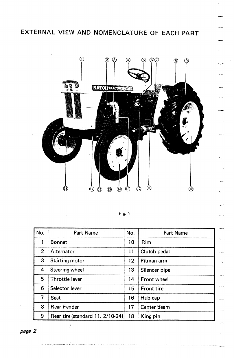
EXTERNAL
VIEW AND
NOMENCLATURE
OF EACH PART
No. Part Name
1 Bonnet
2 Alternator
3 Starting
4 Steering wheel
Throttle
5
6 Selector lever
7
Seat
8
Rear
9
Rear
page
2
Fig. 1
motor
lever
Fender
tire (standard 11. 2/1 0-24)
No.
10 Rim
11
Clutch pedal
12 Pitman arm
13 Silencer pipe
14
Front
15
Front
Hub cap
16
17
Center oeam
18 King pin
Part
wheel
tire
Name

@-----------------1)
No.
19 Louver
20 Filler
21
Air
Control lever
22
23
Flood light 28
Part Name No.
cap
cleaner
Fig. 2
24
Instrument panel
Step
25
Fuel cap
26
Steering lever
27
Head
Part Name
lamp
page 3
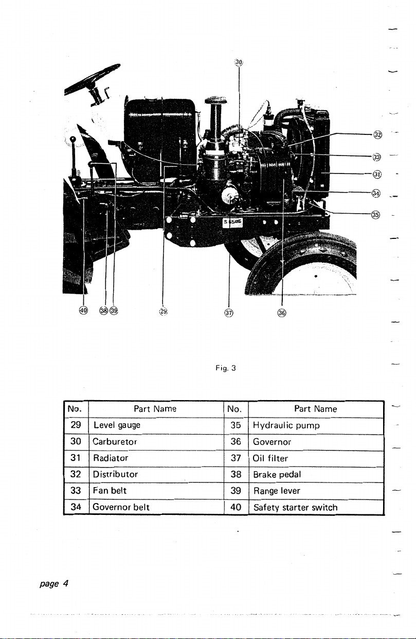
Fig. 3
No. Part Name No. Part Name
Level gauge
page
29
30
31
32
33
34
4
Carburetor
Radiator
Distributor
Fan
belt
Governor
belt
Hydraulic
35
36
Governor
37
Oil filter
38 Brake pedal
Range lever
39
40
Safety
pump
starter
switch
SECTION
1.
OPERATION
STARTING
Before starting
water, transmission
daily check specified
(
1)
The engine
not run excepting when
Accordingly, when starting the engine, place range lever
"NEUTRAL".
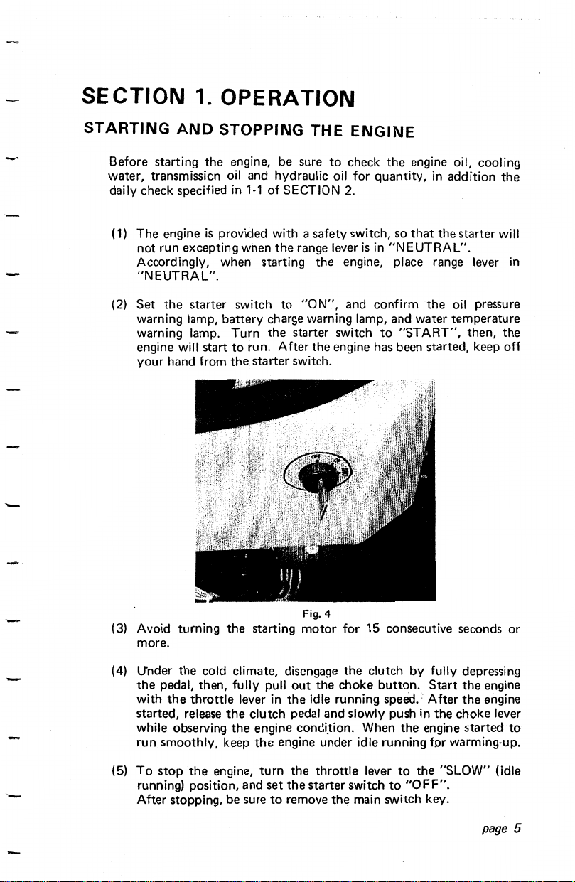
2)
Set
(
the
warning lamp, battery charge warning lamp, and water temperature
warning lamp. Turn the starter switch
engine will start
your hand from
AND
STOPPING THE
the
engine, be sure to check
oil
in
is
provided with a safety switch, so
starter switch
to
the
and hydraulic
1-1
of
SECTION
the
range lever
to
"0
N", and confirm
run. After
starter switch.
the
ENGINE
the
oil
for quantity,
2-
is
engine has been started, keep off
engine oil, cooling
in
that
in
"NEUTRAL"_
to
the starter will
the
"START",
addition
oil
pressure
then,
the
in
the
-
(3)
Avoid turning
more.
U"nder
(4)
(5)
the cold climate, disengage
the
pedal, then, fully pull
the
stop
throttle
the
with
started, release
while observing
run smoothly, keep
To
running) position, and
After stopping, be sure
Fig. 4
the
starting motor for 15 consecutive seconds or
the
clutch by fully depressing
out
lever in
the
clutch pedal and slowly push in the choke lever
the
engine condi.tion. When
the
engine,
turn
set
to
the choke button.
the
idle running speed.· After
engine under idle running for warming-up.
the throttle lever
the
starter switch
remove the main switch key.
the
engine started
to
the
to
"OFF".
Start
the
engine
the
engine
to
"SLOW" (idle
page 5
CONTROLS
In
engine, it will
Control System
through 12.
1.
OIL
When
turned on. Always
whether
started,
operation,
is
faulty.
pressure switch condition.
case
the
starter switch turns off under
be
caused
to
have a trouble of "DIESELING".
of
the engine and tractor are as shown
PRESSURE WARNING LAMP
the
starter switch
the
engine
the
lamp
the
engine oil may be insufficient or
Stop
the
is
set
to
the
lamp should be watched, because it indicates
is
properly lubricated. Normally, after
is
turned
off. If the. lamp keeps
operation, and check
"ON",
the
high speed running
the
oil pressure warning lamp
to
light
the
oil pressure switch
quantity
of
the
oil and
in
the
on
Figs. 7
of
the
is
--
engine ·
during
·-
the
oil
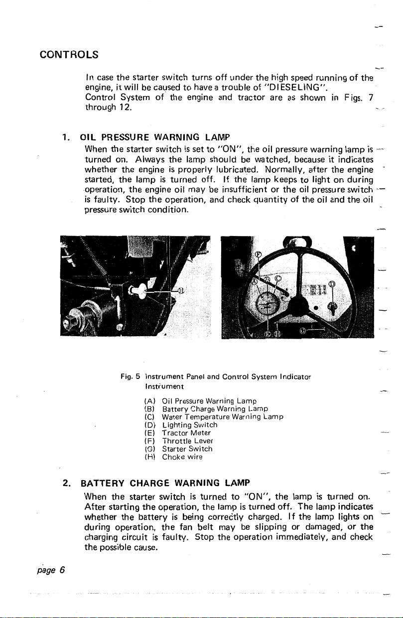
Fig. 5
Instrument
Instrument
(A)
(B)
(C)
(D)
(E)
(F)
(G)
(H)
Panel and
Oil
Pressure Warning
Battery
Charge Warning
Water
Temperature
Lighting
Tractor
Meter
Throttle
Starter
Switch
Choke
wire
2. BATTERY CHARGE WARNING LAMP
When
the
page
After starting
whether
during operation,
charging circuit
the
possible cause.
6
starter
the
switch
the
operation,
battery
the
is
faulty.
is
is
being correctly charged. If the lamp lights on
fan belt may be slipping or damaged, or the
Control
System
Indicator
Lamp
Lamp
Switch
Lever
turned
the
Stop
Warning
to
lamp
the operation immediately, and check
"ON",
is
turned
Lamp
the
lamp
is
off. The lamp indicates
turned on.
3. WATER TEMPERATURE WARNING LAMP
Dust accumulations will adversely affect the radiation efficiency of
radiator. If
(100°C)
on. Immediately
radiator for dust and water. If necessary, clean
water.
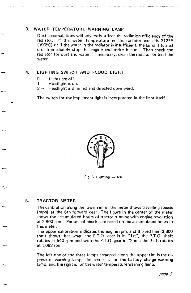
4.
LIGHTING
0 - Lights are off.
1 - Headlight
2-
Headlight
The
switch for
or
if
SWITCH
the
water
the
water in
is
on.
is
dimmed and directed downward.
the
temperature
the
stop
AND
implement light
radiator
the
engine and make it cool.
FLOOD
in
is
insufficient,
LIGHT
is
incorporated
the
radiator exceeds 212°F
the
radiator
in
the
lamp
Then
the
light itself.
is
check
or
feed
the
turned
the
the
-
Fig. 6
5.
TRACTOR METER
The
calibration along
(mph)
at
the
the
shows
at 2,800 rpm. Periodical checks are based
this meter.
The upper calibration indicates
rpm) shows
rotates
at 1 ,092
The
pressure warning lamp,
lamp, and
accumulated hours of
that
at
540
rpm. ·
left
one
of
the
6th
forward gear.
when.
rpm
and
the
three
right
is
the
lower rim of
the
with
lamps arranged along
the
for
the
Lighting
the
The
figure in
tractor
the
engine rpm, and
P.T.O. gear
the
P.T.O. gear
center
is
water
temperature
Switch
meter shows travelling speeds
the
center of
running with engine revolution
on
the
accumulated hours
the
"1st",
"2nd",
the
upper
battery charge warning
warning lamp.
for
is
in
in
the
the
meter
red line (2,800
the
P.T.O. shaft
the
shaft rotates
rim
is
the oil
page
in
7
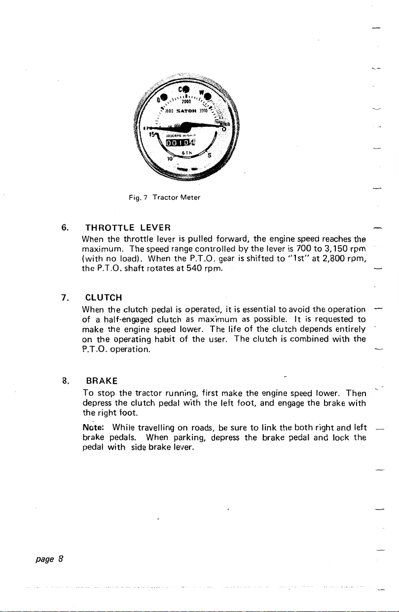
Fig. 7
Tractor
Meter
6.
THROTTLE LEVER
When
the
maximum.
throttle
(with no load). When
the
P.T.O.
shaft
lever
is
The
speed range controlled
rotates
pulled forward,
the
P.T.O. gear
at
540
rpm.
by
is
shifted
the
7. CLUTCH
When
the
clutch pedal
of a half-engaged clutch as maximum as possible. It
make
the
engine speed lower.
the
on
operating habit
P.T.O. operation.
8. BRAKE
To
stop
the
tractor
depress
the
Note: While travelling
the
clutch pedal with
right foot.
brake pedals. When parking, depress
pedal with side brake lever.
is
operated, it
of
the
The
user.
is
life
The
running, first make
the
left foot, and engage
on
roads, be sure
essential
of
the
to
the
the
engine speed reaches
lever
is
700
to
to
the
clutch depends entirely
clutch
is
to
"1st"
at
avoid
the
is
requested to
combined with
engine speed lower.
the
link
the
brake pedal
both right and left
and
the
3,150
rpm
2,800 rpm,
operation
the
Then
brake with
lock
the
page 8
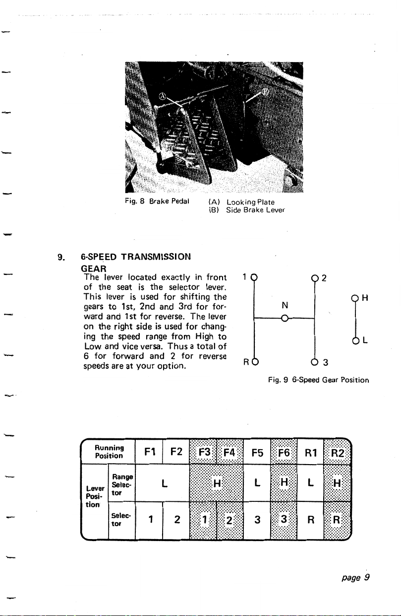
Fig. 8 Brake Pedal
9. 6·SPEED TRANSMISSION
GEAR
The lever located exactly
the
seat
is
the
of
This lever
gears
ward and 1st for reverse. The lever
on
the
ing
Low and vice versa. Thus a total
6 for forward and 2 for reverse
speeds are at your option.
is
to
1st, 2nd and 3rd for for-
right side
the
speed range from High
selector lever.
used for shifting
is
used for chang-
in
(A)
Looking
Side Brake Lever
(8)
front
the
to
of
Plate
N
R
Fig. 9 6-Speed Gear Position
2
[
3
Running
Position
Lever
Posi-
tion
Range
Selec-
tor
Selec-
tor
F1
1
page
9

10.
SEAT
The
operator's
both
for
most suitable posture.
11.
DIFFERENTIAL
The
differential lock
.speed so
front
Fig.
that
seat
can be adjusted
and
rear directions so
10
Seat
LOCK
is
either
of
in
a device for making
the
left or right wheel will
the
range of 1.77 in.
that
the
operator
the
rear wheels
not
slip.
(45
can have
at
the
mm)
the
same
page
Fig.
11
Differential
How
to
engage
the
differential lock:
To
engage
the
slip
or
slow
differential lock,
down
the
heel. Faulty engagement
Lock
stop
tractor
speed, then, depress
at
one
time
the
tractor
depressing
operation repeatedly with harder depressing. If either
right wheel has already begun slipping;
running or disengage
pedal. Make sure
is
depressed,
10
the
that
lock
the
the
is
in effect.
clutch, then, depress
pedal
turn
is
fully depressed. As far
running before
the
is
the
throttle
the
pedal by
requested
of
lever
the
to
the
the
the
differential lock
as
the
start
to
right
same
left or
idle
pedal
 Loading...