

Any
Prior
improper
to
the
handling
operation
Manual carefully and have a
In
particu lar,
the
strictly followed.
{;{
When
{;{
{;{
{;{
{;{
{;{
{;{
{;{
{;{
{;{
{;{
{;{
{;{
{;{
{;{
{;{
{;{
{;{
running
bra
ke
pedals
Make
sure
shaft.
Always
jackets,
danger
When
leaving
pull
out
Never
make a sharp
When
descending a slope
the
brake.
Never
operate
When
making a sharp
Never
operate
clutch,
Be
careful
Do
not
implement.
When
towing,
When
refuelling,
not
catch
Use a
safe
the
fuel
Never
touch
had
sufficient
Always
Never
operate
can
collect.
Do
not
proper
When
mounting
given
in
the
are
that a guard
wear
relatively
shirts
sleeves
of
catching
the
the
starter
the
the
brake,
throttle
particularly
carry
set
fire.
fuel
container.
cap
securely.
engine
time
keep
positive
the
allow
children
instructions.
"Safety
tractor
interlocked
them
tractor,
key.
turn
differential
tractor
any
the
be
to
tractor
an
Precautions"
of
of
instructions
at
so
is
in
place
tight
and
or
other
in
moving
be
sure
at
high
in
reverse,
turn,
comfirm
on a slope
lever
and
when
running
persons
hitch
point
sure
to
stop
Fill
parts
after
cool.
battery
post
engine
to
operate
implement
the
tractor
the
tractor,
thorough
given
high
speed
that
they
when
belted
loose
parts,
to
stop
speed.
be
lock
when
that
that
steering
on a slippery
on
the
below
the
engine.
the
tank
operating
covered
in a
closed
the
on
the
in
theimplement
could lead
understanding
in
or
on
wi
II
not
operating
clothing
clothing
engine
the
sure
not
running
the
differential
seems
wheel
tractor,
the
center
Also
outdoors
the
with
building
tractor,
tractor,
be sure
"Safety
roads,
be
operated
the
when
should
or
implement.
engine,
to
abruptly
on a public
to
be
abruptly
road.
nor
line
take
and
tractor
rubber
where
nor
be
sure
Operation
to
an ,accident.
to
read this
Precautions"
make
belt
pulley
operating
not
be
apply
lock
dangerous.
on a slope
on
the
of
the
special
wipe
up
or
the
engine
boot
on
carbon
adults
to
follow
Manual.
Instruction
of
the
description.
sure
the
right
independently.
or
P.T.O.
the
tractor.
worn
because
the
parking
operate
the
road.
is
disengaged.
Do
not
as it
is
linkage
drawbars
rear
axle.
care
so
that
spilled
fuel.
until
the
end
of
monoxide
to
operate
the
instructions
must
and
driven
Loose
of
brake
clutch
operate
dangerous.
fuel
Replace
parts
have
the
cable.
fumes
it
without
be
left
the
and
or
the
and
will
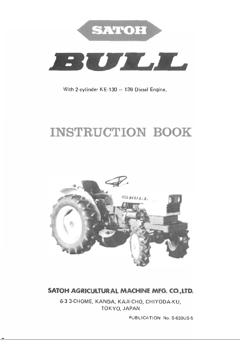
With 2-cylinder KE-130 -
138
Diesel Engine.
6-3 3-CHOME,
KANDA,
TOKYO,
KAJI-CHO,
JAPAN
PUBLICATION
CHIYODA-KU,
No. S-630US-5

-
Equipped with a 2-cylinder, 25
S-6300
with big capacity, high quality performance and outstanding durability
providing increased economy.
Making
SATOH engineers, the S-630 and
their components which consist
The careful assembling work coupled with quite severe performance
strict quality control makes assurance
for
tractors are, respectively, 2-wheel and 4-wheel drive
the
best use
the
S-630 and S-6300.
of
long experiences and the latest technology
HP
diesel engine,
S-6300
of
unsurpassed and precision machined parts.
are built sturdy and rugged
of
high quality and
the
SATOH S-630 and
type
farm tractors
top
performance
test
of
in
the
all
and
This instruction manual contains information on
of
and maintenance
prehensive and essential, and
utilizing your tractor.
How well your SATOH
depends greatly upon
requested
the operation and maintenance services will properly be carried
to keep the
Should any information
dealer or distributor stating
tractor
We
that
tractor
concerned.
are sure you will be happy with SATOH tractor.
your SATOH
tractor
the
this manual be read carefully and kept ready for use so
in
top
mechanical condition at
as
tractor.
is
designed
continues
manner
to
your
the
machine and engine serial numbers
The information contained
to
in
which
tractor
be required, consult
the
operation, lubrication
assist you,
to
give
it
is
if
unexperienced,
satisfactory performance
operated. It is, therefore,
all
times.
out
your
is
com-
that
in
order
SATOH
of
the
in
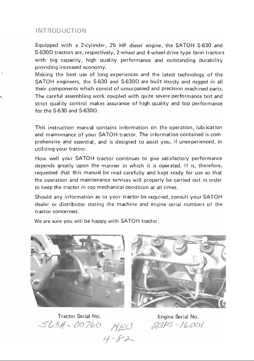
Tractor Serial No.
Engine Serial No.
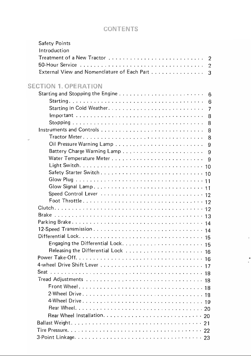
Safety Points
Introduction
Treatment
50-Hour Service
External View and Nomenclature
Starting and Stopping
Instruments and
Clutch. , . ,
Brake
Parking Brake
12-Speed Transmission
Differential Lock, ,
Power Take-Off
4-wheel Drive Shift Lever
Seat
Tread Adjustments . . . . . . . . . . . . . . . . . . . . . . . . . . . . . . . . . 18
Ballast Weight
Tire Pressure
3-Point Linkage
of a New
Starting. . . . . . . . . . . . . . . . . . . . . . . . . . . . . . . . . . . .
Starting
Important . . . . . . . . . . . . . . . . . . . . . . . . . . . . . . . . . .
Stopping.
Tractor Meter
Oil
Battery Charge Warning
Water Temperature
Light Switch
Safety Starter Switch
Glow Plug
Glow Signal Lamp
Speed Control Lever
Foot
Engaging the Differential Lock
Releasing the Differential Lock
........
Front
2-Wheel Drive
4-Wheel Drive
Rear Wheel.
Rear Wheel Installation
in
Pressure Warning Lamp
Th
rattle,
..
..
, , , ,
Wheel
......................................
Tractor
.................................
Cold Weather
. . . . . . . . . . . . . . . . . . . . . . . . . . . . . . . . . .
Controls.
..................
...................................
....................................
, . , ,
, . , , . ,
... , ..
.... , ..
.. , .. , ..
....
, . . . . . . . . . . . . . . . . . . . . . . . . . . . . . . . 16
'
.................................
...................................
..................................
..................................
...................................
.....................................
....................................
.............
of
Each
the
Engine. . . . . . . . . . . . . . . . . . . . . .
.........................
. . . . . . . . . . . . . . . . . . . . . . . . . .
...................
Lamp.
Meter.
.............................
...............................
....................
..
, , . ,
.... , ...
, . ,
......
, ,
..
.....
.............................
............................
. . . . . . . . . . . . . . . . . . . .
. . . . . . . . . . . . . . . . . . . . . . .
.... , ..
, . , , ,
,
....
, , ,
..
, . , , . ,
, ,
.. , ....
, , . " ,
.. , .. , ... , ....
..
, ,
...
..
, ,
, . . . . . . . . . . .
Part.
. . . . . . . . . . . .
,
..............
, , . , , , ,
... , .....
, , ,
... , ......
.... , ..
, , . , , ,
.. , ...........
, . ,
.... , ..
... , ...
, . . . . . . . .
.... , ....
, , , , . , , .
, . , , , , , . 14
'.
. . .
, . , ,
, . , . , , 15
..
" 2
..
..
..
" 7
..
..
..
, 8
..
..
..
, , . 13
, , . , 14
..
,
...
'"
2
3
6
6
8
8
8
9
9
9
10
10
11
11
12
12
'12
15
16
17
18
18
18
19
20
20
21
22
23
...
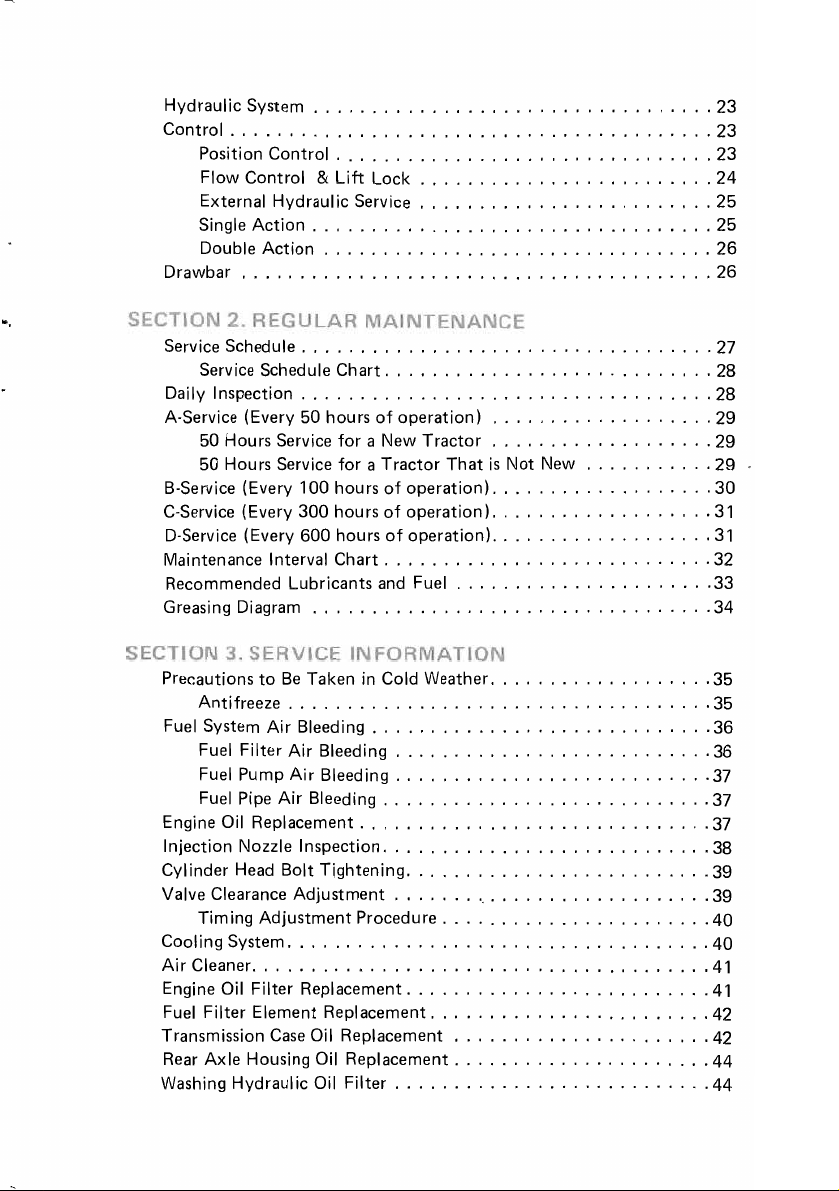
Hydraulic System
Control
Drawbar
Service Schedule
Daily Inspection
A-Service (Every 50 hours
B-Service (Every 100 hours
C-Service (Every 300 hou
D-Service (Every 600 hours
Maintenance Interval Chart
Recommended Lubricants
Greasing Diagram
.........................................
Position Control
Flow Control &
External Hydraulic Service
Single
Action
Double
........................................
Service Schedule Chart
50 Hours Service
50 Hours Service
..................................
................................
Lift
..................................
Action
.................................
...................................
...................................
for
for a Tractor
..................................
Lock
.........................
.........................
............................
of
operation)
a New
Tractor
of
operation)
rs
of
operation).
of
operation).
............................
and
Fuel
...................
...................
That
is
...................
......................
Not
New
...........
..................
..................
23
23
23
24
25
25
26
26
27
28
28
29
29
29
30
31
31
32
33
34
Precautions
Antifreeze
Fuel System
Fuel Filter
Fuel Pump
Fuel Pipe
Engine Oil Replacement
Injection Nozzle Inspection
CYlinder
Valve Clearance
Timing
Cooling System
Air
Cleaner
Engine Oil Filter Replacement
Fuel
Transmission
Rear
Washing Hydraulic Oil
to
Be
Taken in Cold Weather
....................................
Air
Bleeding
Air
Air
Air
Bleeding
Head
Bolt
Adjustment
Adjustment
....................................
.........
Filter
Element Replacement.
Case
Axle Housing Oil Replacement
.............................
Bleeding
Bleeding
............................
..............................
............................
Tightening
Procedure
,
........................
Oil Replacement
Filter
...................
...........................
...........................
..........................
.......
..........................
...........................
'
....................
.......................
.......................
......................
......................
'
.....
35
35
36
36
37
37
37
38
39
39
40
40
41
41
42
42
44
44
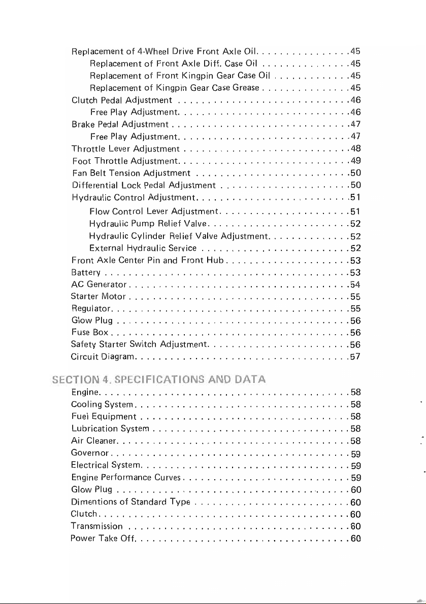
Replacement
Replacement
Replacement
Replacement
Clutch Pedal Adjustment
Free Play Adjustment
Brake Pedal Adjustment
Free Play Adjustment
Throttle Lever Adjustment
Foot Throttle Adjustment
Fan Belt Tension Adjustment
Differential Lock Pedal Adjustment
Hydraulic Control Adjustment
Flow Control Lever Adjustment.
Hydraulic Pump Relief Valve
Hydraulic Cylinder Relief Valve Adjustment
External Hydraulic Service
Front Axle Center
Battery
AC
Generator
Starter Motor
Regulator
Glow Plug
Box
Fuse
Safety Starter Switch Adjustment
Circuit Diagram
of
4-Wheel Drive Front Axle Oil.
of
Front Axle Diff. Case
of
Front Kingpin Gear Case
of
Kingpin Gear Case Grease
.............................
.............................
..............................
.............................
............................
.............................
..........................
..........................
........................
.........................
Pin
and
Front
Hub
.........................................
.....................................
.....................................
........................................
.......................................
........................................
........................
....................................
......................
...............
Oil
...............
Oil
.............
...............
.....................
..............
.....................
45
45
45
45
46
46
47
47
48
49
50
50
51
51
52
52
52
53
53
54
55
55
56
56
56
57
..........................................
Engine
Cool ing System
Fuel Equipment
Lubrication System
Air Cleaner
Governor
Electrical System
Engine Performance Curves
Glow Plug
Dimentions of Standard Type
Clutch
..........................................
Transmission
Power Take Off
....................................
...................................
.................................
.......................................
........................................
...................................
............................
........................................
.....................................
....................................
..........................
58
58
58
58
58
59
59
59
60
60
60
60
60

Brakes
..........................................
Steering
Tread Adjustment
Hydraulic Power Lift
3-Point Linkage
Wheel Equipment
Travel Speed
Capacities (Approximate initial fill)
.........................................
..................................
................................
....................................
..................................
......................................
......................
61
61
61
61
61
61
62
62
All
components of SATOH tractors model S-630 &
to
stringent checking during assembly
tractor
first
heavy
would normally use, and run the engine at lower speed.
should be carefully checked over by
25'"
50
hours operation, heavy
duty
work
is
unavoidable, drive
in
the
factory. However, a new
the
operator himself. For
duty
work should be avoided.
in
a gear one stage lower than you
S-6300
are subject
the
If
After the first 50 hours running,
checking should be carried
(1) Replace the oil filter and engine oil.
(2)
Replace the transmission oil and clean
all
(3) Retighten
(4)
Check and adjust
(5) Check
correct.
(6) Retighten
This 50-hour Service
top
condition, so it must be
bolts and nuts.
the
fan belt tension.
the
wheels
to
see if
the
cylinder head bolts and adjust valve clearances.
is
an
the
following service, maintenance and
out.
their
condition
essential procedure for keeping
done
properly.
the
hydraulic oil filter.
is
good and tire pressure
the
tractor
is
in
-2-
6 5
4
3
2
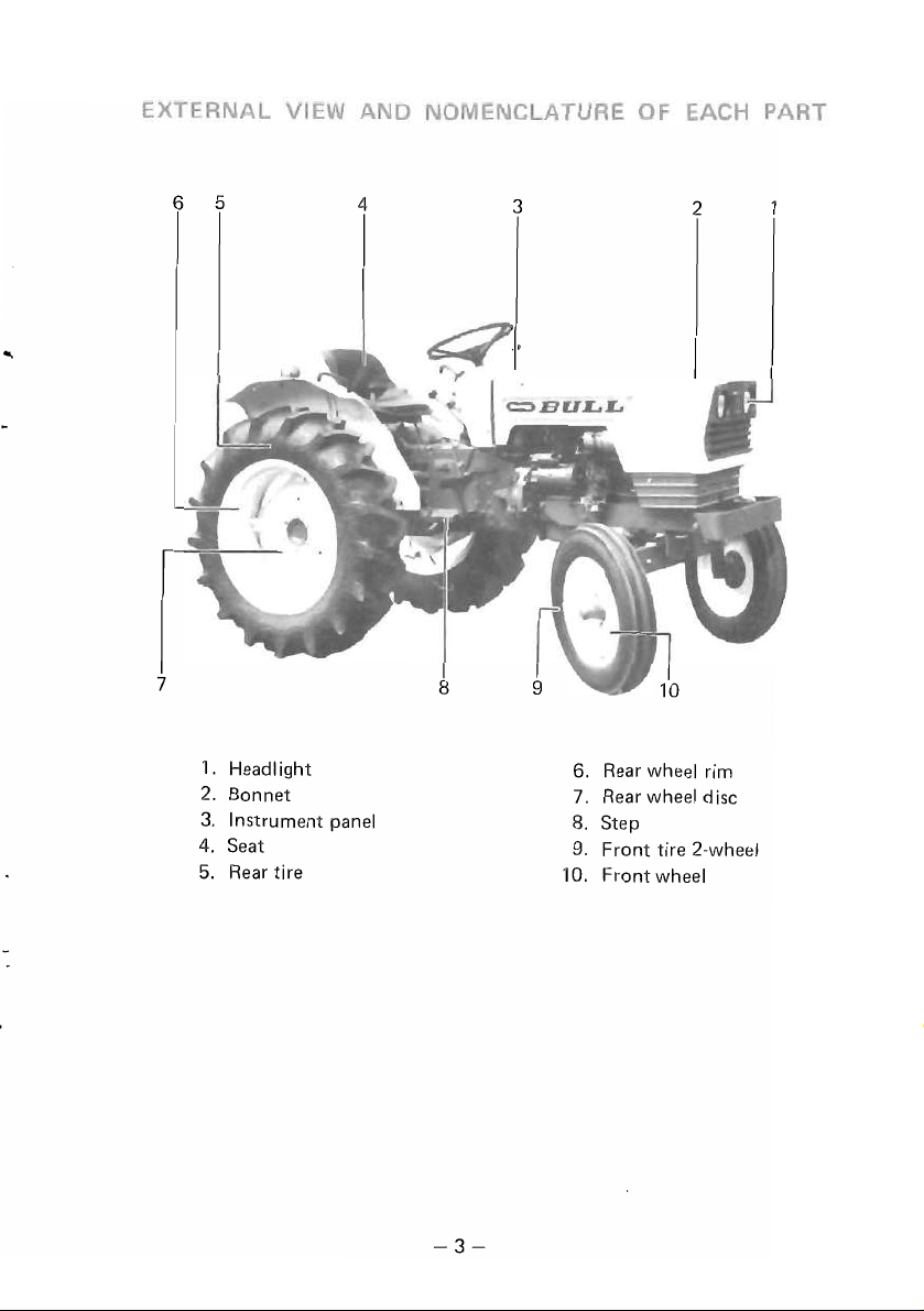
1.
Headlight 6.
Bonnet 7.
2.
3. Instrument panel
4. Seat
5. Rear tire
-3-
Rear wheel rim
Rear wheel disc
Step
8.
9. Front tire 2-wheel
Front wheel
10.
12
11
3
J
4
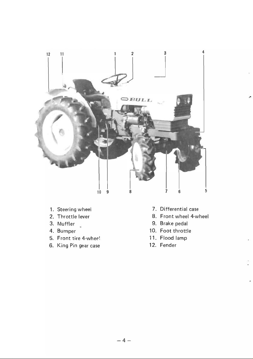
1.
Steering wheel
Throttle lever
2.
3. Muffler
Bumper
4.
Front tire 4-whee!
5.
King
Pin
6.
gear case
10
9
8 6
7.
Differential case
8.
Front wheel 4-wheel
9. Brake pedal
10.
Foot
throttle
11.
Flood lamp
12.
Fender
5
-4-
10
11
2
3 4
6
------5
-'------7
9 8
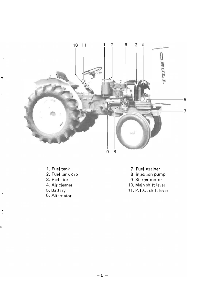
1. Fuel tank 7. Fuel strainer
2. Fuel tank cap 8. Injection pump
3. Radiator
4. Air cleaner 10. Main shift lever
5. Battery
6. Alternator
9. Starter
11. P.T.O. shift lever
motor
-5-
Before starting the engine, be sure
1.
Confirm
2. Check
that
the
the
amount
fuel tank
of
oil
to
check the following points.
is
filled with sufficient fuel.
in
the
engine, and transmission and check
cooling water.
in
3. Always perform the daily maintenance described
On
the S-630 and S-6300, the safety starter switch
venting unforeseen accidents from breaking
out
of SECTION 2.
is
provided for pre-
in
starting the engine.
Installed between the starter switch and starter motor, the safety starter
switch works
is
not
motor
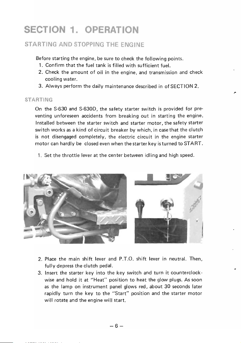
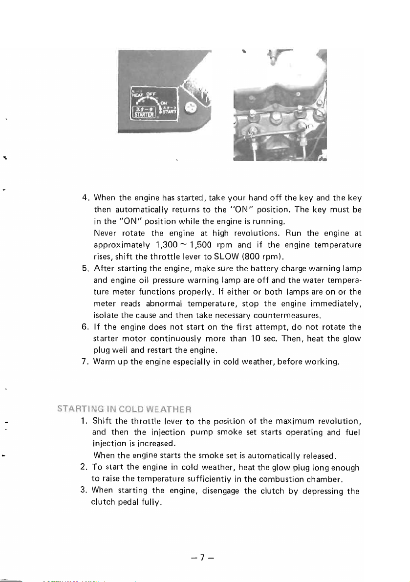
1.
Set
as
a kind of circuit breaker by which,
disengaged completely,
the
electric circuit
can hardly be closed even when the starter key
the
throttle
lever at
the
center between idling and high speed.
in
case
that
the clutch
in
the engine starter
is
turned to START.
2. Place the main shift lever and P.T.G. shift lever
fully depress
3. Insert the starter key into
wise and hold it at
as
the lamp on instrument panel glows red, about
rapidly turn
will
rotat~
and
the
the
the
clutch pedal.
the
"Heat"
key
to
position
the
"Start"
engine will start.
key switch and turn it counterclock-
to
heat the glow plugs.
position and
-6-
in
neutral. Then,
30
seconds later
the
starter
As
soon
motor
4. When
5. After starting the engine, make sure the battery charge warning lamp
6.
7.
1.
2. To start
3. When starting
the
engine has started, take your hand off the key and
to
the
"ON"
then automatically returns
in
the
"ON"
position while the engine
Never rotate the engine at high revolutions. Run the engine at
approximately 1
rises, shift
and engine oil pressure warning lamp are
ture meter functions properly.
meter reads abnormal temperature, stop
isolate
the
If
the
engine does
starter
Warm
Shift
and then the injection pump smoke set starts operating and fuel
injection
to
clutch pedal fully.
plug
When
raise
motor
well
up
the
is
the
the
the
and restart
the
throttle
,300'"
the
throttle
cause and then take necessary countermeasures.
continuously more than 1 0 sec. Then, heat the glow
engine especially
increased.
engine starts the smoke set
engine
temperature sufficiently
the
1 ,500 rpm and if the engine temperature
lever
to
SLOW
If
either or both lamps are on or the
not
start on the first attempt,
the
engine.
in
cold weather, before working.
lever
to
the
position of the maximum revolution,
in
cold weather, heat
engine, disengage the clutch by depressing the
position. The key must be
is
running.
(800 rpm).
off
and the water tempera-
the
engine immediately,
do
is
automatically released.
the
glow plug long enough
in
the combustion chamber.
the
not rotate
key
the
-7-
NOTES:----------------------------------------
1)
After
the
engine has started, comfirm
that
the
engine
smoothly listening carefully to ascertain if nothing abnormal
sounds, and inspect for oil and water leakage.
2)
In
case fuel runs
filling
the
even stopped soon
fuel
out,
tank;
be sure
otherwise
after
to
bleed
the
fuel system after
the
engine may
not
be started (or
started). (See SECTION 3. BLEEDING
THE FUEL SYSTEM)
is
running
re-
Never use
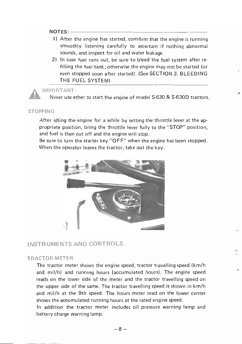
After idling
ether
to
the
engine for a while by setting
propriate position, bring
is
then
cut
rn
the
off and
starter
leaves
and fuel
Be
sure
When
to
the
tu
operator
start
the
the
the
engine of model S-630 & S-630D tractors.
the
the
key
tractor,
throttle
engine
"0
F F" when
lever fully
wi
II
stop.
the
take
out
throttle
to
engine has been
the
key.
the
lever at
"STOP"
the
ap-
position,
stopped.
,"
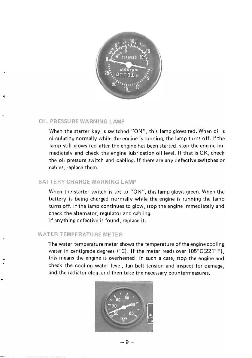
The
tractor
meter shows
the
engine speed,
tractor
travelling speed
(km/h
and mil/h) and running hours (accumulated hours). The engine speed
the
reads on
lower side
the upper side of the same. The
and mil/h
shows
In
addition the
battery
at
the
the
accumulated running hours
charge warning lamp.
of
the
meter and
tractor
9th
speed. The hours meter read on
tractor
meter includes oil pressure warning lamp and
the
travelling speed
at
the
tractor
travelling speed
is
shown
the
lower
rated engine speed.
in
km/h
center
on
-8-
When
the
starter key
is
switched
"ON",
circulating normally while the engine
lamp still glows red after
mediately and check
oil
the
pressure switch and cabling.
the
engine has been started, stop
the
engine lubrication oil level.
cables, replace them.
the
When
battery
turns off.
check
If
anything defective
starter switch
is
being charged normally while the engine
If
the lamp continues to glow, stop the engine immediately and
the
alternator, regulator and cabl
is
set
to
"ON",
is
found, replace it.
this lamp glows red. When
is
running,
If
there are any defective switches
the
lamp turns off.
If
that
the
engine
is
OK, check
this lamp glows green. When
is
running the lamp
ing.
oil
If
is
the
im-
or
the
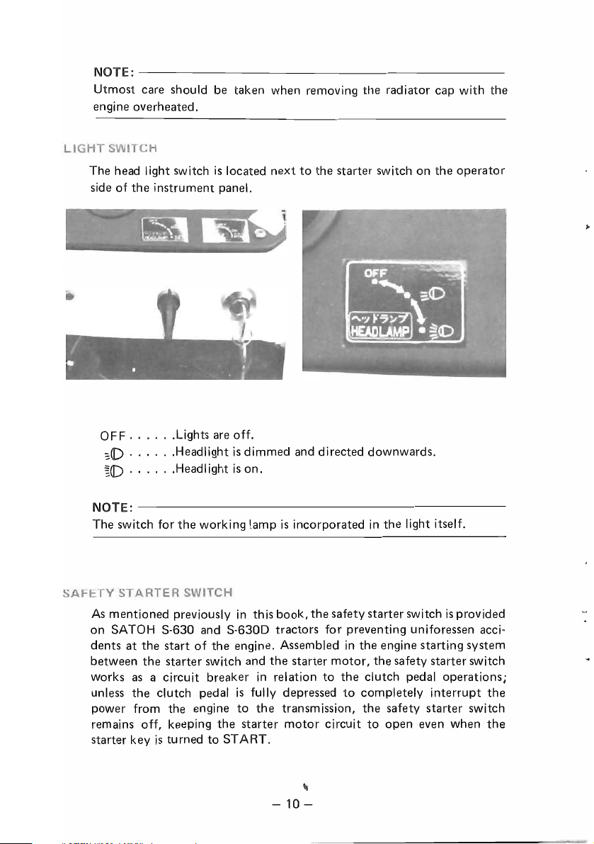
The water temperature meter shows the temperature
water
in
centigrade degrees
this means the engine
(OC).
is
overheated;
If
the
meter reads over 105°C(221° F),
in
such a case, stop
ofthe
engine cooling
the
engine and
check the cooling water level, fan belt tension and inspect for damage,
and the radiator clog, and then take the necessary countermeasures.
-9-
NOTE:--------------------------------------------
Utmost care should be taken when removing the radiator cap with
engine overheated.
is
The head I ight switch
side of the instrument panel.
OF F
......
~(J)
......
~(J)
......
Lights are off.
Headlight
Headlight
located next
is
is
dimmed and directed downwards.
on.
to
the starter switch on the
operator
the
NOTE:---------------------------------------------
The switch for
As
mentioned previously
on SATOH S-630 and S-630D tractors for preventing uniforessen acci-
dents
at
between the starter switch and
as
works
unless the clutch pedal
power from the engine to
remains off, keeping the starter
starter key
the
working lamp
the start
a circuit breaker
of
the engine. Assembled
is
turned to START.
is
incorporated
in
this book, the safety starter switch
the
starter motor, the safety starter switch
in
relation
is
fully depressed
the
to
transmission, the safety starter switch
motor
circuit to open even when
in
the
in
the engine starting system
the clutch pedal operations;
to
completely interrupt
light itself.
is
provided
the
the
."
-
10-
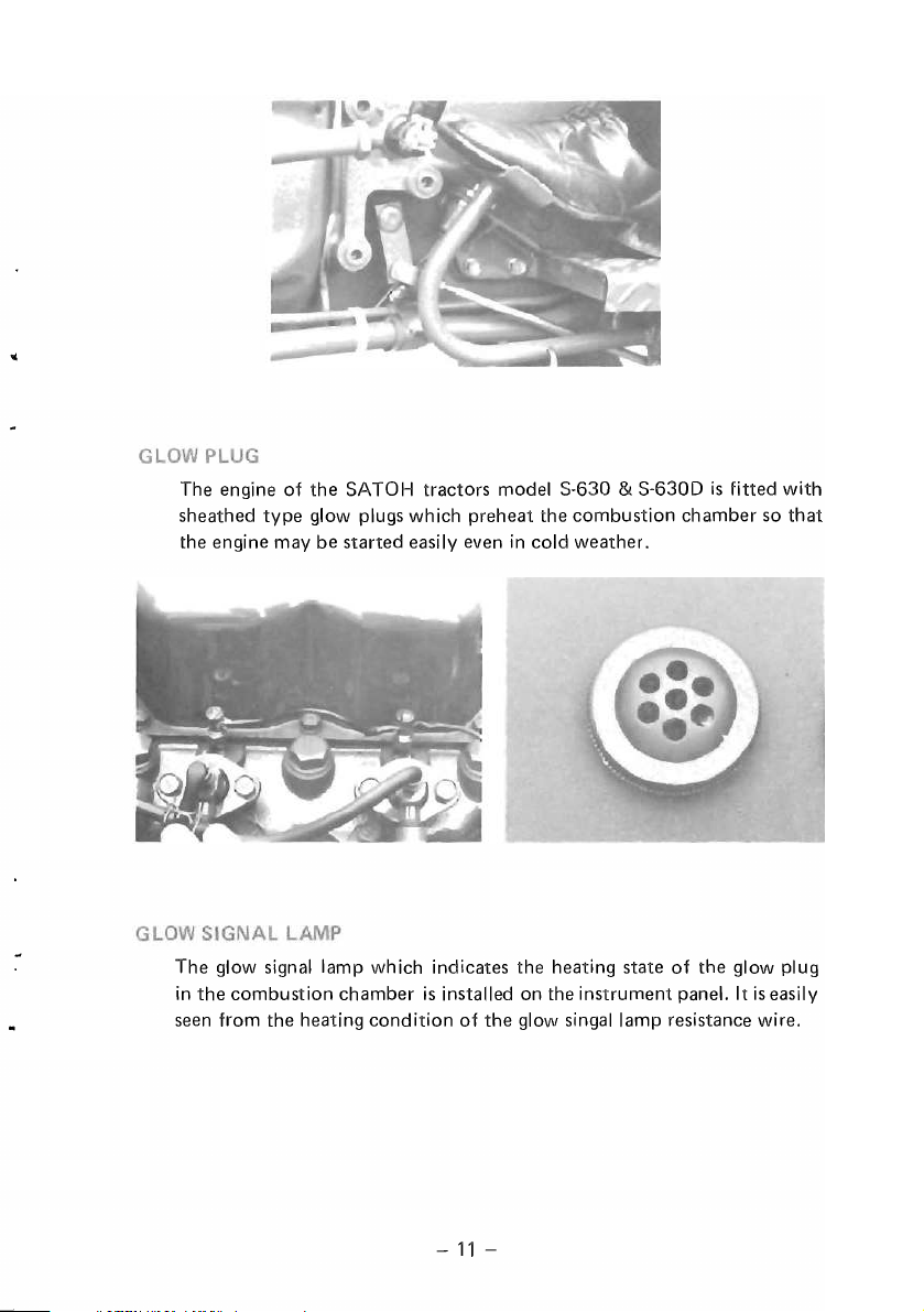
The
engine
sheathed
the
engine
The
glow signal
in
the
combustion
seen
from
of
type
may
the
heating
the
SATOH
glow plugs
be
started
lamp
which
chamber
condition
tractors
which
easily even in
indicates
is
model
preheat
installed
of
the
S-630 & S-6300
the
combustion
cold
weather.
the
heating
on
the
instrument
glow
singallamp
state
is
fitted
chamber
of
the
glow
panel.
It
resistance
so
is
easily
wire.
with
that
plug
-
11
-
When the speed control lever
engine speed reaches the maximum of 2,750 rpm.
of
The rated speed
engine speed
life from
therefore, to run the engine
your
the Engine Model KE-130-138
is
not only the most appropriate one to get the longest service
tractor
but
is
pulled fully toward the operator, the
also the most economical one. It
at
the rate
of
2,500 rpm.
is
2,500 rpm. This
is
the best
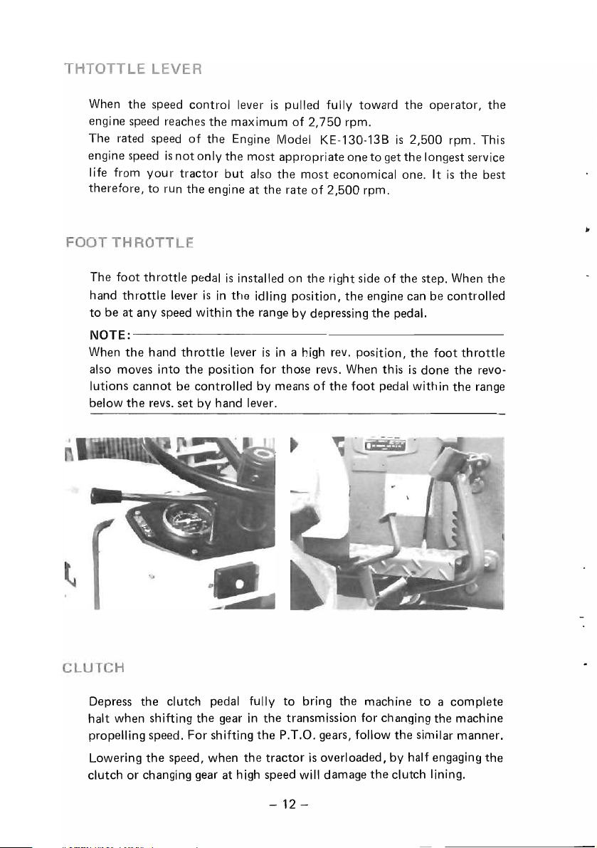
The foot
hand
to be at any speed within
throttle
throttle
lever
pedal
is
is
installed on the right side
in
the
idling position,
the
range by depressing the pedal.
of
the
engine can be controlled
NOTE:---------------------------------------------
When
the
hand
throttle
also moves into
lutions cannot be controlled by means
below
the
the
revs. set by hand lever.
lever
is
in
a high rev. position,
position for those revs. When this
of
the
foot
pedal within
the step. When
the
foot
throttle
is
done the revo-
the
the
range
to
Depress the clutch pedal fully
the
gear
halt when shifting
propelling speed. For shifting
Lowering
clutch or changing gear at high speed will damage
the
speed, when
in
the
the
bring the machine
the
transmission for changing the machine
P.T.O. gears, follow
tractor
is
overloaded, by half engaging
-
12-
the
the
clutch lining.
to
a complete
similar manner.
the
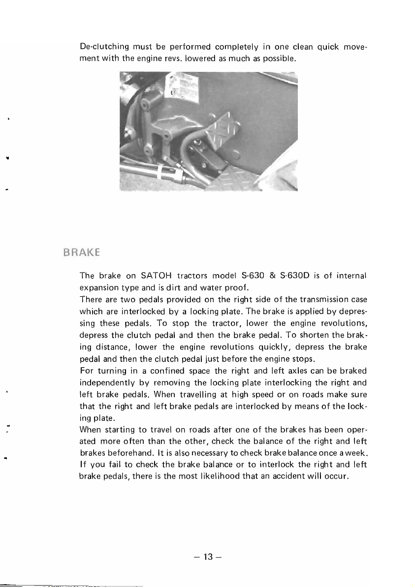
De-clutching must be performed completely
ment with
the
engine revs. lowered
as
much
in
one clean quick move-
as
possible.
The brake on SATOH tractors model S-630
type
and
is
expansion
There are
two
dirt and water proof.
pedals provided on
the
right side
which are interlocked by a locking plate. The brake
the
sing these pedals. To stop
tractor,
depress the clutch pedal and then the brake pedal. To shorten
ing
distance, lower the engine revolutions quickly, depress
pedal and then
For turning
independently by removing
the
clutch pedal just before
in
a confined space the right and left axles can be braked
the
locking plate interlocking the right and
& S-630D
lower
the
engine stops.
is
of internal
of
the transmission case
is
applied by depres-
the
engine revolutions,
the
the
brak-
brake
left brake pedals. When travelling at high speed or on roads make sure
that
the right and left brake pedals are interlocked by means
ing
plate.
When starting
ated more often than the
brakes beforehand. It
If
you
brake pedals, there
fail
to
travel on roads after one
other,
is
also necessary to check brake balance once a week.
to
check
the
brake balance or
is
the most likelihood
of
the
check the bal ance of the right and left
to
interlock the right and left
that
an accident will occur.
brakes has been oper-
of
the
lock-
-13-
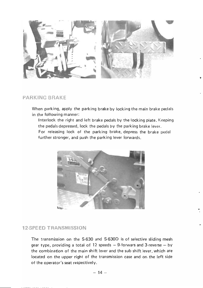
When parking, apply
in
the
following manner:
I nterlock
the
the
right and left brake pedals by
pedals depressed, lock
For releasing lock
further stronger, and push
the
parking brake by locking
the
pedals by the park
of
the
parking brake, depress the brake pedal
the
parking lever forwards.
the
main brake pedals
the
locking plate. Keeping
ing
brake lever.
The transmission on
gear
type,
providing a total
the
combination
located on
of
the
operator's seat respectively.
of
the
upper right
the
S-630 and
of
12 speeds - 9-forwars and 3-reverse - by
the
main shift lever and
of
the
-
14-
S-6300
is
of
selective sliding mesh
the
sub shift lever, which are
transmission case and on the left side

NOTE:---------------------------------------------
When you change
clutch pedal
tractor,
shift
to
the
the
gear shift, lower the engine speed and depress
disengage
gears.
the
transmission clutch. After stopping
the
the
This device links
them at the same speed
increase traction force.
the
Before
your
right foot and engage
does not engage at
If
it still does
the
running clutch, repeat
tractor
not
the
right and left wheels
slips and
the
engage, lower the engine speed and after disengaging
in
the
transmission and rotates
to
prevent either wheel from slipping and
the
speed
is
lowered, depress
the
differential lock.
first
attempt,
the
whole operation described above.
repeat
If
the
the
operation more forcibly.
-15-
to
the
pedal with
differential lock

The differential lock
when you
put
conditions, there may be occasions when the lock does
When this occurs, depress
quickly until the lock
is
automatically released by the force
your right
is
foot
off
the pedal. However, under particular
not
release.
the
right and left brake pedals alternately and
released.
If
this happens during plowing, depress
of
the
spring
the pedal on the unplowed side and the lock will be released .
.
When
the right and left brakes are interlocked,
turning the steering wheel sharply
differential lock
is
not released by any
to
the left and
of
these means, reverse
the
lock
the
right. When
is
released by
the
tractor
a short distance.
NOTE:--------------------------------------------
Refrain from using
a road.
By
operating
mission case, the four P.T.O. speeds - 555 rpm, 774 rpm, 1 rpm,
1,320 rpm - can be selected.
When shifting the P.T.O. shift lever, depress the clutch pedal fully
to interrupt the power from the engine and make sure
brought
to
a complete halt.
the
differential lock when running at high speed or on
the
P.
T.O. shift lever located on
the
upper left
of
the
the trans-
machine
the
is
-16-
First
.. , ...
Second
Third,
Fourth
Standard
.....
....
....
p.T.a,
540
1,000
555
rpm/2,500
774
rpm/2,500
1,025
rpm/2,500
1,320
rpm/2,500
speed:
rpm/2,432
rpm/2,439
engine rpm
engine rpm
engine rpm
engine rpm
engine
rpm
engine rpm
(first)
(third)

NOTES:-------------------------------------------
1) When
2) When
3)
4)
5) Avoid using a
6)
any
so
that
the
the
the
slide
loaded.
To
reduce
possible, it
any
load.
Lubricate
Special
shaft
is
care
well
implement
universal
tractor
clutch
on
the
thrust
is
advisable
the
P.T.D.
square-shaped
should
balanced.
is
joint
is
working
the
driven
be
towed
by
does
not
with
implement
load
to
to
test
operation
shaft
drive
given
to
the
weJI.
shaft
the
the
tractor,
form
an
impact
side so
P.T.D.
as
yoke
an angle
load,
that
the
driven
with
an
much
position
care
as
should
more
than
correctly
P.T.D.
is
shaft
as
implement
possible.
so
that
be
15°.
not
much
without
the
driven
taken
adjust
over-
as
The
4-wheel
case
and
machine
it
and
Correct
drive
should
P.T.D.
shift
be
speed
lever
is
operated
shift
located
in
levers.
the
on
the
similar
Incorrect
left
of
manner
the
transmission
1O
that
for
the
-
17-

A
deluxe
S-630D
it
to
. It
the
operator's
foam
is
2-WHEEL DRIVE
Front
tread
57.9
In.
(1,470m/m)
Make
adjustment
1.
Apply
jack
2.
Loosen
the
rubber
adjustable
stature.
is
adjustable
as
under
tie-rod
operator's
in 3
to
follows
the
center
clamp
stages
in
five
meet
according
bolt
seat
at
stages
the
requirement
beam
and
is
intervals
between
to
the
and
jack
take
out
provided
of
42.1
of
type
of
up
the
the
on
1.10"
in.
each
works
front.
pin.
the
S-630
(28mm)
(1
,070m/m)
usage
to
be
and
to
suit
and
purpose.
required.
1.
Clamp
2. Snap
3.
Front
4.
Center
bolt
pin
axle
beam
tightening
5.
Axle
Tie
Tie
outer
rod
rod
inner
6.
7.
-
18-

.'
3. Loosen
perly
Tightening
After
4.
and then
Clamp
the
front
for
its
usage
torque:
obtaining
tighten
Toe-in
bolt
tightening
t-E-----57.9
axle setting
purpose.
72.2 - 86.7
the required tread make proper
the
cl
amp
0.16
- 1.31
torque:
50.0
~---53.9
bolt,
adjust
ft-Ib
(10 -
bolt.
(4 -8m/m)
12.3 - 14.4
in.
(1,270
mm)
in.
(1,370
mm)--~
in.
(1,470mm)---~
the
axle
outer
12
kg-m)
adjustment
ft-Ib
(1.7 - 2.0 kg-m)
tread
of
pro-
toe-in
The tread
Front
Front
Axle
of
the 4-wheel drive
tread:
35.8
in.
(910mm)
wheel
tightening
center-and-kingpin
tractor
torque:
case
tightening
-
19-
is
35.8 in.
86.8 -97.6
torque:
(910mm).
ft-Ib
(12.0 - 13.5 kg-m)
28.9 - 36.2
(4 - 5 kg-m)
ft-Ib

1.
Avoid widening
switching the right and left
troubles on
2.
Check at
frequent
tightened securely
and kingpin case are secured each
2-wheel and 4-wheel
Rear wheel tread
and
50.4
in. (1,280 m/m) by combination shown below.
Jack up
with reference
Tightening
the
torque:
rear
to
of
the
front
the
steering linkage.
is
adjustable
the
tractor
following figu
Hub
Rim
tread of
intervals
to
specified torque and
in
six stages between 38.0 in. (965
front
to
make sure
other
the
4-wheel drive
tires
as
that
to
this may cause serious
specified torque.
and make adjustment
reo
bolt
72.2 - 86.7 ft-Ib (10 -
& Disc 112 - 126 ft-Ib (15.5 -
the
that
of
front
the
tread
12
tractor
by
wheel
axle center
m/m)
as
required
kg-m)
17
kg-m)
is
2
38
in.
(965
NOTE:
1.
Tighten each
torque
mm)
bolt
with special
39.5
in.
(1,005
secu rely accord
attention
to
tightening rims and wheel disc.
mm)
ing
to
the
specified tighten
2. Tread adjustment requires enough space and careful job.
-20
-
44.1
3
in.
(1,120mm)
ing

Make sure
form
the
that
the
staggered V's
rear tires are mounted
in
series
as
viewed from the front
so
Front
that
the
lugs on
of
the
the
tractor.
tire
The slipping not only damages
•
ficiency and greater fuel consumption. Slipping, therefore, must be
minimized
available
as
much
as
possible. For
as
optional equipment. It
provided with ballast weights when working
likely
to
occur. The ballast weights can be attached on front and rear
wheel discs and the front
putting water into
the
tires instead
operation, pay particular attention
In
cold weather where the temperature drops below 32° F(O°C), use water
with antifreeze and never
4
the
tire
but
also results
that
purpose, ballast weights are
is
recommended
in
the
of
the
chassis. Ballast can also be applied by
of
using
the
ballast weights. For this
to
the
temperature and air pressure.
fill
the tire with only
in
that
place where slipping
water.
5
working inef-
the
tracror
It
'is
of
course
6
be
is
45.3
in.
(1,150
mm)
45.8
in.
-21-
(1,165
mm)
50.4
in.
(1,280
mm)

possible for you to employ a combination
of
water
in
the tires and
ballast weights. Consult your dealer concerning the water injector and
method
of
injection.
Front wheel weight:
Inside
Rear wheel weight:
Chassis weight:
27.5 Ib(12.5
55 Ib(25
44
Ib(20
kg)
kg)
kg)
x 4 = 110 Ib(50
x 4 =
220
Ib(100
x 4 = 176.2 Ib(80
kg)
kg)
kg)
Tire pressure should be checked frequently. Either
pressure results
tires, make sure
Front
AG
Rear
Front
ES
Rear
Front
WTT
Rear
2WD
4WD
2WD
4WD
2WD
4WD
deterioration
that
the
Tire
size Ply
500-15
6-14
11.2-24
5.90-15
6-14
11.2/10-24
20><800-10
6-14
13.6-16
tire pressure
4
4
4
4
4
4
4
4
4
of
the
tire. To properly maintain the
is
checked at least once a week.
Pressure
36.93
psi
(2.6
kg/cm
28.44
psi
(2.0
kg/cm
16.00
psi
(1.13kg/cm
28.44
psi
(2.0
kg/cm
28.44
psi
kg/cm
(2.0
17.0
psi
(1.2
kg/cm
12.0
psi
(0.84kg/cm
28.44
psi
(2.0
kg/cm
22.0
psi
(1.55kg/cm
in
NOTE:----
Air pressure
the
on
of
the tires must be changed according
tires. For more details, please call and talk with your local Satoh
Dealer.
2
)
2
)
2
)
2
)
2
)
2
)
2
)
2
)
2
)
Valve
type
TR-15
TR-13
TR-218A
TR-15
TR-13
TR-15
TR-413
TR-13
TR-218A
to
too
high or
Remarks
Inflation
shown
Inflation
shown
the
loading weight
too
pressure
is
the
pressure
is
the
low
ma><.
ma><.
-22
-

The 3-point I inkage
is
designed for a wide range
of
of
TP
the
the
of
in
the
engine.
is
implement.
1/4
the system.
Employed
makes the hydraul
running,
case
The oil used
system, and
Control levers located on
control, position control, flow control (lowering speed control) and lift
lock
The
services
of
S-630 and
S-630 and
hydraulic
is
SAE
filtered through a 100-mesh oil filter.
tap
hole
S-6300
ic
energy available whenever needed while
pump
#80
is
furnished, ensuring easy external maintenance
S-6300
of
implements.
being directly mounted on
gear oil,
the
right
belongs
is
SATOH 'live' hydraulic system
the
same
as
of
the
operator's seat are for lift
to
the Category
that
for
the
the
timing gear
the
transmission
1,
which
that
engine
is
To control
control lever.
in
the
the
some
Moving
spool valve
flows into
If,
the
implement
control lever more
in
the
control valve, through which
cyl inder, causing
duty
operations, the implement
in
lifting and lowering, operate
-23
or
less along
the
implement
-
the
quadrant
the
oil from
to
be
lifted or lowered.
is
required
the
hydraulic
actuates
the
to
limit its lift
the
pump

to
be
below
desired
to
To
control
right
To
reduce
further.
Set
operations.
lift
not
control
of
the
increase
the
the
position,
lever
lever
the
more
than
the
furnished
operator's
the
speed,
to
maximum
at
which
the
limited
lowering
to
seat.
lowering
turn
the
the
desired
stroke,
the
control
speed
the
speed,
lever
speed
set
the
lever
position
of
the
hydraulic
turn
clockwise;
position
stopper
stops,
at
all
implement,
lift case
the
lever
to
according
on
the
quadrant
causing
times.
counterclockwise.
lock
the
operate
located
the
to
implement
the
on
the
lever,
the
to
lower
turn
type
the
flow
To
it
of
-
24-

The SATOH S-630 and
S-6300
take off tap for transmitting
If
the implement
control valve provided on
the
When
implement
of
single action cylinder
the
of
action control valve which
Start
the
engine and lift
the
valve clockwise until
Fit
the
control lever
set
the
stopper right behind the control lever. Moving
forward over
the
implement
to
the
stopper allows
lowering.
are equipped with
the
power from the tractor
tractor.
double action
is
available
the
cut
as
an
implement.
is
locked.
on
the
upper portion
the
implement
the
type
is
type
is
used, install a
optional part.
Then,
turn
to
lift; pull backward for
hydraulic power
to
the implement.
mounted,
the
flow control
of
the
quadrant
the
control lever
use
the
double
and
Adjust
screw
,J
Guide
Hydraulic
-25
control
-
lever

NOTE:--------------------------------------------
When
the
implement
return the control lever
in
no-load condition.
Push the control lever forward over the
by
the
stopper provided
into the double action control valve optionally installed.
The oil hose should also be installed beforehand, through which
from
the
double action system returns
is
firmly lifted up
to
the
cut
in
front
of
Adjust
screw
to
the desired position, be sure
(neutral position)
cut
in
the
the
lever so
to
the transmission case oil inlet.
so
that
quadrant. Set
that
the oil keeps flowing
the
pump
the
the
to
is
lever
oil
Hydraulic
control
lever
NOTE:
In
the case
mission before starting works with
enough supply oil up
The required transmission oil for supplying
The SATOH S-630 and
of
hydraulic external take
to
the
specified level.
S-6300
off
an
implement mounted and
are equipped with a rigid
26-
-
check
the
is
1.057 gal.(4
oil
level
Q).
of
the trans-
type
if
not
drawbar.

To
keep
your
tractor
proper
inspection
the
reduced.
entail
maintenance.
Maintenance
items,
greasing and
given in
servicing
50-hour
The
performance
is
indispensable. If
result
will
Also a
much
more
and servicing
however,
periodic
this
manual.
must
be
service
A-service .......... Service every
B-service .......... Service every
C-service .......... Sercice every
D-service .......... Service every
NOTE:--------------------------------------------
tractor
oil pan plug and filler·
tools
unit,
dust
resulting
replacement.
room
should
for
repairing inside
clean
the
or
water
in
loss
The
and it
is
as
and reliability
be
such
major
expence
the
procedure
carried
to
be
carried
always
tools
before
gets in
of
tractor
clean
operating
your
that
its
breakdown
than
of
SATOH S-630 &
service
In
addition
out.
out
50
100
300
600
be
kept
cap,
be
sure
the
engine,
use.
the
fuel, engine
power
as
and
should
possible.
in
the
for
tractor
performance
is
more
that
which
is
very simple.
by
carefully
to
on a new
hours
hours
hours
hours
clean.
to
wipe
transmission,
Be
careful especially
the
be
serviced
top
condition
a long
period
is
not
and
likely
you
S-630D
Carry
following
tractor
Before greasing
the
surface clean. When using
trouble
unexpected
indoors
and
of
periodically
operating
to
occur,
would
are very
out
the
or
fuel
tank
when
will be
necessity
where
to
assure its
tim~,
periodic
serviced,
life will
which
pay
for
important
daily
checking,
instructions
the
following
removing
or
hydraulic
refueling. If
experienced,
of
is
plenty
be
will
regular
the
parts
of
•
Observe
tractors
is
frequently
more
frequently
clean
the
must
be
the
following service
which
are
operated
operated
and
air filter
carried
element
out
in
muddy
when
the
or
according
schedule.
under
normal
tractor
fuel filter
to
the
-27
-
This service
conditions.
places, greasing
is
often
operated
more
frequently.
situation.
schedule
When
must
be
in
Extra
is
applied
your
carried
dusty
to
tractor
out
places,
servicing

Hours of operation
50
100
150
200
250
300
350
400
450
500
550
600
A
B C
0
service service service service
0 0
0 0
0
0 0
0
0 0
0
0 0
0
0 0
0
0 0 0 0
0
* After completing the first 600 hours operation, repeat
cording
* Usually
however, B service should be carried
1.
to
the service schedule given
'B
service
Check for leakage
is
carried
of
out
oil, water
in
the above chart.
every 100 hours. For a new
out
at
the 50 hours service.
or
fuel and if any repair the part.
the
2. Check the engine oil, transmission oil and cooling water.
is
not
quantity
3. After finishing work, replenish fuel within 1 inch
fuel
tank
4. After working
after working
proper, remedy the shortage.
filler cap.
in
a dusty place, clean
in
a place with
dry
th~
grass, clean
(25 mm) below the
air cleaner element and
the
radiator screen.
5. Tightening nuts and bolts
Make further tightening of
wheel, rim and wheel disc and
6.
After working
in
a muddy place, grease the king pins, front hubs,
then
front axle center pin and brake shaft via
setting bolts
of
other
the
of
front wheel, rear
bolts and nuts.
grease nipples provided.
the
7. Check the tire pressure and adjust if necessary.
-28
-
items
tractor,
If
ac-
the

8.
Check
the
brake
and
clutch
pedals
for
If it
is
not
as
specified,
9.
All
moving
so
that
extremely
in
such a place.
10.
Check
level add distilled
11. Check
12. Check
gear case
NOTES:-------------------------------------------
1)
A new
carefully
2)
Some
special care
service.
they
dry
the
electrolyte
the
fan
the
of
tractor
to
items
portions
work
or
belt
oil level
the
4-wheel drive
needs
understand
described
should
make
must
smoothly.
dusty
place.
level
water.
tension
in
the
careful
all
here are
be
given
necessary
be
cleaned and
Lubrication
Therefore
in
the
and
if it
front
axle
tractor.
attention.
the
things
the
to
them
battery,
is
same
free play.
adjustments.
lubricated
has
the
avoid
if it
slack
adjust
differential
The following
to
be
done.
as
for
when
carrying
with
reverse
lubrication
is
below
the
it.
case
and
should
daily
inspection
out
engine
effect
if
specified
the
the
oil
in an
working
front
be read
but
50
hours
1.
Replace
2. Replace
3.
Clean
4.
Clean
5.
Replace
6. Check
7. Clean
8.
Tighten
9.
Check
the
the
the
the
the
the
the
the
the
10. Replace oil
of
the
4-wheel drive
11.
Check and replace
1. Cleaning
Thoroughly
the
dust
the
pan
engine oil.
engine oil filter.
engine fuel filter.
air
cleaner
transmission
oil
hydraul
engine
front
in
air
clean
and
element.
oil.
of
rear axle housing case.
ic
oil filter.
cylinder
hub
for
end-play.
the
front
axle
tractor.
the
battery
cleaner
the
body.
element
element
(See SECTION
-29
head
bolts
differential
electrolyte.
using
-
and
adjust
case and
compressed
3.
SERVICE
the
valve clearances.
the
front
gear case
air. Wipe
INFORMATION)
dust
off

2. Brake adjustment
that
the
Adjust the brakes so
brakes evenly. Adjust
play. (See SECTION 3. SERVICE INFORMATION)
3. Clutch adjustment
Adjust the clutch pedal so
(See SECTION 3. SERVICE INFORMATION.)
4. Cooling water replenishment
Check
that
the specified
is
not,
fill
with water up
The maximum
eration. When cooling water has been completely drained,
new water, then run
fill
then
the
Check
NOTE:
In
mixture.
------------------------------------------
cold weather, check
level
to
the
specified level again.
water hose for damage and inspect joint sections for leaks.
the
of
the
right and left brake pedals
pedals so
as
to
quantity
to
1 inch (25.4 mm) below the filler cap.
cooling water
engine at low rev. for a short period and
the
specific gravity
that
they have
obtain proper free play.
of
cool
ing
water
cannot
be filled up
of
the
operate
the
proper free
is
put
antifreeze water
in
in
and
one
fill
the
if
op-
with
it
5. Tightening nuts and
all
Tighten
always noticed when
check
6. Greasing
See page 35, "Greasing diagram".
7. Checking
8.
Washing the fuel filter
9. Checking and replacing
nuts and bolts
the
ballast weight bolts for tightness.
the
bolts
as
much
the
tractor
front hub for end-play.
the
battery
as
possible because vibration
is
operated. At
electrolyte.
NOTE:-----------------------------------------------
Carry it
2. Replace
3. Check
out
at the same time
1.
Replacing the engine
The engine
again replaced after 50 hours running.
Thereafter,
oil
should be replaced at
replace
the
engine oil filter with a new one.
the
specific gravity
as
DAILY INSPECTION AND A-SERVICE
oil
the
oil every 100 hours
of
the
-30
battery
-
the
first 50 hours service and
of
operation.
electrolyte.
the
same
is
time,

•
Carry
out
as
follows along with DAILY INSPECTION, A-SERVICE and
B-SERVICE.
1. Checking injection nozzle
Checking
2. Replacing
3. Washing the hydraulic oil filter
4. Replacing
case
5. Check
Carry
A-SERVICE, B-SERVICE and C-SERVICE.
1. Replace
2. Repl ace
The element
operating conditions, judge the timing
ing
3. Replace
4. Clean
the
the
the
of
the 4-wheel drive
the
rear axle housing case oil.
out
as
follows at
the
rear axle housing case oil.
the
ai
the
element.
the
cool
the
outside
nozzle condition and injection pressure.
transmission case oil
oil
in
the
front axle differential case and
tractor
the
same time
r cleaner element.
is
usually replaced every
ing
water.
of
the
rad iator.
the
front gear
as
DAI
L Y INSPECTION,
600
hours,
but,
for different
of
the repl acement by inspect-
-31-

No.
Engine
oil
1.
Engine
2.
Engine
3.
repl
4.
Air
W
N
I
Il)jection
5.
T ransm ission 0 il repl
6.
Hydraulic
7.
Rear axle
8.
4-wheel
9.
oil
Specific
10.
•.....
O ..... Clean
E1l
•••••
replacement
oil
filter
fuel
filter
acement
cleaner
element
nozzle
oil
filter
housing
front
check
and
gravity
Replacement
up
Check
Items
50
100 150
• •
element
axle
replacement
of
replacement
element
cleaning-up
cleaning-up
pressure
check
acement
element
cleaning-up
case
oil
check & replacement.
diff.
case
and
battery
electrolyte
NOTE:----~----------------------------------------------------
It
is
advised
checking
requirement
and
and
replacement
front
gear
check
the
are
for
depending
intervals
the
• •
0 0
0 0
0
0 0
•
0 0 0
EB
case
EB
EB EB EB
EB
mentioned
standard
upon
cases and
the
usage
Maintenance
200 250
•
•
0 0
•
0 0
in
the
above list regarding replacing, cleaning-up and
then
desired
condition
of
Interval
400
300
350
450
500
550
• • •
• • • •
•
0
0 0
0 0
0
0 0 0
EB
•
EB
•
to
the
EB
make
tractors.
each
EB
work
so
as
600
•
•
EB
•
•
•
EB
to
meet
Thereafter
every
100
100
0
50
200
•
0
50
600
•
300
300
300
EB
300
600
•
300
100
the
I
I
I
I
I
'-
~
•
~

..i
•
4-
w
w
I
Application
Engine
Transmission
Hydraulic
system and
Steering
box
gear
Rear axle
housing
4-wheel
diff.
case.
Front
king
pin
case
Antifreeze
Air
Temperature
Below
20°F
(-7°C)
20°F
to
(-7°C
Above
(32°C)
Below
20°F
(-7°C)
20°F
to
(-7°C
Above
(32°C)
90°F
to
32°C)
90°F
90°F
to
90°F
32°C)
A.P.I.
cI
ass
fication
CC
CO
CC
CO
CC
CD
SAE
i-
Multigrade
SAE10W
Multigrade
SAE
SAE
SAE
SAE40
SAE
SAE
#80
Grade
20W
20
30
Multigrade
#80
#250
or
#90
Mobil
Mobil
Oelvac
Mobil
Oelvac
Mobil
Oelvac
Mobil
Oelvac
Mebilfluid423
or
Mobil
Mobilube
Mobilube
Parmagone
C80
GX
1210
1220
1230
1230
A.T.F
.-220
Esso
LUBE
Esso
LUBE
Esso
LUBE
Esso
LUBE
Esso
LUBE
Esso
LUBE
Esso
LUBE
Esso
LUBE
Esso
LUBE
Essolub
or
Essolub
Esso
Gear
GP80
Esso
GP80
Esso
Antifreeze
Esso
0-3
HOX
HO
0-330
HOX
HD
0-340
HOX
HD
HOX
Oil
gear Oil
or
90
lOW
10W
lOW
30
30
40
40
10W
X03-10W
Shell
Shell
myrina
Shell
Rimula
Shell
Rotell a TX
Shell
Rotella
Shell
myrina
Shell
Rimul a CT
Shell
Rotella
Shell
Rotella
Shell
Multigrade
20W40
Shell
myrina
Shell
Rimul
Shell Roten a
Shell
Rotell
Oentax
80
Oentax
90
Shell Super
Shell
Antifreeze
oil
CT
SX
30
TX
SX
oil
aCT
TX
a SX
deluxe
lOW
lOW
10W-30
lOW
30
30
30
I
40
40
40
40
EP

Drag
link
Brake shaft
Front
axle center
2-wheel
4-wheel
4-wheel
Front
axle
Tie Rod
King
King
pin
Pin
case
Pin
NOTE:
____________________________________________
the
Two grease nipples are fixed on
counter
shaft
of four-wheel drive.
grease enough into
the
rear grease nipple (Mid. PTO case side).
-34
-
support
for
front
_
drive

This section describes service information required for regular mainte-
to
carry
out
nance and adjustment and also the ways
these jobs.
NOTE:
When carrying
tractor on
plugs, and covers, wipe clean the surrounding surfaces
dust
--------------------------------------------
out
the
maintenance services or adjustments, place the
as
or
open and
dirt
to
enter the inside of the engine and the tractor.
level
ground
as
possible. Before removing caps,
so
as
not
to
allow
Frozen cooling water may damage the cylinder block. To avoid such a
trouble, mix antifreeze into cooling water, or thoroughly drain cooling
water from the cylinder block
in
a long time
cold weather.
in
case the tractor
is
stored or
not
used for
When adding antifreeze solution, the following rules should be observed,
the
otherwise,
1.
This tractor's engine
of
cylinder block will rust.
is
cast iron. Therefore,
of
a diesel
su
type
and its cylinder block
itable antifreeze solution for such a cast
is
made
engine block must be used.
2. Before adding mixture of antifreeze and water, completely drain
cooling water and clean the radiator with detergent.
-35
-

3. Water
4. When antifreeze
5. Treat antifreeze carefully so
6.Any
7. Confirm
8. Antifreeze with proper density
9. When antifreeze
If
fuel
cleaned, air
must be bled after refilling
engine
to
be added
using detergent and
freeze drained from
cylinder block.
antifreeze solution (antifreeze and water), even
antifreeze, should
that
gasket.
be used.
specific gravity frequently.
NOTE:
Consult your dealer concerning detergent and antifreeze.
------------------------------------------
is
exhausted
is
induced into
cannot
be started.
to
antifreeze should be clean and soft water.
is
no longer used, drain and wash the cooling system
fill
it again with clean water.
the
engine.
that
it may not remove paint from
not
be used for more than 2 years.
there are no leak from
is
used over a long period
the
engine stops
the
fuel line.
the
fuel
the
hose joints
to
suit
the
climate
or
when the fuel filter element
In
such a case,
tank.
If
air
is
Do
not re-use anti-
if
it
is
or
cyl inder head
in
your
in
winter, measure
the
left
in
the
fuel line,
the
permanent
area should
the
fuel system
the
..
is
Fill
the
fuel tank up
fuel 'filter case. When
the
tighten
screw.
to
the proper level. Loosen
the
fuel starts overflowing from
-
36-
the
air vent screw
the
screw hole,
of
the

Loosen
When
no
the
more
air
vent
air
screw
bubbles
of
in
the
the
fuel
fuel,
pump
tighten
to
the
let
the
screw.
fuel
to
overflow.
Loosen
position.
properly
ified
Start
the
Then,
at
torque.
the
engine
nut
the
of
the
nozzle
start
loosened
according
the
and
engine
nozzle
to
the
shift
the
and
make
connection.
steps
covered
th
rottle
sure
Tighten
lever
the
by
"Starting
the
NOTE:----------------------------------------------
Unless air
case,
the
perform
system
is
completely
air
.
bleeding
bled,
again
the
engine
to
let
remaining
can
not
be
air
to
the
high
fuel
is
discharged
nut
to
the
started;
completely
speed
the
spec-
Engine".
in
such
out
a
of
.,
.
Remove
Supply
dirty
oil
Replacing
izontally.
the
the
is
plug
specified
more
engine
of
easily
oil
the
engine
oil
up
discharged
should
to
be
-37
oil
pan
the
specified
when
carried
-
and
it
out
is
while
completely
level. It
warm.
the
should
tractor
drain
the
be
is
used
noted
placed
oil.
that
hor-

When
the
injection pressure
deteriorates,
loss
of
the
engine power and
always maintain
of
the
exhaust
the
gas
becomes extremely black resulting
the
engine will also make more noise.
correct injection pressure
nozzle
is
lowered or injection
[1706
psi. (120 kg/cm
Be
in
sure
2
the
to
)]
.
-38
o
x
x
x
-

Tighten
When
the
the
the
specified
Tightening
cyl inder head bolts
of
a new
tractor
after 50 hours operation.
old gasket has been replaced with a new one, tighten
torque.
torque
of
the
cylinder head bolts
is93.9-1
01
ft-Ib(
13-14
the
bolts
kg-m).
to
Tightening
Bolt tightening sequence
of
the
bolts,
the
Then tighten it
further
torque:
13'"'-'
14 kg-m
is
as
shown
in
the
first tightening should be half
until
the
specified
torque
NOTE:----------------------------------------------
After tightening
Adjust
the
the
engine does
fuel system.
A
B----f~~~~~~~
the
cyl inder head bolts,
valve clearances when
not
run smoothly
the
sound
without
Adjust
the
ing
the
lock
(A) using a screwdriver and then applying a thickness gauge
locking
of
the
the
lock
ing screw firmly using a screwdriver so
that
both
Valve clearance:
Fig. 53. For even tightening
the
of
is
obtained.
the
the
tapets
specified
valve clearances.
is
torque.
loud
or
when
anything abnormal with
valve clearances by loosen-
nut
(B),
the
adjusting screw
to
(C). When
adjusting screw by means
nut
(B),
are
not
rotated
0.0138
support
the
adjust-
together.
inch (0.35 mm)
in
cold seasons
the
-39
-

Position
stroke and adjust its intake and
-Then
No.2
valve clearance.
Soft
agents are used. Make sure
there
screen to prevent
cleaning
the
piston
in
rotate the crankshaft
cyl inder
water
is
no water leakage. The
is
to
top
dead
must be used for cooling
dust
required.
No.1
from entering. After
cylinder
exhaust
3600 clockwise
center
on
that
the
hose joint
front
at
top
dead
center
on compression
valve clearance.
to
move
the
piston
compression stroke, and adjust its
except
when antifreeze or
is
firmly tightened so
of
the
radiator
working'
is
in
antirust
provided with
dusty
pi
of
that
aces
-40
-

The air cleaner currently used on
the
KE
engine
is
of
a cyclon filter
with a washable paper element. The filter depends on cyclonic action
separate dirt particles from
gradually become clogged by
An
excessive fuel
consumption
by a clogged air filter. To service
the
then loosen
cumulated
The element
center bolt. After lifting
dust
by applying a
maybe
Before installing, be sure
the
dust
pan whenever
NOTE:
---------------------------------------------
1.
When operating
filter more frequently than specified.
2. Clean
the
element with compressed air below 100
the
washed
that
the
air filter
in
extremely
air. During normal operation,
dirt
or loss
jet
of
in
it
is
particles
the
water
dusty
they
have
trapped.
of
power may sometimes be caused
air filter, remove
out
the
element, blow
air from
clean and dry.
is
or
in
serviced.
the
inside
of
household cleaning liquid.
Do
not
or sandy conditions, service
PSI
the
the
forget
(7
the
filter
dust
element.
to
kg/cm
pan and
off
clean
2
type
to
wi
ac-
the
).
II
When necessary,
the
cartridge
type
engine oil filter
special tool and replaced with a new filter.
-41-
is
removed with
the

NOTES:--------------
1. Lightly apply
filter before mounting.
2. After
3. After mounting,
the
contact
by hand.
leaks.
the
oil filter has been screwed
with
the
start
__________________________
engine oil or grease to
in
case surface, screw
the engine and inspect
the
seal surface of
and the rubber seal comes
in
the
filter
2/3
turn
further
the
seal surface for
the
__
oil
in
The cartridge
When replacing
ring so
repl acement.
Remove
the
right lower part
plug
is
should be removed when draining
Oil
replacement can be carried
temperature remains high.
After
the
specified
through
Check
the
the
transmission case.
type
fuel filter
the
element, remove
that
the
fuel does
the
cover and
also provided on each
oil has been drained
torque
the
and
oil inlet provided on
oil
level
of
with
not
the
gasket by loosening
the
transmission case and drain
pour
the
the
element
flow
of
thoroughly,
oil gauge plug provided
is
installed
the
filter cap by loosening
out,
and
the
right and left final drive cases. It
the
oil.
out
easily and effectively while
tighten
specified oil up
the
upper part
in
the
then
remove
the
of
the
four bolts provided at
the
the
drain plugs
to
the
specified level
the
transmission case.
at
the
fuel filter cap.
the
filter
element for
oil. The drain
the
oil
to
the
right hand
of
--42
-

NOTE:
When replacing the transmission oil, it
element
at
the
same time.
-43
is
necessary
-
to
clean
the
oil filter

Remove
oil. After draining, tighten
the
oil
the
drain plug at the
inlet.
bottom
the
of the rear axle housing and drain
plug securely and
fill
in
fresh oil through
Remove the filter at the time
clean the filter.
Right after the transmission case oil has been thoroughly drained by
removing the drain hole cover, remove the
After washing, install the filter
install
the
cover firmly
so
Bolt
I
~
of
draining
in
the reverse order
that
oil will not leak.
Cover
Gasket
the
transmission case oil, and
oil
filter and wash it clean.
of
removal.
Be
sure
NOTES:-------------------------------------------
1.
If
the transmission
, surrounding surfaces
or dirt will not get into oil.
2.
Oil
replacement should be carried
operating conditions.
than
specified.
3. For installing of the
is
securely inserted into
install the cover.
oil
drained has to be reused, wipe clean the
of
the
drain cover before draining,
out
every
300
hours under normal
If
oil deteriorates excessively, replace it earl ier
oil
filter make sure
the
hole beside the suction pipe, and then
that
the tip end
so
that
of
the filter
dust
to
-44
-

Remove
and drain oil. After draining, tighten
fresh oil through
Remove drain plugs
After draining, tighten plugs securely and pour fresh oil through
inlet
up
the
to
drain plug at
the
oil inlet.
on
the
specified level.
the
bottom
the
right and left
of
the
front axle differential case
the
drain plug securely and
front
gear cases and drain oil.
the
pour
oil
Remove
grease pump.
the
grease
tap
of
the
king pin case and replenish grease by
-45
-
the

Clutch pedal free play
If
to be correct.
while
too
even if the pedal
The free play
there
much free play
is
fully depressed, resulting
in
the clutch pedal should be between
inch (10 and 20 mm).
is
very
important
is
no free play, the clutch disc
will
cause difficult disengagement
and
it
must
in
hard gear shift.
be
always maintained
will
wear quickly,
of
the clutch
0.394
and
0.787
Pullout
the clevis
(10 - 20 mm).
the
clutch pedal shaft and
so
that
the
clutch rod set pin, and
the
pedal free play becomes
-46-
0.394
then
adjust
- 0.787 inch

NOTE:
This
adjustment
release lever and
transfer
Free
range,
Before
rod,
use
shoes.
caused
than
0.394
all
the
play
of
otherwise,
the
brake
the
""'0.787inch
~
driving
the
by
other,
is
important
the
brake
accidents
on
one
earlier
(10"'20mm)
for
release
periodically
power
pedal
side
wear
bearing
to
the
may
becomes
of
the
maintaining
to
transmission.
must
be
occur
or
unadjustable
brake
interchange
the
clearance
obtain a smooth
maintained
power
living
within
will be lost.
even
due
to
its
the
right
between
gear
by
means
more
and
shift
the
frequent
left
the
and
correct
of
the
brake
'V
i
I~-----==~==n=---.
1.
Adjust
the
brake
rod
0.394'"
2.
Confirm
running
NOTE:
When
pedals are
0.787
that
the
tractor.
running
linked.
inch
the
on
adjusting
(10"-'
right and
If
not
roads,
20
-47
mm).
left
adjust
make
-
nut
sure
so
that
brakes
both
that
the
operate
of
them
pedal free
simultaneously
by
the
right
means
and
play
of
left
will be
the
brake
by
rod.

For
controlling
pedal are
right
front
These
two
S-630
speed
range:
Low
idle
High idle
1. Move
lever
2.
Remove
Loosen
engine
of
lock
the
provided,
of
the
controls
and
S-630D
speed:
speed:
slowly
at
such a position
the
the
speed
750""'
800
nut
securely
engine
which
step,
should
750'""
2650
the
clevis
lock
meter
rpm.
speed
are
located
respectively.
always
will
be
800
rpm
'""
2700
throttle
that a sl
set
pin
nut
and
turn
on
the
After
and
install
the
throttle
on
be
kept
properly
rpm
lever
forward
ight
connecting
in
or
instrument
correct
the
clevis
lever
the
instrument
adjusted
operated
and
resistance
the
governor
out
the
adjusting
panel
shows,
adjustment
set
pin.
and
the
panel
so
that
within
backward.
can
be
lever
the
is
made,
foot
the
the
felt.
nut
low idle
tighten
throttle
and
on
engine
following
Leave
to
the
so
that
speed
the
on
the
rod.
the
the
3.
Pulling
the
4.
Pushing
running.
the
maximum
the
throttle
of
2,700
throttle
lever
rpm.
lever
fully
fully
backward
forward
allows
causes
NOTES:-------------------------------------------
1.
The
2.
adjusting
the
engine
lever
consult
Adjust
the
end
pulled
your
the
of
bolt
runs.
at
fully
backward.
SATOH
governor
the
th
is
pre-adjusted,
the
maximum
distributor.
spring
rottle
lever
-48
If
such
tension
so
-
before
speed
specified
by
the
that
leaving
specified
tension
the
th
the
the
the
speed
rottle
engine
engine
factory,
with
the
is
not
adjusting
lever
to
run
to
stop
so
that
throttle
obtained,
nut
on
operates
at

smoothly
vibration
After
throttle
between
or
adjusting
lever
to
the
stopper
and
steadily,
by
the
"STOP",
pressure
throttle
on
the
keeping
of
the
lever idling
provide
wire
tip
free
spring.
the
gap
top
from
on
of
and
the
the
loose
movement
instrument
approximate
rod
and
panel
0.04"
then
caused
shift
(1
lock it.
by
the
m/m)
~
Tank
bracket
~https://manualmachine.com/I
St'P"=~
-49
-

Proper fan belt tension
pressu
re
halfway between
To adjust
plate
obtained, tighten
the
tension, loosen
bolt
and move the alternator
the
damages.
the
lock
nut
Loosen
on
the stopper bolt. With
it
lightly contacts
inch
(5"""
10 mm)
the
off
is
0.4""" 0.51 inch (10""" 13 mm) with a
the
water pump pulley and alternator pulley.
the
alternator bracket
in
or
out.
bolt securely. Check
the
differential lock pedal stopper, and screw
the
pedal depressed, adjust
pedal. Then, screw
the
pedal and lock
out
the
stopper boft.
bolt
After proper tension
the
belt for cracks and
the
stopper
the
stopper
and
bolt
the
bolt
0.2,....,
thumb
adjust
so
that
0.4
is
in
Diff
-50
lock
-
pedal

The hydraulic system
the
it leaves
factory and needs no more adjustment
of
the SATOH tractor
is
adjusted and tested before
in
it, however, show unsatisfactory operation, adjust it
manner:
oln case
the
safety valve
SI
ide the stopper forward to be set at such a position
is
operated
all
the
times.
not be actuated even with the control lever shifted
position.
No
adjustment
is
required for lowering operation.
the
field. Should
in
the
that
the
to
the
following
valve can
full
"lift"
°0
~
/
/
\;(/
'O,o~1\I
TO
CONTROL
VALVE
"0"
RING
BALL
SPRING
Remove the pivot screw lock nut and then the lever stopper. Turn the
pivot screw clockwise about 3 turns, start the engine and lift the
implement. Then, stop
the
lowering position. Under this condition, make sure the implement
firmly locked. (If
the
engine and shift the hydraulic control lever to
the
implement lowers, turn the pivot screw clockwise
-51-
is

further until the implement
is
locked.)
Turn slowly the pivot screw counterclockwise. When the implement
the
starts lowering, stop turning the pivot screw and install
in
the
position
as
shown
in
the
illustration and lock the stopper securely
lever stopper
with the lock nut.
Flow
control
lever
Turn
the
lever stopper clockwise until it stops turning and make sure the
is
implement
completely locked.
The hydraulic system on S-630 and S-630D
rei
ief valve to protect the hydraul
caused by high hydraulic pressure
pSI
(130 kg/cm) at full flow. Never disturb nor disassemble
ic
pump and pipe I
in
the system. The set pressure
is
equipped with a pump
ine
against accidents
is
the
pump
relief valve since its adjustment requires special tools and instruments.
The piston
sY"stem
linkage when the tractor
3555
because it
Adjustment will
is
equipped with cyl inder relief valve
to
protect
the
from shocks caused by an implement mounted on the 3
is
running on a rough road. The set pressure
psi
(250 kg/cm
cannot
2
).
Disassembling for adjustment should be avoided
be carried
not
out
without
probably be required;
facilities or gauge.
but,
if
it
is
necessary consult
hydraul
your SATOH dealer.
-52
-
1849
ic
point
is

A heavy load
sufficient grease
deterioration at frequent intervals.
The front hub has been lubricated with grease and carefully assembled
the factory. However, further checking every 50 hours
When grease
adjust
the
is
always applied
is
always required at this point. Check
is
insufficient or pre-load
pre-load.
to
the front axle center pin; therefore
the
is
required.
is
incorrect supply more grease or
pin for
in
NOTE:---------------------------------------------
The electrical system on S-630 and S-630D
should be taken
connected when install
The battery equipped
Though small-sized, it shows 40% high performance
the
conventional batteries
Offering some 100AH
powers
the
Daily checking and servicing
• The specific
(20°C).
to
ensure
ing
is
engine effectively specially
grav
ity
that
the
battery.
YUM
ICRON battery model Y 1 00-S6.
of
the
same size.
of
engine starting energy,
is
the
same
of
the electrolyte
53-
-
is
of
negative earth type. Care
the
battery terminals are correctly
the
in
cold weather.
as
for previous batteries.
is
1.280 ± 0.010 at 68° F
as
compared with
Y 100-6S battery

• The
amount
of
electrolyte should be between
levels indicated on
weather, frequently check
the
outside
the
the
lower and upper
of
the battery case. Particularly
level
of
battery
electrolyte.
in
hot
NOTE:
Usually,
gravity
off
discharged rapidly.
period
--------------------------------------------
the
of
battery
is
lowered,
lamp and
time
in
electrolyte will
the
fluid will freeze more easily. Don't forget
don't
treat
the
In
particular, when
cold weather, check
battery periodically.
If
the
battery has
carried
out
Y100-S6 47
If
the
specific gravity of the electrolyte reads
should slow-charged
to
be
recharged, a slow-charging operation should be
at the lowest possible charging rate
AH
battery).
but
never quick-charged.
For more information, consult
G~nerator
bearings are employed
installed on S-630 and S-630D
in
this generator,
necessary.
During maintenance, pay
1.
The generator
the
diode will be damaged.
attention
is
negative-grounded and
the battery:
2.
As
the
battery
the
engine with terminal A disconnected.
voltage
is
not
freeze. However, when
battery
your
Be
always connected
in
such a way
the
battery
the
specific gravity and charge
(so
less
than 1.200,
is
not
much
Satoh dealer or distributor.
is
an
alternator
so
that
lubrication
to
the
following points.
if
the
polarity
careful enough when connecting it
to
terminal A, never run
the
specific
to
as
the
battery
used for a long
as
3AH for
the
battery
type.
Sealed
is
is
reversed,
turn
is
the
not
to
54 -

3.
4.
5.
Don't
water
Pay full
made.
If
difficulties
the
attention
are
alternator
to
the
belt
experienced,
at
high
tension
pressure.
consult
so
your
that
normal
SATOH
charging
dealer.
may
be
Facilities
When
voltage
the
voltage
dealer
for
defective
when
the
regulator
When
because
consult
The
regulator
your
tractor.
SATOH
required
the
because
check
the
the
it will
your
dealer
to
and
instruments
rotational
it
is
correct
the
performance.
light
is
or
a loose
starter
result
SATOH
is
an
When
because
repair
force
may
be
and
there
carbon
brushes
sufficiently
battery
motor
does
in
damage
dealer.
important
trouble
specific
it.
are
necessary
of
the
caused
The
bright.
terminal
part
occurs
55-
-
motor
by
insufficient
is
still
inferior
for
deterioration
motor
The
connection.
not
operate,
to
the
for
the
with
knowledge
for
servicing
is
weak,
battery
rotation,
sometimes
cause
may
don't
motor
or
electrical
the
regulator,
and
special
the
measure
capacity.
let
and
magnetic
does
be
due
continue
battery.
system
instruments
starter
the
battery
your
SATOH
not
start
to
trouble
to
drive
In
this
protection
consult
motor.
When
switch
even
in
it
case,
of
your
are

The glow plugs are
fore,
if
one
defective. When
heat
time
of
center polarity,
another,
the
Consult
experienced.
the
pre-heated circuit will burn
your
of
of
the
the
heat wire
the
control resistance
the
glow signal lamp will be heated quickly and
SATOH dealer when
a sheathed
plugs
is
body
and
type
and connected
disconnected, performance
of
the
glow plugs
is
abnormally prolonged. When
the
sheath come
out.
trouble
in
is
disconnected,
in
contact
with
the
parallel. There-
is
not
totally
the
pre-
the
with
one
the
wiring
of
glow plug
is
The fuse box
the
wiring. One
working lamp. The
spare fuse
After adjusting clutch pedal free play properly, make
safety starter switch using adjusting nuts so
(4mm) above
per, and
is
is
provided
the
then
lock it securely
installed on
of
other
safety starter switch setting bracket clutch pedal stop-
the
in
two
protects
the
the
skirt
of
the
15A fuses protects
the
warning lamps
fuse box.
to
the
bracket.
instrument panel
that
its
the
head lamp and
in
the
adjustment
front
end
to
protect
meter. A
of
the
is
0.16
in.
Upon completion of adjustment, confirm
rotate
when the clutch pedal
is
released.
-56
-
that
the
starter
motor
does
not

,-
co
N
0>
u:
Note:
The
for
parts
areas
enclosed
other
than
by
dotted
Southeast
lines
Asia.
are
option
for
tractors
designed
-
57-

Model
....................
Number
Cylinder
of
cylinder
arrangement
Piston displacement
Bore x Stroke
Rated rpm
Max. rpm
Idling
speed
Max. bear
torque
Max.
Compression
...............
.................
....................
................
Hp/rpm
............
..................
ratio
............
Compression pressure
Injection
Valve position
Weight
order
..............
...............
....................
Valve clearance
(Intake
and Exhaust)
...........
..........
...........
.........
.......
KE130-13B
2
In line
76.0 cu.
3.543
2,500
2,700
750'"""'
25
51.3
21
.455
1.
in
(1,246 cc)
x 3.74 in (90 x
rpm
rpm
800
rpm
Hp/2,500
ft-Ib
(7.1 kg-m)
: 1
psi
(32
kg/cm
2.
rpm
2
)
Overhead valve system
352.8
Ib (160 kg)
0.0138
in (0.35
mm)
95
mm)
2,000
in
the
rpm
cold
...
district
Thermostat
type
.............
Radiator cap pressure
Water
pump
type
.............
Temperature at
thermostat
Temperature
is
fully
Fuel
.....................
Fuel
injection
Fuel
filter
I
njection
Oil
pump
Oil
filter
Type
.....................
which
begins
at
which
opened
pump
.................
nozzle
.............
..................
..................
..........
to
open
thermostat
...........
...........
Wax.
type
12.8
psi
Centrifugal impeller
....
180°F
(82°C)
203°F
(95°C)
Diesel fuel
Bosh K.
Paper element
Pintle
type
Trochoid
Paper element
Dry
paper element cartridge
-
58-
(0.9 kg/cm
type
filter
pump
filter
2
)
type
cartridge
cartridge
type
type
type

F
Type
.....................
Centrifugal
all
speed
control
type
Battery
Generator
Starting
(Yumicron)
.................
motor
..............
...........
Yl00-S612
Alternator
Magnet
type
Volt
(AC)
12
47
AH
type
volt 2 kw
.-
20
Ib/rP/h
(g/HP/h)
0.485
(220)
15
TORQUE
------
10
0.440
(200)
0.264
(180)
ft-Ib (kg-m)
54.2 (7.5)
50.6
(7.0)
46.9 (6.5)
1500
Engine
2000
speed
-59
2500 2700
rpm
RPM
-

Type
.....................
Overall length
of
3-point
End
End
of
rear
width
Overall
Overall Height
Top
to
muffler
Top
to
steering wheel
Wheel
base
2-wheel drive
4-wheel drive
Ground clearance 2-wheel drive
Weight 2-wheel drive
4-wheel drive
Turning
Type
Clutch disc dimension
radius
2-wheel drive
4-wheel drive
.....................
(outer x inner x thickness)
linkage
tire
...........
..............
...........
4-wheel drive
(with
brakes)
......
.......
........
........
........
........
........
........
Sheathed
104.72 in (2,660
96.46 in (2,450
.49.80 in (1,265
77.56 in (1,975
55.12 in (1,400
60.00 in (1,524 mm)
60.00 in (1,524
...
16.14 in (410
...
11.61 in (295
2004.4 Ib (910 kg)
2137.0 Ib (970 kg)
90.55 in (2,300
96.46 in (2,450
Dry
...
8.27 x 5.91 x 0.31 in
(210 x 150 x 7.8 mm)
type
single disc plate
mm)
mm)
(2-wheel & 4-wheel)
mm)
mm)
mm)
mm)
mm)
(under
mm)
(under
mm)
mm)
type
front
front
axle)
axle)
Number
Speed
Speed
Differential
Differential
Max P.T.O. horse power
P .T.O. Shaft
Turning
Revolution First
of
sh
ift
lever
steps
................
change method
gear
.............
lock
.............
................
direction
............
Second
Third
Fourth
..........
..........
..........
..........
........
........
.........
2
9-forwards 3-reverse
Selective
Bevel
With
22.0
1-3/8 in 6
Clockwise
555
774
1,025
1,320
-60
gear
differential
Hp/2,500
rpm/2,500
rpm/2,500
rpm/2,500
rpm/2,500
-
sl
iding
type
spl
as
gear
lock
engine rpm
ine SAE standard
viewed
from
engine rpm
engine rpm
engine rpm
engine rpm
the rear

.-
Standard P.T.O.
Type
.....................
Drum diameter
Brake
shoe
speed
..............
Length x Width x Thickness
Parking brake
Type
.....................
...............
Toe-in 2-wheel drive
4-wheel drive
.........
........
........
540 rpm/2,432 engine rpm (first)
1,000
Water
rpm/2,439
proof
engine rpm (third)
internal expansion
drum type
6.30 in (160
..
7.28 x 1.18 x 0.18 in
mm)
(185 x 30 x 4.5 mm)
Main brake
Ball screw steering
0.16'"
0'"
0.31 in
0.2 in
used
(0'"
gear
(4'"
5 mm)
box
8 mm)
Front
2-wheel drive
4-wheel drive
Rear
2-wheel drive
& 4-wheel drive
Type
of
hydraulic
Pump relief valve pressure
Control
Max.
Output
Standard
Lift
AG
ES
WTT
...................
lift
power at lower
of
pump
of
the lower links
power
of
2WD
Front
4WD
Rear
2WD
Front
4WD
Rear
2WD
Front
4WD
Rear
.............
lower
.......
........
pump
........
link
link
end
Tire size
500-15
6-14
11.2-24
5.90-15
6-14
11.2/10-24
20x800-10
6-14
13.6-16
.......
end
......
-----.~
A2
in (1,070
50 in (1,270 mm)
56 in (1,470 mm)
35.83 in (910
....
38 in (965
44 in (1,120
45.8
Pressure
1,849
Position
flow
..
1,453 Ib (660 kg)
2.93
SAE Category 1
.....
1,453 Ib (660 kg)
Ply
4
4
4 FSLW
4
4
4
--~
4
4
mm)
mm)
mm)
40 in (1,005
mm)
in
(1,165mm)50Ain
psi
and
gal
Lug
loading
(I
(11.1
AR14
gear
(130 kg/cm)
ifting
and
lift
lock
Q)
/2,500 engine rpm
pattern
FSR
F12
FSD
FD
PD
FSD
--
FD
46 in (1,170
54
in (1,370
mm)
mm)
mm)
45.3 in (1,150
mm)
(1,280mm)
type
full
flow
lowering),
Allowable
771
660.7Ib(300kg)
1795Ib(815kg)
1112.3Ib(505kg)
661.4Ib(300kg)
1795Ib(815kg)
1002Ib(455kg)
load
Ib(350kg)
661.4Ib(3~
1652Ib(750kg)
-61-

(Tire size 11.2 -
24)
at
engine speed
2,500
rpm.
speed
Max.
Cooling water
Engine
oil
Transmission
2-wheel drive
4-wheel drive
Hydraul ic oil
Rear
axle housing
Front
diff.
4-wheel
Fwnt
kingpin
4-wheel
Fuel
tank
..................
Speed
F-1
F-2
F-3 L-3
F-4
F-5 M-2
F-6 M-3
F-7
F-8
F-9
R-1
R-2
R-3
...............
.................
oil
.............
.............
...............
case
case
oil
.................
gear
case
.................
oil
oil
Lever
position
L-1
L-2
M-1
H-1
H-2
H-3
L-R
M-R
H-R
.......
mile/h
3.99
6.04
8.11
11.44
0.88
2.56
6.79 10.93
1.48
gal
1.06
gal
3.17
gal
3.17
gal
Same
as
0.21
gal
0.26
gal
_
0.08
gal
5.28
gal
km/h
0.78
1.05
1.37
2.27
3.05
1.26
1.69 0.47
2.21 0.61
3.66 1.02
4.91 1.36
6.42 1.78
9.72
13.05 3.63
18.41
1.42
4.12
(5.6
Q)
(4.0
Q)
(12.00
Q)
(12.00
Q)
transmission oil
(0.8
Q)
one side
(1.0
Q)
(0.3
Q)
one side
(20
Q)
m/sec
0.35
(
2.70
5.11
0.39
1.14
3.04
* Specifications
are
subject
to
change
- 62
without
notice.


I
·
~
I !
1/
I
Printed in Japan 0.8 JU
LY
'78 (K)
 Loading...