

Page 1

XL400e / XL410e
Printers
OPERATOR MANUAL
PN 9001135A
Page 2

SATO UK Limited
All rights reserved. No part of this document may be reproduced or issued to third
parties in any form whatsoever without the express permission of Sato UK Ltd. The
information provided in this document is for general purpose only and is subject to
change without prior notice. Sato UK Ltd. assumes no responsibilities for any errors
that may appear.
Valley Road, Harwich
Essex CO12 4RR
Tel: 01255 240000
Fax: 01255 240111
Tech Support Hotline: 01255 252828
Email: techsupport@satouk.com
www.satouk.com
© Copyright 2005
SATO UK Limited
Warning: This equipment complies with the requirements in Part 15 of FCC rules for
a Class A computing device. Operation of this equipment in a residential area may
cause unacceptable interference to radio and TV reception requiring the operator to
take whatever steps are necessary to correct the interference.
All rights reserved. No part of this document may be reproduced or issued to third
parties in any form whatsoever without the express permission of SATO America, Inc.
The materials in this document is provided for general information and is subject to
change without notice. SATO America, Inc. assumes no responibilities for any errors
that may appear.
Page 3

TABLE OF CONTENTS
INTRODUCTION
About This Manual 1-2
General Description 1-3
Control Features 1-4
TECHNICAL DATA
Physical Characteristics 2-2
Enviromental 2-2
Power 2-2
Processing 2-2
Print 2-2
Sensing 2-2
Media 2-3
Character Font Capabilities 2-3
Barcode Capabilities 2-4
Interface Modules 2-4
Regulatory Approvals 2-4
INSTALLATION
Unpacking & Parts Identification 3-2
Printer Installation 3-3
Site Location 3-3
Media Selection 3-3
Media Loading 3-4
Ribbon Loading 3-7
Interface Selection 3-12
RS232 Serial Interface 3-12
IEEE1284 Parallel Interface 3-14
Universal Serial BUS (USB) Adapter 3-15
Local Area Network (LAN) Ethernet 3-15
802.11B Wireless 3-15
Receive Buffer 3-16
ACK/NAK Protocol 3-16
Accessories Installation 3-17
PCMCIA Memory Upgrade 3-17
Stacker Unit 3-18
PN 9001135A
Page 4

OPERATION
Printer Configuration 4-2
Dip Switch Panels 4-2
Configuration Modes 4-6
Normal Mode 4-6
Test Print Mode 4-7
Advanced Mode 4-8
Default Settings Mode 4-9
Flash Memory Download Mode 4-10
User Download Mode 4-12
Hex Dump Mode 4-13
Card Mode 4-14
Non-Standard Clear Mode 4-15
Service Mode - Test Print 4-16
Service Mode - Sensor Level 4-17
Service Mode - Pitch Offset 4-18
Service Mode - Cut Offset 4-19
Service Mode - Backfeed Offset 4-20
Service Mode - Counter Display 4-21
Screen Identification 4-22
Operational Adjustments 4-26
Darkness, Cut Position, Print Position, Display 4-26
Cutter Sensor Positioning 4-28
Operator Panel 4-29
Printing 4-30
Test Printing 4-30
Reloading Media 4-30
Powering Off 4-30
TROUBLESHOOTING
Error Signals 5-2
Printer Troubleshooting 5-3
Interface Troubleshooting 5-5
Parallel Interface 5-5
RS232 Serial Interface 5-5
LAN Ethernet Interface 5-6
Universal Serial Bus (USB) Interface 5-6
Performance Testing 5-7
Test Print Troubleshooting 5-9
Sensor Locations 5-12
PN 9001135A
Page 5

MAINTENANCE
Cleaning Procedures 6-2
Replacement Procedures 6-3
Fuse 6-3
Print Head 6-4
Ribbon Roller 6-5
Adjustment Procedures 6-6
Print Head Balance 6-7
Print Head Alignment 6-8
Pressure Roller Alignment 6-9
Pressure Roller Balance 6-10
Ribbon Guide Adjustment 6-11
Ribbon Spindle Tensioning 6-12
Pitch Sensor Adjustment (Label Gap & Center Hole Media) 6-13
Pitch Sensor Adjustment (Eye-Mark Media) 6-14
Pitch Sensor Adjustment (R-Corner) 6-16
Pitch Sensor Adjustment (Side Hole Media) 6-17
Jump Hole Sensor Adjustment 6-18
Ribbon Sensor Adjustment 6-19
Cutter Sensor Adjustment 6-20
PN 9001135A
Page 6

PN 9001135A
Page 7

INTRODUCTION
• About This Manual
• General Description
• Control Features
SATO XL400-410e Operator Manual PN 9001135A Page 1-1
Page 8

Unit 1: Introduction
ABOUT THIS MANUAL
This manual is laid out consistent with the product discussed and provides all of the information
required for general printer configuration, operation, troubleshooting, and maintenance. For
specialized programming, refer to the Programming Manual provided with the product.
Step-by-step maintenance instructions are provided with typical problems and solutions. Become
familiar with each section before installing and maintaining the printer.
This manual also incorporates the use of special information boxes. Examples of these boxes
and the type of information provided in each, are below.
WARNING: PROVIDES INFORMATION THAT, IF UNHEEDED, MAY
RESULT IN PRESONAL INJURY.
CAUTION: PROVIDES INFORMATION THAT, IF UNHEEDED, MAY
RESULT IN EQUIPMENT DAMAGE.
NOTE: Provides helpful hints to assist in performing the tasks at hand.
LCD DISPLAY: Provides the specific display that should be visible on
the LCD at that point.
A comprehensive Table Of Contents provided at the front of this manual facilitates rapid
movement within. The contents identify the different Units, Chapters, and Sections. Each
references the page number of their commencement.
The pages of this manual have embedded headers and footers to assist the user in identifying
his or her exact position within the manual. The header provides the unit number followed by its
name. The footer identifies the product on the left, the manual’s part number in the center, and
the page number to the right side of the page.
Page enumeration is two-part with each separated by a hyphen. The first character set
references the Unit and the second identifies the page number. Page numbers begin with the
numeral (1) one at the commencement of a new unit and ascends sequentially.
SATO XL400-410e Operator Manual PN 9001135A Page 1-2
Page 9
Unit 1: Introduction
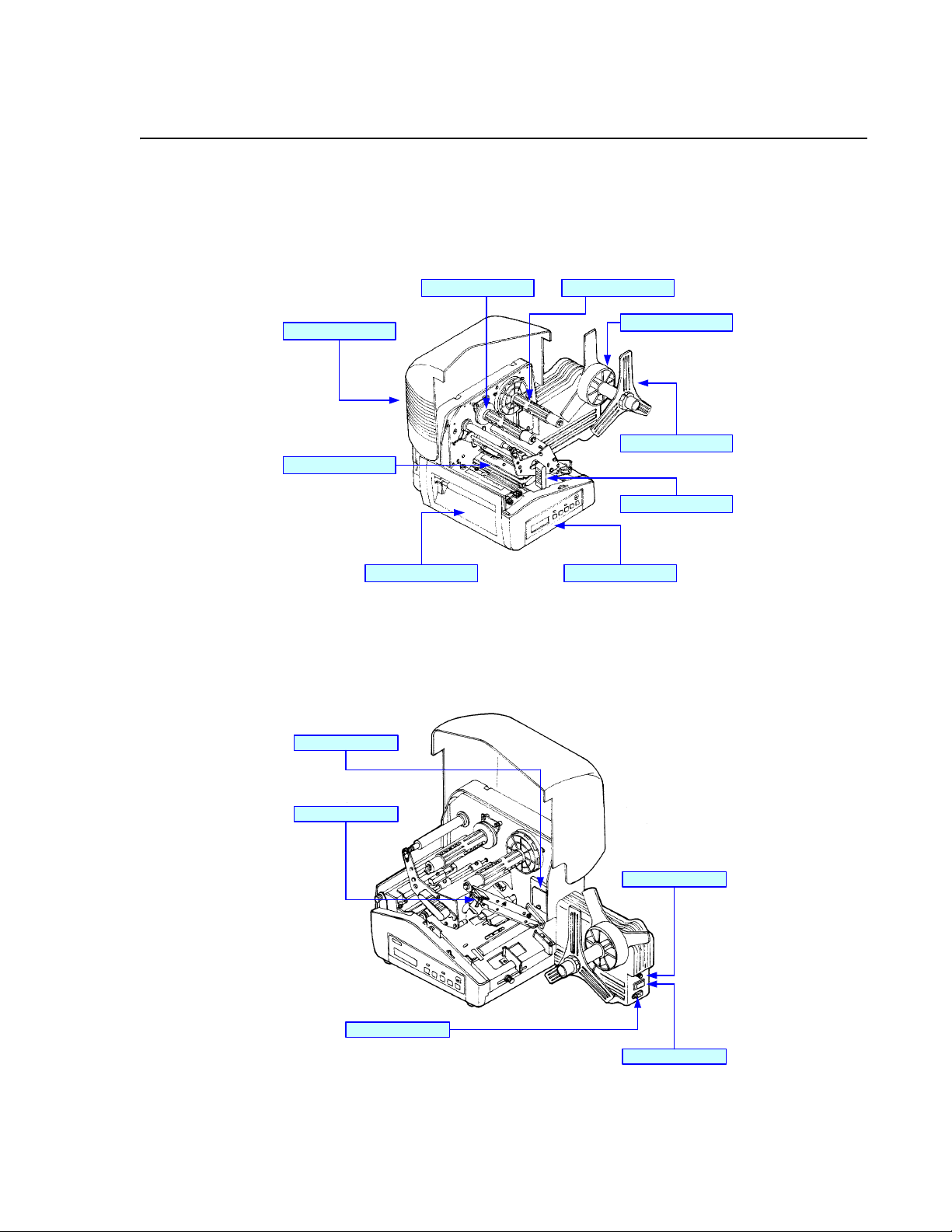
GENERAL DESCRIPTION
The XL400/410 “e” series printers are complete, high-performance labeling systems designed
specifically for printing labels and tags. All printer parameters are programmable using the front
panel controls and dip switches to provide printing of all popular bar codes and fonts styles and
sizes.
Ribbon Unwind SpindleRibbon Rewind Spindle
Top Housing Cover
Print Head Assembly
Adjustment Panel
Media Supply Spindle
Media Retaining Plate
Head Latch Lever
Operator PanelCutter Assembly
Figure 1-1a, Primary Components
Media Hold-Down
External Fuse
A/C Power Connector
Power Switch
Figure 1-1b, Primary Components
SATO XL400-410e Operator Manual PN 9001135A Page 1-3
Page 10

Unit 1: Introduction
CONTROL FEATURES
BUTTONS & SWITCHES
POWER Two position on/off switch that controls power flow to the system.
START / STOP Toggles the printer on/off line.
FEED Allows feeding of one tag or label each time it is pressed. Is only
functional when the printer is off-line. Feeds one label when the
cutter is disabled. Feeds one label, cuts, and backfeeds when the
cutter is enabled.
CUTTER ON/OFF Enables or disables the cutter. Is only functional when the printer is
off-line.
EJECT Feeds out any printed media. If the cutter is enabled; it feeds, cuts,
and backfeeds. If cutter is disabled; it ejects, cuts, and backfeeds.
MEDIA TYPE Allows the selection of the applicable media to be printed.
DSW1 & DSW2 Used to configure RS232 interface. Located behind access panel
inside the printer.
DSW3 Is largely reserved. Located behind access panel inside the printer.
VR1
VR2
VR3
VR4
DARKNESS
CUT
POSITION
PRINT
POSITION
DISPLAY
Reference Label
DSW 1
DSW 2
DSW 3
Potentiometers Dip Switches
Figure 1-2a, Control Features
SATO XL400-410e Operator Manual PN 9001135A Page 1-4
Page 11

Unit 1: Introduction
LED’s
SATO XL Printer
LCD Display
ON LINE
START
/STOP
CUTTER
FEED EJECT MEDIA TYPE
ON/OFF
Function Keys
ERROR
Figure 1-2b, Control Features
CONNECTION PORTS
AC Power Input Connector permits 115V, 50/60 Hz supply via supplied cord.
Interface Port Connector for interface harness. Must be connected for the printer to
be operational. Acceptable interface types are:
• RS232C Serial I/F Module, DB-25
• Parallel
• Universal Serial Bus Adapter
• Ethernet 10/100 BaseT I/F Module
• RS422/485 I/F Module, DB-9
Ext. Interface Port Connector for external control of print cycle. Also supplies power for
optional accessories - AMP 57-60140
Memory Card Slot Slot for the insertion of optional PCMCIA Memory Card
Memory Card Slot
Seria l Interface Port
Interface Port
Accessory Port
Figure 1-3, Connection Ports
SATO XL400-410e Operator Manual PN 9001135A Page 1-5
Page 12

Unit 1: Introduction
SATO XL400-410e Operator Manual PN 9001135A Page 1-6
Page 13

TECHNICAL DATA
• Physical Charcteristics
• Enviromental
•Power
• Processing
•Print
• Sensing
•Media
• Character Font Capabilities
• Barcode Capabilities
• Interface Modules
• Regulatory Approvals
SATO XL400-410e Operator Manual PN 9001135A Page 2-1
Page 14

Unit 2: Technical Data
PHYSICAL CHARACTERISTICS
Width 19.6 Inches (302 mm)
Height 11.50 Inches (294 mm)
Depth 11.80 Inches (552 mm)
Weight 30.80 Pounds (14.0 Kg) standard
ENVIRONMENTAL
Operating Temperature 41° to 104°F (5° to 40°C)
Storage Temperature 0° to 104°F (-20° to 40°C)
Storage Humidity Max 90% RH, Non-Condensing
Operating Humidity 15 to 85% RH, Non-Condensing
Electrostatic Discharge 8kV
POWER
Input Voltage 115/220 Volts AC +/- 10%, 50/60 Hertz +/-1%
Power Consumption 150 Watts Operating
PROCESSING
CPU 32 Bit RISC
FLash ROM 2 Mega-Bytes
SDRAM 16 Mega-Bytes
Receive Buffer 2.95 Mega-Bytes
Memory Expansion See Options and Accessories
PRINT
Method Direct Thermal / Thermal Transfer
Speed (user selectable) 2, 3, 4, 5, 6 Inches Per Second
Print Module (dot size) .0049 Inches (.125 mm)
Resolution XL400e: 203 Dots Per Inch (8 dpmm)
XL410e: 305 Dots Per Inch (12 dpmm)
Maximum Print Width 4.4 Inches (112 mm)
Maximum Print Length 14.0 Inches (355 mm)
SENSING
Gap Fixed
Reflective Eye-Mark Fixed
Continuous Form Sensor not used.
SATO XL400-410e Operator Manual PN 9001135A Page 2-2
Page 15
Unit 2: Technical Data
MEDIA
Eye-Mark Label Dimensions
Gap Label Dimensions
Eye-Mark Tag
Side Hole Tag
Center Hole Tag
R-Corner Tag
Maximum Caliper .008 Inches (.21 mm)
Maximum Roll Diameter 6 Inches (152 mm), Wound face inward
Minimum Core Diameter 3 Inches (76 mm)
Width: 1.26 to 3.94 Inches (32-100mm)
Length: 1.00 to 9.45 Inches (25-240mm)
Width: 1.00 to 3.94 Inches (25-100mm)
Length: 0.63 to 9.33 Inches (16-237mm)
Width: 1.26 to 3.94 Inches (32-100mm)
Length: 1.00 to 9.45 Inches (25-240mm)
Width: 2.00 to 3.94 Inches (50-100mm)
Length: 1.00 to 9.45 Inches (25-240mm)
Width: 1.26 to 3.94 Inches (32-100mm)
Length: 1.00 to 9.45 Inches (25-240mm)
Width: 1.26 to 3.94 Inches (32-100mm)
Length: 1.00 to 9.45 Inches (25-240mm)
CHARACTER FONT CAPABILITIES
MATRIX FONTS
XCS Font 24 dots W x 24 dots H (Care Symbol)
XCL Font 36 dots W x 36 dots H (Care Symbol)
XU Font 5 dots W x 9 dots H (Helvetica)
XS Font 17 dots W x 17 dots H (Univers Condensed Bold)
XM Font 24 dots W x 24 dots H (Univers Condensed Bold)
OA Font (OCR-A) XL400e: 15 dots W x 22 dots H
XL410e: 22 dots W x 33 dots H
OB Font (OCR-B) XL400e: 20 dots W x 24 dots H
XL410e: 30 dots W x 36 dots H
AUTO SMOOTHING FONTS
XB 48 dots W x 48 dots H (Univers Condensed Bold)
XL 48 dots W x 48 dots H (Sans Serif)
VECTOR FONT
Proportional or Fixed Spacing
Font Size 50 x 50 dots to 999 x 999 dots,10 Font Variations
DOWNLOADABLE FONTS
True Type Fonts with Optional Memory Upgrade
CHARACTER CONTROL
Expansion up to 12 x in either the X or Y coordinates.
Charcter Pitch & Line Space Control, Journal Print facility
0, 90, 180, and 270 Degree Rotation
SATO XL400-410e Operator Manual PN 9001135A Page 2-3
Page 16
Unit 2: Technical Data
BAR CODE CAPABILTIES
Linear Bar Codes Bookland (UPC/EAN Supplemental
EAN-8, EAN-13
CODABAR
Code 39
Code 128
Interleaved 2 of 5
UCC/EAN-128
UPC-A and UPC-E
Two Dimemsional Data Matrix
Maxicode
PDF417
Ratios 1:2, 1:3, 2:5, User definable bar widths
Bar Height 4 to 600 dots, User progammable
Rotation 0, 90, 180, and 270 Degrees
Sequential Numbering Sequential numbering of both numerics and bar codes
Custom Characters RAM storage for special characters
Graphics Full dot addressable graphics, SATO Hex/Binary, PCX formats
Form Overlay Form overlay for high-speed editing of complex formats
INTERFACE MODULES
Parallel Port IEEE 1284 Standard
Serial Port RS232C (9,600 to 19,200 dps) Standard
RS422/485 (9,600 to 57,600 bps) Optional
Universal Serial Bus USB Adapter
Ethernet 802.11B Wireless
Data Transmission ASCII Format
REGULATORY APPROVALS
Safety UL, CSA
RFI / EMI FCC Class A
SATO XL400-410e Operator Manual PN 9001135A Page 2-4
Page 17

INSTALLATION
• Unpacking
• Parts Identification
• Printer Installation
• Interface Selection
• Accessories Installation
SATO XL400-410e Operator Manual PN 9001135A Page 3-1
Page 18
Unit 3: Installation
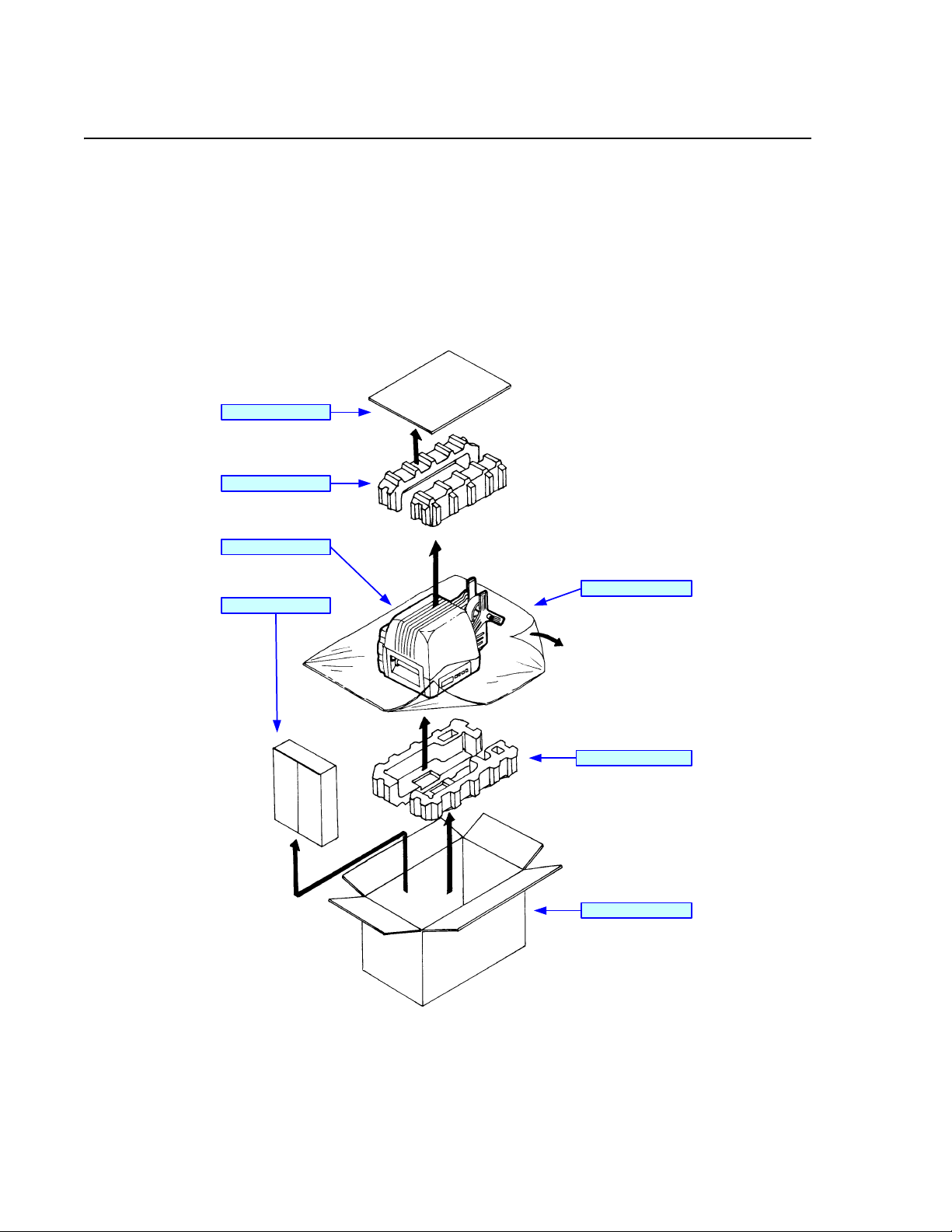
UNPACKING & PARTS IDENTIFICATION
Place the shipping container upright on a solid, flat surface. Open the container and remove the
carboard cover and top foam inserts. Carefully lift the printer from the shipping container,
followed by the acccessory box, and place them on a solid flat surface. Remove the plastic wrap
from the printer and its accessories. Inspect the printer and its accessories for visual physical
damage and ensure all components are present and report damaged property. Retain the
shipping container, foam inserts, and plastic wrap in case future return is necessary.
Cardboard Cover
Top Foam Inserts
XL Printer
Accessory Box
Protective Wrap
Bottom Foam Inserts
Shipping Container
Figure 3-1, Unpacking and Parts Identification
SATO XL400-410e Operator Manual PN 9001135A Page 3-2
Page 19
Unit 3: Installation
PRINTER INSTALLATION
This chapter provides guidance on general printer setup and installation. The following chapter
provides instructions on how to select an interface for the host to communicate with the printer.
SITE LOCATION
• Stationed on a solid flat surface
• Stationed away from hazardous conditions
• Sufficient access space on all sides to premit access and opening of its covers.
• Stationed within operational distance of the host computer.
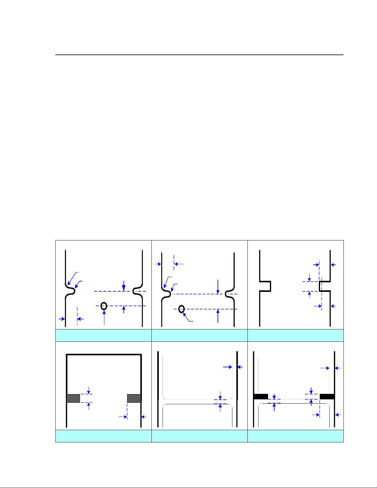
MEDIA SELECTION
The size and type of the labels or tags to be printed should have been taken into consideration
before printer purchase. Ideally, the media width will be equal to, or just narrower than, the print
head. Using media that does not cover the print head, will allow the platen roller to tread on the
head and cause premature wear. The edge of the media will also wear a groove in the platen
roller which will effect print quality.
After determining the width and length of the label or tag to be printed, and knowing the print
head width, order the media width of the print head and with the labels or tags oriented so that
the media’s space is optimized. The media should be wound with its print surface inward.
3mm
3R
1R
5mm
3mm
3R
1R
2.6 Dia.
5mm
Sensor Positi on 2.5mm
Center Hole Tag Side Hole Tag R-Corner Tag
1.5mm
<3.75mm
2.5mm
1.5mm
3.0mm
14.0mm
3.0mm
3.0mm
3.0mm
14.0mm
Eye-Mark Tag Gap Label Eye-Mark Label
SATO XL400-410e Operator Manual PN 9001135A Page 3-3
Page 20

Unit 3: Installation
MEDIA LOADING
Perform the following steps to load media into the printer. This procedure covers only the
physical installation of media and is applicable regardless of the media type. Refer to the
Configuration unit for setup instructions.
1 Switch the printer power switch off and disconnect the power supply cord (Figure 3-3a).
2 Open the top housing cover.
3 Remove the media retaining plate from media supply spindle (Figure 3-3b).
4 Insert media onto the media supply spindle followed by the media retaining plate.
5 Release print head latch and hinged media hold-down (Figure 3-3c).
6 Feed the media up the media ramp to its respective position (Figure 3-3d).
NOTE: Feed label media onto the platen roller. Tag media is to be fed onto
the feed roller.
7 Loosen set screw and manually adjust paper guide inward until media is denied lateral
movement. Retighten set screw.
8 Lower and latch media hold-down, print head assembly, and top cover (Figure 3-3e).
9 Restore power and test print label (Figure 3-3f).
Top Housing Cover
Power Supply Cord
Power Switch
Figure 3-3a, Media Loading
SATO XL400-410e Operator Manual PN 9001135A Page 3-4
Page 21

Unit 3: Installation
Media Supply Spindle
Media
Media Retaining Plate
Figure 3-3b, Media Loading
Media Hold-Down
Print Head Latch
Figure 3-3c, Media Loading
SATO XL400-410e Operator Manual PN 9001135A Page 3-5
Page 22
Unit 3: Installation
Cutter Assembly
Media
Media Ramp
Set Screw Paper Guide
Figure 3-3d, Media Loading
Top Housing Cover
Media Hold-DownPrint Head Assembly
Figure 3-3e, Media Loading
SATO XL400-410e Operator Manual PN 9001135A Page 3-6
Page 23

Unit 3: Installation
Label/Tag
Power Switch
Figure 3-3f, Media Loading
RIBBON LOADING
Perform the following steps to load the printer with ribbon. This procedure covers only the
physical installation of ribbon. Refer to the Configuration unit for setup instructions.
1 Switch the printer power switch off and disconnect the power supply cord (Figure 3-4a).
2 Open the top housing cover.
3 Release the print head latch (Figure 3-4b).
4 Insert ribbon roll onto the ribbon unwind spindle to unwind counter-clockwise (Figure 3-4c).
5 Insert a ribbon core onto the ribbon rewind spindle.
6 Route the free end of the ribbon around the print assembly (Figure 3-4d).
7 Tape the free end of the ribbon to the ribbon core (Figure 3-4e).
8 Rotate the ribbon rewind spindle clockwise until several layers of ribbon are on the core.
9 Lower the print head latch sandwiching the media and ribbon together (Figure 3-4f).
10 Close top housing cover.
11 Restore power and test print label (Figure 3-4g).
SATO XL400-410e Operator Manual PN 9001135A Page 3-7
Page 24

Unit 3: Installation
Top Housing Cover
Power Switch
Power Supply Cord
Figure 3-4a, Ribbon Loading
Ribbon
Print Assembly
Figure 3-4b, Ribbon Loading
SATO XL400-410e Operator Manual PN 9001135A Page 3-8
Page 25

Unit 3: Installation
Ribbon Unwind SpindleRibbon Rewind Spindle
Ribbon Roll
Ribbon Core
Figure 3-4c, Ribbon Loading
Ribbon
Print Assembly
Figure 3-4d, Ribbon Loading
SATO XL400-410e Operator Manual PN 9001135A Page 3-9
Page 26

Unit 3: Installation
Ribbon
Ribbon Core
Figure 3-4e, Ribbon Loading
Print Head Latch
Top Housing Cover
Ribbon
Figure 3-4f, Ribbon Loading
SATO XL400-410e Operator Manual PN 9001135A Page 3-10
Page 27
Unit 3: Installation
Label/Tag
Power Switch
Figure 3-4g, Ribbon Loading
SATO XL400-410e Operator Manual PN 9001135A Page 3-11
Page 28

Unit 3: Installation
INTERFACE SELECTION
This chapter presents the printer interface types and their specifications. These specifications
include detailed information to assist in the selection of the most appropriate method for the
printer to interface with the host. The four acceptable interface methods are:
• RS232C Asynchronous Serial
• IEEE1284 Parallel
• Universal Serial Bus (USB) Adapter
• Local Area network (LAN) Ethernet
• 802.11B Wireless
Following the selection of the desired interface, proceed to the next unit for instructions on how to
Configure the printer for that interface type.
WARNING: NEVER CONNECT OR DISCONNECT INTERFACE CABLES
(OR USE A SWITCH BOX) WITH POWER APPLIED TO EITHER THE
HOST OR THE PRINTER. THIS MAY CAUSE DAMAGE TO THE
INTERFACE CIRCUITRY IN THE PRINTER/HOST AND IS NOT COVERED
BY WARRANTY.
NOTE: Some hosts monitor the Request-To-Send (RTS) signal (pin 4 of 25)
to determine if the printer is ready to receive data. Since the printer does not
generate this signal, the RTS line must be held true (high) in order to allow
communication. This can be performed by connecting the RTS pin to the
Clear-To-Send (CTS) signal (pin 5 of 25).
RS232 SERIAL INTERFACE
This High Speed Serial Interface is a Plug-In Interface Module that can be installed in the printer
by the user. The only difference between this interface and the TTL is their signal levels and
cable pinouts.
RS232C SPECIFICATIONS
Asynchronous ASCII Half-duplex communication
Bi-Directional Communication
Data Transmission Rate 9600, 19200, 38400, 57600 bps
Data Length 8 bit (selectable)
Stop Bit 1 bit (fixed)
Parity Bit ODD, EVEN, NONE (selectable)
Codes Used ASC II Character Codes, JIS Kanji Codes
Control Codes STX (02H), ETX (03H), ACK (06H), NAK (15H)
Connector Special
Cable Special
Signal Levels High = +5V to +12V, Low = -5V to -12V
SATO XL400-410e Operator Manual PN 9001135A Page 3-12
Page 29
Unit 3: Installation
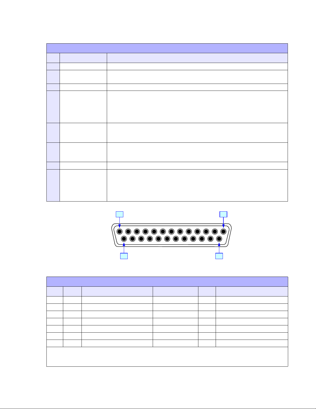
RS232C SERIAL INTERFACE SIGNALS
PIN DIRECTION SIGNAL DEFINITION
1 Reference FG (Frame Ground)
2 To Host TD (Transmit Data) - Data from the printer to the host computer. Sends X-On/
X-Off characters or status data (bi-directional protocols).
3 To Printer RD (Receive Data) - Data to the printer from the host computer.
4 To Host RTS (Request to Send) - Used with Ready/Busy flow control to indicate an
error condition. RTS is high and remains high unless the print head is open (in
this case, RTS would return to the high state after the print head is closed and
the printer is placed back on-line) or an error condition occurs during printing
(e.g., ribbon out, label out).
5 To Printer CTS (Clear to Send) - When this line is high, the printer assumes that data is
ready to be transmitted. The printer will not receive data when this line is low. If
this line is not being used, it should be tied high (to pin 4).
6 To Printer DSR (Data Set Ready) - When this line is high, the printer will be ready to
receive data. This line must be high before data is transmitted. If this line is not
being used, it should be tied high (to pin 20).
7 Reference SG (Signal Ground)
20 To Host DTR (Data Terminally Ready) - This signal applies to Ready/Busy flow control.
The printer is ready to receive data when this pin is high. It goes low when the
printer is off-line, either manually or due to an error condition, and while
printing in the single job buffer mode. It will also go low when the data in the
buffer reaches the buffer near full level.
113
1425
Figure 3-5, Serial Connector Pin Asignments
CABLE REQUIREMENTS
DB9 DB25 HOST CONNECTION DB9 PRINTER
1 1 FG (Frame Ground) Bi-Directional 1 FG (Frame Ground)
2 3 RD (Receive Data) To Host 2 TD (Transmit Data)
3 2 TD Transmit Data) To Printer 3 RD (Receive Data)
8 5 CTS (Clear To Send) To Printer DB9-6 4 RTS (Request to Send)
4 20 DTR (Data Terminal Ready) To Printer DB9-4 6 DSR (Data Set Ready)
6 6 DSR* (Data Set Ready) To Host 9 DTR (Data Terminal Ready)
5 7 SG (Signal Ground) Bi-Directional 7 SG (Signal Ground)
* This connection at the host side of the interface would depend upon the pin that is being used as the
Ready/Busy signal by the driving software. Typically, on a PC, it would be either CTS (pin5) or DSR (pin
6) on a DB-25 connector.
SATO XL400-410e Operator Manual PN 9001135A Page 3-13
Page 30

Unit 3: Installation
IEEE1284 PARALLEL INTERFACE
The parallel interface is a Plug-In, bi-directional, Interface Module that can be installed by the
user. It conforms to the IEEE1284 specification. It will automatically detect the IEEE1284 signals
and operate in the high speed mode. If it does not detect the IEEE1284 signals, it will operate in
the standard Centronics mode, which is significantly slower. For this reason, an interface cable
and host interface conforming to the IEEE1284 specification must be present to fully utilize the
speed capabilities.
SPECIFICATIONS
Printer Connector AMP 57-40360 DDK (or equivalent)
Cable Connector AMP 57-30360 DDK (or equivalent)
Cable IEEE1284 Parallel, 10 ft. (3 m) or less
Signal Level High = +2.4V to +5.0V, Low = 0V to -0.4V
Data Stream <ESC>A . . Job#1 . . <ESC>Z<ESC>A . . Job#n . . <ESC>Z
18
36
1
19
Figure 3-6, Parallel Connector Pin Asignments
IEEE 1284 PARALLEL INTERFACE PIN ASSIGNMENTS
PIN SIGNAL DIRECTION PIN SIGNAL DIRECTION
1 Strobe To Printer 19 Strobe Return Reference
2 Data 1 To Printer 20 Data 1 Return Reference
3 Data 2 To Printer 21 Data 2 Return Reference
4 Data 3 To Printer 22 Data 3 Return Reference
5 Data 4 To Printer 23 Data 4 Return Reference
6 Data 5 To Printer 24 Data 5 Return Reference
7 Data 6 To Printer 25 Data 6 Return Reference
8 Data 7 To Printer 26 Data 7 Return Reference
9 Data 8 To Printer 27 Data 8 Return Reference
10 ACK To Host 28 ACK Return Reference
11 Busy To Host 29 Busy Return Reference
12 Ptr Error To Host 30 PE Return Reference
13 Select To Host 31 INIT From Host
14 AutoFD1 To H os t 32 Fault To Host
15 Not Used 33 Not Used
16 Logic Gnd 34 Not Used
17 FG Frame Gnd 35 Not Used
18 +5V (z=24k ohm) To Host 36 SelectIn1 From Host
1 Signals required for ieee 1284 mode.
SATO XL400-410e Operator Manual PN 9001135A Page 3-14
Page 31

Unit 3: Installation
UNIVERSAL SERIAL BUS (USB) ADAPTER
The Universal Serial Bus (USB) interface is a Plug-In Interface Module that can be installed by
the user. It requires a driver (shipped with each printer that has the interface installed) that must
be loaded on your PC and the PC must be configured to support USB peripherals using Windows
98 or above. Details for loading the USB driver are contained in the USB Interface Manual that is
shipped with each printer with a USB Optional interface installed. Up to 127 devices may be
connected to a USB port using powered hubs.
SPECIFICATIONS
Printer Connector USB Type B Plug
Cable 10 feet (3 m) maximum
Host Windows 98 or above with USB Port
Power Supply BUS Power through cable
Power Consumption +5 V at 80 ma
LOCAL AREA NETWORK (LAN) ETHERNET
A Local Area Network (LAN) interface is an optional Plug-In Interface Module that can be
installed by the user. It requires a driver shipped with each printer that has the interface installed.
The driver that must be loaded on your PC and the PC must be configured to run one of the
supported network protocols using a 10/100BaseT LAN connection. Details for loading the LAN
driver are contained in the LAN Interface Manual that is shipped with each printer with a LAN
Optional interface installed.
SPECIFICATIONS
Connector RJ-45 Receptacle
Cable 10/100BaseT Category 5
Power Supply Powered from printer
802.11B WIRELESS
The wireless print server provides easy printer interface with 802.11b Wi-Fi compliant networks
free of wired connections. Each printer is shipped with an integrated driver and interface
installed. The driver must be loaded on your PC and the PC must be configured to run one of the
supported protocols.
80211B WIRELESS SPECIFICATIONS
Variable Data Rates 11, 5.5, 2 and 1 Mbps
Frequency Band 2.4 GHz ISM Band
Wired Equivalent Privacy 128 bit, 64 bit (compatible with 40bit), none
Sensitivity (typ, AAWGN, 8E-2 PER): -91dBm at 1Mbps, -88dBm at 2 Mdps,
-87dBm at 5.5Mbps, -84dBm at 11Mbps.
Range 100m indoors, 300m outdoors
Protocols TCP/IP, IPX/SPX, Direct Mode IPX/IP, DLC/LLC, NetBEUI,
NetBIOS/IP
SATO XL400-410e Operator Manual PN 9001135A Page 3-15
Page 32

Unit 3: Installation
RECEIVE BUFFER
The data stream is received from the host to the printer one job at a time. This allows the
software program to maintain control of the job print queue so that it can move a high priority job
in front of ones of lesser importance.
A multiple job buffer allows the printer to continuously receive print jobs while compiling and
printing other jobs at the same time. It acts much like a Print buffer to maximize the performance
of the host and the printer.
The printer receives and prints one job at a time. If a print job exceeds the buffer size,
transmission will be rejected by the printer. Flow control protocols to throttle transmission are not
used. Error conditions that occur during the Print Data transmission will cause the printer to
return a NAK.
ACK/NAK PROTOCOL
Bi-Directional ACK/NAK protocol is used for error control. In a normal transmission sequence
when the transmission is received, the printer will return an ACK (06H) signifying that it was
received without a transmission error. After the transmission command structure has been
analyzed, a status byte is returned to the host. This status byte informs the host of the validity of
the command structure.
If the command structure is error free, the printer proceeds with the print operation. When the
print operation is completed, a Printer Status message is returned to the host. If an error was
detected during the initial transmission sequence, a NAK (15H) will be returned signalling to the
host that the received transmission contained errors and must be resent. If the returned Status
byte indicates a command structure error, the error must then be corrected before the print data
is resent to the printer.
A valid transmission to the printer must be bounded by an STX/ETX pair, with the STX (02H)
signifying the start of the Print Data and ending with an ETX (03H) signifying the end.
SATO XL400-410e Operator Manual PN 9001135A Page 3-16
Page 33

Unit 3: Installation
ACCESSORIES INSTALLATION
In most instances, the printer is ordered with the desired accessories pre-installed. However,
changes in printing conditions or requirements does warrant upgrades from time to time.
This chapter of the manual covers the installation procedures of accessories that are deemed
suitable for the owner/operator to perform. For all other accessory upgrades or installatins,
contact the SATO Technical Support Dept.
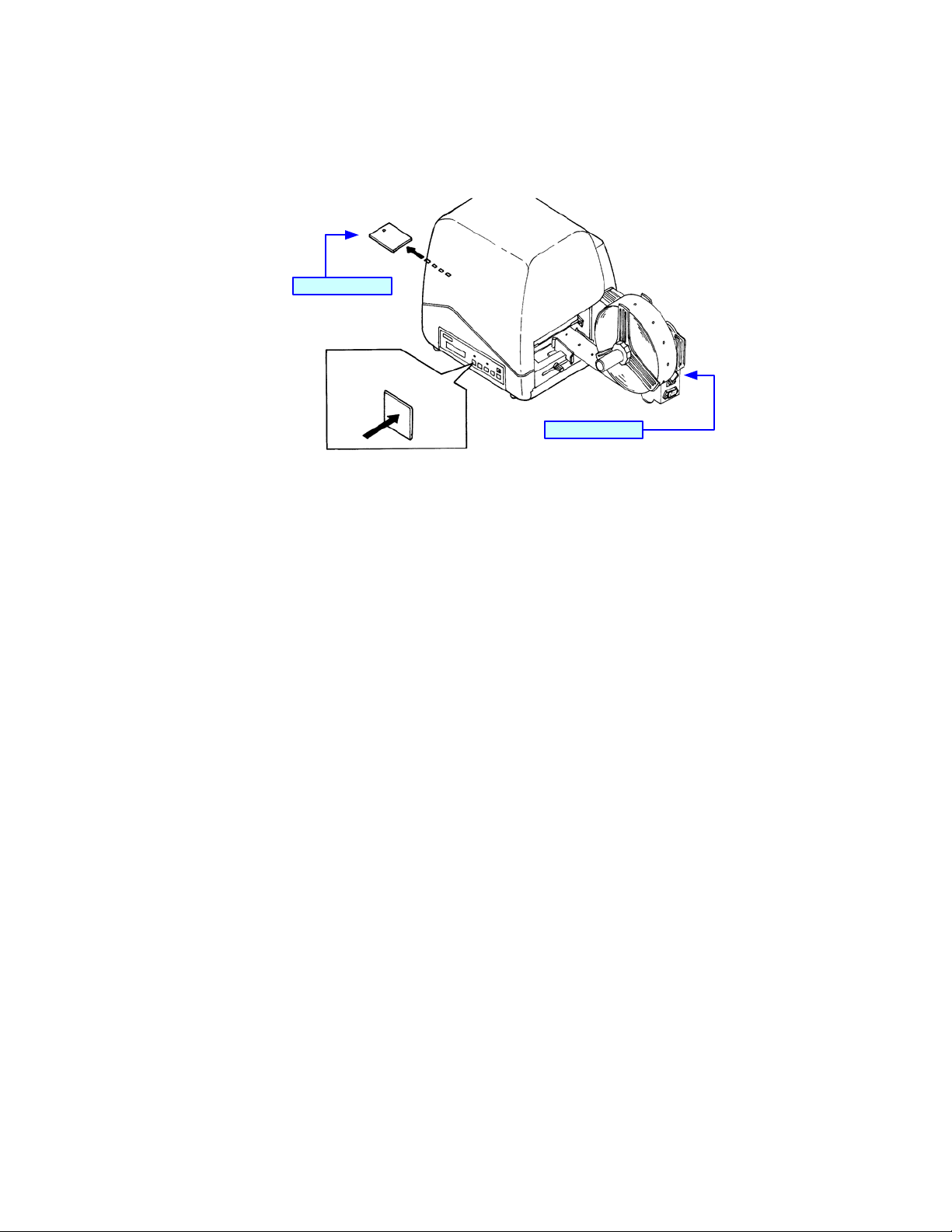
PCMCIA MEMORY UPGRADE
The memory card upgrade allows printer memory to be expanded from 2MB to 4MB. The card
may be installed by simply removing the access cover from the face of the printer and inserting
the card into the exposed slot.
Memory Card Slot
Figure 3-7, Memory Upgrade
SATO XL400-410e Operator Manual PN 9001135A Page 3-17
Page 34

Unit 3: Installation
STACKER UNIT
The XL Stacker Unit collects and stacks tags as they are printed and cut. Installation of the
included alignment plate ensures proper spacing and alignment of the stacker with the printer.
Connecting the stacker’s power cord to the Option port of the printer concludes installation.
Adjust the unit for operation in accordance with the instructions provided with the product.
Stacker Unit
Alignment Plate
XL Printer
Option Port
Figure 3-8, Label Stacker Installation
SATO XL400-410e Operator Manual PN 9001135A Page 3-18
Page 35

OPERATION
• Printer Configuration
• Configuration Modes
• Operational Adjustments
•Printing
SATO XL400-410e Operator Manual PN 9001135A Page 4-1
Page 36

Unit 4: Operation
PRINTER CONFIGURATION
The printer may be configured for specific jobs via the operator panel located on the right side of
the printer and the interface panel comprised of three dip switch complexes and four
potentiometers located within the printer’s interior. Each of these must be adjusted for full printer
configuration. The first step is to set the dip switches to their proper positions and then proceed
to the Configuration Modes and Operational Adjustments chapters to complete process.
DIP SWITCH PANELS
The following tables provide guidance on the enabling/disabling of various printer functions and
features. Determine what features are applicable to your setup, or desired setup, and adjust their
respective dip switches as applicable.
Each dip switch panel is an eight switch complex. Each switch is of a two position on/off toggle
type with the On position always oriented upward. To set the switches, first power the unit off,
then position the dip switches as required. After placing the dip switches in the desired positions,
power the printer back on. The switch settings are read by the printer electronics during the
power up sequence. They will not become effective until the power is cycled.
NOTE: There are three dip switch complexes and each are
numbered respectively. Each dip switch complex has eight switches
that are also numbered. Each of the following three tables
represents a single dip switch complex. The left column of each
table identifies the switch number and every column following that,
provides settings information.
CAUTION: NOT ALL OF THE SWITCHES WILL REQUIRE
ADJUSTMENT, CHANGE ONLY THOSE SWITCH SETTINGS
THAT ARE NECESSARY. LEAVE ALL OTHERS AT THEIR
DEFAULT POSITIONS.
SATO XL400-410e Operator Manual PN 9001135A Page 4-2
Page 37

Unit 4: Operation
DSW1 DEFAULT SETTINGS
1-1 1-2 1-3 1-4 1-5 1-6 1-7 1-8
OFFOFFOFFOFFOFFOFFOFFOFF
DSW1 CONFIGURATION
1-1 Data BIt
1-2
1-3
1-4 Stop Bit
1-5
1-6
1-7
1-8
Parity
Baud Rate
Protocol
OFF 8 Data Bit
ON 7 Data Bit
1-2 1-3
ON ON Reserved
ON OFF Odd
OFF ON Even
OFF OFF None
OFF 1 Stop Bit
ON 2 Stop Bit
1-5 1-6
ON ON Normal: 2400, High Speed: 57600
ON OFF Normal: 4800, High Speed: 38400
OFF ON Normal: 19200, High Speed: 19200
OFF OFF Normal: 9600, High Speed: 9600
1-7 1-8
ON ON Status 4
ON OFF Status 3
OFF ON XOn / XOff
OFF OFF Ready / Busy
DSW1 FUNCTION DESCRIPTIONS
FUNCTION DESCRIPTION
Data Bit
Parity Selects the type of parity used for error detection.
Stop Bit Selects the number of stop bits to end each byte transmission.
Baud Rate Select the data rate (bps) for the RS232 port.
Protocol Selects the flow control and status reporting protocols.
SATO XL400-410e Operator Manual PN 9001135A Page 4-3
Sets the printer to receive either 7 or 8 bits of data for each byte
transmitted.
Page 38

Unit 4: Operation
DSW2 DEFAULT SETTINGS
2-1 2-2 2-3 2-4 2-5 2-6 2-7 2-8
OFFOFFOFFOFFOFFOFFOFFOFF
DSW2 CONFIGURATION
DSW2 FUNCTION SETTING CONFIGURATION
2-1 Print Mode
2-2 Reserved
2-3 Head Check
2-4 Hex Dump
2-5 Receive Buffer
2-6 Firmware Download
2-7 Protocol Code
2-8 Operational Mode
DSW2 FUNCTION DESCRIPTIONS
OFF Thermal Transfer
ON Direct Thermal
OFF N/A
ON N/A
OFF Head Check Disabled
ON Head Check Enabled
OFF Hex Dump Disabled.
ON Hex Dump Enabled
OFF Single Job Receive Buffer
ON Multi-Job Receive Buffer
OFF Disabled
ON Enabled
OFF Standard Protocol Mode
ON Non-Standard Protocol Mode
OFF Standard Mode
ON Compatibility Mode
FUNCTION DESCRIPTION
Print Mode Print with the use of ribbon or without.
Head Check When enabled, will check for malfunctioning head elements.
Hex Dump Allows hexadecimal printing of all data received to the print buffer.
Receive Buffer
Firmware Download Places printer in mode for downloading software into flash ROM.
Protocol Code Selects the command codes used for protocol control.
Operational Mode Standard mode or for original XL400/410.
SATO XL400-410e Operator Manual PN 9001135A Page 4-4
Allows to continuously receive print jobs while compiling and printing
other jobs.
Page 39

Unit 4: Operation
DSW3 DEFAULT SETTINGS
3-1 3-2 3-3 3-4 3-5 3-6 3-7 3-8
OFFOFFOFFOFFOFFOFFOFFOFF
DSW3 CONFIGURATION
DSW1 FUNCTION SETTING CONFIGURATION
3-1 N/A
3-2 Pitch Size Check
3-3 N/A
3-4 N/A
3-5 N/A
3-6 N/A
3-7 N/A
3-8 N/A
DSW3 FUNCTION DESCRIPTIONS
OFF Reserved
ON Reserved
OFF Disabled
ON Enabled
OFF Reserved
ON Reserved
OFF Reserved
ON Reserved
OFF Reserved
ON Reserved
OFF Reserved
ON Reserved
OFF Reserved
ON Reserved
OFF Reserved
ON Reserved
FUNCTION DESCRIPTION
Pitch Check Checks the pitch size.
CONFIGURATION FOR LAN INTERFACE
DSW2-8 DSW2-5 PORT NUMBER COM STATUS DESCRIPTION
ON
OFF
SATO XL400-410e Operator Manual PN 9001135A Page 4-5
OFF 1 Port (1024: Bi-Directional) Status 3 ENQ Response
ON N/A N/A Reserved
OFF 2 Port (1024: Data Port)
ON Driver Protocol ENQ Response
(1025: Status Port)
Driver Protocol Periodic Response
Page 40

Unit 4: Operation
CONFIGURATION MODES
With exception of the Power switch located on the back side of the printer, all of the following
configuration activities are performed via the use of the operator panel located on the printer’s right
side and the adjustment panel located within the printer’s interior.
Many settings may also be controlled via software commands. In the case of conflict between the
software and control panel settings, the printer will always use the last entered valid setting.
NORMAL MODE
When a print job is received, the LCD will count off the label quantity as they are printed.
POWER
Printer
beeps
Display of media
selected.
MEDIA TYPE
To change
selection.
START/STOP to scroll.
PRINT SPEED
X X X X
START/STOP to scroll.
PRINT OFFSET
V: +000 H: +000
START/STOP
Display of media default
PRINT DARKNESS
1 2 3
FEED to select.
FEED to select.
START/STOP
or selection.
ONLINE
000000 00000000
START/STOP + FEED
PRINT OFFSET
V: +000 H: +000
START/STOP to scroll.
FEED to select.
ZERO SLASH
YES NO
START/STOP to scroll.
FEED to select.
CANCEL PRINT JOB
YES NO
START/STOP to scroll.
FEED to select.
CANCEL PRINT JOB
COMPLETED
3
seconds
transpires
START/STOP to scroll.
FEED to select.
Yes / No
START/STOP to scroll.
FEED to select.
Figure 4-1, Normal Mode
SATO XL400-410e Operator Manual PN 9001135A Page 4-6
Page 41

Unit 4: Operation
TEST PRINT MODE
This mode allows the operator to print test labels for troubleshooting and for verification of
configuration settings.
FEED + POWER
Printer
TEST PRINT MODE
CONFIGURATION
TEST PRINT MODE
BARCODE
TEST PRINT MODE
HEADCHECK
beeps
START/STOP
to scroll.
TEST PRINT MODE
MEMORY
TEST PRINT MODE
FACTORY
FEED
To select.
PRINT SIZE
03CM
START/STOP to scroll.
FEED to select.
USER TEST PRINT
PRESS FEED KEY
FEED
Printing
completes.
POWER
Off
FEED
To select.
PRINT SIZE
LARGE SMALL
Printing
commences.
FEED
FEED
Printing
ceases.
Figure 4-2, Test Print Mode
SATO XL400-410e Operator Manual PN 9001135A Page 4-7
Page 42

Unit 4: Operation
ADVANCED MODE
The Advanced Mode is provided to make basic printer operational adjustments. Typically, once
these adjustments or settings have been made, they will not require additional address unless a
new job is downloaded. The following table identifies the menus of the Advanced Mode and their
purpose.
START/STOP + POWER
Printer
beeps
SET CALENDAR
YES NO
START/STOP to scroll.
FEED to select.
CALENDAR
00 / 00 / 00 00:00
START/STOP to scroll.
FEED to select.
If calendar
is installed.
ADVANCED MODE
FEED
CHARACTER PITCH
PROP FIXED
START/STOP to scroll.
FEED to select.
EURO CODE
D5
START/STOP to scroll.
FEED to select.
If IEEE1284
is installed and
1 is selected.
IEEE1284
ACK SIGNAL 00.5
START/STOP to scroll.
FEED to select.
START/STOP
IGNORE CAN/DLE
YES NO
START/STOP to scroll.
FEED to select.
SELECT LANGUAGE
ENGLISH
START/STOP to scroll.
FEED to select.
CARD MODE
Refer to that
chart.
Figure 4-3, Advanced Mode
SATO XL400-410e Operator Manual PN 9001135A Page 4-8
Page 43

Unit 4: Operation
DEFAULT SETTINGS MODE
When the sequences have been completed, the printer automatically returns to its default gap or
eye-mark settings. The default settings are those programmed settings of the factory prior to
delivery.
START/STOP + FEED + POWER
Printer beeps.
DEFAULT SETTING
YES NO
Beeps
3 times and
returns default
settings.
DEFAULT SETTING
COMPLETED
Figure 4-4, Default Settings Mode
START/STOP to scroll.
FEED to select.
Yes / No
POWER = OFFFEED
SATO XL400-410e Operator Manual PN 9001135A Page 4-9
Page 44

Unit 4: Operation
FLASH MEMORY DOWNLOAD MODE
A Flash ROM internally stores and deletes font data and custom designed character data. The
storage capacity for custom characters is 95 for each type of 16 x 16, 22 x 22, and 24 x 24 dots.
There are four transmission protocols for font download: (1) Download Font Storage, (2)
Download Font Deletion, (3) Download Font Information Aquisition, (4) Storage CustomDesigned Character. The printer return status is set between STX (02H) and ETX (03H), and
transferred in 3 bytes. Note that the return status for the font data transfer when storing font is 1
byte of ACK (06H). All status data transferred from the host are set between STX (02H) and ETX
(03H), and transferred in 3 bytes.
DOWNLOAD FONT REGISTRATION
STATUS DESCRIPTION ACSII HEX TRANSFER
Not Already Stored A 41 Printer to Host
Already Stored B 42 Printer to Host
Storage Area NG N 4E Printer to Host
Store Font 0 30 Host to Printer
Do Not Store Font 1 31 Host to Printer
Ready For Storage Status O 4F Printer to Host
Font Storage Completed Normally E 45 Printer to Host
Font Storage Cancelled S 53 Printer to Host
Font Storage Completed Abnormally Z 5A Printer to Host
DOWNLOAD FONT DELETION
STATUS DESCRIPTION ACSII HEX TRANSFER
Not Already Stored A 41 Printer to Host
Already Stored B 42 Printer to Host
Delete Font 0 30 Host to Printer
Do Not Delete Font 1 31 Host to Printer
Font Deletion Completed Normally E 45 Printer to Host
Font Deletion Cancelled S 53 Printer to Host
Font Storage Completed Abnormally Z 5A Printer to Host
DOWNLOAD FONT INFORMATION AQUISTION
STATUS DESCRIPTION ACSII HEX TRANSFER
Not Already Stored A 41 Printer to Host
Already Stored B 42 Printer to Host
Font Information Transferred OK 0 30 Host to Printer
Number of Transferred Data 000000-999999 6 bytes w/30-39 Printer to Host
Font Information Font Info Data + Font Data Info Printer to Host
SATO XL400-410e Operator Manual PN 9001135A Page 4-10
Page 45

Unit 4: Operation
STORAGE OF CUSTOM DESIGNED CHARACTER
STATUS DESCRIPTION ACSII HEX TRANSFER
Storage Ready Status O 4F Printer to Host
Storage Completed Normally E 45 Printer to Host
Storage Completed Abnormally Z 5A Host to Printer
DSW2-6 = ON
POWER
DOWNLOAD
WAITING
Send data.
xxxxxxx DOWNLOAD
START >>>>>>> END
Printer begins
receiving data.
xxxxxxx DOWNLOAD
COMPLETED
More
than 3 seconds
transpires.
DSW2-6 = OFF
POWER = OFF
Figure 4-5, Flash Memory Download Mode
SATO XL400-410e Operator Manual PN 9001135A Page 4-11
Page 46

Unit 4: Operation
USER DOWNLOAD MODE
This download feature allows the operator to download print jobs to the printer. When
downloading is complete, the LCD screen will return to the original display after three seconds. If
an error occurs, a DOWNLOAD ERROR will display and identify the reason.
DSW2-7 = ON
START/STOP + POWER
Printer beeps.
USER DOWNLOAD
START/STOP
USER DOWNLOAD
WAITING
Send data from
host.
USER DOWNLOAD
DOWNLOADING
Printer
downloads
data.
USER DOWNLOAD
COMPLETE
FEED
POWER = OFF
DSW2-7 = OFF
Figure 4-6, User Download Mode
SATO XL400-410e Operator Manual PN 9001135A Page 4-12
Page 47

Unit 4: Operation
HEX DUMP MODE
The contents of the print buffer and the data received before it is placed into the print buffer may
be examined through the use of the Hex Dump Mode. Each line of the printed data is inumerated
in the first column, the second column contains the data in hexadecimal format, and the right
column contains the same data in ASCII format.
Print Buffer/Receive Buffer
POWER = ON
ONLINE
000000 00000000
Create and print
A label.
START/STOP
OFFLINE
000000 00000000
DSW2-4 = ON
START/STOP
ONLINE
000000 00000000
POWER = OFF
DSW2-4 = ON
POWER = ON
and transmit data.
ONLINE
000000 00000000
Receive Buffer
is printed in
hexadecimal
format.
DSW2-4 = OFF
POWER = OFF
and ON again.
Printer returns
to normal print
mode.
Label printed
FEED
of print buff er in
hexadecimal
format.
Figure 4-7, Hex Dump Mode
SATO XL400-410e Operator Manual PN 9001135A Page 4-13
Page 48

Unit 4: Operation
CARD MODE
This configuration mode is used for configuring the Flash ROM and/or PCMCIA interface cards.
The following table identifies the menus of the Card Mode and their purpose. The flow chart after,
sequences the operator, printer, and host interface activities.
START/STOP + POWER
Printer
beeps.
ADVANCED MODE
START/STOP
CARD MODE
FEED
MEM SELECT(CC1)
CARD MEMORY
START/STOP to scroll.
FEED to select.
CARD->MEMORYCOPY
ALL Y/N
START/STOP to scroll.
FEED to select.
Yes / No
COPY START
YES NO
START/STOP to scroll.
FEED to select.
Yes / No
Copy
begins
START/STOP
COPY START
YES NO
START/STOP to scroll.
FEED to select.
Yes / No
Copy
begins
FORMAT START
YES NO
Format
begins
MEMORY->CARDCOPY
ALL <0MB> Y/N
START/STOP to scroll.
FEED to select.
Yes / No
MEMORY->CARDCOPY
PROGRAM Y/N
START/STOP to scroll.
FEED to select.
Yes / No
START/STOP to scroll.
FEED to select.
Yes / No
CARD->MEMORYCOPY
PROGRAM Y/N
START/STOP to scroll.
FEED to select.
Yes / No
CARD FORMAT
YES NO
START/STOP to scroll.
MEMORY FORMAT
YES NO
START/STOP to scroll.
FEED to select.
Yes / No
FEED to select.
Yes / No
Figure 4-8, Card Mode
SATO XL400-410e Operator Manual PN 9001135A Page 4-14
Page 49

Unit 4: Operation
NON-STANDARD CLEAR MODE
Returns non standard protocol code to the default value. The default values are STX (7B), ETX
(7D), ESC (5E), ENQ (40), NUL (7E), CAN (21), OFFLINE (5D). Follow the sequences in th flow
chart below to perform this function.
DSW2-7 = ON
START/STOP + FEED + POWER
Printer emits
I long and
3 short
beeps.
ALT. PROTOCOL
DEFAULT COMPLETE
POWER = OFF
DSW2-7 = OFF
Figure 4-9, Non-Standard Clear Mode
SATO XL400-410e Operator Manual PN 9001135A Page 4-15
Page 50

Unit 4: Operation
SERVICE MODE
Allows the programming of various dimensional settings and the language used. Refer to the
table below for an explaination of each menu encountered. The following flow chart provides
configuration sequence.
DSW2-4 = ON
START/STOP + FEED + POWER
Printer
beeps
Refer to
Service Mode
Chart B
Refer to
Service Mode
Chart C
DSW2-4 = OFF
SERVICE MODE
TEST PRINT
FEED
COUNTER CLEAR
NONE
START/STOP
to scroll.
START/STOP
SERVICE MODE
SENSOR LEVEL
START/STOP
SERVICE MODE
PITCH OFFSET
SERVICE MODE
DIPSW2-4 ON->OFF
COUNTER CLEAR
ALL
COUNTER CLEAR
COUNTERS
COUNTER CLEAR
HEAD
COUNTER CLEAR
CUT
COUNTER CLEAR
LIFE
FEED
to select.
PRINT SIZE
SMALL LARGE
START/STOP to scroll.
FEED to select.
PRINT SIZE
3CM
START/STOP to scroll.
FEED to select.
SERVICE PRINT
PRESS FEED KEY
Press FEED to start
and stop printing.
Power = Off
to exit.
Refer to
Service Mode
Chart D
START/STOP
SERVICE MODE
CUT OFFSET
START/STOP
SERVICE MODE
BACKFEED OFFSET
Refer to
Service Mode
Chart E
START/STOP
SERVICE MODE
COUNTER DISPLAY
Refer to
Service Mode
Chart F
Figure 4-10a, Service Mode - Test Print
SATO XL400-410e Operator Manual PN 9001135A Page 4-16
Page 51

Unit 4: Operation
DSW2-4 = ON
START/STOP + FEED + POWER
SERVICE MODE
SENSOR LEVEL
START/STOP
Refer to
Service Mode
Chart A
Refer to
Service Mode
Chart C
Refer to
Service Mode
Chart D
Printer
beeps
SERVICE MODE
DIPSW2-4 ON->OFF
DSW2-4 = OFF
SERVICE MODE
TEST PRINT
START/STOP
SERVICE MODE
PITCH OFFSET
START/STOP
SERVICE MODE
CUT OFFSET
FEED
GAP [ x.x V ]
INPUT [ x.x V ]
START/STOP to scroll.
FEED to select.
EYE [ x.x V ]
INPUT [ x.x V ]
START/STOP to scroll.
FEED to select.
PAPER SENSOR
R-CORNER [ x ]
FEED
PAPER SENSOR
SIDE HOLE [ x ]
FEED
PAPER SENSOR
JUMP HOLE [ x ]
FEED
CUTTER SENSOR
CENTER HOLE [ x ]
FEED
CUTTER SENSOR
I-MARK [ x ]
FEED
CUTTER SENSOR
R-CORNER [ x ]
FEED
Refer to
Service Mode
Chart E
START/STOP
SERVICE MODE
BACKFEED OFFSET
START/STOP
SERVICE MODE
COUNTER DISPLAY
Refer to
Service Mode
Chart F
Figure 4-10b, Service Mode - Sensor Level
SATO XL400-410e Operator Manual PN 9001135A Page 4-17
Page 52

Unit 4: Operation
DSW2-4 = ON
START/STOP + FEED + POWER
Printer
beeps
SERVICE MODE
PITCH OFFSET
FEED
START/STOP
SERVICE MODE
DIPSW2-4 ON->OFF
DSW2-4 = OFF
SERVICE MODE
TEST PRINT
START/STOP
SERVICE MODE
SENSOR LEVEL
START/STOP
SERVICE MODE
CUT OFFSET
START/STOP
SERVICE MODE
BACKFEED OFFSET
PITCH OFFSET
CENTER HOLE +00
START/STOP to scroll.
FEED
Refer to
Service Mode
Chart D
Refer to
Service Mode
Chart E
PITCH OFFSET
I-MARK TAG +00
PITCH OFFSET
SIDE HOLE +00
PITCH OFFSET
R-CORNER TAG +00
PITCH OFFSET
LABEL GAP +00
PITCH OFFSET
LABEL I-MARK +00
START/STOP
SERVICE MODE
COUNTER DISPLAY
START/STOP
Refer to
Service Mode
Chart F
Figure 4-10c, Service Mode - Pitch Offset
SATO XL400-410e Operator Manual PN 9001135A Page 4-18
Page 53

Unit 4: Operation
DSW2-4 = ON
START/STOP + FEED + POWER
Printer
beeps
SERVICE MODE
CUT OFFSET
START/STOP
Refer to
Service Mode
Chart A
Refer to
Service Mode
Chart B
Refer to
Service Mode
Chart C
SERVICE MODE
DIPSW2-4 ON->OFF
DSW2-4 = OFF
SERVICE MODE
TEST PRINT
START/STOP
SERVICE MODE
SENSOR LEVEL
START/STOP
SERVICE MODE
PITCH OFFSET
START/STOP
FEED
CUT OFFSET
CENTER HOLE +00
START/STOP to scroll.
FEED
SERVICE MODE
BACKFEED OFFSET
START/STOP
SERVICE MODE
COUNTER DISPLAY
START/STOP
CUT OFFSET
I-MARK TAG +00
CUT OFFSET
SIDE HOLE TA +000
CUT OFFSET
R-CORNER TAG +000
CUT OFFSET
LABEL GAP +000
CUT OFFSET
LABEL I-MARK +000
CUT OFFSET
NOT SENSOR U+000
Refer to
Service Mode
Chart E
Refer to
Service Mode
Chart F
Figure 4-10d, Service Mode - Cut Offset
SATO XL400-410e Operator Manual PN 9001135A Page 4-19
Page 54

Unit 4: Operation
DSW2-4 = ON
START/STOP + FEED + POWER
Printer
beeps
SERVICE MODE
BACKFEED OFFSET
START/STOP
Refer to
Service Mode
Chart A
Refer to
Service Mode
Chart B
Refer to
Service Mode
Chart C
Refer to
Service Mode
Chart D
SERVICE MODE
DIPSW2-4 ON->OFF
DSW2-4 = OFF
SERVICE MODE
TEST PRINT
START/STOP
SERVICE MODE
SENSOR LEVEL
START/STOP
SERVICE MODE
PITCH OFFSET
START/STOP
SERVICE MODE
CUT OFFSET
START/STOP
FEED
BACKFEED OFFSET
CENTER HOLE +00
START/STOP to scroll.
FEED
SERVICE MODE
COUNTER DISPLAY
START/STOP
BACKFEED OFFSET
I-MARK TAG +00
BACKFEED OFFSET
SIDE HOLE TA +000
BACKFEED OFFSET
R-CORNER TAG +000
BACKFEED OFFSET
LABEL GAP +000
BACKFEED OFFSET
LABEL I-MARK +000
BACKFEED OFFSET
NOT SENSOR U+000
Refer to
Service Mode
Chart F
Figure 4-10e, Service Mode - Backfeed Offset
SATO XL400-410e Operator Manual PN 9001135A Page 4-20
Page 55

Unit 4: Operation
DSW2-4 = ON
START/STOP + FEED + POWER
Refer to
Service Mode
Chart A
Refer to
Service Mode
Chart B
Refer to
Service Mode
Chart C
Printer
beeps
SERVICE MODE
DIPSW2-4 ON->OFF
DSW2-4 = OFF
SERVICE MODE
TEST PRINT
START/STOP
SERVICE MODE
SENSOR LEVEL
START/STOP
SERVICE MODE
PITCH OFFSET
START/STOP
SERVICE MODE
COUNTER DISPLAY
FEED
COUNTER
LIFE X.X M
START/STOP to scroll.
START/STOP
COUNTER
HEAD X.X M
COUNTER
CUT X.X M
Refer to
Service Mode
Chart D
Refer to
Service Mode
Chart E
SERVICE MODE
CUT OFFSET
START/STOP
SERVICE MODE
BACKFEED OFFSET
START/STOP
Figure 4-10f, Service Mode - Counter Display
SATO XL400-410e Operator Manual PN 9001135A Page 4-21
Page 56

Unit 4: Operation
NORMAL MODE
MENU DESCRIPTION
NORMAL MODE Basic print functions.
ONLINE
000000 00000000
CENTER HOLE
000000 00000000
PRINT DARKNESS
X X X X
PRINT SPEED
X X X X X
PRINT OFFSET
V: +000 H: +000
ZERO SLASH
YES NO
CANCEL PRINT JOB
YES NO
CANCEL PRINT JOB
COMPLETED
Receives data and can issue a label. Displays the countdown
number and the count-up number in the lower region on the
LCD.
Center Hole is the factory default media. If another media has
been selected, that will be displayed. The countdown and
count-up quantites is also displayed.
Allows the selection of print density and displays the selection.
Allows the selection of printing speed and displays the
selection. The print speed options are determined by the printer
XL400e or XL410e being used. The lower digits are the slower
speeds and ascends with the numeral digits. The speed is
based on inches.
Allows the entry of the horizontal and vertical print offset and
displays the entry. The offset is determined by the number of
dots with a range of 0 to 400. Either + or - options allow for the
determination of a positive or negative numeral.
Allows for the zero slash to be enabled or disabled. Zero slash
enabled provides for a slash to be printed diagonally across the
numeral zero to differentiate it from the letter “O”.
Permits the print job to be aborted.
Confirms the print job has been canceled or aborted.
DEFAULT SETTINGS MODE
MENU DESCRIPTION
DEFAULT SETTING
YES NO
DEFAULT SETTING
COMPLETE
REturns the print density, print speed, offset correction, zero
slash, and character pitch to their initial values. Press the FEED
key to initiate. Switch power off to discontinue.
After confirming the settings, turn the power off.
NON-STANDARD CODE CLEAR
MENU DESCRIPTION
ALT. PROTOCOL
DEFAULT COMPLETE
SATO XL400-410e Operator Manual PN 9001135A Page 4-22
Allows the non-standard protocol code to its default values. The
default values are: STX (7B), ETX (7D), ESC (5E), ENQ (40),
NULL (7E), CAN (21), and Offline (5D).
Page 57

Unit 4: Operation
ADVANCED MODE
MENU DESCRIPTION
ADVANCED MODE Menu allows configuration of printer features that typically do
not require change.
CHARACTER PITCH The PROP option allows proportional pitch and the FIXED
option is without. The FIXED option sets printing so that each
font occupies the same amunt of lateral space regardless of a
given character width. For example, the character “i” would
occupy the same space laterally as the character “s” even
though the “s” is obviously wider. Proportional printing
accomidates printing to the width of each printed character.
Fonts XU, XS, XM, XB, XL, and X70 to X77 are valid.
EURO CODE Sets Euro Code. Selects the assigned code of the Euro mark.
The default value is D5 (HEX). START/STOP key moves the
cursor and the FEED key selects the option.
SET CALENDAR Displays only if the option is installed. This feature permits the
printing of the date and time of print occurance onto the label. If
the YES option is selected, a secondary menu will display for
date and time entry.
AUTO ONLINE Determines the mode in which the printer powers up. If the YES
option is selected, the printer will power up in the online mode
and ready to print. If the NO option is selected, the printer will
power up in the offline mode and will require to manually be
brought online.
IEEE1284
ACK SIGNAL 00.5
SELECT LANGUAGE Sets the language to be displayed on the LCD screen. There
Sets to ACK signal width of the IEEE1284. Displays only when
the IEEE1284 board is installed. The default value is 00.5.
are eight language options available. START/STOP key moves
the cursor and the FEED key selects the option.
FLASH MEMORY & USER DOWNLOAD MODES
MENU DESCRIPTION
DOWNLOAD
WAITING
xxxxxxxxxxx DOWNLOAD
DOWNLOADING
xxxxxxxxxxx DOWNLOAD
COMPLETED
DOWNLOAD ERROR
xxxxxxxx ERROR
SATO XL400-410e Operator Manual PN 9001135A Page 4-23
Indicates the printer is waiting for the program/font data to be
received from the host.
Indicates the current downloading mode.
Indicates the current download mode. After displaying the
message for 3 seconds, it auatomatically returns to the
selection display.
Indicates the contents of the error. Press FEED to return to the
selection screen.
Page 58

Unit 4: Operation
CARD MODE
MENU DESCRIPTION
CARD MODE Menu allows configuration of the memory card.
MEM SELECT(CC1)
CARD MEMORY
CARD->MEMORYCOPY
ALL Y/N
MEMORY->CARDCOPY
ALL <?MB> Y/N
CARD->MEMORYCOPY
PROGRAM Y/N
MEMORY->CARDCOPY
PROGRAM Y/N
CARD FORMAT
YES NO
MEMORY FORMAT Allows formatting of Flash ROM memory. START/STOP key
xxxxxxx START
YES NO
COPYING Displays that the copying or formatting activity is underway.
xxxxxxxxxxxxxxxxxxxxxxxxxxxxxxxx
COMPLETED
CARD COPY/FORMAT
ERROR
CARD ID ERROR
PRESS FEED KEY
Establishes the media of the first drive. The default value is on
the card. START/STOP key moves the cursor and the FEED
key selects the option.
Allows the copying of the entire card contents into Flash ROM.
START/STOP key moves the cursor and the FEED key selects
the option.
Allows the copying of the entire contents of the Flash ROM or
firmware. A 4MB card or greater is required. An error occurs if
an insufficient memory card is used.
Allows corying of Firmware program. Can overwrite the
Firmware program card in program ROM. A program card is
created by copying to the memory card of the Firmware
mentioned later.
Allows copying of the Firmware program in the memory card. A
2MB card or greater is required. START/STOP key moves the
cursor and the FEED key selects the option.
Allows formatting of the memory card and to clear all internal
contents. START/STOP key moves the cursor and the FEED
key selects the option.
moves the cursor and the FEED key selects the option.
Initiates the copying or formatting activity. START/STOP key
moves the cursor and the FEED key selects the option.
Displays that the copying or formatting activity is complete.
After 3 seconds of display, returns to the original screen.
Displays if the copying or formatting activity incuured an error
and could not complete. The FEED key returns the display to
the original screen.
Displays when the incorrect card has been selected. The FEED
key returns the display to the original screen.
USER TEST PRINT MODE
MENU DESCRIPTION
TEST PRINT MODE
CONFIGURATION
PRINT SIZE
03CM
USER TEST PRINT
PRESS FEED KEY
SATO XL400-410e Operator Manual PN 9001135A Page 4-24
Allows the selection of the desired test print type. Press START/
STOP to scroll the options and FEED to select.
Sets the width of test print media. START/STOP key moves the
cursor and the FEED key selects the option.
Initiates test printing. Press the FEED key to initiate test printing
and FEED again to interrupt.
Page 59

Unit 4: Operation
SERVICE MODE
MENU DESCRIPTION
SERVICE MODE Menu allows configuration media type.
COUNTER CLEAR
NONE
PRINT SIZE
SMALL LARGE
PRINT SIZE
3CM
SERVICE PRINT
PRESS FEED KEY
GAP x.xV
INPUT x.xV
I-MARK x.xV
INPUT x.xV
PAPER SENSOR
R-CORNER [X]
PAPER SENSOR
SIDE HOLE [X]
CUT OFFSET
CENTER HOLE +000
CUT OFFSET
CENTER HOLE +000
SERVICE MODE
BACKFEED OFFSET
BACKFEED OFFSET
CENTER HOLE +00
BACKFEED OFFSET
CENTER HOLE +00
SERVICE MODE
COUNTER DISPLAY
COUNTER DISPLAY
LIFE
Selects the counter to clear. The options are None, All, Print
Head, Cutter, and Dispenser. The default value is NONE: Do
not clear. START/STOP key moves the cursor and the FEED
key selects the option.
Sets the print size for the test print. START/STOP key moves
the cursor and the FEED key selects the option.
Sets the width of test print media. START/STOP key moves the
cursor and the FEED key selects the option.
Initiates test printing. Press the FEED key to initiate test printing
and FEED again to interrupt. Press EJECT to eject a label or
tag when printing is interrupted.
Sets slice level. Sets the threshold level between 0-3.2. When
the value is set at 0, auto setting is done through the firmware
software. START/STOP key moves the cursor and the FEED
key selects the option.
Sets the eye-mark sensor threshold. Sets the threshold level
between 0-3.2. When the value is set at 0, auto setting is done
through the firmware software. START/STOP key moves the
cursor and the FEED key selects the option.
Displays the status of the paper under the R-Corner Sensor (to
check the sensor only). When “0” is displayed, media is not
detected. When “1” is displayed, media is detected. The FEED
key advances to the next sensor display.
Displays the status of the paper under the Side Hole Sensor (to
check the sensor only). When “0” is displayed, media is not
detected. When “1” is displayed, media is detected. The FEED
key advances to the next sensor display.
Selects the media type to be set. Press START/STOP to scroll
the media options and the FEED key to select.
Sets the cut offset value. The range is +/- 0 to 999. Press
START/STOP to scroll the options in each field and FEED to
advance when each is set.
The FEED key shifts to backfeed offset settings and the START/
STOP key the Counter Display selection.
Selects the media type to be set. Press START/STOP to scroll
the media options and the FEED key to select.
Sets the cut offset value. The range is +/- 0 to 99. Press
START/STOP to scroll the options in each field and FEED to
advance when each is set.
The FEED key shifts to the Counter Display selection and the
START/STOP key the Counter Clear selection.
Selects the counter type to be displayed. Press START/STOP
to scroll options and the FEED key to select.
SATO XL400-410e Operator Manual PN 9001135A Page 4-25
Page 60

Unit 4: Operation
OPERATIONAL ADJUSTMENTS
These operational adjustments are for fine tuning the printer as necessary following the
configuration process and are confined to the three potentiometers located on the adjustment
panel in addition to the operator panel. Refer to the table below for their function.
POTENTIOMETER DESCRIPTION/PROCEDURE
DARKNESS (VR1) Is used to adjust the darkness or lightness of the printed image
and should be used in conjunction with the configuration
adjustments. Make course adjustments there and then fine tune
here. If unable to achieve the desired setting here, the course
adjustment must be reset.
Adjust this potentiometer as labels are being printed. Allow two
labels to be printed for each adjustment to ensure a desired
setting.
CUT POSITION (VR2) The offset adjustment is used to reposition the media for
printing following advancement for cutting and dispensing. A
label is printed, it is fed forward for dispense, the printer retracts
the remaining media (offset) to print the next label.
PRINT POSITION (VR3) Is to be used in conjunction with the configuration adjustments.
Make course adjustments there and then fine tune here. If
unable to achieve the desired setting here, the course
adjustment must be reset. Adjust this potentiometer as labels
are being printed. Allow two labels to be printed for each
adjustment to ensure a desired setting.
Adjustment of the Print Position potentiometer will affect the
print offset postion. Thusly, if using a dispenser or cutter, adjust
the Cut Position first and then the Print Position.
DISPLAY (VR4) This potentiometer allows illumination adjustment of the LCD
panel. To adjust, power on the printer and turm the VR4
potentiometer as necessary to achieve the desired results.
SATO XL400-410e Operator Manual PN 9001135A Page 4-26
Page 61

Unit 4: Operation
Reference Label
VR1
VR2
VR3
VR4
VR1
VR2
VR3
VR4
DARKNESS
CUT
POSITION
PRINT
POSITION
DISPLAY
DSW 1
DSW 2
DSW 3
Figure 4-11, Adjustment Panel
SATO XL400-410e Operator Manual PN 9001135A Page 4-27
Page 62

Unit 4: Operation
CUTTER SENSOR POSITIONING
The cutter assembly has dual adjustable sensors and is designed to permit lateral movement of
the sensor assembly to accomdate multiple media types. To position the sensor, loosen its set
screw and move the sensor assembly along the incremented scale to the correct position so that
it aligns with its reference mark on the media and then retighten the set screw. Then select which
of the dual sensors is also applicable to the media of use.
NOTE: In order for the sensor to function properly, it must be
correctly positioned and the switch properly set for the applicable
media. If the cutter assembly still does not operate correctly, the
sensor’s sensitivity may require adjustment. Refer to the
Maintenance Unit for instructions on sensor sensitivity adjustment.
If the media was incorrectly positioned following sensor adjustment, press the FEED key to
reposition. If the power was removed while printing, the media may be incorrectly positioned
when power is restored and may print several blank tags. Press the START/STOP key to pause
the print job and switch off power. When power is restored, the printer will correctly position the
tags.
Top Housing Cover
Sensor Assembly
Set Screw
Figure 4-14a, Cutter Sensor Positioning
All Other Media Types
Sensor Scale
Sensor Switch
R-Corner Media
Figure 4-14b, Cutter Sensor Positioning
SATO XL400-410e Operator Manual PN 9001135A Page 4-28
Page 63

Unit 4: Operation
OPERATOR PANEL
The operator panel may be used at two different angles. The normal angle is flush with the
surface of the printer. Pressing against the upper portion of the panel causes it to tilt backwards
to allow better viewing under certain situations. To release the panel from the tilted angle, move
the release button located above the panel to the right.
Figure 4-15a, Tilting Operator Panel
Figure 4-15b, Releasing Operator Panel
SATO XL400-410e Operator Manual PN 9001135A Page 4-29
Page 64

Unit 4: Operation
PRINTING
At this point, both the printer and the operator should be ready to print labels or tags. One can
begin by commencing production or by printing a test label first. To begin production, simply use
the operator panel as directed in the Introduction unit of this manual.
TEST PRINTING
A test label is designed to assist in the identification of print problems. Refer to the
Troubleshooting unit of this manual for instructions on printing a test label. Once identifying any
print issues that may prevail, refer to the Maintenance unit for specific instructions on remedy.
NOTE: If the instructions being sought are not present in the
Maintenance unit, those instructions have been deemed too
complex for the operator to perform. Contact your service
representative for assistance.
RELOADING MEDIA
When replenishing the media supply with the same type and size, it’s not necessary to power the
printer off. Once properly loading the media, press the START/STOP key and the printer will
automatically feed and correctly position the media for printing.
POWERING OFF
Before powering off the printer, feed the printed labels or tags from the printer by pressing the
EJECT key while the printer is online. Any printed media that is remaining in the printer will be
ejected and cut. The unprinted media will be retracted to place the first print line under the print
head.
NOTE: The eject operation may be controlled via software
commands from the host, as well as, locally.
After the printed media has been ejected from the printer, place the printer in the offline state
before removing power. If the label/tag position is not disturbed while the power is off, the first
printable label/tag will be in the correct position when the power is reapplied. The media type
setting is retained in the printer’s memory even though power is removed. When the power is
reapplied, the first print line of the label/tag will be correctly positioned under the print head for
printing.
SATO XL400-410e Operator Manual PN 9001135A Page 4-30
Page 65

TROUBLESHOOTING
• Error Signals
• Printer Troubleshooting
• InterfaceTroubleshooting
• Performance Testing
• Test Print Troubleshooting
• Sensor Locations
SATO XL400-410e Operator Manual PN 9001135A Page 5-1
Page 66

Unit 5: Troubleshooting
ERROR SIGNALS
This unit coorelates the three types of error signals with probable causes and problem resolution.
Three types error signals are: LED, LCD Message, and an audible beep.
ERROR SIGNAL TABLE
LED LCD MESSAGE BEEP REMEDY
Error on MACHINE ERROR 1 long Cycle power off/on.
Replace board.
Error on EEPROM ERROR 1 long Cycle power off/on.
Replace board.
Error on HEAD ERROR 3 short Replace print head.
Cycle power off/on.
Error on SENSOR ERROR 3 short Ensure proper media guide adjustment.
Ensure proper sensor selection/adjustment.
Replace applicable sensor.
Error blinking CARD R/W ERROR 1 long Format memory card.
Cycle power off/on.
Error blinking CARD LOW BATTERY 1 long Replace memory card battery.
Cycle power off/on.
Error blinking HEAD OPEN 3 short Ensure the print head is latched.
Replace head-open sensor.
Error on
Line blinking
Error on
Line blinking
Error on
Line blinking
Error on
Line blinking
Error blinking
Label on
Error blinking RIBBON END 3 short Ensure ribbon present.
Error blinking MEDIA ERROR 3 short Ensure correct media type.
Error blinking STACKER FULL 3 short Empty stacker.
PARITY ERROR 3 short Ensure correct settings.
Ensure correct connection.
OVERRUN ERROR 3 short Ensure correct settings.
Ensure correct connection. (Null Modem)
FRAMING ERROR 3 short Ensure correct settings.
Ensure correct connection. (Null Modem)
BUFFER FULL 3 short Ensure correct settings.
Cycle power off/on.
PAPER END 3 short Ensure media present.
Ensure correct sensor adjustment.
Adjust the VR7 potentiometer to 0.2V.
Latch/unlatch print head.
Latch/unlatch print head.
Error blinking REWINDER FULL 3 short Remove roll.
Error blinking CUTTER ERROR 3 short Clean and cycle power.
Replace cutter unit.
Error blinking CUTTER SENSOR ERROR 3 short Clean sensor.
SATO XL400-410e Operator Manual PN 9001135A Page 5-2
Page 67

Unit 5: Troubleshooting
PRINTER TROUBLESHOOTING
TROUBLESHOOTING TABLE
IMAGE VOIDS
Damaged print head. Replace print head.
Damaged electronics. Replace circuit board.
Damaged or worn platen roller. Replace platen roller.
Vertical line in printed image. Dirty or defective print head.
LIGHT PRINT IMAGES
Low print head energy/darkness. Adjust darkness control.
Low print head pressure. Adjust head balance.
Foreign material on print head. Clean print head and platen roller.
Poor head alignment. Align print head as required.
Excessive print speed. Reduce print speed setting.
UNEVEN PRINT DARKNESS
Unbalanced print head. Ensure correct balance.
Worn platen roller. Replace platen roller as required.
Dirty print head. Clean as necessary.
SMEARED PRINT IMAGES
Poor label quality. Use high quality label stock.
Foreign material on print head and platen
roller.
Foreign material on labels. Use high quality label stock.
Excessive print head energy. Adjust darkness control.
Excessive print speed. Adjust as speed as required.
Excessive head pressure. Adjust head balance.
Clean print head and platen roller.
NO LABEL MOVEMENT
Loose timing belt. Ensure motor mount screws are tight, belt properly tensioned.
Incorrect label pitch sensor selected. Select the correct label sensor type.
No voltage output. Replace fuse on main circuit board. Test power supply and
replace as required.
Drive motor not operating. Ensure wiring harness connection. Replace as necessary.
Defective main board. Troubleshoot board and replacee as nwecessary.
SATO XL400-410e Operator Manual PN 9001135A Page 5-3
Page 68

Unit 5: Troubleshooting
NO PRINTED IMAGE
Print head is disconnected. Ensure print head wiring harness is connected on each end.
No voltage output. Test power supply and replace as necessary.
Damaged print head. Replace print head.
Damaged electronics. Replace circuit board.
Interface problems. Check. Refer to relative instructions below.
Data input error. Ensure correct data stream.
LCD FIELD ILLUMINATED BUT WITHOUT WORDS OR NO DISPLAY AT ALL
Power cable issues. Ensure properly connected. Ensure not defective.
Inproperly set display potentiometer. Adjust as required.
Defective power supply. Troubleshoot and replace components as necessary.
MEANDERING MEDIA
Incorrectly loaded media. Ensure correct loading.
Improperly adjusted media guides. Adjust as required.
Unbalanced print head. Adjust as required.
Worn or improperly adjusted platen roller. Adjust. Replace as required.
PRINTER CREATES A BLANK LABEL
Data input error. Ensure correct data stream.
Improper media selected. Ensure correct media is in use.
Disconnected print head. Cycle off power and ensure proper connection.
Defective print head. Replace print head as required.
Defective main board. Replace main board as required.
INCORRECT LABEL POSITIONING
Incorrect sensor selection. Ensure the correct sensor is selected.
Improper sensor adjustment. Adjust as required.
Incorrect media in use. Ensure the correct media is being used.
Data input error. Ensure correct data stream.
RIBBON WRINKLING
Poor head alignment. Adjust head balance, ribbon roller, and head alignment.
Poor ribbon tension. Adjust tension as required.
Worn platen. Replace as necessary.
Foriegn material on head or platen. Clean as required.
Foriegn material on labels. Use high quality label stock.
Damaged print head. Replace print head as required.
SATO XL400-410e Operator Manual PN 9001135A Page 5-4
Page 69

Unit 5: Troubleshooting
INTERFACE TROUBLESHOOTING
This unit provides a checklist for the various interface types. Locate the checklist relative to the
interface used and perform each of the troubleshooting tasks until the problem has been isolated.
PARALLEL INTERFACE
CHK TROUBLESHOOTING STEP
Ensure the interface module is correctly installed. Run self-test to verify.
Ensure the printer cable is connected to the appropriate LPT port on the host computer. If using a
Windows printer driver, ensure the correct port is selected.
Ensure a IEEE1284 printer cable is being used.
Ensure the host’s peripherial settings are set to ECP for faster throughput. Refer to the computer
manufacturer’s documentation for details.
Ensure the printer is receiving information from the computer using the Receive Buffer Hex Dump
mode. Refer to that procedure within this manual for instructions. The command stream should be
continuous and possess 0Dhex and/or 0Ahex (carriage return and line feed) characters
throughout. However, there should not be either locate between the start (<ESC>A and the stop
(<ESC>Z) commands.
Replace the interface board with another to isolate the problem.
Replace the interface baord permanently if determined to be the problem.
RS232 SERIAL INTERFACE
CHK TROUBLESHOOTING STEP
Ensure the correct interface module is correctly installed. Run self-test to verify.
Ensure the serial cable (Null Modem) meets specifications and is correctly connected at each end.
Ensure the serial cable is not defective.
Ensure the communication parameters for the baud rate, parity, data bits and stop bits are consistent with those being sent from the host computer.
Ensure the printer is receiving information from the computer using the Receive Buffer Hex Dump
mode. Refer to that procedure within this manual for instructions. The command stream should be
continuous and possess 0Dhex and/or 0Ahex (carriage return and line feed) characters throughout. However, there should not be either locate between the start (<ESC>A and the stop
(<ESC>Z) commands.
Replace the interface board with another to isolate the problem.
Replace the interface baord permanently if determined to be the problem.
SATO XL400-410e Operator Manual PN 9001135A Page 5-5
Page 70

Unit 5: Troubleshooting
LAN EHTERNET INTERFACE
CHK TROUBLESHOOTING STEP
Ensure the interface has been correctly configured. Wait two minutes and run self-test to verify. If a
test label does not print, there ma y be a hardware problem.
Ensure the serial cable meets specifications and is correctly connected at each end.
Ensure the cable and its ports are not defective.
Ensure that a faulty print server or other protocol related senarios are not creating a queue setup
issue. Systematically perform checks and tests to isolate the cause.
If using TCP/IP, ensure a valid IP address is specified and that all parameters are correct (subnet
mask, gateway, etc.). Attempt to PING the IP address assigned to the network interface.
Install the IPX/SPX protocol on a workstation to determine if the network device can be discovered
via the MAC address. If able, configure the appropriate protocols and retest connectivity.
Use a crossover cable to isolate the printer from the network by connecting from the interface and
workstation. Verify that the parameters match on each. Test connectivity.
UNIVERSAL SERIAL BUS (USB) INTERFACE
If nothing prints during a test print, verify the device drivers have been successively
installed by performing the following:
Click on Start, Settings, and then Control Panel.
Click on System within the new window.
Click on the Device Manager tab.
Ensure that the View Device By Type is checked.
Scroll to SATO-USB Device and ensure that errors do not exist. Reinstall as required.
Reboot the PC and the printer.
Contact Microsoft technical support for further assistance as required.
SATO XL400-410e Operator Manual PN 9001135A Page 5-6
Page 71

Unit 5: Troubleshooting
PERFORMANCE TESTING
This unit explains how to troubleshoot circuitry and adjust sensors using a multimeter. These
activities may be performed with or without test module assistance in conjunction with the
multimeter.
MULTIMETER WITH TEST MODULE
The SATO Test Module is is a purchase option designed and sold by SATO America to assist in
troubleshooting SATO Printers. The use of this device will facilitate the identification and isolation
of problem circuitry and for voltage adjustment.
1 Remove the small cover located on the left side of the printer to access the test panel.
2 Connect the Test Module to the available test connector.
3 Connect the multimeter ground probe to the pin identified as GRD on the Test Module.
4 Connect the multimeter positive probe to the pin identified as SIG on the Test Module.
5 Turn the printer on and rotate the Test Module dial to the required position.
6 Record the multimeter values and confirm that they are within specified tolerences.
7 Troubleshoot and replace components as directed in their respective procedures.
VR3 VR8 VR9
VR4 VR2 VR1
Identification
Test Panel
Test Module Dial
Connect ground probe here
Connect positive probe here
TP4
VR11 VR10 VR12
VR5 VR6 VR7
0
8
7
6
5
GND SIG
TP1
1A
2A
3A
4A
1
5A
6A
2
1B
3
2B
4
3B
4B
5B
6B
Figure 5-1, Test Module Usage
SATO XL400-410e Operator Manual PN 9001135A Page 5-7
Page 72

Unit 5: Troubleshooting
TEST CHART
MODULE DIAL CONNECTOR PIN FUNCTION
1A This test connector pin is used as the ground post.
2A
0 3A
1 4A
2 5A
3 6A
4 1B
5 2B
6 3B
7 4B
8 5B
6B Used in cunjunction with potentiometer VR7 to set jump sensor.
Used to determine voltage of components that require between
+4.8 and +5.2 VDC to properly function.
Used to determine voltage of components that require between
+11.4 and +12.6 VDC to properly function.
Used to determine voltage of components that require between
-11.4 and -12.6 VDC to properly function.
Used to determine voltage of components that require between
+23.5 and +24.5 VDC to properly function.
Used in cunjunction with potentiometer VR2 to set the eye-mark
media sensor sensitivity.
Used in cunjunction with potentiometer VR1 to set the gap or
center hole media sensor sensitivity.
Used in cunjunction with potentiometer VR3 to set the ribbon
sensor sensitivity
Used in cunjunction with potentiometer VR5 to set the edgehole media sensor sensitivity.
Used in cunjunction with potentiometer VR6 to set the notched
tag media sensor sensitivity.
MULTIMETER ALONE
Testing of circuitry and sensor adjustment may be performed by using a multimeter without the
assistance of the test module. To perform this task the multimeter probes must be attached to the
correct connector pins of the test connector. Refer to the table above to correlate the desired
testing or adjustment function with its relative connector pin. Afterward, refer to the table below to
locate the required pins. Refer to the Adjustment Procedures chapter of the Operation unit for
specific adjustment instructions if necessary and applicable.
1A6A
1B6B
Figure 5-2, Test Connector
SATO XL400-410e Operator Manual PN 9001135A Page 5-8
Page 73

Unit 5: Troubleshooting
TEST PRINT TROUBLESHOOTING
Chapter provides instruction on special printing to identify and resolve specific print problems.
HEX DUMP Allows the operator to determine if there were
problems in the downloading of data.
TEST LABEL Allows the operator to identify specific problems
regarding mechanical performance and setup.
HEX DUMP MODE
The contents of the print buffer can be examined using the Hex Dump Mode. In the left column,
each line of data received is numbered. The center column provides the data in hexadecimal
format. And in the right column, same data is provided in the ASC ll format. Follow the flow chart
provided below to perform this activity.
Print Buffer/Receive Buffer
POWER = ON
ONLINE
000000 00000000
Create and print
A label.
START/STOP
OFFLINE
000000 00000000
DSW2-4 = ON
START/STOP
ONLINE
000000 00000000
POWER = OFF
DSW2-4 = ON
POWER = ON
and transmit data.
ONLINE
000000 00000000
Receive Buffer
is printed in
hexadecimal
format.
DSW2-4 = OFF
POWER = OFF
and ON again.
Printer returns
to normal print
mode.
Label printed
FEED
of print buff er in
hexadecimal
format.
Figure 5-3, Hex Dump Mode
SATO XL400-410e Operator Manual PN 9001135A Page 5-9
Page 74

Unit 5: Troubleshooting
TEST LABEL PRINTING
The test label is designed to assist in the identification of print problems. Follow the flow chart
provided below to perform this activity.
FEED + POWER
Printer
TEST PRINT MODE
CONFIGURATION
TEST PRINT MODE
BARCODE
TEST PRINT MODE
HEADCHECK
beeps
START/STOP
to scroll.
TEST PRINT MODE
MEMORY
TEST PRINT MODE
FACTORY
FEED
To select.
PRINT SIZE
03CM
START/STOP to scroll.
FEED to select.
USER TEST PRINT
PRESS FEED KEY
FEED
Printing
completes.
POWER
Off
FEED
To select.
PRINT SIZE
LARGE SMALL
Printing
commences.
FEED
FEED
Printing
ceases.
Figure 5-4, Test Print Mode
NOTE: The only print problem that the following sample test label does not
display is fading of print image from one side of the label to the other. This is
the result of improper print head balance.
SATO XL400-410e Operator Manual PN 9001135A Page 5-10
Page 75

Unit 5: Troubleshooting
Compare this scale on each
side to ensure the print is
evenly spaced horizontally.
Visually inspect
these rows for voids
indicating defective
head elements.
SAMPLE TEST LABEL
Label Contents Will Vary Depending on Test Label Type.
Line sharpness is
determined by print
speed and darkness.
N O N E
Clear line in print
indicates the ribbon
was wrinkled during
printing.
Figure 5-5, Sample Test Label
Displays the dip
switch settings at
the time of print.
D S W 3D S W 2D S W 1
Compare this scale on each
side to ensure the print is
evenly spaced vertically.
SATO XL400-410e Operator Manual PN 9001135A Page 5-11
Page 76

Unit 5: Troubleshooting
SENSOR LOCATIONS
This chapter provides a diagram identifying the locations of the printer’s various sensors. Refer to
the diagram provided below.
Figure 5-6, Sensor Locations
SATO XL400-410e Operator Manual PN 9001135A Page 5-12
Page 77

MAINTENANCE
• Cleaning Procedures
• Replacement Procedures
• Adjustment Procedures
SATO XL400-410e Operator Manual PN 9001135A Page 6-1
Page 78

Unit 6: Maintenance
CLEANING PROCEDURES
Cleaning of the printer is a necessary maintenance activity to ensure print quality and long printer
life. There are two basic types of cleaning involved; the removal of loose debris and the removal
of residue.
Use a soft cloth and/or a pneumatic blower to remove debris from the printer. This process
should be performed prior to the removal of residue. To remove residue, apply SATO Solvent or
isopropyl alcohol to a clean cotton swab and gently wipe the entire surface of the print head,
each roller, and each sensor lens until clean.
It is recommended that the printer be cleaned after the printing of every two rolls of labels.
WARNING: DISCONNECT POWER SUPPLY TO THE PRINTER AND
ALLOW TO COOL TO ROOM TEMPERATURE PRIOR TO CLEANING.
WARNING: EXCERSIZE CARE WHEN CLEANING TO PREVENT
PERSONAL INJURY.
CAUTION: IF USING A PNEUMATIC BLOWER TO REMOVE DEBRIS
FROM THE PRINTER, EXcERSIZE CARE TO PREVENT PRINT HEAD
DAMAGE.
A cleaning sheet is provided with the printer for cleaning the print head. Place the sheet under
the print head with its dull side oriented upward and protruding from the printer sufficiently
enough to grasp. Close the print head and slowly pull the cleaning sheet out of the printer.
Cleaning Sheet Print Head
Figure 6-1, Cleaning Sheet Usage
SATO XL400-410e Operator Manual PN 9001135A Page 6-2
Page 79

Unit 6: Maintenance
REPLACEMENT PROCEDURES
The printer contains replaceable components and sub-assemblies. This chapter contains stepby-step instructions for the removal and replacement of those primary components and subassemblies that are subject to wear or damage.
FUSE REPLACEMENT
The printer has three fuses; one is externally accessible and is wired to the power supply while
the other two are located internally and directly connected to the main circuit board. Only the
externally accessible fuse is aproved for operator performed replacement.
To replace the externally accessible fuse, switch off the printer, disconnect the power supply
cord, and unscrew fuse cap from the fuse connector located on the printer’s back side. Withdraw
the cap along with the fuse and inspect for damage. Insert replacement fuse into the cap and
screw into the fuse connector. Restore power.
External Fuse
Figure 6-2, Fuse Replacement
SATO XL400-410e Operator Manual PN 9001135A Page 6-3
Page 80

Unit 6: Maintenance
PRINT HEAD REPLACEMENT
If the print head becomes damaged or wears out, it can be easily replaecd using a screwdriver.
Critical adjustments are not required because the print head is a subassembly mounted to a
permanent, factory adjusted mechanism.
1 Switch off the printer and disconnect the power supply cord.
2 Open the top housing cover
3 Unlatch the print head and remove the ribbon stock.
4 Relatch the print head and remove one mounting screw securing the defective print head.
5 Unlatch the print head and disconnect the two wiring harnesses from defective print head.
6 Connect the two wiring harnesses to the replacement print head.
7 Secure replacement print head to the print assembly using one mounting screw.
CAUTION: EXCERSIZE CARE WHEN INSTALLING THE REPLACEMENT
PRINT HEAD TO PREVENT DAMAGE TO ITS ELEMENTS.
NOTE: A properly installed tear bar will be oriented so that it folds down in
front of the print head andd is parallel with the print assembly.
8 Clear the print head counter. Refer to the relative procedure for instructions if required.
9 Reconnect power supply cord and reload ribbon stock.
10 Test cycle to ensure proper function and close the top housing cover.
Top Housing Cover
Mounting Screw Print Head
Head Latch Lever
Figure 6-3, Print Head Replacement
SATO XL400-410e Operator Manual PN 9001135A Page 6-4
Page 81

Unit 6: Maintenance
RIBBON ROLLER REPLACEMENT
The ribbon roller is a high wear component due to the ribbon medium treading on its surface. The
ribbon roller is the only roller approved for replacement by the operator. For all other roller
replacements, contact a service representative.
NOTE: Observe and remember the sequence and orientation of tribbon roller
components as dismantling to facilitate installation of the replacement.
1 Switch off the printer and disconnect the power supply cord.
2 Remove the ribbon stock from the printer.
3 Remove the screw securing roller clamp to the frame.
4 Remove the roller clamp and lift away defective ribbon roller assembly.
5 Install the replacement ribbon roller assembly and apply clamp.
6 Secure the ribbon roller assembly and the clamp to the printer frame.
7 Reconnect power supply cord and test cycle.
Clamp Ribbon Roller Assembly
Top Housing Cover
Clamp Screw
Power Switch
A/C Power Connector
Figure 6-4, Ribbon Roller Replacement
SATO XL400-410e Operator Manual PN 9001135A Page 6-5
Page 82

Unit 6: Maintenance
ADJUSTMENT PROCEDURES
To maintain optimum performance and print quality, periodically mechanical adjustments will
have to be made. These adjustments are typically required following the replacment of a
component.
Other adjustments may be required due to variations in media size or quality and due to different
print image denseness. Instructions relative to those conditions are not covered here. Refer to
the Installation and Operation units for those relative instructions.
This chapter provides instructions on the performance of those activities that are mechanical in
nature and are responsive to maintenance activities. The table below provides common print
defects and their relative cause.
PRINT DEFECTS RELATIVE PROCEDURE
Print becomes lighter or darker from one side to the other.
This condition is repetitive from label to label.
Voids in the overall print image that is repetitive from label to
label.
A visible path on the label where print image is missing. The
path will change somewhat from label to label.
The scales at the lower left and right sides are not equal
distances from the labels lower edge.
The lines are not sharp. Print Darkness Adjustment
The image is too light or dark. Print Darkness Adjustment
Bar code label has a sharp line where print is missing. Print Darkness Adjustment
The printed position is too far in one direction or another. Print Position Adjustment
Print Head Balance Adjustment
Print Darkness Adjustment
Print Position Alignment
Platen Roller Adjustment
Print Position Alignment
Offset Label Stop Position
SATO XL400-410e Operator Manual PN 9001135A Page 6-6
Page 83

Unit 6: Maintenance
PRINT HEAD BALANCE ADJUSTMENT
If the print head balance is out of adjustment, the printed image will be darker on side of the label
than the other and the media stock will be proned to want to travel in the direction of least
resistance.
The adjustment of print head pressure on the label is subjective. One will know when balance is
achived by the disappearance of prevailing negative characteristics. To adjust print head
balance, perform the following procedure.
1 Open the top housing cover to access the print assembly.
2 Begin the continuous printing of labels.
3 Slightly loosen the set screw and slightly adjust the adjustment screw until the negative
characteristics are corrected.
4 Hold the adjustment screw in position while retightening the set screw.
5 Close the top housing cover to conceal print assembly.
NOTE: There is a scale located above the set screw to facilitate proper
adjustment.
Top Housing Cover
Adjustment Screw
Figure 6-5, Print Head Balance Adjustment
Set Screw
SATO XL400-410e Operator Manual PN 9001135A Page 6-7
Page 84

Unit 6: Maintenance
PRINT HEAD ALIGNMENT
Print head position has a direct impact on print quality. An improperly aligned print head will
cause the print to be inconsistent across the label. The following procedure will provide guidance
on print head alignment.
1 Remove power and disconnect the power supply cord.
2 Open the top housing cover to access and open the print assembly.
3 Remove ribbon stock as applicable.
4 Loosen the two set screws and one mounting screw.
5 Manipulate the print head assembly so that it is parallel with platen roller.
6 Secure the mounting screw and two set screws.
7 Close the top housing cover and restore power.
NOTE: There is a scale located on each end of the print head mounting plate.
Use those scales to facilitate proper adjustment.
Top Housing Cover
Set Screw
Figure 6-6, Print Head Alignment
Head Latch Lever
Mounting Screw
SATO XL400-410e Operator Manual PN 9001135A Page 6-8
Page 85

Unit 6: Maintenance
PRESSURE ROLLER ALIGNMENT
The pressure roller works in conjunction with the feed roller, sandwiching the loaded media
between the two. It is the drive-coupled feed roller that advances the media forward to the platen
roller. The pressure roller is an idle one.
For proper media tracking the two rollers must be parallel and possess proportionate pressure
from one end to the other. Tracking is the direction the media is incline to take. When the rollers
are properly adjusted, the media will tavel straight forward without inclination to laterally deviate.
When there exists uneven pressure between the two rollers on either end, the media will attempt
to take the route of least resistance. In doing so, will either track to the left or to the right. This
condition is refered to as “wandering”.
Whereas this procedure covers only pressure roller alignment, it will most likely be used in
conjunction with the Pressure Roller Balance procedure that follows.
If this procedure fails, or adjustment is extreme to remedy the tracking problem, recenter the
pressure roller as indicated on its respective scale and perform the Pressure Roller Balance
procedure. Return to this procedure for fine tuning as necessity dictates.
1 Open the top housing cover to access the pressure roller assembly.
2 Begin continuously printing labels.
3 Loosen the set screw and adjust the eccentric nut while observing the media tracking.
4 Hold the eccentric nut in position and tighten the set screw upon proper tracking.
5 Close the top housing cover.
Top Housing Cover
Pressure Roller AssemblySet Screw/Eccentric Nut
Figure 6-7, Pressure Roller Alignment
SATO XL400-410e Operator Manual PN 9001135A Page 6-9
Page 86

Unit 6: Maintenance
PRESSURE ROLLER BALANCE
The pressure roller works in conjunction with the feed roller, sandwiching the loaded media
between the two. It is the drive-coupled feed roller that advances the media forward to the platen
roller. The pressure roller is an idle one.
For proper media tracking the two rollers must be perfectly parallel and possess proportionate
pressure from one end to the other. Tracking is the direction the media is inclined to take. When
the rollers are evenly pressured, the media will tavel straight forward without deviating laterally.
When there exists uneven pressure between the two rollers on either end, the media will attempt
to take the route of least resistance. In doing so, will either track to the left or to the right. This
condition is refered to as “wandering”.
Whereas this procedure covers only pressure roller balance, it will most likely be used in
conjunction with the Pressure Roller Alignment procedure that preceded this one.
If the performance of this procedure fails, or adjustment is extreme to remedy the tracking
problem, adjust the two balance set screws evenly at about 5mm and perform the Pressure
Roller Alignment procedure. Return to this procedure for fine tuning as necessity dictates.
1 Open the top housing cover to access the pressure roller assembly.
2 Begin continuously printing labels.
3 Loosen the lock nut on the end that the media is attempting to track toward.
4 Adjust the adjustment screw while observing the media tracking.
5 Hold the adjustment screw in position and tighten the lock nut upon proper tracking.
Top Housing Cover
Lock Nut/Adjustment ScrewPressure Roller Assembly
Figure 6-8, Pressure Roller Balance
SATO XL400-410e Operator Manual PN 9001135A Page 6-10
Page 87

Unit 6: Maintenance
RIBBON GUIDE ADJUSTMENT
If the print ribbon is not spread smoothly over the print head when it makes contact with the
media, print voids will occur at the point of the ribbon fold. Typically, this is the result of the axis of
one of the following not being perfectly parallel: ribbon spindle, ribbon roller, print head, or ribbon
guide.
The purpose of the adjustable ribbon guide is to compensate for the axis deviations of the other
three. By adjusting the ribbon guide proportionally to the degree of deviation, the ribbon spreads
smoothly as it travels from the ribbon supply spindle, to the guide, and beyond.
Ribbon guide adjustment is a trial and error activity that requires the pause of printing, unlatching
of the print head, adjusting the guide, relatching the print head, and printing once again. Several
labels or tags must be printed following each adjustment to determine if the adjustment was
effective.
The ribbon guide is secured to the face of the print assembly by a screw on each end. Before
adjusting the guide, visually inspect that its axis is parallel with that of the print assembly. If not,
adjust accordingly, ensure the set screws are secure, and once again commence printing.
By starting in a neutral position, either end may be adjusted vertically as necessary to remedy the
wrinkling problem.
Ribbon Guide
Set Screws
Figure 6-9, Ribbon Guide Adjustment
SATO XL400-410e Operator Manual PN 9001135A Page 6-11
Page 88

Unit 6: Maintenance
RIBBON SPINDLE TENSIONING
The printer has two ribbon spindles; one to supply ribbon medium from the rear of the printer past
the print head to the spindle closest to the front for the purpose of rewinding the used medium.
The rewind spindle is coupled to the drive train and draws the ribbon medium forward
incrementally with the print media (label/tag) comparable with gearing ratios.
For proper function, the spindles must be individually adjusted with the correct drag. Drag is the
resistance to the advancement of the meduim and is controlled by increasing or decreasing
frictional tension to rotational movement. A torsion spring takes up excess slack in the ribbon
medium during backfeed movement of the print media.
The following procedure explains how to adjust the ribbon spindles without the use of a tension
gage. The procedure is the same for both, however, the tension requirements are different.
NOTE: The tension reuirements for the supply spindle is 400-500 grams and
500-700 grams for the rewind spindle should a tension gage be available.
To tension adjust the ribbon spindles without the use of a tension gage, perform the following.
1 Open the top housing cover to access the ribbon spindle assemblies.
2 Loosen the set screw while holding the adjustment nut stationary.
3 Turn the adjustment nut in a manner to achieve the required space between the ribbon
boss and the stopper collar. (3.5 to 3.0mm supply spindle, 3.0 to 2.0mm rewind spindle)
4 Hold the adjustment nut in position and secure the set screw.
5 Repeat steps 2 through 4 for the remaining spindle.
NOTE: A complete revolution of the adjustment nut equals approximately
1mm (100g). Likewise, a half revolution equals .5mm (50g).
Metric Scale
Collar Set ScrewAdjustment NutRibbon Boss
Figure 6-10, Ribbon Spindle Tensioning
SATO XL400-410e Operator Manual PN 9001135A Page 6-12
Page 89

Unit 6: Maintenance
PITCH SENSOR ADJUSTMENT (LABEL GAP & CENTER HOLE MEDIA)
This sensor adjustment regulates penetrating ability for media referencing. Penetration
modification is performed via two potentiometers that is part of the potentiometer complex
located behind the access panel on the left side of the printer.
To establish penetration, upper and lower voltage levels must be set and the difference between
the two voltage levels should be maximized for optimum performance.
These activities require the use of a multimeter and may be perfomed with or without the
assistance of the SATO Test Module. The test module is a purchase option sold by SATO
America.
Refer to the procedure below for directions using the test module and Figure 6-11 for visual
assistance.
1 Detach the access panel located on the left side of the printer.
2 Adjust the VR1 potentiometer fully counter clock-wise and the VR9 adjusted center scale.
3 Connect the test module to the available test connector.
4 Connect the multimeter ground probe to the pin identified as GRD on the test module.
5 Connect the multimeter positive probe to the pin identified as SIG.
6 Turn the printer on and rotate the test module dial to the 5 position.
7 Physically place the media’s reference point over the pitch sensor.
8 Adjust the VR1 potentiometer until the multimeter displays a value less than +0.5V.
9 Relocate the media so the paper portion is oriented over the pitch sensor.
10 Regard the multimeter to determine the second measurement is greater than +1.5V.
11 Use the VR9 potentiometer for fine adjustment as necessary.
12 Repeat steps 6 through 11 until the required difference of 1.0V is achieved.
13 Begin normal printing to ensure proper adjustment.
Multimeter Alone
Sensor adjustment may be performed by using a multimeter without the assistance of the test
module. To perform this task the multimeter probes must be attached to the correct connector
pins of the test connector. Connect the multimeter positive probe to pin 1A and the negative
probe to pin 2B. Refer to Figures 6-11 and 6-12 for visual assistance.
GAP & CENTER HOLE REFERENCE CHART
MEDIA POTENTIOMETER DIAL CONNECTOR PIN VOLT VALUE
Label Gap
Center Hole
SATO XL400-410e Operator Manual PN 9001135A Page 6-13
Course: VR1
Fine: VR9
5
Positive Probe: 1A
Negative Probe: 2B
> +0.5V
< +1.5V
Page 90

Unit 6: Maintenance
PITCH SENSOR ADJUSTMENT (EYE-MARK MEDIA)
This sensor adjustment regulates penetrating ability for media referencing. Penetration
modification is performed via two potentiometers that is part of the potentiometer complex
located behind the access panel on the left side of the printer.
To establish penetration, upper and lower voltage levels must be set and the difference between
the two voltage levels should be maximized for optimum performance.
These activities require the use of a multimeter and may be perfomed with or without the
assistance of the SATO Test Module. The test module is a purchase option..
Refer to the procedure below for directions using the test module and Figure 6-11 for visual
assistance.
1 Detach the access panel located on the left side of the printer.
2 Adjust the VR8 potentiometer fully counter clock-wise and the VR2 adjusted center scale.
3 Connect the test module to the available test connector.
4 Connect the multimeter ground probe to the pin identified as GRD on the test module.
5 Connect the multimeter positive probe to the pin identified as SIG.
6 Turn the printer on and rotate the test module dial to the 4 position.
7 Physically place the media’s reference point over the pitch sensor.
8 Adjust the VR8 potentiometer until the multimeter displays a value less than +0.5V.
9 Relocate the media so the paper portion is oriented over the pitch sensor.
10 Regard the multimeter to determine the second measurement is greater than +1.5V.
11 Use the VR8 potentiometer for fine adjustment as necessary.
12 Repeat steps 6 through 11 until the required difference of 0.9V is achieved.
13 Begin normal printing to ensure proper adjustment.
Multimeter Alone
Sensor adjustment may be performed by using a multimeter without the assistance of the test
module. To perform this task the multimeter probes must be attached to the correct connector
pins of the test connector. Connect the multimeter positive probe to pin 1A and the negative
probe to pin 2B. Refer to Figures 6-11 and 6-12 for visual assistance.
EYE-MARK REFERENCE CHART
MEDIA POTENTIOMETER DIAL TEST PINS VOLT VALUE
Eye-Mark Label
Eye-Mark Tag
SATO XL400-410e Operator Manual PN 9001135A Page 6-14
Course: VR2
Fine: VR8
5
Positive Probe: 1A
Negative Probe: 1B
> +0.5V
< +1.5V
Page 91

Unit 6: Maintenance
Test Panel
Test Module Dial
Connect ground probe here
Connect positive probe here
Identification
TP4
VR3 VR8 VR9
VR4 VR2 VR1
VR11 VR10 VR12
VR5 VR6 VR7
0
8
7
6
5
GND SIG
TP1
1A
2A
3A
4A
1
5A
6A
2
1B
3
2B
4
3B
4B
5B
6B
Figure 6-11, Test Module & Sensor Potentiometers
1A6A
1B6B
Figure 6-12, Test Connector
SATO XL400-410e Operator Manual PN 9001135A Page 6-15
Page 92

Unit 6: Maintenance
PITCH SENSOR ADJUSTMENT (R-CORNER MEDIA)
This sensor adjustment regulates penetrating ability for media referencing. Penetration
modification is performed via two potentiometers that is part of the potentiometer complex
located behind the access panel on the left side of the printer.
To establish penetration, upper and lower voltage levels must be set and the difference between
the two voltage levels should be maximized for optimum performance.
These activities require the use of a multimeter and may be perfomed with or without the
assistance of the SATO Test Module. The test module is a purchase option.
Perform the steps below using the test module and Figure 6-11 for visual assistance.
1 Detach the access panel located on the left side of the printer.
2 Adjust the VR6 and VR10 potentiometers fully counter clock-wise.
3 Connect the test module to the available test connector.
4 Connect the multimeter ground probe to the pin identified as GRD on the test module.
5 Connect the multimeter positive probe to the pin identified as SIG.
6 Turn the printer on and rotate the test module dial to the 8 position.
7 Physically place the media’s reference point over the pitch sensor.
8 Adjust the VR6 potentiometer until the multimeter displays a value less than +0.5V.
9 Relocate the media so the paper portion is oriented over the pitch sensor.
10 Regard the multimeter to determine the second measurement is greater than +2.0V.
11 Repeat steps 6 through 11 until the required difference of 1.0V is achieved.
12 Connect the multimeter positive probe to TP2 connector and the negative probe to TP4.
13 Adjust the VR10 potentiometer so the multimeter display indicates a nominal voltage value.
NOTE: The VR10 potentiometer establishes the threshold value and the
nominal value is midway between the lower and upper values.
14 Begin normal printing to ensure proper adjustment.
Multimeter Alone
Sensor adjustment may be performed by using a multimeter without the assistance of the test
module. To perform this task the multimeter probes must be attached to the correct connector
pins of the test connector. Connect the multimeter positive probe to pin 1A and the negative
probe to pin 5B. Refer to Figures 6-11 and 6-12 for visual assistance.
R-CORNER PEFERENCE CHART
MEDIA POTENTIOMETER DIAL TEST PINS VOLT VALUE
R-Corner
SATO XL400-410e Operator Manual PN 9001135A Page 6-16
Sensor: VR6
Threshold: VR10
8
Positive Probe: 1A, TP2
Negative Probe: 5B, TP4
> +0.5V
< +2.0V
Page 93

Unit 6: Maintenance
PITCH SENSOR ADJUSTMENT (SIDE HOLE MEDIA)
This sensor adjustment regulates penetrating ability for media referencing. Penetration
modification is performed via two potentiometers that is part of the potentiometer complex
located behind the access panel on the left side of the printer.
To establish penetration, upper and lower voltage levels must be set and the difference between
the two voltage levels should be maximized for optimum performance.
These activities require the use of a multimeter and may be perfomed with or without the
assistance of the SATO Test Module. The test module is a purchase option.
Perform the steps below using the test module and refer to Figure 6-11 for visual assistance.
1 Detach the access panel located on the left side of the printer.
2 Adjust the VR5 and VR12 potentiometers fully counter clock-wise.
3 Connect the test module to the available test connector.
4 Connect the multimeter ground probe to the pin identified as GRD on the test module.
5 Connect the multimeter positive probe to the pin identified as SIG.
6 Turn the printer on and rotate the test module dial to the 7 position.
7 Physically place the media’s reference point over the pitch sensor.
8 Adjust the VR5 potentiometer until the multimeter displays a value less than +0.5V.
9 Relocate the media so the paper portion is oriented over the pitch sensor.
10 Regard the multimeter to determine the second measurement is greater than +2.0V.
11 Repeat steps 6 through 11 until a minimum difference of 1.5V is achieved.
12 Connect the multimeter positive probe to TP1 connector and the negative probe to TP4.
13 Adjust the VR12 potentiometer so the multimeter display indicates a nominal voltage value.
NOTE: The VR12 potentiometer establishes the threshold value which is the
nominal value (midway between the lower and upper values).
14 Begin normal printing to ensure proper adjustment.
Multimeter Alone
Sensor adjustment may be performed by using a multimeter without the assistance of the test
module. To perform this task the multimeter probes must be attached to the correct connector
pins of the test connector. Connect the multimeter positive probe to pin 1A and the negative
probe to pin 4B. Refer to Figures 6-11 and 6-12 for visual assistance.
SIDE HOLE PEFERENCE CHART
MEDIA POTENTIOMETER DIAL TEST PINS VOLT VALUE
Side Hole
SATO XL400-410e Operator Manual PN 9001135A Page 6-17
Sensor: VR5
Threshold: VR12
8
Positive Probe: 1A, TP1
Negative Probe: 5B, TP4
> +0.5V
< +2.0V
Page 94

Unit 6: Maintenance
JUMP HOLE SENSOR ADJUSTMENT
This sensor adjustment regulates penetrating ability for media referencing. Penetration
modification is performed via two potentiometers that is part of the potentiometer complex
located behind the access panel on the left side of the printer.
To establish penetration, upper and lower voltage levels must be set and the difference between
the two voltage levels should be maximized for optimum performance.
These activities require the use of a multimeter and may be perfomed with or without the
assistance of the SATO Test Module. The test module is a purchase option.
Perform the steps below using the test module and refer to Figure 6-11 for visual assistance.
1 Detach the access panel located on the left side of the printer.
2 Adjust the VR7 and VR11 potentiometers fully counter clock-wise.
3 Connect the test module to the available test connector.
4 Connect the multimeter ground probe to the pin identified as GRD on the test module.
5 Connect the multimeter positive probe to the pin identified as SIG.
6 Turn the printer on and rotate the test module dial to the 7 position.
7 Physically place side hole media’s reference point over the jump sensor.
8 Adjust the VR7 potentiometer until the multimeter displays a value less than +0.5V.
9 Relocate the media so the paper portion is oriented over the jump sensor.
10 Regard the multimeter to determine the second measurement is greater than +2.0V.
11 Repeat steps 6 through 10 until a minimum difference of 1.5V is achieved.
12 Connect the multimeter positive probe to TP3 connector and the negative probe to TP4.
13 Adjust the VR11 potentiometer so the multimeter display indicates a nominal voltage value.
NOTE: The VR12 potentiometer establishes the threshold value which is the
nominal value (midway between the lower and upper values).
14 Begin normal printing to ensure proper adjustment.
Multimeter Alone
Sensor adjustment may be performed by using a multimeter without the assistance of the test
module. To perform this task the multimeter probes must be attached to the correct connector
pins of the test connector. Connect the multimeter positive probe to pin 1A and the negative
probe to pin 5B. Refer to Figures 6-11 and 6-12 for visual assistance.
JUMP SENSOR PEFERENCE CHART
MEDIA POTENTIOMETER DIAL TEST PINS VOLT VALUE
Side Hole
SATO XL400-410e Operator Manual PN 9001135A Page 6-18
Sensor: VR7
Threshold: VR11
8
Positive Probe: 1A, TP3
Negative Probe: 6B, TP4
> +0.5V
< +2.0V
Page 95

Unit 6: Maintenance
RIBBON SENSOR ADJUSTMENT
This sensor adjustment regulates penetrating ability for ribbon feed. Penetration modification is
performed via a potentiometer that is part of the potentiometer complex located behind the
access panel on the left side of the printer.
To establish the penetration level, upper and lower limits must be set. These activities require the
use of a multimeter and may be perfomed with or without the assistance of the SATO Test
Module. The test module is a purchase option sold by SATO America. Refer to the procedure
below for directions using the test module.
NOTE: Refer to the RIBBON REFERENCE CHART table above for the
assigned potentiometer to be adjusted for to the media used. The table also
identifies the relative test module dial setting and the lower and upper limit
multimeter requirements.
1 Detach the access panel located on the left side of the printer.
2 Load the printer with ribbon stock.
3 Connect the test module to the available test connector.
4 Connect the multimeter ground probe to the pin identified as GRD on the test module.
5 Connect the multimeter positive probe to the pin identified as SIG
6 Turn the printer on and rotate the test module dial to the required position.
7 Rotate the ribbon supply spindle to align one of the slots with the sensor eye.
8 Adjust the relative potentiometer to the required multimeter reading.
9 Rotate the ribbon supply spindle to align one of the tabs with the sensor eye.
10 Regard the multimeter reading to determine the difference or upper limit.
11 Repeat steps 6 through 10 until the required difference is achieved.
12 Begin normal printing to ensure proper adjustment.
Multimeter Alone
Sensor adjustment may be performed by using a multimeter without the assistance of the test
module. To perform this task the multimeter probes must be attached to the correct connector
pins of the test connector. Refer to the table above to correlate the desired adjustment function
with its relative connector pin. Refer to Figures 6-11 and 6-12 for guidance.
RIBBON REFERENCE CHART
MEDIA POTENTIOMETER DIAL CONNECTOR PIN MULTIMETER
Ribbon Stock VR3 6 Pos: 1A, Neg: 3B
SATO XL400-410e Operator Manual PN 9001135A Page 6-19
Lower Limit: +0.5V
Upper Limit: +2.0V
Page 96

Unit 6: Maintenance
CUTTER SENSOR ADJUSTMENT
This sensor adjustment regulates penetrating ability for the cutter sensor. Penetration
modification is performed via a potentiometer that is part of the cutter assembly. To establish the
penetration level, upper and lower limits must be set. These activities require the use of a
multimeter.
NOTE: Refer to the CUTTER REFERENCE CHART table below for the
assigned connector pins, the potentiometer to be adjusted, and the desired
multimeter voltage values. The sensor switch must be in the proper position
when setting the cutter sensor’s penetrating sensitivity.
1 Load the printer with media and ribbon as applicable and power on.
2 Connect the multimeter ground probe to the pin identified as SG on the cutter sensor board.
3 Connect the multimeter positive probe to the relative pin on the cutter sensor board.
NOTE: For tutorial purposes; the HO pin is for hole sensing, the IM pin is for
eye-mark sensing, and the SG pin represents signal ground.
4 Physically place the media into the cutter assembly so the sensor is facing the printable
media and record the multimeter reading.
5 Move the media so that the sensor is facing its reference mark and record the multimeter
reading.
6 Adjust the relative potentiometer to the required multimeter reading.
7 Regard the multimeter display to determine the difference or upper limit.
8 Repeat steps 6 through 9 until the required difference is achieved.
9 Begin normal printing to ensure proper adjustment.
CUTTER REFERENCE CHART
MEDIA POTENTIOMETER SWITCH POS CONNECTOR PIN VOLT VALUE
Hole Media VR1 leftward SG / HO
Gap Media VR1 leftward SG / HO
Eye-Mark Media VR2 leftward SG / IM
Lower: >0.5
Upper: <2.5
Lower: >0.5
Upper: <2.5
Lower: >0.5
Upper: <4.0
Notched Media VR3 rightward SG / HO
SATO XL400-410e Operator Manual PN 9001135A Page 6-20
Lower: >2.0
Upper: <7.0
 Loading...