

Page 1

USER’S MANUAL
Page 2

Page 3

1
English
CONTENTS
1. GUIDE ..............................................................................................................2
1.1 IMPORTANT SAFETY INSTRUCTIONS .................................................................................. 2
1.2 GENERAL DESCRIPTION ........................................................................................................... 2
1.3 PRODUCT OVERVIEW & ILLUSTRATION .............................................................................3
2. FEATURES .......................................................................................................4
3. THE MENU OSD INSTRUCTION .....................................................................5
3.1 RF1 SYSTEM SET .........................................................................................................................5
3.2 CHANNEL 1/2/3/4 SETUP ........................................................................................................6
4. TECHNICAL SPECIFICATION ........................................................................... 7
Page 4

2
1. GUIDE
1.1 IMPORTANT SAFETY INSTRUCTIONS
Thank you for choosing our product. Before installation, we would like to
remind you some notes, which is very important for operating safely and
properly, as follows:
• Be sure to read this user manual before starting your operation.
• When the unit is suddenly moved to a hot area from a cold area, it may
cause some problems. In that case, turn o the power, and turn on again
after 1-2 hours.
• Keep modulator placed in clean space with sucient ventilation.
• Do not cover the modulator with or place it on a unit that emits heat.
• Clean the case by a soft cloth with a little washing liquid.
• Do not remove the cover.
• Do not let the unit exposed to extreme heat, cold or humid conditions.
• No liquids or any other materials to come inside of the unit.
1.2 GENERAL DESCRIPTION
The machine is a composite video input standard definition DVB-T 4 route
modulator which provides COFDM RF signal in range of 50-860MHz.
It consists of A/D, Coding, Modulation, Frequency conversion which provides
bandwidth of 6/7/8MHz to select.
It is designed to achieve HD input, and it can also supports standard H.264
encoding.
It is an excellent choice to transport video/audio signals from TV satellite
receivers, surveillance camera or video/media players to a LCD TV or set-top-
box.
It can be used in series with other modulator so the number of channels in
the coaxial cable no the SMATV system can be increased as desired.
Page 5
3
English
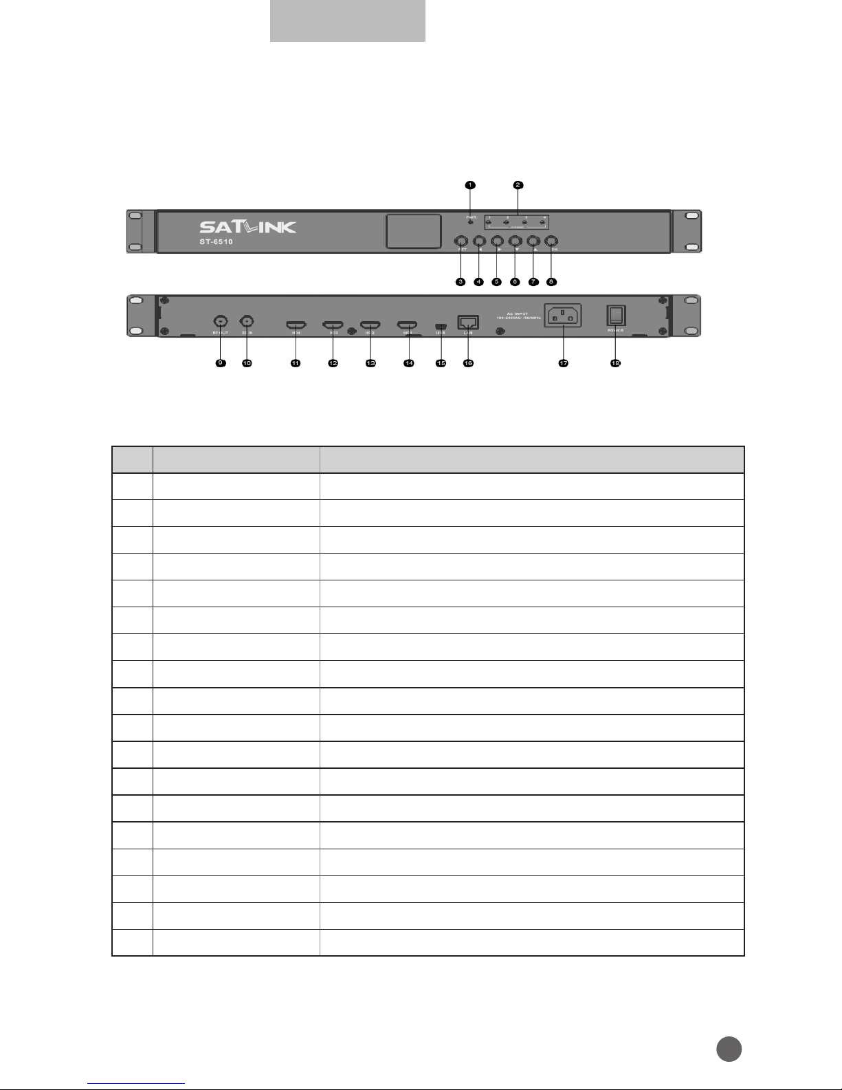
1.3 PRODUCT OVERVIEW & ILLUSTRATION
NO Description FUNCTION
1 PWR Power indicator light
2 Channel HD channel indicator light
3 RETURN Return to superior menu and save settings
4
A
Switch settings in menu or cursor left
5
B
Switch settings in menu or cursor right
6
Z
Change the frequency point or cursor down
7
Y
Change the frequency point or cursor up
8 OK Confirm the current operation
9 RF OUT RF output port
10 RF IN Terrestrial Digital signal input port
11 HD4 Channel 4 HD signal input port
12 HD3 Channel 3 HD signal input port
13 HD2 Channel 2 HD signal input port
14 HD1 Channel 1 HD signal input port
15 USB Connect to PC for upgrade
16 LAN Modify parameters by network
17 AC INPUT 100~240V alternating current input port
18 POWER Power switch
Page 6

4
2. FEATURES
• Integration of H.264/AVC HD Encoder and DVB-T Modulator in a 19” 1U rack
mount system
• Quad HD video inputs
• Adopt multiple audio formats
• 1 x DVB-T RF out
• Bandwidth: 6/7/8MHz
• Frequency range: 50~860MHz
• Software attenuator
• Support Low Delay
• LCN (Logical Channel Number) support
• Excellent modulation quality
• User friendly configuration interfaces including 1.7-inch LCD with buttons
• Support modifying parameters by network
• Upgrade by PC
Page 7
5
English
3. THE MENU OSD INSTRUCTION
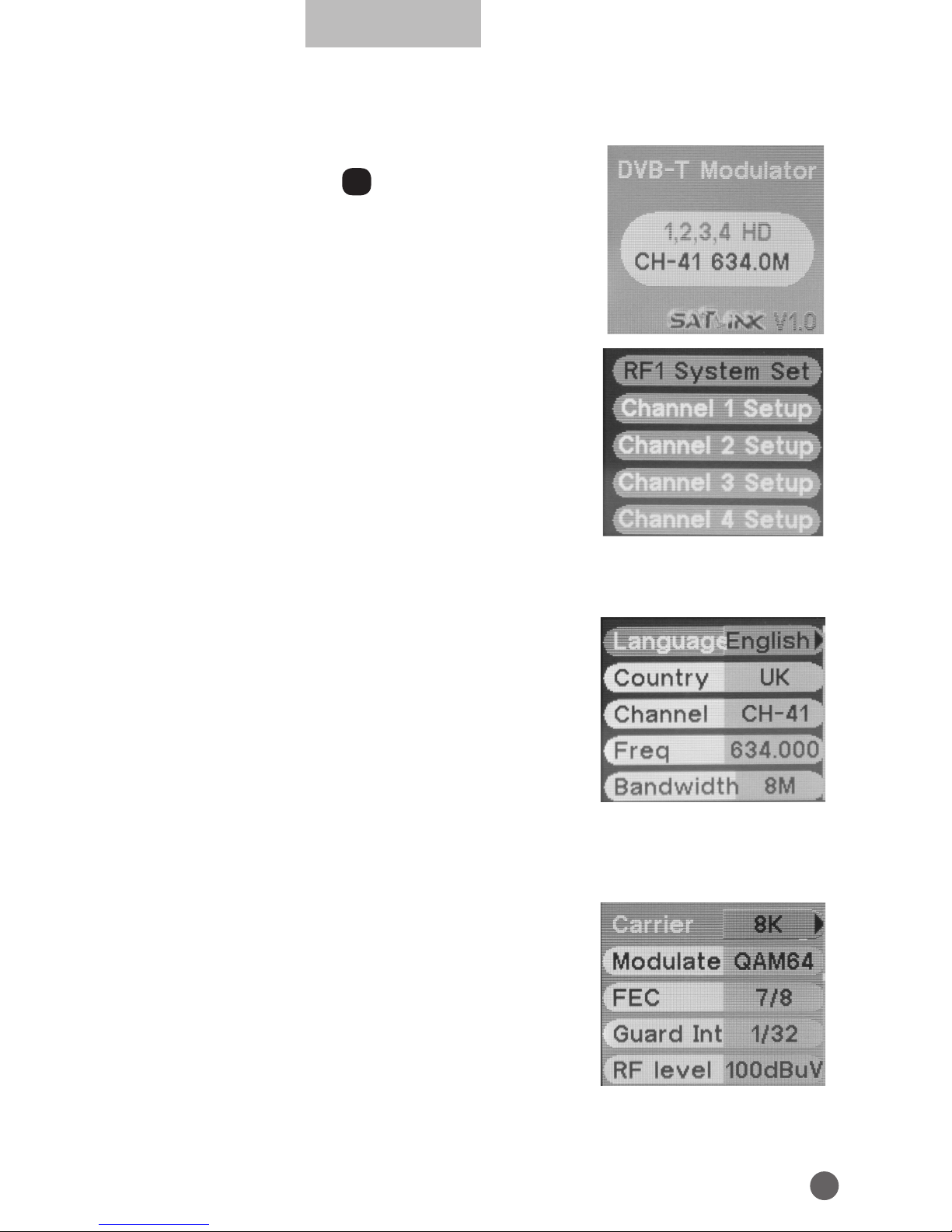
Modulator will initialize to the boot interface after
power on, and press OK into the main menu.
There are 5 options in main menu:
• RF1 System Set
• Channel 1 Setup
• Channel 2 Setup
• Channel 3 Setup
• Channel 4 Setup
3.1 RF1 SYSTEM SET
• Language: press
AB
key to change OSD
language.
• Country: press
AB
key to enter country list, and
use
YZ
key to select a country, then press OK
to confirm.
• Channel: press
AB
key to change the channel
number.
• Freq: frequency setting in range of 50~860MHz, press
AB
key to move
cursor and press
YZ
key to change numbers.
• BandWidth: press
AB
key to select bandwidth of 6/7/8MHz.
• Carrier: carrier setting, press
AB
key to select
2K or 8K.
• Modulate: modulation mode setting, press
AB
key to select QPSK, 16QAM or 64QAM.
• FEC: FEC code rate setting, press
AB
key to
select 1/2, 2/3, 3/4, 5/6 or 7/8.
• Guard Interval: guard interval setting, press
AB
key to select 1/4, 1/8, 1/16 or 1/32.
• RF Level: RF output level setting, press
AB
key to change value in range of
Page 8
6
70~100dBuV.
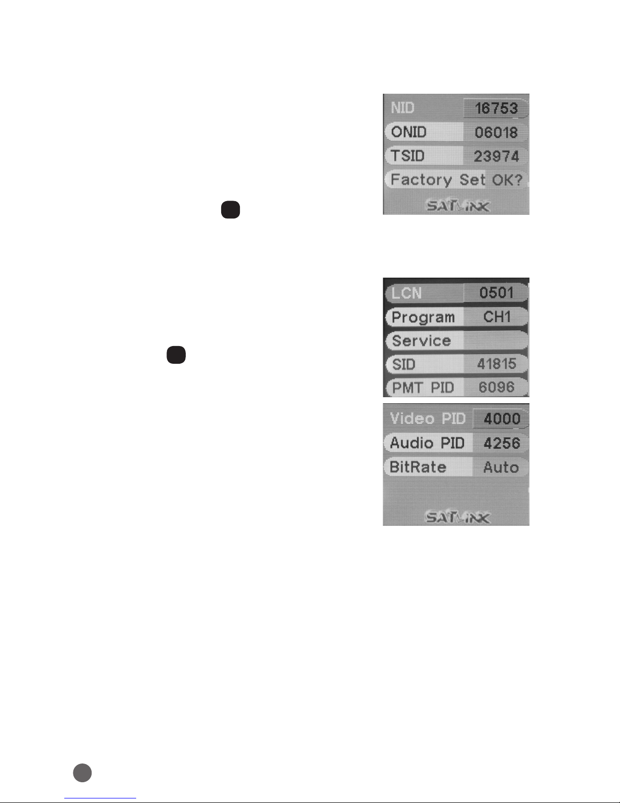
• NID: Network ID can be modified by
YZAB
key.
• ONID: Original Network ID can be modified by
YZAB
key.
• TSID: Transport Stream ID can be modified by
YZAB
key.
• Factory Set: press OK to confirm factory reset.
3.2 CHANNEL 1/2/3/4 SETUP
• LCN: Logic Channel Number can be modified
by
YZAB
key.
• Program: CH1/CH2/CH3/CH4.
• Service: service name can be modified after
pressing OK.
• SID: Service ID can be modified by
YZAB
key.
• PMT PID: Program Map Table PID can be
modified by
YZAB
key.
• Video PID: Video PID can be modified by
YZAB
key.
• Audio PID: Audio PID can be modified by
YZAB
key.
• BitRate: default setting is Auto, or you can
press
AB
key to switch to 2/3/4/5/6M.
Page 9
7
English
4. TECHNICAL SPECIFICATION
INPUT
VIdeo Input
4 x HDMI(HDCP): Type A receptacle
Audio Input
4 x HDMI type A receptacle
Encoding
Video Resolution 1080p @30p/25p
Video Compression H.264/ AVC
Audio Compression MPEG-1 Audio layer II (ISO/IEC 11172-3)
PID Setting PMT/ Video/ Audio/ PCR
PSI NID/ ONID/ P.D.S./ TS ID
LCN At most 4 numbers
Service Name At most 12 characters
GENERAL CHARACTERISTICS
Type 19 inch rack mount
Dimensions 480×180×44mm
Power Supply AC 100~240 V
Power
Consumption
20 W
Operation
Temperature
0 ~ +45°C
MODULATION
Transmission Mode 8K
Guard Interval 1/32
Code Rate 7/8
Constellation 64QAM
OUTPUT
Standard DVB-T (ETSI EN 300 744)
Frequency Range 50-860 MHz
Output Level 70~100 dBuV
Bandwidth 6, 7, 8 MHz
MER >36 dB
Connector Type ‘F’ Female
CONTROL
Local operation LCD panel, control buttons
User Interface 10/ 100M IP Web Browser
Note: Specifications are subject to change without notice.
Page 10

USER’S MANUAL
 Loading...