

Page 1

ST-5810 / ST-5610 Operation Manual
ST-5810 / ST-5610
Universal TV Signal Level Meter
DVB-C/C2, DVB-S/S2, DVB-T/T2, ISDB-T(b), ATSC 1.0/3.0
Operation Manual
www.satlinkcn.com
www.starlink7.com
Copyright © 2021 SatLink Electronics 1
Page 2

ST-5810 / ST-5610 Operation Manual
Notices
Copyright © 2020 Fujian Satlink Electronics Co., Ltd. All rights reserved.
Copyright © 2020 StarLink LLC. All rights reserved.
No part of this manual may be reproduced in any form or by any means (including electronic storage and retrieval or
translation into a foreign language) without prior agreement and written consent from Satlink Electronics Co., Ltd. as
governed by United States and international copyright laws.
Copyrights & Trademarks
All of the company names and/or brand names and/or product names referred to in this document, in particular, the name
“Satlink”, “ST-5810”,”ST-5610”, its logo and device, are either registered trademarks or trademarks of Satlink Electronics Co.,
Ltd. pending registration in accordance with relevant national laws. All other registered trademarks or trademarks are the
property of their respective owners.
Warranty
The material contained in this document is subject to change without notice. Satlink makes no warranty of any kind with
regard to this material, including, but not limited to, the implied warranties of merchantability and fitness for a particular
purpose. Satlink shall not be liable for errors contained herein or for incidental or consequential damages in connection with
the furnishing, performance, or use of this material. Since some countries or states do not allow limitation of the term of an
implied warranty, or exclusion or limitation of incidental or consequential damages, the limitations and exclusions of this
warranty may not apply to every buyer. If any provision of this Warranty is held invalid or unenforceable by a court of
competent jurisdiction, such holding will not affect the validity or enforceability of any other provision.
Assistance
Product maintenance agreements and other customer assistance agreements are available for Satlink products.
For sales assistance or technical support, contact Satlink Sales and/or Service office.
Warning
Using the supplied equipment in a manner not specified by Satlink may impair the protection provided by the equipment.
End of Life Recycling and Disposal Information
Do not dispose of Waste Electrical and Electronic Equipment (WEEE) as unsorted municipal waste. For proper disposal return
the product to Satlink. Please contact our local offices or server centers for information on how to arrange the return and
recycling of any of our products.
EC Directive on Waste Electrical and Electronic Equipment (WEEE)
The Waste Electrical and Electronic Equipment Directive aims to minimize the impact of the disposal of electrical and
electronic equipment on the environment. It encourages and sets criteria for the collection, treatment, recycling, recovery,
and disposal of waste electrical and electronic equipment.
Copyright © 2021 SatLink Electronics 2
Page 3

ST-5810 / ST-5610 Operation Manual
Table of Contents
1. INTRODUCTION ..................................................................................................................................................................................... 5
1.1 Overview and Functions ................................................................................................................................................................ 5
1.2 Important Safeguards and Precautions ...................................................................................................................................... 5
1.3 Convention Used In This Manual................................................................................................................................................... 5
1.4 Copyright ........................................................................................................................................................................................ 6
1.5 Safety Notices ................................................................................................................................................................................. 6
1.6 Warranty .......................................................................................................................................................................................... 6
1.6.1 Limitation of Warranty ............................................................................................................................................................. 7
1.7 Statement of FCC Compliance .................................................................................................................................................... 7
1.8 Glossary of Acronyms .................................................................................................................................................................... 7
2. WALKTHROUGH .................................................................................................................................................................................... 10
2.1 Identify Components ...................................................................................................................................................................... 10
2.2 Navigating Functions ...................................................................................................................................................................... 11
2.3 Display Screen .............................................................................................................................................................................. 12
2.3.1 Home ...................................................................................................................................................................................... 12
2.3.2 Measurement Screen ........................................................................................................................................................... 12
2.3.3 Configuration Screen ............................................................................................................................................................ 13
2.4 Battery Charging .......................................................................................................................................................................... 13
2.5 Package........................................................................................................................................................................................ 13
3. OVERVIEW ........................................................................................................................................................................................... 14
3.1 Key Ffeatures ................................................................................................................................................................................ 14
3.2 System Setup ................................................................................................................................................................................ 16
3.3 About ............................................................................................................................................................................................. 16
4. MEASUREMENT .................................................................................................................................................................................... 17
4.1 Channel Plan ................................................................................................................................................................................ 17
4.1.1 Network (Profile) Editor ......................................................................................................................................................... 17
4.1.2 Channel Plan Editor .............................................................................................................................................................. 19
Copyright © 2021 SatLink Electronics 3
Page 4

ST-5810 / ST-5610 Operation Manual
4.2 Channel Discovery ....................................................................................................................................................................... 20
4.3 Limit Configuration ....................................................................................................................................................................... 21
4.4 Power Level ................................................................................................................................................................................... 22
4.5 Constellation ................................................................................................................................................................................. 23
4.6 Spectrum Analysis ........................................................................................................................................................................ 24
4.6.1 How To Identify Channel Frequency From Spectrum Trace ............................................................................................. 26
4.7 Signal-Over-Noise Ratio (SNR) Monitoring ................................................................................................................................. 27
4.8 Multi-Channel Scan ..................................................................................................................................................................... 28
4.9 Tilt ................................................................................................................................................................................................... 29
4.10 Report List .................................................................................................................................................................................... 30
5 DVB-S/S2 SPECIFIC ............................................................................................................................................................................... 31
5.1 Measurement ............................................................................................................................................................................... 31
5.2 Multi-Transponder Scan ............................................................................................................................................................... 32
5.3 DiSEqC Switch Test ....................................................................................................................................................................... 33
5.4 Rotor Control ................................................................................................................................................................................ 34
5.5 Angle Calculation ........................................................................................................................................................................ 35
5.6 Limit Configuration ....................................................................................................................................................................... 36
5.7 Satellite and Transponder Editor ................................................................................................................................................. 37
6. REFERENCE .......................................................................................................................................................................................... 38
6.1 Customer ServIce ......................................................................................................................................................................... 38
6.2 Testing and Calibration Statement ............................................................................................................................................ 38
6.3 Express Limited Warranty ............................................................................................................................................................. 38
6.4 Safty Instructions ........................................................................................................................................................................... 39
6.5 Coax Cable .................................................................................................................................................................................. 39
6.6 FCC Class B Equipment ............................................................................................................................................................... 39
6.7 Declaration of Conformity for Products Marked With the FCC Logo – USA Only .................................................................. 39
6.8 Declaration of CE Conformity for EU .......................................................................................................................................... 39
Copyright © 2021 SatLink Electronics 4
Page 5

ST-5810 / ST-5610 Operation Manual
1. INTRODUCTION
1.1 OVERVIEW AND FUNCTIONS
ST-5810 is the new signal level meter presented by SatLink. With cutting edge technologies and advanced platform, ST-5810
supports universal digital TV standards to analyze signals in real time, including spectrum analysis, demodulation parameters,
and constellation to provide you with optimal features for reduced cost. The device is the ideal signal level meter for
broadcasting TV installations. It is durable, has many features, and is light weighted, rugged, simple to use in a wide range of
conditions with one hand.
Automatic channel discovery and user defined channel plans may be stored and loaded to perform complete test of all
channels in the selected channel plan to specific limits.
Patented real time spectrum analysis methodology is used to provide precise spectrum scan and analysis functions over
Satellite TV, Terrestrial TV, Cable TV and Over-The-Air TV signals in all frequency range. dCSS MDU and DisEqc applications
are also supported.
ST-5810 equips with capacitive touch panel and high-resolution LCD screen. Together with friendly and intuitive graphical
user interface, the learning curve of operating ST-5810 is minimal.
With its low-cost and high-performance feature set, ST-5810 can be used to measure and validate all kinds of TV service
deployed by service providers with following key features.
Highlights
Compatible with all digital TV standards - DVB-S/S2, DVB-T/T2, ISDB-T/S/C, ATSC 1.0/3.0, DVB-C/C2, J.83 A/B/C
Fast and reliable signal data processing
Patented dual-frequency spectrum scan and capture module
Rich spectrum analysis functions
Specific details of measurement statistics for channel quality
Constellation for all kinds of digital TV signals
Antenna/LNB angle calculation
Satellite motor DisEqc and dCSS MDU application support
dCSS MDU support
LNB power compensation
Audible tone to reflect signal strength
High-resolution LCD display
Capacitive touch panel
Friendly and intuitive graphical user interface
High-capacity lithium battery for long operation and storage hours
USB interface for firmware upgrade and file transfer
Built-in parameters for global satellites and transmitters
1.2 IMPORTANT SAFEGUARDS AND PRECAUTIONS
Utmost care has been taken in the manufacture of the ST-5810. Please keep the following instructions in mind while using the
tester.
Please keep the tester away from fire, extremely hot areas, water or moisture of any kind.
Do not service your tester by yourself.
Opening the tester housing will void the warranty.
Always follow the instructions to configure and maintain.
1.3 CONVENTION USED IN THIS MANUAL
This manual has several standard conventions for presenting information.
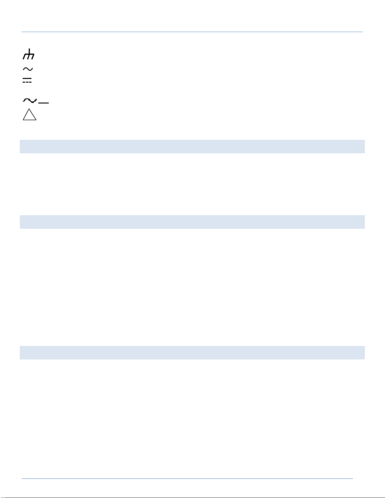
Dangerous voltage
Protective ground
Copyright © 2021 SatLink Electronics 5
Page 6
ST-5810 / ST-5610 Operation Manual
Frame or chassis ground
Alternating current
Direct current
Alternating or direct current
Caution
1.4 COPYRIGHT
All rights reserved. Reproduction, adaptation, or translation without prior written permission is prohibited, except as allowed
under the copyright laws. The information contained in this document is subject to change without notice.
SatLink and StarLink makes no warranty of any kind with regard to this material, including, but not limited to, the implied
warranties of merchantability and fitness for a particular purpose.
SatLink shall not be liable for errors contained herein or for incidental or consequential damage in connection with the
furnishing, performance, or use of this material.
1.5 SAFETY NOTICES
Observe the following safety precautions whenever you operate any SatLink instrument. Failure to comply with these and
other specific warnings and cautions is violation of SatLink’s safety standards of design, manufacturing, and intended use of
the measurement device. SatLink assumes no liability for the operators’ failure to comply with these precautions.
Do not use this product if it shows visible damage, fails to perform, has been stored in unfavorable conditions, or has been
subject to severe transportation stresses. Make the product inoperative and secure it against any unintended operation.
Contact your SatLink representative for assistance.
Do not operate the instrument in the presence of flammable gases or fumes.
To avoid possibility of severe injury or death, observe the following precautions when using any SatLink equipment:
Do not remove system cover, and do not preform electrical tests if there are signs of shipping damage to the outer
enclosure.
When connecting test cables to a line, do not touch the cable’s metal contact points, or allow the cable leads to
touch each other.
Use only the supplied power cords and connect only to a properly grounded wall outlet. Do not use extension cords
that do not have a protective ground conductor.
1.6 WARRANTY
This SatLink product is warranted against defects in material and workmanship for a period of 24 months from date of
shipment. During the warranty period, SatLink will, at its option, either repair or replace products which prove to be
defective.
For warranty service or repair, this product must be returned to an authorized service center designated by SatLink. The
buyer shall prepay shipping charges to SatLink or the service center and SatLink or the service center shall pay the shipping
charges to return the product. However, the buyer is responsible for all duties and taxes to receive the product after service
or repair.
SatLink warrants that its software and firmware are designated by SatLink for use with SatLink equipment, and will execute its
programming instructions when properly installed on that instrument. SatLink does not warrant that the operation of the
instrument, software, or firmware will be uninterrupted or error-free but strive to insure the best operating condition as per
specifications and datasheets.
Copyright © 2021 SatLink Electronics 6
Page 7

AAC
Advanced Audio Coding
AC-3
Dolby AC
-
3 audio coding
BPCP
Bidirectional Coded Picture
CAT
Conditional Access Table
CCIR
International Radio Consultative Committee
CPE
Customer Premise
Equipment
Composite Video Broadcast Signal Color Video Blanking and Sync
DIT
Discontinuity Information Table
ST-5810 / ST-5610 Operation Manual
1.6.1 LIMITATION OF WARRANTY
Unauthorized repair or update, physical damage or improper operational voltage (at the power supply or RF input) will void
this warranty. The main lithium battery is covered for a period of 1 year.
The foregoing warranty shall not apply to defects resulting from improper or inadequate use or maintenance by buyer.
Buyer-supplied software or interfacing, unauthorized modifications or misuse, operation outside of the environment
specifications for the product.
No other warranty is expressed or implied. SatLink specifically disclaims the limited warranty of merchantability and fitness for
a particular purpose.
1.7 STATEMENT OF FCC COMPLIANCE
The ST-5810 complies with Part 15 of the FCC Rules. Operation is subject to the following two conditions: (1) this device may not
cause harmful interference, and (2) this device must accept any interference
undesired operation.
This equipment has been tested and found to comply with the limits for a Class A digital device, pursuant to Part 15 of the FCC
Rules. These limits are designed to provide reasonable protection against harmful
in a commercial environment.
This equipment uses, and can radiate radio frequency energy and, if not installed and used in accordance with the instruction
manual, may cause harmful interference to radio communications.
In some situations, operation of this equipment in a residential area may cause harmful interference, in which case the user will be
required to correct the interference at his or her own expense.
received, including interference that may cause
interference when the equipment is operated
1.8 GLOSSARY OF ACRONYMS
ACPR
AEC
AES
ATDMA
ATSC
AVG Average
BAT
BER
CCN
CRC
CSO
CTB
CM
CLDI
CLGI
CMTS
CVBS
CW
DAVIC
DCT
DFT
DG
DHCP
Adjacent Channel Power Ratio
Audio Engineering Society
Advanced Encryption Standard
Advanced Time Division Multiple Access
Advanced Television Systems Committee
Bouquet Association Table
Bit Error Rate
Carrier-to-Composite Noise Ratio
Cyclic Redundancy Check
Composite Second Order Beat
Composite Triple Beat
Cable Modem
Chrominance-Luminance Delay Inequality
Chrominance-Luminance Gain Inequality
Cable Modem Terminal System
Composite Video, Blanking, Synchronization
Composite Video Bar Signal
Continuous Wave
Digital Audio Video Council
Discrete Cosine Transform
Discrete Fourier Transform
Differential Gain
Dynamic Host Configuration Protocol
Copyright © 2021 SatLink Electronics 7
Page 8

DOM
Depth of Modulation
EBU
European Broadcasting Union
ECM
Entitlement Control Message
EIA
Electronic
Industries Association
EVS
Error Vector Spectrum
ES
Errored second
FCC
Federal Communications Commission
GOP
Group of Pictures
GPS
Global Positioning System
IRD
Integrated Receiver Decoder
ISO
International
Organization for Standardization
ITU
International Telecommunications Union
MPEG
Moving Pictures Expert Group
MSB
Most Significant Bit
OPM
Optical Power Meter
PAL
Phase Alternate Line
PAT
Program Association Table
ST-5810 / ST-5610 Operation Manual
DNS
DOCSIS
DP
DTS
DVB
DVB-C
EAP
EIT
EMM
eMTA
EPG
ES
ETSI
ETT
EVM
FDD
FEC
FFT
FIP
FM
FSK
FTP
GCR
Domain Name System
Data-Over-Cable Service Interface Specifications
Differential Phase
Decoding Time Stamp
Digital Video Broadcasting
Digital Video Broadcasting-Cable
Extensible Authentication Protocol
Event Information Table
Entitlement Management Message
Embedded multimedia terminal adapter
Electronic Program Guide
Elementary Stream
European Telecommunications Standards Institute
Extended Text Table
Error Vector Magnitude
Frequency division duplex
Forward Error Correction
Fast Fourier Transform
Fiber Inspection Probe
Frequency Modulation
Frequency-Shift Keying
File Transfer Protocol
Ghost Cancellation Reference
HD
HFC
ICP
ICR
IEC
IEEE
IMD
IP
JCTEA
LAN
LSB
LTE
MAC
MER
MGT
MPE
MSD
NCTA
NEG
NIT
NTSC
NVOD
OFDM
OFDMA
High Definition (video)
Hybrid Fiber-Coaxial
Intra Coded Picture
In Channel Frequency Response
International Electrotechnical Commission
Institute of Electrical & Electronics Engineers
Intermodulation Distortion
Internet Protocol
Japan Cable Television Engineering Association
Local Area Network
Least Significant Bit
Long term evolution
Media Access Control layer
Modulation Error Ratio
Master Guide Table
Multi-Protocol Encapsulation
Minimum Signal Duration
National Cable Television Association
Negative peak
Network Information Table
National Television Standards Committee
Near Video On Demand
Orthogonal frequency division multiplexing
Orthogonal frequency division multiple access
Copyright © 2021 SatLink Electronics 8
Page 9

PCP
Predictive Coded Picture
PING
Packet Internet Groper
PPPoE
Point to Point Protocol over Ethernet
PSI
Program Specific Information
RSSI
Received signal strength indicator
RST
Running Status Table
RF
Radio Frequency
SECAM
Sequential Color and Memory Sequential Couleur avec Memoire
SI
Service Information
STT
System Time Table
TDMA
Time Division Multiple Access
TDD
Time division duplex
UCD
Upstream Channel Descriptor
UE
User equipment
WiFi
Wireless Fidelity
WEP
Wired Equivalent Privacy
WPA-PSK
Wi-Fi Protected Access
-
Pre-shared key
ST-5810 / ST-5610 Operation Manual
PCR
PDCCH
PES
PID
PMT
POS
POI
PSIP
PSK
PTS
QAM
QPSK
RMS
RBW
RRT
SAM
SES
SCDMA
SC-FDMA
SCTE
SD
SDT
SES
Program Clock Reference
Physical downlink control channel
Packetized Elementary Stream
Packet Identifier
Program Map Table
Positive Peak
Probability Of Intercept
Program and System Information Protocol
Phase Shift Key
Presentation Time Stamp
Quadrature Amplitude Modulation
Quadrature phase shift keying
Root Mean Square
Resolution Band Width
Ratings Text Table
Sample detector
Severely errored second
Synchronous Code Division Multiple Access
Single carrier frequency division multiple access
Society of Cable Telecommunication Engineers
Standard Definition (video)
Service Description Table
Severely errored second
SIT
SMPTE
SNR
SSID
ST
STB Set Top Box
STC
STD
TDT
TFTP
TKIP
TOD Time Of Day
TOT
TS
TSDT
TVCT
UTC
VBW
VCT
VFL
V/A
VITS
VoIP
VSB
Selection Information Table
Society of Motion Picture and Television Engineers
Signal-to-Noise Ratio
Service Set Identifier
Stuffing Table
System Time Clock
System Target Decoder
Time and Date Table
Trivial File Transfer Protocol
Temporal Key Integrity Protocol
Time Offset Table
Transport Stream
Transport Stream Description Table
Terrestrial Virtual Channel Table
Coordinated Universal Time
Video Band Width
Virtual Channel Table
Visual Fault Locator
Video to Audio carrier level ratio
Vertical Interval Test Signal
Voice over Internet Protocol
Vestigial Sideband Modulation
Copyright © 2021 SatLink Electronics 9
Page 10
ST-5810 / ST-5610 Operation Manual
2. WALKT H R O U G H
2.1 IDENTIFY CO M PONENTS
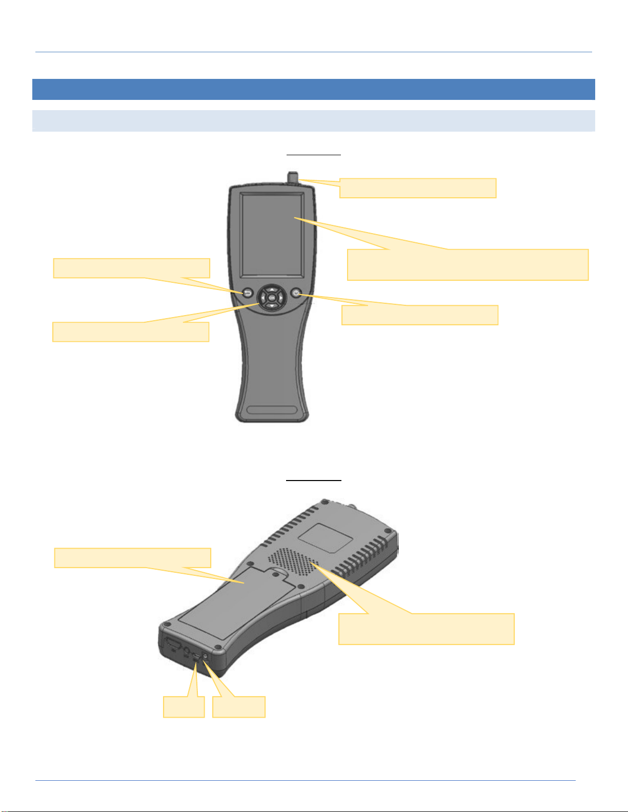
Navigation keys & OK button
Back key
Front Panel
RF F connector for signal input
3.95“, 480 x 320, 16-bit color LCD with bright backlight
capacitive touch panel 55.68 x 83.52mm
Power On/Off
Back Panel
Battery chamber
Sound and signal alarm/lock
USB-A DC 12V
Copyright © 2021 SatLink Electronics 10
Speaker
Page 11

ST-5810 / ST-5610 Operation Manual
2.2 NAVIGATING F U NCTIONS
Several methods are used to navigate the ST-5810 functions, including context sensitive Home button and alphanumerical
soft keypad as shown below.
Backspace
Numerical soft keypad
Parameter description
Return to Home
Delete
Collapse soft keypad
Enter
Function/Command button
Editable field
Measurement display area
Edit button
Drop down selection
Alphabetical soft keypad
Toggle to numerical soft keypad
Copyright © 2021 SatLink Electronics 11
Page 12

ST-5810 / ST-5610 Operation Manual
2.3 DISPLAY SCREEN
ST-5810 equips with 3.95” high-resolution LCD display and capacitive touch panel to enrich excellent user experience. Its
smart-phone UI style makes the operation friendly and intuitive without learning curve.
2.3.1 HOME
Title bar
TV (modulation) standard
Battery (charging) status
Functional icons
2.3.2 MEASUREMENT SCREEN
Network profile selected
Applicable commands
Measurement display area
Drop down for selection
Detail measurement values
Copyright © 2021 SatLink Electronics 12
Page 13

ST-5810 / ST-5610 Operation Manual
Editable fields with popup soft
2.3.3 CONFIGURATION SCREEN
Parameter description
Parameter status
2.4 BATTERY CHARGING
The ST-5810 has built-in 7.4V/2000mAh Li-Ion battery installed. When fully charged, it can be used for up to 8 hours. When the
battery capacity drops below 10%, the battery symbol shows red at the top of the display screen. If the charge drops below
6.4V, the ST-5810 shuts off automatically to protect the battery. The ST-5810 cannot be turned on again until it’s recharged.
To charge the ST-5810 battery, connect the battery charger to the charge socket on the bottom of ST-5810 (see chapter 2,
section 2.: Identify Components) and plug the charger into an AC outlet. The battery must be charged with the SatLink
charge cube provided with the ST-5810. Using other charge cube may damage the battery.
A full charge will be achieved in less than three hours. The charging status may be observed by tapping the Power button
or turn the unit on while the charger is connected. The charging progress will be seen with a charging bar and an
approximate percentage of charge. The ST-5810 can be operated while the batter
2.5 PACKAGE
The ST-5810 comes with the followings:
ST-5810 Universal Signal Level Meter with protective rubber bumper
7.4V/2000mAh Li-Ion battery (installed)
AC to DC power adapter and battery charger 100-240VAC 50/60Hz
USB-C to USB-A data cable
Operation manual
Copyright © 2021 SatLink Electronics 13
Page 14

ST-5810 / ST-5610 Operation Manual
3. OVERVIEW
ST-5810 supports digital TV analysis and measurement of all broadcast TV standards – DVB-S/S2, DVB-T/T2, ISDB-T/C/S, DVBC/C2, J.83A/B, and ATSC 1.0/3.0 over Satellite TV, Terrestrial TV, Cable TV and Over-the-Air Broadcasting TV in full frequency
range. ATSC 1.0/3.0 features are only available on ST-5810.
Before using the tester, dedicated digital TV standard needs to be selected by dropping down the selection box form the
top of the display screen as shown below. Depending on the regional requirement, your tester may not be configured to list
all digital TV standards for selection. Contact your local sales channel for optional standards to be enabled in case required
settings are missing.
3.1 KEY FFEATURES
Level Measurement
When tuned to a single channel, the ST-5810 displays bar graphs for the video and audio carriers or power of a digital
channel. It also shows numeric readouts of the carrier amplitudes and V/A difference or digital power.
QAM Measurement
The ST-5810 is capable of measuring the channel power of QAM, QPSK, and COFDM signals. This function also enables the
measurement of pre- and post-BER and MER for QAM modulated signals. The QAM measurement mode also features a single
channel spectrum display and an optional Constellation diagram is available to enable users to find errors more quickly.
BER Measurement
The BER Measurement function displays the ratio of corrupted bits to total bits in the QAM signal. The analyzer dwells on the
selected channel, counting good bits and watching for individual corrupted bits. The BER graph shows errored bits as vertical
lines that expand horizontally across the display with advancing time.
Tilt Measurement
The Tilt Measurement function displays a graph showing the amplitudes of up to twelve user- selected video carriers. This display
also shows the calculated difference in amplitude (tilt) between the highest and lowest channels in the user-selected group. The
ST-5810 can also display a numeric list that shows the amplitudes of the carriers in the group.
Multi-Channel Scan
The Channel Scan Measurement function displays the full span of video and audio carriers in the selected user channel plan. This
mode is useful to make a quick check of your system's overall flatness and amplitude.
Amplitude limits can be imposed on the display and the frequency marker can be used to isolate any suspect channel that
appears in the display.
Copyright © 2021 SatLink Electronics 14
Page 15

ST-5810 / ST-5610 Operation Manual
Spectrum Analysis
The ST-5810 can also provide a spectral display of the selected channel including intermodulation products or other undesired
signals that may be present.
For a digital channel, this measurement shows the actual shape of the modulation "haystack" to determine if there are any
problems with the digital transmission system. This feature provides you with a powerful tool for checking in-channel flatness or
mismatches that might affect digital transmission quality.
Limit Measurement
The ST-5810 can perform a complete test of all analog channels in the selected user channel plan to specified limits. All
channels are listed with Pass or Fail results, and the user may select any channel to review its individual test results. In addition,
results for the entire channel plan, such as Maximum ∆ Video and Maximum ∆ Adjacent Channel, are seen on the test-result display.
SNR Measurement
The ST-5810 can perform measurement of the Signal-to-Noise Ratio (or SNR) of Analog (NTSC, PAL) non-scrambled channels.
Measurement Report Saving and Viewing
Power Level, Tilt, Spectrum, Channel Scan, Limit measurements can be saved and transferred through the USB-C to local
computer. The ST-5810 has the capability to store the amplitudes of all video and audio carriers. These data records can be
captured in memory and later recalled or uploaded.
Copyright © 2021 SatLink Electronics 15
Page 16

ST-5810 / ST-5610 Operation Manual
Restore factory default
Notes of testing point
3.2 SYSTEM SETUP
Language of graphical user
interface
Loud speaker volume
Enter the optional Longitude,
Latitude, Address and additional
Shutdown timer to save
(battery) power
Power measurement unit
3.3 ABOUT
The About command will show firmware version and the serial number of the instrument.
Copyright © 2021 SatLink Electronics 16
Page 17

ST-5810 / ST-5610 Operation Manual
4. MEASUREMENT
Different measurement functions can be available for different TV standards. Following sections cover most of the general
measurement functions. Special notes are added in case the measurement function described doesn’t apply to specific TV
standard.
4.1 CHANNEL PLAN
TV channel lineup can be discovered or composed and saved on the unit for easily traversing different channels in different
measurement modes without entering channel frequency. If channel number and channel frequency are known to the
user, channel plan can be composed by using Channel Editor function described below. Otherwise, Channel Discovery
function can automatically discover available TV channels from the input signal.
4.1.1 NETWORK (PROFILE) EDITOR
All information of channel lineup is grouped and saved under Network (profile). Network profile can be selected and
loaded before the measurement gets started. Multiple Network profiles can be saved with different channel lineup
information, but only one Network profile can be selected at once for measurement purpose. Depending on the TV signal
type enabled, a default Network profile might be available for selection. If default Network profile is unavailable, it’s easy to
create one by using the Add button.
OK button
Alphanumerical soft keypad
Network profile name
Edit Network profile Name
Copyright © 2021 SatLink Electronics 17
Page 18

ST-5810 / ST-5610 Operation Manual
List
of existing Network profiles
Delete, Edit, Add Network profile
Network profile list
Selected Network profile name
Manage Network profile
Cancel
Copyright © 2021 SatLink Electronics 18
Network profile name
OK
Add Network profile
Page 19

ST-5810 / ST-5610 Operation Manual
4.1.2 CHANNEL PLAN EDITOR
Channel information can be manually edited from or added to the existing Network profile.
Dropdown of Network profile for
selection
Channel list with selected
channel highlighted
Information of selected channel
Command buttons to Delete, Edit
or Add channel
Channel information to add
Starting channel frequency
Channel bandwidth
Starting channel number
Channel count to add
Add single channel
Add multiple channels
Note: consecutive multiple
channels are added in
step of bandwidth (6MHz,
7MHz, or 8MHz)
Channel frequency
Symbol rate
Channel number
Copyright © 2021 SatLink Electronics 19
Page 20

Depending on the modulation
ST-5810 / ST-5610 Operation Manual
4.2 CHANNEL DISCOVERY
TV channel lineup can be discovered and saved by ST-5810 for easily traversing different channels in different measurement
modes without entering channel frequency. Every existing analog and digital channel can be detected in real time to
determine the overall frequency response of the signal. To discover channels available on the RF signal received, enter
following parameters before hitting Start button:
List of channels discovered
Dropdown of Network profile for
selection
Discovered channel count
Channel discovery progress bar
Save channel list to current
Network profile
Start/Stop button of channel
standard, (channel) bandwidth
can be 6000Hz (6MHz ATSC/J.93B),
7000Hz (7MHz DVB-C J.83A) or
8000Hz (8MHz DVB-C J.83A, DVB-S,
Channel discovery frequency
range
the selected Network profile.
Copyright © 2021 SatLink Electronics 20
A message box will confirm the number of new channels discovered and saved to
Page 21

ST-5810 / ST-5610 Operation Manual
4.3 LIMIT CONFIGURATION
Limit is the threshold of measurement values to be justified for pass and fail condition. Limit configuration allows user to
enable, disable and change specific threshold values for measurement condition justification. A Pass or Fail status is
displayed during real time or static measurement according to limit settings.
Limit category
Limit description
TV standard enabled
Limit status: Enabled with check
mark; tap to toggle
Limit/Threshold value
Copyright © 2021 SatLink Electronics 21
Page 22
ST-5810 / ST-5610 Operation Manual
4.4 POWER LEVEL
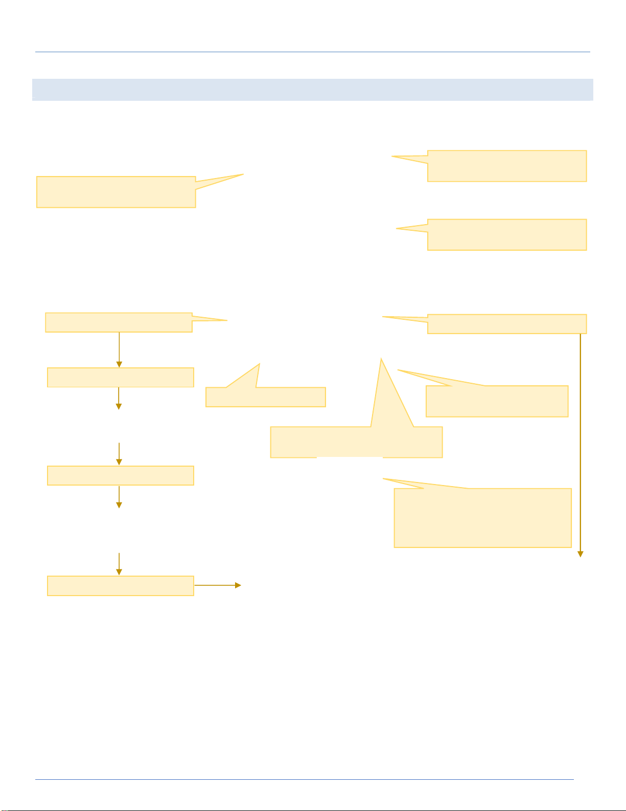
Power level measurement of
selected channel/frequency
Power level of selected
channel/frequency
Other measurement values
(SNR, MER, BER ….)
Selected View Mode
View Mode A
Network profile selection
Drop down to list channels of current
Network profile for selection
View Mode B
measurement; frequency is reflected by
View Mode C
Save measurement report
Change frequency manually
for power level measurement
Scroll up/down by arrow keys ▲▼to
select channel for power level
selected channel (number)
Copyright © 2021 SatLink Electronics 22
Page 23
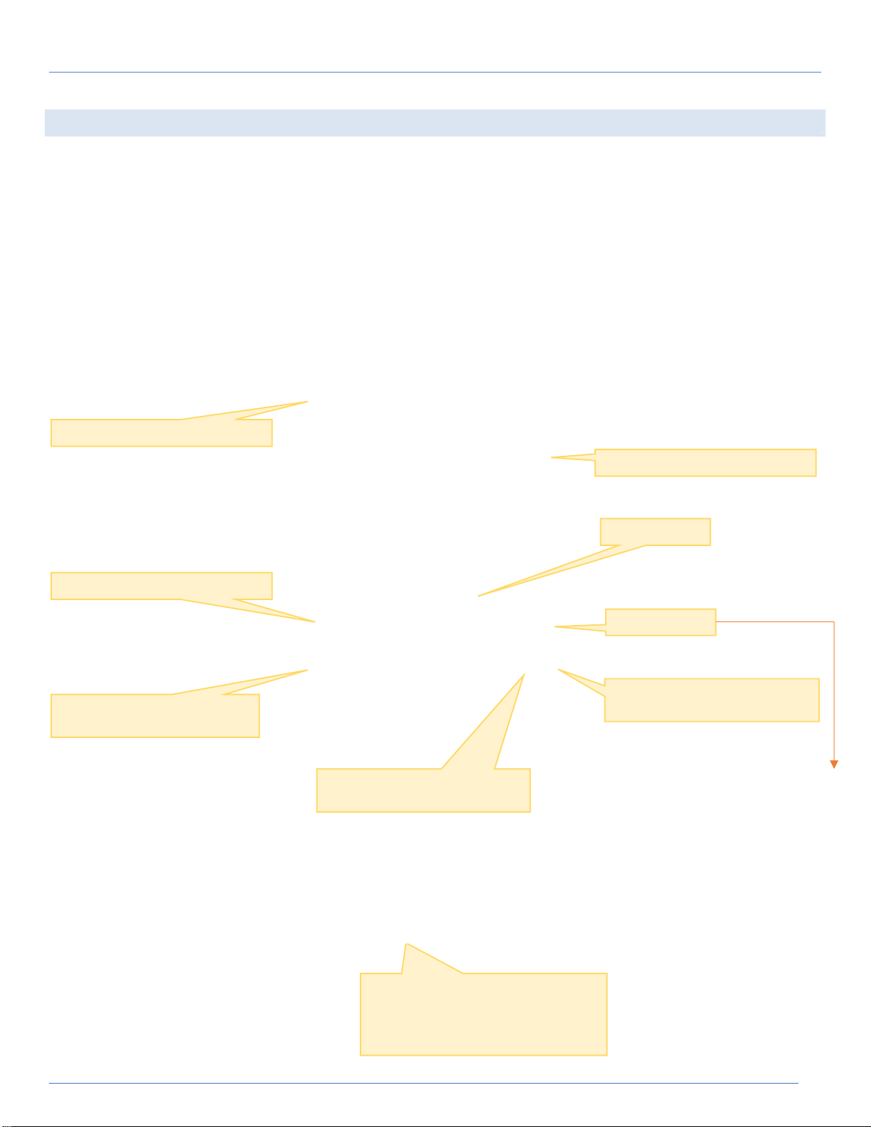
Tap to select
zoom
in quadrant
current Network profile for
Power
level
Zoom
In /
Out
ST-5810 / ST-5610 Operation Manual
4.5 CONSTELLATION
Quadrature Amplitude Modulation, QAM is a form of modulation that is a combination of phase modulation and amplitude
modulation. The QAM scheme represents bits as points in a quadrant grid know as a constellation diagram. Constellation
diagrams are used to graphically represent the quality and distortion of a digital signal. In practice, there is always a
combination of modulation errors that may be difficult to separate and identify, as such, it is recommended to evaluate the
measured constellation diagrams using mathematical and statistically methods.
Modulation type
Dropdown of Network profile for
selection
Constellation diagram
Change frequency manually for
constellation diagram
Copyright © 2021 SatLink Electronics 23
Drop down to list channels of
Scroll up/down by arrow keys ▲▼to
select channel for power level
measurement; frequency is reflected by
selected channel (number)
Page 24
current Network profile for
oversaturation.
ST-5810 / ST-5610 Operation Manual
4.6 SPECTRUM ANALYSIS
A spectrum analysis measures the magnitude of an input signal versus frequency within the full frequency range of the
instrument. The primary use is to measure the power of the spectrum of known and unknown signals/channels. In addition to
display the frequency spectrum of the target channels by utilizing the strong point of wide span, a real-time spectrum
analysis can help with most modern RF measurement challenges, like: discovery of rare, short deration events; seeing weak
signals masked by stronger ones; observing signals masked by noise, finding and analyzing transient and dynamic signals;
capturing burst transmissions, glitches, switching transients…etc.
Multi-touch operations can be used
Spectrum Trace
to zoom in/out, scroll
left/right/up/down and pan over
the spectrum trace
Frequency Range and Span
Dropdown of Network profile for
selection
Frequency (range) settings
Amplitude (range) settings
Marker settings
Trace settings
Change frequency manually for
power level measurement
Drop down to list channels of
Pause trace measurement
Copyright © 2021 SatLink Electronics 24
Frequency span selection, including Full Band
Amplitude settings
Reference: -80 to 0 dBm
dB/Div: +2 to 20 dB
Attenuator: 0 to 40 dB in 5 dB step
Unit: dBm/dBuV
Save spectrum analysis report
Go back to previous menu
For better measurement result,
the input signal is better
attenuated to be lower than
67dBuV to avoid component
Page 25

average, better the filtering effect for glitches or burst noise.
Marker A
Marker B
ST-5810 / ST-5610 Operation Manual
Marker Measurement Marker On/Off
Max Hold, Min Hold and Average (1 to 20) settings
Note: Average 1 means real time spectrum. Greater the
Copyright © 2021 SatLink Electronics 25
Run/Pause trace
measurement
Save trace
measurement report
Page 26

ST-5810 / ST-5610 Operation Manual
4.6.1 HOW TO IDENTIFY CHANNEL FREQUENCY FROM SPECTRUM TRACE
The center frequency of TV channel can also be identified by following steps below
Identify the spike of TV channel from the spectrum trace
Zoom in to the area and set the frequency span to be 50MHz
Enable a Marker (either A or B) and move the marker to the center of the spike
Read the frequency of marker position as the center frequency of specific TV channel
Copyright © 2021 SatLink Electronics 26
Page 27

current Network profile for
ST-5810 / ST-5610 Operation Manual
4.7 SIGNAL-OVER-NOISE RATIO (SNR) MONITORING
Signal over Noise Ratio monitoring records the history of SNR over time. SNR is defined as the ratio of signal power to the
noise power, often expressed in decibels, to compare the level of a desired signal to the level of background noise. A ratio
higher than 1:1 (greater than 0 dB) indicates more signal than noise.
Current SNR measurement value
Pause SNR monitoring
SNR measurement of current
selected channel/frequency
Dropdown of Network profile for
selection
SNR measurement over time
Drop down to list channels of
Copyright © 2021 SatLink Electronics 27
Sampling speed
Threshold/Limit to trigger alarm
Page 28

ST-5810 / ST-5610 Operation Manual
4.8 MULTI-CHANNEL SCAN
Multi-channel scan performs fast scan on selected channels/frequencies to measure power level, SNR, QAM, MER and BER.
Measurement values are summarized in tabular format.
Multi-channel measurement values
Select channel(s) to scan
Start/Stop multi-channel scan
Save report
Copyright © 2021 SatLink Electronics 28
Page 29
selected channel
Sort channels in ascending /
ST-5810 / ST-5610 Operation Manual
4.9 TILT
The Tilt measurement helps to quickly measure the flatness of a TV system and the gain of the splitters / taps by showing the
power level measurement of all channels in bar chart and tabular formats.
Power level chart
Dropdown for Network
profile selection
Power level table
Warning message if power level
limit is triggered
Tilt scan
Tilt measurement configuration
Summary of power
measurement of
Copyright © 2021 SatLink Electronics 29
Enable/Disable selection
descending order by power level
Page 30

ST-5810 / ST-5610 Operation Manual
4.10 REPORT LIST
The Report List browses the file system stored on the instrument. Measurement report file can be viewed, deleted or
renamed.
Dropdown for file type selection
File list
Copyright © 2021 SatLink Electronics 30
Page 31
ST-5810 / ST-5610 Operation Manual
5 DVB-S/S2 SPECIFIC
There are additional functions available for DVB-S/S2 testing
Motor Test
Angle Calculation
Meanwhile, most DVB-S/S2 configuration and measurement apply to satellite (profile) with transponders (TP) list compared
to network (profile) with TV channel plans of other DVB standards.
5.1 MEASUREMENT
Selected View Mode
View Mode A
View Mode B
Drop down for satellite selection
Save measurement report
Drop down for transponder
selection
View Mode C
Copyright © 2021 SatLink Electronics 31
Page 32

ST-5810 / ST-5610 Operation Manual
5.2 MULTI-TRANSPONDER SCAN
Multiple transponders of selected satellite can be scanned for power level, SNR, modulation type and BER.
Dropdown for Satellite selection
Transponder list of selected Satellite
Measurement values of selected
transponder(s)
Start/Stop multi-transponder
scan
Enable/Disable transponder(s) to
be scanned
Save report
Copyright © 2021 SatLink Electronics 32
Page 33

UB ID and Port selection
ST-5810 / ST-5610 Operation Manual
5.3 DISEQC SWITCH TEST
DiSEqC (Digital Satellite Equipment Control), is a special communication protocol for use between a satellite receiver and a
device such as a multi-dish switch or a small dish antenna rotor.
Single-cable distribution (Unicable) is a satellite TV technology that enables the delivery of broadcast programming to
multiple users over a single coaxial cable, and eliminates the numerous cables required to support consumer electronics
devices.
A digital channel-stacking switch (dCSS) IC is a multiple-input multiple-output device. It typically has N 1.2 GHz inputs that
can be cascaded to additional chips as required (to expand output capacity). These inputs are fed into a large N-pole MThrow switch that outputs to M mixers. Each mixer path then translates only the user requested transponder to a
predetermined fixed frequency within the 950-2150 MHz band. This fixed frequency is unique for each tuner on the single
cable output. Each tuner in the STB always stays at this fixed frequency while the dCSS IC translates the user requested
content down the cable to this exact frequency. This architecture requires no hardware change to the STB design .
Signal Strength Indicator (SSI)
Signal Quality Indicator (SQI)
Switch Type
Dropdown for Satellite selection
Unicable standard selection
Copyright © 2021 SatLink Electronics 33
Drop down for transponder
selection
Editable fields to enter frequency
and pin number
Page 34

ST-5810 / ST-5610 Operation Manual
5.4 ROTOR CONTROL
DiSEqC (Digital Satellite Equipment Control) commands can be issued to control the antenna rotor to switch between more
popular satellites. Universal Satellites Automatic Location System (USALS) protocol can also be selected to issue commands
to control the rotor. DiSEqC 1.3 refers to a receiver which uses USALS in conjunction with the DiSEqC 1.2 protocol.
Signal Strength Indicator (SSI)
Signal Quality Indicator (SQI)
Command protocol
Move step
Drop down for Satellite selection
Movement command
Movement orientation
Apply/Execute
Drop down for transponder
selection
Copyright © 2021 SatLink Electronics 34
Page 35

ST-5810 / ST-5610 Operation Manual
5.5 ANGLE CALCULATION
The angle of satellite dish can be calculated to point to selected satellite.
Drop down for Satellite selection
Dish type or enter offset angle
Angle calculated
Editable fields to enter position of
dish for angle calculation
Calculate angle
Copyright © 2021 SatLink Electronics 35
Page 36

ST-5810 / ST-5610 Operation Manual
5.6 LIMIT CONFIGURATION
Limit is the threshold of measurement values to be justified for pass and fail condition. Limit configuration allows user to
enable, disable and change specific threshold values for measurement condition justification. A Pass or Fail status is
displayed during real time or static measurement according to limit settings.
Limit category
Limit status: Enabled with check
mark; tap to toggle
Limit description
Limit/Threshold value
Copyright © 2021 SatLink Electronics 36
Page 37

ST-5810 / ST-5610 Operation Manual
5.7 SATELLITE AND TRANSPONDER EDITOR
Satellite list for selection
Satellite information
Dropdown for Satellite selection
Transponder list of selected Satellite
for selection
Delete, Edit, Add satellite
Satellite Editor
Transponder information
Delete, Edit, Add transponder of
selected satellite
Copyright © 2021 SatLink Electronics 37
Page 38

ST-5810 / ST-5610 Operation Manual
6. REFERENCE
6.1 CUSTOMER SERVICE
General Satlink Customer Service offered by StarLink is available from 8:00 AM to 5:00 PM Pacific Standard Time (California,
USA).
Customer Service performs the following functions:
• Answers customer questions over the phone on such topics as product operation and repair.
• Facilitates prompt repair of malfunctioning test sets.
• Provides information about product upgrades.
A Return Merchandise Authorization (RMA) Number is required before any product may be shipped to StarLink facility in USA
for repair. Out-of-warranty repairs require both an RMA and a Purchase Order before the unit is returned. All repairs are
warranted for 90 days.
Contact Customer Service at:
StarLink LLC
1030 E El Camino Real, #158
Sunnyvale, CA 94087
U.S.A.
Tel: +1 408.931.0958
Web: http://www.starlink7.com E-mail: [email protected]
6.2 TESTING AND CALIBRATION STATEMENT
Satlink certifies that this product was manufactured, tested, and verified according to the applicable Satlink manufacturing
and test procedure(s). These formal procedures are designed to assure that the product meets its required specifications.
This product has no user-adjustable settings. During normal usage, periodic calibration is not a requirement. However, if the
product fails during the self-verification test, during power up, the product can be returned to the manufacturer for
evaluation and repair.
6.3 EXPRESS LIMITED WARRANTY
A. Hardware Coverage. COMPANY warrants hardware products against defects in materials and workmanship. During the warranty period
COMPANY will, at its sole option, either (i) refund of CUSTOMER’S purchase price without interest, (ii) repair said products, or (iii) replace
hardware products which prove to be defective; provided, however, that such products which COMPANY elects to replace must be returned
to COMPANY by CUSTOMER, along with acceptable evidence of purchase, within twenty (20) days of request by COMPANY, freight prepaid.
B. Software and Firmware Coverage. COMPANY warrants software media and firmware materials against defects in materials and
workmanship. During the warranty period COMPANY will, at its sole option, either (i) refund of CUSTOMER’S purchase price without interest,
(ii) repair said products, or (iii) replace software or firmware products which prove to be defective; provided, however, that such products
which COMPANY elects to replace must be returned to COMPANY by CUSTOMER, along with acceptable evidence of purchase, within
twenty (20) days of request by COMPANY, freight prepaid. In addition, during the warranty period, COMPANY will provide, without charge
to CUSTOMER, all fixes, patches, new releases and updates which COMPANY issues during the warranty period. COMPANY does not warrant
or represent that all software defects will be corrected. In any case where COMPANY has licensed a software product “AS IS,” COMPANY’S
obligation will be limited to replacing an inaccurate copy of the original material.
C. The warranty period for Hardware, Software and Firmware will be One (1) Year from date of shipment to CUSTOMER. The COMPANY may
also sell warranty extensions or provide a warranty term of three years with the original sale, which provide a longer coverage period for the
test set chassis, software and firmware, in which case the terms of the express limited warranty will apply to say specified warranty term.
D. Only for CUSTOMER. COMPANY makes this warranty only for the benefit of CUSTOMER and not for the benefit of any subsequent purchaser
or licensee of any merchandise.
E. LIMITATION ON WARRANTY. THIS CONSTITUTES THE SOLE AND EXCLUSIVE WARRANTY MADE BY COMPANY WITH RESPECT TO HARDWARE,
SOFTWARE AND FIRMWARE.THERE ARE NO OTHER WARRANTIES, EXPRESS OR IMPLIED. COMPANY SPECIFICALLY DISCLAIMS THE IMPLIED
WARRANTIES OF MERCHANT ABILITY AND FITNESS FOR A PARTICULAR PURPOSE. COMPANY’S LIABILITY UNDER THIS AGREEMENT WITH RESPECT
TO A PRODUCT, INCLUDING COMPANY’S LIABILITY FOR FAILURE AFTER REPEATED EFFORTS TO INSTALL EQUIPMENT IN GOOD WORKING ORDER
OR TO REPAIR OR REPLACE EQUIPMENT, SHALL IN NO EVENT EXCEED THE PURCHASE PRICE OR LICENSE FEE FOR THAT PRODUCT, NOR SHALL
COMPANY IN ANY EVENT BE LIABLE FOR ANY INCIDENTAL, CONSEQUENTIAL, INDIRECT, OR SPECIAL DAMAGES OF ANY KIND OR NATURE
WHATSOEVER, ARISING FROM OR RELATED TO THE SALE OF THE MERCHANDISE HEREUNDER, INCLUDING BUT NOT LIMITED TO DAMAGES
ARISING FROM OR RELATED TO LOSS OF BUSINESS, LOSS OF PROFIT, LOSS OF GOODWILL, INJURY TO REPUTATION, OVERHEAD, DOWNTIME,
REPAIR OR REPLACEMENT, OR CHARGE-BACKS OR OTHER DEBITS FROM CUSTOMER OR ANY CUSTOMER OF CUSTOMER.
F. No Guaranty, Non-application of Warranty. COMPANY does not guaranty or warrant that the operation of hardware, software, or
firmware will be uninterrupted or error-free. Further, the warranty shall not apply to defects resulting from:
(1) Improper or inadequate maintenance by CUSTOMER;
(2) CUSTOMER-supplied software or interfacing;
(3) Unauthorized modification or misuse.
Copyright © 2021 SatLink Electronics 38
Page 39

ST-5810 / ST-5610 Operation Manual
6.4 SAFTY INSTRUCTIONS
Basic safety precautions should always be followed to reduce the risk of fire, electrical shock, and personal injury, including the
following:
(1) Do not use this product near water – for example, near a bathtub, kitchen sink, laundry tub, or swimming pool, or in a wet
basement; only clean with dry cloth.
(2) Do not block any ventilation openings. Install in accordance with the manufacturer's instructions. Do not install near any heat
sources such as radiators, heat registers, stoves, or other apparatus including amplifiers that produce heat.
(3) Do not remove the cover of the Channel Filter, cover the modulator with thick or heavy objects.
(4) Use only the power cord indicated in this manual if applicable.
6.5 COAX CABLE
If applicable, the coaxial cable screen shield needs to be connected to the Earth at the building entrance per ANSI/NFPA70, the National
Electrical Code (NEC), in particular Section 820.93, “Grounding of Outer Conductive Shield of a Coaxial Cable,” or in accordance with
local regulation.
6.6 FCC CLASS B EQUIPMENT
This device has been tested and found to comply with the limits for a Class B digital device, pursuant to Part 15 of the FCC Rules. These limits
are designed to provide reasonable protection against harmful interference in a residential installation. This equipment generates, uses and
can radiate radio frequency energy and, if not installed and used in accordance with the instructions, may cause harmful interference to
radio communications. However, there is no guarantee that interference will not occur in a particular installation. If this equipment does
cause harmful interference to radio or television reception, which can be determined by turning the equipment off and on, the user is
encouraged to try and correct the interference by implementing one or more of the following measures:
• Reorient or relocate the device
• Increase the separation between the device and receiver
• Connect the device to an outlet on a circuit different from that to which the receiver is connected (applicable only to power line
products)
• Consult the dealer or an experience radio or television technician for help.
6.7 DECLARATION OF CONFORMITY FOR PRODUCTS MARKED WITH THE FCC LOGO – USA ONLY
This device has been tested and found to comply with the limits for a Class B digital device, pursuant to Part 15 of the FCC Rules. These limits
are designed to provide reasonable protection against harmful interference in a residential installation. This equipment generates, uses and
can radiate radio frequency energy and, if not installed and used in accordance with the instructions, may cause harmful interference to
radio communications. However, there is no guarantee that interference will not occur in a particular installation. If this equipment does
cause harmful interference to radio or television reception, which can be determined by turning the equipment off and on, the user is
encouraged to try and correct the interference by implementing one or more of the following measures:
• Reorient or relocate the device
• Increase the separation between the device and receiver
• Connect the device to an outlet on a circuit different from that to which the receiver is connected (applicable only to power line
products)
• Consult the dealer or an experience radio or television technician for help.
6.8 DECLARATION OF CE CONFORMITY FOR EU
Manufacturer: SatLink Electronics Co., Ltd.
No. 26, Zishan Road, Jiangnan High-Tech Park, Licheng District Quanzhou, Fujian Province, China
Objects: ST-5810, ST-5610
This declaration of conformity is issued under the sole responsibility of the manufacturer for products of Digital TV Signal Level Meter that
support multi-channel DVB-T, ISDB-T, DVB-C (J.83B/A/C), and ATSC standards.
The object(s) of the declaration described above are in conformity with the relevant Community harmonization legislation:
- Low Voltage Directive (2014/35/EU)
- Electromagnetic Compatibility Directive (2014/30/EU)
- Radio Equipment Directive (2014/53/EU) And their amendments.
References to the relevant harmonised standards, including the date of the standard, used in relation to which the conformity is declared:
- ETSI EN 301 48901 v2.2.3: 2019-11
- ESTI EN 301 489-53 v1.1.1: 2019-04
- ESTI EN 303 372-2 v1.1.1: 2016-04
- EN IEC 62368-1:2020+A11:2020
Where applicable, the Most Technology Service Co., Ltd. performed above specification conformity test and issued certificate #
MOSTCT20040749 in accordance with local regulation.
Copyright © 2021 SatLink Electronics 39
Page 40

ST-5810 / ST-5610 Operation Manual
Fujian Satlink Electronics Co., Ltd. Copyright © 2021, All Rights Reserved.
Jiangnan High Technology Industrial Zone Licheng District, Quanzhou, Fujian, China
www.satlinkcn.com
North, Central and South America Distribution
StarLink LLC
www.starlink7.com
Copyright © 2021 SatLink Electronics 40
 Loading...