

Page 1
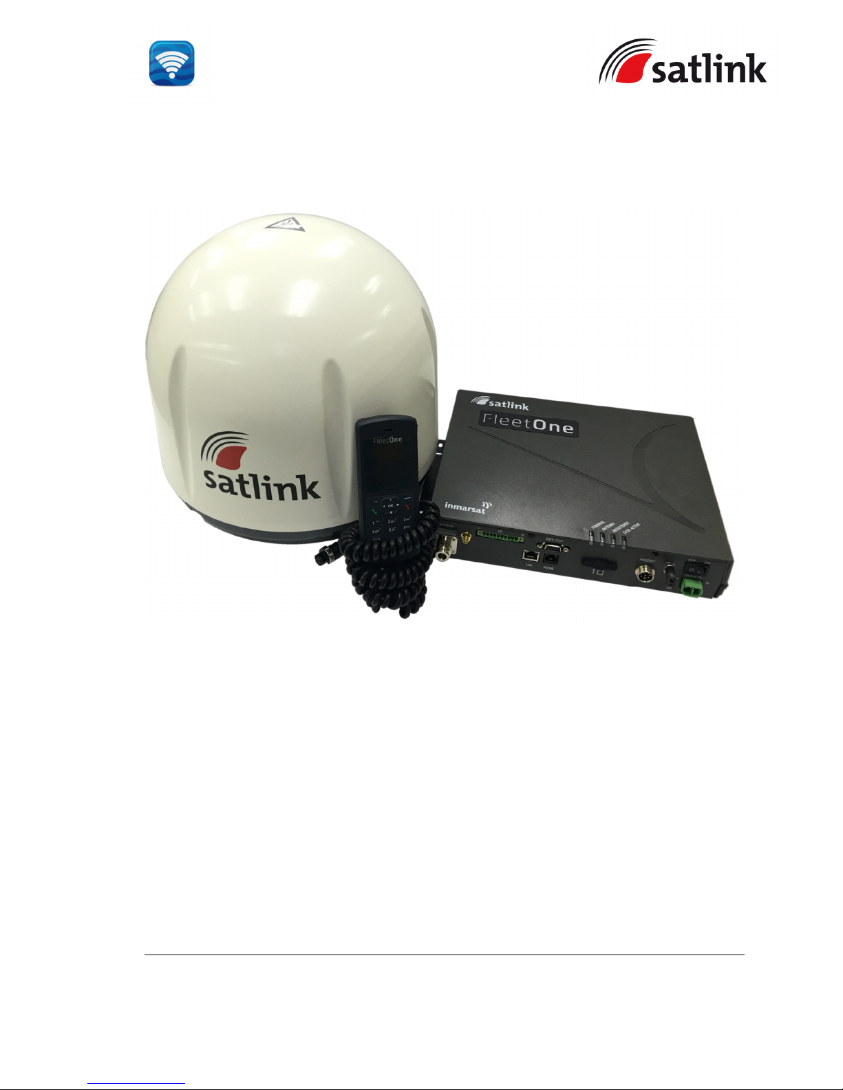
SATLINK FLEET ONE Installation Manual Ref: SL00-01191 Ver: 003
Page 1 of 38
Proprietary Information Not To Be Disclosed Without Written Authorisation From
Satlink S.L., All Rights Reserved
Installation Manual
Revision 1.0
For assistance or additional about this Installation Manual, please contact SATLINK S.L.
Customer Support at:
Whilst the above information has been prepared by Satlink S.L. in good faith, and all
reasonable efforts have been made to ensure its accuracy, Satlink S.L. makes no warranty or
representation as to the accuracy, completeness, or fitness for purpose or use of the
information. Satlink S.L. shall not be liable for any loss or damage of any kind, including
indirect or consequential loss, arising from use of the information and all warranties and
conditions, whether express or implied by statute, common law or otherwise, are hereby
excluded to the extent permitted by English law.
Page 2

SATLINK FLEET ONE Installation Manual Ref: SL00-01191 Ver: 003
Page 2 of 38
Proprietary Information Not To Be Disclosed Without Written Authorisation From
Satlink S.L., All Rights Reserved
CONTENTS:
CERTITICATIONS_________________________________________________________________ 4
SAFETY INSTRUCTIONS __________________________________________________________ 6
IMPORTANT INFORMATION TO INSTALLERS AND USERS ___________________________ 9
SYSTEM CONFIGURATION _______________________________________________________ 11
User Equipment Lists ______________________________________________________________ 12
1 FLEET ONE USER EQUIPMENT _______________________________________________ 13
1.1 Introduction _____________________________________________________________ 13
1.2 Above Deck Equipment ____________________________________________________ 13
1.3 Below Deck Equipment ____________________________________________________ 14
1.4 Wired Primary Handset with Cradle _________________________________________ 14
2 INSTALLATION OF FLEET ONE TERMINAL ____________________________________ 15
2.1 Installation of ADU _______________________________________________________ 15
2.1.1 Overview ____________________________________________________________ 15
2.1.2 Radiation Hazard ______________________________________________________ 15
2.1.3 Interference ___________________________________________________________ 16
2.1.4 Obstruction ___________________________________________________________ 18
2.1.5 Antenna Mast _________________________________________________________ 19
2.1.6 Installing Antenna Unit _________________________________________________ 20
2.2 Installation of BDU ________________________________________________________ 20
2.3 Installation of Primary Handset _____________________________________________ 23
3 CONNECTIONS ______________________________________________________________ 24
3.1 BDU’s Outputs Connection _________________________________________________ 25
3.1.1 GPS Output Connector __________________________________________________ 25
3.1.2 GPIO Port ____________________________________________________________ 26
3.1.3 Grounding Stud _______________________________________________________ 27
4 GETTING STARTED ON THE SYSTEM __________________________________________ 27
4.1 Installing the SIM card ____________________________________________________ 27
4.2 Powering up the system ____________________________________________________ 29
4.2.1 Switching on the BDU __________________________________________________ 29
4.3 Settings on Web Console ___________________________________________________ 30
4.3.1 Activating on Web Console ______________________________________________ 30
4.3.2 Activating PDP Context _________________________________________________ 31
4.3.3 Deactivating PDP Context _______________________________________________ 32
5 GLOSSARY __________________________________________________________________ 33
APPENDIX A OUTLINE DRAWINGS ________________________________________________ 34
Page 3

SATLINK FLEET ONE Installation Manual Ref: SL00-01191 Ver: 003
Page 3 of 38
Proprietary Information Not To Be Disclosed Without Written Authorisation From
Satlink S.L., All Rights Reserved
A-1 ADU’s Outline Dimensions and Weight _______________________________________ 34
A-2 ADU’s Hole Pattern (Cut-out Holes) _________________________________________ 35
A-3 BDU’s Outline Dimensions _________________________________________________ 36
A-4 Primary Handset’s Outline Dimensions _______________________________________ 36
APPENDIX B GPIO PORT _________________________________________________________ 37
B-1 Data Connection Switch ____________________________________________________ 37
Page 4

SATLINK FLEET ONE Installation Manual Ref: SL00-01191 Ver: 003
Page 4 of 38
Proprietary Information Not To Be Disclosed Without Written Authorisation From
Satlink S.L., All Rights Reserved
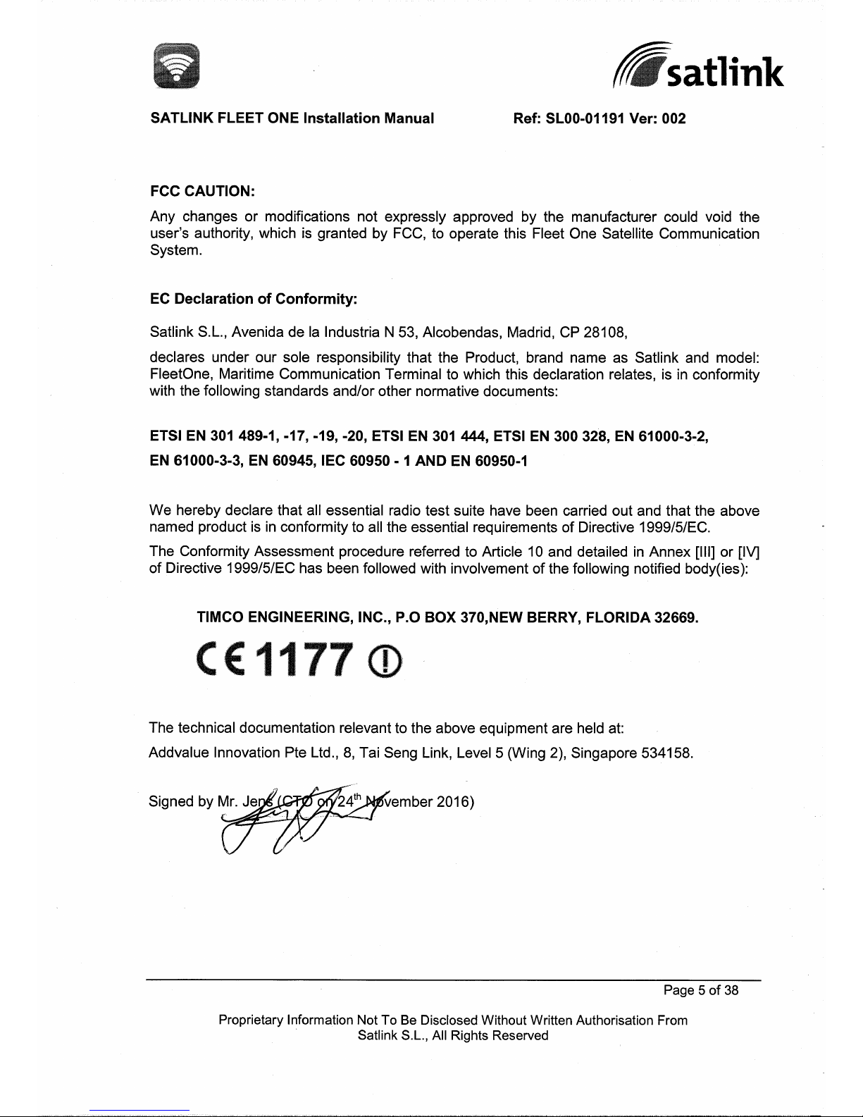
CERTITICATIONS
FEDERAL COMMUNICATION COMMISSION NOTICE
FCC Identifier: XGW-SLFLTONE
USE CONDITIONS
This device complies with Part 15 of the FCC Rules. Operation is subject to the following two
conditions:
(1) This device may not cause harmful interference, and
(2) This device must accept any interference received, including interference that may
cause undesired operation.
NOTE
This equipment has been tested and found to comply with the limits for a Class B digital
device, pursuant to Part 15 of the FCC Rules. These limits are designed to provide reasonable
protection against harmful interference in a residential installation. This equipment generates
uses and can radiate radio frequency energy and, if not installed and used in accordance with
the instructions, may cause harmful interference to radio communications. However, there is
no guarantee that interference will not occur in a particular installation.
If this equipment does cause harmful interference to radio or television reception, which can
be determined by turning the equipment off and on, the user is encouraged to try to correct the
interference by one of the following measures:
· Reorient or relocate the receiving antenna.
· Increase the separation between the equipment and receiver.
· Connect the equipment into an outlet on a circuit different from that to which the receiver
is connected.
· Consult the dealer or an experienced radio/TV technician for help.
IMPORTANT NOTE: EXPOSURE TO RADIO FREQUENCY RADIATION
This device complies with FCC radiation exposure limits set forth for an uncontrolled
environment. The antenna used for this transmitter must be installed to provide a separation
distance of at least 1m from all persons and must not be co-located or operating in
conjunction with any other antenna or transmitter.
Page 5
Page 6
SATLINK FLEET ONE Installation Manual Ref: SL00-01191 Ver: 003
Page 6 of 38
Proprietary Information Not To Be Disclosed Without Written Authorisation From
Satlink S.L., All Rights Reserved
SAFETY INSTRUCTIONS
For the sake of safety and protection, read the manual before attempting to use Fleet One
User Equipment (UE).
The following general safety precautions must be observed during all phases of operation,
service and repair of this equipment. Failure to comply with these precautions or with specific
warnings elsewhere in this user guide violates safety standards of intended use of the UE.
Satlink S.L., assumes no liability for the customer's failure to comply with these requirements.
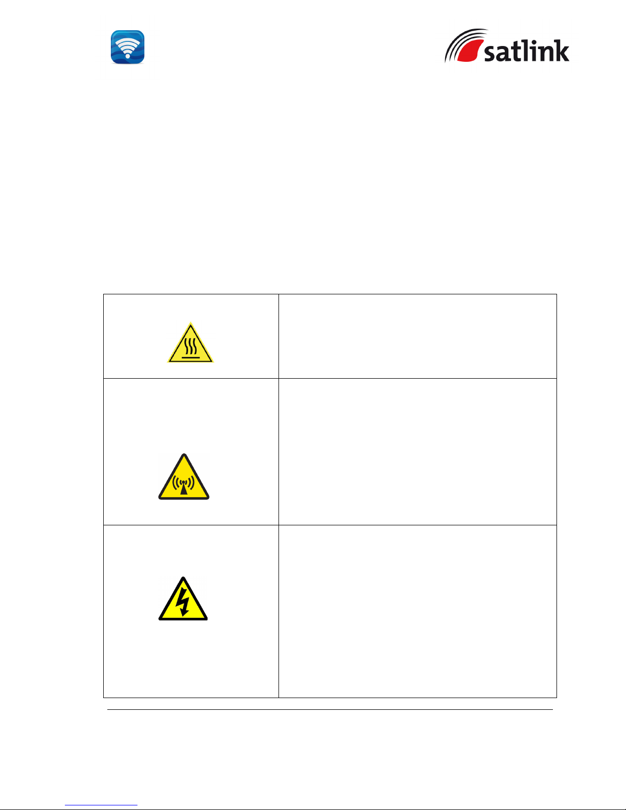
Hazard Symbols
Heat Surfaces
Avoid touching those areas of the UE that are being
marked with this symbol otherwise it may result in injury.
Antenna Radiation Warning
and Distance to other
Radiation Equipment
For safety reasons, all personnel must keep at least
ONE meter from the antenna.
Power Supply
Turn off the power at the mains switchboard before
beginning of the installation.
Confirm the power voltage is compatible with voltage
rating of the equipment. It is highly recommended to use
+24V DC power line, provided that it is available on the
vessel.
If there is no +24V DC power line provided by the vessel,
an external AC/DC power supply with an input of
115/230V AC and an output of +24V DC can be used.
Page 7
SATLINK FLEET ONE Installation Manual Ref: SL00-01191 Ver: 003
Page 7 of 38
Proprietary Information Not To Be Disclosed Without Written Authorisation From
Satlink S.L., All Rights Reserved
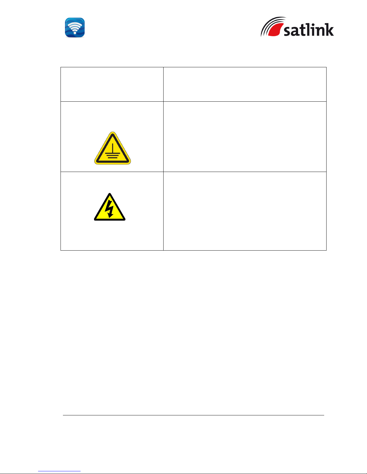
Note:
The requirements of the AC/DC power supply
should take care of high surge current of 25A at 24V
DC for 1ms.
Grounding, cables and
connections
The chassis of the equipment must be connected to an
electrical ground. This will minimise electric shock and
mutual interference. In short, the UE must be grounded
to the vessel.
Service
Do not attempt to access to the interior of the equipment.
Only qualified personnel authorized by its manufacturer
may perform service. Failure to comply with this rule will
result in the warranty void.
Under certain conditions, dangerous voltages may exist
even with the power cable removed. To avoid injuries,
always disconnect power before accessing the
equipment.
Equipment Ventilation
To ensure adequate cooling of the terminal, 5 centimeters of unobstructed space must be
maintained around all sides of the unit except the bottom side. The operational temperature
range of the transceiver is: -25°C to +55°C.
Fire Precautions
The equipment shall not be operated in the presence of flammable gases or fumes as well as
any explosive atmosphere. Operation of any electrical equipment in such an environment
constitutes a definite safety hazard.
Obtaining Licensing For Inmarsat Transceivers
Under rights given under ITU Radio Regulations, local telecommunications administrations
establish and enforce national rules and regulations governing types of emissions, power
levels, and other parameters that affect the purity of signal, which may be radiated in the
various frequency bands of the radio spectrum.
Page 8

SATLINK FLEET ONE Installation Manual Ref: SL00-01191 Ver: 003
Page 8 of 38
Proprietary Information Not To Be Disclosed Without Written Authorisation From
Satlink S.L., All Rights Reserved
To legally operate Inmarsat equipment, it is necessary to obtain permission from the local
telecommunications regulatory authorities of the country you are operating from. Using your
equipment in any country without permission causes you to run the risk of confiscation of the
equipment by the local authorities. The normal procedure to bring such equipment into another
country is to apply for a license before travel. If a license has not been obtained before travel,
the equipment may be put in to storage by local authorities until such time that a license is
obtained.
Page 9

SATLINK FLEET ONE Installation Manual Ref: SL00-01191 Ver: 003
Page 9 of 38
Proprietary Information Not To Be Disclosed Without Written Authorisation From
Satlink S.L., All Rights Reserved
IMPORTANT INFORMATION TO INSTALLERS AND USERS
General
It is important that the user of this equipment read and observe all safety requirements and
operate the terminal according to the descriptions published in this manual.
Failure to comply may result in risk of injury or equipment failure and voids the validity of the
warranty provided by equipment manufacturer.
The terminal consists of 2 systems, BDU and ADU and they must be used as provided by the
manufacturer or authorized dealer. Do not substitute any one of the system which is not
provided by the manufacturer or authorized dealer. Should needs of servicing or replacement
is required, always contact the distributor or manufacturer for instructions.
Any modifications or attempts to open up the devices by not authorized personnel will void the
warranty.
Contents in this manual are subjected to change without notice and may contain errors or
inaccuracies. The manual us periodically revised and updated. To obtain latest version, please
enquire it from product manufacturer or distributor.
Copyright
© Copyright 2016 Satlink S.L.
All rights reserved. This publication and its contents are proprietary to Satlink S.L. No part of
this publication may be reproduced in any form or by any means without the written permission
of Satlink S.L.
Warranty
Satlink S.L. has made every effort to ensure the correctness and completeness of the material
in this document. Satlink S.L. shall not be liable for errors contained herein. The information in
this document is subject to change without notice. Satlink S.L. makes no warranty of any kind
with regard to this material, including, but not limited to, the implied warranties of
merchantability and fitness for a particular purpose.
Trademarks
All trademarks, marks, names, or product names referenced in this publication are the
property of their respective owners, and Satlink S.L. neither endorses nor otherwise sponsors
any such products or services referred to herein.
Page 10

SATLINK FLEET ONE Installation Manual Ref: SL00-01191 Ver: 003
Page 10 of 38
Proprietary Information Not To Be Disclosed Without Written Authorisation From
Satlink S.L., All Rights Reserved
Microsoft, Windows, Windows NT, Windows 2000, Windows XP and Windows 7 are registered
trademarks of Microsoft Corporation in the U.S.A. and/or other countries.
All other company and product names may be the registered trademarks or trademarks of their
respective owners.
Page 11
SATLINK FLEET ONE Installation Manual Ref: SL00-01191 Ver: 003
Page 11 of 38
Proprietary Information Not To Be Disclosed Without Written Authorisation From
Satlink S.L., All Rights Reserved
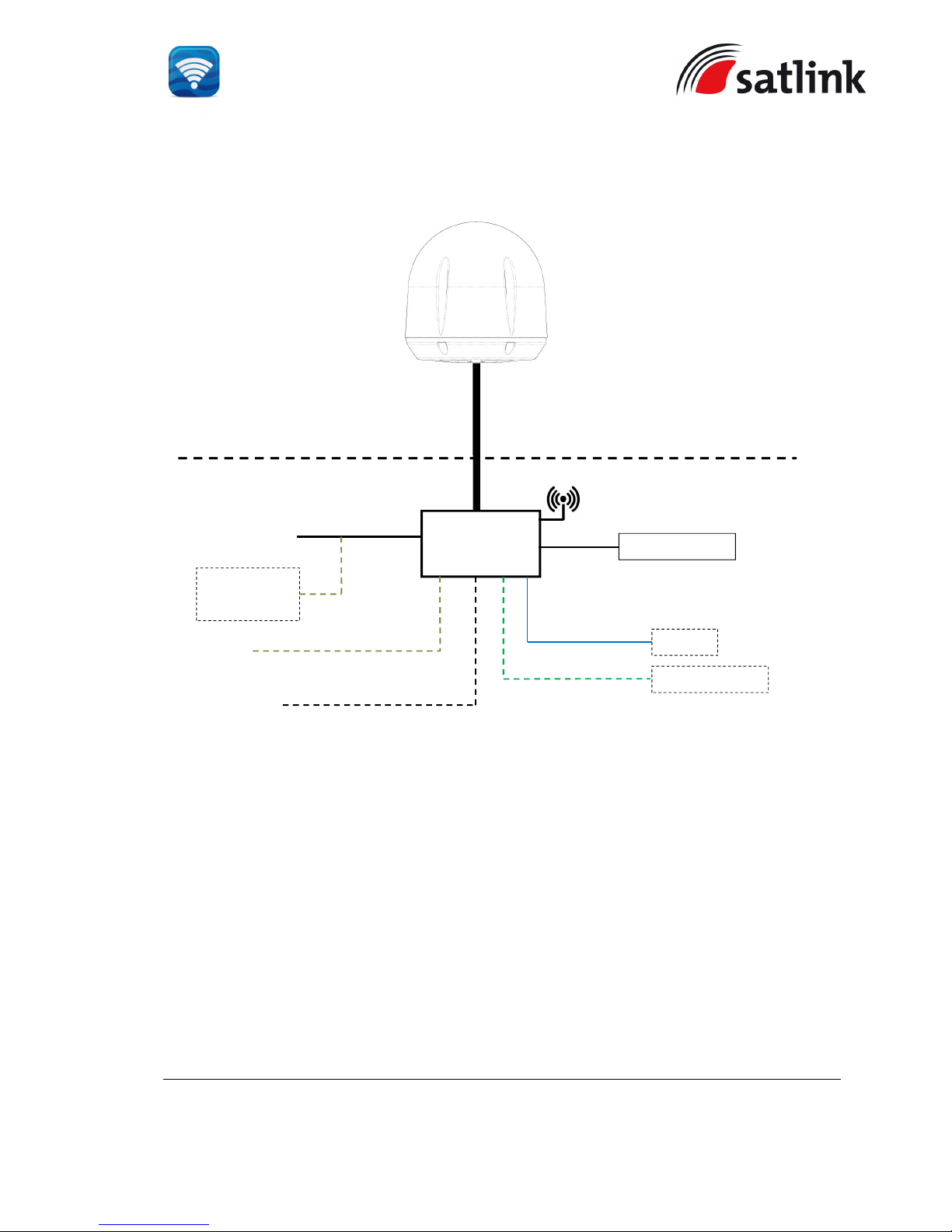
SYSTEM CONFIGURATION
Solid line refers to the basic configuration.
FLEET ONE ADU
FLEET ONE
BDU
Router
External Devices
Above Deck Unit
(To be installed in an exposed area)
Below Deck Unit
(To be installed in protected area)
AC/DC Power
Supply Unit
RJ45
I/O Interface
Navigation
Equipment
GPS O/P (NMEA 0183)
Wi-Fi
RS232 Serial
Analog Phone
15-m Antenna Cable
+12V / +24V DC
RJ11
Primary Handset
Page 12
SATLINK FLEET ONE Installation Manual Ref: SL00-01191 Ver: 003
Page 12 of 38
Proprietary Information Not To Be Disclosed Without Written Authorisation From
Satlink S.L., All Rights Reserved
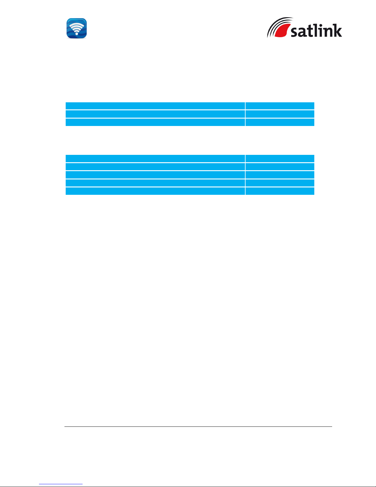
USER EQUIPMENT LISTS
Fleet One Complete Standard Package
Description
Order Code
Satlink Fleet One BDU with Primary Handset FLV2-9TU00-01
Satlink Fleet One ADU with 15-meter Antenna Cable FLV2-0AN00-01
Fleet One Accessories
Description
Order Code
Fleet One Primary Handset FLV2-0PH00-01
Handset Wall Mount Cradle SG5000/WMC
Power Supply 240W AC/DC DIN Rail 24V DC/10A SKP150/ADPS
Antenna Pole Mount with Mounting Kit FX25-0PM00-01
Page 13

SATLINK FLEET ONE Installation Manual Ref: SL00-01191 Ver: 003
Page 13 of 38
Proprietary Information Not To Be Disclosed Without Written Authorisation From
Satlink S.L., All Rights Reserved
1 FLEET ONE USER EQUIPMENT
1.1 Introduction
The Fleet One UE consists of three units;
Below Deck Equipment (BDU) which is a communication unit
Above Deck Equipment (ADU) which is an antenna unit
Wire Primary Handset with cradle
1.2 Above Deck Equipment
The ADU is a 3-axis controlled antenna unit which is self-tracking.
The radome covers the antenna unit, which is comprised of
Antenna Module
RF and GPS Module
Rotary Joint
Antenna Pedestal
The antenna module includes a low noise amplifier (LNA), high power amplifier (HPA), and
tracking receiver circuitry. All the signals and power pass through a single coaxial antenna
cable, which connects the ADU to the BDU.
Page 14
SATLINK FLEET ONE Installation Manual Ref: SL00-01191 Ver: 003
Page 14 of 38
Proprietary Information Not To Be Disclosed Without Written Authorisation From
Satlink S.L., All Rights Reserved
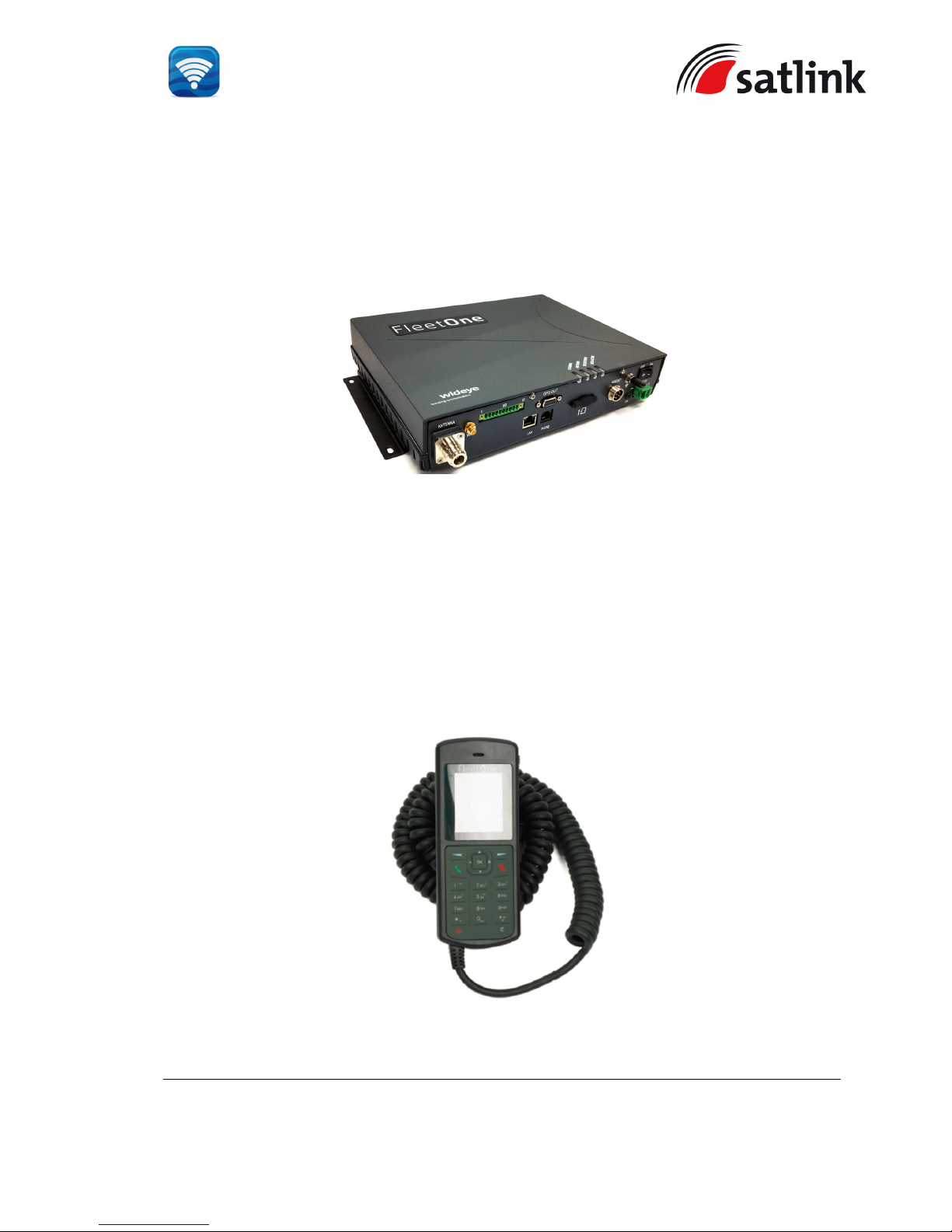
1.3 Below Deck Equipment
The BDU is the heart unit of the Fleet One UE. It has several interface ports and handles all
communication links between the ADU, Primary Handset and the local communication devices
such as analogue telephone, computer, network equipment, navigation equipment etc.
The BDU requires +12V or +24V DC power supply input. It supplies power to the ADU via a
single RF / coaxial antenna cable.
1.4 Wired Primary Handset with Cradle
The wired Primary Handset has a colour liquid crystal display (LCD) and keypad for making
and receiving normal voice calls and sending SMS, similar to any mobile phone. The handset
is provided with a cradle.
Additionally, it can serve as a remote access device for user to access various configuration
parameters supported by the BDU.
The Primary Handset’s connector is plugged into the BDU’s primary handset port. It is
powered directly from the BDU.
Page 15
SATLINK FLEET ONE Installation Manual Ref: SL00-01191 Ver: 003
Page 15 of 38
Proprietary Information Not To Be Disclosed Without Written Authorisation From
Satlink S.L., All Rights Reserved
2 INSTALLATION OF FLEET ONE TERMINAL
2.1 Installation of ADU
2.1.1 Overview
In general, any obstructing objects like a mast near the antenna unit can block reception or
transmission from the satellite’s line of sight. In addition, RF radiation emitting from the
antenna will affect the human body. When selecting a mounting location, it is important to
ensure that the antenna unit shall be free of severe vibration and shock and heat and smoke
from funnel. More guidelines will be detailed in the next sections.
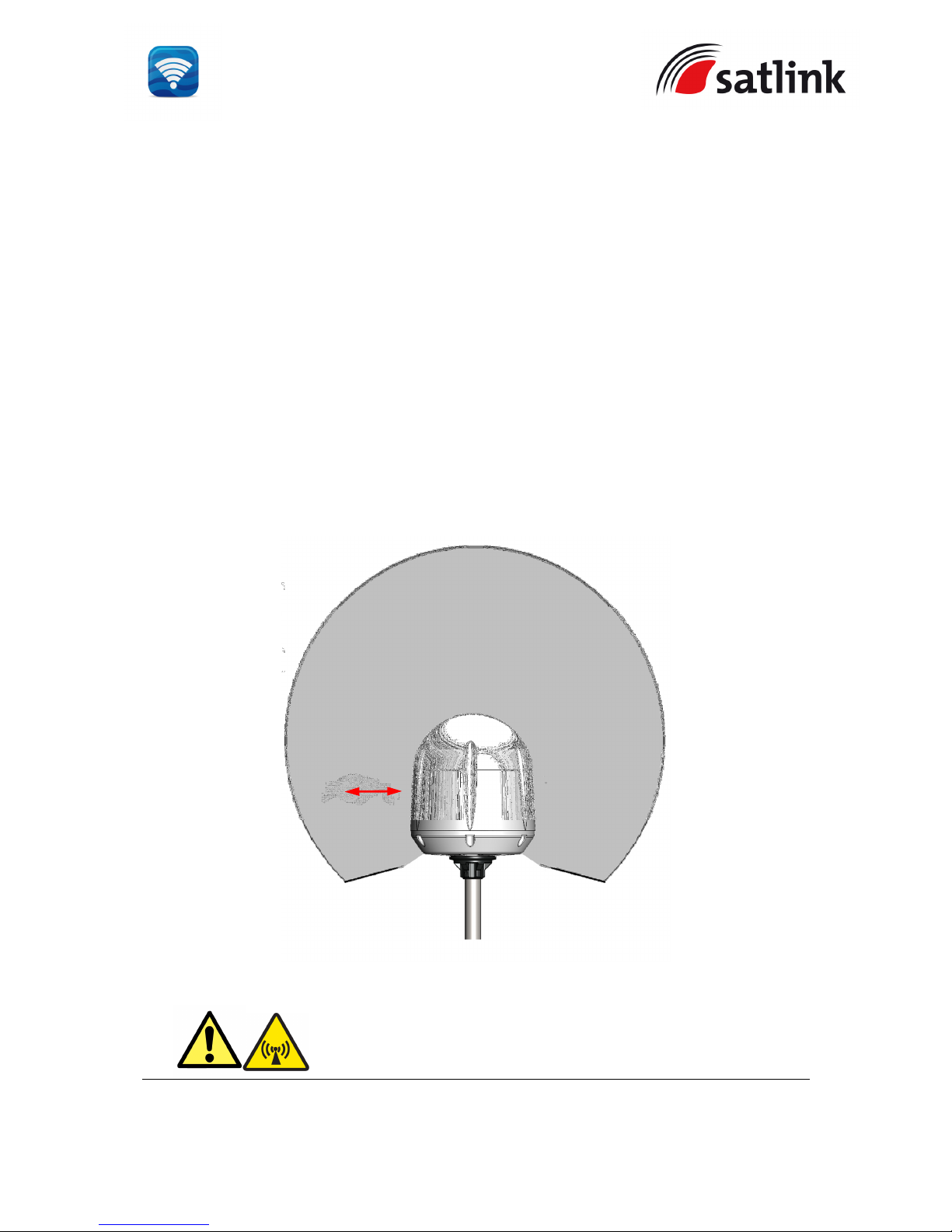
2.1.2 Radiation Hazard
Radio wave can pose hazard to human body. Safe distances are changed, subjected to
country and ship construction. There is no standard formula to calculate safe distance. The
below guidelines are to be noted.
Fleet One ADU
WARNING: Keep away from the antenna radome at the mentioned
safe distance when it is transmitting. Microwave radiation can be
harmful to human body, particularly the eyes.
MICROWAVE RADIATION !
NO ADMITTANCE WITHIN SAFETY
DISTANCE
Safety distance
1m
ANTENNA
UNIT
Page 16
SATLINK FLEET ONE Installation Manual Ref: SL00-01191 Ver: 003
Page 16 of 38
Proprietary Information Not To Be Disclosed Without Written Authorisation From
Satlink S.L., All Rights Reserved
2.1.3 Interference
The antenna unit must be mounted as far as possible away from the/HF antennas,
communication/navigations, VSAT systems and any high power radio transmitter (including
other Inmarsat-based systems).
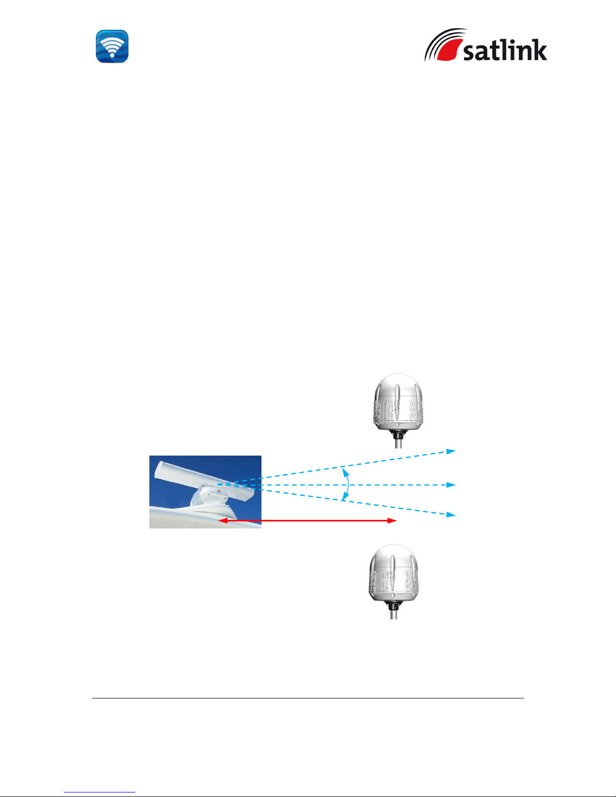
Radar
It is difficult to provide the exact minimum distance between a radar and the antenna
unit due to different type of radars in terms of power, radiation pattern and operating
frequency band.
The antenna unit is recommended to be at least ±15⁰ from the radar’s vertical beam.
The minimum radar distance indicates the minimum distance between the closest
point of the radar and the closest surface of the antenna radome. This distance is
determined by the radar, transmit frequency and the power.
Minimum
Distance
, d
+15º (Min)
-15º (Min)
Antenna
Unit
Antenna
Unit
Page 17
SATLINK FLEET ONE Installation Manual Ref: SL00-01191 Ver: 003
Page 17 of 38
Proprietary Information Not To Be Disclosed Without Written Authorisation From
Satlink S.L., All Rights Reserved
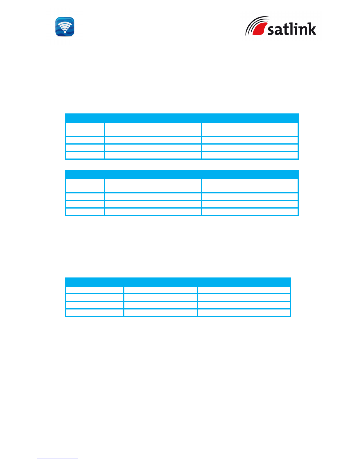
Below is the table gives the recommended minimum distance d between X- and Sband radars and the antenna. Antenna damage is normally avoided by applying the
distance.
Antenna l
ocation at the minimum distance from Radar (
S-Band)
Radar
Power
Min distance (d) at ±15⁰ vertical
separation
min distance (d) at ±60⁰ vertical
separation
0 - 12 kW 0.5 m 0.3 m
30 kW 1.0 m 0.5 m
50 kW 2.0 m 1.0 m
Antenna l
ocation at the minimum distance from Radar (X
-
Band)
Radar
Power
min distance (d) at ±15⁰ vertical
separation
min distance (d) at ±60⁰ vertical
separation
0 - 12 kW 0.9 m 0.5 m
30 kW 2.4 m 1.2 m
50 kW 4.0 m 2.0 m
Transmitting Equipment < 1GHz
HF and VHF transmitters can also interfere with the performance of the antenna and
also damage the antenna if placed close. The table below gives guide lines to the
minimum distance between the antenna and HF and VHF transmitters.
Antenna l
ocation at the minimum distance from
HF / VHF
Type
Power
Distance
HF < 60MHz 100 W 1.0 m
HF < 60 MHz 500 W 2.5 m
VHF > 60 MHz 25 W 1.5 m
VSAT System
For optimum performance the distance between the antenna and VSAT antennas
should be at least 3 meter.
GPS Antenna
As the antenna transmits power close to the GPS receive band, the minimum
distance to GPS antennas is typically 5 meter.
Page 18

SATLINK FLEET ONE Installation Manual Ref: SL00-01191 Ver: 003
Page 18 of 38
Proprietary Information Not To Be Disclosed Without Written Authorisation From
Satlink S.L., All Rights Reserved
Other L-Band Systems
Typical L-Band satellite communication equipment should be able to operate in close
proximity without loss of performance ( Refer to Section 2.1.4 Distance to obstruction
objects). It is to be noticed that such equipment typically includes GPS antennas, and
that it can be necessary to use the typical minimum distance of typically 5 meter.
2.1.4 Obstruction
When locating the antenna, it is very important to ensure that there is a clear line-of-sight to
the satellite for all the satellite elevation angles in the region in which the vessel will operate.
The antenna moves in azimuth 360⁰ and in roll and pitch down to -25⁰ to ensure constant
tracking even in heavy sea. Any obstructions within this arc can cause performance
degradations on the signal quality. The amount of degradation depends on the size of the
obstruction and distance from the antenna. The table below is a guide line on the object size,
at a given distance from the antenna that gives limited degradation.
Object Distance
Object Size
3 m 16 cm
6 m 32 cm
10 m 52 cm
15 m 79 cm
Page 19
SATLINK FLEET ONE Installation Manual Ref: SL00-01191 Ver: 003
Page 19 of 38
Proprietary Information Not To Be Disclosed Without Written Authorisation From
Satlink S.L., All Rights Reserved
2.1.5 Antenna Mast
The antenna unit should be located at least 3-meter away from the ship’s mast having a
diameter of less than 15cm. If the antenna mast is available on the vessel and it is free of
any shock or vibration, its physical size shall support the weight and size of that Fleet One
ADU.
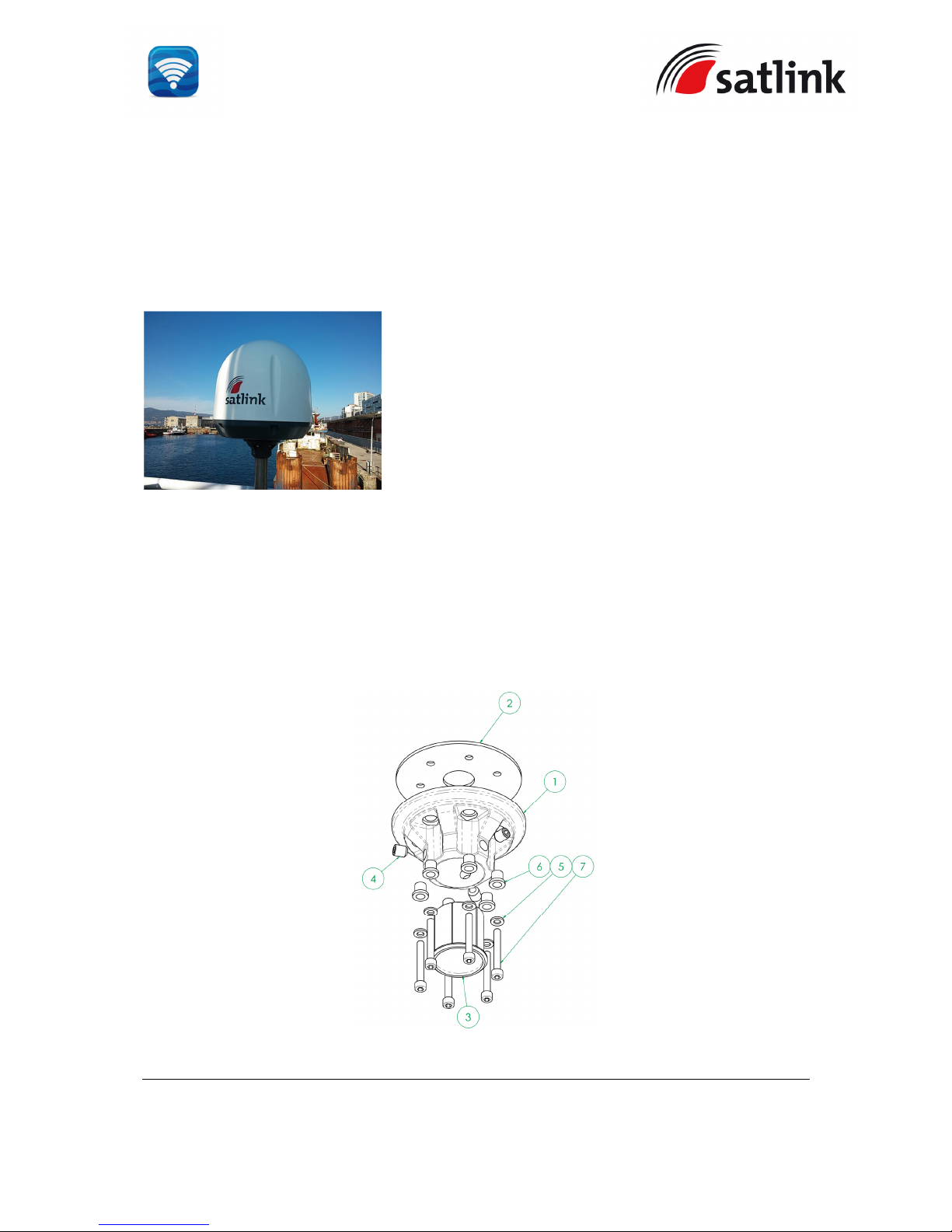
An example of the antenna mast is illustrated as below and the recommendations of the
antenna mast:
The antenna must be installed using Satlink mounting kit SL40-01937 that includes a flange
to be mounted on the antenna.
The antenna must be mounted on a 40mm stainless steel tube and run the coaxial cable
inside the tube.
The Satlink mounting kit flange is designed to meet the dimensions of the ADU’s mounting
base, where there are 6 holes.
The rubber gasket is required to be inserted between the ADU mounting base and the flange
.
[1] Flange
[2] Gasket
[3] Tube cap for 40mm tube
[4] 3 tube fixing bolts
[5] Washer
[6] Cap
[7] 6 Screw bolts DIN912 M6 x 45mm
Page 20

SATLINK FLEET ONE Installation Manual Ref: SL00-01191 Ver: 003
Page 20 of 38
Proprietary Information Not To Be Disclosed Without Written Authorisation From
Satlink S.L., All Rights Reserved
2.1.6 Installing Antenna Unit
The antenna unit should be carefully unpacked and checked for any damage.
The procedure of the installation of the antenna unit is as follow:
Find a suitable place for a stainless steel tube and run cable inside tube
Pass the coaxial cable through the flange and gasket
Attach the coaxial cable to the RF connector on the antenna unit’s base.
Ensure the connection of the coaxial cable and wrap it with self-amalgamating tape
for water-proofing.
Put the antenna unit on the mounting flange and the 6 screw bolts with flat washers
and caps into the threaded holes of the antenna unit’s mounting base via the
mounting flange’s holes.
Position the antenna unit onto the tube by placing the tube inside the tube cap.
Tighten the 3 tube fixing bolts in order to secure it to the tube.
Double check all screws and bolts
2.2 Installation of BDU
The BDU’s box is unpacked and the following items should be checked whether they are
present:
BDU
1 x Primary Handset with Cradle
1 x Ethernet Cable
1 x DC Power Cable
1 x Inmarsat 505 laminated card
1 x Wi-Fi Antenna
Hardcopy Quick Start Guide
CD ROM (Soft User Manual)
Cable Support Kit
Page 21
SATLINK FLEET ONE Installation Manual Ref: SL00-01191 Ver: 003
Page 21 of 38
Proprietary Information Not To Be Disclosed Without Written Authorisation From
Satlink S.L., All Rights Reserved
The following important notes are to be followed for the selection of a location before
installing the BDU:
The unit is not water proof and it has to be kept away from water splash.
The ambient temperature and humidity in the selected location must the requirements
given in the unit’s specification.
Ambient Temperature -25ºC to +55ºC
Relative Humidity Up to 95% at +40ºC.
The unit shall be kept away from direct sunlight.
The unit shall be placed away from any high vibration and shock areas (for example,
motor engine and generator) as far as possible.
The unit shall be kept away from other electronic equipment.
The unit has to follow the recommended compass safe distance of 1m to prevent
interference to a magnetic compass
For maintenance and checking, the unit’s location has sufficient space at its sides
and rear.
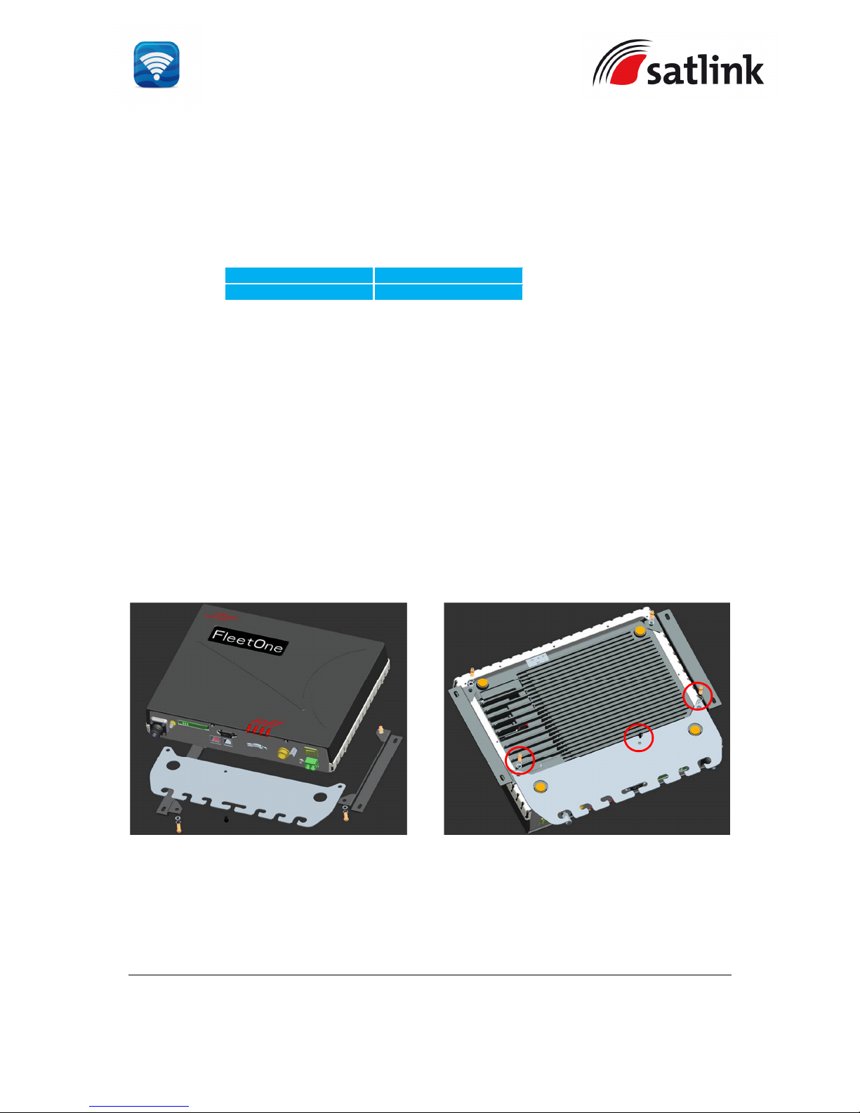
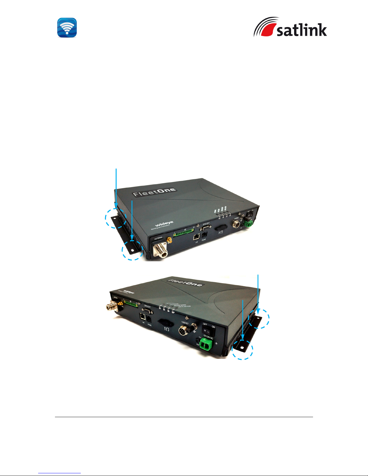
The BDU comes with a cable support item, which is included in the delivery. The cable
support item is to secure the cables from the BDU.
To mount the cable support onto the BDU,
Remove the 2 screws of the front mounting bracket
Mount the cable support item on the bottom of the BDU.
Tighten the same 2 screws to secure the cable support item.
Page 22
SATLINK FLEET ONE Installation Manual Ref: SL00-01191 Ver: 003
Page 22 of 38
Proprietary Information Not To Be Disclosed Without Written Authorisation From
Satlink S.L., All Rights Reserved
The BDU can be installed on a desktop, bulkhead, top ceiling or under captain’s console.
The procedure of the installing the BDU is simple as follow:
Place the BDU on the desired installation area.
Look for the holes of the BDU’s mounting brackets.
Using the holes of mounting brackets and four M4x12mm self-tapping or machined
screws so that the BDU is secured to the selected surface.
Page 23
SATLINK FLEET ONE Installation Manual Ref: SL00-01191 Ver: 003
Page 23 of 38
Proprietary Information Not To Be Disclosed Without Written Authorisation From
Satlink S.L., All Rights Reserved
2.3 Installation of Primary Handset
The primary handset is provided with cradle. It can be mounted on a desktop, bulkhead, top
ceiling or under captain’s console as similar as the BDU.
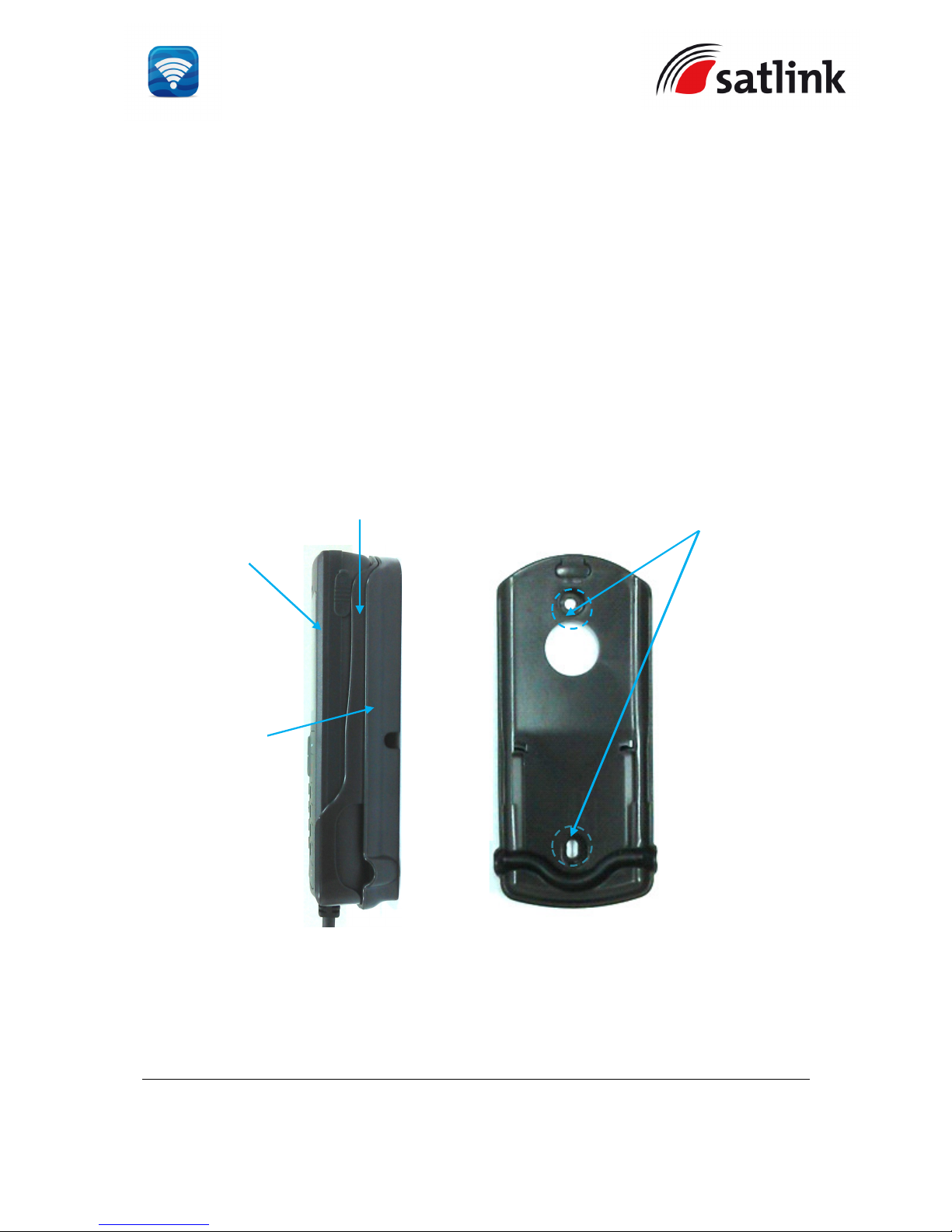
The primary handset is to be separated from its cradle so that the cradle can be fixed with
the M5 x 12mm self-tapping screws.
The procedure of the installing the cradle is simple as follow:
a. Separate the handset from the cradle and remove the plastic cover of the cradle.
b. Position the cradle on the mounting areas.
c. Fix the cradle with M5 x 12mm self-tapping screws, which are supplied.
d. Reattach the plastic cover onto the cradle.
e. Secure the handset onto the cradle.
The primary handset is placed on the cradle and its end connector is plugged securely to the
BDU’s handset circular port.
Handset
Cradle
M5 x 12mm Screw
Plastic Cover
Page 24
SATLINK FLEET ONE Installation Manual Ref: SL00-01191 Ver: 003
Page 24 of 38
Proprietary Information Not To Be Disclosed Without Written Authorisation From
Satlink S.L., All Rights Reserved
3 CONNECTIONS
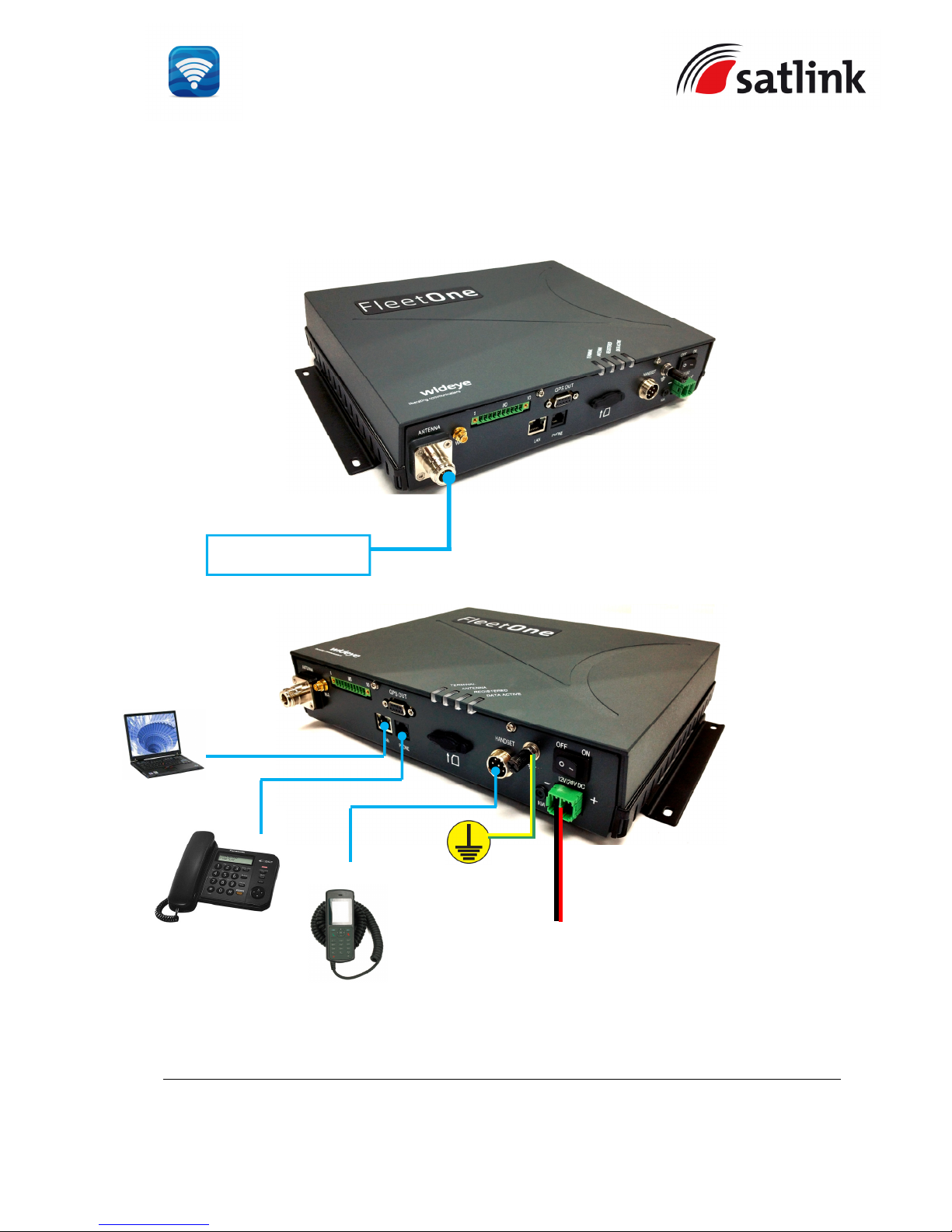
Below is the interconnection diagram of Fleet One Terminal with the cables.
+12V/24V DC
Input from
Vessel’s power
distributor
Bolt to vessel’s
hull
Computer
1.5m Ethernet LAN
(Category 5) Cable
1.8m DC Power
Antenna Unit (ADU)
15-meter Antenna Cable
Primary Handset
1m Handset Cable
Telephone Cable
Standard
Analog Phone
Page 25
SATLINK FLEET ONE Installation Manual Ref: SL00-01191 Ver: 003
Page 25 of 38
Proprietary Information Not To Be Disclosed Without Written Authorisation From
Satlink S.L., All Rights Reserved
3.1 BDU’s Outputs Connection
The additional information of the output ports of GPS and GPIO.
3.1.1 GPS Output Connector
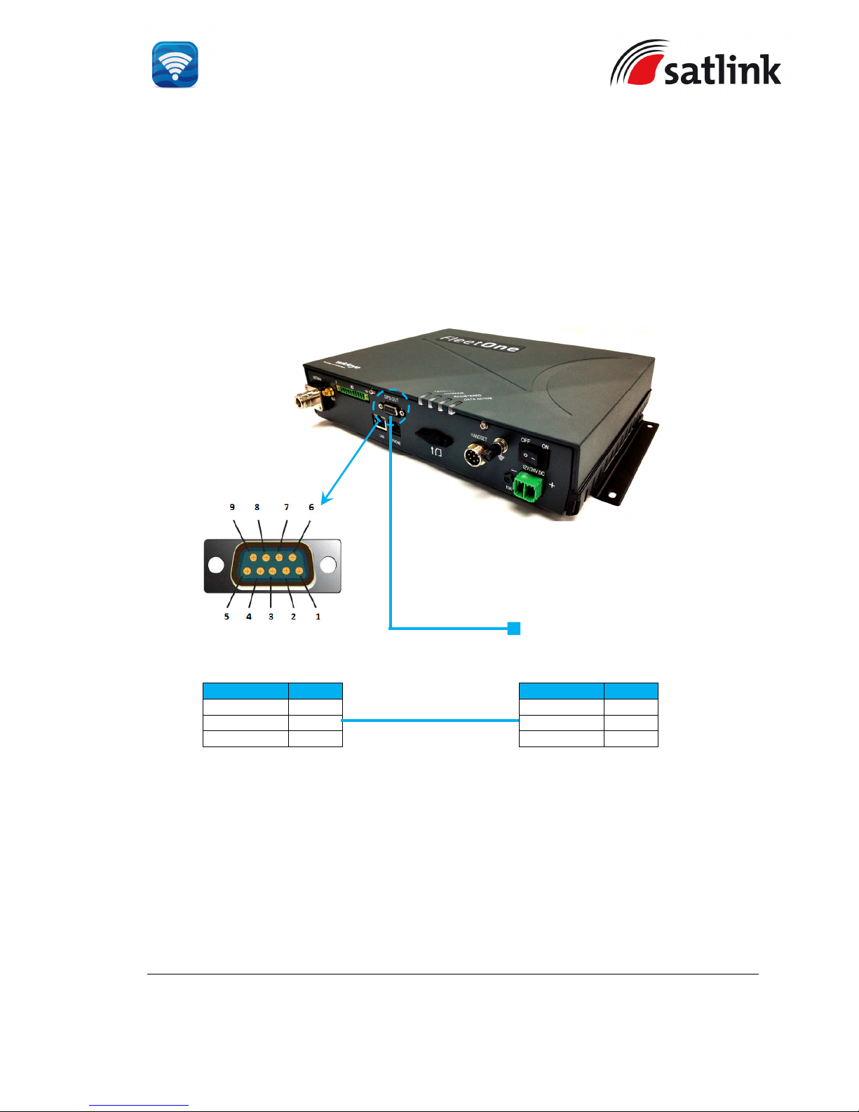
The BDU has
a GPS output (RS-232 serial) connector for outputting the GPS data in
NMEA0183 format.
RS-232 Output Pinout
Pin No.
Signal
Pin 3 TX
Pin 2 RX
Pin 5 GND
Navigation
Equipment
RS-232 Pinout
Pin No.
Signal
Pin 2 RX
Pin 3 TX
Pin 5 GND
Page 26
SATLINK FLEET ONE Installation Manual Ref: SL00-01191 Ver: 003
Page 26 of 38
Proprietary Information Not To Be Disclosed Without Written Authorisation From
Satlink S.L., All Rights Reserved
3.1.2 GPIO Port
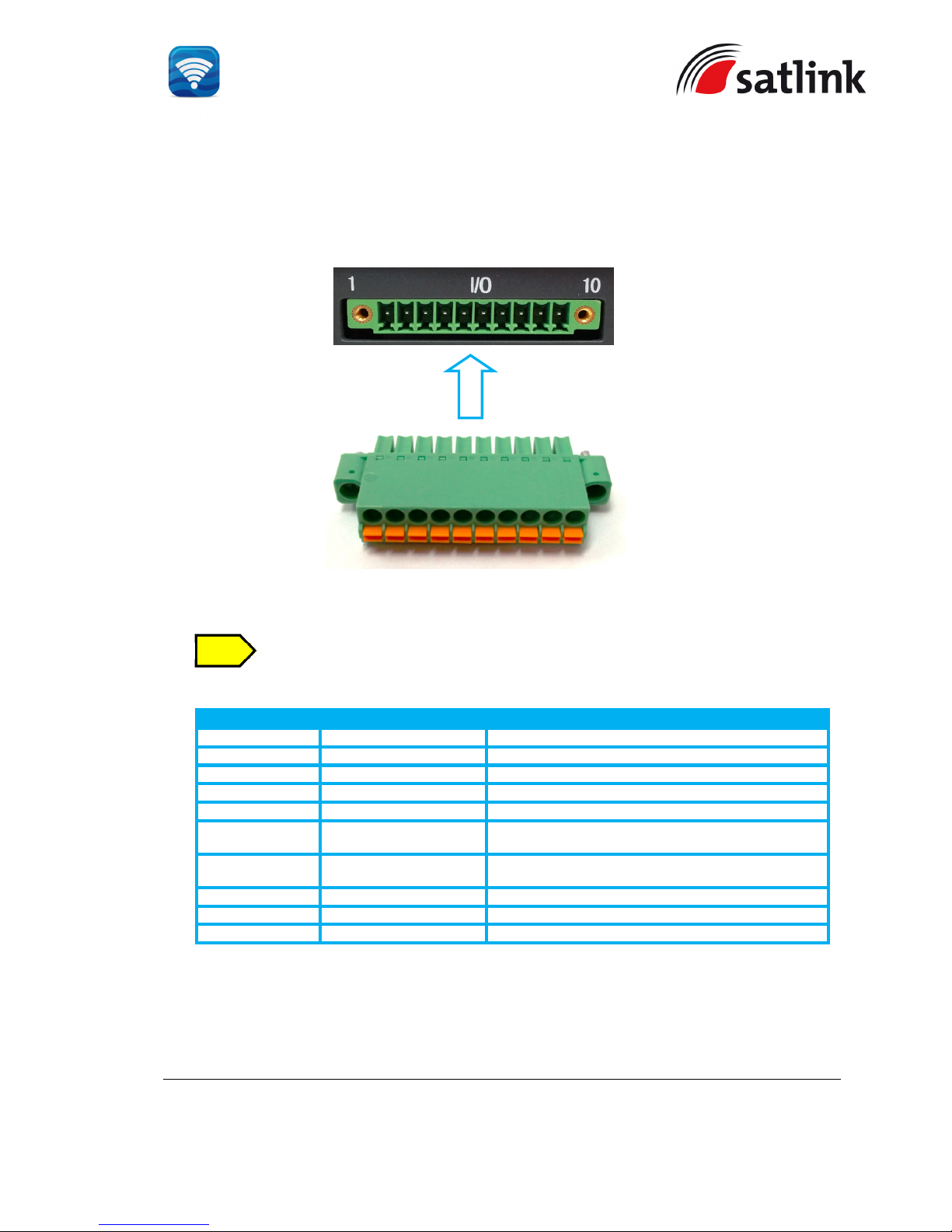
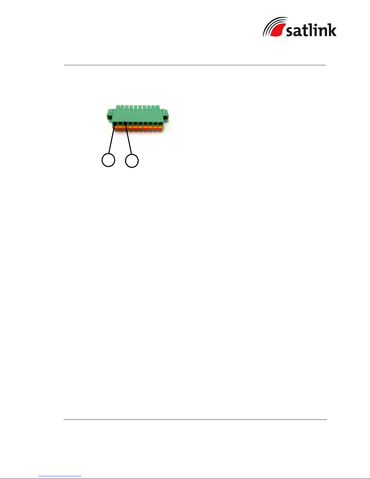
The BDU has a dedicated 10-pin phoenix connector to provide GPIO (General Purpose
Input/Output) interface to the external devices.
A matching connector is included in the delivery..
GPIO Port Pinout
GPIO Port Pin
Signal Name
Description of Signal
GPIO - 1 6V To supply 6V DC source.
GPIO - 2 TX_OFF To disable the antenna unit’s transmitter.
GPIO - 3 PDP_ON/OFF To enable/disable the data connection.
GPIO - 4 BUZZER To enable external ringer / buzzer for incoming call.
GPIO - 5 GND To provide grounding for the whole system.
GPIO - 6 REMOTE_ON/OFF_SW For the connection to Remote ON/ OFF switch away
from the BDU.
GPIO - 7 REMOTE_ON/OFF_LED Power Indicator.
GPIO - 8 Reserve Not in use.
GPIO – 9 Reserve Not in use.
GPIO – 10 GND To provide grounding for the whole system.
All wires for the GPIO connector shall use AWG 24 unscreened wire type.
For the data connection switch, refer to Appendix B - GPIO Port
I/O Connector Pinout
NOTE
Page 27
SATLINK FLEET ONE Installation Manual Ref: SL00-01191 Ver: 003
Page 27 of 38
Proprietary Information Not To Be Disclosed Without Written Authorisation From
Satlink S.L., All Rights Reserved
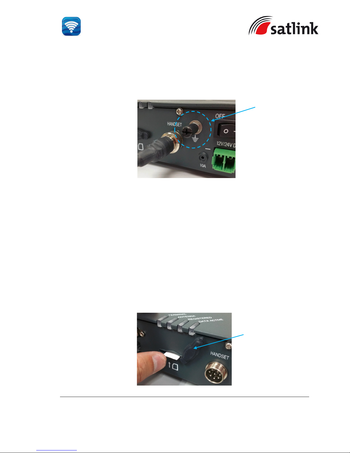
3.1.3 Grounding Stud
The BDU has a grounding stud with a locking screw for the earth cable (with its colors of green
and yellow) with its lug. It is recommended to include spring washers to secure the lug to the
grounding stud.
The other end of the earth cable must have good electrical contact to the vessel’s hull with the
removal of painting, dirt, grease and metal oxide at the mounting holes of the hull.
4 GETTING STARTED ON THE SYSTEM
4.1 Installing the SIM card
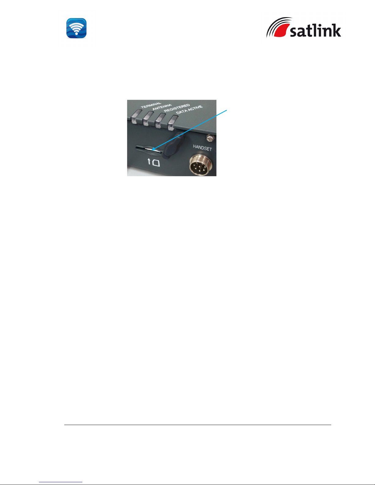
The system requires a Fleet One SIM card to access the Inmarsat’s network and it is provided
by your Airtime Service Provider. Insert the SIM card to the BDU as follow:
Tilt up the SIM card slot’s rubber cover.
Position the SIM card with its gold-contacts facing down. (There is a symbol of SIM Card
with its arrow on the front panel. It will ensure the correct orientation of the SIM Card when
it is being inserted. )
SIM CARD SLOT’s
RUBBER COVER
Grounding Stud
Page 28
SATLINK FLEET ONE Installation Manual Ref: SL00-01191 Ver: 003
Page 28 of 38
Proprietary Information Not To Be Disclosed Without Written Authorisation From
Satlink S.L., All Rights Reserved
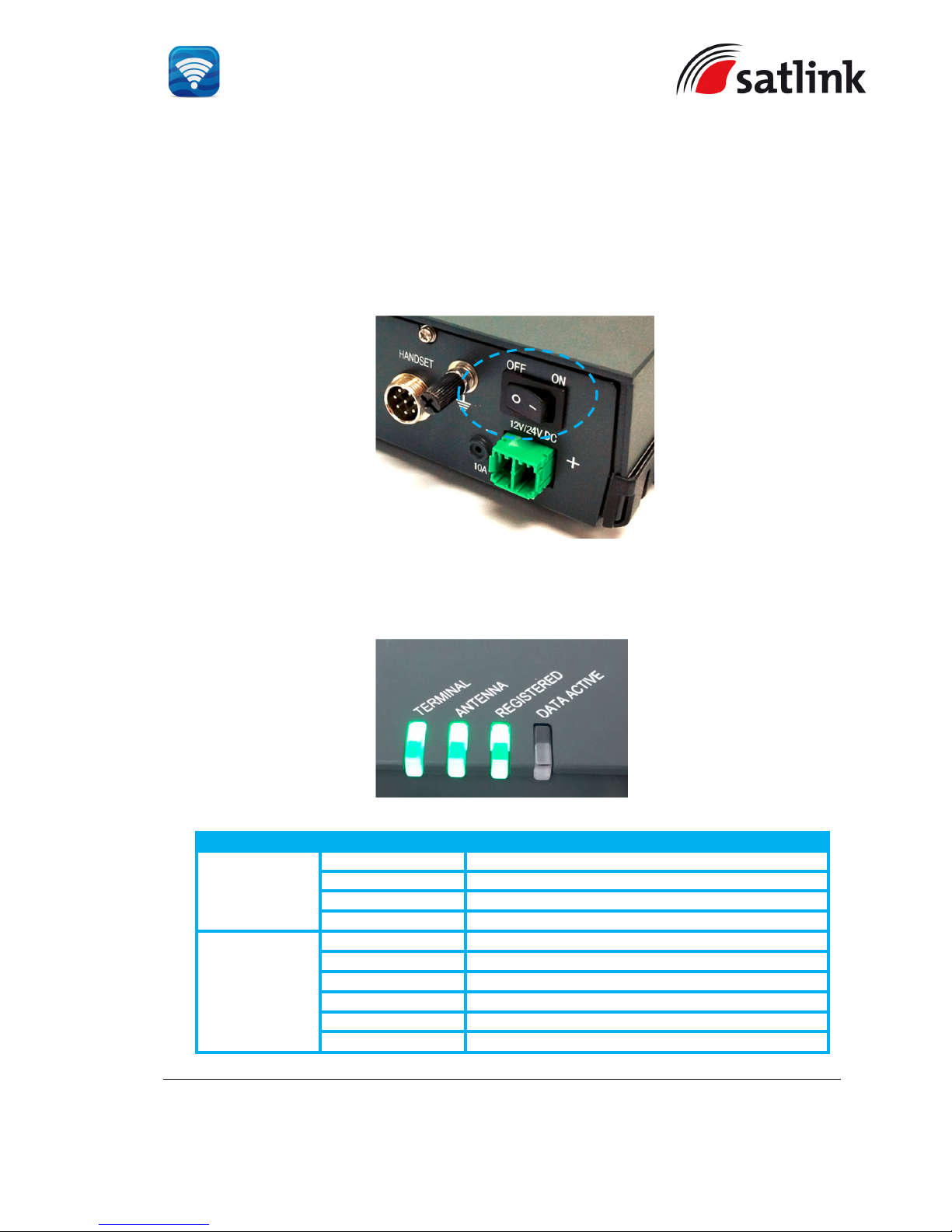
Push the SIM card gently until it is being clicked and locked in place.
Tilt down the SIM card cover to its original position.
SIM CARD
Page 29
SATLINK FLEET ONE Installation Manual Ref: SL00-01191 Ver: 003
Page 29 of 38
Proprietary Information Not To Be Disclosed Without Written Authorisation From
Satlink S.L., All Rights Reserved
4.2 Powering up the system
4.2.1 Switching on the BDU
Use the ON/OFF switch on the BDU’s front panel. It normally takes about 1.5 to 3 minutes for the whole
terminal to be powered up and to register into the satellite network .
Wait for the three LED indicators (“TERMINAL”, ”ANTENNA” and “REGSITERED” ) to turn green.
LED Name
Status
Meaning
TERMINAL
Steady Amber Terminal (BDU) is powering up.
Steady Green Terminal (BDU) has powered up successfully.
Steady Red Terminal (BDU) detects failure state.
Off Terminal (BDU) is in OFF state.
ANTENNA
Steady Amber ADU is powering up.
Blinking Amber ADU is calibrating.
Blinking Green System is performing satellite search.
Steady Green System has locked on to the satellite.
Steady Red ADU detects failure state.
No light (Off) ADU is in OFF state.
Page 30
SATLINK FLEET ONE Installation Manual Ref: SL00-01191 Ver: 003
Page 30 of 38
Proprietary Information Not To Be Disclosed Without Written Authorisation From
Satlink S.L., All Rights Reserved
REGISTERED
Steady Amber Attempting network registration
Blinking Amber Ready for Voice only.
Blinking Green Ready for Data only.
Steady Green Ready for all (Voice and Data).
Steady Red Network failure / Registration error.
No light (Off) No network service.
DATA ACTIVE
Steady Amber Activating data connection.
Steady Green Data connection is ready.
Steady Red Data activation failure
No light (Off) No data connection.
4.3 Settings on Web Console
4.3.1 Activating on Web Console
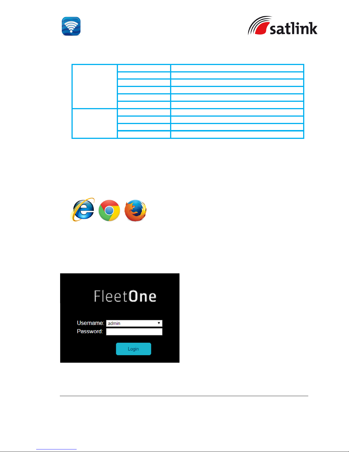
Open the web browser (for example: Internet Explorer, Google Chrome or Firefox.)
and type http://192.168.1.35/ in the Address field.
Username and Password will be prompted.
Default Username : admin
Password : 1234
Click “Login” after entering the Username and Password.
Page 31
SATLINK FLEET ONE Installation Manual Ref: SL00-01191 Ver: 003
Page 31 of 38
Proprietary Information Not To Be Disclosed Without Written Authorisation From
Satlink S.L., All Rights Reserved
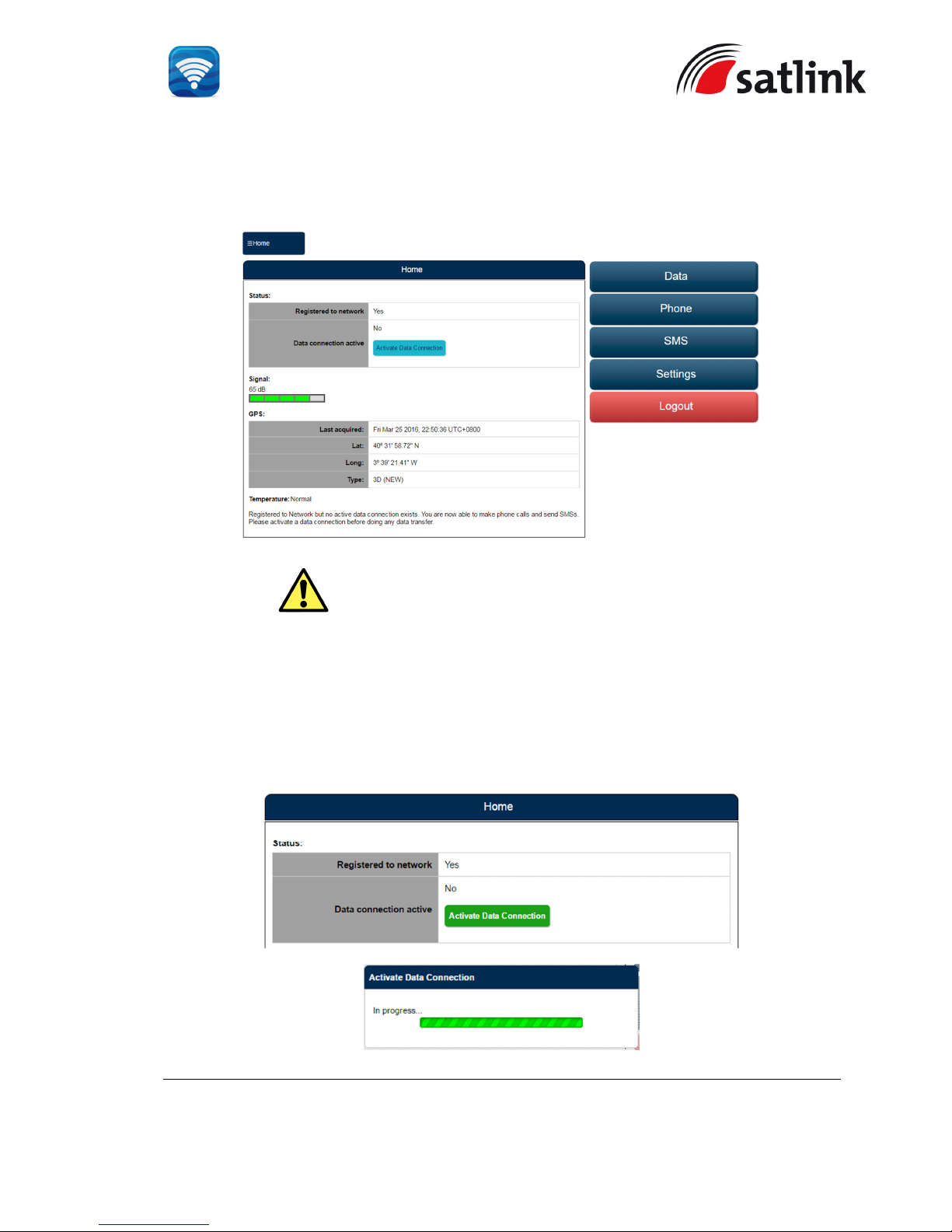
The Web Console will appear. The terminal will proceed automatically to “Checking PIN
status” followed by “Antenna Pointing” and then registering to the network (upon power on).
Upon successful registration, with 3 BDU’s LED indicators (
“TERMINAL”, ”ANTENNA” and
“REGSITERED”
) which are in green, the terminal will be ready for normal operation.
4.3.2 Activating PDP Context
To activate the PDP context for browsing internet, click “Activate Data Connection”. The
BDU’s LED indicator (“DATA ACTIVE”) will turn green.
WARNING: If the signal strength is low (< 50 dB), check any obstruction
against the antenna unit or the condition of antenna cable.
Page 32
SATLINK FLEET ONE Installation Manual Ref: SL00-01191 Ver: 003
Page 32 of 38
Proprietary Information Not To Be Disclosed Without Written Authorisation From
Satlink S.L., All Rights Reserved
4.3.3 Deactivating PDP Context
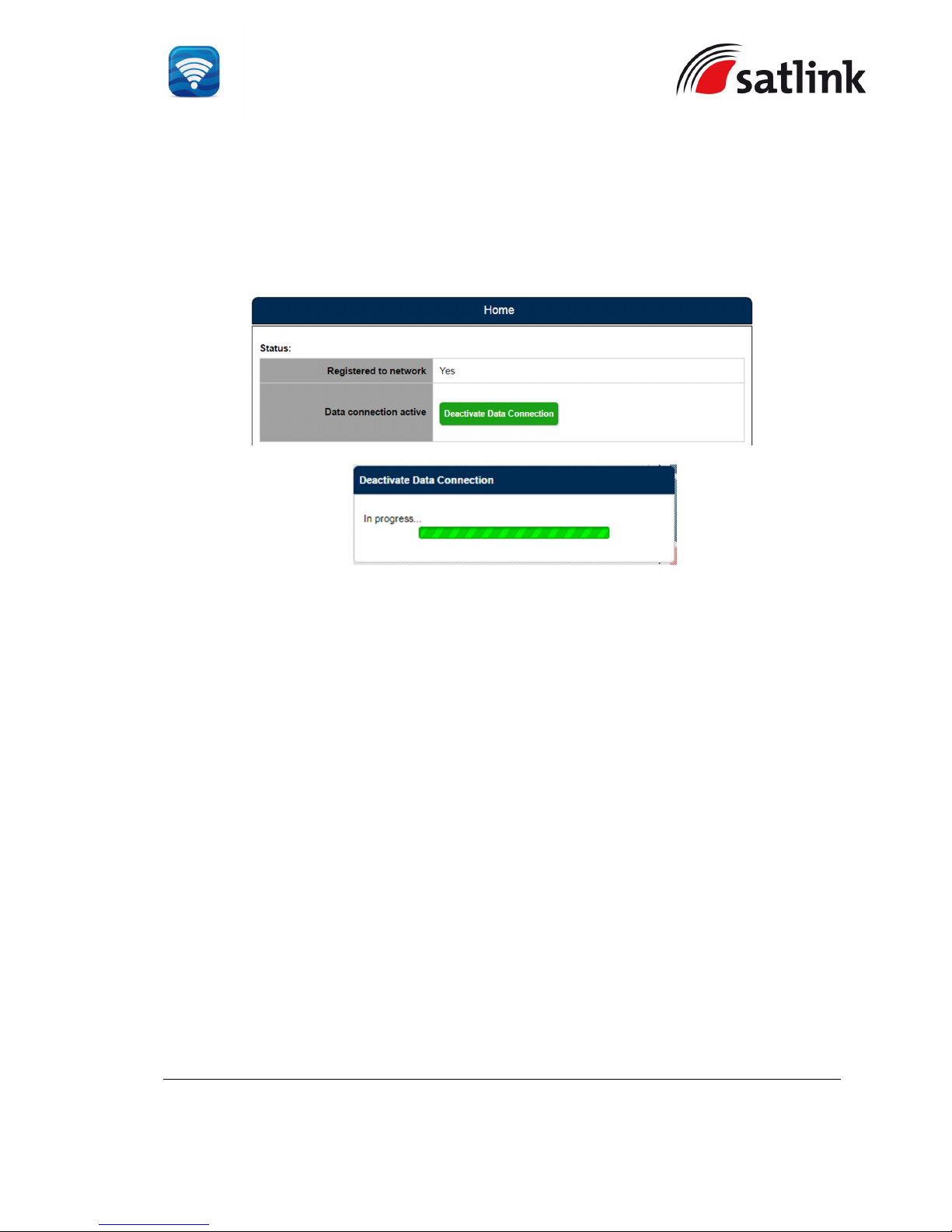
To deactivate the PDP context for browsing internet, click “Deactivate Data Connection”. The
BDU’s LED indicator (“DATA ACTIVE”) will turn off.
Page 33

SATLINK FLEET ONE Installation Manual Ref: SL00-01191 Ver: 003
Page 33 of 38
Proprietary Information Not To Be Disclosed Without Written Authorisation From
Satlink S.L., All Rights Reserved
5 GLOSSARY
AC Alternating Current
ADU Above Decks Unit
APN Access Point Name
BDU Below Decks Unit
DC Direct Current
FTP File Transfer Protocol
GPS Global Position System
GPIO General Purpose Input / Output
IP Data Internet Protocol Data
NAT Network Address Translation
PAT Port Address Translation
PDP Packet Data Protocol
SIM Subscriber Identity Module
VSAT Very Small Aperture Terminal
Page 34
SATLINK FLEET ONE Installation Manual Ref: SL00-01191 Ver: 003
Page 34 of 38
Proprietary Information Not To Be Disclosed Without Written Authorisation From
Satlink S.L., All Rights Reserved
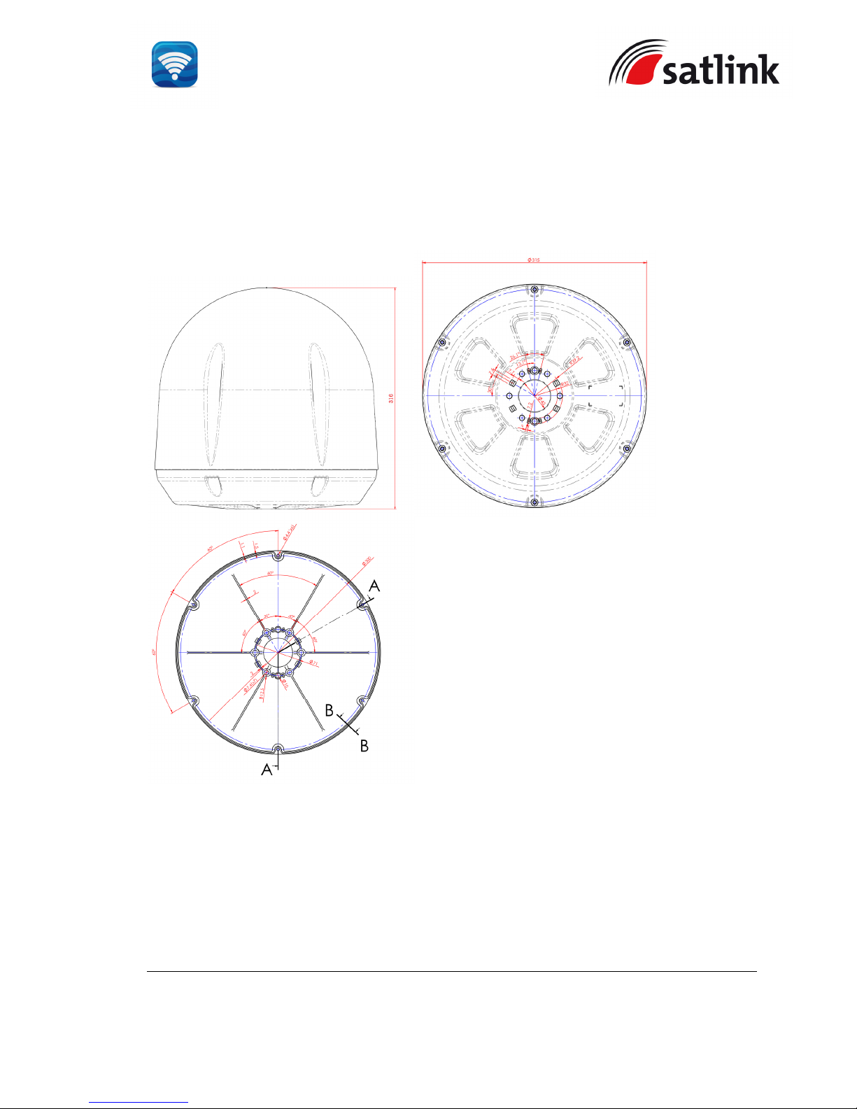
APPENDIX A OUTLINE DRAWINGS
A-1 ADU’s Outline Dimensions and Weight
Weight : 3.55 kg
Dimensions are expressed in terms of mm.
Page 35
SATLINK FLEET ONE Installation Manual Ref: SL00-01191 Ver: 003
Page 35 of 38
Proprietary Information Not To Be Disclosed Without Written Authorisation From
Satlink S.L., All Rights Reserved
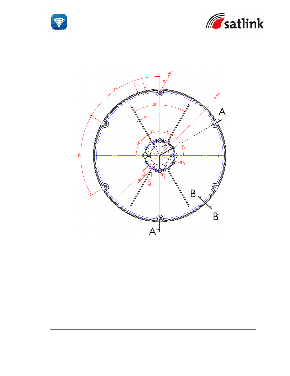
A-2 ADU’s Hole Pattern (Cut-out Holes)
Dimensions are expressed in terms of mm.
Note: Please refer to Satlink document SL00-01132, New radome screw FB250+ before
attempting to open the ADU
Page 36
SATLINK FLEET ONE Installation Manual Ref: SL00-01191 Ver: 001
Page 36 of 38
Proprietary Information Not To Be Disclosed Without Written Authorisation From
Satlink S.L., All Rights Reserved
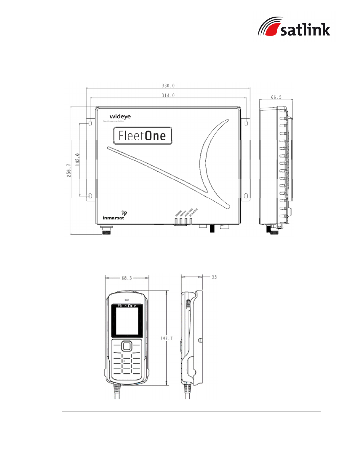
A-3 BDU’s Outline Dimensions
A-4 Primary Handset’s Outline Dimensions
Weight :
3.1kg
Dimensions are expressed in terms of mm.
Weight :
430g (including cradle)
Dimensions are expressed in terms of mm.
Page 37
SATLINK FLEET ONE Installation Manual Ref: SL00-01191 Ver: 001
Page 37 of 38
Proprietary Information Not To Be Disclosed Without Written Authorisation From
Satlink S.L., All Rights Reserved
APPENDIX B GPIO PORT
B-1 Data Connection Switch
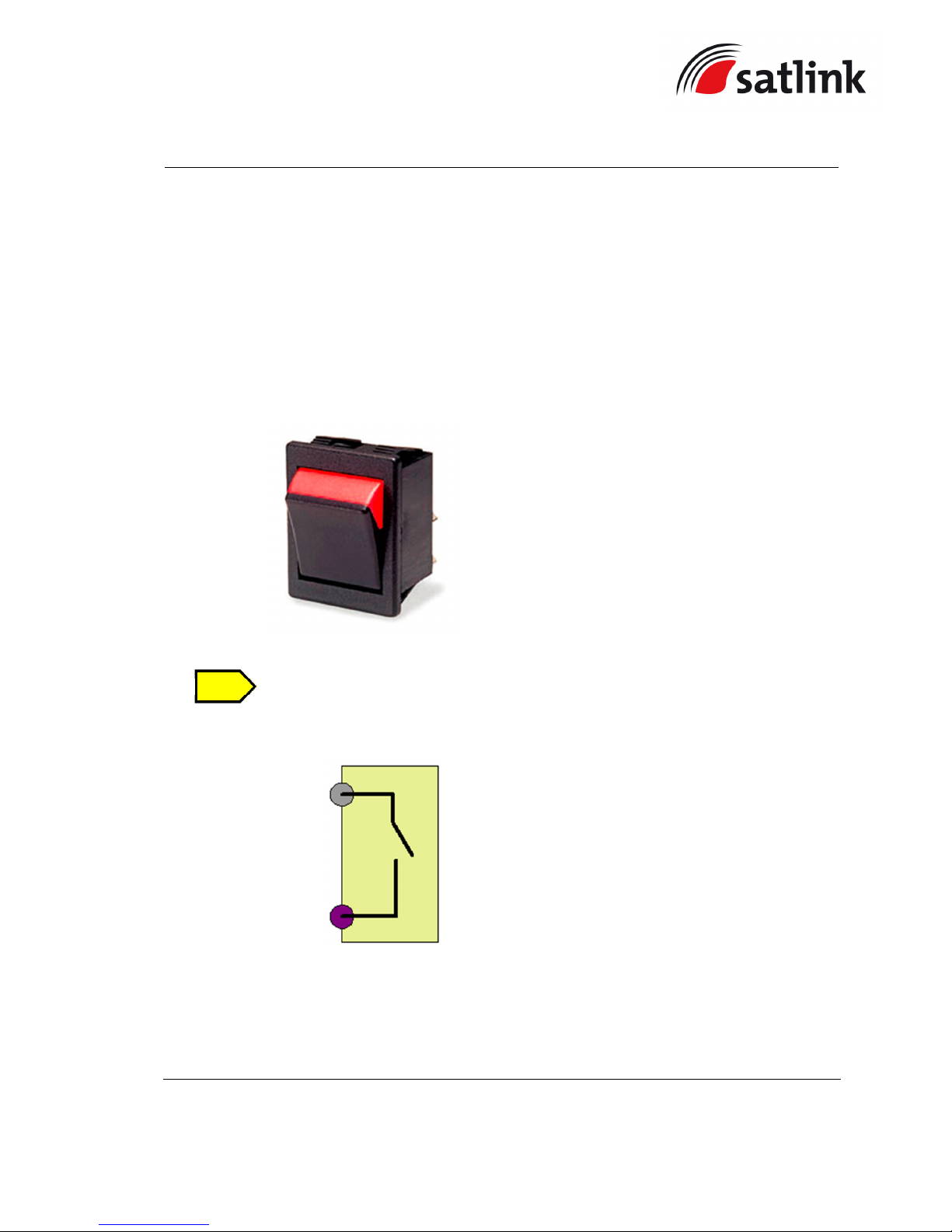
The data connection switch is used for enabling / disabling data connection in the Satlink Fleet
One terminal.
The recommended model and part number of the data connection switch is ACROLECTRIC
SWTICH (P/N: C1350XBAAA), which is a non-illuminated rocker switch.
This item is not included in the packaging list.
The connection diagram is illustrated below:
The steps of the connection are as follow:
1. Solder AWG 24 wires between the rocker switch’s terminal lugs.
2. Mount the rocker switch on the panel according to its cut-out hole dimension.
NOTE
GPIO
- 1
(6V)
GPIO
- 3
(PDP_ON/OFF)
Page 38
SATLINK FLEET ONE Installation Manual Ref: SL00-01191 Ver: 001
Page 38 of 38
Proprietary Information Not To Be Disclosed Without Written Authorisation From
Satlink S.L., All Rights Reserved
3. Connect the other end of these AWG 24 wires to the GPIO Adaptor’s Pin 1 and 3
respectively.
1
3
 Loading...