


expertmeter™
High Performance Analyzer
PM180
SATEC PM180 PLC Configurator
Reference Guide
BG0611 REV.A1

2
Every effort has been made to ensure that the material herein is complete and accurate.
However, the manufacturer is not responsible for any mistakes in printing or faulty
instructions contained in this book. Notification of any errors or misprints will be received
with appreciation.
For further information regarding a particular installation, operation or maintenance of
equipment, contact the manufacturer or your local representative or distributor.
REVISION HISTORY
A1
Jan 2018
Initial release
All trademarks are property of their respective owners
February 2018
Copyright 2017-2018 SATEC Ltd.

3
Table of Contents
1 GENERAL........................................................................................................... 5
2 IEC61131 IMPLEMENTATION ........................................................................... 6
2.1 Limitations.............................................................................................................................. 6
2.2 Data types.............................................................................................................................. 6
2.3 Built-in functions .................................................................................................................... 7
2.3.1 AND ................................................................................................................... 7
2.3.2 OR ..................................................................................................................... 7
2.3.3 NOT ................................................................................................................... 7
2.3.4 GE...................................................................................................................... 8
2.3.5 EQ...................................................................................................................... 8
2.3.6 LE 8
2.3.7 GE_THRESHOLD .................................................................................................. 8
2.3.8 LE_THRESHOLD ................................................................................................... 8
2.3.9 TON ................................................................................................................... 9
2.3.10 TOF ............................................................................................................. 9
2.4 Function block ....................................................................................................................... 9
2.5 Implemented languages ........................................................................................................ 9
2.5.1 Functional block diagram .................................................................................... 10
2.5.2 Ladder diagram.................................................................................................. 10
3 PROGRAMMING GUIDE .................................................................................. 13
3.1 Getting started .....................................................................................................................13
3.2 Creating project ...................................................................................................................13
3.3 Adding devices ....................................................................................................................15
3.4 Device properties .................................................................................................................16
3.5 Main function block ..............................................................................................................17
3.6 Adding function blocks .........................................................................................................17
3.7 Setting function blocks .........................................................................................................18
3.7.1 Rename FB ........................................................................................................ 18
3.7.2 Add variables ..................................................................................................... 19
3.7.3 Variable properties ............................................................................................. 19
3.7.4 Add work area ................................................................................................... 23
3.7.5 Debug FB .......................................................................................................... 23
3.7.6 Delete FB .......................................................................................................... 24
3.8 Communication with the device ...........................................................................................24
3.8.1 Interfaces ......................................................................................................... 24
3.8.2 Upload configuration to the device ....................................................................... 26
3.8.3 Download configuration from the device ................................................................ 29
3.9 Functional block diagrams ...................................................................................................32
3.9.1 Open workspace ................................................................................................ 32
3.9.2 Add or delete variables ....................................................................................... 33
3.9.3 Variable properties ............................................................................................. 34
3.9.4 Add built-in components ..................................................................................... 34
3.9.5 Making connections ............................................................................................ 35
3.9.6 Making time delays ............................................................................................ 37
3.9.7 Programming limits for set point variables ............................................................. 38
3.10 Ladder diagrams ..................................................................................................................41
3.10.1 Add ladder diagram ..................................................................................... 41
3.10.2 Rails .......................................................................................................... 42
3.10.3 Contact ...................................................................................................... 42
3.10.4 Negated contact .......................................................................................... 42
3.10.5 Coil ............................................................................................................ 43
3.10.6 Negated coil................................................................................................ 43

4
3.10.7 Creating LD ................................................................................................ 43
3.10.8 Transformation LD into setpoints ................................................................... 47
3.11 Using PLC Configurator with PAS .......................................................................................47
4 TROUBLESHOOTING ...................................................................................... 49
4.1 Address in not set ................................................................................................................49
4.2 Connection error ..................................................................................................................49
4.3 No MAIN module .................................................................................................................50
4.4 Unconnected inputs .............................................................................................................51

5
1 General
This document specifies a subset of the IEC 61131 standard,
particularly part 3 that deals with the languages used to program
controllers. The document provides complete information necessary to
use SATEC PM180 PLC Configurator (hereinafter referred to as PLC
Configurator) in order to program the PM180 device using Functional
block diagrams (FBD) and Ladder diagrams (LD) and to communicate
with the device. Refer to the PM180 Installation Manual and PM180
Operation Manual for more information on communication connections
and configuring communication parameters in your device.

6
2 IEC61131 Implementation
IEC61131 is the standard relating to programmable controllers. Part 3
of this standard deals with the languages used for programming these
devices and is commonly referred as IEC61131-3. SATEC PM180 PLC
Configurator implements IEC61131-3 in order to create logic for PM180
devices.
IEC 61131-3 support is limited so that programmable controller system
configuration could be compiled to PM180 Setpoints.
2.1 Limitations
Limitations of IEC 61131-3 support are the following:
Programmable controller system configuration is limited to one task
executed at 20ms interval (PM180 hardware limitation). Any
program organization unit could be attached to this task.
Special (nonstandard) *_THRESHOLD functions are used to model
analogue values comparison functions of PM180 Setpoints.
2.2 Data types
Data types implemented in PLC Configurator are listed in the table
below.
Data type
Description
BOOL
Bit string of 1 bit. Logical state, values are FALSE and TRUE.
LREAL
Long real value (64 bit) ±10
±308
,
values are from +/-4.19E-307 to +/-1.67E+308.
TIME
Time duration in milliseconds,
values are from -T#24d20h31m23s648ms to
+T#24d20h31m23s647ms
DATE
Date format, values are from D#1-1-1 to D#65000-12-31,
Gregorian
For the PM180 device refers to the Packed date data type.
TOD
Time of Day format, values are from TOD#00:00:00.000 to
TOD#23:59:59.999
For the PM180 device refers to the Packed time data type.
DT
Date Time format combines DATE and TOD.
For the PM180 device refers to the Timestamp data type.
DP
Double point value. There are four possible values:
intermediate state (IS)
off state (OFF)
on state (ON)
bad state (BS)

7
2.3 Built-in functions
Functions are a type of Program Organization Unit. They are small
reusable units that form the fundamental building blocks of complex
industrial control programs. The implementation contains several builtin functions that are supported by PM180 devices. They are listed in the
table below.
Function
abbreviation
Function name
Inputs
data
type
Outputs
data type
Logical operations
AND
AND
ANY_BIT
ANY_BIT
OR
OR
ANY_BIT
ANY_BIT
NOT
NOT
ANY_BIT
ANY_BIT
GE_THRESHOLD
Greater or equal with threshold
LREAL
BOOL
LE_THRESHOLD
Less or equal with threshold
LREAL
BOOL
GE
Greater or equal
ANY
BOOL
EQ
Equal
ANY
BOOL
LE
Less or equal
ANY
BOOL
Time delays
TON
Timer ON
BOOL,
Time
BOOL
TOF
Timer OFF
BOOL,
Time
BOOL
2.3.1 AND
AND function returns result of all inputs using logical conjunction.
Number of inputs is not limited.
AND function is shown in the figure below.
Figure 1 - AND
2.3.2 OR
OR function returns result of all inputs using logical disjunction. Number
of inputs is not limited.
OR function is shown in the figure below.
Figure 2 - OR
2.3.3 NOT
NOT function returns result of one input using logical inversion.
NOT function is shown in the figure below.

8
Figure 3 - NOT
2.3.4 GE
GE function returns TRUE if input IN1 greater or equal to IN2.
GE function is shown in the figure below.
Figure 4 - GE
2.3.5 EQ
EQ function returns TRUE if input IN1 equal to IN2.
EQ function is shown in the figure below.
Figure 5 - EQ
2.3.6 LE
LE function returns TRUE if input IN1 less or equal to IN2.
LE function is shown in the figure below.
Figure 6 - LE
2.3.7 GE_THRESHOLD
GE_THRESHOLD function returns TRUE if input IN greater or equal to
OPERATE and returns FALSE if input IN less or equal to RELEASE.
In this function IN is a value input, OPERATE and RELEASE are inputs to
set threshold. Usually to set threshold locale variables are used.
GE_THRESHOLD function is shown in the figure below.
Figure 7 - GE_THRESHOLD
2.3.8 LE_THRESHOLD
LE_THRESHOLD function returns TRUE if input IN less or equal to
OPERATE and returns FALSE if input IN greater or equal to RELEASE.
In this function IN is a value input, OPERATE and RELEASE are inputs to
set threshold. Usually to set threshold locale variables are used.

9
LE_THRESHOLD function is shown in the figure below.
Figure 8 - LE_THRESHOLD
2.3.9 TON
TON function is used for making time delays.
TON function returns TRUE if input IN changes from FALSE to TRUE with
the delay set via input PT.
In this function IN is control input (BOOL), input PT is used for setting
time delay in milliseconds.
TON function is shown in the figure below.
Figure 9 - TON
2.3.10 TOF
TOF function is used for making time delays.
TOF function returns FALSE if input IN changes from TRUE to FALSE
with the delay set via input PT.
In this function IN is control input (BOOL), input PT is used for setting
time delay in milliseconds.
TOF function is shown in the figure below.
Figure 10 - TOF
2.4 Function block
Function Block (FB) is a type of Program Organization Unit. It has set of
input variables and output variables. Each block has an algorithm,
which enables evaluation of all its inputs and produces set of output
values. Unlike functions, function blocks also have temporary variables,
which store intermediate values during its evaluation. The execution of
a function block can also depend on its own output in a previous
instance of execution.
Function block can include build-in functions.
2.5 Implemented languages
There are two graphical languages implemented in PLC Configurator:
Function Block Diagram (FBD).
Ladder Diagram (LD).

10
2.5.1 Functional block diagram
Function Block Diagram (FBD) is a programming language defined in
IEC61131-3. FBD is a graphical representation of an Industrial
programmed control system and adopts a set of symbols and
conventions defined in IEC-1131-3. It represents a control system in
terms of signal flow between processing elements similar to the
methodology adopted for signal flow in electronic circuits. By using
interconnected graphical blocks, it expresses the behavior of functions,
function blocks and a composite program.
An example of FBD is shown in the figure below.
Figure 11 – FBD
You can find detailed information about creating FBD in PLC
Configurator in chapter 3.9.
2.5.2 Ladder diagram
Ladder Diagram (LD) is a programming language defined in IEC61131-
3. Ladder diagrams are derived from electrical circuit diagrams, which
have been conventionally used to represent relay logic operations. Many
of the symbols and terminology have also been adopted from the circuit
diagrams. In other words, Ladder Diagrams are graphical
representations of Boolean expressions, but they can also include other
information normally not possible with Boolean expressions.
A ladder diagram has two vertical power rails, one on the left and
another on the right side of the diagram. The left vertical rail carries the
power to the coil (notionally) through the contacts. The contacts are
arranged along horizontal 'rungs' and the power flows through these
rungs to energize the coil, which is on the right hand side of the logic
diagram, when the logic condition represented by the contacts is TRUE

11
(AND logic). Alternative paths can be present with other contacts in
them (in parallel), which can be used to build OR logic.
An example of ladder diagram is shown in the figure below.
Figure 12 - LD
Basic concepts of LD implemented in PLC Configurator are the following:
There are two rails: left rail (so called “+” rail) and right rail (so
called “-” rail).
Between rails can be contacts and one coil. They are situated along
horizontal so called “rung”.
Contacts represent BOOL input variables, whereas coils represent
BOOL output variables.
There are two types of contacts and coils: normally closed and
normally opened.
Serial connection of contacts is used to create AND logic.
Parallel connection of contacts is used to create OR logic.
If all the contacts on the way from the left rail to a coil are closed,
the coil is energized and its state is TRUE.
Coils can have their own contacts like shown in the figure below.

12
Figure 13 – Coil’s contact
To create more complex logic it is possible to add built-in functions
and variables of other from BOOL data types.
Figure 14 - Using TON function in LD
You can find detailed information about creating LD in PLC Configurator
in chapter 3.10.

13
3 Programming guide
3.1 Getting started
Before starting PLC Configurator, be sure you have installed Java 8 64
bit on Windows 7 and above (64 bit versions only).
To start PLC Configurator:
1. Unzip the archive with the application in any folder.
2. Run file “bin/scadastudio.exe”.
3.2 Creating project
To create new project:
1. Start PLC Configurator application.
2. In the application, choose File -> New Project, like shown in the
figure below.
Figure 15 - File menu
3. In the New Project wizard, expand the SATEC category and select
SATEC PLC Project like shown in the figure below. Then click Next.

14
Figure 16 - Project choosing
4. In the Name and Location page of the wizard, do the following (like
shown in the figure below):
In the Project Name field type project name.
To setup project location click on Browse... button or type it in
the Project location field.
Figure 17 - Name and Location
5. Click Finish.
After that the project will be created and opened in PLC Configurator.
You should see the following components:

15
Figure 18 - Created project
3.3 Adding devices
To add new devices do following:
1. Click the right mouse button on the existing project.
Figure 19 - Add device menu
2. Select Device and Language in the “Add a new device” window and
click Ok.
Choose the type of diagram you want to use (Language):

16
FBD (Function Block Diagram).
LD (Ladder Diagram).
Figure 20 - Device properties
After that you will see a newly created device in the project tree.
Figure 21 - Created device in the project
3.4 Device properties
To open device properties double-click on a device in the project tree.
The properties will appear in the middle of the screen:
Figure 22 - Device properties
You can set the following settings:
1. “Release coefficient in comparison operations” – for details see
3.9.7.

17
2. “Settings range for the logic generator” – here you can set the
range of set points that will be used on the PM180 device, during
automatic logic generation. For detailed information see 3.11.
3.5 Main function block
A newly created device contains one function block named MAIN.
Figure 23 - Main function block
Main function block must be in every device. This block is sent to the
device when you use function “Send configuration to the device” (see
3.8.2). If you don’t have main function block in your device you will get
an error (see 4.3).
Note that if you add new function blocks to the device (see 3.6) you
have to use them in the Main function block otherwise that logic will be
ignored during uploading procedure.
3.6 Adding function blocks
To add additional function (FB) block do the following:
1. Click the right mouse button on the section “Programmable logic”
of the device and choose “New function block”.
Figure 24 - Add new function block
2. A new block named “POU” will appear in the project tree.

18
3.7 Setting function blocks
3.7.1 Rename FB
To rename FB click the right mouse button on FB in the project tree and
choose “Rename”.
Figure 25 - Rename FB
Type the new name in appeared window like shown in the figure below
and click OK.
Figure 26 - FB new name
In the following window confirm your action and click Ok.
The FB will be renamed.

19
3.7.2 Add variables
To add variables click the right mouse button on one of the following
sections depending on the type of variable you want to add:
1. Input variables.
2. Output variables.
3. Local variables.
Context menu will appear like shown in the figure below:
Figure 27 - Adding variables
In the menu choose the desired type of variable and click on it with the
left mouse button. A new variable will be added.
You can use the same input or local variable many times on the
same diagram. It can simplify visual perception of your project.
3.7.3 Variable properties
When you click on a variable in a FB tree its properties appear on the
right hand side of PLC Configurator (by default) like shown in the figure
below.

20
Figure 28 - Variable properties
You can set properties using Properties component.
There are following properties:
1. Name – name of a variable.
2. Type – type of a variable. Cannot be changed.
3. Initial value – a value that variable has before it is changed due to
signal flow.
4. Address – mapping variables to the PM180 internal variables such
as digital inputs, relay outputs, set points, etc. Local variables
don’t have such setting.
Please note that in order to operate on the PM180 device every
input and output variable of FB must be mapped to the device internal
variables otherwise you will get a message “Variable address is not set”
during uploading the configuration to the device.
Be advised that PLC Configurator automatically distributes set points
according to the device property “Settings range for the logic
generator”. To set this setting, see 3.4. We discourage you from
mapping output variables to set points, because PLC Configurator does
it automatically anyway. In case of manual mapping output variables to
set points you can get errors concerning execution sequence of function
blocks. In other words, logic that you made in PLC Configurator can be
executed in a different way on the device and the result that you get
will be different.
To set the address, click on icon in the Address setting. Depending
on the type of variable one of the following windows will appear:

21
Figure 29 - Input variables mapping

22
Figure 30 - Output variable mapping
For input variables set an internal device signal that will be a source of
input variable (digital input, relay output, event flag, etc.).
For output signal set an action that will be accomplish when the input
has the proper value.
In any case you should expand desired folder and choose variable you
want to map and then click on Ok.
Please note that you can choose addresses with corresponding type
only, other addresses in the «Setup variable address» are marked in

23
grey color and unavailable for choosing like shown in the figure below.
Variable’s type is shown in the Properties window.
Figure 31 - Variables with unsupported types
The chosen internal variable will appear in the Address setting.
You can rename or delete properties using its context menu.
Figure 32 - Variable context menu
3.7.4 Add work area
To add additional work area click on FB with the right mouse button and
choose one of the following options, depending on the diagram you are
using on the device:
1. Add work area (FBD).
2. Add work area (LD).
New work area will be added and will appear in the FB tree.
3.7.5 Debug FB
Debugger is used if you want to check the logic of FB that you created
or search for mistakes.
To debug FB choose Debug in the context menu of FB. Debugger will
appear like shown in the figure below:

24
Figure 33 - Debugger
You can set input or local variables by clicking on them with the left
mouse button.
When you press button, output values will appear on the lines
corresponding to output variables like shown in the figure below.
Figure 34 - Debug result
3.7.6 Delete FB
To delete FB click on FB with the right mouse button and choose Delete
option. Confirm your action in the following window pressing “OK”. The
FB will be deleted.
3.8 Communication with the device
3.8.1 Interfaces
PCL Configurator supports communication with PM180 device via USB,
Serial port or Ethernet (TCP/IP).
1. To connect via USB you need to plug in USB cable to PM180 USB
port 1.1.
It uses PM180 MODBUS RTU protocol (12 Mb/s) for fast local
communications and data retrieving.

25
2. To connect via Serial port you need to use serial communication
port COM1 with cable suited for RS232/485.
3. Ethernet connection

26
Ethernet connection option is provided by one 10/100TX Ethernet
communication port on the CPU module. Use RJ45 Cable with "Straight
Through" wiring.
3.8.2 Upload configuration to the device
Before you start, need to create a new project or open the existing one.
In addition, your project must contain at least one device and you PC
must be connected to the PM180 device by any of interfaces.
Before uploading PLC Configurator reads current Ration settings from
the device and evaluates constants that are used in the logic you want
to upload.
Please note that you must set all analog values for variables in SI
units only (V, A, W, etc.), otherwise the logic you upload will be working
incorrectly.
To upload configuration from the device do the following:
1. Click the right mouse button on a device and select “Send
configuration to the device” from padding menu.

27
Figure 35 - Context menu
2. After that you will see the upload page.
Figure 36 – Internet site settings
There are 3 types of communication interfaces.
1. Internet site
To upload using TCP/IP you have to select Internet site radio
button and type in address like this:
IP address:Port
Also you have to know a Slave ID of your destination device.

28
2. Serial Port
To upload via Serial port you need to select Serial port radio button
and set properties to meet the serial port settings of the PM810
device.
Figure 37 – Serial port settings
3. USB port
To upload via USB port you need to select USB port radio button and
type in “Slave ID” of the PM180 device.
Figure 38 - USB port settings
After that, your project will be built and you will see the log page:

29
Figure 39 - Building log
In case of successful uploading you will see “Loading complete”
message in the right bottom corner of the application.
3.8.3 Download configuration from the device
Before you start, you need to create a new project or open the existing
one. In addition, your project must contain at least one device and you
must be connected to the PM180 device by any of interfaces.
To download configuration from a device do the following.
Click the right mouse button on a device and select “Import
configuration from the device” from padding menu.
Figure 40 - Import menu
After that you will see the download page.

30
Figure 41 - Internet page
There are three types of communication interfaces.
1. Internet site
To download via TCP/IP you need to select Internet site radio
button and type in address like this:
IP address:Port
Also you have to know a Slave ID of your destination device.
2. Serial port
To download via Serial port you need to select Serial port radio
button and configure properties to meet the settings.

31
Figure 42 - Serial port
3. USB port
To download via USB port you need to select USB port radio button
and type in “Slave ID” of the PM180 device.
Figure 43 - USB port
After that you will see the log page:

32
Figure 44 - Log page
In case of successful downloading you will see “Loading complete” in
the right bottom corner of the application.
Be advised that the graphical form of the algorithm reconstructed
from the device setpoints reflect the logic of the algorithm, however the
visual display representation may be different from the original one.
3.9 Functional block diagrams
See chapters 2.4 and 2.5.1 of this document to get information about
implementation of function blocks and functional block diagrams in PLC
Configurator.
3.9.1 Open workspace
To start creation of FBD you need to open FBD workspace. To do that,
use double-click on workspace section of FB. Workspace will appear in
the middle of the screen like shown in the figure below.
33
Figure 45 - Workspace
3.9.2 Add or delete variables
Before you start to add variables on the workspace, you should add
them to the FB. To do that, see 3.7.2.
To add variable, just drag and drop it to the workspace.
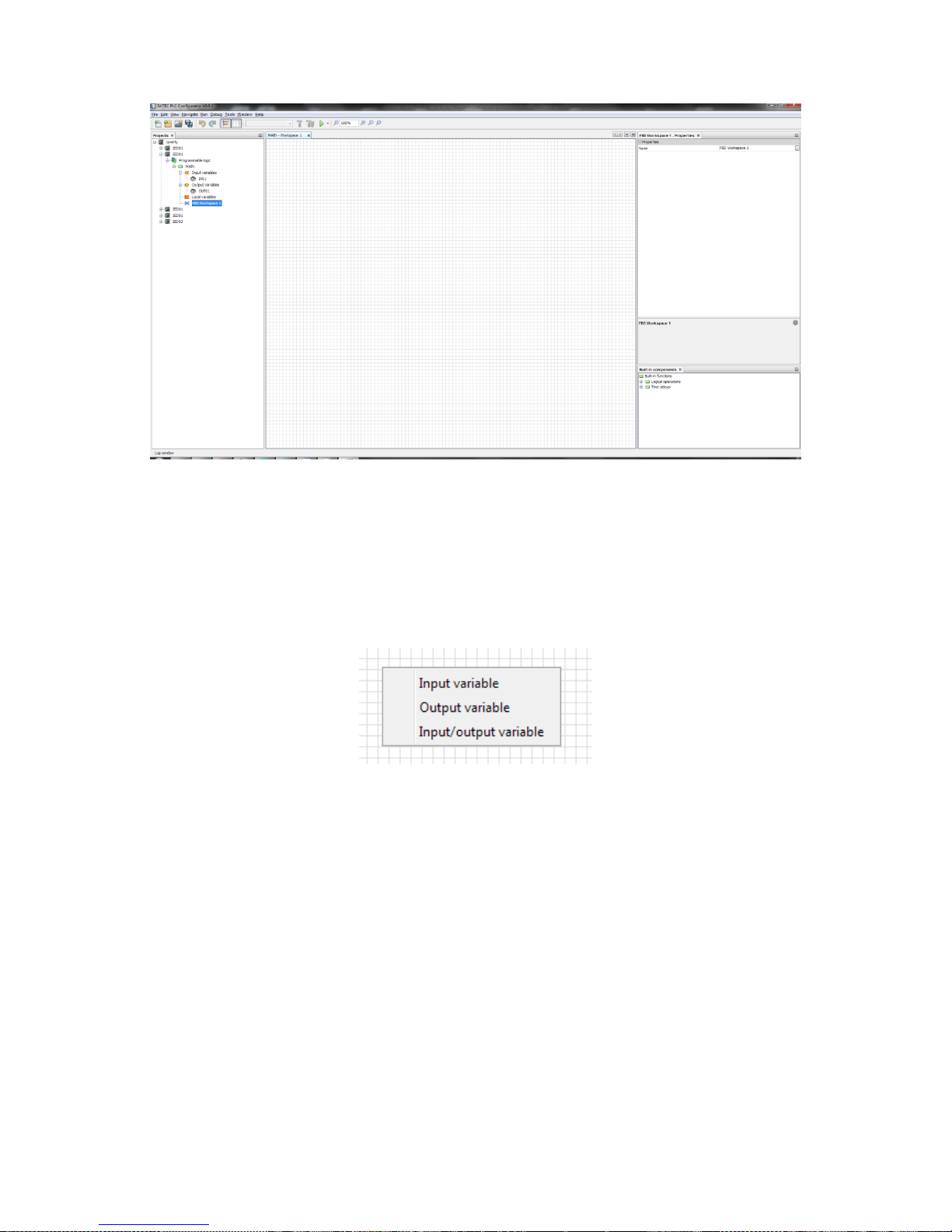
In case of local variable you will get a menu where you need to choose
its type (input, output or input/output variable) like shown in the figure
below.
Figure 46 Type of a local variable
After adding, variables will appear on the workspace.

34
Figure 47 Workspace with variables
To delete variable click on it with the right mouse button and choose
“Delete”.
3.9.3 Variable properties
If you click on a variable that has been added to the workspace, its
properties will appear in the Properties window. They consist of two
parts, like shown in the figure below:
Main properties.
Interface variable properties.
Interface variable properties provide users with the information about
variable’s initial value and address.
3.9.4 Add built-in components
To add built-in functions you need to expand type of function and drag
and drop desired function to the workspace.

35
Figure 48 – Built-in components
After that, components will appear on the workspace.
Figure 49 - Workspace with functions
3.9.5 Making connections
Variables and functions have pins – circles that are used for making
connections. Red pins are not connected, green pins are connected.
Input pins are placed on the left side an element, output pins are placed
on the right side.
To make a connection between a variable and a function, click on an
output pin and drag and drop to the desired input pin.

36
Figure 50 - Connections
If a connection is made the pin will change its color to green and pins
will be linked with an arrow.
Please note that some inputs can be multiple (for example in AND,
OR functions). You can connect unlimited number of inputs there.
Please note that the type of a variable and an input you want to
connect with must be compatible. If they are not, you will not be able to
make a connection between them. You can check type of a pin by
pointing on it with a mouse cursor.
Figure 51 - Pin data type
To disconnect variable click on it with the right mouse button and
choose “Disconnect”.

37
Figure 52 - Disconnect link
After making connections FBD is ready to be uploaded to the device.
Just check that you have set addresses for all variables (see 3.7.3) and
you can proceed to uploading the configuration to the PM180 device
(see 3.8.2).
3.9.6 Making time delays
To make time delays use functions TON and TOF. For detailed
information see 2.3.9 and 2.3.10. Time values are set via local variables
with TIME data type.
Time delay example is shown in the figure below.
Figure 53 - Time delay
Time delay is set in Initial value property in one of these formats (in
accordance with IEC 61131): “T#100ms”, “T#200ms” or “T#1s0ms” (if
a value is more than 1 second).
In the figure below you can see the result of this logic in PAS (after
uploading to the device).

38
Figure 54 - Time delays in PAS
3.9.7 Programming limits for set point variables
There are two standard functions in IEC 61131 that are used for analog
values comparisons: GE and LE. For detailed information about them
see 2.3.4 and 2.3.6.
Be advised that when you use comparison functions you are able to
compare only variables with the same data type (see the figure below).

39
Figure 55 - Comparisons
Limits (particularly release coefficients) aren’t supposed to be used with
these functions. However the PM180 device claims setting these
parameters. To do that, there is a “Release coefficient in comparison
operations” property that you can set via Device properties (see 3.4).
This coefficient has the value range from 0 (exclusively) to 1 (0,95 by
default). When PLC Configurator compiles logic with GE or LE functions,
it multiplies or divides to this coefficient to get operate or release limits.
To set exact (not evaluated) operate or release limits for variables use
functions GE_THRESHOLD and LE_THRESHOLD. For detailed
information about these functions see 2.3.7 and 2.3.8. In this case
limits that are set for these functions compile to operate and release
limits directly.
In the figure below you can see an example of programming limits
using threshold functions.

40
Figure 56 – Using GE_THRESHOLD
In this case limits are set using local variables L01 and L02, IN05 is a
value input.
In the figure below you can see the result setpoint in PAS.
Figure 57 - Setpoint with limits

41
3.10 Ladder diagrams
See chapter 2.5.2 of this document to get basic information about
implementation of ladder diagrams in PLC Configurator.
Basic concepts are similar to creating FBD. We suggest you to read
chapter 3.9 first, then proceed to this chapter.
3.10.1 Add ladder diagram
To create a ladder diagram you need to add a device in your project
and choose LD language in the window shown in the figure below.
Figure 58 - Add new device with LD
If you want to add a ladder diagram to existing function block, just click
with the right mouse button on the function block and choose “Add
work area (LD)”.
Figure 59 - Add work area (LD)
You can use FBD and LD workspaces together in one function block
and divide information between them if it is necessary.
After creating a workspace use double-click on it to open.
A ladder diagram consists of elements such as rails, contacts, coils. Also
it can contain built-in functions (see 2.3).
All elements have pins. Pins can be attached or unattached. Attached
pin are marked as green circle, unattached is marked as red circle.
To add any element to a ladder diagram (excluding rails) you need to
drag-and-drop variable from variables list. Input, output and local
variables are allowed.

42
3.10.2 Rails
There are two power rails: left rail and right rail. Left rail can be
attached to any of variables excluding output variables and to any kind
of coils. Right rail can be attached only to any kind of coils.
Multiple connections are allowed.
You cannot delete rails.
Figure 60 - Rails
3.10.3 Contact
Contact represents a normally open contact. It is closed whenever its
coil or an input which controls it is energized. (Open contact at rest).
It has 2 pins:
Input pin (left pin), that can be attached to left rail output, output
variable, input-output variable, built-in function block contact or
negated contact.
Output pin (right pin) - can be attached to coil, built-in functions,
contact, negated contact or right rail.
Multiple connections are allowed.
Contact can be created from any BOOL variable.
Figure 61 - Contact
3.10.4 Negated contact
Negated contact represents a normally closed ("not") contact. It is
closed whenever its coil or an input which controls it is not energized.
(Closed contact at rest)
It has 2 pins:
Input pin (left pin) - can be attached to left rail output, output
variable, input-output variable, built-in function block contact or
negated contact.
Output pin (right pin) - can be attached to coil, built-in functions,
contact, negated contact or right rail.
Multiple connections are allowed.
Negated contact can be created from any BOOL variable

43
Figure 62 - Negated contact
3.10.5 Coil
Coil represents a normally inactive coil, energized whenever its rung is
closed. (Inactive at rest)
It has 2 pins:
Input pin (left pin) - can be attached to contact, negated contact,
built-in function block, input variable, input-output variable.
Output pin (right pin) – can be attached only to right rail.
Multiple connections are allowed.
Coil can be created only from an output variable or a local variable.
Figure 63 - Coil
3.10.6 Negated coil
Negated coil represents a normally active ("not") coil, energized
whenever its rung is open. (Active at rest)
It has 2 pins:
Input pin (left pin) - can be attached to contact, negated contact,
built-in function block, input variable, input-output variable.
Output pin (right pin) – can be attached only to right rail.
Multiple connections are allowed.
Negated coil can be created only from an output variable or a local
variable.
Figure 64 - Negated coil
3.10.7 Creating LD
Let’s create a simple ladder diagram that contains several contacts and
coils.
To create a contact you need to drag-and-drop a variable to the
workspace.

44
Figure 65 - Add contact
On the appeared menu choose type of the contact, for example
“Normally opened contact”.
Figure 66 – A contact on LD
A contact will be added to a ladder diagram and it will be assigned to
the variable you chose.
Similarly you can add a coil. Just drag and drop an output variable to
the workspace and choose type of the coil you want to add. A coil will
be added to your ladder diagram.

45
Figure 67 - A contact and a coil on LD
Now let’s connect the elements.
To do that, you need to click on the right pin of any element and drag
an arrow from the pin.
Figure 68 - Making connections
Then, drag the arrow to any valid pin, for example, left coil pin.
Now the elements are connected.

46
Figure 69 - Connection made
Let’s finish our rung by connecting other elements.
Figure 70 - A complete rung
Now you can see that when you add more links between rails, the
quantity of pins is being incremented. You are able to make as many
rungs as you like.
Please note that before uploading the configuration to the PM180
device you need to set addresses for all input and output variables. To
do that, see 3.7.3.

47
After that your ladder diagram is ready to be uploaded to the device. To
do that, see 3.8.2.
3.10.8 Transformation LD into setpoints
After uploading you can check the uploaded setpoints in PAS. In the
figure below you can see how a ladder diagram transforms in setpoints
that the PM180 device can use.
Figure 71 - LD logic in PAS
3.11 Using PLC Configurator with PAS
PLC Configurator is only used for setpoints configuration and PAS
should be used for other configuration needs.

48
To create logic on the PM180 devices you can you use PLC Configurator
together with PAS. Some set points can be set via PLC Configurator and
some of them can be set via PAS.
PLC Configurator has a special logic generator which automatically
distributes logic among set points in accordance with a special property
“Settings range for the logic generator” (see 3.4). To set which set
points will be used in this distribution you need to set this property. By
default PLC Configurator uses all set points (1-64). You can set this
range using “-” and “,” symbols like shown in the figure below.
Figure 72 - Settings range
In this case PLC Configurator will be using the first, second set point
and set points between 10 and 16 and between 20 and 30. Other set
points can be programmed via PAS application.

49
4 Troubleshooting
4.1 Address in not set
If you linked a variable on a diagram but didn’t set its address you will
get a message like in the figure below.
Figure 73 - Unknown address
In this case you need to set variables address. To do that, see 3.7.3.
4.2 Connection error
If you have a connection error during uploading or downloading a
configuration you will get a message like shown in the figure below.

50
Figure 74 - Connection error
To fix this you need to press Return and check the communication
interface and connection settings.
You can get proper settings by connecting to the device using PAS
software.
4.3 No MAIN module
“No MAIN module” error appears during building project before
uploading configuration to the device (when you use function “Send
configuration to the device”).

51
In this case you should rename one of the function blocks that are in
the device project or add new function block and set name “MAIN” to it.
4.4 Unconnected inputs
If you get a message like in the figure below, you should check your
FBD for unconnected pins (they are marked as red circles).
Figure 75 – Unconnected inputs error
Figure 76 - Unconnected input
 Loading...