

Page 1
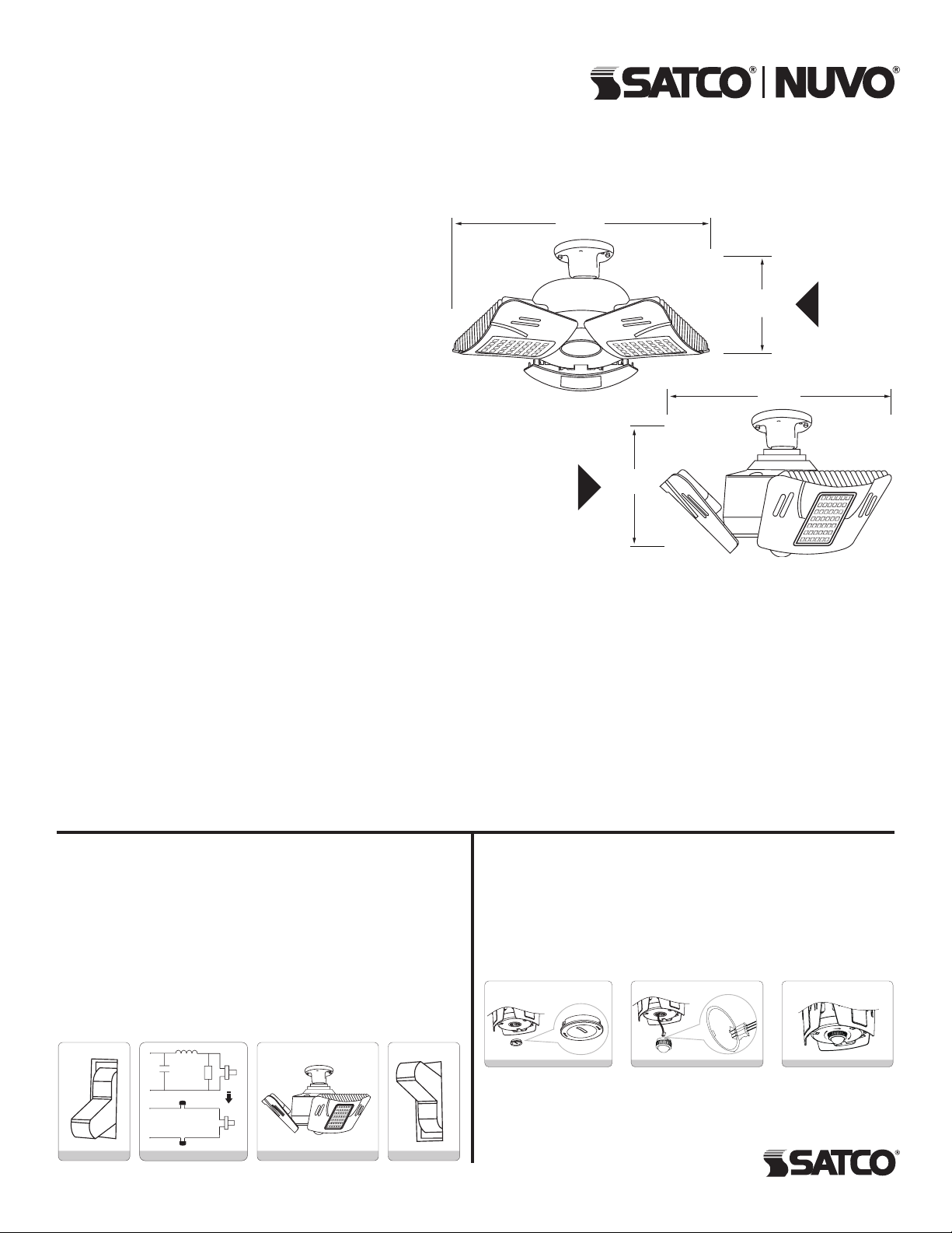
LED HIGH LUMEN UTILITY LAMP
8.63"
Models: S 13118 , S13119
INSTALLATION AND SAFETY INSTRUCTIONS
IMPORTANT: Read before installing xuture. Retain for future reference.
WARNING:
• BEFORE YOU BEGIN: Read these instructions completely
and carefully. To avoid personal injur y and/or product damage,
all of the instructions below must be followed.
• CAUTION: If the lamp or luminaire exhibits undesirable
operation (buzzing, ickering, etc), immediately turn off power,
remove lamp from luminaire and contact the manufacturer or
distributor.
• WARNING: Risk of re or electric shock. LED Retrot Kit
installation requires knowledge of luminaire electrical systems
.If not qualied, do not attempt installation. Contact a qualied
electrician. Installation should be performed only by a qualied
electrician in accordance with Nation Electrical Code and
relevant local code .
• WARNING: Risk of re or electric shock. Install this kit only
in the luminaires that have the construction features and
dimensions written and shown in the photographs and or
drawings and where the input rating of the retrot kit does not
exceed the input rating of luminaire.
• WARNING: To prevent wiring damage or abrasion, do not
expose wiring to edges of sheet metal or other sharp objects.
• Disconnect power at the source before installation, inspection
or removal. Do not simply switch off xture.
• This item is rated at 100-277VAC. Installer must determine
whether line voltage 100-277VAC is available at the luminaire
before installation.
• Not intended for use with emergency exit xtures or
emergency exit lights.
• Not for use with luminaire ballast.
• Do not use if product is damaged.
• This lamp is non-dimmable. Not for use with dimmer.
• Do not make or alter any open holes in an enclosure of wiring
or electrical components during kit installation.
• Risk of re or electric shock . Do not open or modify. No user
serviceable parts inside.
(219.2mm)
Half open
4.33"
(110mm)
4.33"
(110mm)
7.36"
(187mm)
Open
• Installers should not disconnect existing wires from lamp holder
terminals to make new connections at lamp holder terminals.
Instead, installers should cut existing lamp holder leads away from
the lamp holder and make new electrical connections to lamp
holder lead wires by employing applicable connections.
• Suitable for damp locations. Not for use where directly exposed to
the weather or water.
• Complies with part 15 of FCC. Operation is subject to the following
two conditions: This device may not cause harmful interference,
and this device must accept any interference received including
interference that may cause undesired operation.
• No external weight or mechanical force should be applied to lamp
or components.
• The retrot assembly is accepted as a component of a luminaire
where the suitability of the combination shall be determined by UL
or authorities having jurisiction.
INSTALLATION:
STEP 1: Turn off the power to the xture.
STEP 2: Open the xture’s junction box and bypass the HID ballast,
ignitor (if there) and the capacitor (if there) by disconnecting the line
and neutral wires and socket black and white wires in the locations
with “cross” marks in the schematic diagram.Then connect the line to
the black wire from the socket and the neutral to the white wire from
the socket with wire nuts or connectors.
STEP 3: “This luminaire has been modied to operate LED lamps”
shall be marked on the retrot luminaire where readily visible by the
user during normal maintenance including re-lamping.
STEP 4: Turn on the power to the xture.
OFF
STEP 1
X
L
Capacitor
N
LNWire nut
Wire nut
Ballast
Ignitor
X
XX
Lamp socket
STEP 3
ON
STEP 4STEP 2
SENSOR INSTALLATION:
STEP 1: Turn off the power to the xture.
STEP 2: Turn off the Line Cap in arrow reverse direction.
STEP 3: Take out the leadwire and switch in the sensor pins.
STEP 4: Screw and x sensor in arrow direction.
The bulge part of the leadwire must be compatible with the groove
of the sensor.
STEP 3STEP 2STEP 1
Satco Products, Inc.
Br ent woo d, NY 11717© Copyright 2019 Satco Pro ducts, Inc. 12/19
 Loading...