

Satake RMGS 844, RMGS 284 User Manual
INSTRUCTION MANUAL
OPTICAL SORTER 4#
RMGS 284
・
564・844・1404AMS/BM/DMS/AIS/BI/DIS
Type: RMGS1404
0901-27A
r
r
Introduction
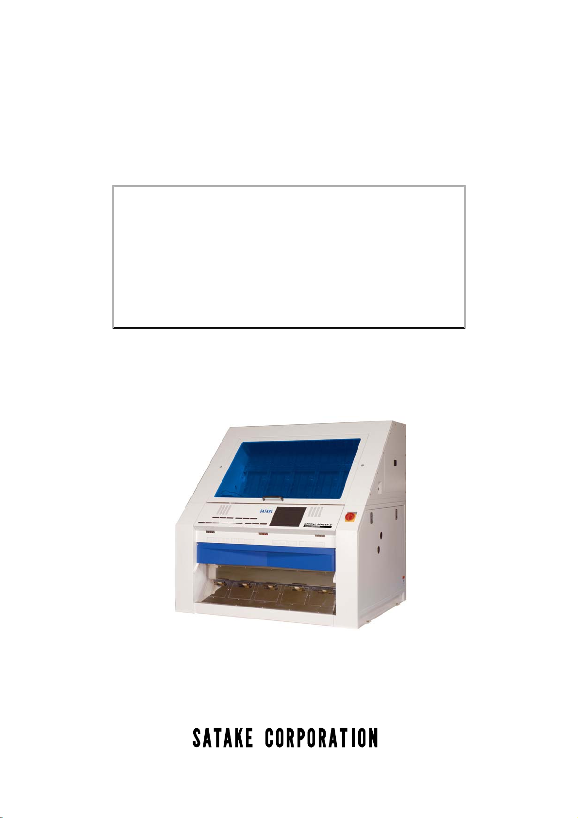
This machine is a Optical Sorter of the chute system which adopts a highly-sensitive camera and can
sort out an accepted grain and a rejected grain with the delicate difference of hue and tone with
sufficient accuracy.In order to fully demonstrate the function and performance of this machine, and also
in order to use regularly for a long time, read this instruction manual throughly. The outline about this
instruction manual is explained below.
For Safety P.1
Make sure to read this instruction manual prior to operation, maintenance and inspection.
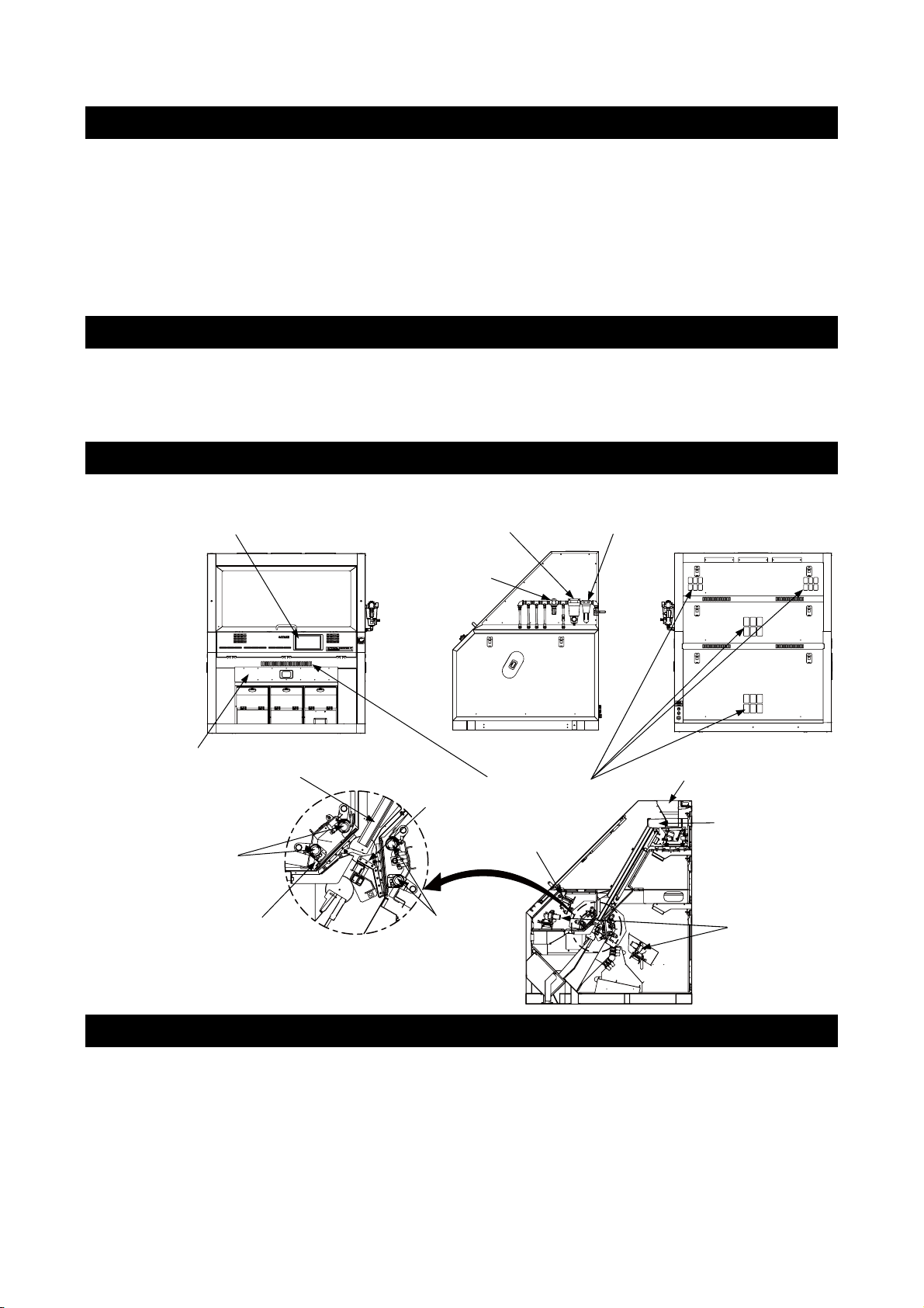
Name and Function of Each Part P.5
Understand the name and function of each part well and operate them.
Touch screen
Dust-collecting
equipment
Fluorescent lamp
Halogen lamp
Chute
Micro mist separato
Regulato
Wiper
NIR camera
Fluorescent
lamp
Suction filter
Air filter
Material tank
Feeder
CCD camera
Mechanism of Machine
The materials thrown in from the material tank are sent out with a feeder, and are supplied to a chute.
The materials which the flow was stabilized with the chute were given up by the optical section are
checked with the upper and lower cameras, and what was distinguished from rejected grains is flown
by the air from an air nozzle at a reject outlet. Adoption of a highly-sensitive camera and a stabilized
supply realize high-precision sorting.
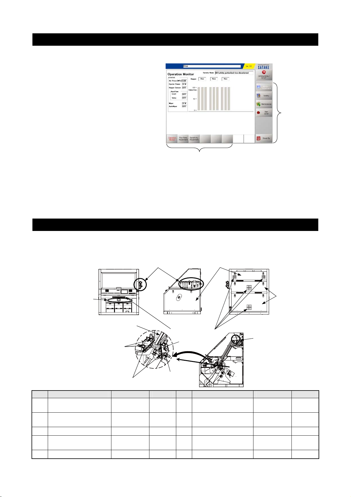
Explanation of Operating Method and Work Procedure P.74
Full explanation of procedure and order of operating methods.
Main menu
Operation Monitor Screen
Sub menu
• Touch “OPERATION/STOP” and the operation starts with selected setting.
• When loading another setting, touch “Variety” of main menu.
• When adjusting each setting, select each icons of main menu. (Main menu has each sub menu.)
• When setting details, access the higher user level on the main menu.
(A password is required to access the higher level.)
• When turning off the power, touch “Stand by” of main menu.
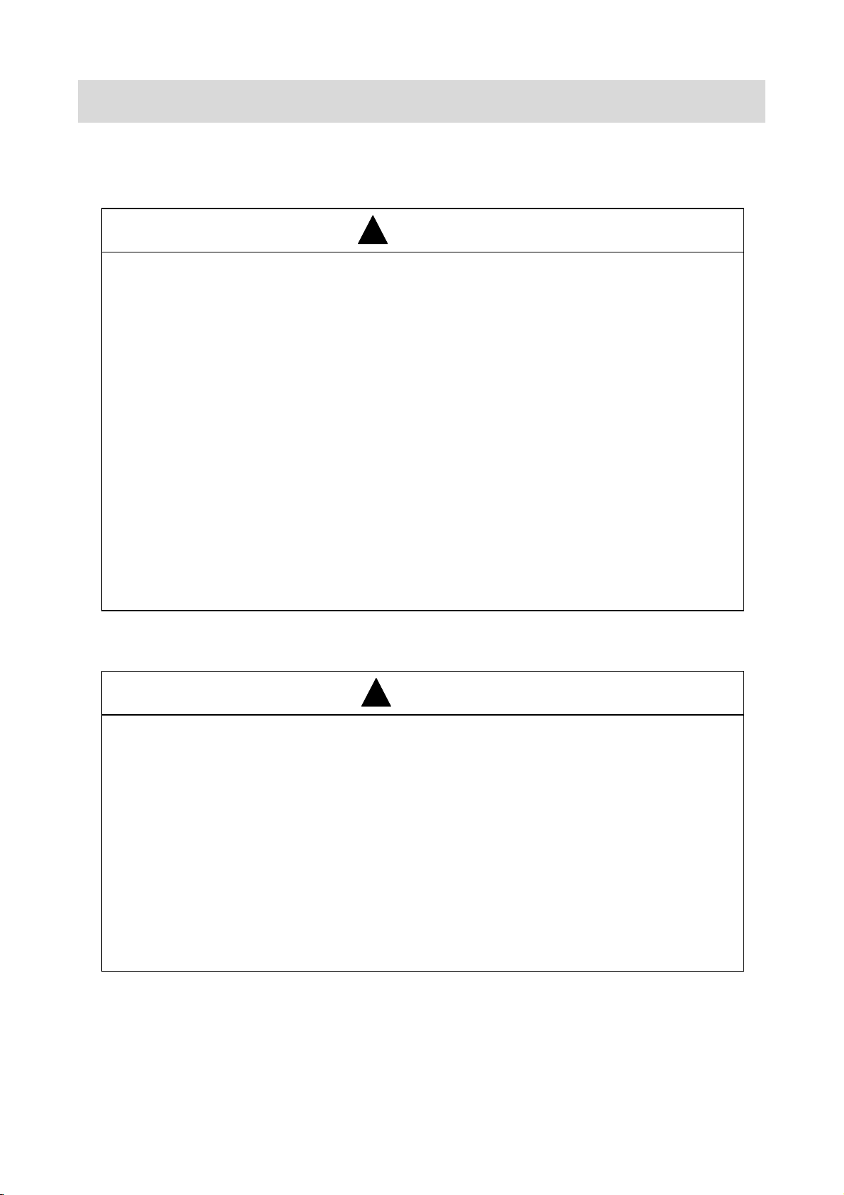
Maintenance and Inspection P.85
In order to demonstrate the function and performance of this machine enough, carry out daily check
and a scheduled inspection certainly, and prevent a trouble
⑨Air filters ②Covers
③Dust-collecting
equipment
②Covers
⑤Fluoresecnt lamp
⑥Chute
⑧Suction filter
④Wiper
⑦Feeder
①Optical section
⑤Fluorescent lamp
No. Action Frequency Ref. No. Action Frequency Ref.
Check dirt in detecting
①
section
Check dust-collecting
③
equipment
Check fluorescent lamp Once a week See P.87
⑤
Check and clean feeder Once a week See P.90
⑦
Check air filter Once a week See P.92
⑨
Once a week See P.85
Once a week
-
Check covers Once a week
②
Check and clean wiper Once a week See P.85
④
Check chute Once a week See P.90
⑥
Check and clean
⑧
suction filters
Daily check Once a day
Once a week See P.91
-
IMPORTANT NOTICE
Specifications and/or machine appearance may change for improvement without notice.
1. For Safety Use:
WARNING
!
(1) Follow this manual when operating, inspecting, or maintaining this machine.
If you have any questions on this machine, contact your local Satake branch office for
answers before operations.
(2) All operating hazards cannot be anticipated regarding this machine. The instructions and
warnings as stipulated in this manual and the warning labels attached on the machine are not
all assumed as hazards. Take special consideration to maintain safe operation. Follow the
instructions and warnings as stipulated in this manual, and heed the warning labels affixed to
this machine.
(3) Do not operate this appliance for any use outside of original design. Operating this machine
outside original parameters can cause accidents to personnel and damage to the machine.
Do not modify the inspection or maintenance schedules.
(4) Operators shall work with managers and superintendents to follow safety procedures and run
the machine in a safe manner.
2. For Instruction Manual:
CAUTION
!
(1) Keep this manual at hand if you have questions about the machine. Contact the local Satake
representative if this manual is lost. Satake would be happy to send a replacement manual.
(2) Illustrations and displays as stipulated in this manual may differ from the actual ones because
they are simplified for easy viewing and understanding by exaggeration or abbreviation.
(3) If you have any questions or errors in this manual, contact the local Satake office.
(4) If this manual is assembled or collated incorrectly, contact the local Satake office to ask for a
correct one. Be sure to inform them of the machine name and model at that time.
(5) If this machine is transferred, or sold to a new owner, make sure this manual stays with the
machine.
i

WARRANTY AND AFTER-SALES SERVICE
1. Limitation of Warranty
<Warranty Clause>
Our equipment is manufactured and supplied under the strict quality control and inspection
guidelines. We warrant that supplied equipment will be free from defects in material and
workmanship for the period of either a) one (1) year from the date of initial start-up operation, or
b) eighteen (18) months from the date of shipment from our shipping port (on the basis of the
Bill of Lading date), whichever is earlier. If any parts or equipment fail to meet the above stated
warranty, we shall supply replacement parts and machines at our own expense provided that any
such failure is clearly proven by the client. The client shall notify us in writing within thirty (30)
days from the date of any such failure. Consumable parts and replacement costs are always
borne by the client, even if the warranty period has not elapsed.
<Limitation Clause>
1. We shall be entirely free from any responsibility and/or liability if product failure is caused
by any of the following:
(1) Misoperation, maintenance and inspection, or negligent treatment of the equipment by
the client and/or user
(2) Any modifications to the design and/or construction, in whole or in part, of the
equipment or any parts therein by the client and/or user
(3) Use outside of normal application and/or abnormal use under overcapacity
(4) Usage of non-genuine parts
(5) Relocation and/or transfer of equipment from the place where initially assembled,
erected constructed and/or installed by the client and/or user
(6) Acts of God, climate, war, warlike hostilities, civil commotion, riots, strikes, fire,
lockouts, plague, or other epidemics, and any other similar circumstances beyond our
control
(7) Any loss or damage to equipment which occurs after shipment of equipment from our
delivery port
2. If this machine is transferred or sold to a new owner, contact the local Satake office.
If Satake is not contacted, Satake will be unable to determine the status of the machine
(maintenance record, installation status) or confirm the existence or non-existence of the
accompanying documents. As a result, the safety and performance of this machine may not
be guaranteed.
2. After-Sales Service
<Limitation of Supply of Spare Parts>
(1) The limitation on the supply of spare parts for the machine is 12 years after production of
the machine is discontinued, though some special parts may be unavailable even if the
limitation period has not elapsed.
(2) The supply of spare parts for this machine will principally finish according to the above
limitation of supply. However, if, after the limitation time has elapsed, the client wishes to
purchase spare parts, Satake may be able to submit a price quotation for the parts desired.
ii

FOR SAFETY
CONTENTS
IMPORTANT NOTICE ............................................................................................. i
WARRANTY AND AFTER-SALES SERVICE......................................................... ii
1 FOR SAFETY........................................................................................................... 1
1.1 Safety Requirements and Caution Warnings................................................. 1
1.1.1 Safety Requirements............................................................................ 1
1.1.2 Prohibition Clause ................................................................................ 1
1.2 Hazards .........................................................................................................2
1.3 Hazard Labels................................................................................................ 2
1.4 Position of Hazard Labels.............................................................................. 3
2 SPECIFICATIONS, DIMENSIONS, AND EXPLANATION OF EACH PART ........... 5
2.1 Specifications................................................................................................. 5
2.2 Dimensions.................................................................................................... 7
2.2.1 RMGS 284 ........................................................................................... 7
2.2.2 RMGS 564 ........................................................................................... 8
2.2.3 RMGS 844 ........................................................................................... 9
AND EXPLANATION OF EACH PART
SPECIFICATION, DIMENSIONS
ASSEMBLY AND
INSTALLATION
EXPLANATION OF
TOUCH PANEL
2.2.4 RMGS 1404 ....................................................................................... 10
2.3 Function of Each Model............................................................................... 11
2.4 Name and Function of Each Part................................................................. 12
3 ASSEMBLY AND INSTALLATION......................................................................... 13
3.1 Caution of Installation .................................................................................. 13
3.2 Dimensions of Inlet, Outlet and Dust-collecting Duct................................... 14
3.2.1 RMGS 284AMS/AIS (Flat 90×2 : U Channel 90×1) ........................... 14
3.2.2 RMGS 284BM/BI (Flat 90×3 : 0) ........................................................ 15
3.2.3 RMGS 564AMS/AIS (Flat 280×1, Flat 90×1 : U Channel 90×2) ........ 16
3.2.4 RMGS 564AMS/AIS (Flat 280×1, Flat 90×2 : U Channel 90×1) ........ 17
3.2.5 GS 564BM/BI (Flat 280×2 : 0)............................................................ 18
3.2.6 RMGS 844AMS/AIS (Flat 280×2 : U Channel 90×3) ......................... 19
3.2.7 RMGS 844AMS/AIS (Flat 280×2, Flat 90×1 : U Channel 90×2) ........ 20
3.2.8 RMGS 844BM/BI (Flat 280×3 : 0) ...................................................... 21
3.2.9 RMGS 1404 AMS/AIS (Flat 280×3 : U Channel 90×6) ...................... 22
3.2.10 RMGS 1404 AMS/AIS (Flat 280×4 : U Channel 90×3) .................... 23
3.2.11 RMGS 1404 DIS
(Flat 280×3 : Flat 280×1, Flat 90×1 : U Channel 90×2)
.24
OPERATION
MAINTENANCE AND
INSPECTION
ELECTRICAL CIRCUITS
TROUBLESHOOTING
3.2.12 RMGS 1404 BM/BI (Flat 280×5 : 0) ................................................. 25
3.3 Space around the Machine.......................................................................... 26

3.4 Welding Guidelines...................................................................................... 26
3.5 Transportation Guidelines............................................................................ 26
3.6 Main Body Installation.................................................................................. 27
3.7 Material Tank and Sample Outlet Installation .............................................. 27
3.8 Air Piping Installation ................................................................................... 28
3.9 Connecting a Power Supply ........................................................................ 32
3.10 Dust Suction Piping Installation ................................................................. 32
3.11 Connecting an External Level Meter Alarm ............................................... 32
3.12 Removing Fixing Brackets Installing the Feeder ....................................... 33
4 EXPLANATION OF TOUCH PANEL ..................................................................... 34
4.1 Title Screen.................................................................................................. 34
4.2 Operation Monitor Screen............................................................................ 35
4.3 Flow Rate Adjustment Screen ..................................................................... 37
4.4 Flow Rate Adjustment (Detail) Screen (User Level 2 and 3) ....................... 38
4.5 Sensitivity Adjustment Screen ..................................................................... 39
4.6 Sensitivity Adjustment (Detail) Screen (User Level 2 and 3) ....................... 40
4.7 Similation Screen (User Level 2 and 3) ....................................................... 42
4.7.1 Capturing the Simulation Image......................................................... 44
4.7.2 Saving the File ................................................................................... 47
4.7.3 Loading the File.................................................................................. 47
4.8 Variety Setting Screen ................................................................................. 48
4.9 Variety List Screen....................................................................................... 49
4.9.1 Saving Present Setting....................................................................... 49
4.9.2 Changing a Saved Variety Name....................................................... 51
4.10 Alarm Monitor Screen (User Level 1) ........................................................ 52
4.11 Alarm Monitor Screen (User Level 2 and 3) .............................................. 52
4.12 Operation Log Screen (User Level 2 and 3) .............................................. 53
4.13 Alarm Log Screen (User Level 2 and 3) .................................................... 53
4.14 Remaining Time, Date/Time Screen (User Level 2 and 3) ........................ 54
4.15 Ejector Remaining Time Screen (User Level 2 and 3) .............................. 55
4.16 Ejector Test Screen (User Level 2 and 3).................................................. 56
4.17 Sorting Mode Screen (User Level 2 and 3) ............................................... 57
4.18 Background Setting Screen (User Level 2 and 3) ..................................... 59
4.19 Auto Flow Setting (by Level) Screen (User Level 2 and 3)........................ 60
4.20 External Communication Screen (User Level 2 and 3).............................. 61
4.21 Signal Processor Setting Screen (User Level 3) ....................................... 62

4.22 Software Update Screen (User Level 2 and 3) .......................................... 64
4.23 Auto Flow Setting (by Ejector) Screen (User Level 3) ............................... 65
4.24 Timer Setting Screen (User Level 3) ......................................................... 67
4.25 Camera Position Screen (User Level 3) .................................................... 68
4.26 Language Screen ......................................................................................69
4.27 Model Selection Screen (User Level 3) ..................................................... 70
4.28 Product Setting 1 Screen (User Level 3) ................................................... 71
4.29 User Level Screen ..................................................................................... 72
5 OPERATION .......................................................................................................... 74
5.1 Operation Adjustment .................................................................................. 74
5.2 Operation Correction ................................................................................... 77
5.2.1 Flow of Rice Grains............................................................................ 77
5.2.2 Adjusting Method of Flow Rate .......................................................... 77
5.2.3 Wiper.................................................................................................. 78
5.2.4 Alarm Monitor..................................................................................... 79
5.2.5 Alarm Cancel...................................................................................... 80
5.2.6 Tank Sensor....................................................................................... 81
5.2.7 Delay and Dwell of Ejector ................................................................. 83
5.2.8 Heater for cold latitudes (Standard kit for brown rice; only in Japan). 84
6 MAINTENANCE AND INSPECTION ..................................................................... 85
6.1 Maintenance and Inspection List ................................................................. 85
6.1.1 Replacement of Fluorescent Lamp and Halogen Lamp..................... 87
6.1.2 Connection of Air Piping..................................................................... 88
6.1.3 Ejector Replacement and Disassembly ............................................. 89
6.1.4 Cleaning of Feeder Trough ................................................................ 90
6.1.5 Chute.................................................................................................. 90
6.1.6 Replacement of Cooling Fan Filter..................................................... 91
6.1.7 Replacement of Filter Element for Micro-Mist Separator ................... 92
<RMGS 284, 564, 844> .......................................................................... 92
6.1.8 Replacement of Air-Filter Element ..................................................... 93
<RMGS 284, 564, 844> .......................................................................... 93
6.1.9 Replacement of Filter Element of Air Filter and Core-Lessing Filter .. 94
<RMGS 1404> ......................................................................................... 94
<Procedure of Replacement of Filter Element> .......................................... 94
6.2 Consumable Parts List................................................................................. 95
6.3 Main Parts List............................................................................................. 97
6.3.1 RMGS 284 ......................................................................................... 97
6.3.2 RMGS 564 ....................................................................................... 100

6.3.3 RMGS 844 ....................................................................................... 103
6.3.4 RMGS 1404 ..................................................................................... 106
7 ELECTRICAL CIRCUITS ..................................................................................... 109
7.1 Wiring Diagram (RMGS 284)..................................................................... 109
7.1.1 Transformer Section......................................................................... 109
7.1.2 Power Supply Unit (Control Circuit) ................................................. 110
7.1.3 Power Supply Unit (Control Power Curcuit 1) .................................. 111
7.1.4 Power Supply Unit (Control Power Curcuit 2) .................................. 112
7.1.5 Signal Processing and Computer..................................................... 113
7.1.6 Fluorescent Lamp ............................................................................ 114
7.1.7 Right Section of the Main body (Feeder Board)............................... 115
7.1.8 Power Supply Unit (Alarm Board) .................................................... 116
7.1.9 Valve Board 1................................................................................... 117
7.2 Wiring Diagram (RMGS 564)..................................................................... 118
7.2.1 Transformer/Breaker Unit................................................................. 118
7.2.2 Power Supply Unit (Control Circuit) ................................................. 119
7.2.3 Power Supply Unit (Valve Power Supply Circuit)............................. 120
7.2.4 Power Supply Unit (Control Power Supply Circuit 1) ....................... 121
7.2.5 Power Supply Unit (Control Power Supply Circuit 2) ....................... 122
7.2.6 Signal Processing and Computer..................................................... 123
7.2.7 Fluorescent Lamp ............................................................................ 124
7.2.8 Right Section of the Main Body........................................................ 125
7.2.9 Power Supply Unit (Alarm Board) .................................................... 126
7.2.10 Valve Board 1, 2, 3......................................................................... 127
7.2.11 Valve Board 4, 5, 6......................................................................... 128
7.3 Wiring Diagram (RMGS 844)..................................................................... 129
7.3.1 Transformer/Breaker Unit................................................................. 129
7.3.2 Power Supply Unit (Control Circuit) ................................................. 130
7.3.3 Power Supply Unit (Valve Power Circuit)......................................... 131
7.3.4 Power Supply Unit (Control Power Curcuit 1) .................................. 132
7.3.5 Power Supply Unit (Control Power Curcuit 2) .................................. 133
7.3.6 Signal Processing and Computer..................................................... 134
7.3.7 Fluorescent Lamp ............................................................................ 135
7.3.8 Main Body Right Section (Feeder Board) ........................................ 136
7.3.9 Power Supply Unit (Alarm Board) .................................................... 137
7.3.10 Valve Board 1, 2, 3......................................................................... 138
7.3.11 Valve Board 4, 5, 6......................................................................... 139
7.3.12 Valve Board 7, 8, 9......................................................................... 140
7.4 Wiring Diagram (RMGS 1404)................................................................... 141

7.4.1 Transformer/Breaker Unit A, Transformer Unit B............................. 141
7.4.2 Power Supply Unit (Control Circuit) ................................................. 142
7.4.3 Power Supply Unit (Valve Power Circuit)......................................... 143
7.4.4 Power Suppy Unit (Control Power Circuit 1) .................................... 144
7.4.5 Power Suppy Unit (Control Power Circuit 2) .................................... 145
7.4.6 Signal Processing and Computer..................................................... 146
7.4.7 Fluorescent Lamp ............................................................................ 147
7.4.8 Right Section of the Main Body (Feeder Board) .............................. 148
7.4.9 Power Supply Unit (Alarm Board) .................................................... 149
7.4.10 Valve Baord 1, 2, 3......................................................................... 150
7.4.11 Valve Board 4, 5, 6......................................................................... 151
7.4.12 Valve Board 7, 8, 9......................................................................... 152
7.4.13 Valve Board 10, 11, 12................................................................... 153
7.4.14 Valve Board 13, 14, 15................................................................... 154
7.5 Transformer and Power Supply Unit (RMGS 284) .................................... 155
7.5.1 Configuration.................................................................................... 155
7.5.2 Transformer and Power Supply Unit Parts....................................... 156
7.6 Transformer and Power Supply Unit (RMGS 564) .................................... 157
7.6.1 Configuration.................................................................................... 157
7.6.2 Transformer and Power Supply Unit Parts....................................... 158
7.7 Transformer and Power Supply Unit (RMGS 844) .................................... 159
7.7.1 Configuration.................................................................................... 159
7.7.2 Transformer and Power Supply Unit Parts....................................... 160
7.8 Transformer and Power Supply Unit (RMGS 1404) .................................. 161
7.8.1 Configuration.................................................................................... 161
7.8.2 Transformer and Power Supply Unit Parts....................................... 162
7.9 Feeder PCB 1, 2 ........................................................................................ 164
7.10 Single Board Computer (SBC)................................................................. 166
7.11 CPU PCB................................................................................................. 167
7.12 Signal Processing PCB............................................................................ 169
7.13 Alarm PCB 1, 2 ........................................................................................ 171
7.14 LED PCB (013P307)................................................................................ 174
7.15 Valve Drive PCB ...................................................................................... 175
7.16 Inverter..................................................................................................... 176
8 TROUBLESHOOTING ......................................................................................... 177
8.1 Troubleshooting List ..................................................................................177

1 FOR SAFETY
This chapter presents a list of safety guidelines to prevent a fatal or serious injury to the operator.
1.1 Safety Requirements and Caution Warnings
The safety guidelines are divided into two sections: requirements for use to ensure operator safety and
caution warnings to prevent accidents.
1.1.1 Safety Requirements
(1) Operator must have hair cut short and wear clothes and shoes that are free of
stray or loose fabric in order to protect from advertent contact with machinery.
Always wear a helmet and safety shoes when carring out any inspection or
maintenance.
(2) Ensure that passages around the machine, as well as surrounding areas, are kept clean at all
times.
(3) Always properly ground the machine in order to protect personnel from fires or electric
accidents caused by current leaks.
(4)
Always inspect the machine before starting operation.
When carrying out any inspection work, always power off and clearly indicate that the machine
is under inspection or maintenance both in the control room and on the control panel.
(5)
Always power off before inspection and maintenance and affix an “Under Inspection” sign over
the power switch. After the inspection, be sure all tools are picked up.
(6)
Check all bolts, nuts, and belts for any looseness or damage.
Be sure to replace all covers after completing this check.
(7) Check for any cuts or damage to power cord, wiring, and cables.
Ensure all connectors and plugs are seated properly.
(8)
Always stop the machine when greasing the driving part of the machine.
(9)
You should get familiarized yourself with the power off procedure for a case of emergency.
(10)
When two or more persons operate the machine, each person must confirm readiness to the
others before starting the machine.
FOR SAFETY
1.1.2 Prohibition Clause
(1) Keep water and other liquids away from the machine. Contact with water or other liquids can
short electric circuits, subsequently causing the machine to break down.
(2) Do not touch any live parts while the machine is powered on.
(3) Do not permit any person other than the individual in charge of machine operation to operate
the machine.
(4)
Keep the operating area clear of any people other than those permitted by the operator.
Never let children near the machine.
(5)
Operate the machine with all covers in place.
Do not attempt to remove any cover while the machine is running.
(6) Do not touch any moving parts while the machine is operating.
(7) Do not put flammable items near the machine.
(8)
Wear a dustproof mask and goggles when operating the machine in a dusty place.
- 1 -
1.2 Hazards
In order to protect workers and prevent damage to processing material, the following two methods are
used to call attention to possible dangers while operating.
(1) A printed warning in this instruction manual
(2) A warning label affixed to the machine
Printed warning and hazard labels are classified into following three levels depending on the degree of
risk or accident at the time of work.
Study these warning signs and always follow the stated instructions.
Warning Word
WARNING
!
CAUTION
!
NOTE
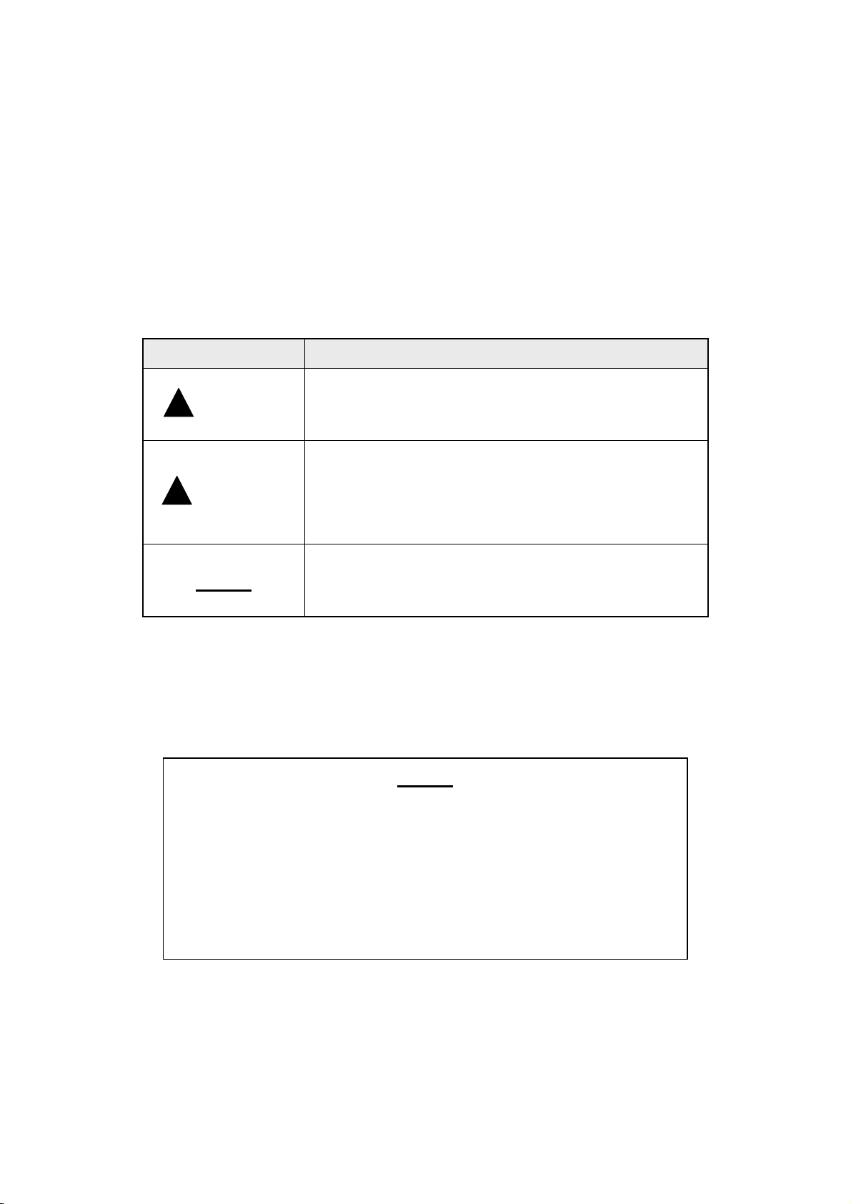
1.3 Hazard Labels
Hazard labels are used to indicate the machine areas/parts requiring special attention.
Be sure to fully understand the content of danger prevention warnings, including the exact positions
and dangers involved.
This shows potential hazard. Failure to follow this warning
increases the possibility of fatal or serious injury.
This shows a potential hazard. Failure to follow this warning
increase the possibility of middle or minor class injury,
damage to equipment or machinery, or trouble with the
material or product.
This warning calls attention to, and places emphasis on,
certain special information.
Definition
NOTE
Handling of Hazard Label
• Be sure all hazard labels can be easily seen and read.
Clean or replace the label if legibile.
• Use cloth, water and detergent to remove the dirt from a hazard label.
Never use organic solvents or gasoline.
• Replace damaged, missing, or unreadable hazard labels with new ones.
- 2 -
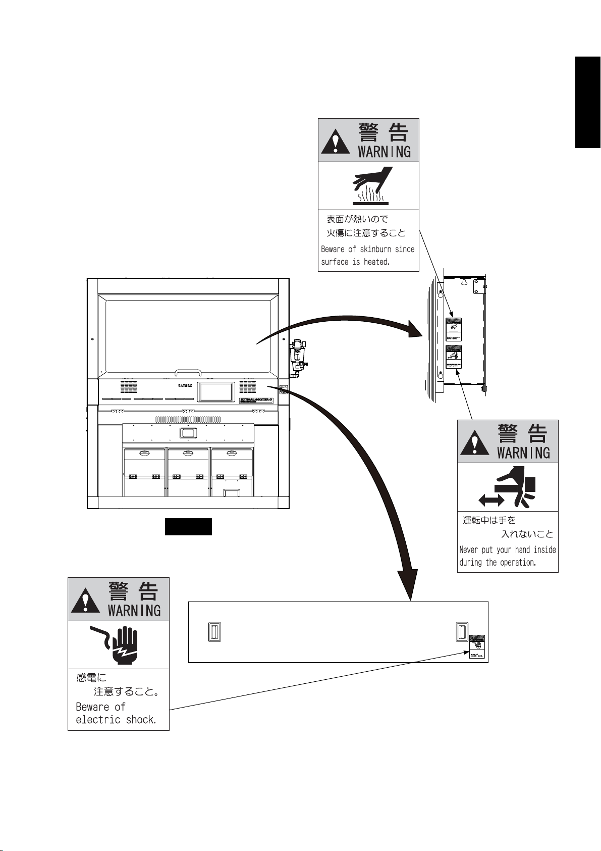
1.4 Position of Hazard Labels
Positions of the following hazzard labels are shown below.
FOR SAFETY
299001511
Front
299001509
299001575
Fig. 1-1 Position of Hazard Labels (1)
- 3 -
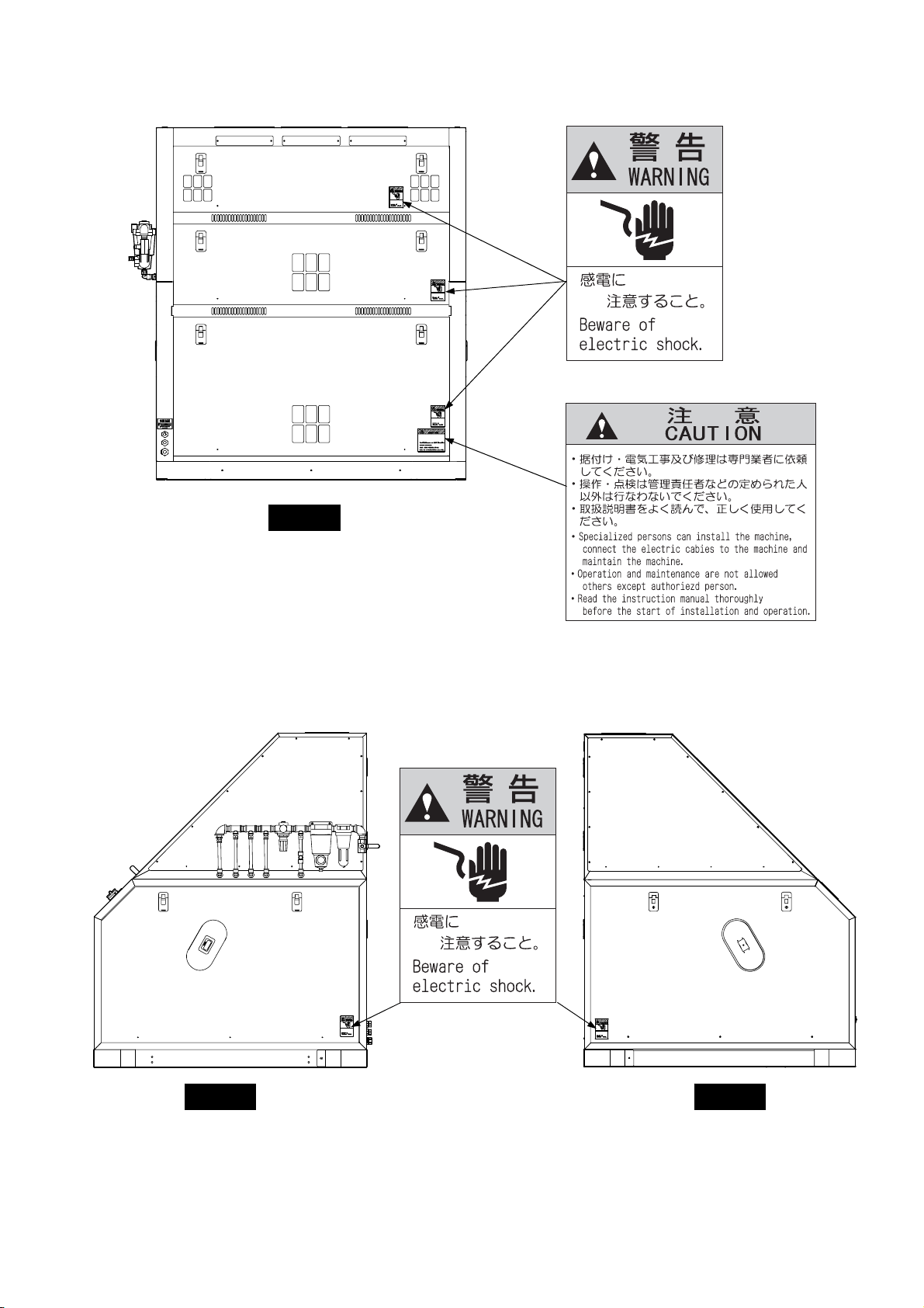
Rear
299001509
299001509
299001535
Left Right
Fig. 1-2 Position of Hazard Labels (2)
- 4 -
2 SPECIFICATIONS, DIMENSIONS, AND EXPLANATION OF EACH PART
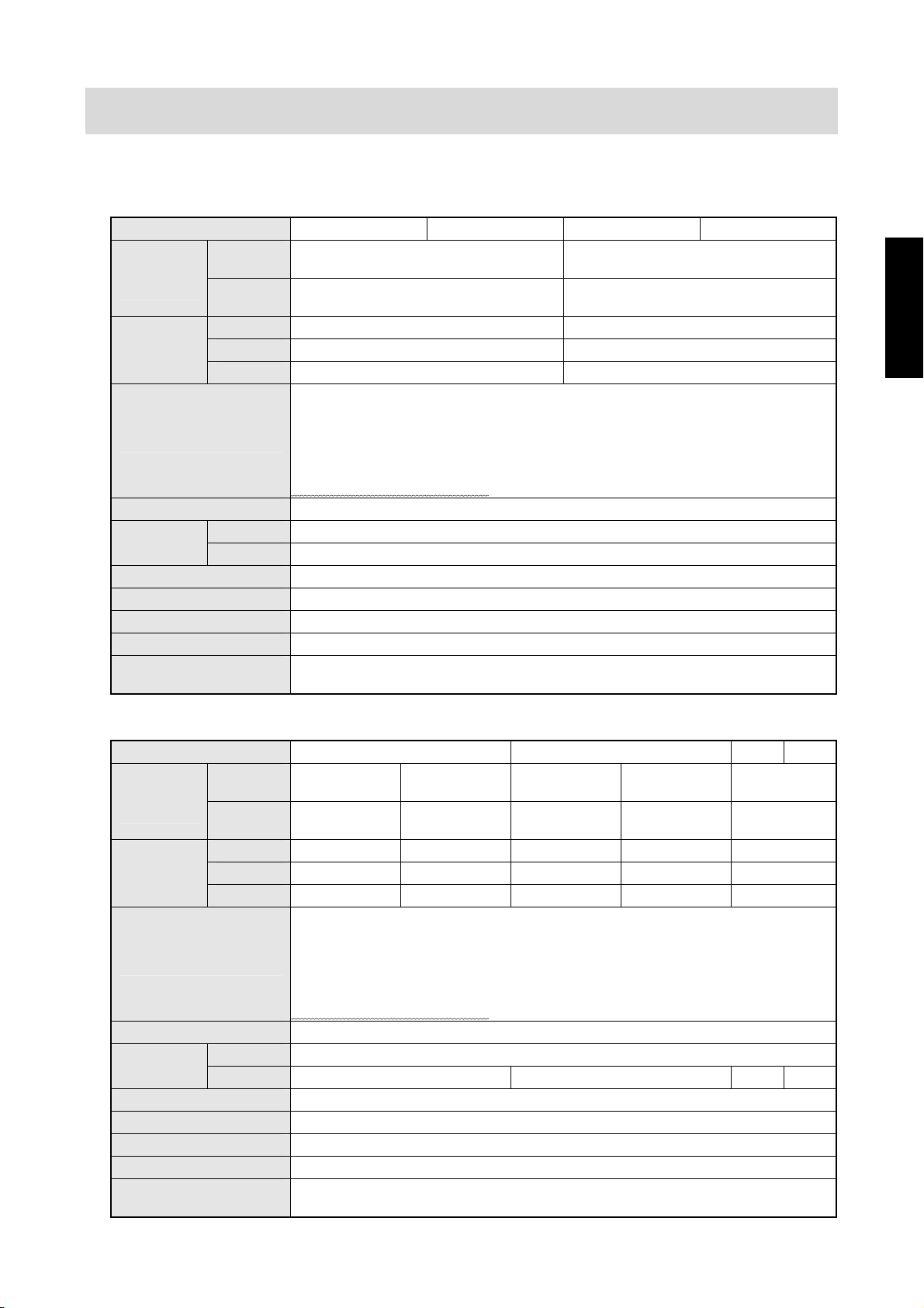
2.1 Specifications
Table 2-1 Specifications List (RMGS 284)
Model AMS AIS BM BI
Primary
Number of
chute
Capacity
(t/h)
Major applications
Power supply (V) Single phase 200
power (kW)
Required air volume 200 ~ 500 NL/min
Dust collector (Optional) 7 m3/min
Compressor (kW) 2.2 ~ 5.5
Net weight (kg) 520
Dimensions (mm)
[Width×Length×Height]
sorting
Secondary
sorting
White rice 0.3 ~ 3.6 0.45 ~ 5.4
Brown rice
Wheat/Barley
Normal 1.2 Required
Maximum 1.7
①Sorting discolored grain in milled rice and brown rice.
②Sorting chalky grain in milled rice and brown rice.
③Sorting discolored and chalky grain in milled rice.
④Sorting discolored grain in wheat and barley.
Sorting inorganic substances (glass, white stone,etc.) in the above-mentioned materials.
⑤
※⑤ is for only AMS and BM.
Flat 90×2 Flat 280×1
U channel 90×1 -
0.3 ~ 1.8 0.45 ~ 2.7
0.3 ~ 1.8 0.45 ~ 2.7
949×1550×1900
AND EXPLANATION OF EACH PART
SPECIFICATIONS, DIMENSIONS
Table 2-2 Specifications List (RMGS 564)
Model AMS AIS BM BI
Primary
Number of
chute
Capacity
(t/h)
Major applications
Power supply (V) Single phase 200
power (kW)
Required air volume 400 ~ 1000 NL/min
Dust collector (Optional) 7 m3/min
Compressor (kW) 3.7 ~ 7.5
Net weight (kg) 700
Dimensions (mm)
[Width×Length×Height]
sorting
Secondary
sorting
White rice 0.75 ~ 9.0 0.6 ~ 7.2 0.75 ~ 9.0 0.6 ~ 7.2 1.35 ~ 16.2
Brown rice
Wheat/Barley
Normal 2.0 Required
Maximum 3.0 2.7 3.0 2.7
Flat 280×1,
Flat 90×2
U channel
90×1
- 0.6 ~ 3.6 - 0.6 ~ 3.6 1.35 ~ 8.1
①Sorting discolored grain in milled rice and brown rice.
②Sorting chalky grain in milled rice and brown rice.
③Sorting discolored and chalky grain in milled rice.
④Sorting discolored grain in wheat and barley.
⑤
※⑤ is for only AMS and BM.
- 0.6 ~ 3.6 - 0.6 ~ 3.6 1.35 ~ 8.1
Sorting inorganic substances (glass, white stone,etc.) in the above-mentioned materials.
Flat 280×1,
Flat 90×1
U channel
90×2
Flat 280×1,
Flat 90×2
U channel
90×1
1309×1550×1900
Flat 280×1,
Flat 90×1
U channel
90×2
Flat 280×2
-
- 5 -
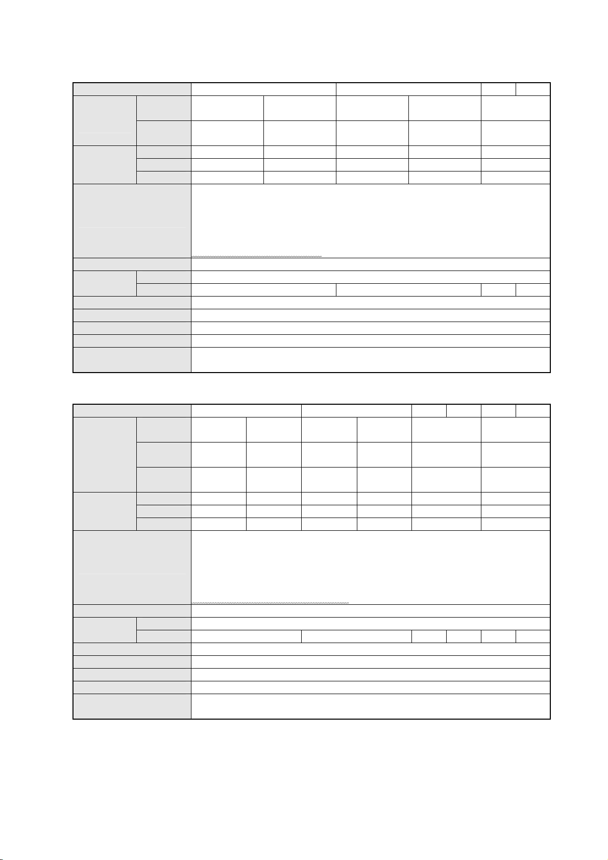
Table 2-3 Specifications List (RMGS 844)
Model AMS AIS BM BI
Primary
Number of
chute
Capacity
(t/h)
Major applications
Power supply (V) Single phase 200
power (kW)
Required air volume 600 ~ 1500 NL/min
Dust collector (Optional) 12 m3/min
Compressor (kW) 5.5 ~ 11.0
Net weight (kg) 920
Dimensions (mm)
[Width×Length×Height]
sorting
Secondary
sorting
White rice 1.05 ~ 12.6 0.9 ~ 10.8 1.05 ~ 12.6 0.9 ~ 10.8 1.35 ~ 16.2
Brown rice
Wheat/Barley
Normal 2.4 Required
Maximum 3.9 3.3 3.9 3.3
Flat 280×2,
Flat 90×1
U channel
90×2
- 0.9 ~ 5.4 - 0.9 ~ 5.4 1.35 ~ 8.1
①Sorting discolored grain in milled rice and brown rice.
②Sorting chalky grain in milled rice and brown rice.
③Sorting discolored and chalky grain in milled rice.
④Sorting discolored grain in wheat and barley.
⑤
※⑤ is for only AMS and BM.
- 0.9 ~ 5.4 - 0.9 ~ 5.4 1.35 ~ 8.1
Sorting inorganic substances (glass, white stone,etc.) in the above-mentioned materials.
Flat 280×2
U channel
90×3
Flat 280×2,
1669×1550×1900
Flat 90×1
U channel
90×2
Flat 280×2 Flat 280×3
U channel
90×3
-
Table 2-4 Specifications List (RMGS 1404)
Model AMS AIS BM BI DMS DIS
Primary
sorting
Number of
chute
Capacity
(t/h)
Major applications
Power supply (V) Single phase 200
power (kW)
Required air volume 1000 ~ 2000 NL/min
Dust collector (Optional) 15 m3/min
Compressor (kW) 7.5 ~ 15.0
Net weight (kg) 1300
Dimensions (mm)
[Width×Length×Height]
Secondary
sorting
Tertiary
sorting
White rice 1.8 ~ 21.6 1.35 ~ 16.2 1.8 ~ 21.6 1.35 ~ 16.2 2.25 ~ 27.0 1.35 ~ 16.2
Brown rice
Wheat/Barley 1.8 ~ 10.8 1.35 ~ 8.1 1.8 ~ 10.8 1.35 ~ 8.1 2.25 ~ 13.5 1.35 ~ 8.1
Normal 4.0 Required
Maximum 6.0 5.4 6.0 5.4 6.0 5.4
Flat
280×4
U channel
90×3
- - - - -
1.8 ~ 10.8 1.35 ~ 8.1 1.8 ~ 10.8 1.35 ~ 8.1 2.25 ~ 13.5 1.35 ~ 8.1
①Sorting discolored grain in milled rice and brown rice.
②Sorting chalky grain in milled rice and brown rice.
③Sorting discolored and chalky grain in milled rice.
④Sorting discolored grain in wheat and barley.
⑤
Sorting inorganic substances (glass, white stone,etc.) in the above-mentioned materials.
※⑤ is for only AMS, BM and DMS.
Flat
280×3
U channel
90×6
Flat
280×4
U channel
90×3
2250×1550×1900
Flat
280×3
U channel
90×6
Flat 280×5 Flat 280×3
-
* Inorganic substances are noncarbon compounds, including stones and glass.
* Capacity depends on material variety and mixing rate of contaminants.
* When processing materials of very high mixture rates of contamination, large volume of
compressed air is required. Be careful of your compressor capacity.
* This machine is without conveyors. The user shall prepare conveyers. (Available as an option.)
* Use the U channel chute if primary sorting volume is 0.45t/h or less.
Flat 280×1,
Flat 90×1
U channel
90×2
- 6 -
2.2 Dimensions
2.2.1 RMGS 284
Unit: mm
949
1550
AND EXPLANATION OF EACH PART
SPECIFICATIONS, DIMENSIONS
1900
Front Right
908
599
126
300 950
Bottom
Fig. 2-1 Dimensions (RMGS 284)
- 7 -
2.2.2 RMGS 564
Unit: mm
1309
1550
1900
Front
Right
1258
959
126
300
950
Bottom
Fig. 2-2 Dimensions (RMGS 564)
- 8 -
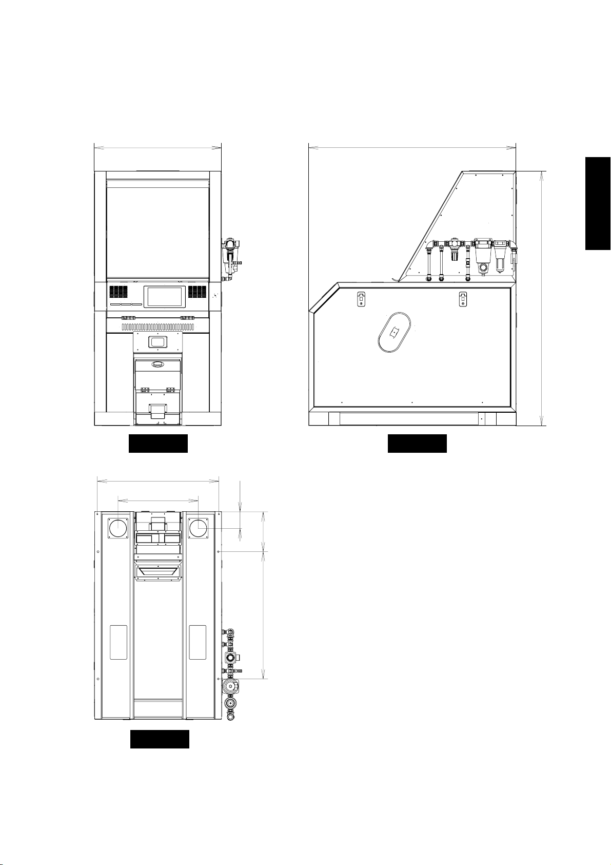
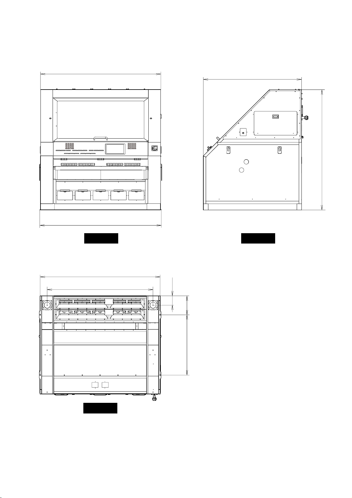
2.2.3 RMGS 844
Unit: mm
1669
1550
AND EXPLANATION OF EACH PART
SPECIFICATIONS, DIMENSIONS
1900
Front
Right
1618
1319
126
300
950
Bottom
Fig. 2-3 Dimensions (RMGS 844)
- 9 -
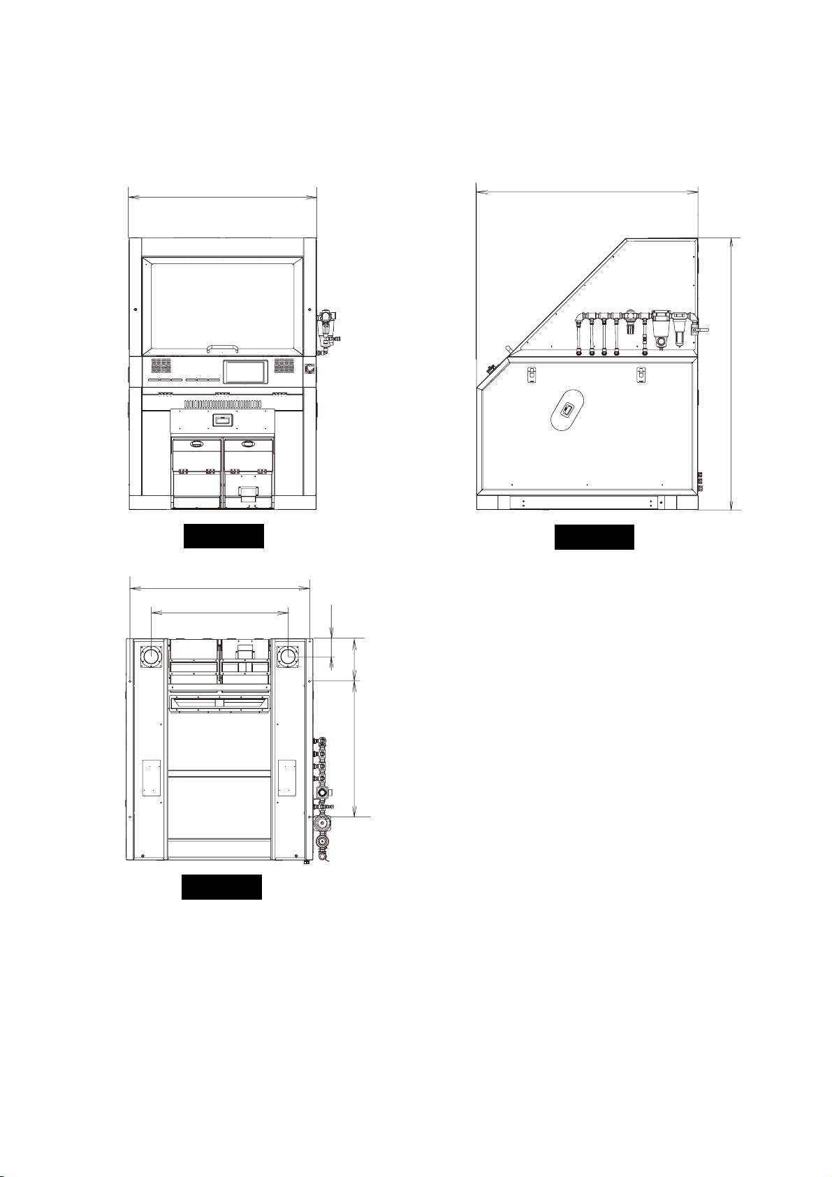
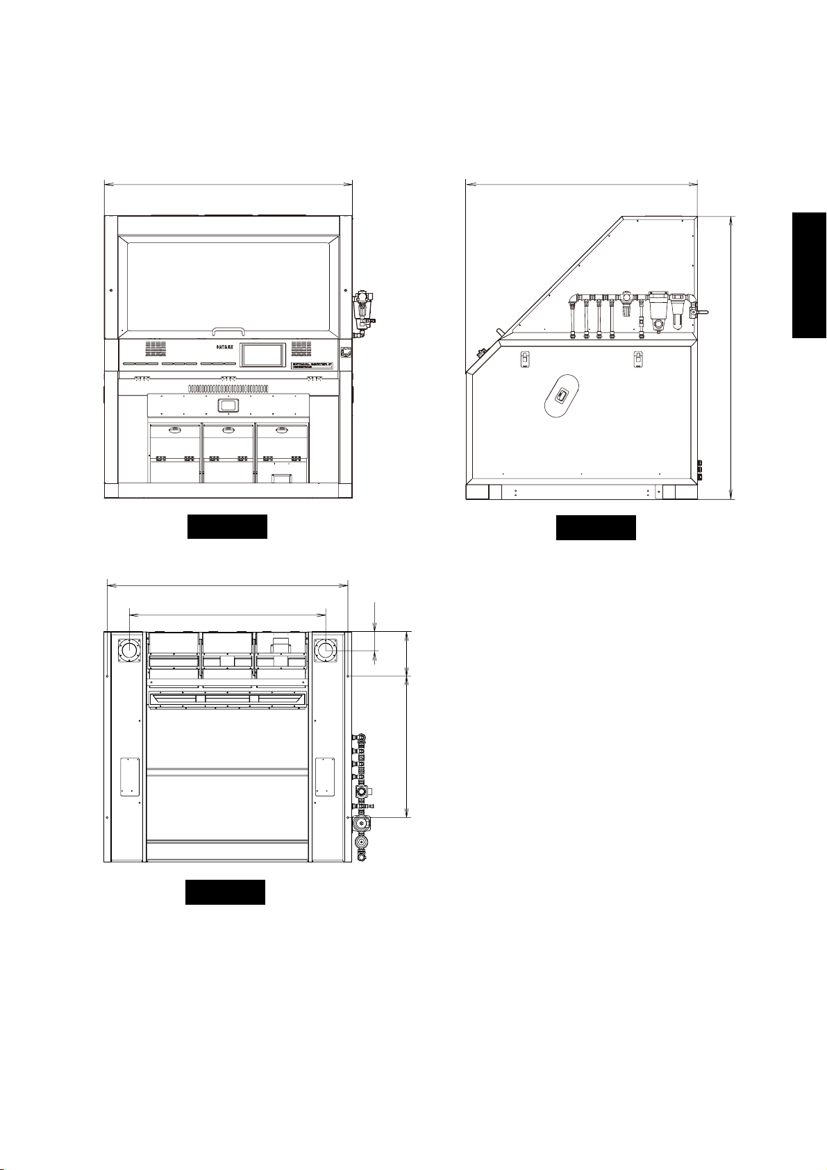
2.2.4 RMGS 1404
Unit: mm
1900
1550
1900
1920
Front
Right
1890
1670
148
300
950
Bottom
Fig. 2-4 Dimensions (RMGS 1404)
- 10 -
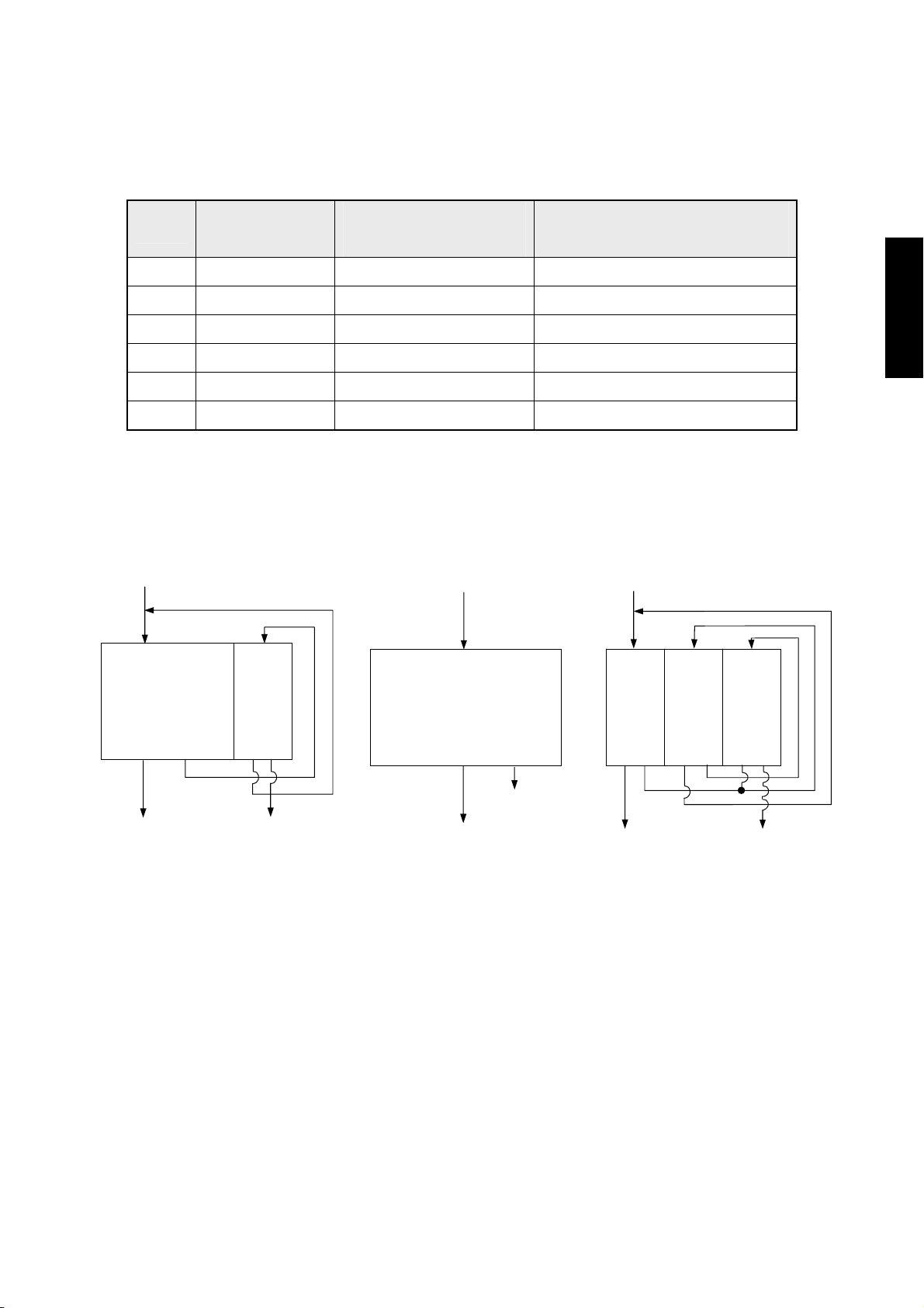
2.3 Function of Each Model
Table 2-5 Function of Each Model
Sorting of Glass
Primary/Secondary
Primary/Secondary/Tertiary
Model
AMS
AIS
BM
BI
DMS
DIS
and Stone
○ ○ ×
× ○ ×
○ × (Only primary sorting) ×
× × (Only primary sorting) ×
○ × ○
× × ○
Sorting
Sorting
<AMS/AIS> <BM/BI> <DMS/DIS>
Material
Material
Material
AND EXPLANATION OF EACH PART
SPECIFICATIONS, DIMENSIONS
Primary
sorting
Product
Secondary
sorting
Primary reject
Final reject
Secondary accept
Fig. 2-5 Function of Each Model
Primary sorting
Final reject
Product
Primary
sorting
Primary reject
Product
Secondary
sorting
Secondary reject
Tertiary accept
Secondary accept
Tertiary
sorting
Final reject
- 11 -
r
r
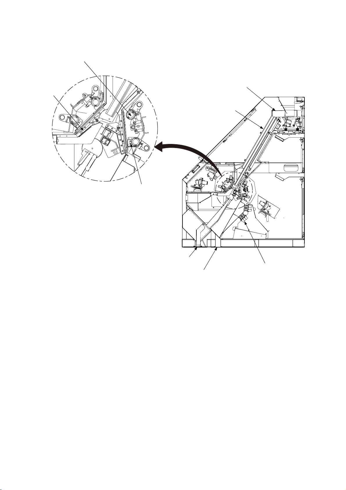
2.4 Name and Function of Each Part
Fluorescent lamp
Wipe
Feede
Chute
Halogen lamp
Accept outlet
Ejector valve
Reject outlet
Fig. 2-6 Structure (Side Surface)
Material is continuously supplied through the intake hopper and feeder, and the flow is rectified by the
chute.
The rectified flow of rice grains enters the optical section at a constant rate.
The optical section is illuminated by four fluorescent lamps and halogen lamps placed on the front and
rear sides. The fluorescent lamp is the light source to sort any discolored and chalky grains and the
halogen lamp is the light source to sort glass, stone and plastics in the grain.
Rice passing through the optical section is observed from both front and rear sides.
When any discolored grains, chalky grain, glass, stone and plastic materials (rejects) are detected by the
reflected or passed light.
They are blown off by the air jet from the ejector to the outside of the accept outlet (reject outlet).
The wiper is provided to keep the anti-dust glass screen clean for the consistent sorting function.
- 12 -

A
3 ASSEMBLY AND INSTALLATION
!
• Wrong choice of the location for installation may cause injuries.
3.1 Caution of Installation
(1) Place the machine horizontally.
The machine should be installed on the level surface.
(2) Install the machine at a vibration-free place.
When installing the machine on a common base together with other machines, special attention
should be paid to the strength of the base. And when mounting a large hopper tank on top of the
machine, avoid attaching it directly to the machine itself to prevent adverse effects by the vibration
WARNING
INSTALLATION
SSEMBLY AND
caused by the down flow of materials. Strong vibrations will cause the down flow of materials
through the feeder while the machine is not operation, or cause poor contact in the electrical
connections.
(3) Avoid the influences of sunlight and illumination.
If strong lights directly enter the optical section by the passage of time, the brightness in the optical
section will fluctuate which may induce failures in sorting operation. When installing the machine
near the windows facing south, a proper measure should be taken to avoid the fluctuation of
brightness. In addition, pay attention not to allow light from fluorescent lamps or mercury lamps to
enter the detecting section because it may cause malfunction.
(4) On ambient temperature, humidity, dust and other environmental factors.
Operating ambient temperature range is 0℃ to 40℃. Avoid to install the machine on the location
where it is humid, hot, or dusty. Install a heater for cold district of option when the ambient
temperature becomes below 10℃. In case that the ambient temperature arounf the machine exceeds
the specified range, install the air conditioner.
(5) Avoid to install the sorter on the process next following the rice milling.
It must be installed on the process coming just after grain size selection.The chute is likely to collect
bran immediately after the rice milling, or in winter. Ideally, it should be placed after the cooling
process. If the bran still adheres to the chute, turn on the heater switch. In case of brown rice sorting,
keep temperature difference between brown rice and outside less than 5℃. If brown rice stored in
low temperature is sorted directly, condensation on the surface of brown rice causes bran adhesion
in brown rice tank and on chute, there is a possibility of having a bad influence on sorting
performance. In this case, use chute heater unit for brown rice of option.If the sorter is installed after
the process of removing the broken grain or bran, it will not only minimize failures but improve
efficiency. Rotary sifter and white rice grading machine should be installed in the process preceding
to the new color sorter.
- 13 -
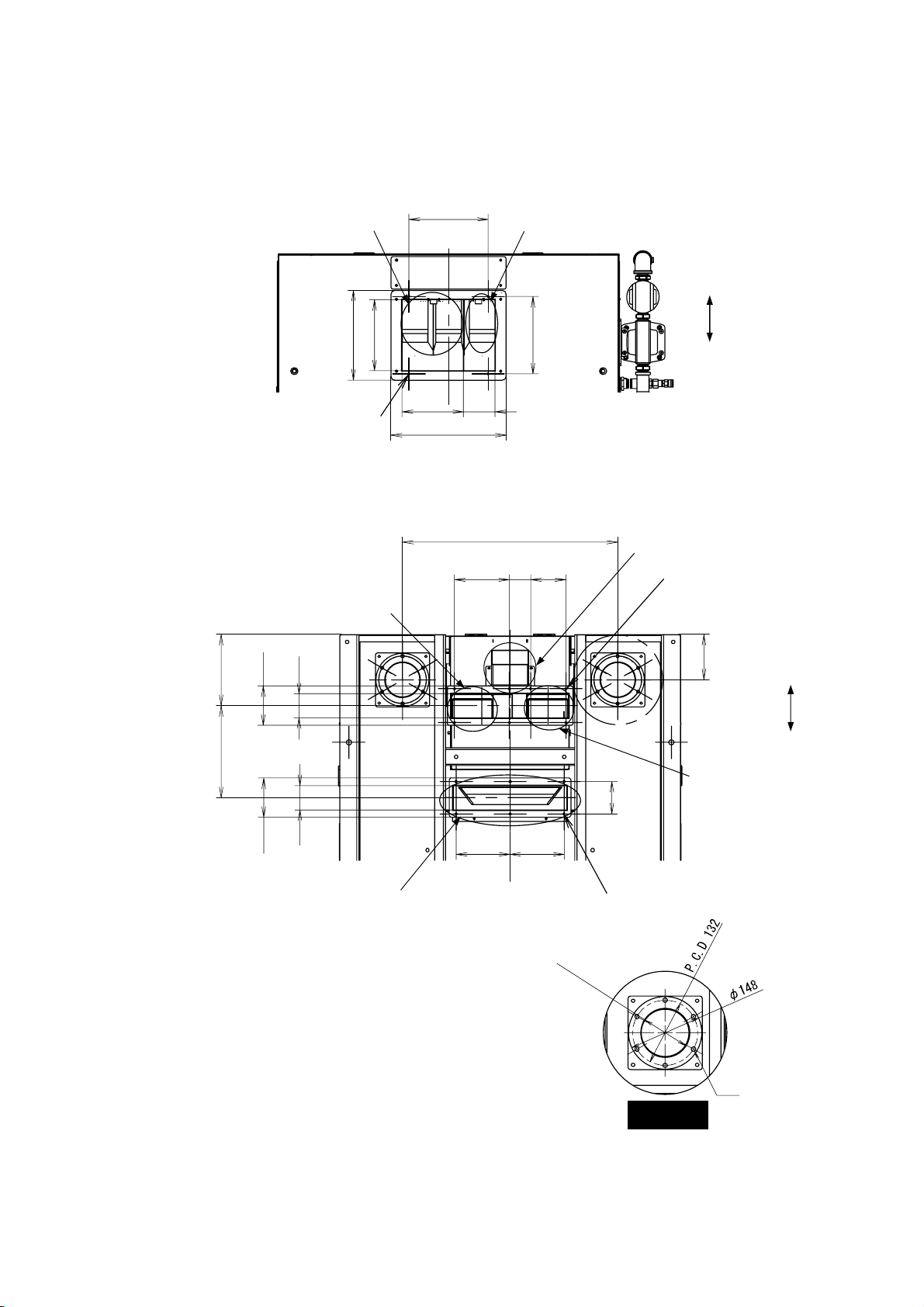
3.2 Dimensions of Inlet, Outlet and Dust-collecting Duct
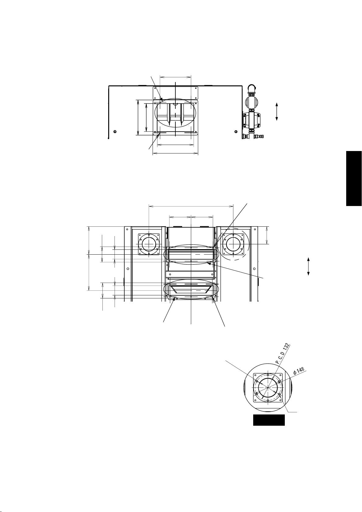
3.2.1 RMGS 284AMS/AIS (Flat 90×2 : U Channel 90×1)
Unit: mm
Primary sorting inlet
220
Secondary sorting inlet
Rear
250
198
216
Front
4-M6
171
88
320
Fig. 3-1 Dimensions of Inlets
153
599
59 98
Secondary reject outlet
8-M6
A
Primary accept outlet
199
110
67
12
Front
Rear
255.5
110
67
150 150
90
Secondary
accept
outlet
Primary reject outlet
φ
9
6
(
I
n
n
6-M6
e
r
d
i
a
.
)
Detail A
Dust-collecting duct
6φ9 hole
Fig. 3-2 Dimensions of Outlets and Dust-Collecting Duct
- 14 -
A
3.2.2 RMGS 284BM/BI (Flat 90×3 : 0)
Inlet
Unit: mm
220
Rear
250
198
Front
4-M6
259
320
INSTALLATION
SSEMBLY AND
Fig. 3-3 Dimensions of Inlets
599
155 155
6-M6
A
199 255.5
110
67 67
126
Front
Accept
outlet
Rear
110
Reject outlet
6-M6
φ
9
6
(
I
n
n
e
r
d
i
a
.
)
Detail A
Dust-collecting duct
6φ9 hole
Fig. 3-4 Dimensions of Outlets and Dust-Collecting Duct
- 15 -
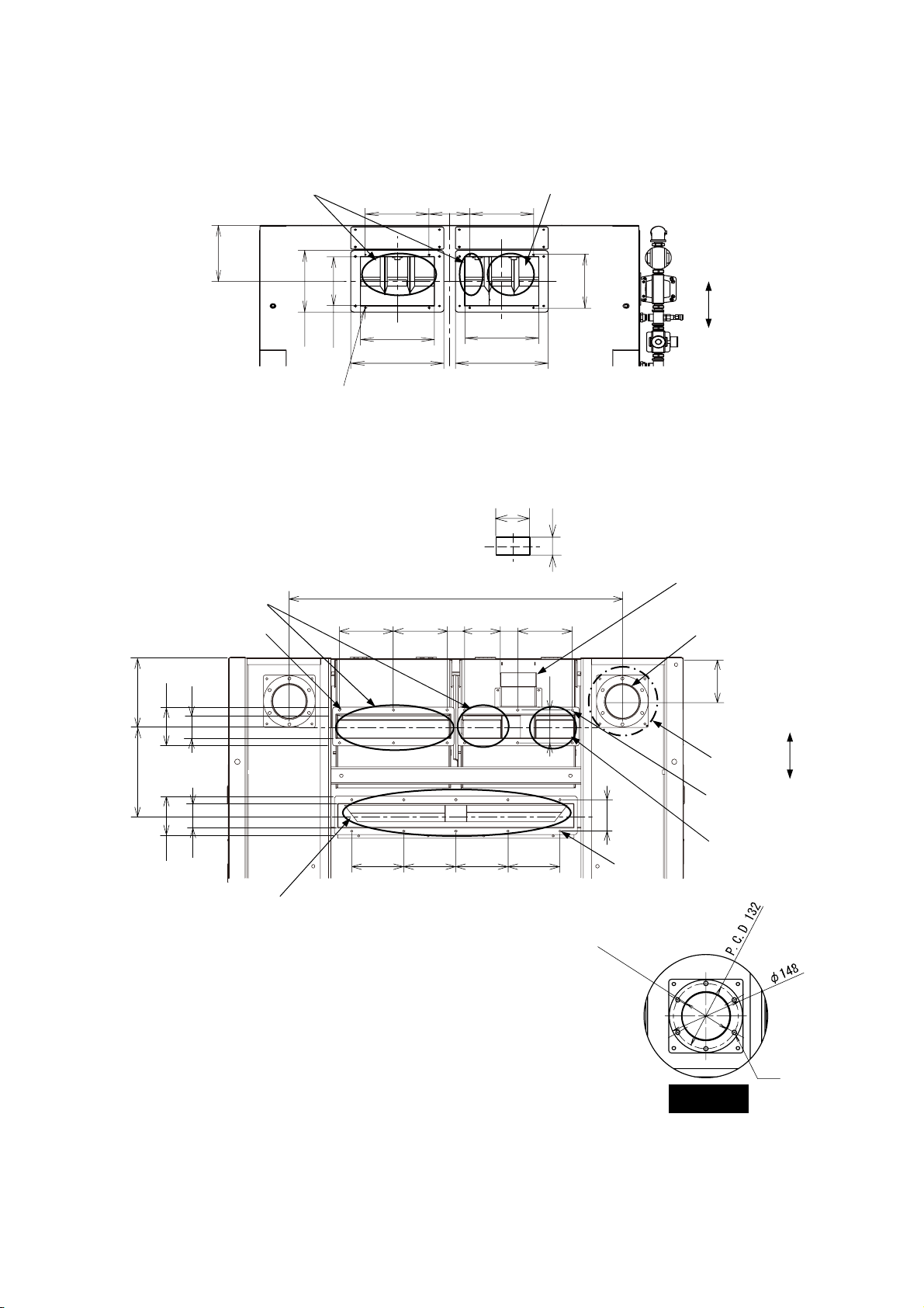
3.2.3 RMGS 564AMS/AIS (Flat 280×1, Flat 90×1 : U Channel 90×2)
Primary sorting inlet
220 140 220
Secondary sorting inlet
Unit: mm
Primary accept outlet
199
110
67
227
6-M6
250
198
4×2-M6
255/259
255/259
320 320
Fig. 3-5 Dimensions of Inlets
103
58
959
155 155 50 98 59 155
94
Rear
216
Front
Secondary
reject outlet
2-5” dust-collecting
duct
126
Front
255.5
A
8-M6
Rear
90
Primary reject outlet
110
67
150 150 150 150
φ
9
6
10-M6
(
I
n
n
e
r
d
i
a
.
)
Secondary
accept outlet
6φ9 hole
Detail A
Fig. 3-6 Dimensions of Outlets and Dust-Collecting Duct
Dust-collecting duct
(Serial No.41730015 and higher)
- 16 -
A
r
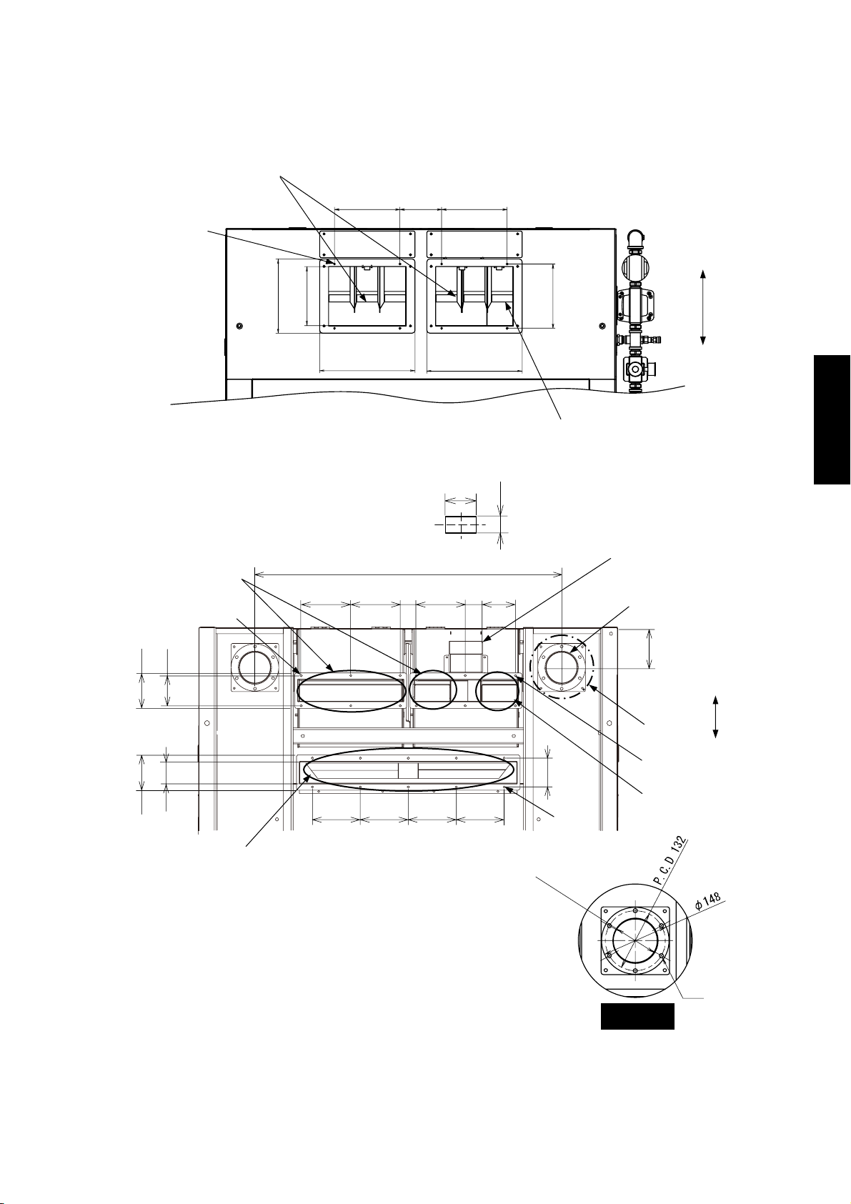
3.2.4 RMGS 564AMS/AIS (Flat 280×1, Flat 90×2 : U Channel 90×1)
Primary sorting inlet
220 140 220
2×4-M6
250
198
320 320
216
Unit: mm
Rea
Front
INSTALLATION
SSEMBLY AND
Primary accept outlet
110
94
67
110
Primary reject outlet
6-M6
Fig. 3-7 Dimensions of Inlets
103
58
959
155 155 50
153 59
150
150 150 150 150
φ
9
Secondary sorting inlet
Secondary
reject outlet
90
10-M6
6
(
I
n
n
e
r
d
i
a
.
)
2-5” dust-collecting
duct
126
Front
A
8-M6
Secondary
accept outlet
Rear
(Serial No.41730015 and higher)
Detail A
Dust-collecting duct
6φ9 hole
Fig. 3-8 Dimensions of Outlets and Dust-Collecting Duct
- 17 -
3.2.5 GS 564BM/BI (Flat 280×2 : 0)
Unit: mm
Inlet
220 140 220
227
Rear
216
250
198
Front
4×2-M6
255/259
255/259
Fig. 3-9 Dimensions of Inlets
Accept outlet
155 155 50 155 155
6×2-M6
959
2-5” dust-collecting
duct
199
110
67
94
126
Front
255.5
90
A
Rear
67
110
150 150 150 150
10-M6
Reject outlet
φ
9
6
(
I
n
n
e
r
d
i
a
.
)
6φ9 hole
Detail A
(Serial No.41730015 and higher)
Fig. 3-10 Dimensions of Outlets and Dust-Collecting Duct
Dust-collecting duct
- 18 -
A
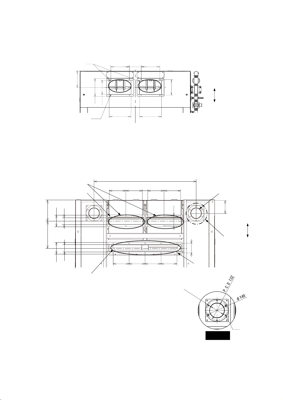
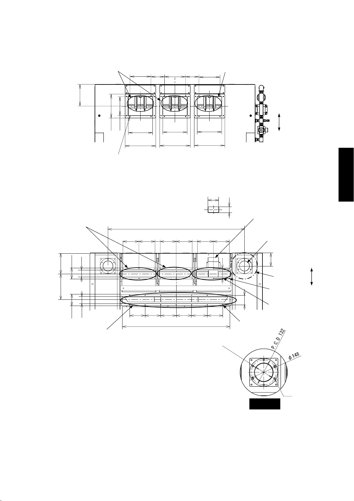
3.2.6 RMGS 844AMS/AIS (Flat 280×2 : U Channel 90×3)
Unit: mm
Primary sorting inlet
227
Primary
accept outlet
67
110
199
250
4×3-M6
220 140 220 140 220
198
259
259 259
320 320 320
Fig. 3-11 Dimensions of Inlets
1319
50
155 155
155 155 50 155 155
103
Secondary sorting inlet
Rear
Front
58
Secondary
reject outlet
2-5” dust-collecting
94
126
A
duct
Front
INSTALLATION
SSEMBLY AND
255.5
67
110
Primary reject outlet
150 150 150 150 150 150
1037
φ
90
14-M6
9
6
(
I
n
n
e
r
d
i
a
.
)
3×6-M6
Secondary
accept outlet
Rear
Detail A
Dust-collecting duct
6φ9 hole
Fig. 3-12 Dimensions of Outlets and Dust-Collecting Duct
- 19 -
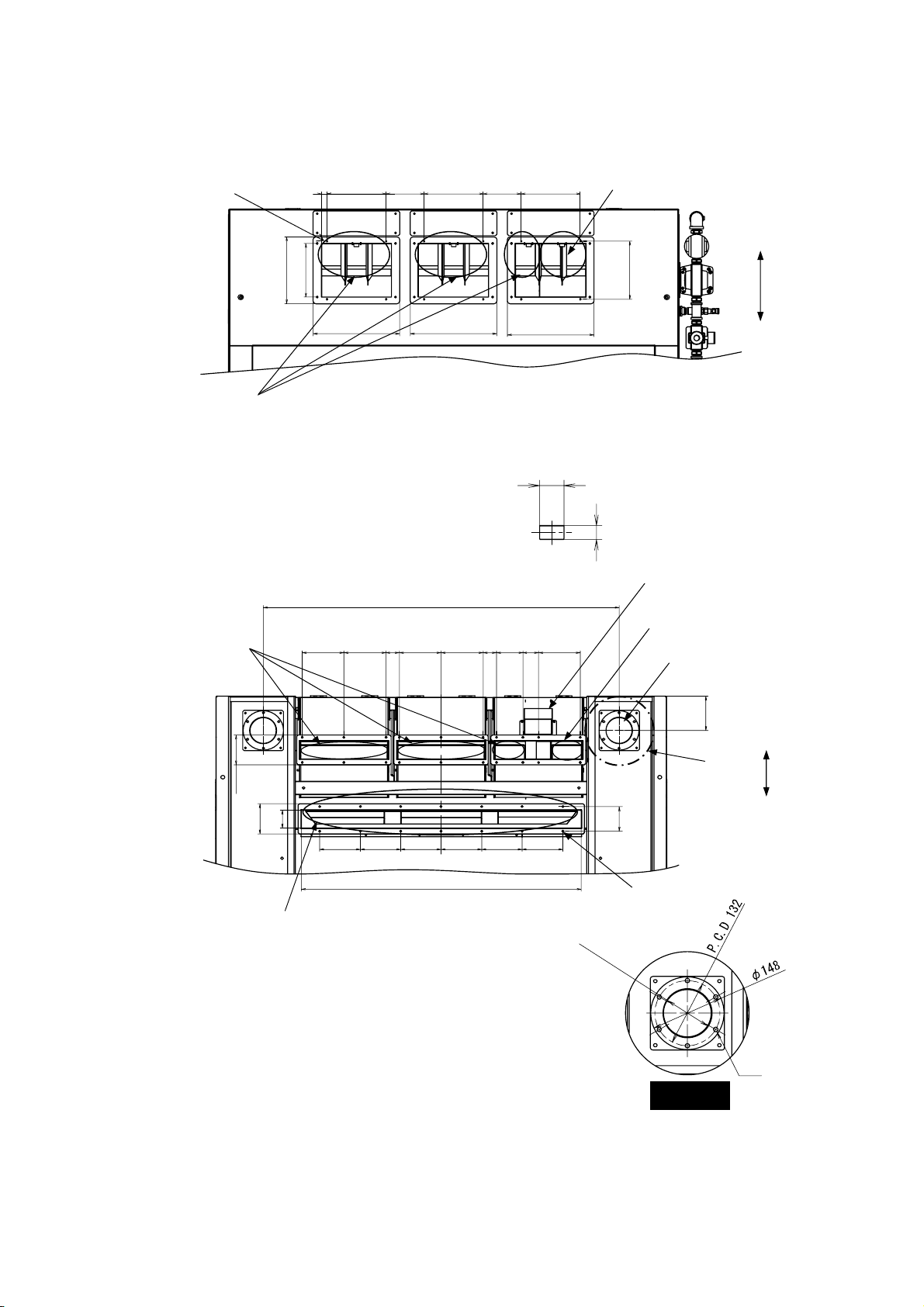
3.2.7 RMGS 844AMS/AIS (Flat 280×2, Flat 90×1 : U Channel 90×2)
Unit: mm
3×4-M6
Prymary sprting inlet
Primary
accept outlet
220 140 220 140 220
250
200
320
Fig. 3-13 Dimensions of Inlets
155 155
320 320
103
1319
50
155 155509859153
Secondary sorting inlet
Rear
216
Front
58
Secondary reject outlet
Secondary accept outlet
2-5” dust-colelcting duct
126
Front
A
110
67
110
150 150 150 150 150 150
90
Rear
Primary reject outlet
1037
φ
9
6
(
I
n
n
14-M6
e
r
d
i
a
.
)
6φ9 hole
Detail A
Dust-collecting duct
Fig. 3-14 Dimensions of Outlets and Dust-Collecting Duct
- 20 -
 Loading...