

Sata RAID 5 User Manual

SATA RAID (RAID 5) Function
(Only for chipset Sil3114 used)
User’s Manual
12ME-SI3114R-002

Table of Contents
1 WELCOME.................................................................................................................................................4
1.1 SATARAID5 FEATURES................................ ...........................................................................................4
1.2 FOR SATARAID USERS UPGRADING TO SATARAID5..............................................................................4
1.2.1 RAID FUNCTION LIST FOR DIFFERENT VERSIONS OF BIOS AND RAID DRIVER...........................................4
1.2.2 UPGRADE BIOS AND RAID DRIVER................................................................ ............................................ 5
2 AN INTRODUCTION TO RAID ...............................................................................................................6
2.1 DISK STRIPING (RAID 0) .............................................................................................................................6
2.2 DISK MIRRORING (RAID 1).........................................................................................................................6
2.3 DISK MIRRORING AND STRIPING (RAID 10)................................ ............................................................... 6
2.4 PARITY RAID (RAID 5)............................................................................................................................... 7
2.5 JBOD (J
UST BUNCH OF DISKS
)....................................................................................................................7
3 INSTALLING DRIVERS ...........................................................................................................................8
4 JAVA 2 RUNTIME ENVIRONMENT INSTALLATION........................................................................9
5 SATARAID5 GUI INSTALLATION.......................................................................................................11
6 CREATING AND DELETING LEGACY RAID GROUPS WITH BIOS UTILITY............................12
6.1 CREATING RAID GROUPS................................ ......................................................................................14
6.2 CREATING SPARE DRIVE.........................................................................................................................15
6.3 CREATING JBOD (SINGLE).....................................................................................................................15
6.4 DELETING RAID GROUPS, SPARE DRIVE, AND JBOD...........................................................................16
6.5 REBUILD RAID 1 SET .............................................................................................................................17
6.6 RESOLVING CONFLICTS..........................................................................................................................18
6.7 LOW LEVEL FORMATTING......................................................................................................................20
6.8 LOGICAL DRIVE INFORMATION .............................................................................................................20
6.9 RESERVED DRIVE AND SETTING SIZE FOR RAID SET, SPARE DRIVE, OR JBOD .................................20
7 ALLOCATING PARTITIONS IN WINDOWS................................ .......................................................22
7.1 W
INDOWS SERVER
2003 & XP & 2000 ..................................................................................................22
7.1.1 CREATING THE PARTITIONS....................................................................................................................23
SATARAID5 User’s Manual
2

8 SATARAID5 GUI OVERVIEW...............................................................................................................27
8.1 RAID GROUPS AND DEVICE CONFIGURATION WINDOWS.....................................................................27
8.2 SATARAID5 MENU COMMANDS ...........................................................................................................29
8.2.1 C
ONFIGURATION
...................................................................................................................................30
8.2.2 EXIT......................................................................................................................................................34
8.2.3 C
REATE SPARE
......................................................................................................................................35
8.2.4 DELETE SPARE ................................ ......................................................................................................35
8.2.5 D
ELETE MEMBER
..................................................................................................................................36
8.2.6 DELETE ORPHAN................................................................ ...................................................................36
8.2.7 DEVICE SUMMARY................................................................ ................................................................ 37
8.2.8 CREATE RAID GROUP...........................................................................................................................38
8.2.9 REBUILD RAID GROUP .........................................................................................................................40
8.2.10 DELETE RAID GROUP.........................................................................................................................40
8.2.11 RAID GROUP SUMMARY .....................................................................................................................41
8.2.12 TASK MANAGER...................................................................................................................................43
8.2.13 EVENT LOG..........................................................................................................................................47
8.2.14 RESOURCES................................................................................................ .......................................... 49
8.2.15 CREATE LEGACY RAID GROUP............................................................................................................49
8.2.16 R
EBUILD LEGACY
RAID G
ROUP
..........................................................................................................50
8.2.17 DELETE LEGACY RAID GROUP............................................................................................................50
8.2.18 C
ONVERT LEGACY
RAID G
ROUP
.........................................................................................................51
8.2.19 CREATE LEGACY SPARE .......................................................................................................................51
8.2.20 D
ELETE LEGACY SPARE
.......................................................................................................................52
8.2.21 CONVERT LEGACY SPARE .................................................................................................................... 52
8.2.22 HELP TOPICS........................................................................................................................................53
8.2.23 A BOUT.................................................................................................................................................53
SATARAID5 User’s Manual
3

1 Welcome
Silicon Image’s SATARAID5TM software provides Serial ATA RAID 0 (Striping), RAID 1 (Mirroring), RAID 5 (Parity RAID),
RAID 10 (Striping and Mirroring), and JBOD (just a bunch of disks) functionality to enhance the industry’s leading PCI-toSATA host controller products. Two major challenges facing the storage industry today are keeping pace with the increasing
performance demands of computer systems by improving disk I/O throughput and providing data accessibility in the face of
hard disk failures while utilizing full disk capacity. With SiIicon Image Serial ATA host controller and SATARAID5, both of
these problems are solved.
SATARAID5 software provides a Graphical User Interface (GUI) for easy-to-use configurations of the RAID Groups.
1.1 SATARAID5 Features
• RAID 0, RAID 1, RAID 5, RAID 10, and JBOD Groups are supported.
• Supported OS: Win2000/XP/Server 2003.
• RAID Groups can be created and deleted without exiting Windows.
• Hot Spare and On-line Rebuilding. The spare policy supports testing periodically for a health check of the spare disk.
Spare drive can be global or dedicated to a specific RAID group.
• Supports Auto and Manual rebuild policy for a RAID group.
• System GUI Monitoring Utility:
• Displays/Logs/Alerts Users to Vital RAID Group Information.
• Manages RAID Group Functions (configures, rebuilds, etc.,).
• Supports the ability to partition and map a segment of disk to a virtual LUN or disk.
• Supports up to two RAID groups. Any excess capacity on disk drives can be formatted as independent logical drives.
• Adjustable Stripe Size for RAID 0, RAID 5, and RAID 10.
• Uses the Self-Monitoring, Analysis, and Reporting Technology (SMART) feature in the attached drives for automatic
notification of imminent drive failures.
• Employ RAID recovery algorithms to maintain data integrity in the event of a disk failure including bad block
management.
• Automatically Selects Highest Available Transfer Speed for All SATA Devices. Supports the following:
• Data transfer rate up to 150MB/Sec (SiI3114, SiI3124-1), and 300MB/Sec (SiI3124-2)
• Support up to 4 SATA devices connected to a single controller.
• ACPI, SATA 1.0 (SiI3114, Sii3124-1), and SATA 2.0 (SiI3124-2)
• Supports drive roaming capability allowing drives from one controller to be moved to another without loss of data.
• Employs a task manager for the scheduling of any RAID or disk management operations including RAID group creation,
rebuild, and test.
1.2 For SATARaid Users upgrading to SATARaid5
If you plan to upgrade to RAID 5 driver and/or BIOS from previous drivers without RAID 5 capability, read this section
carefully before upgrading BIOS and/or RAID driver. Otherwise, you might get unexpected results.
We do not recommend downgrading from RAID 5 driver to the previous (non-RAID 5) RAID driver.
1.2.1 RAID Function List for Different Versions of BIOS and RAID Driver
The following list shows possible BIOS and RAID driver combination and RAID functions supported by each combination.
(Legacy RAID group is a RAID set that is compatible with older SiI3112A, SiI3114, and SiI3124 SATARaid software drivers).
1. Old BIOS with Old RAID Driver
Non-RAID Hard Disk
•
• Legacy RAID 0 group
• Legacy RAID 1 group
• Legacy RAID 10 group
Legacy spare drive
•
2. Old BIOS with New RAID Driver
• Legacy RAID 0 group
SATARAID5 User’s Manual
4

• Legacy RAID 1 group
• Legacy RAID 10 group
• Legacy spare drive
• New RAID 0 group (BIOS will not recognize this)
• New RAID 1 group (BIOS will not recognize this)
• New RAID 5 group (BIOS will not recognize this)
• New RAID 10 group (BIOS will not recognize this)
• New spare drive (BIOS will not recognize this)
• JBOD (BIOS will not recognize this)
3. RAID 5 BIOS with Old RAID Driver
Legacy RAID 0 group
•
• Legacy RAID 1 group
• Legacy RAID 10 group
• Legacy spare drive
4. RAID 5 BIOS with New RAID Driver
• Legacy RAID 0 group
• Legacy RAID 1 group
• Legacy RAID 10 group
Legacy spare drive
•
• New RAID 0 group
• New RAID 1 group
• New RAID 5 group
New RAID 10 group
•
• New spare drive
• JBOD
1.2.2 Upgrade BIOS and RAID Driver
If you upgrade from old BIOS and old RAID driver to a newer version of BIOS and/or RAID drive, you may lose some
functions. Also, the new driver may not recognize non-RAID drives. If you are upgrading the software driver from the
previous non-RAID 5 versions, the following is a list of precautions users should realize before upgrading BIOS and RAID
driver to a newer version.
1. If you’re upgrading to RAID 5 driver only:
• If the boot drive is a non-RAID drive, the system will not boot.
• No non-RAID drive support.
• When creating RAID groups through GUI, only those RAID groups created in legacy mode will be recognized by
BIOS.
• The existing RAID 0 or RAID 10 groups (created with previous version of BIOS or GUI) with 4 KB stripe size will not
work.
2. If you’re upgrading to RAID 5 BIOS only:
• If the boot drive is a non-RAID drive, the system will not boot.
• No non-RAID drive support.
• RAID driver will not recognize JBOD and RAID 5 group created by BIOS.
3. If you’re upgrading to RAID 5 BIOS and RAID 5 driver
• If the boot drive is a non-RAID drive, the system will not boot.
No non-RAID drive support.
•
• The existing RAID 0 or RAID 10 groups (created with previous version of BIOS or GUI) with 4 KB strip size will not
work.
SATARAID5 User’s Manual
5
Block 0
Block 1
Block 2
Block 3
Block 0
Block 1
Block 2
Block 3
2 An Introduction to RAID
RAID - Redundant Array of Independent Disks
RAID technology manages multiple disk drives to enhance I/O performance and provide redundancy in order to withstand
the failure of any individual member, without the loss of data. There are many different methods of implementation for RAID,
with each having advantages and disadvantages. Raid levels or set types are given a numerical designator that defines its
implementation such as RAID 0 or RAID 1. SATARAID5 provides support for three RAID Group types: Striped (RAID 0),
Mirrored (RAID 1), and RAID 10 Mirrored/Striped. Other RAID types are not supported by SATARAID5 software and thus are
not discussed.
2.1 Disk Striping (RAID 0)
Striping is a performance-oriented, non-redundant data mapping technique. While Striping is discussed as a RAID Group
type, it is does not provide any fault tolerance. With modern SATA and ATA bus mastering technology, multiple I/O
operations can be performed in parallel, enhancing data throughput. Striping arrays use multiple disks to form a larger
virtual disk. The figure below illustrates a three-disk stripe set. Stripe one is written to disk one, stripe two to disk two, and so
forth. RAID 0 sets can be comprised of two, three, or four drives.
Stripe0
Stripe3
Stripe6
Stripe9
Stripe1
Stripe4
Stripe7
Stripe10
Stripe2
Stripe5
Stripe8
Stripe11
2.2 Disk Mirroring (RAID 1)
Disk mirroring creates an identical twin for a selected disk by having the data simultaneously written to two disks. This
redundancy provides instantaneous protection from a single disk failure. If a read failure occurs on one drive, the system
reads the data from the other drive. RAID 1 sets are comprised of two drives. A third drive can be allocated as a spare in
case one of the drives in the set fails.
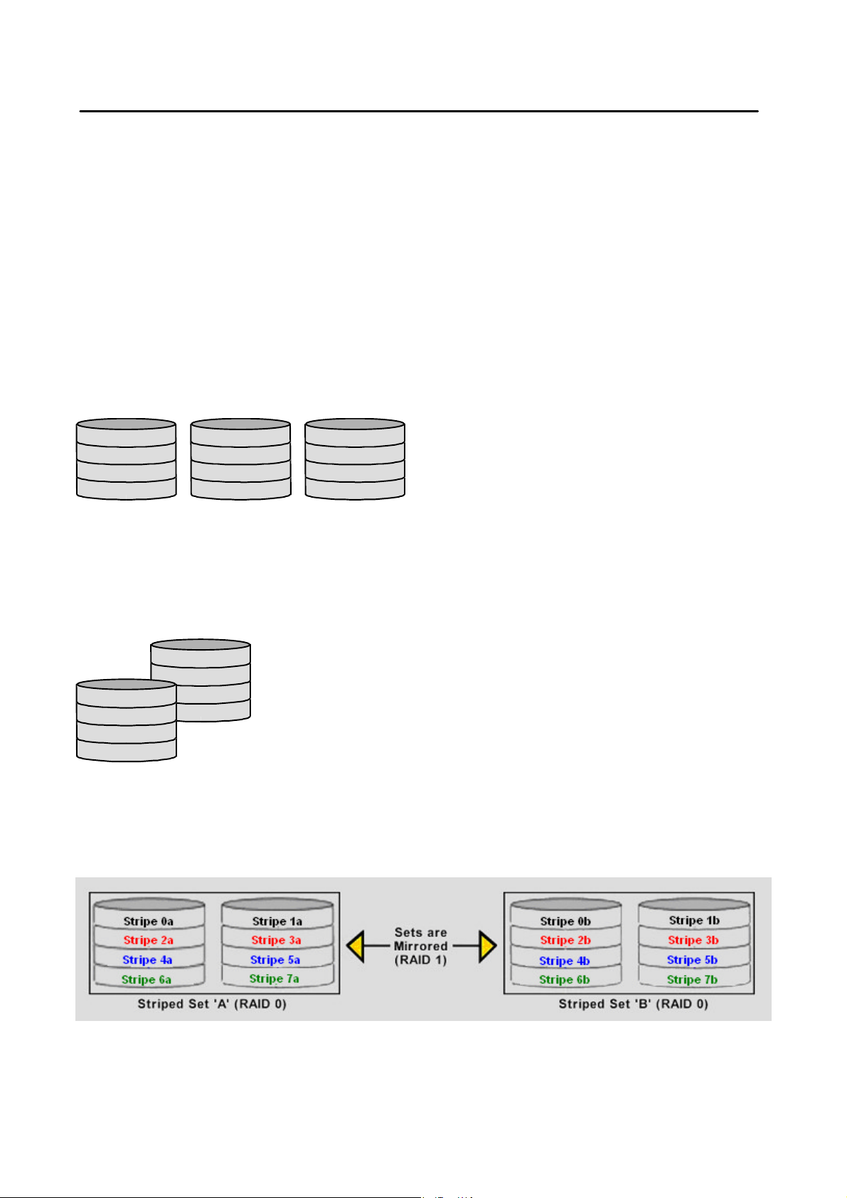
2.3 Disk Mirroring and Striping (RAID 10)
RAID 10 combines the features of both RAID 0 and RAID 1. Performance is provided through the use of Striping (RAID 0),
while adding the fault tolerance of Mirroring (RAID 1). The implementation of RAID 10 requires four drives. The drives are
assigned as two sets of striped pairs.
SATARAID5 User’s Manual
6
The data is written to RAID Group A, which is striped (RAID 0). This allows maximum speed. The data is then mirrored to
another RAID 0 striped set, which is Set B in the figure above. This provides data redundancy (RAID 1), and thus increased
data security.
Under certain circumstances, a RAID 10 set can sustain multiple simultaneous drive failures.
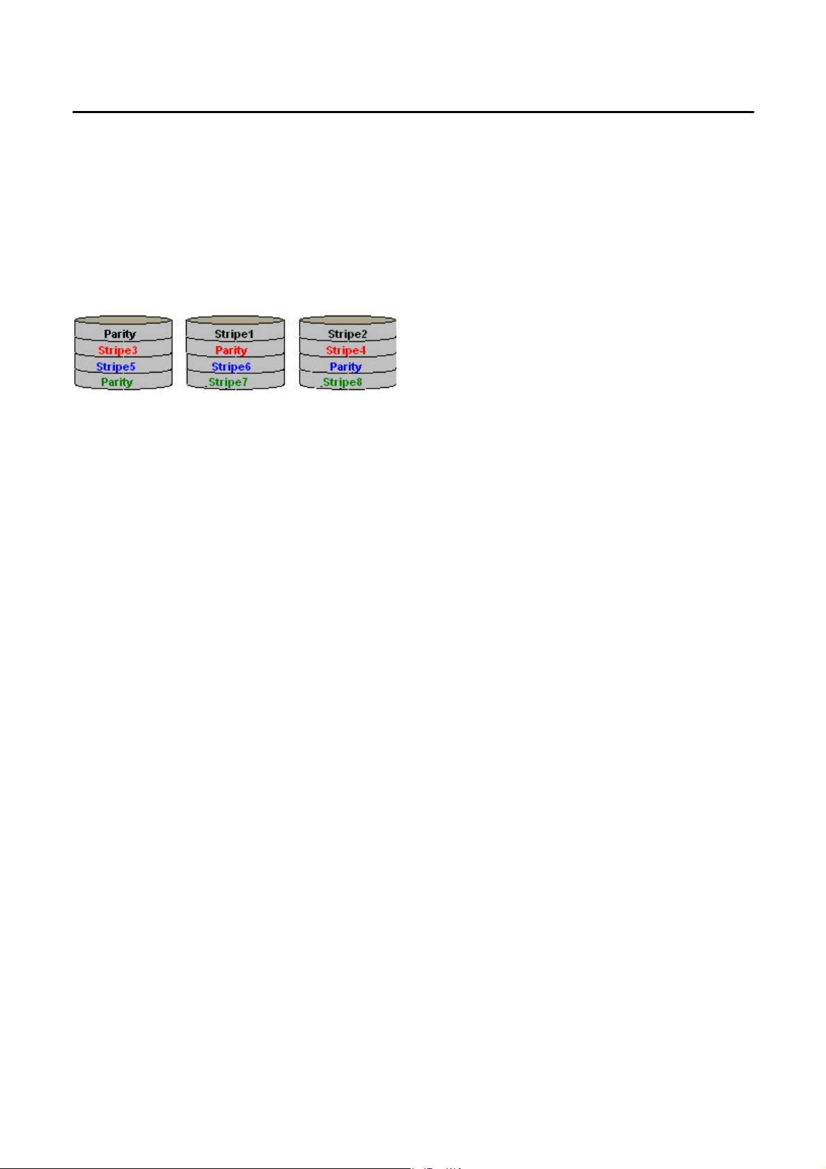
2.4 Parity RAID (RAID 5)
Parity or RAID 5 adds fault tolerance to Disk Striping by including parity information with the data. Parity RAID dedicates the
equivalent of one disk for storing parity stripes. The data and parity information is arranged on the disk array so that parity is
written to different disks. There are at least 3 members to a Parity RAID set. The following example illustrates how the parity
is rotated from disk to disk.
Parity RAID uses less capacity for protection and is the preferred method to reduce the cost per megabyte for larger
installations. Mirroring requires 100% increase in capacity to protect the data whereas the above example only requires a
50% increase. The required capacity decreases as the number of disks in the group increases.
2.5 JBOD (Just Bunch of Disks)
The JBOD is a virtual disk that can either be an entire disk drive or a segment of a single disk drive. For home edition,
JBOD function only supports one disk.
SATARAID5 User’s Manual
7
g
g
3 Installing Drivers
Before installing Windows 2000/XP onto a serial ATA hard disk on the Silicon Image Serial ATA controller, the Silicon Image
Serial ATA controller driver must be installed. The following steps explain how to copy the Serial ATA controller driver from
the motherboard driver CD-ROM to a floppy disk in MS-DOS mode and install the driver during OS installation. Please
prepare a startup disk that has CD-ROM support and a blank formatted disk.
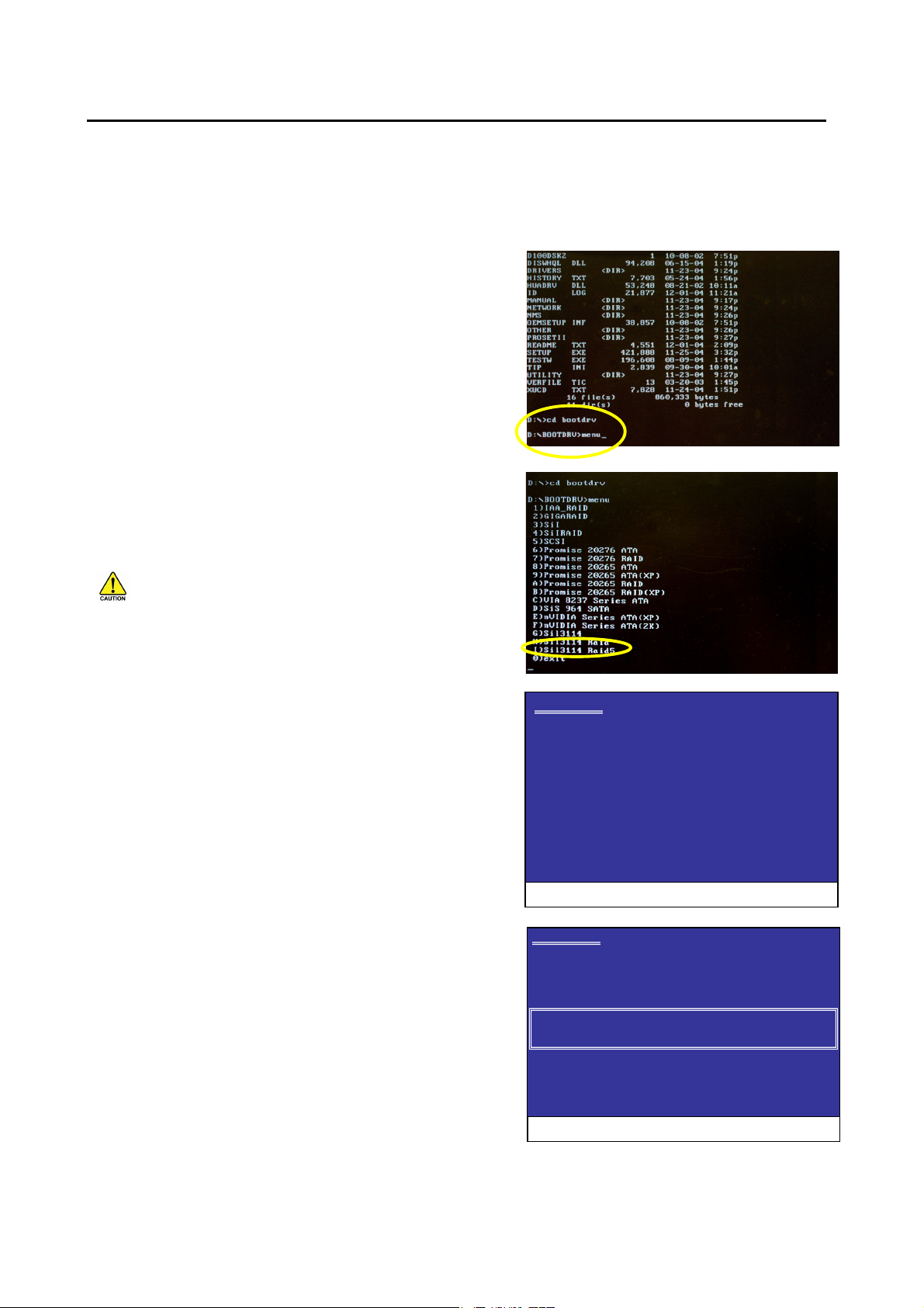
Step 1: Insert the prepared startup disk and motherboard driver CDROM in your system. Boot from the startup disk. Once at the A:\>
prompt, change to the CD-ROM drive (example: D:\>). At the D:\>
prompt, type the following two commands. Press ENTER after each
command (Figure 1):
cd bootdrv
menu
Note: For users without a startup disk.
Use an alternative system and insert the GIGABYTE motherboard driver
CD-ROM. From the CD-ROM drive (example: D:) double click the
MENU.exe file in the BootDrv folder. A command prompt window will
open similar to that in Figure 2.
Step 2: When the controller menu (Figure 2) appears, remove the
startup disk and insert the blank formatted disk. Select the Sil3114
Raid5 driver by pressing the corresponding letter from the menu. Your
system will then automatically zip and transfer this driver file to the
floppy disk. Press 0 to exit when finished.
Figure 1
You MUST select the Sil3114 Raid5 item no matter what
RAID mode (RAID 0, RAID 1, RAID 5, RAID 10, JBOD, etc.) you
want to create. If you wish to set up a non-RAID confi
uration, you
must select Sil3114 Raid5, too. Do not select Sil3114 or Sil3114
Raid, or you will fail to install the operating system.
Figure 2
Step 3: To install an operating system, boot from the Windows
Windows Setup
installation disk. Press F6 as soon as you see the "Press F6 if you need
to install a third party SCSI or RAID driver" message (Figure 3). In the
next screen, press S to specify additional device(s) as instructed and
supply the serial ATA controller driver on the floppy disk.
Step 4: When a controller menu appears (Fi
ure 4), select a controller
based on the operating system you wish to install and press ENTER.
Press ENTER again in the next screen to begin installing the driver.
When the driver installation is finished, proceed with the installation of
the Windows operating system.
Press F6 if you need to install a third party SCSI or RAID driver
Figure 3
Windows Setup
You have chosen to configure a SCSI Adapter for use with Windows,
using a device support disk provided by an adapter manufacturer.
Select the SCSI Adapter you want from the following list, or press ESC
to return to the previous screen.
Silicon Image Sil 3114 SoftRAID 5 Controller for Windows XP/Server 2003
Silicon Image Sil 3114 SoftRAID 5 Controller for Windows 2000
ENTER= Select F3=Exit
SATARAID5 User’s Manual
Figure 4
8
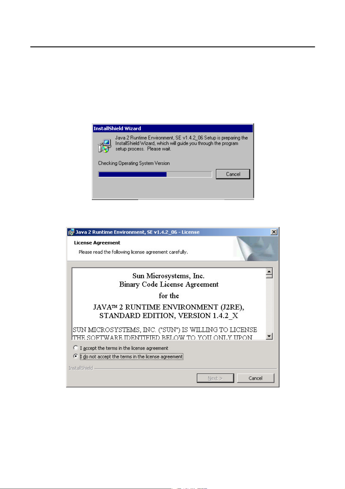
4 JAVA 2 Runtime Environment Installation
The Java 2 Runtime Environment is required for the SATARAID5 GUI. The Java 2 Runtime Installer and executable package
must be downloaded from the Sun Microsystems website at http://java.sun.com/j2se/downloads.html. The computer must
have an Internet connection set up before installation can proceed.
Save the installer file to a known location, such as the My Documents folder. Using Windows Explorer or by clicking on the
My Computer icon on the desktop, select the installation file and open it. The installation will begin. The installer program will
download the needed files from the Internet. (You may also find the J2RE file from motherboard driver CD. The file is
located in the Other\SiI\R5Tool folder in the driver CD.)
When a window appears asking for acceptance the license agreement, select
and click Next.
I accept the terms of this license agreement
SATARAID5 User’s Manual
9
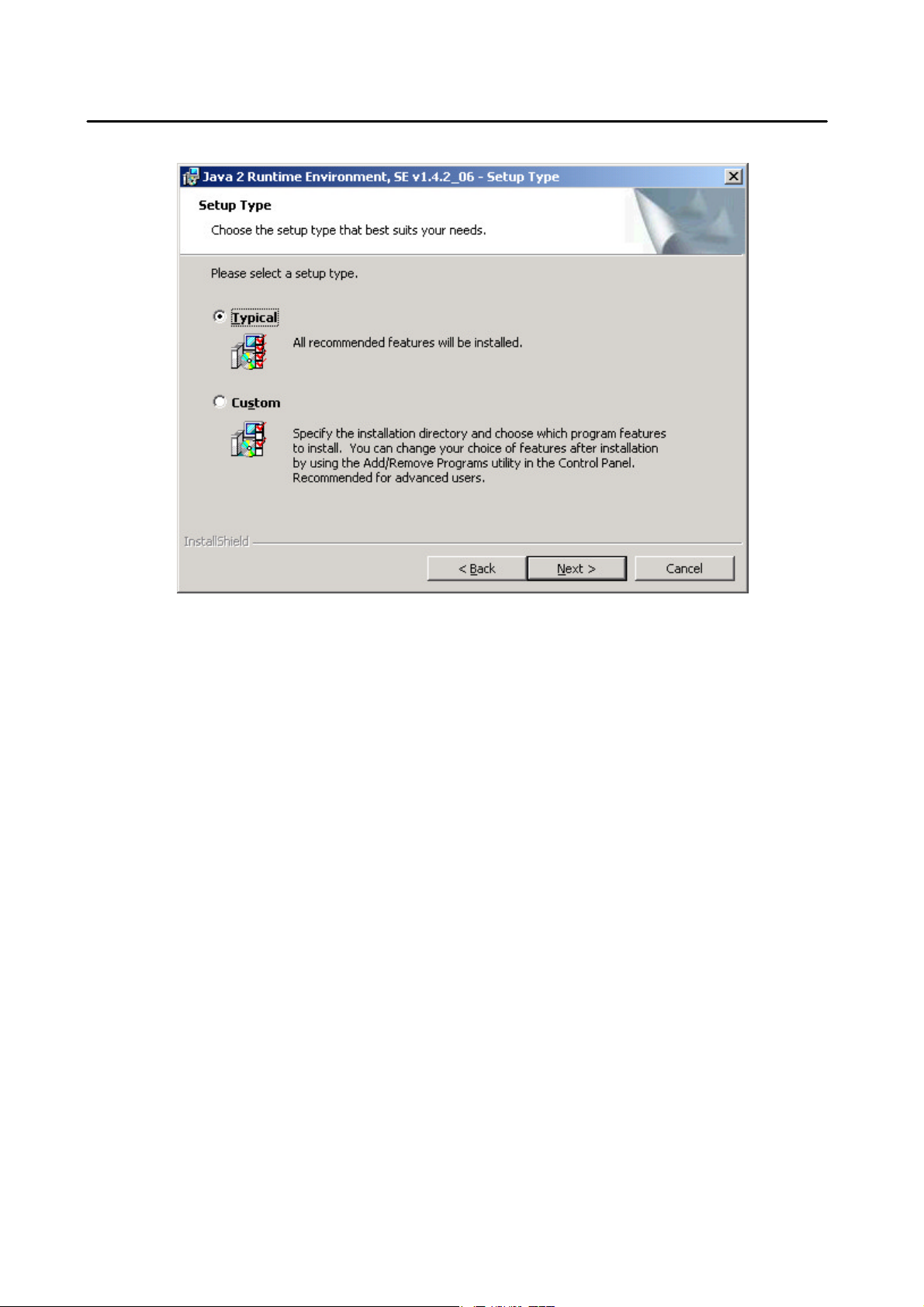
Choose the Typical setup type and click Next.
When the installation completes, click Finish. Restart the computer when prompted.
SATARAID5 User’s Manual
10
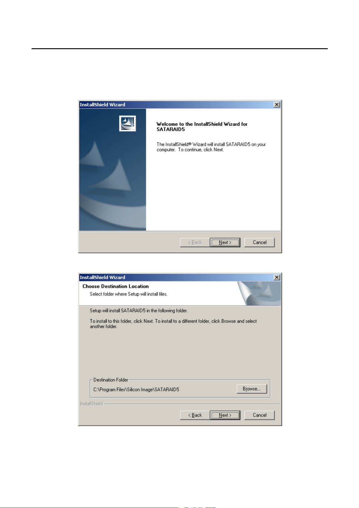
5 SATARAID5 GUI Installation
Insert the motherboard driver CD into the computer’s CD -ROM drive. When the autorun window appears, click the
SOFTWARE APPLICATIONS button at the left of the window. Move the scroll bar to the bottom and you should see Silicon
Image SATA RAID5 Utility. Click this item and the installation will begin.
Click the Next button when the Welcome window appears.
Click the Next button to install the SATARAID5 program in the default directory (recommended). An alternate directory may
be selected if desired.
After installation is done, click the Finish button to complete the installation.
SATARAID5 User’s Manual
11
6 Creating and Deleting Legacy RAID Groups with BIOS
Utility
Legacy RAID sets and JBOD can be created and managed by either the BIOS utility or the SATARAID5 GUI. New RAID
groups must be created and managed by the SATARAID5 GUI. See section 8 SATARAID5 GUI Overview for information on
configuring RAID Groups using the SATARAID5 GUI.
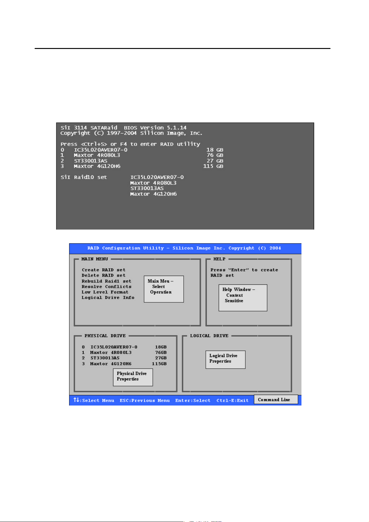
During boot up, a screen similar to that below will appear for about 5 seconds. Press CTRL+S or the F4 key to enter the
BIOS RAID utility.
The RAID Utility menu screen will be displayed. A brief description of each section is presented on the next page.
SATARAID5 User’s Manual
12

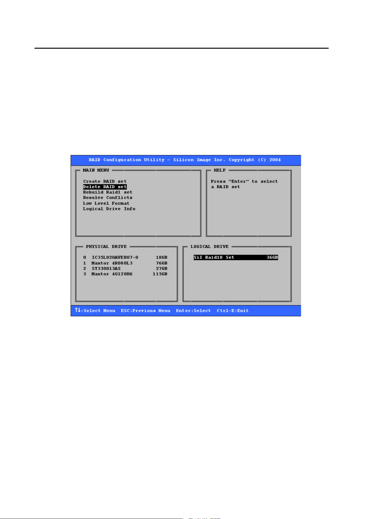
Main Menu
The Main Menu in the upper left corner is used to choose the operation to be performed. The selections are:
Create RAID Group
Delete RAID Group
Rebuild RAID 1 Set
Resolve Conflicts
Low Level Format
Logical Drive Info
Create RAID Group
Delete RAID Group
Rebuild RAID 1 Set
Resolve Conflicts
swapped around, for example) and restore the Set to proper operation.
Low Level Format
spares cannot be low level formatted.
Logical Drive Info
attached to the SATA host adapter.
These operations are detailed in the pages that follow.
is used to create a new legacy RAID Set or for allocating legacy spare drives.
is used to delete a legacy RAID Set or to deallocate a legacy spare drive.
is used to initiate the rebuild of a RAID 1 set after, for example, a drive in the Group has been replaced.
is used to automatically find the member drives of a RAID set which has been disrupted (physical drives
allows a single drive to have its data completely wiped out. Drives assigned to Sets or allocated as
shows the current configuration of each RAID set, allocated spare, and unallocated physical drive
Help Window
This window displays context-sensitive help and status messages.
Physical Drive Information
This window displays the model number and capacities of the drives physically attached to the SATA host adapter.
Logical Drive Information
This window displays all logical drives connected to the controller. The upper part lists RAID sets and JBOD drives reported
to the system BIOS. The lower part lists spare drives, reserved drives, conflict drives, and invalid drives not reported to the
system BIOS.
Command Line
The bottom line of the display lists the currently active command keys:
Up and Down arrows select the menu item or action
ESC takes the user to the previous menu
Enter selects the highlighted choice
Ctrl-E exits the utility
Other keys may be active depending upon the currently selected action.
SATARAID5 User’s Manual
13
6.1 Creating RAID Groups
As previously discussed, the Silicon Image SATA host adapter supports RAID 0, 1, 5, 10, and JBOD configurations. The
selection of the RAID level to be used should be based upon factors including performance, data security, and number of
drives available. It is best to carefully consider the long-term role of the system and plan the data storage strategy
appropriately.
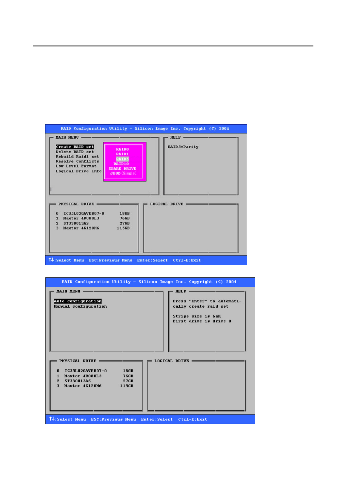
Silicon Image has made the creation of RAID sets very simple. They can be created either automatically or to allow the
greatest flexibility, manually.
1. Select “Create RAID set”
2. Choose a RAID 0 Striped, a RAID 1 Mirrored, a RAID 5 Parity, or a RAID 10 combination set.
3. Select Automatically or Manually configuration of the RAID Set. Single
SATARAID5 User’s Manual
14
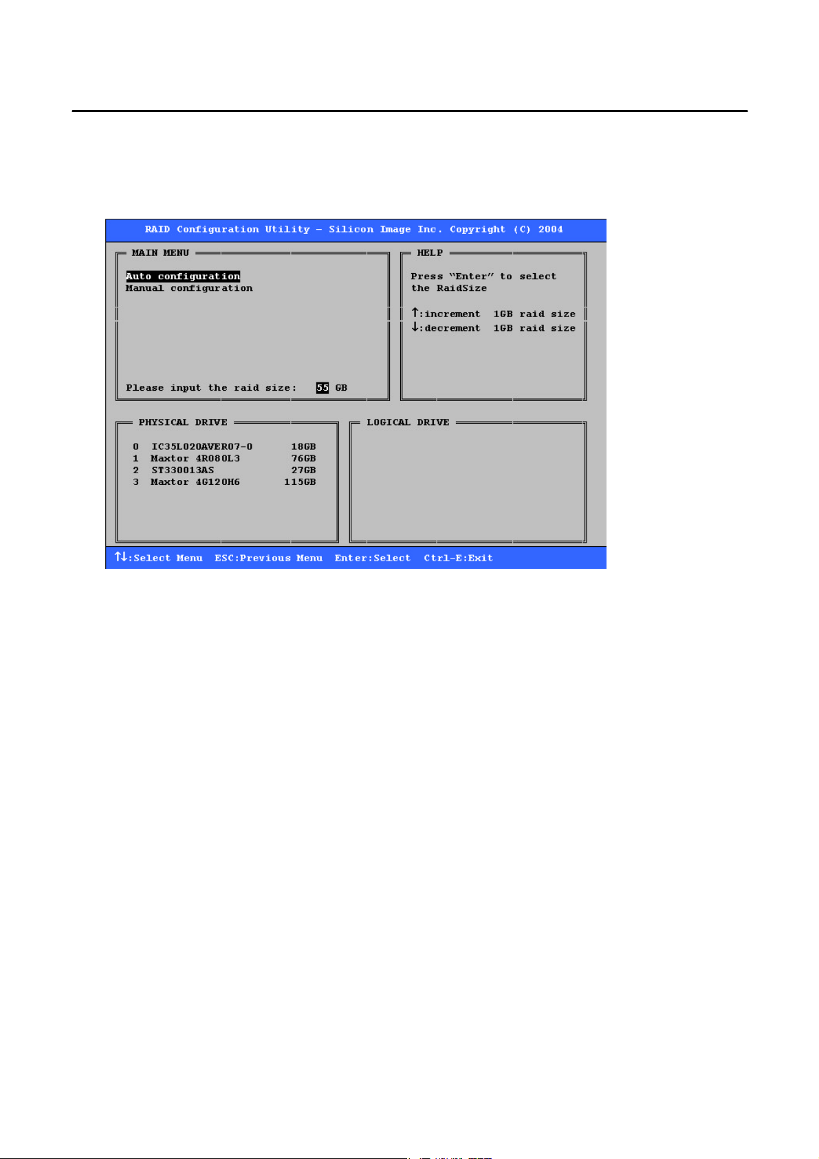
4. If manual configuration is selected, the chunk size of Striped Sets can be selected. For Mirrored Sets, the Source and
Target drives can be selected.
5. If auto configuration is selected, BIOS will select RAID member drives automatically and the chunk size of Striped Sets
is set to 64KB.
6. Select RAID set size with ↑ and ↓ keys. See section 6.9 for explanation on selecting size.
7. After the RAID set size is set, the message “Are You Sure?” will display before completing the configuration. Answer
“N” to abort the creation of the new RAID set, or “Y” to proceed with the RAID set creation.
8. RAID sets can be created in both BIOS and in the SATARaid5 GUI. If you have excess capacity left on your hard
drives after creating a RAID set in the BIOS, you can later go to the SATARaid5 GUI to create additional logical drives
that fully utilize the capacity on all your hard drives.
6.2 Creating Spare Drive
If there is a RAID 1/RAID 5/RAID 10 set, spare drive can be created. The spare drive can be allocated to the RAID 1/RAID
5/RAID 10 set in the event of a failure of one of the drives in the RAID 1/RAID 5/RAID 10 set.
1. To create a spare drive for RAID 1 set, Select “Create RAID set”
2. Select “Spare Drive” and press Enter.
3. Select spare drive from the physical drive list and press Enter.
4. Select spare drive size with ↑ and ↓ keys. See section 6.9 for explanation on selecting size.
5. After the spare drive size is set, the message “Are You Sure?” will display before completing the configuration. Answer
“N” to abort the creation of the spare drive, or “Y” to proceed with the spare drive creation.
6.3 Creating JBOD (Single)
Since BIOS no longer reports non-RAID drives to the system BIOS, if a non-RAID boot drive or data drive is desired, a
JBOD can be created so BIOS will report it to the system BIOS.
1. To create a JBOD, Select ”Create RAID set”
2. Select “JBOD” and press Enter.
SATARAID5 User’s Manual
15
3. Select JBOD drive from the physical drive list and press Enter.
4. Select JBOD size with ↑ and ↓ keys. See section 6.9 for explanation on selecting size.
5. After the JBOD size is set, the message “Are You Sure?” will display before completing the configuration. Answer “N”
to abort the creation of the JBOD, or “Y” to proceed with the JBOD creation.
6.4 Deleting RAID Groups, Spare Drive, and JBOD
1. To remove one or more RAID sets, spare drives, and JBODs, select “Delete RAID set”
2. Select the desired item to delete from the logical drive list and press Enter.
3. Press “Y” when asked, “Are You Sure?”
4. The drives will be returned to the selection of logical drives from which a new RAID set can be created.
SATARAID5 User’s Manual
16

6.5 Rebuild RAID 1 Set
This menu selection is used to initiate the copying of data from an existing drive to a replacement drive that has been
installed in a RAID 1 set after the failure of one of the members.
1. Select “Rebuild RAID 1 set”
2. Select the desired set and press Enter.
3. Press “Y” when asked, “Are You Sure?”
4. The set will be rebuilt. The status of the rebuild is displayed in the MAIN MENU window.
SATARAID5 User’s Manual
17
 Loading...