

ASSEMBLY AND CARE INSTRUCTIONS
PERFORMANCE SERIES SINGLE BAR TRAINER
VERSION: 8920019 (Revised 06/15)
228
SA Sport – Canada and International
135 Forestview Road, PO Box 40
Orillia, Ontario, Canada L3V 6H9
Toll-Free: (800) 563-6479
Telephone: (705) 325-2274
Fax: (705) 325-1485
info@spiethanderson.com
SALES AND SERVICE
sasportonline.com
SA Sport – USA
104 Nu Energy Drive, Suite 1
Aledo, Texas, USA 76008
Toll-Free: (800) 331-8068
Telephone: (817) 536-3366
Fax: (817) 536-3006
sales@sasportusa.com

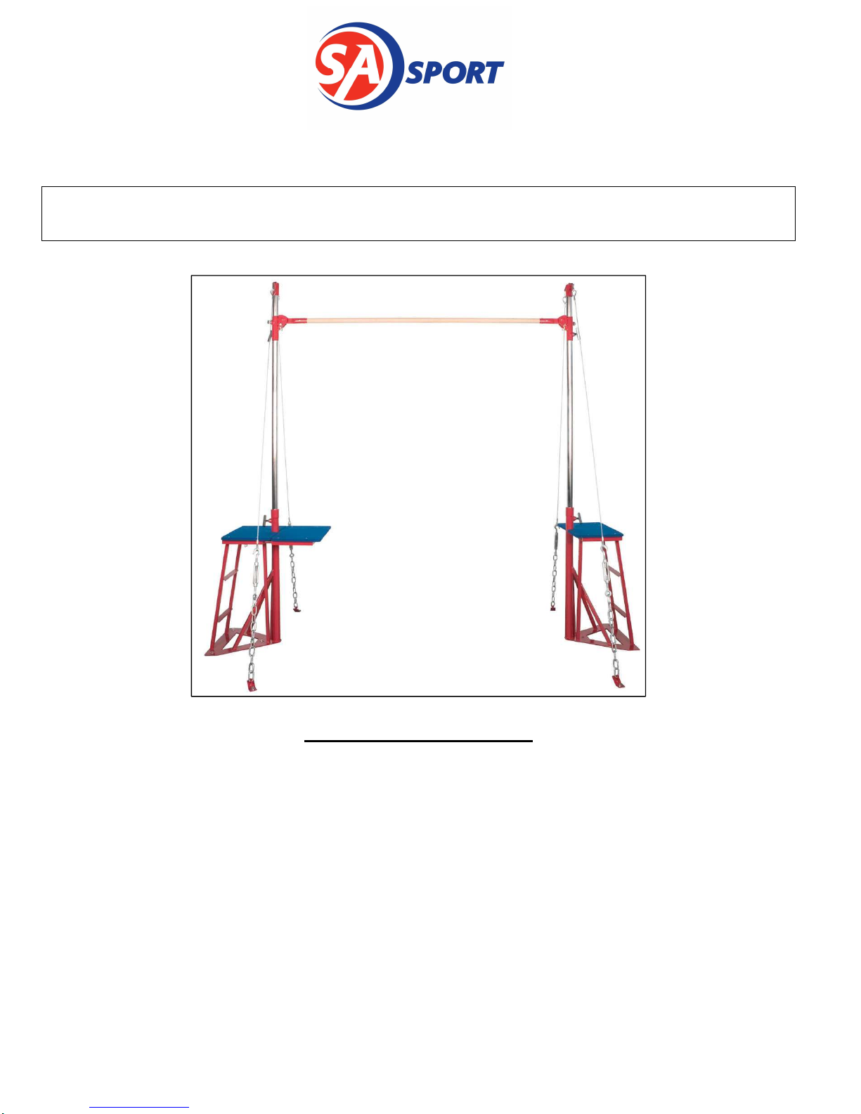
228 PERFORMANCE SERIES SINGLE BAR TRAINER Assembly Instructions
The Performance Series Single Bar Trainer requires 70% less anchor space than a conventional
single bar and has platforms on the inside and outside of the uprights. The inside platform can be
removed quickly and easily when needed.
Our Steel (#P136-10A) and Fiberglass (#P121-99A) rails are completely interchangeable.
• The single bar trainer is designed to save space compared to a conventional cable tiedown system.
• The Apparatus comes complete with a removable Spotting Platform.
• Height adjusts from 50
⅛" (
130cm) to 98
⅜" (250cm) in 8" (20cm) increments and from 98⅜"
(250cm) to 110¼" (280cm) in 2" (5cm) increments.
• Rails are NOT INCLUDED but are Required for Set Up
Please carefully read the following instructions before assembling and using your new equipment, as
they pertain to the particular equipment you have purchased.
The exclamation mark symbol when seen in this manual is used to indicate warnings or items
that require special attention during the use or assembly of the apparatus.
Assembly, set-up and adjustment of this equipment should only be undertaken by
qualified persons. At no time should children or other unqualified persons undertake
the assembly, set-up, installation or adjustment of this equipment.
For assembly, set-up and adjustment instructions, please read and follow all instructions of this
manual as they apply to your particular piece or pieces of equipment.
Be sure to read and follow all Safety Instructions in the last Section of this manual before attempting
to use the apparatus!
Tools Required:
• Tape measure
• Hammer
• 5/8” diameter carbide concrete drill bit
• Anchor setting tool or Drift punch with a 5/16” diameter & at least 1.5” long end
• Hammer drill
• ¾” or 19mm Socket and Ratchet
• 2 adjustable wrenches
• 6ft to 8ft Step Ladder
Single Bar Trainer Packages:
You will have received the following:
• Two Upright bases, including one with a removable Spotting platform
• One box containing the upright adjusting tubes
• One box with the bar carrier assemblies
• One box with cables and tie-downs
Page 2 of 9

228 PERFORMANCE SERIES SINGLE BAR TRAINER Assembly Instructions
1. Assembly Instructions
1.1. Single Bar Trainer pre-assembly
1. Place the Upright Bases in the approximate location where they will be used.
2. Pre-assemble the upright adjusting tubes. Use pictures below for reference.
Do not climb or stand on the bases until they are anchored to the floor.
• Slide the bar carrier onto the bottom of the adjusting tube (See figure below).
• Lock the carrier in place by engaging the Gravity Snaplock Pin into an adjusting tube hole.
• Using quick links, attach cables to the large loops on the top cap. The quick links should be
oriented so they will be tightened by turning the nut down (see picture below). That will
help prevent it from unthreading during the use of the apparatus.
Quick Link
Top Cap
Large Loop
Note that top of
adjusting tube has
2" increments
adjustment holes.
Cable
Adjusting Tube
Upright Base
Gravity
Snaplock
Rail Carrier
Base
Tube
Hold Down
Bracket
Page 3 of 9
 Loading...