

SaskTel maxTV Install Manual

M
Maaxx
IInnssttaallll G
Guuiiddee
SSDD aanndd HHDD EEddiittiioonn
CONNECTIONS CHECKLIST
1. Know your jacks and plugs – most are color coded:
• Yellow plugs are Video connections
• Red plugs are Right Audio connections
• White (or black) plugs are Left Audio (or Mono)
connections. If you VCR is mono-sound, it will
have only a white or black plug, no second red
one.
2. Perform one connection at a time. If you have
several accessories to connect, make sure each
connection is correct by checking to see that it works
properly before trying the next connection.
3. Unplug the power cord during each connection.
4. Follow the In and Out Concept. Remember In and
Out – the Output jack from one devise will go to the
Input jack of the other. Read the jack panels, they
are all labeled
.
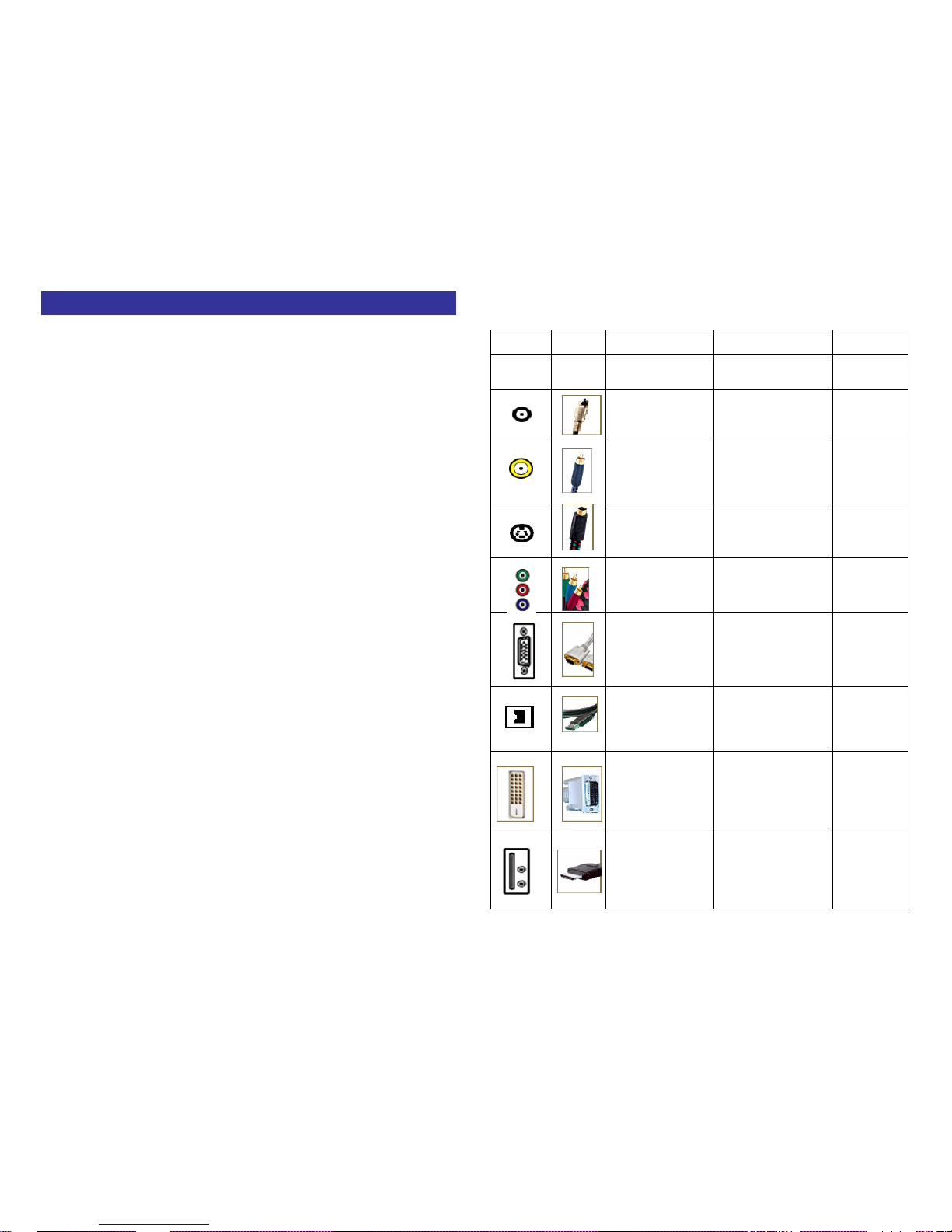
Cables
Video
Jack Cable
Name
Typical Use
Level of
Video
Quality
RF
a.k.a. radio
frequency;
antenna; cable
Antennae, VCRs,
cable and satellite
boxes
Lowest
Composite Video
a.k.a. yellow video;
video; A/V (when
combined with
audio jacks)
Cable and satellite
boxes, VCRs, DVD
players, game
consoles
Low
S-Video
a.k.a. DIN 4
Cable and satellite
boxes, S-VHS VCRs,
DVD players, game
consoles
Medium
Component
a.k.a.
Y, Pb, Pr;
1080i; 720p; HDTV
Regular and
progressive-scan
DVD players, HDTV
receivers
Very High
RGB
a.k.a. VGA; 15-pin
D-sub; RGB-HV
Computers, some
HDTV receivers,
video processors and
projectors NOT
supplied by SaskTel
Customer supplied
Very High
FireWire
a.k.a. IEEE 1394;
iLink
HDTV receivers, D-
VHS VCRs
NOT supplied by
SaskTel Customer
supplied
Highest
DVI-D with HDCP
a.k.a. DVI-D;
Digital Visual
Interface; High-
bandwidth Digital
Content Protection
HDTV receivers and
DVD players
NOT supplied by
SaskTel Customer
supplied
Highest
HDMI
a.k.a. High-
Definition
Multimedia
Interface
HDTV receivers and
DVD players
NOT supplied by
SaskTel Customer
supplied
Highest
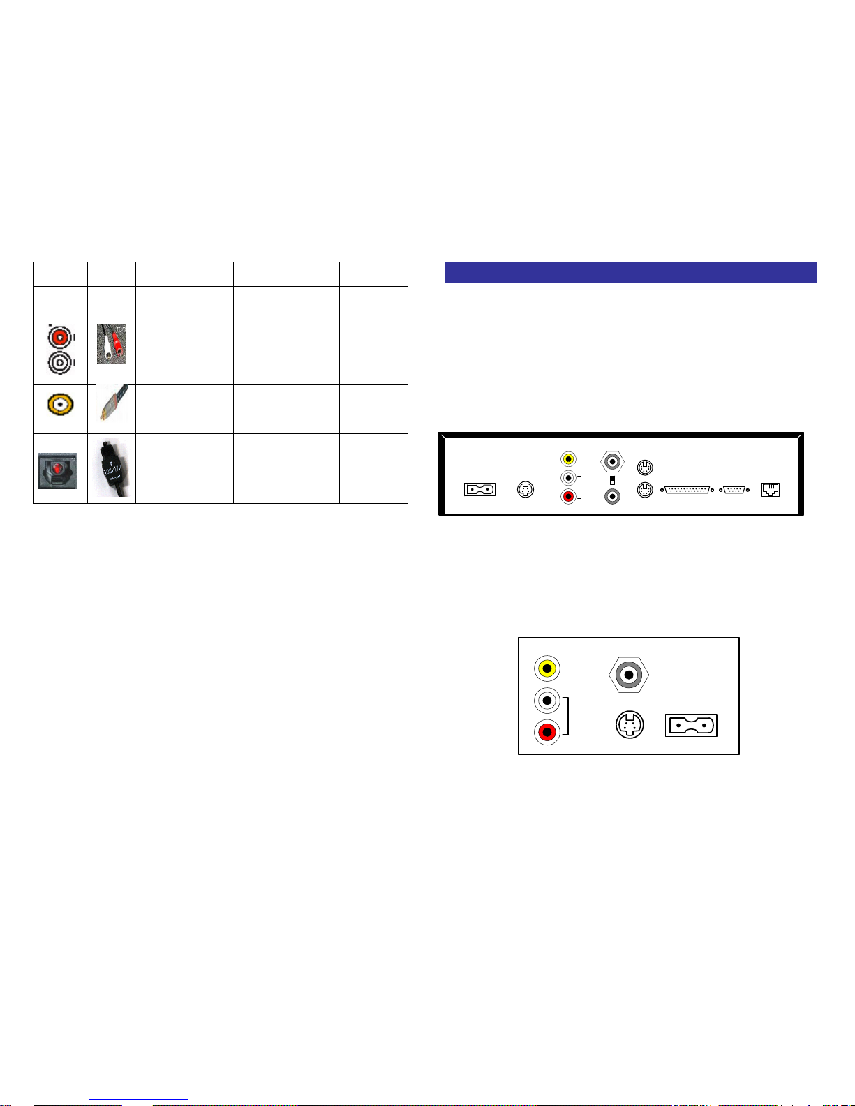
AUDIO
Jack Cable
Name
Typical Use
Level of
Video
Quality
RCA HDTV receivers,
cable boxes, Home
Theatre systems,DVD
players
Medium
S/PDIF HDTV receivers,
cable boxes, Home
Theatre systems,DVD
players
Very High
Optical Audio
a.k.a TOSLINK
cable
HDTV receivers,
cable boxes, Home
Theatre systems,DVD
players
Highest
TYPICAL SD SET TOP BOX (STB)
TICLES
Typical components
Set-top box (STB)
The same connections that are found on the back of most televisions and
VCRs are also found on the back of the STB, as shown below. In addition,
the network connection port is used to connect to the jack, hub or modem
through which the MAX service is received.
Ch 3
Ch 4
MOUSE
KEYBOARD
VIDEO OUT
AUDIO OUT
L
R
S-VIDEO
OUT
POWER
RF OUT
AERIAL IN
PARALLEL SERIAL
ETHERNET
TV set
This is a diagram of some of the typical connections found on the back of
most television sets. These are the connections that are used to receive
audio and video signals from a source. Most of today’s TVs also feature
additional A/V input connections on the front of the TV-set (not displayed
here).
VIDEO
IN
AUDIO
IN
L
R
S-VIDEO IN
POWER
ANT. IN
VCR
The connections that are found on the back of the most common VCRs are
similar to TV connections. All of the ‘IN’ and ‘VHF/UHF IN’ jacks are used
to receive a signal from the set-top box or from another source. Also note
the channel ¾ switch. When using the VHF/UHF jacks, this switch must be
set to the corresponding channel on the television in order for the
audio/video feed to be received.
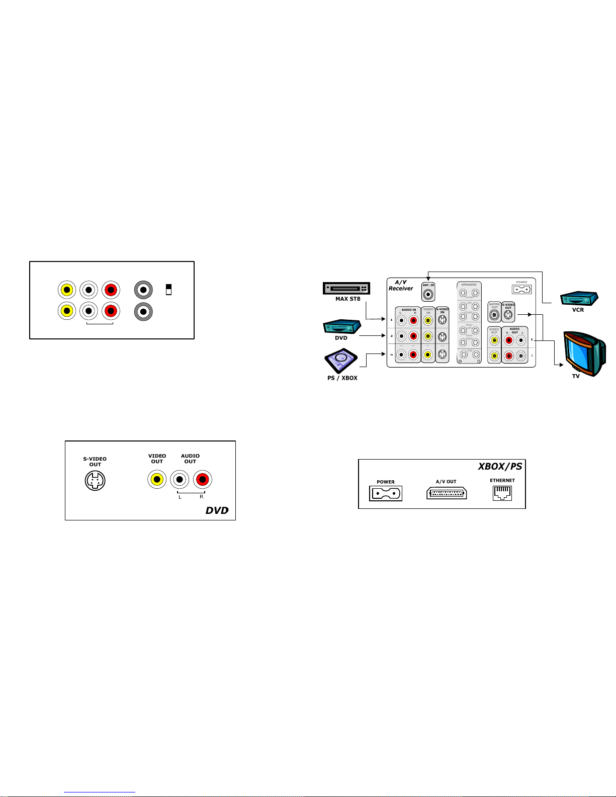
DVD player
Unlike VCRs, majority of today’s DVD players only feature output
connections. They include S-Video and RCA connections. It is
recommended that you use the S-Video output wherever possible for best
results.
Audio/Video receiver or home theater system
Most Audio/Video receivers function as concentrators for home theater
systems. By taking input from various sources (VCR, DVD, etc) receivers
direct the output to one or more common destinations like your TV-set
and/or audio system. Depending on the number and type of A/V inputs
that the receiver has, there may be many different ways of combining your
audio/video equipment together. This manual will review a few straight
forward examples.
AUDIO
L
R
VIDEO
IN
OUT
VHF/UHF
OUT
VHF/UHF
IN
Ch 3
Ch 4
Console gaming system
Although there are a great variety of console gaming systems, most of
them feature some type of RCA connectors. For example, both XBOX and
PlayStation require proprietary RCA cables, which come with the
respective products.

Connecting components
A. Basic configuration (TV + STB)
Coaxial
To connect the set-top box to the TV, place one end of the coaxial cable
into the bottom cable connector (RF OUT) of the set-top box and the other
free end into the VHF/UHF IN or ANT of the television set.
RCA cables
To connect the set-top box to the TV, plug one end of the A/V connector
(yellow) into the jack labeled VIDEO IN on the back of the television set.
Now plug the other end of the cable (yellow) into the VIDEO OUT on the
set-top box. Connect the left (white) audio cable into the left audio jack on
the television. Now plug the other end of the cable (white) into the left
audio jack on the set-top box. Repeat the last step for the last cable (red).
Now, to view a television broadcast, select Video 1 or Video 2 on the
television set.
S-Video (SVHS) cable
This configuration provides the best quality performance and is available
on most new models of television sets. To connect the set-top box to the
television, plug one end of the S-Video cable into the jack on the back of
the television labeled S-VIDEO IN (or SVHS IN). Plug the other end of the
S-Video cable into the S-VIDEO jack on the set-top box. Connect the two
audio cables (Left and Right) as described in the section above.
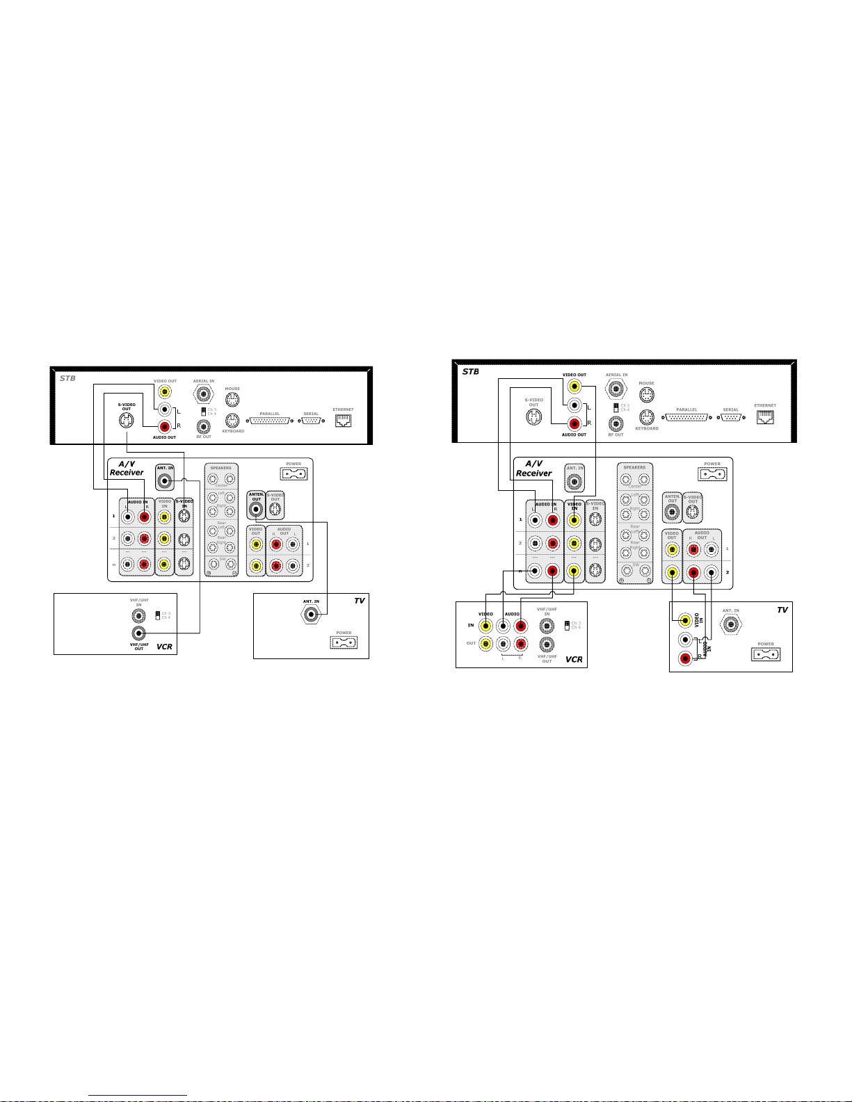
B. Adding VCR or DVD-player
Connection VCR with coaxial cables
To connect the set-top box to the TV and VCR using two coaxial cables,
attach one end of the coaxial cable to the RF OUT of the set-top box and
the other, free, end of the cable to the VHF/UHF IN jack of the VCR. Using
another coaxial cable, attach one of the ends to the VHF/UHF OUT jack of
the VCR and the other end of this cable to the WHF/UHF IN or ANT of the
television set.
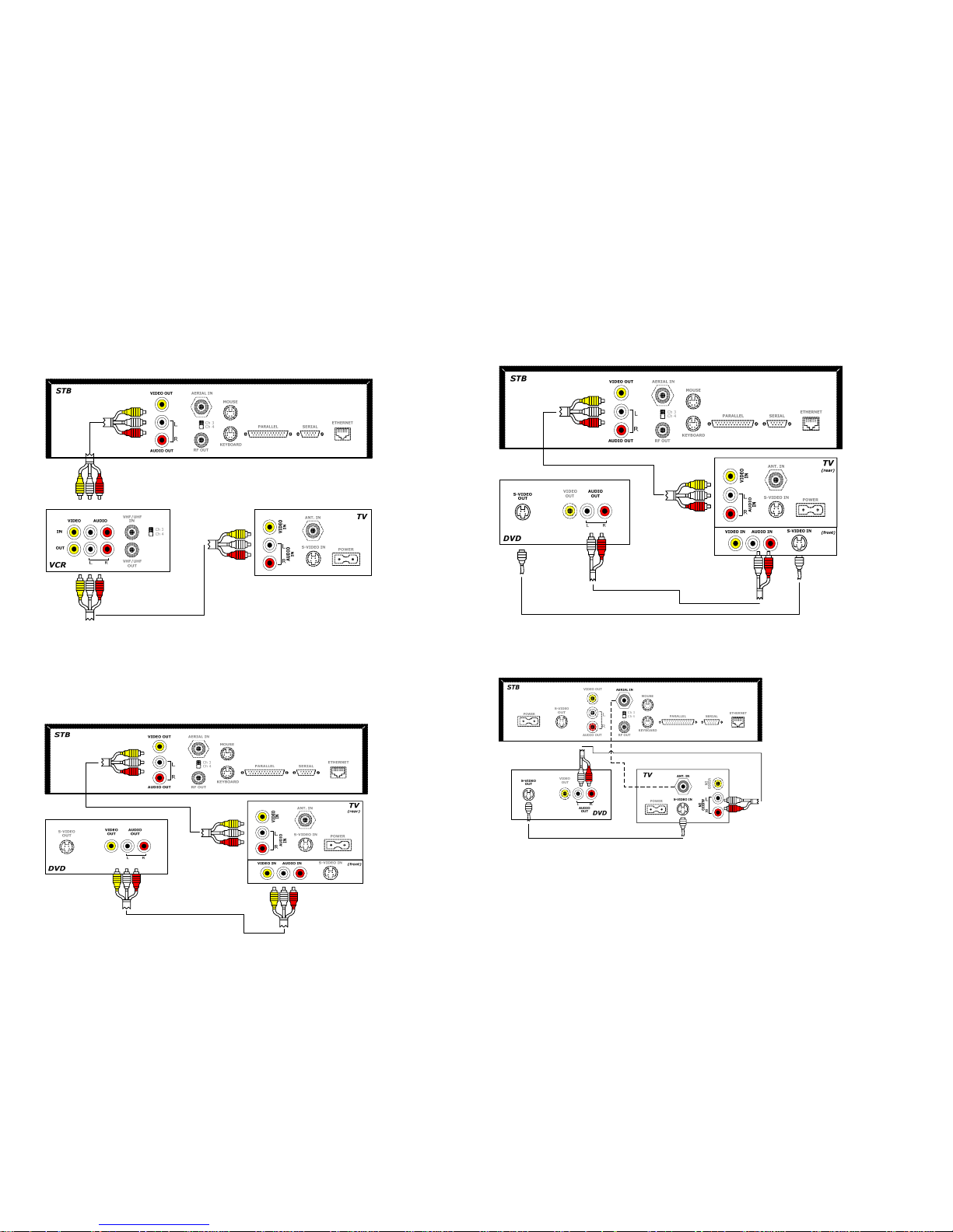
Connecting VCR with RCA cables
To connect the set-top box and VCR to the TV, you will need two sets of
RCA cables. Depending on how many RCA input links your TV supports, it
may be possible to connect both components directly into TV (see the
following section on connecting DVD-player with RCA cables). In the event
that your TV has only one RCA input, please consult the diagram below.
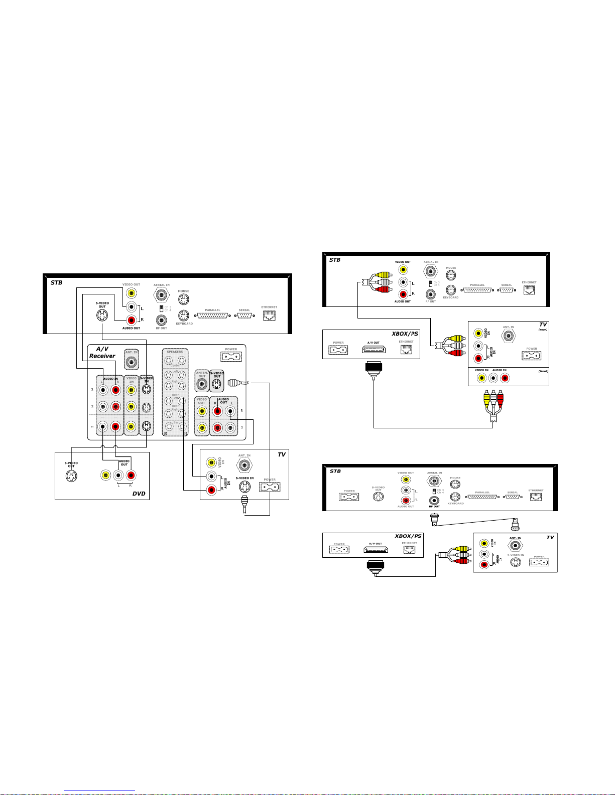
Connecting DVD-player with RCA cables
If your TV has enough A/V inputs, you may connect all of the components
directly into the TV. As in the diagram below indicates you will require two
sets of RCA cables. Furthermore, your VCR can be connected in the similar
fashion as the DVD-player below.
Connecting DVD-player with S-Video cable
Much like the previous diagram, if your TV has enough inputs, the
components may be connected directly to the TV. However, instead of
using the Video (yellow) jack, an S-video cable can be used to connect
both the DVD and STB to the TV-set.
Some older TV-sets may not have enough inputs to connect your STB and
DVD-player. Therefore it may be necessary to connect STB to the TV-set
with a coaxial cable (as indicated by the dotted line).
C. Audio/Video receiver or sound system
Coaxial cables
In this scenario a home theater system is used in conjunction with an
older VCR and TV-set, both of which support only RF connectors. Although
an S-video cable is used to connect STB to the A/V receiver, the picture
quality is limited by the TV’s RF input.
RCA cables
In this diagram both STB and VCR are connected to the receiver with RCA
cables. A DVD-player can be substituted for the VCR. However, it is
recommended to use S-Video connectors whenever possible. More devices
can be added by utilizing unused inputs on the Audio/Video receiver
and/or TV-set.
S-Video cables
This configuration provides the best quality performance. All components
are connected using S-video/RCA-audio cables combination. Any number
of additional devices maybe added to this set up. Additional devices can be
added in the future by utilizing unused inputs on the Audio/Video receiver
and/or TV-set itself.
IV. Adding a console gaming system
Scenario 1
Most of today’s console gaming systems require an RCA input to connect
to TV. Depending on the number and type of available inputs on your TV
you may have to either connect the console with RCA cables, or…
… with coaxial cable to the TV. If your TV lacks RCA inputs, please see FAQ
section of this manual for further information.
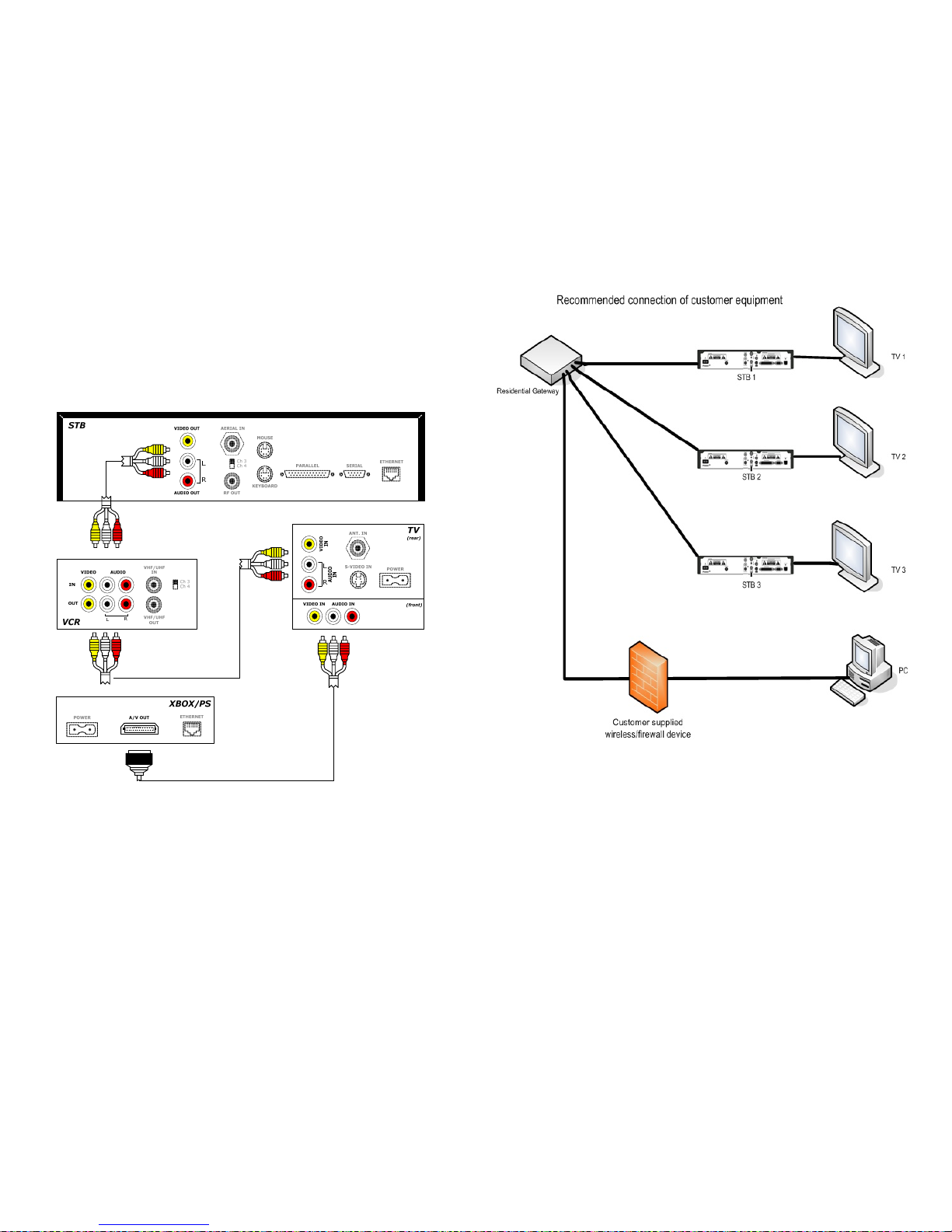
Scenario 2
If the TV has enough RCA inputs, the console should be connected directly
to the TV. In the event that all inputs are already taken it may be possible
to reposition some of the components. For example you can connect STB
and VCR in series as pictured below, thereby freeing up an input for your
favorite gaming system. If instead of a VCR you have a DVD-player that
does not have any inputs it may be required to temporarily disconnect on
of the unused components.
Scenario 3
When adding a console gaming system to an existing home theater
system, it is recommended to connect it directly to your TV, thereby
reducing the chance of accidentally disconnecting any of the components.
Furthermore, majority of newer TV’s feature an input panel on the front
just for such purposes. If, for whatever reason, your TV does not have an
available RCA input, you can connect the console directly to the home
theater receiver, much like you would a VCR or DVD-player.
Customer does not require a wireless or firewall device as the new
Residential Gateway provides both functions. However if they wish to use
their existing device it must be placed between the PC and the Gateway.

MOTOROLA HD/SD SET TOP BOX (STB)
Front Panel
KEY ITEM FUNCTION
1 POWER
If held for less than five seconds, turns the Max
set-top box on or off
If held for five seconds or longer, restarts the
set-top box
Lights Green when the Max set-top box is on
2 USB USB 2.0 connector
3 LINK Lights green when receiving a stream
4 HD
Lights blue when receiving a high-definition
program
5 RECORD
Lights red when you are recording a program
with the
DTVR. *** Applies to VIP 1216 only - not the
1200
6 MENU Displays the Home Page
7
Up and Down
arrow keys
Left and right
arrow keys
OK
Changes the channel up and down
Moves through the on-screen program guide and
menu
Selects channels or menu options
Rear Panel
KEY
ITEM FUNCTION
1 TO WALL Coaxial input (VIDEO IN)
2 HDMI
Connects to a high-definition TV or home theatre receiver with
an HDMI input (for a DVI input, use an HDMI-to-DVI adapter)
3 NETWORK Ethernet 10/100Base-T RJ-45 port
4 Y Pb Pr RCA-type component video outputs to an HDTV
5 S-VIDEO
High quality video output to a VCR or TV that accepts S-Video. It
carries video only; you must also connect to the TV or home
theatre receiver for audio.
6 OPTICAL S/PDIF audio output to a digital home theatre receiver
7
VIDEO
OUT
RCA-type video outputs to a TV, VCR, DVD recorder, or other
device
8
AUDIO
OUT
Left and right RCA-type stereo audio outputs L and R
9 TO TV
Coaxial output to a TV or VCR (VIDEO OUT)
10 USB USB 2.0 connector
11
POWER
+12 DC
Connector for the DC power adapter

Motorola Default Settings
TV Type
This setting affects how HD material will be displayed.
The Motorola VIP1200 has the default setting of 16:9. This is done
because nearly all HDTVs are at a 16:9 ratio and most HD content
is filmed in a 16:9 ratio. Setting 16:9 as the default ratio will
provide customers with the best HD viewing experience. If
customers have a 4:3 TV, HD content will be displayed with
letterboxing (or black bars at the top and bottom of the screen).
For example, CSI is filmed in a 16:9 ratio and will be displayed in a
16:9 ratio.
If you have a 4:3 ratio TV, you will see letterboxing at the top and
bottom of the TV screen.
YPbPr Output
YPbPr is also known as a Component connection.
This sets the format to be used by the Component, DVI or HDMI
connectors. (RF, Composite or S-Video will be for Standard TV
use.)
The output default is set to1080i to allow for the best possible
viewing experience for customers in an HD format.
4:3 Override
This tells the Set Top Box how it should display Standard Definition
Content.
The default setting is 480i. Standard Definition is displayed as it
would be on a SDTV on this setting. There will be Pillarboxing
(black bars at the sides) on the screen.
This will avoid the stretching and distortion of the picture to make
it fit on the 16:9 screen. The customer’s viewing will be clearer in
this mode.
It is always suggested that the default settings are left in place in
order avoid picture stretching and distortion that may occur if
these are changed.
The defaults will be configurable, if the customer wishes them to
change, but how to access the screens will not be obvious, to avoid
having a customer accidentally change the defaults and then not
know how to change them back.
YPbPr (or Component) and HDMI are both common connections for
HD Set Top Boxes. SaskTel Max will be using a Component
connection on installation because while many TVs have both
connector types, Component video is the most widely supported
HDTV connection. If customers choose to use another type of
connection, they will be responsible for providing it themselves.
Closed Captioning
The Set Top Box sends the Closed Captioning information to the
TV. If Closed Captioning is enabled on the Set Top Box, the
banners will appear, irrespective of what is set on the customer’s
TV.
Closed Captioning is disabled as a default setting on the Set Top
Box. This is done to accommodate most customers, as most
customers watch TV without Closed Captioning banners.
If the customer wishes to change the default setting on Closed
Captioning and enable the banners, they will find it off the Max
Portal Home Page, under Settings
These settings may also be adjusted through the television
menu. It is important to note that you may need to consult
the TV manual to adjust settings so that the picture is
displayed correctly
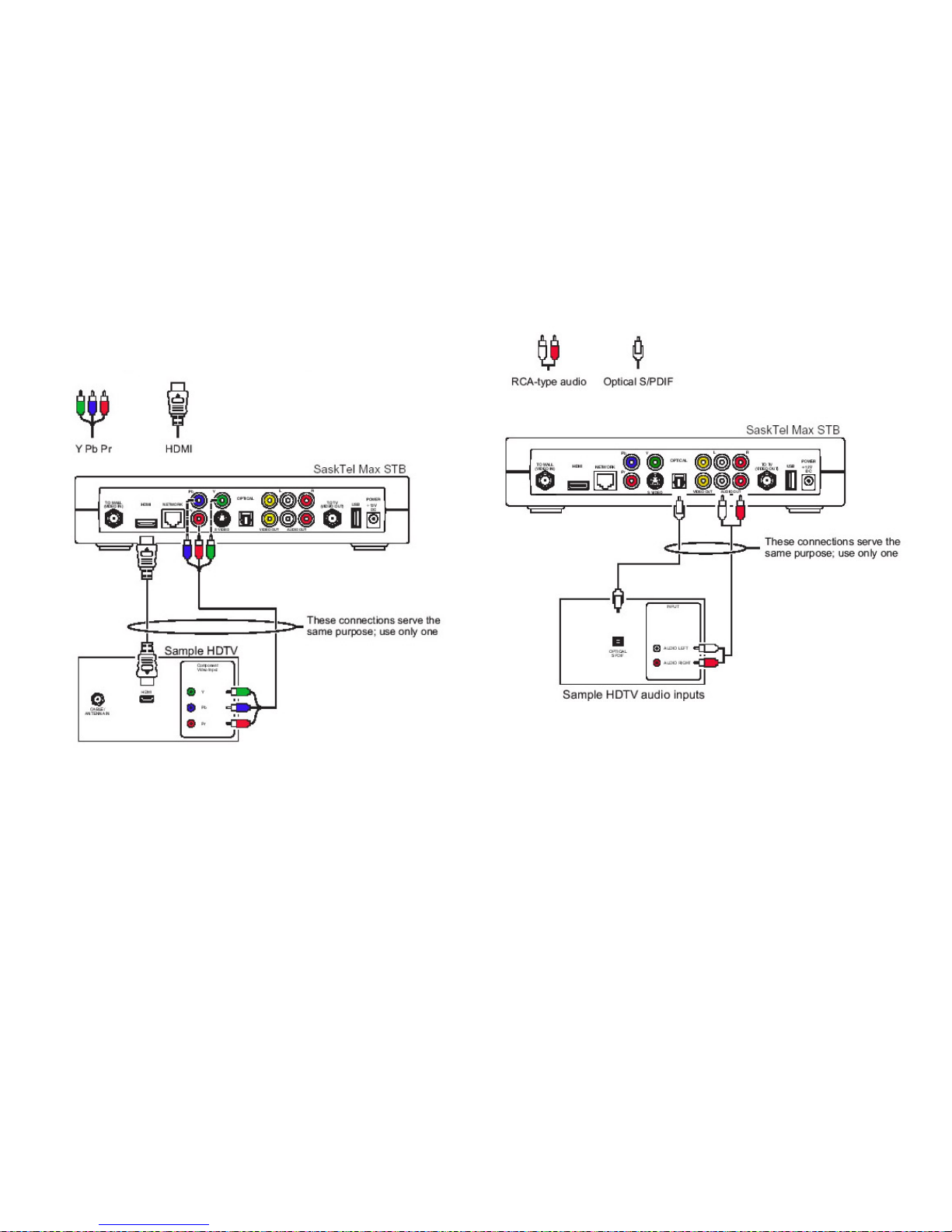
Connecting components
Connecting to an HDTV – Video Only
Connecting to an HDTV – Audio Only
 Loading...