

Page 1

Page 2

User’s manual
2
Tabel of contents
I. Safety ............................................................................................................................... 4
II. Description of the device ..................................................................................................... 5
III. Installation ...................................................................................................................... 5
IV. How to use the controller .................................................................................................. 8
IV.1. Principle of operation .................................................................................................. 8
IV.2. Stages of operation .................................................................................................... 8
IV.3. zPID control .............................................................................................................. 8
IV.4. Controller operation without zPID control ...................................................................... 9
IV.5. How to navigate ....................................................................................................... 10
V. Controller functions– main menu ........................................................................................ 10
V.1. Block diagram of the main menu. .................................................................................. 10
V. 2. Fire-up....................................................................................................................... 12
V. 3. Screen view ................................................................................................................ 12
V. 4. Fuel tank full .............................................................................................................. 12
V. 5. Temperature settings ................................................................................................... 12
V. 5.a) Pre-set CH temperature ......................................................................................... 12
V. 5.b) CH hysteresis ....................................................................................................... 12
V. 5.c) Pre-set DHW temperature ...................................................................................... 12
V. 5.d) DHW hysteresis .................................................................................................... 12
V. 5.e) Temperature of pump activation .............................................................................. 12
V. 5.f) Pre-set room temperature ...................................................................................... 13
V. 6. Manual mode .............................................................................................................. 13
V. 7. Operation settings ....................................................................................................... 13
V. 7.a) Feeding time ........................................................................................................ 13
V. 7.b) Pause time ........................................................................................................... 13
V. 7.c) Blow force ............................................................................................................ 13
V. 7.d) Operation in sustain mode ..................................................................................... 13
V. 7.e) Pause in sustain mode ........................................................................................... 13
V. 7.f) Fan in sustain mode .............................................................................................. 13
V.7.g) Fan speed in sustain mode ..................................................................................... 13
V. 8. Fuel granulation .......................................................................................................... 13
V. 9. Operation modes ......................................................................................................... 14
V. 9.a) House heating ...................................................................................................... 14
V. 9.b) Water tank priority ................................................................................................ 14
V. 9.c) Parallel pumps ...................................................................................................... 14
V. 9.d) Summer mode ...................................................................................................... 14
V. 10. Weekly control ......................................................................................................... 14
V. 11. Operation algorithm selection .................................................................................... 15
V. 12. Fitter’s menu ........................................................................................................... 15
V. 13. Service menu .......................................................................................................... 15
V. 14. Software version ...................................................................................................... 15
V. 14.a) Software update ................................................................................................ 16
V. 15. Factory settings ....................................................................................................... 16
Page 3

ST-550 zPID
3
VI. Controller functions - Fitter’s menu................................................................................... 16
VI.1. PID coefficient ......................................................................................................... 18
VI.1.a) CH boiler power coefficient .................................................................................. 18
VI.1.b) Fan correction bottom / Fan correction top ............................................................ 18
VI.2. PID supervision ........................................................................................................ 18
VI.3. Buffer parameters .................................................................................................... 18
VI.3.a) Buffer ............................................................................................................... 18
VI.3.b) DHW function .................................................................................................... 18
VI.3.c) Pre-set temperature top...................................................................................... 19
VI.3.d) Pre-set temperature bottom ................................................................................ 19
VI.4. Valve settings .......................................................................................................... 19
VI.4.a) Built-in valve, Additional valve 1 and 2 ................................................................. 19
VI.5. Additional pump 1 / Additional pump 2 ....................................................................... 23
VI.5.a) Algorithm selection ............................................................................................ 23
VI.5.b) Short circuit pump ............................................................................................. 23
VI.5.c) Floor pump ....................................................................................................... 23
VI.5.d) Circulating pump................................................................................................ 23
VI.6. Time settings ........................................................................................................... 24
VI.7. Date settings ........................................................................................................... 24
VI.8. Internet module ....................................................................................................... 24
VI.9. Fuel level calibration ................................................................................................. 27
VI.10. Language ................................................................................................................ 28
VI.11. Room regulator ........................................................................................................ 28
VI.12. External temperature correction ................................................................................. 28
VI.13. GSM module ............................................................................................................ 28
VI.14. Factory settings ....................................................................................................... 29
VII. ST-66P pellet module ...................................................................................................... 29
VIII. Protections ................................................................................................................. 32
VIII.1. Temperature alarm ................................................................................................ 33
VIII.2. Thermal protection of CH boiler (STB) ..................................................................... 33
VIII.3. Automatic sensor control ....................................................................................... 33
VIII.4. Protection against boiling of water in the CH boiler .................................................... 33
VIII.5. Temperature protection .......................................................................................... 33
VIII.6. Fuel feeder protection ............................................................................................ 33
VIII.7. Limt switch in the fuel tank .................................................................................... 33
VIII.8. Fuse .................................................................................................................... 33
IX. Maintenance .................................................................................................................. 34
Page 4
User’s manual
4
I. Safety
Before using the device for the first time the user should read the following regulations carefully. Not
obeying the rules included in this manual may lead to personal injuries or controller damage. The user’s
manual should be stored in a safe place for further reference. In order to avoid accidents and errors it
should be ensured that every person using the device has familiarized themselves with the principle of
operation as well as security functions of the controller. If the device is to be sold or put in a different
place, make sure that the user’s manual is there with the device so that any potential user has access to
essential information about the device.
The manufacturer does not accept responsibility for any injuries or damage resulting from negligence;
therefore, users are obliged to take the necessary safety measures listed in this manual to protect their
lives and property.
WARNING
• High voltage! Make sure the regulator is disconnected from the mains before performing any
activities involving the power supply (plugging cables, installing the device etc.)
• The device should be installed by a qualified electrician.
• Before starting the controller, the user shoud measure earthing resistance of the electric motors
as well as the insulation resistance of the cables.
• The regulator should not be operated by children.
WARNING
• The device may be damaged if struck by a lightning. Make sure the plug is discon-
nected from the power supply during storm.
• Any use other than specified by the manufacturer is forbidden.
• Before and during the heating season, the controller should be checked for condition of its ca-
bles. The user should also check if the controller is properly mounted and clean it if dusty or
dirty.
Changes in the merchandise described in the manual may have been introduced subsequent to its
completion on August 25th 2016. The manufacturer retains the right to introduce changes to the
structure. The illustrations may include additional equipment. Print technology may result in differences
in colours shown..
We are committed to protecting the environment. Manufacturing electronic devices
imposes an obligation of providing for environmentally safe disposal of used electronic
components and devices. Hence, we have been entered into a register kept by the
Inspection For Environmental Protection. The crossed-out bin symbol on a product
means that the product may not be disposed of to household waste containers.
Recycling of wastes helps to protect the environment. The user is obliged to transfer
their used equipment to a collection point where all electric and electronic components
will be recycled.
Page 5

ST-550 zPID
5
II. Description of the device
ST–550zPID temperature regulator is intended to control CH boiler with a screw feeder. Due to its
advanced software it offers a range of functions:
• Control of the fan and the feeder
• Control of CH pump
• Control of DHW pump
• Control of two additional pumps
• Control of two mixing valves actuators
• Possibility of connecting a room regulator with traditional or RS communication
• Possibility of connecting ST-65 GSM module
• Built-in Ethernet module enabling the user to view certain parameters and control
certain functions via the Internet
• Possibility of controlling two valves via additional modules (e.g. ST-431N)
Controller equipment:
• CH temperature sensor
• Feeder temperature sensor (protection)
• Floor temperature sensor
• DHW sensor
• Temperature protection (bimetallic mini sensor)
• Supply cable
• Pump supply cables
• Hall-sensor of the fan
• Feeder flap limit switch
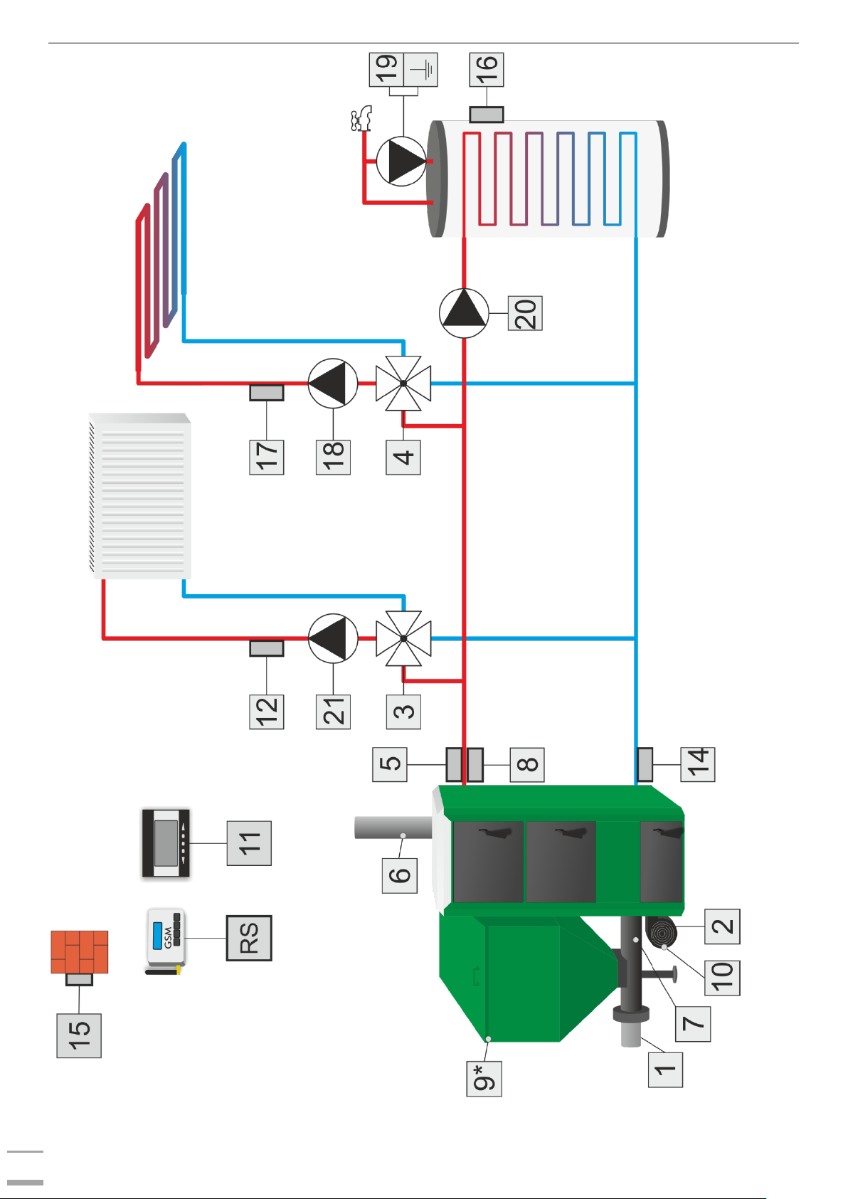
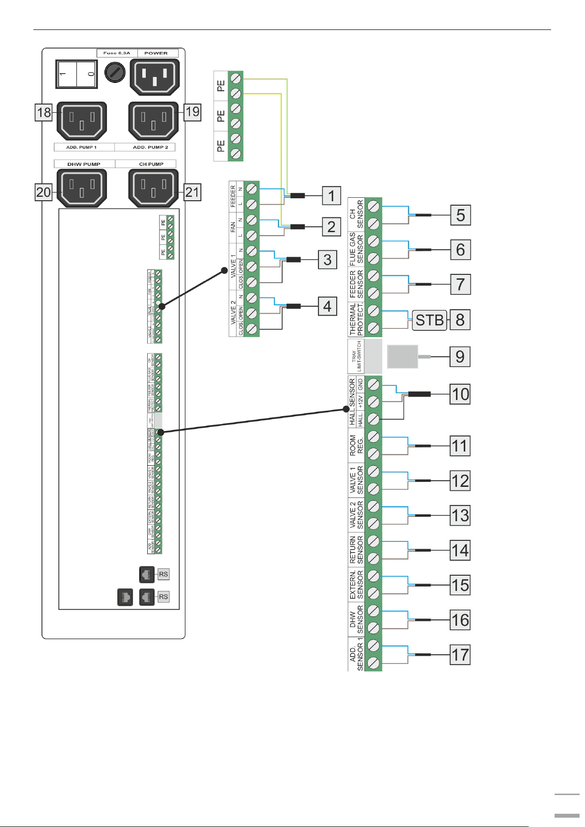
III. Installation
The controller should be installed by a qualified person.
WARNING
Risk of fatal electric shock from touching live connections. Before working on the controller
switch off the power supply and prevent it from being accidentally switched on.
WARNING
Incorrect connection of the wires may lead to controller damage!
Page 6
User’s manual
6
Page 7
ST-550 zPID
7
Page 8

User’s manual
8
IV. How to use the controller
IV.1. Principle of operation
The regulator controls the fan and the fuel feeder operation so that the pre-set temperature of the CH
boiler and the water tank is reached. Additionally, it controls CH and DHW pump operation activating
them once a pre-defined temperature of the CH boiler has been reached.
IV.2. Stages of operation
Fire-up – this phase is initiated when the flue gas temperature reaches a pre-set value and does not
drop below this value for 30seconds (default fire-up time).
Operation – when the fire-up phase has been completed, the controller enters operation mode and the
display shows the message ‘PID: OPERATION’. It is the primary mode of controller functioning when the
blow force and fuel feeding are regulated with PID algorithm, oscillating around the pre-set temperature
defined by the user. When the temperature increases unexpectedly by more than 5oC above the pre-set
value, the supervision mode is activated.
Supervision mode – this mode is activated automatically when the temperature exceeds the pre-set
value by more than 5oC in operation mode. In such a case, the controller disables PID control and uses
manual settings (according to parameters defined in the fitter's menu).The display shows the following
message: ‘PID: SUPERVISION’
IV.3. zPID control
ST-550zPID is a controller with continuous output signal, using zPID algorithm. This type of controller
calculates the blow force on the basis of CH boiler temperature and the flue gas temperature measured
at the CH boiler outlet. The fan operates continuously and the blow force depends on the CH boiler
temperature, the flue gas temperature as well as the difference between these parameters and their preset values. One of the greatest advantages of zPID regulators is their ability to maintain a stable pre-set
temperature without unnecessary overregulation and oscillations.
Apart from zPID control, the controller operation is adjusted on the basis of the the readings from
the air flow sensor mounted on the fan.
Using this type of regulator with a flue gas sensor helps to reduce fuel costs by up to several percent.
Moreover, it ensures stable temperature of output water thus prolonging the life of the heat exchanger
(of the CH boiler). Flue gas temperature control results in low emission of dust and environmentally
harmful gases. Flue gas heat is not disposed of through the chimney, but it is utilised for heating
purposes.
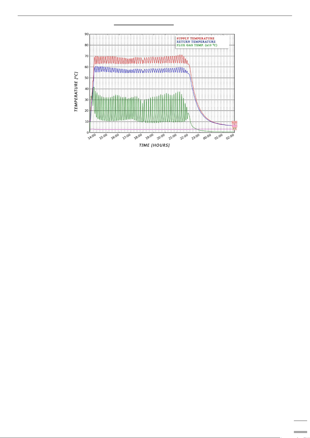
TEST RESULTS - TECH controller with PID control:
Page 9
ST-550 zPID
9
TEST RESULTS - TECH controller without PID control:
IV.4. Controller operation without zPID control
zPID control may be disabled at any time using Operation algorithm selection parameter.
Additional submenu will appear in the controller menu, allowing the user to configure boiler operation
parameters.
Once zPID control is disabled, the principle of operation is changed - after the fire-up stage the
controller enters operation mode which is followed by sustain mode:
Operation – once the controller is switched on, it enters operation mode and OPERATION appears on
the display. It is the primary mode of controller operation in which the fan operates continuously and the
fuel feeder operation is adjusted according to user’s settings. The user defines both the operation time
and pause time.
Sustain mode – this mode is activated automatically if the temperature is equal or higher than the preset temperature value. Fuel feeding process slows down in order to smoothly reduce the temperature of
the circulating water. SUSTAIN appears on the display. In order for the temperature to decrease properly,
it is necessary to configure operation and pause time in sustain mode as well as the fan speed.
Page 10
User’s manual
10
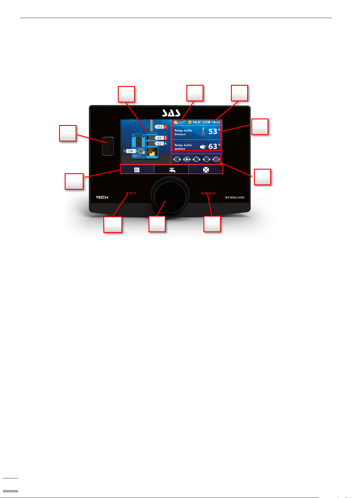
IV.5. How to navigate
During standard operation of the controller, graphic display shows the main page.
By pressing MENU button the user enters the first level menu. In order to move on to the next option,
twist the pulser knob. Press the knob to select an option. Follow a similar procedure when adjusting
parameters. In order for the changes to be saved, use the pulser knob to select CONFIRM. In order not
to introduce any changes, use the pulser knob to select CANCEL. In order to leave the menu, use EXIT
button.
1. USB port
2. Panel showing current parameters of the sensors and the fan
3. CH boiler operation stage
4. Current time
5. Right parameter panel – use pulser knob to switch between CH boiler parameters and DHW or
valve parameters (if activated).
6. Operation status bar - it displays icons indicating all devices which are currently active:
- fan and its speed (%); if Hall sensor of the fan is active, letter H is displayed;
- feeder; if burning without feeder option is active, a crossed out feeder icon is displayed.
- CH pump
- DHW pump
- additional pump 1
- additional pump 2
7. Enter the controller menu. While viewing the controller functions use this button to return to the
main screen view.
8. Pulser knob. Twist the knob in the main screen view to change the parameter view or press it to
edit the selected parameter. While viewing the menu options use the knob to move on to the next
function or configure CH boiler operation parameters.
9. EXIT button
10. Active operation panel bar:
- CH boiler
- DHW
- built-in valve (if switched on)
- additional valves (if switched on; additional valve modules e.g. ST-431N are required).
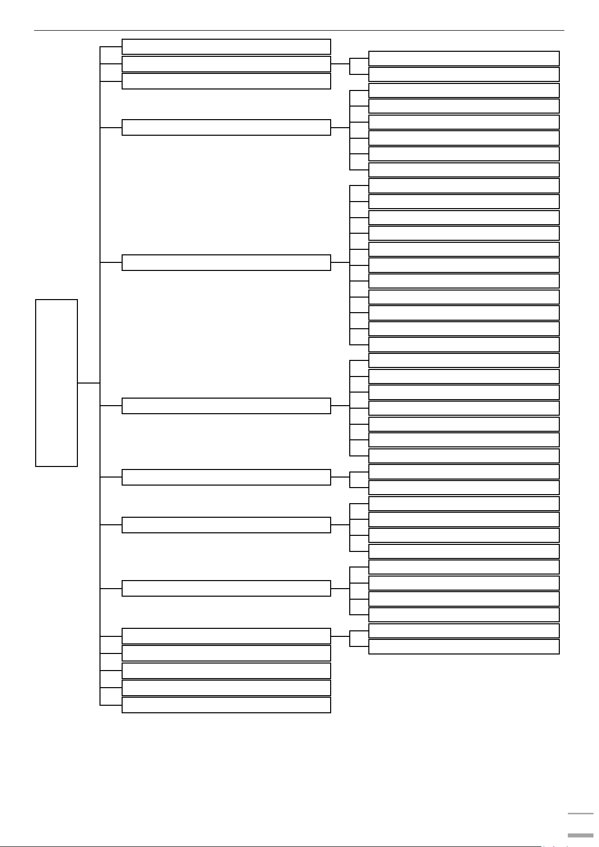
V. Controller functions– main menu
V.1. Block diagram of the main menu.
Due to multiple functions offered by the controller, the menu is divided into Main Menu and Fitter’s Menu.
The main menu allows the user to set the basic controller options such as pre-set temperature values,
operation modes, screen view etc.
6
7
5 4 3
2
1
10
8
9
Page 11
ST-550 zPID
11
*Parameters available in the controller menu only if the additional valve module has been connected and
module registration process has been completed in the additional valve menu.
**Submenu available only if Operation without PID is selected.
***Parameter available only if TECH room regulator with RS communication has been connected and
activated.
Main menu
Fire-up
Screen view
Standard screen
Test screen
Fuel tank full
Temperature settings
Pre-set CH temperature
CH hysteresis
Pre-set DHW temperature
DHW hysteresis
Pump activation temperature
Pre-set room temperature***
Manual mode
Fan
Blow force
Feeder
CH pump
DHW pump
Additional pump 1
Additional pump 2
Built-in valve 1
Built-in valve 2
Additional valve 1*
Additional valve 2*
Operation settings**
Feeding time
Pause time
Blow force
Operation in sustain mode
Pause in sustain mode
Fan in sustain mode
Fan speed in sustain mode
Fuel granulation
Fine granulation
Coarse granulation
Operation modes
House heating
Water tank priority
Parallel pumps
Summer mode
Weekly control
Mode
Set mode 1
Set mode 2
Delete settings
Operation algorithm
PID
Operation without PID
Fitter’s menu
Service menu
Software version
Factory settings
Page 12

User’s manual
12
V.2. Fire-up
This function enables the user to easily fire-up the CH boiler. After initiating the fire manually (preparing
the furnace and starting the fire), the user activates automatic fire-up phase in the controller menu. The
controller conducts the fire-up process maintaining the blow and gradually feeding fuel. Thanks to
optimum parameters, CH boiler smoothly switches to operation mode.
Once the CH boiler entered operation mode, instead of Fire-up function the menu displays
Damping function, which may be used to activate damping process.
V.3. Screen view
This function is used to choose between standard screen view and test screen view (secured with a code).
V.4. Fuel tank full
This function should be used after the fuel tank has been fully filled, in order to reset the fuel consumption
percentage to 100% (the value displayed in the top right-hand corner of the main screen, below the
clock).
NOTE:
Before using this function for the first time it is necessary to calibrate the fuel feeder operation
in the fitter’s menu.
V.5. Temperature settings
V.5.a) Pre-set CH temperature
This option is used to define the pre-set CH boiler temperature. The setting rage is 45⁰C do 80⁰C.
The pre-set temperature may also be changed with the use of weekly control function. The pre-
set temperature is the sum of all these values but within the range of 45⁰C do 80⁰C.
V.5.b) CH hysteresis
This option is used to set the hysteresis of the pre-set temperature. It is the difference between the
temperature of entering the sustain mode and the temperature of restoring operation mode (for example:
when the pre-set temperature is 60 ºC, the hysteresis is 3ºC, entering sustain mode takes place at the
temperature of 60 ºC whereas returning to the operation mode takes place at 57 ºC).
V.5.c) Pre-set DHW temperature
This function is used to define the pre-set temperature of the domestic water (this function is inactive
when house heating mode is selected). This value may be adjusted directly from the main screen view.
After the tank water reaches this temperature, DHW pump is disabled. The pump will be enabled again
when the temperature drops below the pre-set temperature by a pre-defined value.
V.5.d) DHW hysteresis
This option is used to set the hysteresis of the pre-set water tank temperature. It is the difference
between the pre-set temperature (desired temp. of the water tank when DHW pump is switched off) and
the temperature at which DHW pump is activated again (for example: when the pre-set temperature is
55 ºC, the hysteresis is 5ºC, DHW pump is switched off and CH pump is enabled when the pre-set
temperature of 55 ºC is reached. DHW pump is activated again when the temperature drops to 50 ºC).
V.5.e) Temperature of pump activation
This option is used to define the temperature of CH pump and DHW pump activation (temperature
measured on the CH boiler). Below this temperature value both pumps remain inactive whereas above
this value the pumps are enabled and operate according to the operation mode (see: pump operation
modes).
Page 13

ST-550 zPID
13
V.5.f) Pre-set room temperature
Once a room regulator with RS communication has been connected and activated in the controller menu
(Fitter’s menu/Room regulator), the user may adjust the pre-set room temperature.
V.6. Manual mode
For the user's convenience, the regulator offers manual mode function. In this function, each executive
device may be activated and deactivated independently of others. It is an easy way of checking if the
following devices work properly: feeder, blow (fan), CH pump, DHW pump, additional pump 1, additional
pump 2, built-in valve1, built-in valve 2, valve 1, valve 2). Additionally, the user may adjust the fan speed
in manual operation mode using blow force function.
V.7. Operation settings
NOTE: This submenu is available only when PID control is disabled - see: Controller operation
without zPID control.
V.7.a) Feeding time
This option is used to set the operation time of the fuel feeder. It should be adjusted to the type of fuel
and CH boiler used.
V.7.b) Pause time
This option is used to set the pause time of the feeder. The length of the pause should be adjusted to
the type of fuel used.
Incorrect pause time may result in inefficient operation of the CH boiler, i.e. unburnt coal left or failure
to reach the pre-set temperature of the CH boiler. Appropriate pause time ensures efficient operation of
the CH boiler.
V.7.c) Blow force
This function is used to control the fan speed. The setting range is 1-100% (it may be regarded as fan
gears). The higher the gear is, the faster the fan works. 10% is the minimum fan speed whereas 100%
is the maximum fan speed.
Initially the fan always operates at a full speed, which enables successful activation even if the
motor is dusty.
V.7.d) Operation in sustain mode
This option is used to set the operation time of the feeder and the fan when the CH boiler operates in
sustain mode.
V.7.e) Pause in sustain mode
This option is used to set the fuel feeding pause time when the CH boiler operates in sustain mode.
Incorrect setting of pause and operation time may result in farther temperature increase, unintended CH
boiler damping or lead to fuel ignition hazard in the fuel tank.
V.7.f) Fan in sustain mode
This option is used to set the fan operation and pause time in sustain mode.
V.7.g) Fan speed in sustain mode
This option is used to set appropriate fan gear (blow force) in sustain mode.
V.8. Fuel granulation
This function is used to choose one of the two levels of fuel granulation: coarse or fine. For each level
there is suitable blow force and fuel feeding frequency programmed.
Page 14

User’s manual
14
V.9. Operation modes
V.9.a) House heating
When this function is selected, only the house is heated. CH pump is activated when the temperature is
above the pump activation threshold (factory setting). Below this temperature value (minus 2OC –
hysteresis) the pump is disabled.
V.9.b) Water tank priority
In this mode, the DHW pump is activated first and it operates until the pre-set DHW temperature is
reached. After the pre-set temperature has been reached, the pump is switched off and the CH pump is
activated.
CH pump operates continuously until the water tank temperature drops below the pre-set value
minus DHW hysteresis. Then, the CH pump is disabled and the DHW pump is activated.
In this mode, the fan and the feeder operation is limited to 72 OC at the CH boiler in order to prevent the
CH boiler from overheating.
WARNING:
Return valves should be installed on the circuits of the CH and DHW pumps. The valve on
DHW pump prevents hot water from being sucked out of the water tank.
V.9.c) Parallel pumps
In this mode, both pumps are activated simultaneously above the pre-set activation temperature (default
setting: 40 ºC).
CH pump operates all the time whereas DHW pump is disabled when the pre-set water tank temperature
is reached.
V.9.d) Summer mode
In this mode, CH pump is switched off and DHW pump is enabled above the pump activation threshold
(default setting: 40OC) and operates all the time above this threshold.
In summer mode the user defines only the pre-set temperature of the CH boiler which heats the
domestic hot water (this value also serves as the pre-set water tank temperature). After this function
has been activated, the screen displays current CH temperature and two DHW temperature values (the
current temperature value and the pre-set one).
V.10. Weekly control
Weekly control function enables the user to program changes of the pre-set CH boiler temperature
(CH weekly control) or water tank temperature (DHW weekly control) for particular hours and days of
the week.
In order to activate this function, select mode 1 or mode 2. Detailed settings of each mode are
available further in the submenu: Set mode 1 and Set mode 2.
Once a given mode is selected, the main screen displays the value of current temperature deviation
(below the pre-set CH temperature, alternately with Pre-set) informing the user that the function is
active.
How to change weekly control settings:
ST-491 controller enables the user to program weekly control function in two modes:
MODE 1 – the user sets the temperature deviations for each day of the week separately;
MODE 2 – the user sets the temperature deviations for all working days (Monday-Friday) and for the
weekend (Saturday-Sunday) separately.
How to configure mode 1:
In order to configure mode 1, select Set mode 1 – the display shows the panel with particular days of
the week.
Once a given day of the week is selected, the screen shows the editing panel – the upper line shows
current deviation, the lower line shows the time period. Twist the pulser knob to change the time
period. In order to edit the deviation value, press the pulser knob and select Change.
In order to copy the setting for the next time period, press the pulser knob and select Copy.
Page 15

ST-550 zPID
15
Example:
Monday
set: 3
00
AM, temp -100C (weekly control setting– 100C)
set: 4
00
AM, temp -100C (weekly control setting– 100C)
set: 5
00
AM, temp -100C (weekly control setting– 100C)
In this case, if the pre-set temperature of the CH boiler is 60
0
C, from 3
00
AM to 6
00
AM on
Monday the pre-set temperature will drop by 100C, so it will be 500C.
How to configure mode 2:
In order to configure mode 2, select Set mode 2 – the display shows a panel with two day groups –
Monday-Friday and Saturday-Sunday. Select the group to be edited and follow the same procedure as
with mode 1.
Example:
Monday-Friday
set: 3
00
AM, temp -100C (weekly control setting – 100C)
set: 4
00
AM, temp -100C (weekly control setting – 100C)
set: 5
00 AM
, temp -100C (weekly control setting – 100C)
Saturday-Sunday
set: 4
00
PM, temp 50C (weekly control setting +50C)
set: 5
00
PM, temp 50C (weekly control setting +50C)
set: 6
00
PM, temp 50C (weekly control setting +50C)
In this case, if the pre-set temperature of the CH boiler is 60
0
C, on each weekday (Monday –
Friday) from 300AM to 600AM the pre-set temperature will drop by 100C, so it will be 500C. During the
weekend, from 4
00
PM to 7
00
PM the pre-set temperature of the CH boiler will increase by 50C, so it will
be 650C.
NOTE
In order for the weekly control to function properly it is necessary to set current time and
day of the week in Fitter’s menu >> Clock.
Delete data
This function enables the user to delete all weekly control settings.
V.11. Operation algorithm selection
This function is used to select the operation algorithm. If the user does not want to use zPID control
function, it may be disabled by selecting Operation without PID.
V.12. Fitter’s menu
Functions available in this menu are described in detail in the following sections of this manual.
V.13. Service menu
In order to enter the service menu of ST-550zPID controller, it is necessary to enter a 4-digit code
provided by TECH company staff.
V.14. Software version
W funkcji tej użytkownik może sprawdzić jaką wersję programu posiada sterownik. Po przekręceniu
impulsatora na ekranie wyświetlona zostanie informacja o wersji programowej modułów dodatkowych
sterujących zaworem.
Page 16

User’s manual
16
V.14.a) Software update
• Software update should be conducted when the CH boiler is damped.
• The memory stick which is going to be used to save the set-up file should be empty (prefer-
ably formatted)
• Make sure that the file saved on the memory stick has exactly the same name as the down-
loaded file so that it is not overwritten.
Insert the memory stick with the software into the controller USB port.
Reset the device by unplugging it and plugging it back in.
When the controller starts again, wait until the software update process starts.
o Once restarted, the controller display shows the starting screen.
o Software update starts automatically.
o During installation process colourful stripes appear on the screen illustrating the installation
progress.
o Once the installation process is completed, the display shows the main screen.
Once the software update has been completed, you can remove the memory stick from the USB
port.
The software update of ST-66P module may be conducted in a similar way by inserting the memory
stick with the software into the USB port of the additional module.
V.15. Factory settings
The controller is pre-configured for operation. However, the settings should be customized to the user's
needs. Return to factory settings is possible at any time. When the factory settings option is activated,
all customized settings of the CH boiler (saved in the user's menu) are lost and replaced with the
manufacturer's settings. Then, the parameters may be customized anew.
VI. Controller functions - Fitter’s menu
Fitter’s menu should be accessed by a qualified person. It is used to configure additional functions of the
controller such as CH boiler parameters, additional valves, additional pumps etc. as well as advanced
settings of basic functions (such as built-in valve parameters).
Block diagram of fitter’s menu is presented below:
Page 17

ST-550 zPID
17
*Submenu available only when Operation with zPID control is selected
**Submenu available only when Operation without zPID control is selected
***Submenu available only when additional module ST-66B is used
Fitter’s menu
PID coefficient*
CH boiler power coefficient
Fan correction top
Fan correction bottom
PID supervision*
Feeding time
Feeding pause
Fan operation time
Fan pause time
Fan revolutions
Buffer parameters***
Buffer
DHW function
Pre-set bottom buffer temp.
Pre-set top buffer temp.
Valve settings
Additional pump 1
Operation algorithm selection
Short circuit pump
Floor pump
Circulating pump
Additional pump 2
Operation algorithm selection
Short circuit pump
Floor pump
Circulating pump
Fuel level calibration
Full tank
Empty tank
Time settings
Date settings
Internet module Module ON
Room regulator
CH pump control
CH boiler control
TECH regulator
External temperature correction
Language
GSM module
OFF
ON
Factory settings
Page 18

User’s manual
18
VI.1. PID coefficient
NOTE
This submenu concerns CH boiler operation with PID control and t is available only when
zPID control is active.
VI.1.a) CH boiler power coefficient
CH boiler power coefficient serves to control the feeder and fan operation at the same time. 100% is the
default value but it may be adjusted within the range of 50-110%. Once a change is introduced, the
upper limit of zPID parameters is moved (operation/pause time of the feeder and blow force). The lower
limit of parameters remains unchanged.
VI.1.b) Fan correction bottom / Fan correction top
This function is used to adjust the fan speed. If the blow force is too low/high, the coefficient should be
adequately increased/decreased in order to ensure efficiency.
The user may adjust the fan speed for both minimum and maximum CH boiler power indicated by zPID
(Fan correction bottom and Fan correction bottom parameters).
VI.2. PID supervision
NOTE
This submenu concerns CH boiler operation with PID control and t is available only when zPID
control is active.
In this function the user configures the combustion parameters for the situation when the CH boiler
temperature exceeds the pre-set value by 5°C. If Damping mode function is selected, the damping
process is initiated when the pre-set temperature value is exceeded by 5°C. Once the process is
completed, the controller constantly monitors the CH boiler temperature. If it drops by a pre-defined
vale, the fire-up process is initiated again.
NOTE
Damping mode concerns only pellet-fired CH boilers controlled with the use of an additional
ST-66P module.
The remaining options should be configured if the user does not want the CH boiler to be damped when
the controller enters supervision mode. The user sets fuel feeding time, feeding pause as well as fan
operation and pause time during fuel feeding (blow-by gear)
The function is deactivated automatically when the CH temperature drops to the pre-set value.
VI.3. Buffer parameters
NOTE
Function available only when ST-66B module is used.
These parameters enable the user to configure controller operation settings in the case of heating
systems with a buffer.
VI.3.a) Buffer
Once buffer function is activated (by selecting ON) , CH pump serves as pump of the buffer in which two
sensors are installed: upper (C1) and lower (C2). The pump remains active until the pre-set temperature
of buffer bottom is reached. When the temperature drops below the pre-set buffer top temperature, the
pump is activated again.
VI.3.b) DHW function
If buffer is used in the heating system, it is necessary to specify how the water tank is connected:
- from CH boiler – the heating system in which DHW tank is connected directly to the CH boiler (a
separate circuit).
- from buffer – the heating system in which DHW tank is built in or connected to the buffer.
Page 19

ST-550 zPID
19
VI.3.c) Pre-set temperature top
This function enables the user to define the pre-set temperature for the upper part of the buffer (sensor
should be placed in the upper part of the tank). After this value is reached, the pump is disabled (provided
that the pre-set buffer temperature bottom has also been reached).
VI.3.d) Pre-set temperature bottom
This function enables the user to define the pre-set temperature for the lower part of the buffer (sensor
should be placed in the lower part of the tank).
VI.4. Valve settings
VI.4.a) Built-in valve, Additional valve 1 and 2
These options are used to configure operation of the built-in valve. The built-in module controls two
valves without the need to use additional devices. It the heating system requires other devices, an
additional module controlling the valve (e.g. ST-431N) may be connected to the ST-550zPID controller.
The parameters included in the submenus Valve 1 and Valve 2 are intended for controlling such valves.
In the case of valves 1 and 2, it is necessary to register in order for the valve to operate correctly. To
register the valve, enter the module number (placed on the casing) and configure a few parameters.
There is a range of parameters intended for configuring the operation of the valves and adjusting it to
the user’s needs. Both the parameters of the built-in valve and the parameters of the valves are similar,
which is illustrated by the following block diagrams:
Built
-in valve 1, 2
Valve status
ON
OFF
Pre-set valve temperature
Temperature control
Opening time
Single stroke
Minimum opening
Valve type
CH valve
Floor valve
Weather-based control
ON
OFF
Pre-set temperature for -20⁰C
Pre-set temperature for -10⁰C
Pre-set temperature for 0⁰C
Pre-set temperature for 10⁰C
Room regulator
Room regulator
Room reg. temp. lower
Room temperature difference
Change of pre-set valve temperature
Return protection
ON
OFF
Minimum return temperature
Maximum temperature
Valve pump
Operation modes
Pump activation temperature
Factory settings
Page 20

User’s manual
20
Registration
Option available only for valve 1 and valve 2.
This function is used by the fitter to enter the serial number of the module controlling the threeway valve actuator (a 5-digit number given on the module casing). Without this number the function
remains inactive.
Valve status
This function allows the user to deactivate the valve temporarily without the need to remove it
altogether. After re-activating the valve, it is not necessary to register again.
Pre-set valve temperature
This function is used to define the pre-set temperature of the valve. The setting range differs depending
on the valve type. The pre-set temperature value may be adjusted directly from the main screen view
by twisting the pulser knob.
Valve1, Valve 2
Registration
Valve status
ON
OFF
Pre-set valve temperature
Temperature control
Opening time
Single stroke
Maximum opening
Valve type
CH valve
Floor valve
Weather-based control
ON
OFF
Pre-set temperature for -20⁰C
Pre-set temperature for -10⁰C
Pre-set temperature for 0⁰C
Pre-set temperature for 10⁰C
Sensor selection
Room regulator
Room regulator
Room reg. temp. lower
Change of pre-set valve temperature
Room temperature difference
Return protection
ON
OFF
Minimum return temperature
Maximum temperature
External sensor correction
Factory settings
Valve removal
Valve pump
Operation modes
Pump activation temperature
Page 21

ST-550 zPID
21
Temperature control
This parameter determines the frequency of water temperature measurement (control) behind the CH
or DHW valve. If the sensor indicates a change in temperature (deviation from the set value), then the
electric valve will open or close by the set stroke, in order to return to the pre-set temperature.
Opening time
This parameter defines the time needed for the valve actuator to open the valve from 0% to 100%
position. This value should be adjusted to the value given on the actuator rating plate.
Single stroke
This function is used to define the maximum single stroke (opening or closing) that the valve may make
during one temperature sampling.
Minimum opening
This function is used to set the minimum value of valve opening. The valve does not close any further.
Valve type
This option is used to select the type of valve used.
For the function of weather control to be active, the external sensor mustn't be exposed to sunlight or
influenced by the weather conditions.
After it is installed in an appropriate place, weather-based control function needs to be activated in the
controller menu.
For the valve to operate correctly, the user defines the pre-set temperature (behind the valve)
for 4 intermediate external temperatures:
TEMP FOR -20ºC
TEMP FOR -10ºC
TEMP FOR 0ºC
TEMP FOR 10ºC
Heating curve – it is a curve according to which
the pre-set controller temperature is determined,
on the basis of external temperature. In our
controller, this curve is constructed on the basis
of four pre-set temperatures for respective values
of external temperatures.
The more points constructing the curve, the
greater its accuracy, which allows its flexible
shaping. In our opinion, four points seem a very
good compromise ensuring decent accuracy and
easiness of setting the course of this curve.
In our controller:
XA = -20ºC, XC = 0ºC,
XB = -10ºC, XD = 10ºC,
YA, YB, YC, YD – pre-set temperatures of the valve for respective external temperatures: XA, XB, XC, X
D
After weather-based control function has been activated, pre-set valve temperature function is no
longer available.
Return protection
This function enables the user to set CH boiler protection against too cool water returning from the
main circulation, which could cause low-temperature CH boiler corrosion. The return protection involves
closing the valve when the temperature is too low, until the short circulation of the boiler reaches the
appropriate temperature. This function also protects the CH boiler against too high temperature by
preventing the returning water from boiling.
After activating it, the user pre-sets the minimum and the maximum acceptable return.
Page 22

User’s manual
22
Sensor selection
Option available only for valve 1 and valve 2.
When two mixing valves are used, this option enables the user to specify which sensors should be used
to provide temperature data for the valve (for external temperature sensor and return sensor). The
temperature values may be read from the sensors of the selected valve (Own) or valve 2 sensors
(module2).
Room regulator
This option is used to define how the room regulator settings will influence particular valve status.
Room regulator – the user should select the type of a room regulator cooperating with the valve. The
following options are available:
OFF – room regulator status does not influence valve settings;
TECH regulator– a regulator with RS communication;
Proportional regulation – option available only with TECH regulators offering RS communication
function. It is necessary to configure two options: change of pre-set valve temp. and room temperature difference.
Room reg. temp. lower - When the room regulator reaches the pre-set temperature, the pre-set valve
temperature drops by the value defined in this parameter.(Option unavailable when Proportional
regulation is selected.)
Change of pre-set valve temperature – This setting determines by how many degrees the valve
temperature is to increase or decrease with a single unit change in room temperature (see: Room
temperature difference). This function is active only with TECH room regulator and it is closely related to
the Room temperature difference parameter.
Room temperature difference - This setting is used to define the single unit change in the current
room temperature (with the accuracy of 0.1°C) at which a predefined change in the set temperature of
the valve will be introduced (function available only with TECH room regulator).
Maximum floor temperature
This function is used to define the maximum temperature of the valve sensor which does not damage
the underfloor heating system. It is used when floor valve is selected as the valve type. Once this
temperature is reached, an alarm is activated and the valve is closed completely. When maximum floor
temperature is reached, CH boiler protection function is deactivated. In such a case, protection of the
underfloor heating system is given a higher priority.
External temperature correction
Option available only for additional valves 1 and 2.
This function is used to calibrate the external temperature sensor.
Factory settings
This function enables the user to restore the factory settings for a particular valve. Restoring factory
settings does not change the selected valve type (CH or floor).
Valve removal
Function available only for additional valves 1 and 2.
This option is used to remove the valve from the controller memory. Valve removal is used e.g. at
disassembling the valve or module replacement (re-registration of a new module is necessary).
Page 23

ST-550 zPID
23
Valve pump
This option enables the user to select the working mode of the pump out of the following:
➢ always ON - the pump operates all the time, regardless of temperatures,
➢ Never- the pump is permanently deactivated and the regulator controls only the valve opera-
tion,
➢ ON above the threshold - the pump is activated above the pre-set switch on temperature.
In the case of additional vales, these settings concern the pump connected to the valve module (e.g. ST431N). In the case of a built-in valve, these settings concern the additional pump which has been
assigned Valve pump operation algorithm.
VI.5. Additional pump 1 / Additional pump 2
These submenus enable the user to select the type of additional pump connected to the additional pump
contact (Operation algorithm selection) and configure its operating parameters.
VI.5.a) Algorithm selection
Once the additional pump has been connected, the user selects its type in Algorithm selection parameter.
If valve pump is selected, the pump operates according to the parameters configured in the built-in valve
submenu (see: previous section).
If the additional pump is to serve as short circuit pump or floor pump, it is necessary to configure its
operation in the following submenus.
VI.5.b) Short circuit pump
When short circuit pump is selected, the user can adjust the pump operation to individual needs using
the parameters available in CH boiler protection pump submenu.
The additional pump which serves as a short circuit pump is activated when the CH boiler temperature
reaches the user-defined threshold value – Pump activation temperature (measured at CH sensor). The
pump remains active until the temperature drops below the pre-set value by hysteresis value.
If other sensor is to serve as CH sensor, it must be selected in CH sensor parameter.
VI.5.c) Floor pump
If floor pump is selected, the user can adjust the pump operation to individual needs using the parameters
available in Floor pump submenu.
Once the pump is activated (switched on), the user sets the minimum (threshold) temperature of pump
activation (measured by CH sensor) and the maximum (pre-set) temperature of the underfloor heating
system (measured by the floor sensor, within the range of 25⁰C – 55⁰C).
Below the minimum temperature the pump remains inactive. Above this temperature the pump is enabled
and it remains active until the maximum temperature is reached – then it is switched off. The pump is
enabled again when the temperature drops by the value defined as Hysteresis below pre-set.
If other sensor is to serve as CH sensor or floor sensor, it must be selected in CH sensor parameter
or Floor sensor parameter.
VI.5.d) Circulating pump
Once this option is selected, the additional pump serves as the circulating pump. The pump controls the
valve which mixes the hot water between the CH boiler and the DHW receivers. The following parameters
need to be configured for the circulating pump to work correctly:
Operation time
This parameter defines the time of pump operation during its activity.
Pause time
This parameter defines the frequency at which the circulating pump is enabled during its activity.
Operation schedule
The user may program a daily schedule of pump operation and inactivity, with the accuracy of 30 minutes.
The pump is enabled at the frequency defined in Pause time parameter and remains active for the time
defined as Operation time. For the user’s convenience, it is possible to copy a given time setting.
Page 24

User’s manual
24
VI.6. Time settings
This option is used to set current time.
VI.7. Date settings
This option is used to set current date.
VI.8. Internet module
ST-550zPID controller has a built-in Internet module which enables the user remote control of the
CH boiler via the Internet. The controller must be connected to the Internet router via the Internet cable.
Internet module is a device enabling the user remote control of the CH boiler via the Internet at
www.emodul.pl. The user controls the status of all CH boiler system devices on the home computer
screen and the operation of each device is presented in the form of animation.
Apart from the possibility to view the temperature of every sensor, the user can change the set
temperature values for both the pumps and the mixing valves. It also enables the user to fire-up the CH
boiler, activate CH boiler damping procedure or adjust the operating parameters online.
The installation process is intuitive. Connect the module and go to Fitter’s menu of the main
controller to activate the Internet module (Menu>>Fitter’s menu>>Internet module>>ON).
Once Registration option is selected, the device generates a code which must be entered on the website.
NOTE
The code is valid for 60 minutes. If the user fails to register on the website within this time,
a
new code must be generated.
Internet module parameters such as IP address, IP mask, gate address etc may be set manually or by
selecting DHCP option.
NOTE
It is advisable to use Mozilla Firefox or Google Chrome browsers.
• How to log in to the website
After the code has been generated, go to http://emodul.pl and create a new user account:
Creating a new user account at emodul.pl
Page 25

ST-550 zPID
25
After logging in to your account, enter the code in Settings tab. It is possible to assign any name to the
module (module description area):
• Home page
Home tab displays the main screen with tiles illustrating the current status of particular heating system
devices. Tap on the tile to adjust the operation parameters.
The user may customize the home page by changing the layout of the tiles or deleting some of them. In
order to introduce changes, go to Settings tab.
Registering a new module.
Screenshot presenting an example home page with tiles
Page 26

User’s manual
26
• How to adjust the main controller parameters
The following tabs include main controller parameters. The menu structure is the same as the structure
of the main controller menu.
Screenshot presenting an example tab with main menu
Screenshot presenting an example setting change
Page 27

ST-550 zPID
27
• Statistics
Statistics tab enables the user to view the temperature values for different time periods e.g. 24h, a week
or a month. It is also possible to view the statistics for the previous months.
VI.9. Fuel level calibration
These parameters are used to calibrate the fuel tank. Conducting fuel level calibration properly enables
the user to view the current level of fuel on the controller screen. Such calibration is usually performed
only once.
The first step involves filling the fuel tank up and selecting the option Fuel tank full (by pressing
the pulser knob). The controller remembers the level as full (100%).
When there is no fuel left in the tank, the user should select the option Fuel tank empty (by pressing the
pulser knob). In this way the fuel tank is properly calibrated.
Each time the tank is fully filled, a corresponding option should be selected in the menu so that
the controller will automatically inform the user about the current fuel level.
Screenshot presenting an example temperature char
Screenshot presenting an example alarm log
Page 28

User’s manual
28
VI.10. Language
This option is used to select the language version of the controller.
VI.11. Room regulator
This function enables the user to define the purpose of using the readings from the room regulator:
• CH pump control – the room regulator disables the CH pump when the pre-set temperature is
reached. In this submenu the user specifies which room regulator will control the CH pump: TECH
controller (room regulator with RS communication, connected to RS socket of ST-550zPID
controller) or standard regulator (a two-state room regulator).
• CH boiler control –when the pre-set room temperature has been reached, the pre-set CH boiler
temperature is lowered by the value defined as Room reg. temp. lower parameter (the
temperature does not drop below the minimum pre-set CH temperature). In this submenu the
user specifies which room regulator will control the CH pump: TECH controller (room regulator
with RS communication, connected to RS socket of ST-550zPID controller) or standard regulator
(a two-state room regulator).
EXAMPLE: Pre-set CH boiler temperature: 55ºC
Room reg. temp. lower: 15ºC
Minimum pre-set CH boiler temperature: 45ºC (factory setting)
Once the pre-set room temperature is reached (signalised by the room regulator), the pre-set CH boiler
temperature drops to 45ºC, which is 10ºC less although room reg. temp. lower parameter is 15ºC. The
main screen displays„!-10º”next to the pre-set CH boiler temperature.
TECH regulator
This function is used to establish communication with the room regulator with RS communication
(connected to RS socket in ST-550zPID controller). If this type of regulator is selected in CH pump
control or CH boiler control submenu, the communication is activated automatically.
VI.12. External temperature correction
External sensor correction should be performed during installation or after a longer period of using the
regulator when the temperature measured by the sensor is different from actual temperature. Range of
regulation is -10 to +10 ºC with the accuracy of 1ºC.
VI.13. GSM module
NOTE
This type of control is available only after purchasing and connecting an additional controlling
module ST-65 which is not included in the standard controller set.
GSM Module is an optional device which, cooperating with the controller, enables the user remote
control of the CH boiler operation via mobile phone. The user is sent an SMS each time an alarm occurs.
Moreover, after sending a certain text message, the user receives feedback on the current temperature
of all the sensors. Remote change of the pre-set temperatures is also possible after the authorisation
code is entered.
GSM Module may operate independently of the CH boiler controller. It has two additional inputs with
temperature sensors, one contact input to be used in any configuration (detecting closing/opening of
contacts) and one controlled output (e.g. a possibility of connecting an additional contractor to control
any electric circuit).
When any of the temperature sensors reaches the preset maximum or minimum temperature, the module
automatically sends an SMS message with such information.
A similar procedure is used in the case of opening or closing of the contact input, which may be used as
a simple means of property protection.
If the GSM Module is to be used with the ST-550zPID controller, it should be activated by selecting ON
option (MENU>Fitter's menu>GSM Module>ON).
Page 29

ST-550 zPID
29
VI.14. Factory settings
This option is used to restore factory settings in the fitter’s menu.
VII. ST-66P pellet module
ST-550zPID controller may optionally be used to control a pellet boiler via an additional ST-66P
module.
NOTE:
Once the module has been installed, Fuel granulation parameter is no longer available in the
main menu and Fuel level calibration option is not available in the fitter’s menu.
In the case of pellet boilers, it is possible to remotely initiate both the fire-up and the damping phase via
a telephone (an additional GSM module (ST-65) must be connected to the controller).
The principle of operation, certain functions as well as the installation procedure are changed as well.
a) How to install a controller with the module
Page 30

User’s manual
30
Page 31

ST-550 zPID
31
b) Principle of operation (controller with pellet module)
The regulator controls fan and fuel feeder operation in the same way as it is done without pellet module.
Additionally, if pre-programmed, the controller can start CH boiler damping procedure when the pre-set
temperature is reached, and monitor current temperature values. When the temperature drops by a predefined value, the controller may start the fire-up process.
The regulator may also control the grate operation, which helps to maintain the furnace in proper
condition.
c) Stages of controller operation
Parameters of particular operation stages of the CH boiler are configured by the user. Fire-up and damping
are multi-stage processes described below. Once the fire-up process is conducted properly, the controller
enters Operation mode.
• Fire-up
Fire up process is independent of the selected operation algorithm. This stage is activated by the user in
the main menu or by the controller software is certain situations (e.g. when CH boiler temperature
decreases - if automatic fire-up/damping function is active). Fire-up process consists of 3 stages:
1. Initial fuel feeding
In this stage the blow force is limited to the minimum of 1%. The feeder is enabled and remains
active throughout the whole stage.
2. Heater
In the next stage, the heater is enabled and operates until the flue gas temperature increases by
a pre-defined value. The feeder remains inactive in this stage. This phase lasts until the flue gas
temperature increases by 5oC. If the flue gas temperature does not reach the fire-up temperature
within a pre-defined time from the heater deactivation, another fire-up attempt follows.
After two unsuccessful attempts, the display informs about the fire-up failure. When the fire-up
fails, the controller should be switched off at the power switch and the user should check if there
is any fuel left in the furnace. If so, the furnace should be emptied. If there is no fuel left, the user
should check if there is enough fuel in the fuel tank. Then, the controller should be switched on
again and the fire-up process should be activated anew.
3. Delay
Delay is the last stage of the fire-up process and it involves stabilizing the controller parameters.
Throughout this stage the feeder operates according to operation time and pause time settings and
the fan operates at a pre-defined speed.
NOTE:
The furnace needs to be cleared before each fire-up attempt.
• Operation
Once the fire-up process is completed, the controller enters operation mode and the display shows the
following message: ‘PID:OPERATION’. It is the primary mode of controller operation in which the fan
operation and fuel feeding is automatically controlled with PID algorithm, oscillating around the preset
temperature. If the temperature rises unexpectedly by more than 5oC above the pre-set value, the so
called supervision mode is activated or the CH boiler is damped.
• Supervision mode
This mode is activated automatically if the temperature exceeds the pre-set value by 5oC when in
operation mode. In such a case, the controller disables PID control and uses manual settings (according
to parameters defined in the fitter's menu) in order to reduce the temperature of the circulating water (
the display shows the following message: ‘PID:SUPERVISION’), initiates the damping process (if such
an option is selected in the fitter’s menu).
Page 32

User’s manual
32
• Damping
This function is used to damp down the fire and clear the furnace. Damping must be carried out before the disconnected from the power supply.. Such an order must be kept to ensure that all the
fuel is burnt and the remaining ash is removed.
WARNING:
Do not switch off the CH boiler at the power strip before carrying out the damping process
Once the damping function is activated, the feeder stops feeding the fuel to the furnace and the fan
operates until the flue gas temperature drops below 50oC (default setting).
d) CH boiler operation schedule
Using ST-66P module the user may configure CH boiler operation schedule in the main menu of the
controller. It involves selecting days of the week and time of CH boiler operation. Outside these periods
the CH boiler remains damped.
e) Grate
It is another option available for pellet-fired CH boilers. . It is used to set the frequency of grate
activation, separately for operation mode and sustain mode.
f) Sustain
Function available when ST-66P module is used, only when zPID control is disabled. It enables the user
to pre-program CH boiler damping to be conducted every time the CH boiler temperature exceeds the
pre-set temperature value by o 5°C. When the temperature drops by a pre-defined value, the fire-up
process is initiated again.
g) Fire-up function
If this function is active, the damping process is initiated when the pre-set room temperatures of the
controlled devices have been reached. The controlled devices may be e.g. room regulator (if
connected and activated), DHW water tank and buffer (if connected and activated). It means that the
CH boiler is damped in the following situations:
- in summer mode, when the pre-set DHW temperature has been reached;
- in the remaining operation modes (house heating, water tank priority, parallel pumps), when all
controlled (connected) devices have reached their pre-set temperatures.
After completing the damping process, the controller constantly monitors the temperature of the
controlled devices. If any of these values drops to a pre-defined level, the controller starts the fire-up
process again.
h) Ash removal (optional)
NOTE:
This function is available only for CH boiler offering automatic ash removal function. It is
necessary to activate this function in Service menu.
This function enables the user to set the time and frequency of ash removal procedure.
VIII. Protections
In order to ensure safe and failure-free operation, the regulator has been equipped with a range of
safeguards. In case of alarm, a sound signal is activated and the display shows an appropriate message.
In order for the controller to return to the operation mode, press pulser knob. In the event of ‘CH
temperature too high’ alarm, it is necessary to wait until the temperature drops below the alarm value.
Page 33

ST-550 zPID
33
VIII.1. Temperature alarm
This protection is activated only in operation mode (when the CH boiler temperature is lower than the
pre-set temperature value). If the CH boiler temperature does not increase within the period of time
defined by the user, an alarm is activated: feeder and fan are switched off and a sound signal is
activated. The display shows the following message: ‘Temperature not rising'.
Press the pulser knob to deactivate the alarm. The controller will resume the previously selected
operation mode.
VIII.2. Thermal protection of CH boiler (STB)
ST-550 zPID controller is equipped with STB safety thermostat which protects the CH boiler against an
excessive temperature increase. When the temperature reaches 95⁰C (default setting: STB 95oC), the
contacts in the fan and feeder power supply circuit are opened. They may be activated again only
manually by pressing ‘reset’ button on the safety thermostat casing after the CH boiler water cools down
and reaches the temperature of about 80⁰C.
VIII.3. Automatic sensor control
If one of the temperature sensors (CH, DHW, screw feeder or fuel tank) is damaged, an alarm
sound is activated and the display message informs about the failure; e.g.: 'CH sensor damaged'. Both
the feeder and the fan are disabled. The pump operates regardless of current temperature.
If the CH sensor or feeder sensor is damaged, the alarm is active until a new sensor is installed. In the
case of DHW sensor damage, the alarm should be switched off by pressing pulser knob – the controller
will restore operation with one pump (CH). A new sensor should be installed so that all modes of CH
boiler operation could be available.
VIII.4. Protection against boiling of water in the CH boiler
This protection applies only to water boiler priority mode, in the case when the water tank is not
sufficiently heated. When the pre-set temperature of water tank is 55OC whereas the actual CH boiler
temperature reaches 62OC (so called priority temperature), the controller disables the fan and the feeder.
If the CH boiler temperature still increases reaching 80OC, the CH pump will be switched on. In the case
of further temperature increase, an alarm will be activated at the temperature of 85OC. Such a situation
usually occurs when the water boiler or the pump is damaged or when the sensor is incorrectly mounted.
When the temperature drops, at 60OC the controller enables the fan and feeder and it remains in
operation mode until the temperature of 62OC is reached.
VIII.5. Temperature protection
The regulator has an additional protection against hazardous temperature growth. If the alarm
temperature of 80OC is exceeded, the fan is disabled and the pumps are switched on in order to distribute
hot water throughout the house installation. When the temperature of 85OC is exceeded, an alarm is
activated and the display shows the following alarm message: ‘Temperature too high’. When the
temperature drops to a safe level, press pulser knob to deactivate the alarm. The controller will resume
the previous operation mode.
VIII.6. Fuel feeder protection
There is an additional sensor measuring temperature on the screw feeder. In the event of a significant
temperature increase (above 80OC), an alarm is activated: the feeder is for 10 minutes, which moves
the fuel into the combustion chamber. Feeder sensor prevents the fuel in the tank from igniting.
VIII.7. Limt switch in the fuel tank
In the case of using ST-550zPID controller with such CH boilers as w SOLID, EFEKT, BIO SOLID, BIO
EFEKT, the controller monitors the fuel tank flap. Once it is opened, the controller automatically disables
the feeder and the fan.
VIII.8. Fuse
The regulator has two WT 6.3A tube fuse-links protecting the network.
NOTE:
Higher amperage fuse should not be used as it may damage the controller
Page 34

User’s manual
34
IX. Maintenance
Before and during the heating season, ST-550zPID controller should be checked for condition of its
cables. The user should also check if the controller is properly mounted and clean it if dusty or dirty. It
is advisable to measure earthing parameters for the motors (CH pump, DHW pump, fan, feeder and
circulating pump).
No
Specification
Unit 1
Supply voltage
V
230V/50Hz +/-10%
2
Maximum power consumption
W
11
3
Ambient temperature
O
C
5÷50
4
Maximum output load of pumps: CH; DHW; Circulating; Valve
A
0,5
5
Output load of fan
A
0,6
6
Output load of fuel feeder
A 2 7
Range of temperature measurement
O
C
0÷90
8
Accuracy of temperature measurement
O
C
1
9
Range of temperature settings
O
C
45÷80
10
Thermal resistance of the sensor
O
C
-25÷90
11
Fuse
A
6,3
Page 35

ST-550 zPID
35
EU Declaration of conformity
Hereby, we declare under our sole responsibility that ST-550zPID room
regulator manufactured by TECH, headquartered in Wieprz, Biała Droga
31, 34-122 Wieprz, is compliant with:
• Directive 2014/35/EU of the European Parliament and of the Council
of February 26, 2014 on the harmonisation of the laws of Member
States relating to the making available on the market of electri-
cal equipment designed for use within certain voltage limits
(EU Journal of Laws L 96, of 29.03.2014, p. 357),
• Directive 2014/30/EU of the European Parliament and of the Council
of February 26, 2014 on the harmonisation of the laws of Member
States relating to electromagnetic compatibility (EU Journal of
Laws L 96 of 29.03.2014, p.79),
• Directive 2009/125/EC establishing a framework for the setting of
ecodesign requirements for energy-related products,
• the regulation by the Ministry of Economy of May 8, 2013 concerning
the essential requirements as regards the restriction of the use of cer-
tain hazardous substances in electrical and electronic equipment, im-
plementing provisions of RoHS directive 2011/65/EU.
For compliance assessment, harmonized standards were used:
PN-EN 60730-2-9:2011, PN-EN 60730-1:2012.
Wieprz, 22. 02. 2017
Page 36

User’s manual
36
 Loading...