

Page 1
SAS
AGRO
ECO
BOILER
Operation and Maintenance
DOCUMENTAT
for SAS AGRO-ECO boiler for a water-based
central heating system, biomass-fired
(pellets, oats, dry fruit stones, etc.)
ION
Page 2

TABLE OF CONTENTS
Declaration of Conformity 3-4
Test certificate for the "eco safe mark" 5
1. Preface 6
2. Intended use of a boiler 6
3. Boiler design and operation 7
4. SAS AGRO-ECO boiler equipment 14
5. Technical and operational parameters 23
6. Fuel 23
7. Boiler installation guidelines 30
7.1. Boiler room requirements 30
7.2. Noise and noise reduction methods 31
7.3. Boiler placement 31
7.4. Boiler stack connection 33
7.5. Boiler connection to a heating system 34
7.5.1. Open vented system 35
7.5.2. Sealed system 37
7.6. Boiler connection to a power supply system 42
8. Guidelines for use and operation 43
8.1. Filling with water 43
8.2. Boiler firing and operation 45
8.2.1 Boiler firing in an automated mode 45
8.2.2 Boiler firing and operation in an "emergency burning" (steel grate) 48
8.3. Boiler cleaning 48
8.4. End of burning 49
9 Conditions for safe operation 50
10. Operation and maintenance of a feeder and a burner 51
11. Statuses of incorrect boiler work 52
12. Protective devices 54
13. Delivery terms and conditions 57
14. Boiler disposal 58
15. Warranty terms and conditions 59
Service repairs 62
Warranty card 63
page
LIST OF FIGURES AND TABLES
Table 1 Equipment for a SAS AGRO-ECO boiler
Table 2 Spare parts catalogue – ceramic panels
Table 3 Technical and operational parameters for a SAS AGRO-ECO 17-48 kW boiler
Table 4 Technical and operational parameters for a SAS AGRO-ECO 58-150 kW boiler
Table 5 Basic parameters of pellets for SAS AGRO-ECO boilers
Figure 1 Flue gas temperature sensor installed in a flue
Figure 2
Figure 3 Moving grate positioning sensor (Hall effect sensor ).
Figure 4 Connection terminal strip supplying control equipment
Figure 5 Module controlling burner operation
Figure 6 Construction diagram of a SAS AGRO-ECO 17-48 kW boiler
Figure 7 Construction diagram of a SAS AGRO-ECO 58-150 kW boiler
Figure 8 Installation of adjustment feet in a SAS AGRO-ECO boiler
Figure 8 General connection diagram – an open vented system with a four-way valve
Figure 10 General connection diagram – an open vented system with a plate exchanger
Figure 11 General connection diagram – sealed system
Location of a temperature sensor with a capillary tube– thermal protection sensor
15
16
24
25
29
8
9
11
12
12
26
27
32
38
39
40
Page 3
Page 4
DECLARATION OF
CONFORMITY CE
Mieczysław Sas
Busko-Zdrój, July 14, 2014
assuming full responsibility, that the product:
declares hereby,
Central heating boiler with automated fuel feeding
SAS AGRO-ECO
heat output from 15 kW to 50 kW
conforms to provision of:
Directive 2006/42/EC
(Journal of Laws
No. 199/2008, item 1228)
(MD) Machinery Directive
and harmonised standards:
PN-EN ISO 12100: 2012
PN-EN 61000-6-2: 2008P
PN-EN 61000-6-3: 2008P
and the European Norm
PN-EN 303-5: 2002
This is confirmed with the mark
placed on the device
The declaration for the above-mentioned product shall become invalid
when any design changes are introduced to it without manufacturer's consent.
Should the title to the device be transferred on another person,
this declaration should accompany the boiler.
Directive 2004/108/EC
(Journal of Laws
No. 82/2007, item 556)
(EMC) Electromagnetic compatibility
Manufacturer company seal
Owner: Mieczysław SAS
Page 5

Page 6

1. PREFACE
1. PRELIMINARY
Dear Buyer and User of a SAS AGRO-ECO boiler, This operating and maintenance manual contains all necessary information for energy-efficient, safe and
long operation of your boiler.
The device is delivered together with a set of operating and maintenance manuals for operation of the boiler and its controller.
Before installation and operation of this device you must read and understand contents of this operating and maintenance manual.
After acquainting with this manual you will be able to use this device in an optimum way. By becoming thoroughly acquainted with this manual you will be able
to operate the boiler in an effective and safe way.
Boilers manufactured by the Metal Products and Boiler Production Plant "SAS”
meet the requirements of relevant EU directives and are CE-marked, and this is
confirmed in the enclosed EC DECLARATION OF CONFORMITY.
THIS DOCUMENTATION SHOULD BE KEPT FOR A FUTURE USE, AND IT
IS ALSO A WARRANTY CARD FOR THE BOILER.
2. INTENDED USE OF A BOILER
SAS AGRO-ECO boilers with a fuel tank and an automated feeder are desig-
nated for water central heating systems, open vented or sealed*, with gravitational or forced water flow, secured according to current specific national or EU
regulations (PN-EN 12828+A1:2014-05 Heating systems in buildings. Design for
water-based heating systems). They are recommended, in particular, for heating of
residential flats in one-family or multi-family houses, commercial, services, catering and workshop facilities, etc., in which water supply design temperature does
not exceed
gas pass 0.30 – 0.55 mbar, depending on the device output (according to PN-EN
13384-1:2015-05 Chimneys. Thermal and fluid dynamic calculation methods. Part
1: Chimneys serving one heating appliance).
These boilers may also work with domestic hot water systems through a heat
exchanger of any producer that meets current standards. The boiler cannot be
used as a continuous flow water heater. The SAS AGRO-ECO boiler is also not
intended to be used as an air heater.
A boiler for heating a building should be selected on a basis of an energy heat
balance of that building
or EU regulations (PN-EN 12831:2006 Heating systems and water based cooling
systems in buildings – Method for calculation of the design heat load).
85 °C, and working pressure does not exceed 1.5 bar. Required hot
, developed in accordance with specific current national
* the installed system must meet specific requirements of standards in force in a country of destination concerning safety
devices for water-based heating equipment in open vented systems,and expansion vessels in an open vented or sealed
systems (concerns boilers of up to 100 kW) together with accessories: diaphragm expansion vessel, pressure relief
valve, equipment for control and measurements, or devices for removing excess heat.
*) inner partitions (components in contact with fire) are made of 6 mm thick boiler plate steel P265GH (8 mm thick plate
boiler steel 16Mo3 for boilers exceeding 78 kW); the external shell of the water jacket is made of 4 mm steel plate (5 mm
for boilers exceeding 78 kW).
6
Page 7

NOTE 1:
The boiler should be installed and operated only in conditions meeting those
specified in the operation and maintenance manual (manufacturer documentation delivered together with the device)!
NOTE 2:
Any changes in the design aiming at adapting the boiler to perform functions
not intended by its manufacturer are strictly forbidden and result in a loss of
warranty rights and documents associated with the product!
3. BOILER DESIGN AND OPERATION
The
SAS AGRO-ECO heating boiler is a low temperature central heating boiler
adapted to high performance, fully automated firing of biomass in form of
wood granulate (pellets of parameters specified according to EN 14961-2) and
oats. Biomass other than wood , in form of dry fruit stones (e.g., sweet cherry,
cherry, etc.) can be used as alternative (substitute) fuel, of parame-ters
conforming to EN 14961-6, see Chapter 6 "Fuel".
Basic boiler components are listed in Fig. 6 and Fig. 7.
The boiler consists of a body constructed of welded steel plates
The boiler water jacket forms a double-walled cuboid divided with water partitions.
The furnace chamber is located under a high-performance convection heat exchanger.
With the boiler structure based on three-pass layout of a flue gas duct, flue gas
heat is fully recovered. Also the upper part of the furnace chamber is closed with
a water jacket.
Flue gases are directed to a stack through a flue located in the upper part of
the boiler.
A clean out door, a firing/feed door and an ash box door are installed on a front
wall of the boiler. The front clean out door and the firing/feed door provide access
to the furnace chamber for maintenance operations and periodic cleaning of convection ducts of the boiler. The ring/feed door is also used for manual (emergency, e.g., lighter failure) firing of the boiler in the automated fuel feeding mode and
can be used as a feed door to stack the boiler when it is operated in the "emergency" mode (fuel burned on the steel grate). The ash box door is provided with a flap
in its bottom part, dosing air flow into the "emergency" burning process. The door
of a side clean out hatch is used to remove ash formed during furnace operation.
The whole heat exchanger structure is covered with an insulating material in
form of mineral wool, filling the space between the exchanger and the boiler casing.
*)
, and pipes.
NOTE:
The flue gas temperature (semiconductor PT1000) sensor is installed in the flue,
controlling the burning process and reducing stack losses (controlling a blower
fan) A terminal block facilitates its quick and easy replacement, whenever necessary (see Fig. 1).
7
Page 8

Figure 1 Flue gas temperature sensor installed in a flue
NOTE:
For correct operation of a controller controlling the burning process – work of the
automated fuel feeding system – periodic cleaning of dust and soot deposits from
the sensor surface is recommended.
Due to an overpressure in the whole inner space of the boiler, it is provided
with fire doors and inspection hatches with circumferential sealing (ceramic rope,
gaskets) and screwed connection, ensuring for its tight closing. Furthermore, it
is also provided with adjustment systems for hinges, and for closing systems for
doors and a fuel tank cover.
Non-flammable insulating materials were installed to reduce heat losses and
secure against excessive increase in a temperature of external boiler surfaces. The
heat exchanger surface is insulated from the environment with external cladding
of powder-coated steel sheets, under which a thermal insulation layer of asbestos-free non-flammable mineral wool is installed. The insulating material tightly
fills space between the exchanger and the boiler casing (powder-coated external
insulation metal sheet). Boiler doors are insulated, reducing heat losses. Door or
clean out hatch handles are made of non-flammable components significantly reducing heat transfer, Mobile components (gearmotor, gear wheels and chain system driving the fuel feeder, mobile grate drive, blower fan) located under a hopper
are secured against direct access with additional removable covers. Furthermore,
for safety reasons, a pictogram informing a user about presence of the mobile
components was used.
8
Page 9
The fuel tank is provided with a loading opening with sealing and a closing
system. The design of the tank equipped with the hopper ensures free transport of
fuel (gravitational discharge).
Additional protection against flashback was installed in form of a pressure
equalising system in the hopper, which is also used for drying and ventilation
(preventing corrosion).
A hot water connector is welded to the upper part of the exchanger, while a return water connector is welded to a bottom part of
the side wall. A discharge connector is located on
a side wall in the bottom part of the boiler. It is also
used for connection of cooling water (from a water
supply system) when overheat thermal protection
– a thermostat valve (a device removing excess
heat, according to Fig. 10 and Fig. 11) is installed.
A connector (G 1/2”) for a temperature sensor
with a capillary tube, L=150 mm, is installed on
the side wall in the upper part of the boiler, see
Fig. 2 (excluding boilers above 100 kW).
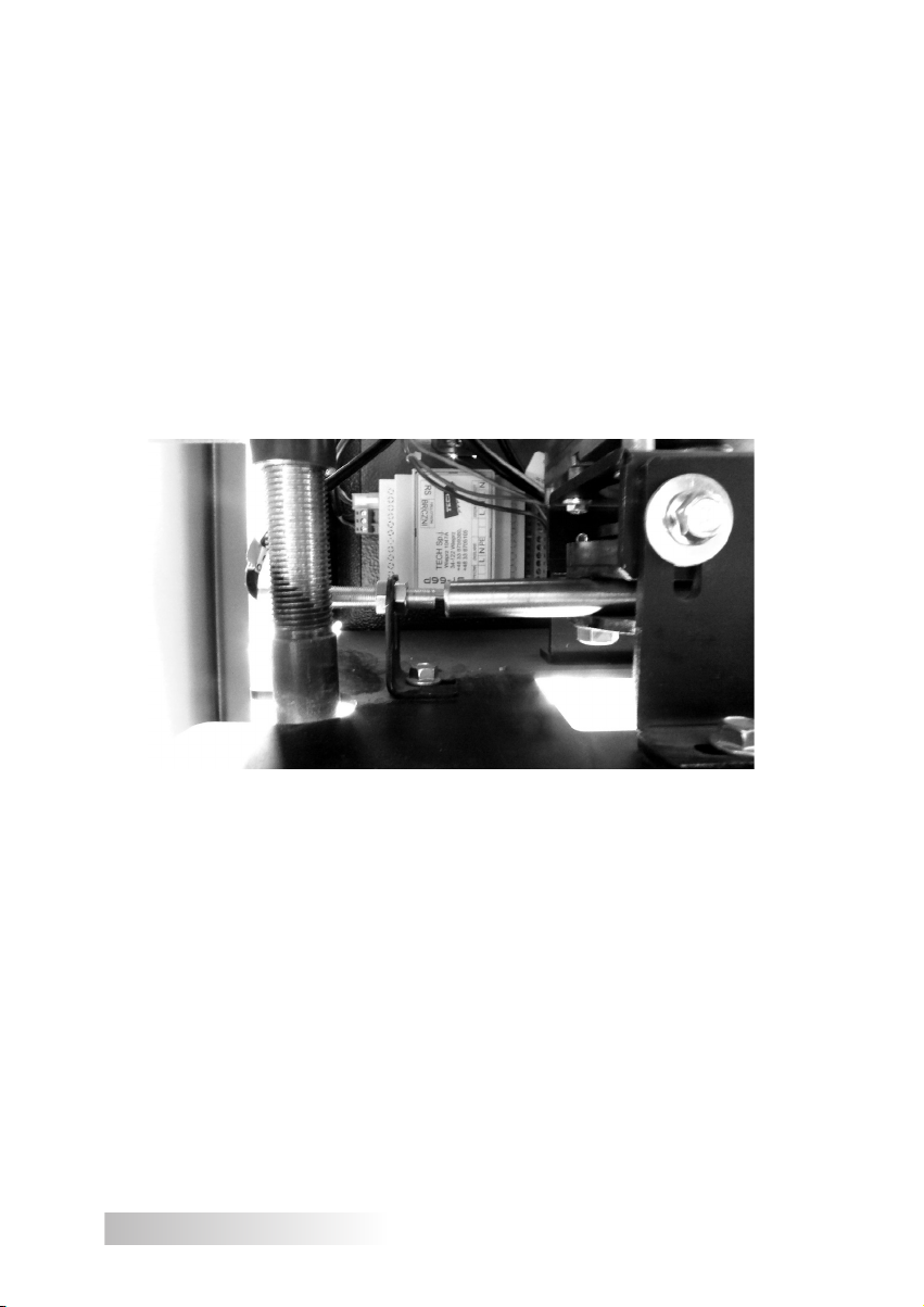
Figure 2 Location of a temperature sensor with
a capillary tube– thermal protection sensor
The fuel hopper (tank), together with the feeder drive mechanism and the
blower fan, is installed in the back part of the boiler, behind its body.
Adjustment feet with the adjustment range of 30 mm ensure the boiler final
alignment versus the floor. The user is responsible for possible installation of adjustment feet, according to guidelines provided in this instruction (Fig. 8).
A characteristic feature of SAS AGRO-ECO boilers is an automated high-performance self-cleaning furnace burning precisely the amount of fuel necessary
to
obtain the temperature set on a controller by the user. Furnace components
exposed to high temperatures are made of stainless steel and ceramic materials. Ceramic panels used in the furnace ensure optimum conditions for
biomass burning (an optimum temperature for oats burning is 1200 °C) and
increase fur-nace effectiveness, while they have a positive effect on its life.
Fuel from a tank is fed automatically with a screw conveyor (a system with two
screws and a transfer duct).
The funnel-shaped fuel tank ensures gravitational fuel transport through a loading opening from a fuel tank to an upper fuel feeding pipe with a screw installed,
then fuel is transported gravitationally through a transfer duct to a lower distribution pipe in which the second screw is installed. With this screw fuel is supplied
to the furnace chamber. The screws are rotated by gear wheels driven by a chain
driven by a gearmotor. Safe fuel transport between the upper screw, the bottom
screw and the furnace chamber is only possible due to correctly selected number
of teeth in transmission wheels. All processes leading to burning of supplied fuel
in air supplied with the blower fan installed under fuel tank casing take place on a
9
Page 10
grate in the furnace chamber. The supplied air is separated in the air chamber. The
initial air is supplied under the grate, while the secondary air is pumped through
a system of nozzles in ceramic panels into the fuel burning zone. The appropriate
– depending on a type of burned fuel – stream of air supplied by the blower fan is
controlled with a manual knob located on the boiler side wall.
The furnace grate is divided into a fixed part and a section of moving fire bars.
The cyclically activated moving grates driven by an eccentric mechanism remove
fuel burning residues, i.e., ash, particularly in form of sintered slag, from the furnace space to the boiler chamber. This solution maintains the furnace space of
the burner in a "clean" condition without interrupting the continuity of the burning
process. After a clean out cycle the moving grates are placed in slots of the lower
part of the furnace. The grate is positioned with a position control sensor (Hall
effect sensor, see Fig. 3, Fig. 6 and Fig. 7).
Figure 3 Moving grate positioning sensor (Hall effect sensor ).
NOTE:
Correct operation of the moving grate mechanism requires a correct setting of
the Hall effect sensor. A distance between the position sensor and the wrapping
connector of the moving grate should be 3 to 5 mm, these components should be
aligned axially.
The fuel feeder design developed at ZMK SAS, using a set of two screws,
is protected by an application No. W.120870 issued by the Polish Patent Office.
Additionally, for easier operation the boiler is equipped with a ceramic heater,
firing fuel during the boiler start-up (fuel self-firing). An automatic fuel firing and a
system to maintain flame after the set temperature is reached ensures an efficient
operation of this boiler even during periods of low demand for heat (an option
for continuous operation or operation with a domestic hot water tank during the
summer).
10
Page 11
A microprocessor controller automatically controls operation of the fuel feeder,
the blower fan, the fuel igniting heater and the furnace cleaning mechanism.
During the final phase of biomass burning, a residual negligible non-flammable
part of fuel – ash – is transferred to the ash box chamber equipped with a removable ash drawer that should be emptied periodically (ash resulting from biomass
burning can be used as valuable ecological fertiliser for soil enrichment).
An efficiently working boiler furnace burns the amount of fuel necessary to
maintain the temperature set on the controller by the user. Thus, the controller
continuously measures a temperature of water in the boiler, and on this basis appropriately controls operation of the boiler operational components. At the same
time the controller controls operation of pumps: central heating, domestic hot water, floor, and circulatory (when the heating system is equipped with pumps). In a
system equipped with a mixing valve with a cylinder, the mixer can be controlled
directly from the boiler controlled. Connection points for circulatory pumps, temperature sensors and the mixer are located on the boiler side wall (see Fig. 4, Fig.6
and Fig. 7).
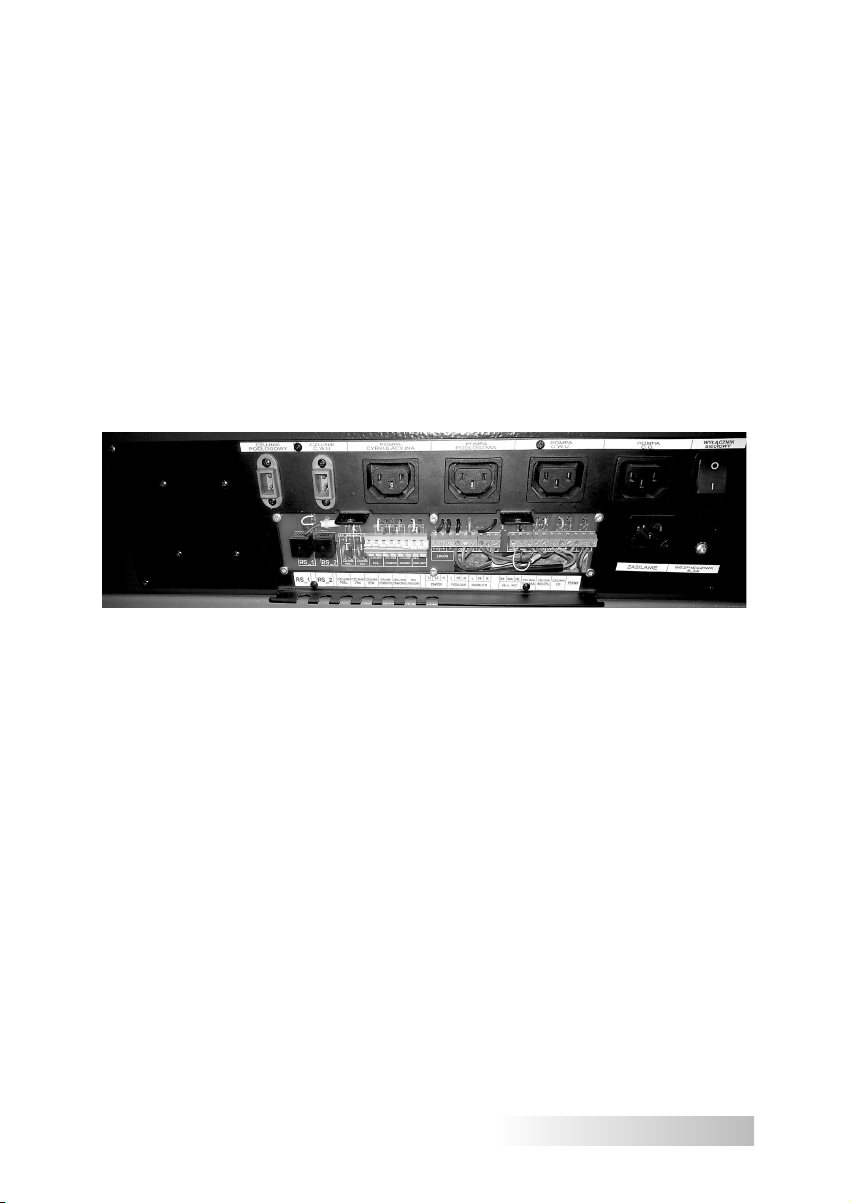
Figure 4 Connection terminal strip supplying control equipment
(note: the photograph shows an example of connection layout, details are provided in the controller operation and
maintenance manual).
The module (see Fig. 4, Fig.6 and Fig. 7) controlling furnace operation is located under the insulation upper lid. The module controls the fuel igniting heater
and the mechanism for furnace cleaning together with the positioning sensor (Hall
effect sensor). The temperature controller installed on the boiler controls operation
of the blower fan, the fuel feeding mechanism, and the feeder temperature sensor.
Cooperation between the module (Fig.6 and Fig. 7 item 32) controlling the burner
and the main boiler controller (Fig.6 and Fig. 7 item 14) is possible due to RSbased wired communication.
11
Page 12
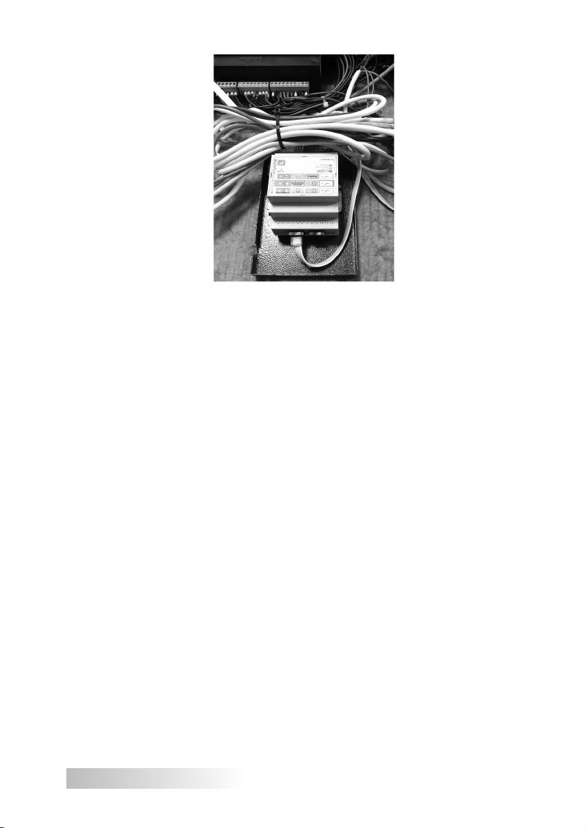
Figure 5 Module controlling burner operation.
The boiler controller* is also adapted to operation with a room temperature
controller.
Advantages of the boiler include its simple operation in form of periodic supplementing of fuel in the tank (hopper: every 1 to 3 days, depending on weather
conditions and building insulation) and removing of ash from the ash drawer without a need to put the boiler off. After firing the boiler does not require continuous
operation, and apart from periodic planned maintenance, it can be used in general
throughout the heating season. The boiler can also be used outside the heating
season in a system with a domestic hot water tank.
A boiler room with a solid fuel boiler is not maintenance-free and requires
periodic monitoring. During boiler operation certain daily activities must be
performed (e.g., verification of the furnace operation), to prevent emergency
situations.
Generally, the SAS AGRO-ECO boiler is operated automatically (in a continuous mode) using a unit consisting of the gearmotor-driven fuel feeder, the
self-cleaning blower furnace, and the digital temperature controller.
Additionally, the boiler is adapted to operation in the "emergency burning"
mode, e.g., in the event of power outage or failure of the feeder/fan (see details
in chapter 8.2.2). Then the boiler runs using a natural flue gas flow, therefore, the
boiler operation in this mode does not require any power supply. In this mode a
temperature of water in the boiler can be checked with an analogue thermometer.
The burning process can then be controlled manually with a screw adjusting air
supply in an air-dosing flap. The boiler is equipped with a bracket for installation of
* Detailed description of the controller design, work and operation is provided in the con-
troller operating manual attached to this documentation.
12
Page 13

an emergency steel grate. This grate is not a standard boiler equipment.
It is forbidden to burn plastic materials; this may result in blocking of air
distribution openings and contamination of the furnace plate. Contamination
of the heat exchanger surface leads to reduced boiler efficiency and deterioration in the burning process. It is forbidden to use flammable materials
(such as petrol, kerosene, or solvents) for boiler firing, as this may result in
a fire or explosion.
To ensure safe operation, the SAS AGRO-ECO boiler is equipped with a security system consisting of several steps. The protective devices include protection
against flashback into the fuel tank through the fuel feeder (a temperature sensor
in the fuel route), a set of two screws separated with a transfer duct, and a thermal
switch protecting against boiler overheating.
The feeder in the SAS AGRO-ECO boiler, equipped with two transport screws,
consists of two fuel distribution pipes separated with the transfer duct ensuring a
distance between them. Feeders previously available in the market particularly for
biomass, were equipped with a single screw mechanism. This system requires an
additional protective device to be installed, securing against uncontrolled flashback to the fuel tank. For this purpose, an extinguishing system based on a thermally activated valve and an external water tank is used. When temperature in the
fuel supply system rises, the valve is opened and water is poured over the furnace.
After this procedure the boiler furnace and chamber must be thoroughly cleaned,
and those operations are very labour- and time-consuming. This mechanism protects against uncontrolled flashback into the fuel tank in boilers, without a need
to install the extinguishing system. The feeder in the SAS AGRO-ECO boiler was
designed to eliminate a risk of flashback from the furnace chamber to the fuel tank
during the normal operation or the fuel feeder downtime, as well as during power
supply outages (no power supply).
The system monitoring the boiler operating equipment guarantees the boiler
is automatically switched off in the event of the fuel feeder blocking, failure of the
system driving the moving grates, flame extinguishing in the heating chamber, etc.
In the event of power outage the operational status and all controller settings are
remembered, therefore, when the power supply is restored, the boiler is started
automatically, bringing the system to the required temperature.
13
Page 14

4. SAS AGRO-ECO BOILER EQUIPMENT
SAS AGRO-ECO, the automatic boiler with a control system and a self-clean-
ing furnace is delivered in an assembled state, equipped with a controller, a fan, a
fuel feeder with a gearmotor, a fuel lighter, ceramic panels, a fuel tank, an automated furnace, and ash-box, feeding-firing, and clean out doors, with thermal insulation of mineral wool, and outer insulation in form of a jacket of powder-coated steel
sheets of high resistance to corrosion. The SAS AGRO-ECO boiler is equipped
with fuel feeder (a system of two transport screws separated with a transfer duct),
and a fuel tank, with a hopper on the left (L) or the right (R) of the boiler (always
in the back). The hopper location should be clearly stated, as it is not possible to
move it to the other side afterwards. The user is responsible for possible installation of adjustment feet, according to guidelines provided in this instruction.
The digital equipment (control systems) for the SAS AGRO-ECO boiler as
specified in the attached operating manual for the temperature controller.
14
Page 15
Table 1 SAS AGRO-ECO boiler equipment
Boiler standard equipment
Boiler operating and maintenance documentation
1
(operating manual + warranty card)
2 Operating manual + warranty card for a temperature regulator (controller) pieces 1
3 Warranty card for a blower fan pieces 1
Temperature regulator (controller operating a mixing valve*,
Ethernet module**) together with a module controlling the burner operation
4
and a set of cables and sensors for the system operation (details in the
controller operation and maintenance manual)
5 Blower fan pieces 1
6 Analogue thermometer pieces 1
7 Fuel feeder with a gearmotor pieces 1
8 Drive motor for moving grates pieces 1
9 Grate position sensor – Hall effect sensor pieces 1
10 Stainless steel biomass furnace with a set of moving grates set 1
11 Feeder temperature sensor pieces 1
12 Flue gas temperature sensor pieces 1
13 Ceramic panels (top/side) set 1
14 Fuel lighter pieces 1
15 Fuel tank pieces 1
16 Moving parts guard (fuel tank casing) set 1
17 Pressure relief valve (2.5 bar) pieces 1
Tool kit for boiler operation
18
(poker, cleaning rod, scraper, ash shovel)
19 Adjustment feet for boiler levelling
20 Connector (G½”) for the temperature overheating sensor *) pieces 1
(excluding boilers above 36 kW) pieces 4
pieces 1
pieces 1
set 1
Boiler optional equipment
1 Room regulator pieces 1
2 Module controlling an additional mixing valve **) pieces 1
3 Draught regulator (G¾”) with a measuring capillary tube, L=140mm pieces 1
4 GSM module **) pieces 1
5 Ethernet module **) pieces 1
6 Module for heat buffer tank control ** pieces 1
Thermostat valve with a capillary tube (G½”)
- open vented system with a plate exchanger (e.g. Regulus, type BVTS)
7
- sealed system (e.g. SYR 5067)
8 Steel grating for "emergency burning" pieces 1
Module controlling an external fuel hopper together with a set of fuel
9
level sensors **)
protecting against overheating *)
pieces 1
set 1
* controlling two mixers – Recalart MultiFun controller
** concerns boilers with a Recalart MultiFun controller
*) excluding boilers above 100 kW
**) concerns boilers with a TECH ST-450zPID controller
15
Page 16
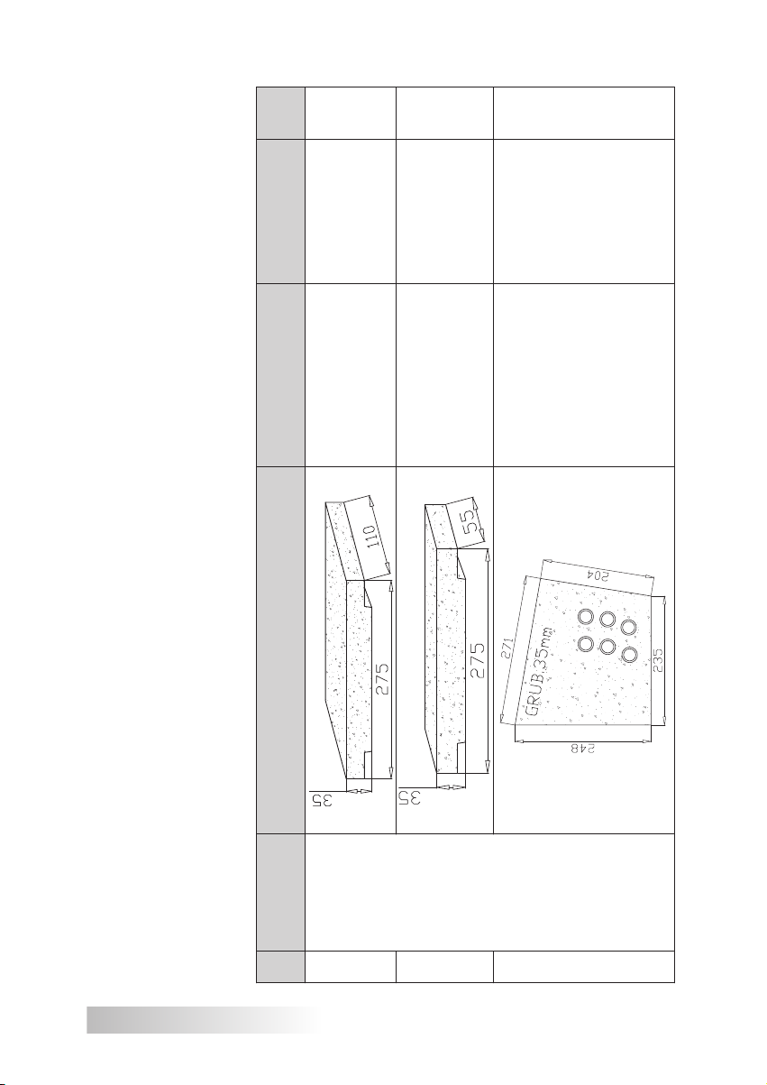
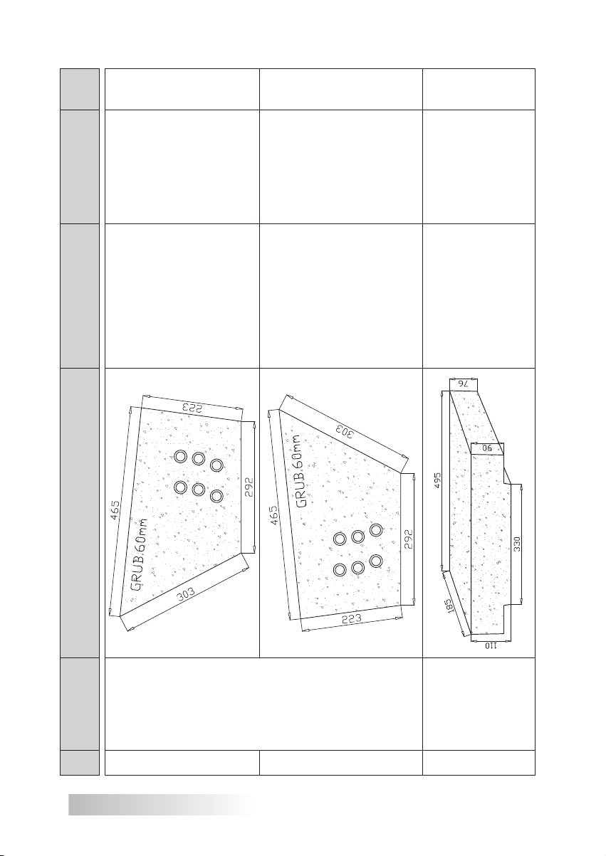
The automated boiler SAS AGRO-ECO is equipped with a set of ceramic panels (refractory concrete). Biofuel water content
significantly affects combustion process and achieving a full boiler heating effect. The automated furnace equipped with
ceramic panels ensures optimum conditions for biomass burning, increases burning process effectiveness, and has a
positive effect on the boiler's life.
Ceramic panels are wearable material, subject to regular replacement The order should be placed according to the
product code, as listed below.
(set)
Pcs
1
1
1
-17_23-G
CER-ECO_AGRO
for boilers ECO,
AGRO-ECO 17,23 kW
Upper ceramic panels
-17_23-GM
CER-AGRO
panels for a boiler
Upper small ceramic
AGRO-ECO 17,23 kW
CER- AGRO-
17_23_29_36-BL
AGRO-ECO
for the boiler
17, 23, 29, 36 kW
Left side ceramic panels
SAS
17/23kW
AGRO-ECO
No. Boiler Ceramic panels (dimensions) Name Product code
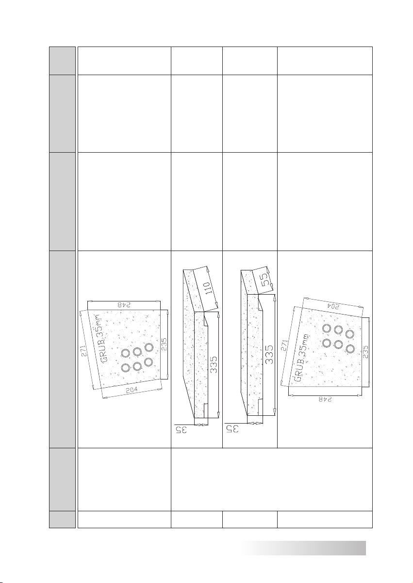
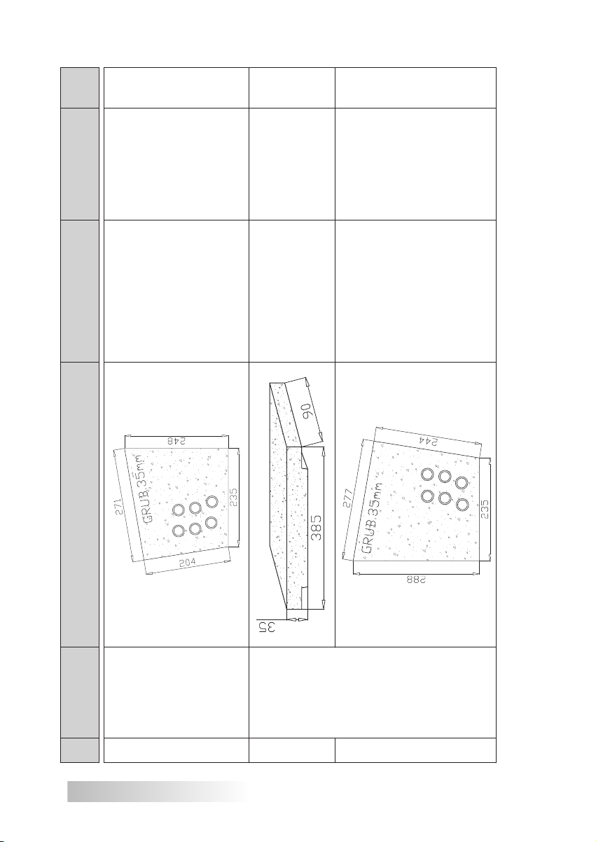
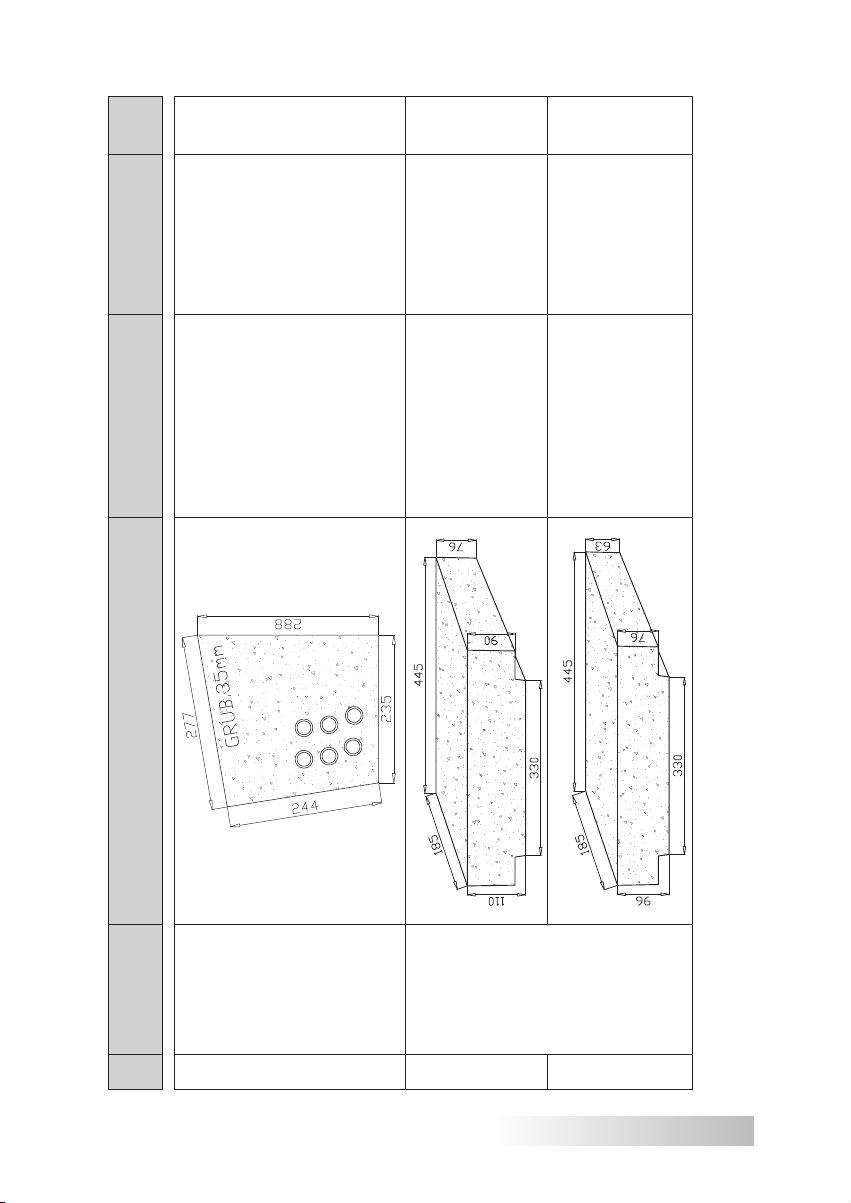
Table 2 Spare parts catalogue – ceramic panels
16
1a
1b
1c
Page 17
(set)
Pcs
1
1
1
1
CER- AGRO-
17_23_29_36-BP
AGRO-ECO
Right side ceramic
17, 23, 29, 36 kW
panels for the boiler
-29_36-G
CER-ECO_AGRO
Upper ceramic panels
for boilers ECO 29 kW,
AGRO-ECO 29, 36 kW
-29_36-GM
CER-AGRO
ECO 29 kW,
panels for boilers
Upper small ceramic
CER- AGRO-
17_23_29_36-BL
17, 23, 29, 36kW
AGRO-ECO 29, 36 kW
Left side ceramic panels
for the boiler AGRO-ECO
No. Boiler Ceramic panels (dimensions) Name Product code
SAS
AGRO-ECO
1d
17/23kW
2a
2b
SAS
AGRO-ECO
29/36kW
2c
17
Page 18
(set)
Pcs
1
2
1
CER- AGRO-
17_23_29_36-BP
AGRO-ECO
Right side ceramic
17, 23, 29, 36 kW
panels for the boiler
-42_48-G
CER-AGRO
for a boiler
Upper ceramic panels
AGRO-ECO 42, 48 kW
-42_48-BL
CER- AGRO
for the boiler
AGRO-ECO 42, 48 kW
Left side ceramic panels
No. Boiler Ceramic panels (dimensions) Name Product code
18
SAS
AGRO-ECO
2d
29/36kW
3a
SAS
AGRO-ECO
42/48kW
3b
Page 19
(set)
Pcs
1
1
1
-42_48-BP
CER- AGRO
42, 48 kW
AGRO-ECO
Right side ceramic
panels for the boiler
-58_68-GD
CER-AGRO
panels for boilers
Upper large ceramic
AGRO-ECO 58, 68 kW
Upper small ceramic
-58_68-GM
CER- AGRO
panels for boilers
AGRO-ECO 58, 68 kW
L P. Boiler Ceramic panels (dimensions) Name Product code
SAS
AGRO-ECO
3c
42/48kW
4a
SAS
AGRO-ECO
58/68kW
4b
19
Page 20
(set)
Pcs
1
1
1
-58_68-BL
CER-AGRO
58, 68 kW
Left side ceramic panels
for the boiler AGRO-ECO
-58_68-BL
CER-AGRO
AGRO-ECO
Right side ceramic
panels for the boiler
CER-AGRO
-78_100-GD
AGRO-ECO
78, 90, 100 kW
panels for boilers
Upper large ceramic
No. Boiler Ceramic panels (dimensions) Name Product code
20
4c
SAS
AGRO-ECO
58/68kW
4d
SAS
AGRO-ECO
78/90/100 kW
5a
Page 21

(set)
Pcs
1
1
1
CER-AGRO
-78_100-GM
AGRO-ECO
78, 90, 100kW
panels for boilers
Upper small ceramic
-78_100-BL
CER-AGRO
AGRO-ECO
Left side ceramic
78,90,100kW
panels for the boiler
-78_100-BP
CER-AGRO
AGRO-ECO
Right side ceramic
78, 90, 100 kW
panels for the boiler
No. Boiler Ceramic panels (dimensions) Name Product code
5b
SAS
AGRO-ECO
5c
78/90/100 kW
5d
21
Page 22

(set)
Pcs
3
1
1
-150-G
CER-AGRO
Upper ceramic
panels for boilers
AGRO-ECO 150 kW
-150-BL
CER- AGRO
Left side ceramic
panels for the boiler
AGRO-ECO 150 kW
-150-BP
CER- AGRO
Right side ceramic
panels for the boiler
AGRO-ECO 150 kW
No. Boiler Ceramic panels (dimensions) Name Product code
22
6a
SAS
6b
150 kW
AGRO-ECO
6c
Page 23

5. TECHNICAL AND OPERATIONAL PARAMETERS
Basic output parameters together with technical and operational parameters for
SAS AGRO-ECO boilers are listed in Tab. 3, Tab. 4, and Fig. 6 and Fig 7.
6. FUEL
A trouble-free operation of a SAS AGRO-ECO boiler with an automated burner
and a fuel feeder depends on use of appropriate fuel or adapting a boiler operation
mode to available fuel.
Correct biomass selection not only guarantees economic fuel consumption
(effective fuel
of biofuel and, to a large extent, its water content, is also of importance for achieving a boiler heating effect.
SAS AGRO-ECO boilers burn various types of fuel, including agricultural products, and this offers extensive possibilities to the user.
A basic fuel to be used in the automatic mode in the SAS AGRO-ECO heating
boilers is biomass in form of pressed wood granulate, or pellets, according to
EN 14961-2. Do not use fuel of granulation coarser than specified*, as such fuel
may hinder the feeder operation and damage it. The SAS AGRO-ECO boiler
equipped with the automated feeder is not intended to be used with fossil fuels. Various grain (oats, rye, barley, wheat) or dry fruit stones (e.g., sweet cherry
or cherry, etc.) of parameters conforming to EN 14961-6 can be used as an
alternative (substitute) fuel, burning with similar effectiveness. Grain of poor quality, affected by diseases or obtained from crops grown on contaminated grounds,
can be used as fuel.
For correct burning of alternative fuel settings correct for a relevant type of fuel
must be entered into the boiler controller.
burning), but also reduces time required for boiler operation. A type
* In particular, during fuel loading or replenishment attention should be paid to undesira-
ble objects or stones that may block feeder mechanism.
23
Page 24

Table 3 TECHNICAL AND OPERATIONAL PARAMETERS
SAS AGRO-ECO 17-48 kW BOILER
230
~150–165
to 310
230
~150–165
(+600onring)
Ø280
25x25
205
~130–145
205
~130–145
170
1.5 2.0 2.5 3.0 3.5 4.0
~110–120
170
upto250(+600onring)
~110–120
Thermalefciency % 87.7–88.8
3.
2. Heating surface m
3
kg
dm
6. Boiler water holding capacity l 90 100 120 140 160 190
4. Fuel consumption * kg/h 1.9 2.6 3.3 4.1 4.8 5.5
5. Fuel tank capacity
°C 90–210
°C 85
7. Boiler weight (without water) kg 520 550 580 640 720 740
8. Required hot gas pass mbar 0.30
9. Flue gas temperature
10. Max. accept. operational pressure bar 1.5
11. Max. accept. oper. temp.
°C 60–80
°C 55
Amps mm 1550 1650 1650 1730 1730 1800
A1 mm 840 940 940 1020 1020 1090
B mm 550 550 620 620 670 670
B1 mm 450 450 520 520 570 570
H **) mm 1650 1650 1690 1690 1740 1740
H1 **) mm 1420 1420 1420 1440 1520 1540
C mm 260 360 360 430 430 450
Basic boiler dimensions
12. Recomm. operat. temp. of heating water
14. Power supply V/Hz ~230 / 50
15. Power consumption *** W
13. Min. temp of return water **
16.
C1 mm 180 180 180 180 180 250
D : mm 520 520 520 520 620 620
Furnace chamber dimension *)
17. Flue diameter mm Ø 160 Ø 180 Ø 200 Ø 200 Ø 220 Ø 220
18. Connector thread (supply/return) " G 1¼ G 1½ G 2
2
1. Nominal boiler output kW 17 23 29 36 42 48
No. Parameter Unit SAS AGRO-ECO
* for operation at a moderate load (50% of boiler nominal output) for basic fuel.
** whenrecommendationsconcerningmaintainingofaspeciedrangeofheatingwatertemperaturesarenotfollowed,
the boiler must be obligatorily connected to the heating system equipped with a three- or four-way valve protecting
against so-called "low-temperature corrosion"
*** temporary power consumption depends on the equipment operating mode
*) concerns burning on an emergency furnace
**) when adjustment feet are used (excluding boilers of output exceeding 36kW), the dimension increases from min. 29
mm to max. 56 mm
19. Pressure relief valve (2.5 bar) " G ½
20. Min. stack height m 6 7 8 9
22x22
21x21
20x20
18x18
cm x cm
Min.uepipediameter
21.
Ø250
Ø240
Ø220
Ø210
mm
24
Page 25

Table 4 TECHNICAL AND OPERATIONAL PARAMETERS
SAS AGRO-ECO 58-150 kW BOILER
5.0 6.0 7.0 8.0 9.0 14.0
2
890
~580–630
510
~330–360
425
~275–300
425
~275–300
300
~195–210
285
~185–200
3
kg
dm
°C 90–210
Ø400
to 625
(+600onring)
32x32
Ø380
29x29
Ø360
28x28
orangedconnection G 3 orangedconnection
upto325(+600onring)
Ø320
26x26
°C 85
°C 60–80
°C 55
Amps mm 1920 1990 2090 2190 2240 2560
A1 mm 1160 1180 1180 1280 1280 1550
B mm 740 740 780 780 780 880
B1 mm 640 640 680 680 680 780
H mm 1890 1920 1990 1990 2100 2220
C mm 500 500 500 590 590 770
H1 mm 1570+c* 1610+c* 1610+c* 1610+c* 1830+c* 1970+c*
C1 mm 250 250 250 280 280 370
D : mm 620 650 650 650 650 750
mm
cm x cm
Furnace chamber
Thermalefciency % 87.7–88.8
9. Flue gas temperature
8. Required hot gas pass mbar 0.45 0.55
7. Boiler weight (without water) kg 890 1020 1260 1350 1420 2000
6. Boiler water holding capacity l 260 350 420 510 620 930
5. Fuel tank capacity
3.
2. Heating surface m
4. Fuel consumption * kg/h 6.6 7.2 8.3 9.6 10.7 15.2
1. Nominal boiler output kW 58 68 78 90 100 150
No. Parameter Unit SAS AGRO-ECO
* for operation at a moderate load (50% of boiler nominal output) for basic fuel.
** when recommendations concerning maintaining of a specified range of heating water temperatures are not followed,
the boiler must be obligatorily connected to the heating system equipped with a three- or four-way valve protecting
against so-called "low-temperature corrosion"
*** temporary power consumption depends on the equipment operating mode
*) concerns burning on an emergency furnace
c* bracket used for loading, of 150 mm
12. Recomm. operat. temp. of heating water
13. Min. temp of return water **
14. Power supply V/Hz ~230 / 50
10. Max. accept. operational pressure bar 1.5
11. Max. accept. oper. temp.
15. Power consumption *** W
Basic boiler
dimensions
16.
dimension *)
18. Connector thread (supply/return) „ G 2 G 2½
17. Flue diameter mm Ø 250 Ø 260 Ø 270 Ø 280 Ø 300 Ø 360
19. Pressure relief valve (2.5 bar) „ G ½ G ¾ G 1
20. Min. stack height m 10 11 12 15
Min.uepipediameter
21.
25
Page 26

Figure 6. CONSTRUCTION DIAGRAM OF A SAS AGRO-ECO
BOILER
(concerns boilers of up to 17–48 kW)
13. Pressure relief valve
14. Temperature regulator (controller)
15. Hot water connector
16. Analogue thermometer
sor with a capillary tube **
17. Connector for a temperature sen-
7. Front clean out door
8. Draught regulator *
9. Connection terminal strip
10. Flue
11. Flue gas temperature sensor
1. Air-dosing flap
2. Ash-box door
3. Ash drawer
4. Boiler casing (body)
* draught regulator is not included in the boiler standard equipment.
** excluding boilers above 100kW. Thermal protection against overheating (a thermostat valve, e.g., Regulus BVTS for
an open vented system with a plate exchanger or SYR 5067 for a sealed system) is not included in the boiler standard
equipment.
*** The emergency grate is not a standard boiler equipment.
**) when adjustment feet are used (excluding boilers of output exceeding 36 kW), the dimension increases from min. 29
mm to max. 56 mm.
***) SAS AGRO-ECO 17-48kW is equipped with a controller installed in the mounting box
5. Thermal insulation
26
12. Fuel tank (hopper)
6. Firing/feed door
Page 27

Figure 7. CONSTRUCTION DIAGRAM OF A SAS AGRO-ECO
BOILER
emergency grate***
tion (lighter, moving grates)
29. Ceramic panels
30. Bracket for installation of an
31. Adjustment feet **)
32. Module controlling burner opera-
(concerns boilers of up to 58-150 kW)
23. Pressure equalising system
24. Hall effect sensor
25. Grate drive mechanism
26. Feeder temperature sensor
27. Blower fan
28. Heater (electrical lighter)
screw)
18. Side clean out hatch
19. Return water connector
20. Discharge connector
21. Gearmotor with a feeder (double
22. Guard for moving parts
27
Page 28

NOTE! Use of fuels other than recommended by the manufacturer
may damage the feeder resulting in a loss of a warranty for a given
feeder.
It is forbidden to burn plastic materials; this may result in damage to the
furnace. Contamination of the heat exchanger surface leads to reduced
boiler efficiency and deterioration in the burning process. It is forbidden to
use flammable materials (such as petrol, kerosene, or solvents) for boiler
firing, as this may result in a fire or explosion.
The density determines fuel durability, wear and formation of pulp;
therefore, too low density may result in blocking of the feeder mechanism.
It is forbidden to use fuel of moisture content exceeding that specified in the table. Fuel with high water content may hinder correct burning
process and result in damage to the screw, the feeder or the fuel tank
(premature corrosion).
Additionally, providing the furnace with an ash-removal system based
on moving fire bars allows use of fuels with a tendency to form slag.
Correct biomass selection not only guarantees economic fuel consumption (effective burning), but also reduces time required for boiler operation. Use of the recommended fuel type and grade ensures correct and
failure-free operation of the feeder and the boiler, economic fuel consumption versus pellet of poor quality, as well as reduces emissions of harmful
compounds during the burning process.
Fuel of poor quality parameters (high water content, low calorific value,
presence of stones, etc.) may cause problems with selection of settings
for optimum boiler operation, leading to formation of sinter on the furnace
and high fuel losses with ash.
NOTE: The fuel tank should be loaded with fuel free of water and
excessive quantities of fine fractions or foreign bodies! High water
content and contaminations delivered to the feeder with the fuel have
a negative effect on the hopper life!
Use fuels recommended by the manufacturer (possibly certified)!
A fuel storage place should be secured against weather conditions.
For this purpose, a roofed, dry and ventilated place must be prepared.
The fuel storage surface should be sufficient for fuel storage for the whole
heating season.
28
Page 29

Table 5 Basic parameters of pellets for SAS AGRO-ECO boilers:
No. Parameter Unit Scope
1 Diameter mm 6–8
2 Length mm 5–35
3 Bulk density kg/m³ ≥ 600
4 Calorific value MJ/kg 16.5–19
5 Abrasion resistance % ≤ 2.5
6 Ash content % ≤ 0.5
7 Sulphur content % ≤ 0.03
8 Nitrogen content % ≤ 0.3
9 Chlorine content % ≤ 0.02
10 Water content % ≤ 12
Boiler operation in the "emergency burning" mode
Also long-flame fuels, such as wood (e.g. hornbeam, oak, ash, or
beech, etc.) can be effectively burned on the steel grates of the "emergency furnace". The wood should be seasoned for at least one year! Using
wet wood reduces performance and has an adverse effect on the boiler
life, causing its corrosion.
Then the boiler runs using a natural flue gas flow, therefore, the boiler operation in this mode does not require any power supply. The burning process can then be controlled manually, using an air supply control
screw in the air-dosing flap or the draught regulator (the draught regulator
is not included as a standard boiler accessory, however, it can be installed
on a connector in the upper part of the boiler). When it is not installed, the
connector must be secured with a plug. The draught regulator connected
to the flap with a cable automatically -mechanically – doses air supply
to the burning process. Then a temperature of water in the boiler can be
read on a thermometer. This solution not only ensures the boiler operation in emergency situations resulting, e.g., from power outage, but also
provides an opportunity for periodic burning of other fuels or for shortterm cycles of "warming up" before, during or after the end of the heating
season.
NOTE:
For correct control of the burning process in the "emergency burning"
mode, the draught regulator should be equipped with a measuring capillary tube 140 mm long.
The steel grate is not a standard boiler equipment.
29
Page 30

7. BOILER INSTALLATION GUIDELINES
The boiler must be installed by qualified personnel holding relevant licenc-
es (a professional, appropriately trained and holding required licences to perform
maintenance and repair works). An installer is obliged to become thoroughly acquainted with the product and its function, and an operating mode of its protective
systems. They should provide necessary minimum information on the boiler startup and daily operation to its final user.
Before starting to connect the boiler to a heating system, you must read
and understand this operation and maintenance manual.
7.1. BOILER ROOM REQUIREMENTS
The boiler room in which the central heating boiler is installed must meet current specific regulations in force in a country of destination (e.g. PN-87/B-02411
Heating. Built in boiler house for solid fuel. Requirements).
boilers are located possibly centrally to heated rooms, and the boiler
should be placed as closely as possible to a chimney;
an entrance door should open to the outside of the room and must be
constructed of non-flammable materials, a floor in the boiler room should
be made of non-flammable materials or coated with 0.7 mm steel sheet to
a distance of at least 0.5 m from the boiler edge.
the boiler room of heat capacity up to 25 kW should be equipped with sup-
ply ventilation in form of a nonclosing aperture of at least 200 cm
the boiler room of heat capacity above 25 kW should be equipped with a
supply duct of cross-section no less than 50% of a chimney cross-section
area, however, no less than 20x20 cm with an outlet at a height up to 1 m
above the floor level in the back part of the room; a device controlling air
flow should be installed in a supply aperture or duct, however, it should not
reduce the cross-section to less than 1/5 (no supply ventilation or its obstruction may result in such events as smoke formation or inability to reach
higher temperature);
the boiler room of heat capacity up to 25 kW should be equipped with ex-
haust ventilation (a duct of non-flammable material) under a room ceiling
of a cross-section no less than 14x14 cm
the boiler room of heat capacity above 25 kW should be equipped with an
exhaust duct of cross-section no less than 50% of a chimney cross-section
area, however, no less than 14x14 cm (the exhaust ventilation removes
harmful gases from the room);
the exhaust duct should be routed above a roof level and located close to
the chimney. No closing devices should be installed on the exhaust duct.
2
area;
30
Page 31

NOTE:
Use of mechanical ventilation is unacceptable.
The boiler room should be provided with natural and artificial lighting.
FOR SAFETY REASONS IT IS RECOMMENDED TO EQUIP THE BOILER
ROOM WITH A CARBON OXIDE (CO) AND A SMOKE SENSORS.
7.2. NOISE AND NOISE REDUCTION METHODS
The manufacturer made all efforts possible to maintain a noise emitted by
the heating device at a safe acceptable level of <65dB(A). Sub-assemblies (fan,
fuel feeder, moving grate mechanism) installed in the boiler are characterised by
their low noise index. Air-supply ducts were designed in a way preventing excessive noise during air flow. As there are no technical options to monitor the
condition of wearable boiler components and detect undesirable objects in the
boiler and its sub-assemblies, the boiler operation manual contains information
on troubleshooting (as well as on technical and maintenance assistance). Wearable (deformed in operation) components of the boiler, fuel feeder, moving grates
and blower fan may emit excessive noise; therefore, regular technical and maintenance inspections are recommended. Due to the solid fuel boiler design and its
moving components, it should be installed in a separate room (see chapter 7.1
"Requirements for a boiler room"). To minimise noise transmission from the heating device onto other parts of the system, damping connectors (vibration compensator, e.g., EFAR, DANFOSS) can be installed. The boiler should be set according
to guidelines provided in chapter 7.3 "Setting a boiler".
7.3. SETTING A BOILER
The boiler should be set in a way ensuring safe and easy operation of the
furnace and the ash box, as well as fuel loading and boiler cleaning. In particular, an access to clean out hatches and the flue pipe must be ensured, for
periodic removal of the burning process residues.
A distance between the boiler and the boiler room walls and flammable
materials should be no less than 1 m.
No special foundations are required for the boiler; however, a load bearing capacity of the floor on which the boiler is installed should consider the total weight
of the boiler with water and fuel. It is recommended to set the boiler on a concrete
platform 5 cm above the floor level, edged with steel angle sections. The boiler
should be set in a way ensuring safe and easy operation of the furnace and the
ash box, as well as fuel loading and boiler cleaning.
A distance should be ensured between the boiler back side and the walls of no
less than 0.7 m, the boiler side and the walls of no less than 1.0 m, and the boiler
front and the opposite wall of no less than 2.0 m.
31
Page 32

When the floor is not levelled precisely, adjustment feet can be installed for
final alignment of the boiler versus the floor. The SAS AGRO-ECO boiler is provided with 4 adjustment feet with a set of nuts and washers. The adjustment feet are
not provided for boilers above 36 kW. The adjustment feet installation is shown in
Figure 8.
A) Installation of the adjustment feet
1 – threaded adjustment foot
(regulation scope 30 mm)
2 – nut M12
3 – washer Ø13
4 – installation opening Ø13 mm
5 –side skid of the boiler
B) Boiler with feet installed
Figure 8. Installation of adjustment feet in a SAS AGRO-ECO boiler
The boiler alignment versus the floor is adjusted with a wrench No. 19 and a
bottom setting nut (item 2). When the boiler position versus the floor is finally set,
install the upper nut (item 3) and block the whole set by screwing on the upper
blocking nut (item 2). The wrench No. 19 is not provided with the boiler. The SAS
AGRO-ECO boiler with the adjustment feet installed is shown in Fig. 8 B).
32
Page 33

7.4. BOILER STACK CONNECTION
The design of a flue pipe and its connection to the boiler should conform to the
requirements of current national regulations in a country of destination (e.g., Minister of Infrastructure Regulation concerning technical conditions that should be met
by buildings and their setting, of 12 April 2002, Journal of Laws No. 75, item 690).
The boiler should be directly connected to the stack with a smoke connection
in form of a steel pipe (of a thermal resistance of >400 °C) of a diameter allowing
its tight connection to the flue outlet and insertion into the flue pipe. A connection
between the flue and the stack must be tightly sealed (e.g., with high temperature silicone, ceramic sealant, etc.). The pipe should slope up slightly towards the
stack (at least 5°).
Dimensioning and selection of the flue pipe and the connector should be
performed by a designer holding necessary licences, and the stack system
should be constructed by a qualified person in accordance with current specific regulations in a country of destination.
The stack height and cross-section, as well as the precision of its dimensioning
have a significant effect on a correct boiler operation, therefore they should ensure
maintaining of the required size of the flue pipe (see Table 3, Table 4). A too small
pipe may also cause or facilitate formation of soot deposited in the boiler convection ducts.
When it is not possible to ensure recommended chimney parameters and
there are problems with the flue pipe manifested as incorrect work of the boiler, a
flue gas exhaust fan or a cowl with an integrated fan can be installed, supporting
and stabilising the flow.
It is important for the stack to start at the boiler room floor level, to provide for
flue gas return. It is also important to provide a clean out hatch with a tight closing
system in the bottom part of the stack.
To prevent a reverse flow in the flue pipe it should reach at least 0.6 m above
a roof ridge. Stack usefulness (patency) should be checked and confirmed by a
licensed chimney sweep at least once a year.
NOTE:
When the flow in the stack is too strong, it will suck excessive amounts of
air from outside to the furnace, increasing heat losses, increasing amounts
of dusts blown out of ashes. In such case it is recommended for the installer
to install a flue gas damper and clean out hatches on a duct connecting the
flue with the stack. The flue gas damper can reduce the too strong flue gas
flow. The device for the flue gas flow control is not provided with the boiler.
The flue pipe to which the central heating boiler will be connected must meet
requirements of current specific regulations of a country of destination (e.g., PN89/B-10425 Smoke, fumes and ventilation ducts, made of bricks. Technical requirements and acceptance tests; Minister of Infrastructure Regulation concerning
33
Page 34

technical conditions that should be met by buildings and their setting, of 12 April
2002, Journal of Laws No. 75, item 690, as amended).
BEFORE THE BOILER IS STARTED, THE STACK MUST BE WARMED UP!
(see Chapter Boiler firing and operation)
The boiler does not require stack inserts; however, when operated all year
round – heating of a domestic hot water tank – this solution is recommended.
When low boiler temperatures are maintained for a long time, use of such
insert is obligatory. Maintaining low boiler temperature results in emission of wet
flue gases. This may result in moisture accumulation and corrosion of masonry
chimney stacks.
CHIMNEY STACK OPERATIONAL CONDITION SHOULD BE CONFIRMED
BY A LICENSED CHIMNEY SWEEP.
NOTE:
It is recommended to secure the chimney against consequences of flue gases condensing (corrosion of masonry chimney stacks) by installing in the
stack a jacket of heat-resistant stainless steel.
7.5. BOILER CONNECTION TO A HEATING SYSTEM
The boiler should be connected to the heating system with screw connections;
it is forbidden to install the boiler by welding it to the system.
The main supply/return water system connections cannot be reduced below
a diameter of a connector installed on the boiler. Before starting works to connect
the boiler to the heating system check if all boiler sub-assemblies are in a good
operational condition and the boiler equipment is complete.
The SAS AGRO-ECO 17-100 kW boiler can be connected to an open vented or a sealed system, according to the requirements of current specific regulations of a country of destination and manufacturer guidelines specified
below. Boilers above 100 kW can only be installed in an open vented system.
A boiler can only be operated in a sealed system when the system is
equipped with reliable devices to remove excess heat according to the requirements of current specific regulations of a country of destination.
NOTE:
It is recommended to connect the boiler to a heating system equipped
with a three- or four-way valve. Such connection protects the boiler against
low-temperature corrosion, preventing its premature wear.
34
Page 35

Mixing of a heating medium with a four-way valve allows to adapt the temperature in the system to changes in the temperature outside. It is necessary to install
a mixing valve when the boiler set temperature would be below 60 °C.
To protect the boiler against "low-temperature corrosion", the temperature of
water returning from the heating system is increased in the four-way valve installed
on the return connection, by mixing it with water heated in the boiler.
To prepare domestic hot water, connect the heat exchanger (domestic hot
water). A heating system for domestic hot water should be equipped with the
following components: circulatory pumps and a domestic hot water temperature
sensor, connected to a supply terminal strip on the boiler side. The system should
be constructed by a qualified person, according to current regulations.
7.5.1. OPEN VENTED SYSTEM
Water-based open vented heating systems should be equipped with protective devices in accordance with current specific regulations in force in a country
of destination (PN-EN 12828:2013-05E Heating systems in buildings. Design for
water-based heating systems). The expansion vessel volume should correspond
to at least 4% of water volume in the whole heating system.
NOTE:
No valves can be installed on ascending and descending safety pipes and
on a circulatory pipe, and these pipes and the expansion vessel should be
protected against freezing of water in them.
SAS AGRO-ECO boilers can work with gravitational or forced water flow. When
a circulatory pump is installed in an open vented system, a differential pressure
control valve should also be installed on a supply/return pipe, so in the even of
power outage or pump failure the valve opens and the system automatically starts
to operate in a gravitational mode. An example of the boiler installation in an
open vented central heating and domestic hot water system with a forced
water flow is shown in Fig. 9.
SAS AGRO-ECO boilers can also work with a water based central heating
system through a heat exchanger. Due to a small water capacity of the open vented
system, installation of a thermal protection valve is recommended as protection
against overheating. A sealed heating system is located downstream from the
exchanger. An example of the SAS AGRO-ECO boiler installation in a central
heating and domestic hot water system with a heat exchanger is shown in Fig.
10. The standard boiler equipment includes a connector for a temperature sensor
with a capillary tube (item 2); the temperature sensor is installed in the hottest part,
at the top of the boiler. A Regulus thermostat valve type BVTS (optional)(item 8) is
thermal protection device for the boiler installed in an open vented system working
with the system through a heat exchanger. During normal operation the valve
protecting against overheating is closed and blocks supply of cold water from
the water supply system to the heating system. When boiler is overheated (jacket
35
Page 36

temperature above 95 °C), the thermostat valve installed on the boiler opens, and
supplied water from the water system cools the boiler, leaves the system through
an overflow pipe (RP) of an open expansion vessel (item 10) flowing to a cooling
well (item 11), and then to a sewage system.
Direct discharge of hot water from boiler cooling is forbidden and
unacceptable, as this may damage the sewage system.
When the temperature in the sensor environment drops below 95 °C, the relief
valve is closed automatically and water flow from the overflow vessel. The pressure
reducer (item 7) on the thermostat valve inlet automatically controls and maintains
constant, stable flow conditions for cold cooling water, regardless of pressure
fluctuations upstream from the valve. A pressure of water from the water supply
system should be reduced to ca. 1.5 bar. A thermal protection device installed
on the cold water inlet prolongs its life, because the valve is protected against
contamination with calcifications caused by hot water leaks. A sump strainer (item
6) must be installed on the cooling water inlet to stop mechanical contaminations,
thus protecting the opening against sediments and other foreign material (e.g.,
small grains of corrosion and metals) which could be deposited in the valve seat
resulting in its failure. A check valve (item 5) protecting against possible water
outflow from the system into the water supply system is installed on the water
supply duct.
In the event of power outage, circulatory pump failure or no heat consumption
by the system, the valve protecting against overheating (item 8) can effectively
cool the boiler to a safe temperature, preventing damage to the boiler and the
system in just few minutes. Reliable function of the temperature sensor is ensured
by two independent thermostat components. Each of them is equipped with its
own sensor and casing. When one of this unit is damaged, the other is still able
to open the valve.
The thermal protection against overheating can only be installed by a
qualified person.
A precondition for an efficient function of the boiler protection against
overheating is a correctly constructed system conforming to current regulations (in accordance with the standard PN-91/B-02413 Heating and heating
systems. Protection systems for water based open vented heating systems.
Requirements), and in particular, meeting the requirements concerning capacity, equipment, location of an expansion vessel in an open vented system,
minimum diameters, routing and connection systems for protection pipes,
securing protective devices against freezing, and venting of water based
heating system.
36
Page 37

It is recommended for the valve protecting against overheating (item 8) to be
checked for its correct function by a qualified person once a year. The test is
performing manually by pressing a red button that opens flow through a valve.
Press the red button at least once a year to remove contaminations and clean the
sump strainer on the cooling water inlet. A condition of the temperature sensor
(item 2) surface should be monitored because precipitating deposits may affect
temperature indications and prolong the time needed to open a valve protecting
against overheating. For correct operation of the thermostat valve markings
showing a correct flow direction on the valve body should be observed.
The presented diagrams showing the SAS boiler connection to the central
heating and the domestic hot water systems are an example of a possible
solution. The system layout and technical parameters should be selected by
a designer holding relevant licences, and the system should be constructed
by a qualified person.
7.5.2. SEALED SYSTEM
It is possible to connect the SAS AGRO-ECO boiler of 17–100 kW output, equipped with a factory installed air supply system and a controller, to
a sealed system, provided a pressure relief valve, a diaphragm expansion
vessel, equipment for control and measurements (manometer, thermometer,
etc.), and devices for removing excess heat, e.g., thermal protection valve
SYR type 5067, are installed and requirements for the boiler operation, particularly, recommended operation temperature of 60 °C–80 °C, maximum acceptable temperature of 85 °C, and maximum acceptable working pressure of
1.5 bar, are met.
The operational principle of the proposed protection for the sealed system,
in form of a cooling valve, is similar to the Regulus valve, type BVTS, described
in Chapter 7.5.1. intended for an open vented system with a plate exchanger. A
significant difference is optional work in sealed systems, equipping the valve with
a component letting water in when the temperature is exceeded, a factory check
valve, a pressure reducer and a component gradually removing excess heat when
a specific temperature is exceeded. A gradual operation of the thermal valve SYR
type 5067 stabilises pressure in the sealed system. The proposed thermal protection is effective when the system is connected to a water supply system. It cannot
be used when water is supplied through a pressure tank or in places where frequent breaks in water supply occur In such cases the boiler should not be installed
in the sealed system (see chapter 7.5.1).
Protective devices of the sealed heating system should be constructed in
accordance with current specific regulations in a country of destination (PN-EN
12828:2013-05E Heating systems in buildings. Design for water-based heating
systems, PN-EN 303-5, Minister of Infrastructure Regulation concerning technical
conditions that should be met by buildings and their setting, of 12 April 2002, Journal of Laws No. 75, item 690).
37
Page 38

Figure 9. General diagram for connection of the SAS AGRO-ECO boiler to an open vented central heating and domestic hot water system with
a forced water circulation and a four-way valve.
1 –SAS AGRO-ECO boiler;
2 – open expansion vessel,
3 – check valve,
4 – differential pressure control
valve,
5 – domestic hot water system circulatory pump
6 –domestic hot water tank
7 – four-way valve,
8 – central heating system circulatory pump
9 – central heating system
RW – expansion pipe
RB – pressure relief pipe,
RO – venting pipe
RP – overflow pipe,
RS –signalling pipe
38
Page 39

Figure 10. General diagram for connection of the SAS AGRO-ECO boiler to a central heating and domestic hot water system. The boiler in an
open vented system working with the system through a plate exchanger, protected against overheating with a Regulus thermostatic valve type
BVTS.
Open vented
central heating system
Sealed central
heating system
Water discharge
to a sewage system
Supply from a water
supply system
1 – SAS AGRO-ECO boiler, 2 – temperature sensor
with a capillary tube, 3 – discharge connection, 4 – cutoff ball valve, 5 – check valve, 6 – sump strainer, 7 –
pressure reducer, 8 – Regulus thermostatic valve type
BVTS protecting against overheating, 9 – discharge
valve, 10 – open expansion vessel, 11 – overflow cooling well (vessel), 12 –differential pressure control valve,
13 – circulatory pump of a domestic hot water system,
14 – domestic hot water tank, 15 – four-way valve, 16 –
circulatory pump of an open vented system 17 – plate
heat exchanger, 18 – circulatory pump of a sealed system, RW – expansion pipe, RB – pressure relief pipe,
RO – venting pipe, RP – overflow pipe, RS –signalling
pipe
39
Page 40

Figure 11. General diagram for connection of the SAS AGRO-ECO boiler to a
central heating and domestic hot water system. The boiler in the sealed system,
secured against overheating with a SYR thermostatic valve, type 5067
40
1- SAS AGRO-ECO boiler, 2 – pressure relief valve, 3 – temperature sensor with a capillary tube, 4 – cut-off ball valve, 5 – sump strainer,
6 – SYR thermal protection device for the system, type 5067, 7-differential pressure control valve, 8 – circulatory pump of a domestic hot
water system, 9 – check valve, 10 – domestic hot water tank, 11 – four-way valve, 12 – circulatory pump of a central heating system, 13 –
supply system
Supply from a water
to a sewage system
Water discharge
central heating system, 14 – diaphragm expansion vessel, 15 – discharge valve, 16 – overflow cooling well (vessel)
Page 41

THERMAL PROTECTION
rys.1
unspecified dimensions, as mm
Applications:
Thermal protection device 5067 for the system is used to protect solid fuel boilers operated in heating systems equipped with thermostatic valves,
in accordance with the Polish Standard PN-EN303-5. Recommended in particular for boilers not equipped with a cooling exchanger.
Fig. 1 presents a principle for its installation, in the boiler vicinity, paying particular attention to duct routing and dimensioning, to prevent any
pressure losses.
Installation and principle for operation: The thermal protection valve 5067 consists of the following components: check valve (1); pressure
reducer (2); thermally-controlled filling (3) and discharge (4) valves; and temperature sensor with a capillary tubing (5). The reducer (2) is connected to the water supply system, while the outlet of the thermally-controlled filling valve (3) is connected to the boiler return valve. The water supply
duct is connected to the inlet of the thermally-controlled discharge valve (4), which outlet is routed to the drain. The temperature sensor is installed
in the warmest place, possibly in the upper part of the boiler. The pressure reducing valve is permanently set to 1.2 bar, therefore, the working
pressure in the heating equipment should be higher by 0.2–0.3 bar. These settings prevent opening of the pressure relief valve in the system. Use
of the pressure relief valve set to at least 2 bar is recommended. When the set opening temperature, ca. 90oC, is exceeded, the filling valve (3)
starts to open. To maintain a stable pressure in the heating system, the discharge valve opens at 97oC. When the discharge valve is open, hot
water flows out of the heating system, and cold water can flow from the supply duct, cooling the boiler. When the boiler temperature drops to 94oC,
the discharge valve closes. With the thermally-controlled filling valve and the temperature sensor, a required flow pressure in the heating system
is restored. When the water temperature in the boiler reaches 88oC, the filling valve also closes.
Design: The thermally-controlled protective device is controlled by two independent valves: filling and discharge. The device body is made of
pressed brass, other components in touch with water are made of stainless steel and heat resistant plastic. All sealing components are made of
flexible, heat and wear resistant material – elastomer. Springs are made of stainless spring steel. The sensor and the capillary tube are made of
copper, where the tube is additionally nickel plated. The valve opening is controlled with a double temperature sensor. The fittings are vented
automatically. The valve components, seat and sealing, can be dismantled and cleaned without changing the set opening temperature. A compact
heat of the temperature sensor can be dismantled to facilitate installation of the valve body. The capillary tube leading from the sensor to the
actuator is protected with a special flexible hose.
5067
Operating pressure for the pressure reducer: 1.2 bar (factory blocked)
Maximum input water pressure: 16 bar
Minimum required input water pressure: 2.3 bar
Temperature opening: closing:
filling valve 90°C +0/-2°C 88°C +0/-2°C
discharge valve 97°C +0/-2°C 94°C +0/-2°C
Maximum working temperature 135°C
Capillary tube 1300 mm - standard length
Weight 1.5 kg
SYR/092005/HUSTY/KARTA
ul. Rzepakowa 5e, 31-989 Kraków, tel. 012/645-03-04, fax 012/645-03-33, e-mail: info@husty.pl www.syr.pl
HANS SASSERATH & CO. KG - HUSTY
41
Page 42

An example of the SAS AGRO-ECO boiler installation in a sealed central
heating and domestic hot water system is shown in Fig. 11.
The standard boiler equipment (not applicable to boilers above 100 kW) includes a connector for a temperature sensor with a capillary tube (item 3); the
temperature sensor=150, is installed in the hottest part, at the top of the boiler.
The thermostatic valve SYR type 5067 (optional) (item 6) provides thermal protection for a boiler installed in the sealed system. When the thermal protection valve is
not installed, the connector must be secured with a plug. During normal operation
the valve protecting against overheating is closed and blocks supply of cold water
from the water system to the heating system. When boiler is overheated (jacket
temperature above 90 °C), the thermostat valve installed on the boiler opens gradually, and supplied water from the water system cools the boiler, leaves the system
through a discharge part of the SYR valve type 5067 to a cooling well (item 16),
and then to a sewage system. A detailed functional characteristic is provided in the
attached catalogue card of the SYR valve type 5067 (see manufacturer catalogue
card, page 41).
The presented diagrams showing the SAS boiler connection to the central
heating and the domestic hot water systems are an example of a possible
solution. The system layout and technical parameters should be selected by
a designer holding relevant licences, and the system should be constructed
by a qualified person.
7.6. BOILER CONNECTION TO A POWER SUPPLY SYSTEM
The boiler room should be equipped with the 230V/50Hz power supply system
in accordance with current specific regulations in force in a country of destination. The power supply system must end with a socket equipped with a protective
contact. A defective power supply system may damage the controller and pose a
threat to boiler room users. It is forbidden to use extension cords. It is recommended to connect the heating device on a separate power circuit with a protective
device in the main switchboard.
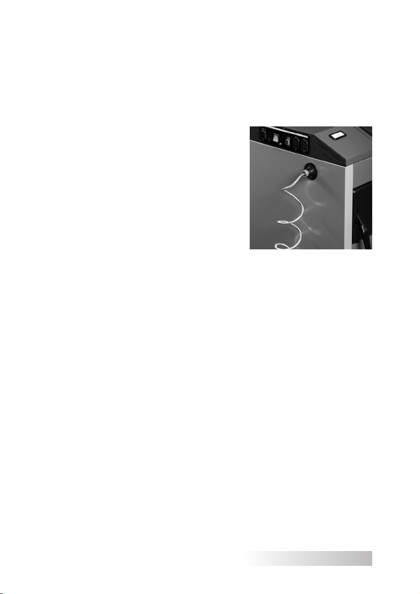
A descriptive identification of cables and sensors was used, and plugs of various shapes and colours. An additional label on the boiler "connect cables according to description".
A controller and devices working with it operate under voltage of 230 V, therefore, all connections can only be made by a person having required qualifications
(Polish Electricians Association licence up to 1kV).
All works should be performed with power supply switched off and all required
safety rules for servicing of electrical devices observed (ensure the plug is unplugged from the mains!). Any attempt to perform unauthorised repairs/changes
in the control system may result in electric shock and loss of the guarantee. Additionally electrical equipment is labelled with pictograms warning about the hazard.
42
Page 43

An attention should be paid to route cables supplying energized equipment away from the boiler components that become hot during operation
(flue, doors).
It is recommended to connect the heating device on a separate power circuit
with a protective device in the main switchboard.
An emergency power supply for the heating system (controller, fan, gearmotor,
circulatory pumps, mixing valves with an actuator) should be provided in the event
of power outage, from additional equipment: UPS with a sine wave output or a
power generator.
8. GUIDELINES FOR USE AND OPERATION
NOTE!
Before starting operation an experienced installer should train the
user in rules for operation and maintenance of the boiler and the
whole heating system. A person operating the boiler should be ac-
quainted with statuses of the incorrect device operation and with
procedures for dangerous situations.
8.1. FILLING WITH WATER
Before the first start-up of the boiler, the water tightness test of the
whole heating system should be performed. Before the tightness test is
started, the whole system should be effectively rinsed with water to remove any possible contaminations which could affect the boiler operation.
Water used to fill the boiler and the heating system should be clean,
free of aggressive chemical compounds or oil, and meet requirements
of current regulations (PN-C-04607:1993 Water in heating systems – Requirements and tests concerning water quality).
43
Page 44

Water for filling of the system should meet the following require-
ments:
• pH: 8.0–9.0 – in a copper system or systems of combined materials
steel/copper; 8.0–9.5 – in a system of steel and cast iron; 8.0–8.5 –
in a system with aluminium radiators.
• total water hardness ≤ 4.0 mval/l (11.2 °dH /German degrees/).
• free oxygen content ≤ 0.1 mg O2/l
Temporary hardness caused by hydrogen carbonates that are thermally unstable and when heated are transformed into water-insoluble
carbonates deposited as limescale. Some of limescale is deposited on
the system components and some on the boiler components, mainly the
exchanger. Limescale has very good thermal insulation properties, reducing heat absorption by boiler water and resulting in overheating of the
exchanger and, in consequence, in its destruction.
The boiler and the whole system should be filled with water through the
boiler discharge connector. This operation should be conducted slowly, to
ensure the air is removed from the system. The system is completely filled
when water flows out from the overflow pipe (in an open vented system).
When the central heating system is filled with water, it is recommended
to loosen screws at the connection between the boiler and the system (at
the hot water connector). When water flows out, tighten the screws.
The open vented heating system is in a direct contact with air, resulting
in water evaporation and a need to replenish it.
NOTE: It is forbidden and unacceptable to replenish water in the
event of the system failure – when there is no water in the boiler and
the boiler is very hot, because this may result in damage or cracks!
When the heating season is over do not discharge water from the system and the boiler. Whenever necessary, after cooling water is discharged
through the boiler discharge connector to a sink or a drain.
8.2. BOILER FIRING AND OPERATION
Firing of fuel in the boiler should be started after ensuring that a heating system
is filled with water and this water is not frozen. The boiler and threaded connections should also be checked for any water leakage.
It should also be remembered that the stake must be warmed up before
the first start-up.
This activity aims at ensuring correct conditions for correct burning of
basic/alternate fuel. For this purpose, burn a small amount of finely chopped
wood and crushed paper on the furnace with a water-cooled grate. When a
correct flue gas flow is created in the stack, the stack is warmed up and the
actual firing process can start.
44
Page 45

NOTE:
When a supply ventilation is not installed or is obstructed, this may lead
to consequences including generation of smoke or inability to reach the
required temperature.
When a supply ventilation is not installed, this may result in generation of
large quantities of flammable, highly-explosive gases (a risk of damage to
the flue pipe).
8.2.1. BOILER FIRING AND OPERATION IN AN AUTOMATED MODE
AUTOMATIC FIRING.
The burner in the SAS AGRO-ECO boiler is lit automatically with an integrated
electrical lighter. Therefore, the boiler start-up (furnace firing) is just limited to activation of the "FIRING" function in the controller menu.
NOTE:
The fuel tank and the fuel transport pipes are delivered without fuel. Therefore,
for a correct firing process they must be filled. Therefore, fuel should be loaded
into the tank, and then the feeder should be started in the manual mode to fully fill
the transport screws with fuel.
The feeder filling can be monitored from the furnace side through a feed door.
Poured surplus fuel must be removed from the furnace (e.g., pushed into the ashbox). It is forbidden to leave surplus fuel as the specified initial firing dose of fuel
will be poured automatically when the firing process is started. Note! Excessive
amounts of fuel at the firing stage may result in generation of large quantities of
flammable, highly-explosive gases (a risk of damage to the flue pipe).
The procedure described above is required both for a new boiler (first start-up),
and in the event the fuel tank is completely emptied. During normal operation of
the boiler fuel in the tank must be replenished regularly.
Warming up of the flue pipe and filling of the transport screws has a significant
effect on a correct and safe firing process. When the above recommendations are
performed, start the automated firing process with an electrical lighter (see the
controller operation and maintenance manual).
A person operating the boiler should be aware that some boiler surfaces are
hot, and safety gloves must be worn before touching them! Safety goggles should
also be worn (hot surfaces are labelled with a pictogram).
45
Page 46

Flue gases emitted from an obstructed stack are hazardous. The stack
and the connector should be kept clean; they should be cleaned according to
the manufacturer instruction. Boiler flue gas ducts should be kept clean. Use
only recommended types of fuel.
In the boiler firing mode the regulator automatically controls the fuel feeder
operation – supplied fuel is delivered to the grate, and at the same time an electrical lighter is activated. During firing the controller controls the status of the firing
process by continuously monitoring the flue gases temperature. When flame is
detected in the furnace the electrical heater is switched off, and the boiler automatically goes into the operational mode. The amount of air supplied by the blower
fan and a level of fuel supply to the furnace is controlled automatically according
to predefined optimum parameters specified for a given type of fuel (maintenance
parameters).
NOTE:
When fuels of poorer quality (e.g.: with a tendency to form slag, with high
ash content) are used, process parameters (controller settings) should be
adjusted accordingly.
After a single firing the boiler operation is, in general, maintenance free, and
the burning process is continuous. Further boiler operation is limited to replenishing of the fuel tank and removing deposited ash from the ash-box drawer .
A boiler room with a solid fuel automated boiler requires periodic monitoring. During boiler operation certain daily activities must be performed, to
prevent emergency situations.
When fuel is loaded into the hopper, it should be ensured that the fuel
does not contain larger pieces (e.g., foreign bodies), and in particular stones,
which may block the feeder!
The controller settings should be adjusted according to current temperatures
outside and to quality of fuel used, according to the controller operating manual
attached to this documentation (Chapter Programming Boiler Operation Parameters).
46
Page 47

Activities related to controller operation should be performed according
to procedures included in the controller operating manual.
Depending on the weather conditions, burning intensity and the boiler heat
output should be adjusted accordingly, regulating a temperature of water leaving
the boiler (or, when the three- or four-way valve is installed, by changing settings
of the control shutter).
The controller simultaneously controls operation of pumps: central heating, domestic hot water, and mixing (when the heating system is equipped with pumps).
It is not recommended to open any door during the boiler operation, as this
may cause flue gas return to the hopper. During firing smoke can penetrate into
the boiler room or retting (sweating) of the boiler. When the boiler and the flue pipe
are warmed these adverse effects should be reversed.
In the central heating system, the heat demand changes with changes in the
external conditions, i.e., time of the day and changes in the temperature outside.
The temperature of water leaving the boiler also depends on the building energy
performance, i.e., on construction materials, particularly insulation, used for its
construction.
MANUAL FIRING
When the furnace firing with the heating spiral fails (alarm status: "FAILURE OF
FIRING WITH HEATER"), the heating spiral may be damaged. In such situation
the following should be checked: 1° whether there is fuel in the hopper and the
gearbox is blocked by, e.g., undesirable object present in the tank, 2° whether the
furnace is not filled with excessive amounts of ash preventing fuel firing with the
heater. When it is found that the heating component is really damaged, start the
burner in the manual firing mode according to the following order:
1. The furnace must be cleaned of embers and soot, and the burner controller
must be switched off
2. Load fuel on the furnace grate in the manual mode
3. Pour firing fuel over fuel, wait until it is partly absorbed
4. Light it
5. Start the controller selecting the function "FIRING"
A person operating the boiler should be aware that
some boiler surfaces are hot,
and safety gloves must be worn before touching them!
47
Page 48

8.2.2. BOILER FIRING AND OPERATION IN AN "EMERGENCY BURNING"
(STEEL GRATE)
Before the firing procedure is started, open the feed door; the clean out hatch
door and the ash-box door must be completely closed. An emergency steel grate
must be installed in the furnace chamber, in brackets designated for its installation
– (the steel grate belongs to auxiliary equipment).
To prevent flue gas return to the hopper during the emergency burning of the
fuel (on the additional grate) it is recommended to fill the fuel tank, at least in part,
to prevent smoke from coming through the hopper.
Firing should be performed slowly, starting with balls of crumpled paper and
wood. When the initial fuel dose is lit, the boiler furnace chamber can be filled
with fuel through the feed door, after the ash-box door is closed. Then determine
settings of an air-dosing flap in the ash-chamber box using a control screw or a
draught regulator, to achieve required heat output and a set temperature.
When the fire in the boiler is extinguished, clean the furnace and air the boiler
ducts during firing, and restart firing.
During normal operation of the boiler in the "emergency burning" mode the
burning process requires periodic replenishment of fuel in the furnace chamber.
In the emergency mode, a single dose of fuel is sufficient for several hours of
the boiler operation, depending on the obtained boiler output.
8.3. BOILER CLEANING
For economic fuel consumption and to obtain declared boiler output and heat
effectiveness, it is necessary to maintain required cleanness of the burner furnace
space and the exchanger convection ducts.
In the furnace space particular attention should be paid to periodic cleaning of
micro-gaps in the automated furnace plate and air distribution apertures in the furnace side walls. Also (side/top) ceramic panels require periodic cleaning. Scalefree surface of the exchanger ensures correct heat transfer and maintaining of a
correct temperature in the furnace.
The convection ducts, in which air-born ash is deposited, should be regularly
cleaned, every 3–7 days, in particular, when the boiler is used in the "emergency
furnace" mode. Relevant tools delivered with the boiler should be used for this purpose. Cleaning of the convection ducts is facilitated by the front clean out hatch
door and the firing/feed door. Additionally, an air chamber located in the back part
of the boiler should also be cleaned periodically, because ash falling from the automated furnace plate collects there. It is cleaned through the side clean out hatch.
When the ducts are thoroughly cleaned, the flue and the stack connecting
duct should be cleaned. After cleaning these openings must be tightly closed. At
the factory, the boiler was equipped with a set of ceramic sealant (see inspection/
clean out doors/openings). Regular inspection of the sealant condition is recommended, and its replacement when any wear is discovered.
48
Page 49

NOTE:
From the moment of boiler firing to its putting off the boiler operation is
monitored with a flue gas sensor installed in the flue. It is recommended to
clean the sensor surface regularly, to ensure a correct temperature read-out
in the flue gas duct and correct control over the burning process.
Cleaning of a flue pipe is also of importance for correct operation of the boiler.
8.4. END OF BURNING
When the heating season is over or during planned downtime of the boiler, the
burner should be switched off by selecting a put off mode on the controller, and
residues of the burning process must be removed through the furnace door to the
ash box.
NOTE: It is forbidden to use water in the boiler room to extinguish fuel!
In the event of the emergency extinguishing, the fired fuel must be removed into metal containers and removed from the boiler room, or sand
should be poured over fuel burning in the furnace.
When the heating season is over or during planned downtime of the boiler wait
until the supplied dose of fuel burns out. When the boiler is put off and cooled,
remove all residues of burned fuel from the furnace, and perform cleaning and
maintenance operations for the whole boiler. Maintenance activities should be performed on inner partitions in the furnace chamber (by wiping them with oil). In particular, the mechanism feeding fuel into the furnace chamber should be secured
for the break in boiler operation
It is recommended to leave doors open during the boiler downtime, to protect
the exchanger against moisture condensation (premature corrosion). When the
boiler is not in operation, once a week start the feeder mechanism, the moving
grate mechanism, the blower fan, and the circulatory pumps. This prevents blockade of the moving components.
Do not discharge water from the boiler and the system for the break in the
heating season.
49
Page 50

9 CONDITIONS FOR SAFE OPERATION
To maintain safe operational conditions for the boiler, the following
rules must be observed:
• the boiler can only be operated by adults, according to guidelines
provided in the documentation supplied together with the device;
• all connections to the power supply system can only be made by a
person holding relevant qualifications – Polish Electricians Association licence up to 1kV;
• children cannot remain unattended in the boiler vicinity, or have access to the controller and to moving components of the boiler;
• the boiler and the associated system must be kept in the correct
operational condition, and in particular, system tightness and tightness of doors and clean out hatches must be ensured;
• maintain order in the boiler room and do not stack any objects not
used for boiler operation or flammable materials;
• during winter avoid breaks in heating to prevent freezing of water
in the system or its part. Freezing, particularly of safety (overflow)
pipes is very dangerous, as it may result in the boiler damage;
• it is forbidden to fire the boiler using flammable materials such as
petrol, kerosene, or solvents, as this may result in explosion or
burning of the user;
• before each firing and regularly during operation check the amount
of water in the heating system and ensure the valves between the
boiler and the system are opened;
• during the boiler operation the heating water temperature cannot
exceed 85 °C;
• in the event of the system failure, when there is no water in the boiler do not replenish it when the boiler is very hot, because this may
result in the boiler failure;
• all activities related to the boiler operation should be performed in
protective gloves and with particular care observed; all boiler defects must be remedied immediately.
NOTE:
The boiler must be regularly cleaned of soot and tar – any deposits on
convection duct walls affect correct heat transfer from the exchanger,
reducing the device performance and increasing fuel consumption.
50
Page 51

10. SERVICE AND MAINTENANCE
OF A FEEDER AND A BURNER
The biomass burner is designed in a way not requiring complicated
operation and expensive maintenance. However, its correct operation
(influencing boiler performance and burning economy) requires certain
rules to be observed during the feeder operation and regular performance of certain activities.
1. A periodic inspection of the furnace in operation can only be performed through the furnace door.
2. Remove regularly sintered and unremoved slag when present in
large quantities in the boiler furnace (it may block air supply).
3. Check the fuel level in the tank.
4. Fuel loaded into the tank must be dry.
5. Check whether no dust or other waste accumulated in the tank and
the feeder cover pipe, and remove it when necessary.
6. Check condition of air nozzles and patency of air outlets.
7. Periodically clean dust and residues of coal or ash from the feeder.
8. Regularly clean the motor casing using a dry cloth.
9. Do not use any solvents for cleaning as they may damage sealing
rings and gaskets.
10. When the boiler, together with the feeder, is removed from operation, quarterly start screws, the moving grate mechanism and the
blower fan for 15 minutes – thus preventing any blocking of the
moving components.
11. Check for accumulation of dust or other waste in the air chamber –
through a side clean out hatch (see Fig 6, Fig. 7).
12. Regularly monitor condition of screw connections in: fuel tank with
the fuel feeder, feeder with the boiler, and closing of the side clean
out hatch, and adjust the front door setting with hinges and adjustment screws, whenever necessary.
51
Page 52

11. STATUSES OF INCORRECT BOILER WORK
PROBLEM
Low heat
performance of
the device
Smoke
CAUSE/
APPEARANCE
contamination of flue gas ducts
no air supply to the boiler room
burning of incorrect fuel
boiler output incorrectly selected for
the heated surface
incorrectly designed and
constructed central heating system
incorrect operation of a controller, a
fan or a feeder
insufficient chimney draught
contamination of flue gas ducts
sealant sealing doors and clean out
hatch openings is worn
incorrect connection of the boiler
with a chimney stack
REMEDIES
clean the flue gas ducts through the
clean out hatch door
check the condition of the supply
ventilation in the boiler room, improve
its patency.
use fuel of adequate quality (see
chapter "Fuel")
adjust controller settings according to
the weather conditions and fuel type,
in particular, set a correct length of
break in feeding
when the controller does not work
correctly, check the controller operating manual
check chimney stack patency and
parameters (see a table specifying
appropriate chimney hight and
cross-section for a given boiler output), check whether the chimney does
not end below the highest roof ridge
clean the boiler through the clean out
hatch door
replace sealant sealing doors and
clean out hatch openings (this is a
wearable material subject to regular
replacement).
check correctness of the connection
between the boiler with a chimney
stack
52
very low atmospheric pressure
incorrect flue gas damper position
for chimney draught present
adjust the damper position when it is
closed too far, hindering flue gas flow
to the stack
Page 53

Sudden increase
in the temperature
and the pressure in
the boiler
Water leaking from
the boiler
"Rattling, firing" in
the boiler
valves in the system closed open the valves
expansion vessel is frozen
boiler "sweating, retting",
this is a natural phenomenon
resulting from temperature
differences in the boiler
air in the central heating system
and the boiler, e.g., due to incorrect
filling of the system and the boiler
with water
provide thermal insulation on the
expansion vessel
at each boiler start-up and after each
downtime "warm the boiler up", i.e.,
fire it to the temperature of 70 °C and
maintain this boiler temperature for
several hours
boiler warming up, i.e., maintaining
the temperature above 70 °C for
longer time until air bubbles are
completely removed from the boiler
bleed the central heating system
with vents
on the radiators
The fan does not
work correctly, The
feeder does not
work correctly
The moving grate
mechanism does
not work
does not start, whines, problems
with start-up, does not reach set
operating values
does not start, a message "Hall
effect sensor" appears
replace the fan capacitor (see the fan
casing), replace the feeder capacitor
(see the feeder casing)
clean the air chamber
of the burner, check the settings of
the grate positioning sensor (Hall
effect sensor), replace the sensor
(see the pellet feeder)
53
Page 54

12. PROTECTIVE DEVICES
To ensure possibly failure-free and safe operation, the boiler controller
is equipped with numerous protective devices. The software installed controls operation of semi-assemblies and performs monitoring and safety
operations to prevent hazardous conditions (e.g., power outage and its
restoration). When any incorrect status is found an audio alarm is activated, and a relevant message is shown on the display (see the controller operating manual). To eliminate the effect of voltage fluctuations or incorrect
voltage in the mains, a system controlling the fan rotational speed was
installed (the Hall effect sensor).
When the equipment is installed, each boiler undergoes a test of correct operation of the control system. The temperature regulator, wiring
and the supply terminal strip are installed in the insulation lid on purpose,
to eliminate access to locations posing a hazard of an electric shock. Appropriate tools must be used to remove them.
TEMPERATURE ALARM
This security device is activated only in the operational mode (when
the boiler temperature is below the set temperature). When the boiler temperature does not rise in the time specified by the user, the alarm is activated, the feeder and the blower are switched off, and the audio signal is
alarmed. The screen displays the following message: "Temperature does
not increase”. When the encoder is pressed, the alarm is switched off.
The controller returns to the last set operational mode.
AUTOMATED SENSOR MONITORING
When the central heating system, the domestic hot water sensor or
the fuel feeder sensor is damaged, the audio alarm is activated signalling
additionally a relevant defect on the display, e.g.: "Central heating sensor
damaged". The feeder and the blower are switched off. The pump works
regardless of the current temperature. When the central heating or the
feeder sensor is damaged, the alarm will remain active until the sensor
is replaced with a new one. When the domestic hot water sensor is damaged, press the encoder knob, switching off the alarm, and the sensor will
return to the central heating pump operation). The the domestic hot water
sensor must be replaced with the new one to enable the boiler operation
in all modes.
54
Page 55

TEMPERATURE PROTECTION
The controller is provided with additional software (digital) temperature protection against dangerous increase in the temperature. When the
alarm temperature (set within the 80 °C–85 °C range) is exceeded, the
blower fan and the fuel feeder are disconnected. At the same time, active
pumps start to work to distribute heat in the system. When the boiler alarm
temperature is exceeded, the audio alarm is activated and the message
is displayed "Temperature too high”. When the temperature returns to
the safe value, the alarm is switched off by pressing the encoder, and the
regulator returns to the last set operating mode.
THERMAL PROTECTION
The boiler controller is equipped with the safe temperature limiter
protecting against boiler overheating (water boiling in the system) when
the controller is damaged. The safe temperature limiter is a protecting
device in form of a bimetallic sensor installed near the boiler water temperature sensor, cutting off power supply to the blower fan and the fuel
feeder when the limit temperature exceeds 90 °C (central heating pump
remains switched on). The equipment cannot be restarted automatically,
even when the temperature is lowered. The user must switch them on, resetting the sensor (with the STB button) after the temperature is reduced.
When this sensor is damaged or overheated, the fan and the feeder are
switched off (do not work either in the manual or the automated mode).
FUEL TANK SECURITY DEVICES
To ensure safe operation of the boiler, the fuel feeder is equipped with a
security system consisting of several steps. Components of this system
include a protection against flashback to the fuel tank through the
feeder (a mechanism of two transport screws separated with a transfer duct, a temperature sensor in the fuel route) and additional protection against overheating – a thermal switch installed in the boiler. The
fuel from the fuel tank is transported to the furnace chamber in such way
as to eliminate a risk of flashback to the fuel tank during normal operation
or feeder downtime, as well as during power outages or power supply
failure. The mechanism protect against uncontrolled flashback into the
fuel tank without a need to install a water extinguishing system. Safe fuel
transport is ensured by location of loading openings for fuel distribution
pipes and by a distance between these pipes. The screw conveyors are
rotated by gear wheels driven by a chain driven by a gearmotor. For safety
reasons a flap closing the fuel tank during the biomass burning must be
tightly closed.
55
Page 56

The controller is additionally secured against flashback to the fuel tank
(hopper). The boiler is equipped with a feeder pipe sensor measuring
temperature near the fuel tank. When the temperature increases significantly (when the set temperature is exceeded), the internal controller
software automatically activates procedures protecting the boiler against
overheating or fire in the fuel feeder. The alarm is activated and the feeder
is started cyclically, moving fuel to the furnace chamber to reduce the
temperature of the feeder components.
For safety reasons, the fuel tank is separated from the boiler body – a
naturally ventilated space is provided (separate casings, thermal insulation of the exchanger, ceramic sealant, and additional insulation of the
feeder components).
The boiler is equipped with a tight fuel tank with a pressure equalising
system.
FUSE
A controller is equipped with WT 6.3A tube fuse links protecting the
mains.
NOTE:
Do not use a fuse of a higher value. Installation of a larger fuse may
damage the controller.
PROTECTION OF THE SCREW CONVEYOR AND THE GEARBOX
The motor is additionally protected against overload in form of a thermal fuse, which automatically switches the feeder off in the event of overheating.
PRESSURE RELIEF VALVE
The boiler is equipped with a factory-installed with the 2.5 bar pressure
relief valve, being an additional protecting device against the pressure
increase when water freezes in part of the system, and in the expansion
vessel in particular. The installer is obliged to connect a pipe discharg-
ing water from the pressure relief valve to the drain or at the lowest
possible level near the floor.
56
Page 57

Additionally, an analogue thermometer is installed for a control temperature readout or in the event of the control system failure, when boiler operates in the "emergency burning" mode. The heating system should be
equipped with a measuring and monitoring device for pressure readout,
in form of a manometer.
THERMAL PROTECTION VALVE PROTECTING AGAINST OVERHEATING (optional)
In its standard version, the SAS AGRO-ECO boiler is equipped with a
connector for installation of the temperature sensor with a capillary tube
(does not apply to boilers of output exceeding 100 kW); the thermostat
valve (optional), e.g., Regulus type BVTS is a thermal protection device for
a boiler installed through the heat exchanger in an open vented system
with the plate exchanger or for the boiler installed in the sealed system,
e.g., SYR, type 5067. When the boiler is overheated (jacket temperature
above 95 °C) the thermal protection valve installed on the boiler is opened,
the water supplied from the water supply system cools the boiler, flows
from the system to the cooling well, and then to the sewage system. A
detailed description of the valve operation and connection is described in
Chapter 7.5 Boiler connection to a heating system.
When the thermostat valve is not installed, the connector must be secured with a plug.
13. DELIVERY TERMS AND CONDITIONS
The boilers for sale are delivered in an assembled condition, with a set
of tools for they operation and with the operation and maintenance documentation (see Chapter 4 "Setting a boiler").
The boilers are installed at the factory on a transport pallet (excluding
boilers above 48 kW), protected with a plastic film against weather conditions. Brackets are installed for boiler transport with a pallet/fork lift truck.
Individual boiler components can be dismounted: the fuel feeding system,
the fuel tan, and the temperature sensors, for boiler transport and installation in the boiler room.
When the fuel feeder must be dismantled, it can only be reinstalled by
a qualified installer!
Incorrect connection of cables may damage the regulator.
57
Page 58

NOTE:
Boilers must be transported in a vertical position! Store in roofed
and well-ventilated rooms! Secure the load against damage! When
the boiler is damaged (in transport), do not use it but contact the
manufacturer maintenance service.
14. BOILER DISPOSAL
Components used in the boiler are made of materials which physical
state and chemical activity changes at temperatures significantly exceeding temperatures that can be reached during normal operation of the boiler. Materials used for construction of the device do not emit substances
hazardous to the environment, even in conditions exceeding normal operational conditions of the boiler.
To dispose of the boiler, transfer the used device to a specialist disposal company, in accordance with current specific regulations in force in a
country of destination. Components protecting the boiler for the transport:
plastic film, bags, plastic materials, should be transferred to a relevant
waste collection entity. The SAS AGRO-ECO boiler is equipped with digital equipment subject to selective collection of electrical and electronic
equipment (a sign of a crossed-out basket on a nominal plate). The steel
structure of the boiler should be disposed of as steel scrap. Before scrapping, disconnect the controller, the fan, the gearmotor, and power supply
cables. Insulation materials (e.g., mineral wool, sealant, etc.) should be
transferred to a relevant waste collection entity. The waste collection place
should be specified by relevant municipal or commune services.
58
Page 59

15. WARRANTY TERMS AND CONDITIONS
1. The manufacturer grants to the Buyer a warranty for the SAS AGROECO boiler under terms and conditions specified in this warranty. It
is confirmed with the company seal.
2. The manufacturer guarantees efficient work of the boiler when it is
installed and operated according to all conditions and guidelines
specified in the operation and maintenance documentation.
3. The Buyer is issued with the operation and maintenance documentation, specifying principles for correct operation of the boiler,
together with the warranty terms and conditions. It is mandatory
to become acquainted with the operation and maintenance documentation.
4. The warranty term begins with a day of issuing the subject matter
of the agreement to the Buyer and is:
a. 5 years *for efficient operation of the boiler
b. 2 years for electronic and automatic sub-assemblies installed in
the boiler and manufactured by other producers:
• Driver
• Module controlling burner operation
• Blower fan
• Pressure relief valve
• Gearmotor
• Drive motor for moving grates
• Electrical heater (fuel lighter)
• Automated fuel feeding system and its components
• Analogue thermometer
5. The warranty does not cover components subject to wear and tear:
• Screws, nuts, handles
• Sealant (sealing components)
• Capacitor (see the blower fan, the gearmotor)
• Hall effect sensor
• Ceramic panels (see Table 2)
6. In consequence of any repairs of the boiler or changes in its design
or insulation made by the Buyer or other third persons during the
warranty period the warranty terms and conditions become invalid.
7. All damages resulting from incorrect operation, incorrect storage,
improper maintenance not conforming to the operation and
maintenance documentation, or other reasons not attributable to
the manufacturer result in loss of the warranty.
* for boilers above 48 kW, the warranty period is 24 months.
59
Page 60

8. Only original spare parts offered by the Metal Products and Boiler
Production Plant "SAS" should be used. The manufacturer shall
not be held responsible for defective work of the SAS AGRO-ECO
boiler when incorrect spare parts are used.
9. The sealing rope in the clean out, furnace or ash-box doors is
not covered by the warranty. It is a wearable material for periodic
replacement.
10. During the warranty period the manufacturer provides free of charge
repair of the subject matter of the agreement within 14 days of a
defect notification.
11. A defect covered by a warranty repair should be notified immediately
when that defect is discovered.
12. The complaint should be sent to the manufacturer address.
13. When the party submitting the complaint prevents twice performance
of the warranty repair despite the guarantor notifying its readiness
for such performance, it shall be understood as a waiver of the
claim included in the warranty notification.
14. Replacement of the boiler is acceptable when the guarantor decides
it cannot be repaired.
15. When it is found that the service request was unfounded, the
customer shall bear costs of the technician travel and work Before
you call the maintenance service, please become acquainted with
chapter "Statuses of incorrect boiler work". We are always ready to
provide advice and assistance by phone.
16. The correctly filled in warranty card, with a signature and a seal of
the seller and a date of the sell is the only basis for free of charge
repairs.
17. This operation and maintenance documentation and the warranty
card must be delivered together with the boiler should the title to it
be transferred on another person.
18. The complaint notification should include:
• boiler details from the nominal plate: type, size (nominal
output), serial number/production year
• purchase date and place
• controller/feeder/fan model
• (see operation and maintenance documentation of subassemblies installed in the device)
• boiler defect description
• Boiler owner address and telephone number
60
Page 61

NOTE: The manufacturer is entitled to introduce possible design
changes in the boiler resulting from a technological progress and product
modernisation. These changes may not be included in this operation and
maintenance documentation, while the basic described features of the
product will be maintained.
All issues and queries concerning operation of SAS boilers should be
sent to:
ZAKŁAD METALOWO-KOTLARSKI „SAS”
Owczary, ul. Przemysłowa 3, 28-100 Busko-Zdrój
Tel. 41 378 46 19, fax 41 370 83 10
e-mail:biuro@sas.busko.pl
maintenance service: Phone 41 378 15 00, 41 378 50 80, serwis@sas.busko.
pl
technical assistance for SAS boilers: phone 505 950 252
TECH controllers: Phone 33 875 19 20
RECALART controllers: Phone 77 46 25 877; 794 668 232
You can also find operation and maintenance documentation for SAS
boilers and installed sub-assemblies and controllers, as well as all necessary
information at our website:
www.sas.busko.pl
Operation and maintenance documentation in a version valid from March 21, 2016.
61
Page 62

SERVICE REPAIRS
62
Page 63

WARRANTY CARD
According to the specied terms and conditions,
a 60 (24*) months warranty is granted for the low temperature
heating boiler, type SAS AGRO-ECO, operated according
to operation and maintenance documentation
Boiler No. – .....................................................
Heat output – .....................................................
Heating surface – .....................................................
Year of production – .....................................................
………………………………………………………
Manufacturer signature
and company stamp
* for boilers above 48 kW, the warranty period is 24 months.
………………………………………………………
………………………………………………………
Seller signature
and company stamp
Date of sale
63
Page 64

MODERN AND ENVIRONMENTALLY FRIENDLY
CENTRAL HEATING BOILERS
water-based, steel, low temperature,
with a certificate of energy and emission tests
Manufactured in several variants:
UNIVERSAL BOILERS
for burning of coal,
fine coal and fuel wood
(with/without a blower)
BOILERS WITH AN ECO FEEDER
adapted to fine coal and pea coal burning.
Equipped with a traditional furnace
with a water-cooled grate.
BOILERS WITH A FEEDER: SMART, GRO-ECO
adapted to power pea coal burning. Equipped
with an alternate furnace with a water-cooled grate.
BOILERS WITH A SLIM OR MULTI FEEDER
adapted to power pea coal burning. Equipped
with an alternate furnace with a water-cooled grate.
BOILERS WITH A MULTI FLAME BURNER:
BIO SMART, BIO SLIM, BIO MULTI, BIO GRO-ECO
pellet-fired
AGRO-ECO BOILERS
Adapted to burning of
biomass: oats, pellets,
dry fruit stones, etc.
 Loading...