


98647-002-37
Sartorius
YDK 01, YDK 01-0D, YDK 01LP
Density Determination Kit
User’s Manual

2
YDK 01, YDK 01-0D
9
8
7
2
1
3
4
56

3
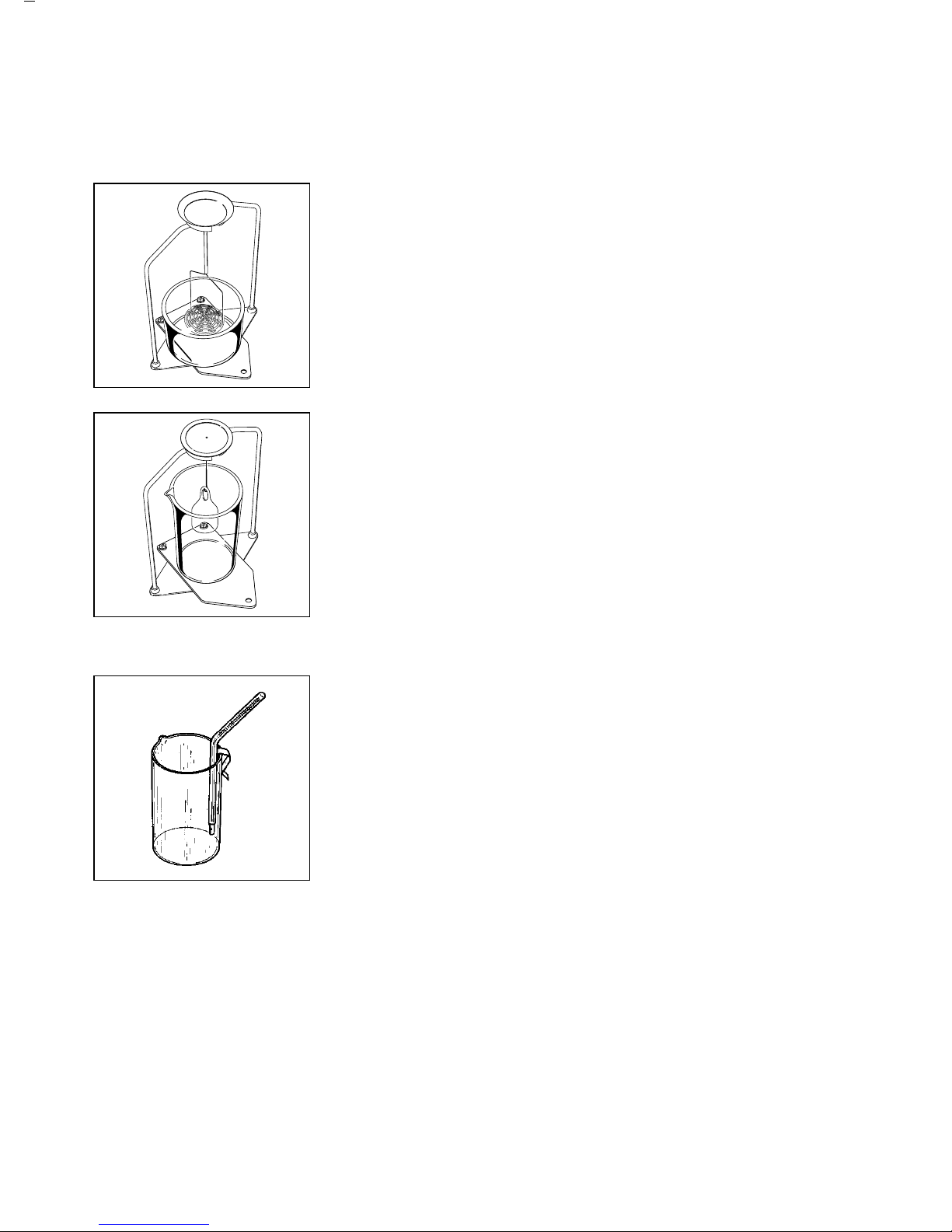
Kit Components
Die Bestandteile
Contenu de la livraison
1 Beakers (76 mm Ø and 55 mm Ø)
Bechergläser
(Ø 76 mm u. Ø 55 mm)
Béchers (Ø 76 mm et Ø 55 mm)
2 Bar frame
Gestell
Structure de suspension
3 Thermometer with retainer clip
Thermometer mit
Befestigungsklemme
Thermomètre avec clip de fixation
4 Glass plummet
Glassenkkörper
Plongeur calibré en verre
5 Sieve for immersing samples
(pan hanger assembly)
Tauchsieb
Panier pour échantillons «flottants»
(ensemble à suspendre)
6 Sample holder
(pan hanger assembly)
Tauchkorb
Panier pour échantillons
(ensemble à suspendre)
7 Metal platform
Brücke
Pont métallique
8 Gasket for ME models
Dichtring für ME-Modelle
Anneau d’étanchéité
pour modèles ME
9 Adapters (3)
Adapter (3 Stück)
Adaptateurs (3)

4
9
10
8
7
2
1
3
4
56
YDK 01LP

5
Kit Components
Die Bestandteile
Contenu de la livraison
1 Beakers (76 mm Ø and 55 mm Ø)
Bechergläser
(Ø 76 mm u. Ø 55 mm)
Béchers (Ø 76 mm et Ø 55 mm)
2 Bar frame
Gestell
Structure de suspension
3 Thermometer with retainer clip
Thermometer mit
Befestigungsklemme
Thermomètre avec clip de fixation
4 Glass plummet
Glassenkkörper
Plongeur calibré en verre
5 Sieve for immersing samples
(pan hanger assembly)
Tauchsieb
Panier pour échantillons «flottants»
(ensemble à suspendre)
6 Sample holder
(pan hanger assembly)
Tauchkorb
Panier pour échantillons
(ensemble à suspendre)
7 Metal platform
Brücke
Pont métallique
8 Adapter for LA/LP models
with an analytical draft shield
Adapter für LA/LP-Waagen
mit Analysenwindschutz
Adaptateur pour modèles LA/LP
avec chambre analytique
9 Adapter for LA/LP models
without an analytical draft shield
Adapter für LA/LP-Waagen
ohne Analysenwindschutz
Adaptateur pour modèles LA/LP
sans chambre analytique
10 Compensating disk
for LA/LP 3200 D models
Ausgleichsscheibe für LA/LP 3200 D
Disque de compensation
pour modèles LA/LP 3200 D

Contents
Page
Kit Components 2
Getting Started 8
Methods for Determining Specific Gravity/Density 13
Sources of Error and Possibilities for Correction 14
Determining the Specific Gravity/Density 17
– of Solids 17
– of Solids with a Density <1g/cm
3
18
– of Liquids 21
Application in Legal Metrology 22
Tables 23
Density Values of H2O23
Density Values of Ethanol 24
Supplement 25
6

With this Sartorius Density Determination Kit
you have acquired a high-quality accessory to your
electronic balance.
This accessory kit will ease your daily work load.
Please read the Installation and Operating Instructions
carefully before setting up your density determination
kit and working with it.
If your balance is equipped with a density
determination program, you can have the rho values
calculated by the program.
In this case, please follow the operating instructions
in “Getting Started.”
Perform density determination as described in the
density determination program.
Important Note:
The YDK 01-0D density determination kit can be
used for determining the density of liquid according
to weights and measures regulations.
7

Getting Started
YDK 01, YDK 01-0D
You can use the density determination kit, YDK 01or
YDK 01-0D, with the following balances:
– ME series balances (Genius series)
– BA balances with a readability ≤ 0.1mg
– BP/LA balances with a readability ≤ 0.1mg
– MC balances with a weighing range of 210 g
and up (Micro series)
– RC balances (Research series)
Preparing the Bar Frame
You must mount the adapter before the bar frame can
be placed on the balance.
Please use the adapter that is appropriate for the
balance you are using.
(approx. dimensions)
8 mm Ø, height 41.3 mm – ME balance
with gasket
7 mm Ø, height 16.5 mm – BA, BP*, MC and
RC balances
12 mm Ø, height 25.5 mm – BP**/LA balances
with a readability
≤ 0.1mg
** = BP 210 D, BP 300 S, BP 210 S, BP 160 P,
BP 110 S
** = BP 211 D, BP 301S, BP 221S, BP 161P,
BP 121S
8

Screw the appropriate adapter into the underside
of the bar frame base.
Now remove the following components from
the balance:
– weighing pan
– compensating ring for BA and BP balances
– pan support for BA and BP balances
Place the frame in the weighing chamber. The
wedge-shaped opening at the top of the frame must
face the direction from which the sample holder
(sieve/glass plummet) will be placed into the frame.
Always use the metal platform to hold a beaker.
Please position this platform through the frame so it
rests evenly on the base of the weighing chamber.
If you are using an BA, BP or ME balance, turn the
platform so it rests on the pins which are far apart. For
RC and MC balances, the platform should rest
on the pins which are closer together.
9

YDK 01LP
You can use the YDK 01 LP density determination kit
with LA/LP balances with a readability of 1mg.
Installing the Density Determination Kit
● Remove the draft shield cover, glass plate,
weighing pan and base from the balance
LA/LP Balances, Except Model LA/LP3200D
● Place the components on the balance
in the following order:
– Compensating ring
– Bar frame
k The wedge-shaped opening at the top of the bar
frame should face the direction from which
the sample holder (pan hanger assembly/glass
plummet) will be placed on the balance
LA3200D, LP3200D Balances
● Place the components on the balance
in the following order:
– Short adapter
– Compensating disk
– Bar frame
k The wedge-shaped opening at the top of the bar
frame should face the direction from which
the sample holder (pan hanger assembly/glass
plummet) will be placed on the balance
LA/LP Balances, Except Model LA/LP3200D
with the YDS01LP Draft Shield
● Place the components on the balance
in the following order:
– Longer adapter
– Bar frame
k The wedge-shaped opening at the top of the bar
frame should face the direction from which
the sample holder (pan hanger assembly/glass
plummet) will be placed on the balance
10

LA3200D, LP3200D Balances with the YDS01LP
Draft Shield
● Place the components on the balance
in the following order:
– Longer adapter
– Compensating ring
– Bar frame
k The wedge-shaped opening at the top of the bar
frame should face the direction from which
the sample holder (pan hanger assembly/glass
plummet) will be placed on the balance
Beaker/Immersion Device
● Use the metal plate to support the beaker.
Place it on the bar frame base and then set both
on the balance.
The choice of the beaker and the immersion device
depends on the sample to be determined (see below).
To determine the specific gravity of solids when
their density is greater than that of the liquid in which
the sample is immersed, use:
– 76 mm Ø beaker and sample holder
11
To determine the specific gravity of solids when
their density is less than that of the liquid in which the
sample is immersed, use:
– 76 mm Ø beaker and sieve for immersing
the sample
To determine the density of liquids:
– 55 mm Ø beaker and glass plummet
Thermometer
If necessary, attach the thermometer to the rim of the
beaker using the retainer clip.
12

Methods for Determining Specific Gravity/Density
The Archimedean principle is applied for determining the specific gravity of a solid
with this measuring device:
A solid immersed in a liquid is exposed to the force of buoyancy. The value of
this force is the same as that of the weight of the liquid displaced by the volume
of the solid.
With a hydrostatic balance which enables you to weigh a solid in air as well as
in water, it is possible to:
determine the specific gravity of a solid if the density of the liquid causing
buoyancy is known:
W (a) · ρ (fl)
ρ =
W (a) – W (fl)
or
determine the density of a liquid if the volume of the immersed solid is known:
G
ρ (fl) =
V
where:
ρ = specific gravity of the solid
ρ (fl) = density of the liquid
W (a) = weight of the solid in air
W (fl) = weight of the solid in liquid
G = buoyancy of the immersed solid
V = volume of the solid
13

Sources of Error and Possibilities for Correction
The formula on the previous page for determining the specific gravity of solids is
sufficient to obtain an accuracy of one to two decimal places.
Depending on the accuracy you require, consider the following error and
allowance factors.
– The density of the liquid causing buoyancy depends on its temperature
– Air buoyancy during weighing in air
– The change in the immersion level of the pan hanger assembly when the sample
is immersed
– Adhesion of the liquid on the suspension wire of the pan hanger assembly
– Air bubbles on the sample
Some of these errors can be corrected by calculation. To do so, it is necessary to
proceed as follows:
– measure the temperature of the reference liquid and correct its density
accordingly
and
– define the inner diameter of the container which holds the reference liquid.
Dependence of the Liquid Density on Temperature
The density of the liquid causing buoyancy depends on the temperature.
The change in the density per °C change in temperature is in the range of
– 0.02% for distilled water
– 0.1% for alcohols and hydrocarbons.
In other words, this can show up in the third decimal place during specific
gravity/density determination.
14

To correct the liquid density for temperature, proceed as follows:
– measure the temperature of the liquid using the thermometer that comes
with the kit
– use the table at the back of this manual to find the density of the most commonly
used liquids, water and ethanol, at the temperature measured, and use this
density for the value ρ (fl).
Air Buoyancy
A volume of 1cm of air has a weight of approximately 1.2 mg, depending on
its temperature, humidity and air pressure. When weighed in air, a solid is
buoyed by a corresponding force per cm3of its volume. The error that results if the
air buoyancy is not allowed for shows up in the third decimal place and should
therefore be corrected.
The following formula allows for air buoyancy:
W (a) · [ρ (fl) – ρ (a)]
ρ =+ ρ (a).
W (a) – W (fl)
Where ρ (a) = 0.0012 g/cm3= Density of air under standard conditions
(temperature 20°C, pressure 101.325 kPa).
Depth of Immersion
The pan for holding and/or immersing the sample during weighing in liquid
is rigidly attached to two wires and is immersed approximately 30 mm below the
surface of the liquid. Since the balance is tared before each measurement, the
additional buoyancy caused by the immersed part of the measuring device is not
allowed for in the specific gravity determination.
When a solid sample is weighed in liquid, a volume of the liquid will be displaced
which corresponds to the volume of the solid sample. This causes the attachment
wires of the pan hanger assembly to be immersed deeper and generate additional
buoyancy which introduces an error in the specific gravity determination.
15

Use the following formula to correct this error:
W (a) · [ρ (fl) – ρ (a)]
ρ =+ ρ (a)
0.99983 [W (a) –W (fl)]
Since the correction factor is determined exclusively by the geometry of the
measuring device setup, be sure to only use the large diameter beaker (76 mm)
from the kit when determining the specific gravity of a solid. The “Supplement”
to this manual shows how this correction factor is derived.
Adhesion of Liquid to the Wire
When the sample holder (or sieve) is immersed in liquid causing buoyancy,
liquid travels up the wire because of adhesion forces and generates an additional
weight in the range of a few milligrams.
Since the sample holder (or sieve) is in the liquid causing buoyancy during both
weighing in air and weighing in liquid, and the balance is tared at the beginning
of each measuring procedure, the effect of the meniscus can be disregarded.
To reduce the surface tension and the friction of liquid on the wire, add three
drops of a tenside (Mirasol Antistatic or an ordinary dishwashing detergent) to the
distilled water in the beaker.
Because of the liquid travelling up the wire, the weight may slowly change even
after the stability symbol “g” appears. Therefore, read off the weight immediately
after the “g” is displayed.
Air Bubbles
The measuring error caused by air bubbles adhering to the sample can be
estimated in the following manner. An air bubble with a diameter of 0.5 mm
causes an additional buoyancy of less than 0.1mg when a sample is weighed in
water. An air bubble diameter of 1mm causes additional buoyancy of 0.5 mg
and an air bubble diameter of 2 mm causes approx. 4.2 mg additional buoyancy.
Larger air bubbles must be removed with a fine brush or other utensil.
You can also wet the sample in a separate container before you weigh it.
16

Determining the Specific Gravity/Density
Determining the Specific Gravity of Solids
Preparation
(Distilled water is used in the description)
– Center the large-diameter beaker (76 mm Ø) on the metal platform
– Fill it so that the distilled water is approximately 5 mm below the rim
– Add three drops of tenside to the distilled water
– Attach the thermometer to the rim of the beaker using the retainer clip
– Clean the sample holder with a solvent (especially the wires that will be
immersed) and hang it from the frame
Measuring Procedure
Determining the Weight of a Sample in Air
– Tare the balance
– Place the sample on the upper pan on the frame and weigh
– Record the weight W (a)
Determining the Buoyancy G = W (a) – W (fl)
– Tare the balance with the sample on the upper pan on the frame
– Place the sample in the sample holder1)
– Record the absolute readout of the buoyancy “G,” which is displayed with
a negative sign
1
) If you remove the pan hanger assembly from the measuring device to do this,
make sure that no additional air bubbles are on it when you re-immerse it; it
is better to place the sample directly on the pan using forceps or a similar utensil.
17

Calculating the Specific Gravity
– Read off the temperature of the liquid
– Using the tables at the back of this manual, find the density ρ (fl) which
corresponds to the temperature measured for the liquid you are using
– Calculate specific gravity using the following formula:
W (a) · [ρ (fl) – 0.0012 g/cm3]
ρ = + 0.0012 g/cm
3
0.99983 G
W (a) and G in g; ρ (fl) in g/cm
3
G = W (a) – W (fl)
Determining the Specific Gravity of Solids with a Density Less Than 1g/cm
3
There are two different methods for determining the specific gravity of solids with
a density less than1g/cm.
Method 1:
For this method, distilled water is still used as the liquid causing buoyancy, but the
pan hanger assembly is replaced by the sieve for immersing samples.
To determine the sample’s buoyancy, float it on the surface of the water and then
immerse it using the sieve.
It is also possible to use forceps or a similar tool to place the sample directly under
the sieve (without removing the sieve from the frame).
If the buoyancy of the substance to be measured is so high that the weight of
the sieve is not enough to immerse the sample, increase the weight of the sieve by
adding an additional weight to the upper pan on the frame.
18

Method 2:
(for this method, use the sample holder)
Here, use a liquid for causing buoyancy with lower density than that of the solid
for which the specific gravity is to be determined. We have had good results with
ethanol (up to a density of approx. 0.8 g/cm3).
The density ρ (fl) of ethanol (with regard to its temperature) can be found in the table
in the supplement.
The negative effect of the liquid’s surface tension on the results is less noticeable
when ethanol is used than when distilled water is employed. Therefore, it is not
necessary to add tensides.
When working with ethanol, you must observe the valid safety precautions.
Use method 2 if the density of the solid varies only slightly from that of distilled
water. Since the sample is suspended in water, measuring errors may occur if the
first method is used.
It also makes sense to use the second method when determining the specific
gravity of a granulated substance, since it would be difficult to get the entire sample
under the sieve as required when performing the first method.
Do not use ethanol if the sample could be attacked or dissolved by it.
Preparation (for Method 1 only)
(Distilled water is used in the description.)
– Center the large-diameter beaker (76 mm Ø) on the metal platform
– Fill it so that the distilled water is approximately 5 mm below the rim
– Add three drops of tenside to the distilled water
– Attach the thermometer to the rim of the beaker using the retainer clip
– Clean the sieve with a solvent (especially the wires that will be immersed) and
hang it from the frame
19

Measuring Procedure (for Method 1 only)
Determining the Weight of the Sample in Air
– Tare the balance
– Place the sample on the frame weighing pan and weigh
– Record the weight W (a)
Determining the Buoyancy G = W (a) – W (fl)
– Tare the balance again (with the sample on the frame weighing pan)
– Place the sample under the sieve or immerse it below the surface of the liquid
using the sieve1)
– Record the buoyancy “G,” which is displayed with a negative sign
Calculating the Specific Gravity
– Read off the temperature of the liquid
– Using the table at the back of this manual, find the density ρ (fl) which
corresponds to the temperature measured for distilled water
– Calculate the specific gravity using the following formula:
W (a) · ρ (fl)
ρ = + 0.0012 g/cm
3
0.99983 G
W (a) and G in g; ρ (fl) in g/cm
3
G = W (a) – W (fl)
1
) If you remove the pan hanger assembly from the measuring device to do this,
make sure that no additional air bubbles are on it when you re-immerse it in the
liquid; it is better to place the sample directly under the pan using forceps, etc.
20

Determining the Density of Liquids
Preparation
– Center the small-diameter beaker (55 mm Ø) on the metal platform
– Attach the thermometer to the rim of the beaker using the retainer clip
Measuring Procedure
– Suspend the disk with the glass plummet (hanging on one wire) from the frame
– Tare the balance
– Fill the beaker with the liquid to be determined so that the liquid is10 mm above
the glass plummet
Determining the Buoyancy G = W (a) – W (fl)
The negative weight displayed by the balance corresponds to the buoyancy acting
on the glass plummet in the liquid.
– Record the buoyancy displayed with a negative sign
– Read off the temperature and record it also
Calculating the Density
– Calculate the density using the following formula:
G
ρ (fl) =
V
G in g; V in cm
3
The glass plummet included in the specific gravity/density determination kit has
a volume of 10 cm3.
It is easy to obtain the current density of the liquid (in g/cm3); you will not need
a calculator. Mentally shift the decimal point in the balance display one place to
the left.
21

Application in Legal Metrology
The density determination kit, YDK 01-0D, may only be used in legal metrology to
determine the density of liquids.
In addition to the bar frame, adapter and metal plate, the following components
provided with the YDK 01-0D will be needed:
– Beaker 55 mm Ø
– Glass plummet Material: AR glass
Volume: 10 cm
3
suspended on a constantan wire
– Verified thermometer: Designed in accordance with EO14.1
Scale of 15–25°C
Readability, 0.1°C
Accuracy, ± 0.1°C
22

Tables
Density of H2O at Temperature T (in °C)
T/°C 0.0 0.1 0.2 0.3 0.4 0.5 0.6 0.7 0.8 0.9
10. 0.99973 0.99972 0.99971 0.99970 0.99969 0.99968 0.99967 0.99966 0.99965 0.99964
11. 0.99963 0.99962 0.99961 0.99960 0.99959 0.99958 0.99957 0.99956 0.99955 0.99954
12. 0.99953 0.99951 0.99950 0.99949 0.99948 0.99947 0.99946 0.99944 0.99943 0.99942
13. 0.99941 0.99939 0.99938 0.99937 0.99935 0.99934 0.99933 0.99931 0.99930 0.99929
14. 0.99927 0.99926 0.99924 0.99923 0.99922 0.99920 0.99919 0.99917 0.99916 0.99914
15. 0.99913 0.99911 0.99910 0.99908 0.99907 0.99905 0.99904 0.99902 0.99900 0.99899
16. 0.99897 0.99896 0.99894 0.99892 0.99891 0.99889 0.99887 0.99885 0.99884 0.99882
17. 0.99880 0.99879 0.99877 0.99875 0.99873 0.99871 0.99870 0.99868 0.99866 0.99864
18. 0.99862 0.99860 0.99859 0.99857 0.99855 0.99853 0.99851 0.99849 0.99847 0.99845
19. 0.99843 0.99841 0.99839 0.99837 0.99835 0.99833 0.99831 0.99829 0.99827 0.99825
20. 0.99823 0.99821 0.99819 0.99817 0.99815 0.99813 0.99811 0.99808 0.99806 0.99804
21. 0.99802 0.99800 0.99798 0.99795 0.99793 0.99791 0.99789 0.99786 0.99784 0.99782
22. 0.99780 0.99777 0.99775 0.99773 0.99771 0.99768 0.99766 0.99764 0.99761 0.99759
23. 0.99756 0.99754 0.99752 0.99749 0.99747 0.99744 0.99742 0.99740 0.99737 0.99735
24. 0.99732 0.99730 0.99727 0.99725 0.99722 0.99720 0.99717 0.99715 0.99712 0.99710
25. 0.99707 0.99704 0.99702 0.99699 0.99697 0.99694 0.99691 0.99689 0.99686 0.99684
26. 0.99681 0.99678 0.99676 0.99673 0.99670 0.99668 0.99665 0.99662 0.99659 0.99657
27. 0.99654 0.99651 0.99648 0.99646 0.99643 0.99640 0.99637 0.99634 0.99632 0.99629
28. 0.99626 0.99623 0.99620 0.99617 0.99614 0.99612 0.99609 0.99606 0.99603 0.99600
29. 0.99597 0.99594 0.99591 0.99588 0.99585 0.99582 0.99579 0.99576 0.99573 0.99570
30. 0.99567 0.99564 0.99561 0.99558 0.99555 0.99552 0.99549 0.99546 0.99543 0.99540
23

Density of Ethanol at Temperature T (in °C)
T/°C 0.0 0.1 0.2 0.3 0.4 0.5 0.6 0.7 0.8 0.9
10. 0.79784 0.79775 0.79767 0.79758 0.79750 0.79741 0.79733 0.79725 0.79716 0.79708
11. 0.79699 0.79691 0.79682 0.79674 0.79665 0.79657 0.79648 0.79640 0.79631 0.79623
12. 0.79614 0.79606 0.79598 0.79589 0.79581 0.79572 0.79564 0.79555 0.79547 0.79538
13. 0.79530 0.79521 0.79513 0.79504 0.79496 0.79487 0.79479 0.79470 0.79462 0.79453
14. 0.79445 0.79436 0.79428 0.79419 0.79411 0.79402 0.79394 0.79385 0.79377 0.79368
15. 0.79360 0.79352 0.79343 0.79335 0.79326 0.79318 0.79309 0.79301 0.79292 0.79284
16. 0.79275 0.79267 0.79258 0.79250 0.79241 0.79232 0.79224 0.79215 0.79207 0.79198
17. 0.79190 0.79181 0.79173 0.79164 0.79156 0.79147 0.79139 0.79130 0.79122 0.79113
18. 0.79105 0.79096 0.79088 0.79079 0.79071 0.79062 0.79054 0.79045 0.79037 0.79028
19. 0.79020 0.79011 0.79002 0.78994 0.78985 0.78977 0.78968 0.78960 0.78951 0.78943
20. 0.78934 0.78926 0.78917 0.78909 0.78900 0.78892 0.78883 0.78874 0.78866 0.78857
21. 0.78849 0.78840 0.78832 0.78823 0.78815 0.78806 0.78797 0.78789 0.78780 0.78772
22. 0.78763 0.78755 0.78746 0.78738 0.78729 0.78720 0.78712 0.78703 0.78695 0.78686
23. 0.78678 0.78669 0.78660 0.78652 0.78643 0.78635 0.78626 0.78618 0.78609 0.78600
24. 0.78592 0.78583 0.78575 0.78566 0.78558 0.78549 0.78540 0.78532 0.78523 0.78515
25. 0.78506 0.78497 0.78489 0.78480 0.78472 0.78463 0.78454 0.78446 0.78437 0.78429
26. 0.78420 0.78411 0.78403 0.78394 0.78386 0.78377 0.78368 0.78360 0.78351 0.78343
27. 0.78334 0.78325 0.78317 0.78308 0.78299 0.78291 0.78282 0.78274 0.78265 0.78256
28. 0.78248 0.78239 0.78230 0.78222 0.78213 0.78205 0.78196 0.78187 0.78179 0.78170
29. 0.78161 0.78153 0.78144 0.78136 0.78127 0.78118 0.78110 0.78101 0.78092 0.78084
30. 0.78075 0.78066 0.78058 0.78049 0.78040 0.78032 0.78023 0.78014 0.78006 0.77997
24

Supplement
This supplement should help you to better understand how the formulas and
allowance factors used have been derived.
Fundamental Principles
Mass (g)
Density =
Volume (cm3)
The Archimedean Principle:
A solid immersed in a liquid is exposed to the force of buoyancy (G). This value
is the same as that of the weight of the liquid displaced by the volume of the solid.
The volume of an immersed solid V (s) equals the volume of the displaced
liquid V (fl).
The following are determined:
1. The weight of the sample in air: W (a)
2. The buoyancy of the solid in liquid: G
The specific gravity of a solid is:
sample mass
ρ ===
sample volume
If the density ρ (fl) of the displaced liquid is known, then
Mass (fl)
V (fl) = =
ρ (fl)
Therefore:
W (a) · ρ (fl)
ρ =
G
Calculation
The specific gravity of a solid is calculated from the ratio
ρ : W (a) = ρ (fl) : W (a) – W (fl),
where:
W (a) · ρ (fl)
ρ =
W (a) – W (fl)
W (a) – W (fl) = G = buoyancy of the sample
G
ρ (fl)
W (a)
V (fl)
W (a)
V (s)
25

The density of a liquid is determined from the buoyancy of the plummet, which has
a defined volume
G
ρ (fl) =
V
where:
ρ = specific gravity of a solid
ρ (fl) = density of the liquid
W (a) = weight of the solid in air
W (fl) = weight of the solid in liquid
G = buoyancy of the plummet
V = volume of the solid
Allowance Factors
You must allow for the following when determining the specific gravity of solids:
– the air buoyancy that affects the sample weighed in air
where ρ (a) = 0.0012 g/cm3= density of air under standard conditions
(temperature 20°C, pressure 101.325 kPa);
which results in the following:
W (a) · [ρ (fl) – ρ (a)]
ρ =+ ρ (a)
W (a) – W (fl)
– the immersion of the wires of the sample holder or sieve
When using this specific gravity determination kit, you must multiply the buoyancy
G = [W (a) – W (fl)] by the factor 0.99983 (Corr).
Therefore:
W (a) · [ρ (fl) – ρ (a)]
ρ =+ ρ (a)
[W (a)– W(fl)] · Korr
This factor allows for the buoyancy of the wires which are submerged deeper
when the sample is in the sample holder.
How this allowance factor is derived:
The buoyancy caused by the submerged wires depends on the height “h” by which
the liquid rises when the sample is immersed.
26

Here, the sample volume V (pr) corresponds to the liquid volume V (fl). The sample
volume is determined by measuring the buoyancy. Hence, it is:
V (pr) = V (fl)
or
W (a) – W (fl) π · h · D
2
=
ρ (fl) 4
4 · [W (a) – W (fl)]
Therefore, h =
ρ (fl) · π · D
2
The buoyancy “A” caused by the immersed wires is:
π – d
2
A = 2 · · h · ρ (fl)
4
When “h” is used:
2 · π · d2· 4 · [W (a) – W (fl)] · ρ (fl)
A =
4 · ρ (fl) · π · D
2
d
2
A = 2 · · [W (a) – W (fl)]
D
2
To allow for the buoyancy of the wires, subtract the buoyancy “A” caused by the
immersed wires from the buoyancy determined for the sample: G = W (a) – W (fl).
The corrected buoyancy “A (corr)” to use in this calculation is then: G – “A.”
d
2
A (corr) = [W (a) – W (fl)] – 2 · · [W (a) – W (fl)]
D
2
d
2
A (corr) =[1–2·
]
· [W (a) – W (fl)]
D
2
The specific gravity determination kit uses the large-volume beaker (76 mm Ø)
and an immersing device with 2 wires (0.7 mm diameter) for the determination of
the specific gravity of solids.
When the values d = 0.7 mm and D = 76 mm are plugged in the equation, the
correction factor is:
0.7
2
1 – 2 · = 0.99983
76
2
When using devices with other dimensions, the correction factor must
be recalculated.
27

Sartorius AG
b 37070 Goettingen, Germany
p Weender Landstrasse 94–108, 37075 Goettingen, Germany
t (+49/551) 308-0, f (+49/551) 308-3289
Internet: http://www.sartorius.com
Copyright by Sartorius AG, Goettingen, Germany.
All rights reserved. No part of this publication
may be reprinted or translated in any form or by any means
without the prior written permission of Sartorius AG.
The status of the information, specifications and
illustrations in this manual is indicated by the date
given below. Sartorius AG reserves the right to
make changes to the technology, features,
specifications and design of the equipment
without notice.
Status: June 2001, Sartorius AG, Goettingen, Germany
Printed in Germany on paper that has been bleached without any use of chlorine · W399-A00.YDK01LP_ME · KT
Publication No.: WYD6093-t01062
 Loading...