

Page 1
98647-000-07
Digital/Analog Converter
YDA01Z
Installation and Operating Instructions
Aufstellungs- und Betriebsanleitung
Page 2

English – page 5
Deutsch – Seite 27
2
Page 3
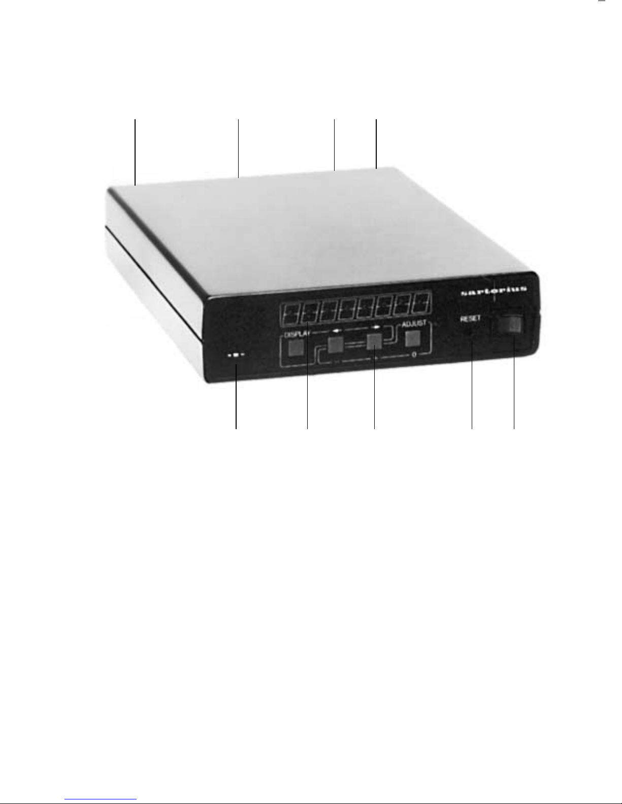
1 ON/OFF switch
Ein-/Aus-Schalter
2 reset button
reset-Taste
3 Pushbutton on the control panel
Tasten-Feld
4 led field
Anzeige-Feld
5 Analog output (BU3)
Analog-Ausgang (BU3)
3
6 Digital input from balance/scale and
Sartonet digital male connector (ST1)
Waagen-Digital-Eingang und SartonetDigital-Anschluß (ST1)
7 Sartonet digital female connector (BU2)
Sartonet-Digital Anschluß (BU2)
8 Plug receptacle
Netz-Stecker-Buchse
9 Voltage selector and fuse
Spannungs-Wähler und Sicherung
6789
543 21
Page 4

4
Page 5

Contents
Page
Equipment Supplied 6
Description of the Functions 6
Cabling Options 8
Converter Settings 13
Examples of Device Configurations 18
Cabling Diagram for Connecting
623301 to YDA 01 Z 24
Care and Maintenance 25
5
Page 6

Equipment Supplied/
Description of the Functions
Equipment Supplied
– Converter YDA 01 Z
– Power cord
– Standard cable “MP8” for connecting MP7, MP7-2
or MP8 balances/scales to YDA 01 Z
– V 24 cable for connecting MC1 balances/scales
to YDA 01 Z
Description of the Functions
Digital/analog converter YDA 01 Z is designed to
convert digital signals into analog voltages or loop
currents. Such an analog signal is available with two
different voltages and three different loop currents
at a 5-in round socket (similar to a DIN stereo jack).
The lower rating of the two voltages ranges from
+1 volt to –1 V.
The higher voltage ranges from +10 V to –10 volts.
The current interface can be adjusted to the following
loop currents:
a) 4– 20 mA
b) 0– 10 mA
c) 0– 20 mA
Setting a) complies with ISA S50.1, Standard
Class U, with the following specifications:
Load resistance: 300– 800 Ω
Supply voltage: 23– 30 V
Internal resistance: 600 Ω
Intrinsic safety: 250 Ω
6
Page 7

Digital input signals can be supplied to the converter via
the V24/RS 232 interface.
The converter enables the following devices to be
connected to analog processing systems (such as a Y/t
recorder):
a) Sartorius balance/scale with an MP7, MP7-2
or MP8 microprocessor
b) Sartonet bus
c) Device with a V24/RS 232 interface
It converts each digital value comprising 3 decades into
analog voltage or loop current.
The position of these 3 decades can be selected in a
range of 8 decades maximum.
The 3 particular decades selected are then indicated by
the corresponding LEDs on the control panel.
In addition, the converter will provide one of the
following reference voltages when you press the
appropriate pushbutton:
a) +1 volt and +10 volts (+ pushbutton)
b) –1 volt and –10 volts (– pushbutton)
c) 0 volts (0 pushbutton)
7
Page 8
Cabling Options
Device Combinations
MP7/MP7-2, MP8, MC1 balance/scale interfaced with an analog system via YDA 01 Z
Sartonet bus networked with an analog system via YDA 01 Z
etc.
8
Page 9
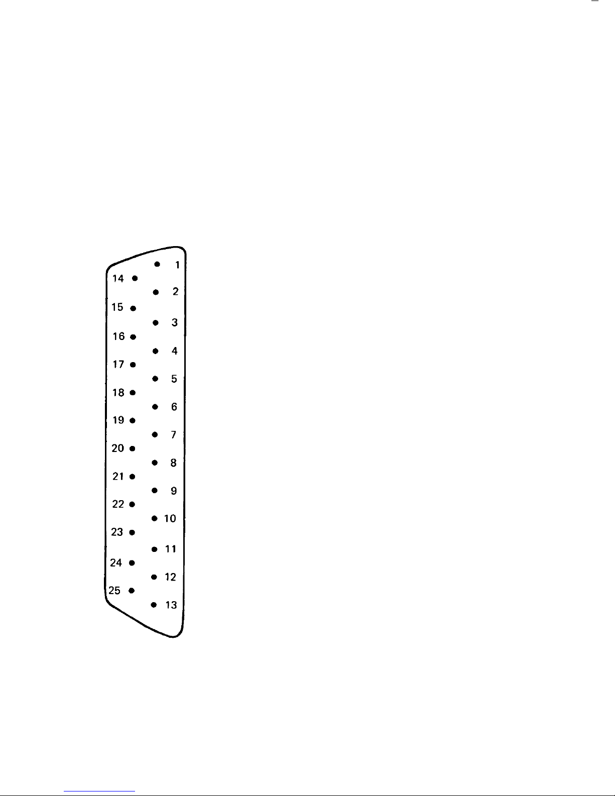
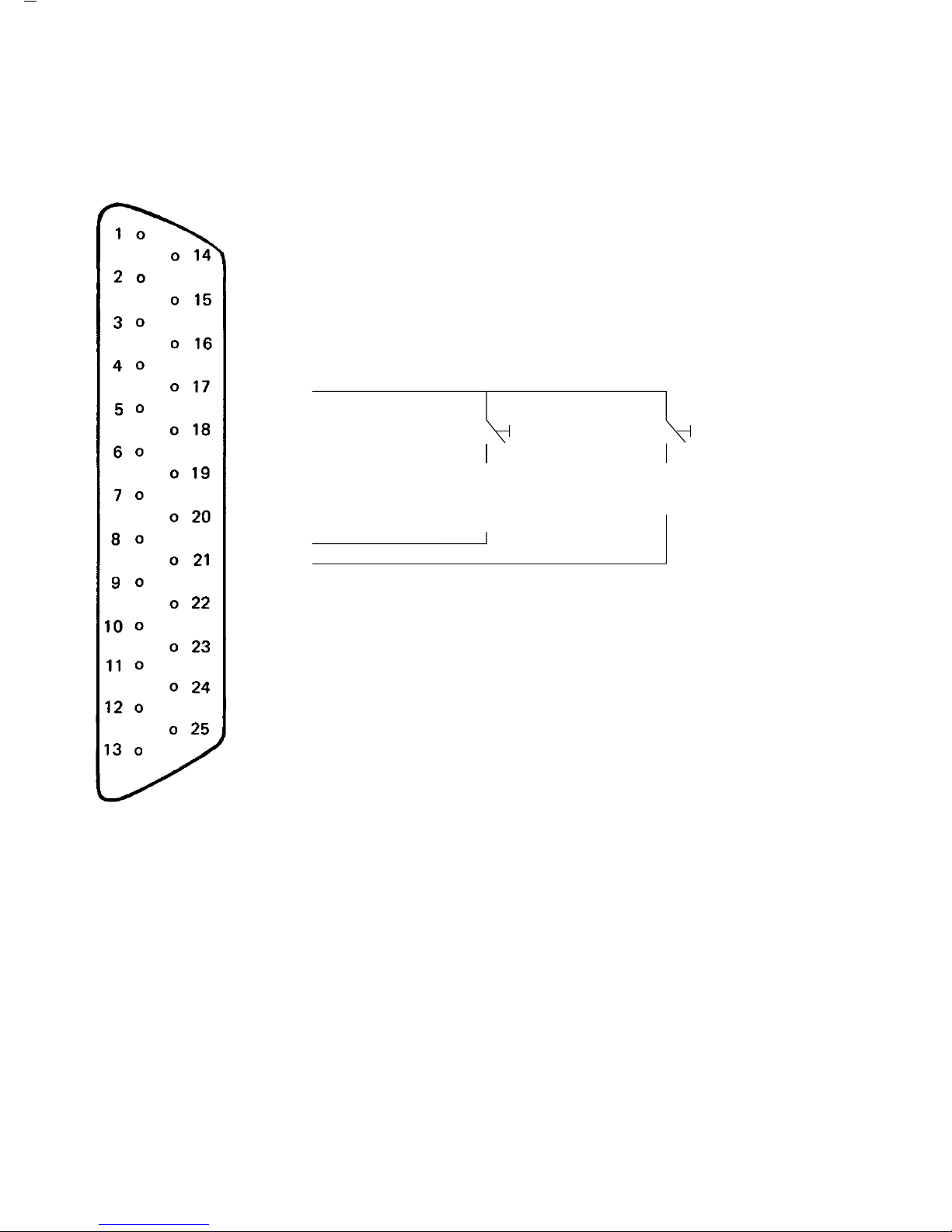
Cable and Pin Assignment
The location of the male and female connectors is indicated in the general view
of the converter and in a schematic of the printed circuit board (page 14).
The data available at male connector 1 (ST 1) are exactly the same as those available
at female connector 2 (BU 2).
Pin Assignment for ST 1:
1 Protective ground/signal ground (for Sartonet)
2 Data output (TxD)
3 Data input (RxD)
4 External ground
5 CTS input (Clear to Send)
6 Connected
7 Connected
8 Connected
9
10
11
12 Connected
13 Connected
14 Internal ground
15 Connected
16 Connected
17 Connected
18 Connected
19 Connected
20 DTR output (Data Terminal Ready)
21 Connected
22 Sartonet 1
23 Sartonet 2
24
25
9
Page 10
Pin Assignment for BU 2:
1 Protective ground/signal ground (for Sartonet)
2 Data output (TxD)
3 Data input (RxD)
4 External ground
5 CTS input (Clear to Send)
6 Connected
7 Connected
8
●
9
10
11
12 Connected Print key Tare
13 Connected (for ext. print control
14 Internal ground command only)
15
16
17 Connected
18 Connected
19 Connected
20 DTR output (Data Terminal Ready)
21 Connected
22 Sartonet 1
23 Sartonet 2
24
25 Connected
10
Page 11
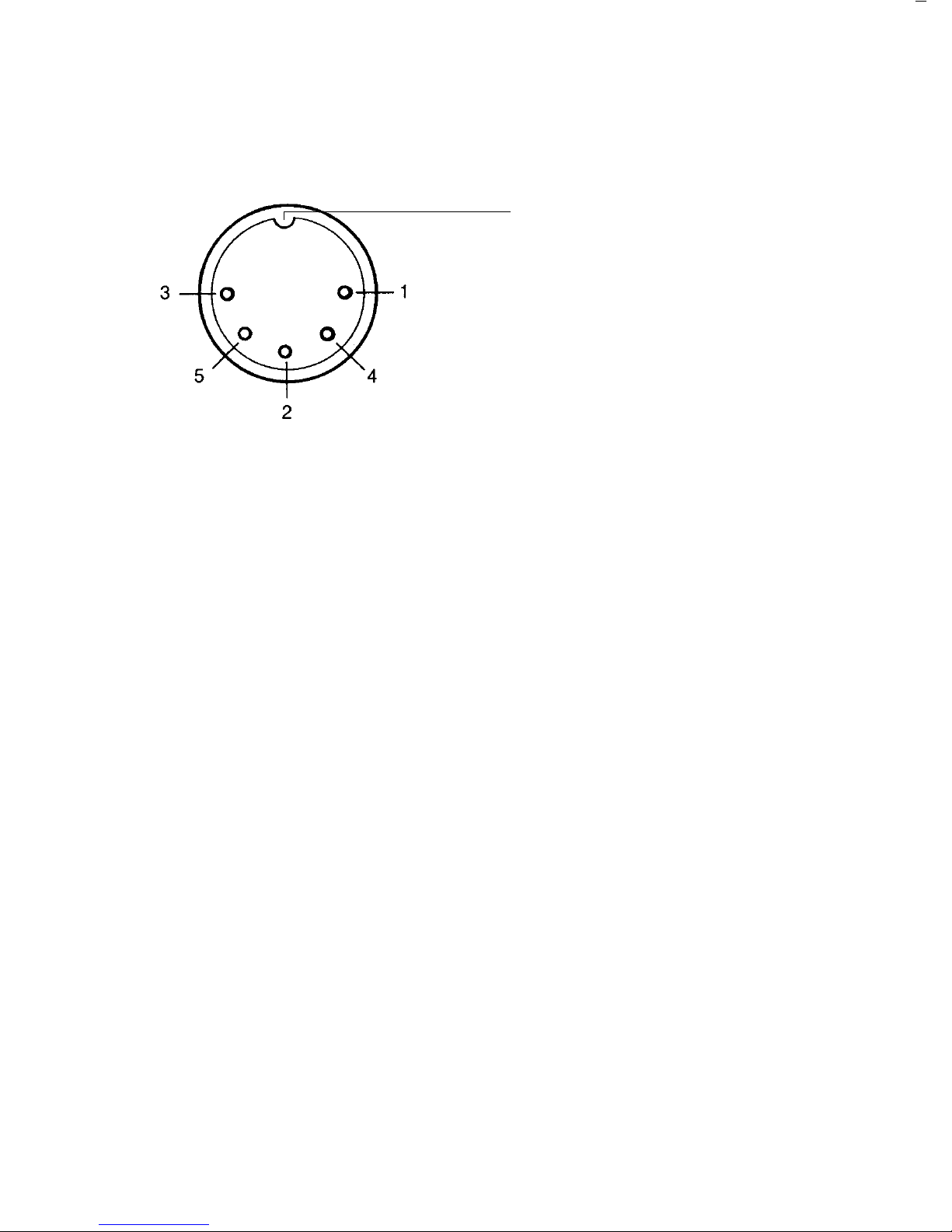
Pin Assignment for Socket BU 3 (Analog Data Output):
Chassis ground
Pin 1 +/–10 V (analog)
Pin 2 Signal ground
Pin 3 +/–1 V (analog)
Pin 4 Current output (–)
Pin 5 Current output (+)
Front view
Voltage ranges: Loop current ranges:
4– 20 mA
0...+/–10 volts, +/– 20 mV, I max. = 0.5 mA 0 –10 mA
0...+/–1 volt, +/– 2 mV, I max. = 3 mA 0 –20 mA
11
Page 12
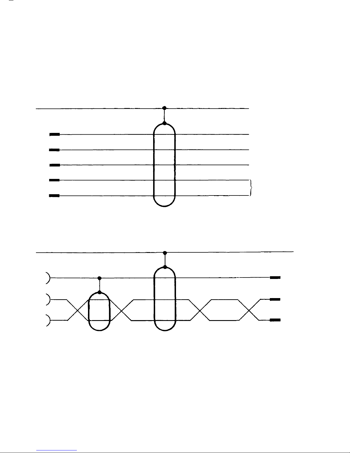
Pin Assignment of the Connecting Cable for the D/A Converter → Y/t Recorder
D/A converter Y/t recorder or similar device
5-terminal socket Matching plug
Frame ground
Shield
Plug end
1 +/–10 volts
2 Ground
3 +/–1 volt
4 Current loop
4– 20 mA
5
0– 10 mA
0– 20 mA
Sartonet connecting cable:
25-pin female Cannon connector 25-pin male Cannon connector
Frame ground Shield
1
Shield
1
22 22
23 23
Twisted pair
Type of cable: data transfer line/black (twisted pair)
12
Page 13
Converter Settings
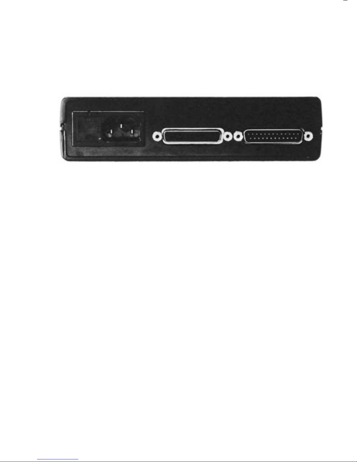
Adjusting the Operating Voltage
Rear view of the converter:
The small arrow points to the actual setting of the voltage selector.
The operating voltage has been factory-set to 220 V.
How to change the voltage setting:
Adjust the voltage selector (1) to your local line voltage. Write the new voltage setting on the
manufacturer’s label on the rear panel of the converter. Whenever you change the operating
voltage to 100/120 V, make sure to exchange the T 80 mA fuse (1) for the T 160 mA fuse
that comes with the converter.
This fuse, along with the voltage selector, is plugged into the rear panel
of the converter.
100/120 V – T 160 mA
220/240 V – T 80 mA
At the point of use, plug the power cord into a properly installed wall outlet.
If you use a wall outlet that does not have a protective grounding conductor, make sure to
ground the balance.
13
Page 14
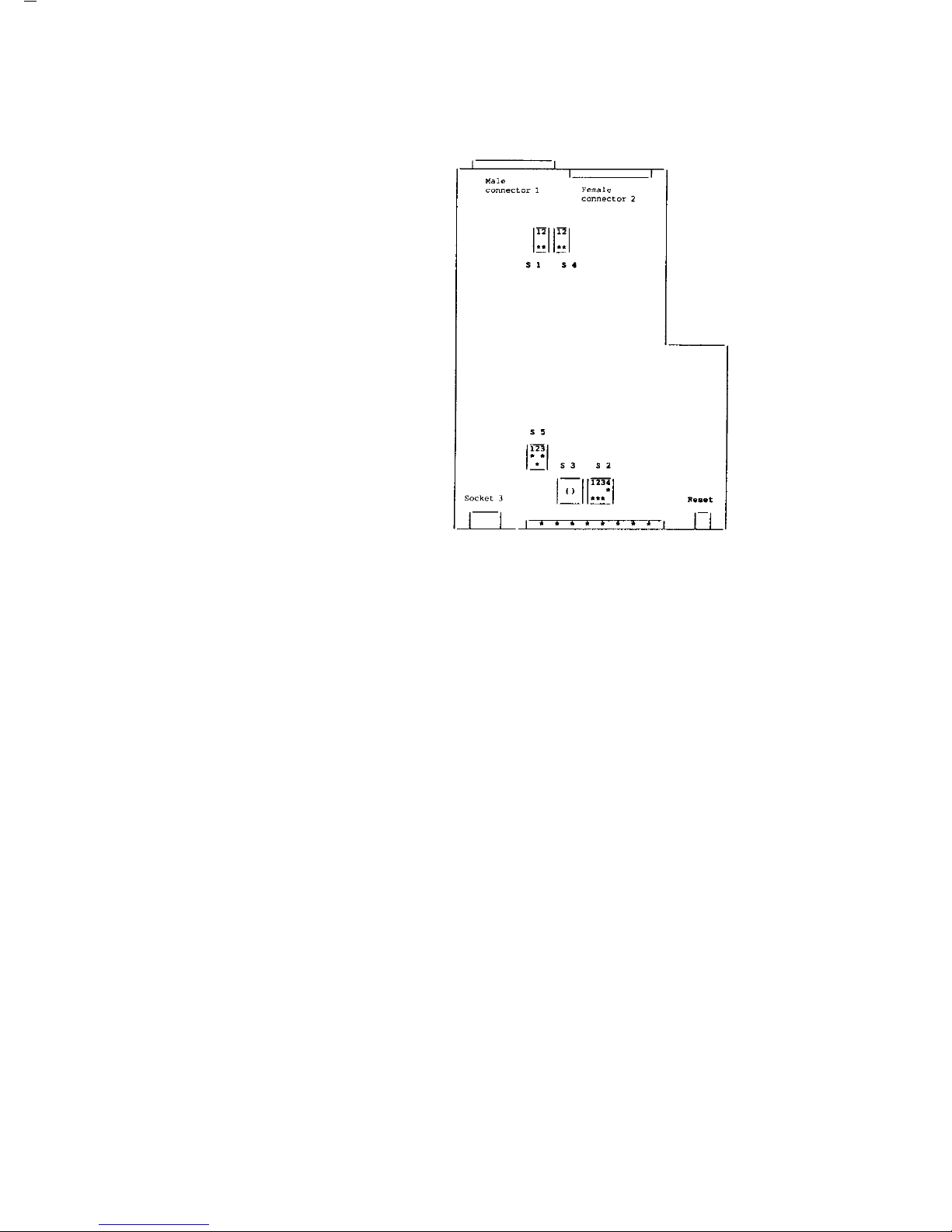
Description of the Switches
Location of the Switches on the
Printed Circuit (PC) Board
14
Page 15
Switch Settings
ON Switch OFF
External PRINT command S1.1 Automatic PRINT command
MP7, MP7-2 S1.2 MP8/MC1
Control mode S2.1 MP mode (MP7/MP7-2/MP8)
Even parity check (V 24) S2.2 Odd parity check (V 24)
Addresses 16...31 (Sartonet) Addresses 0...15 (Sartonet)
No parity check (V 24) S2.3 Parity check (V 24)
4,800 baud (Sartonet) 9,600 baud (Sartonet)
V24/RS 232 mode (software) S2.4 Sartonet mode (software)
V24/RS 232 mode Switch Sartonet mode
150 baud – 7 bits S3– 0 Address 0 or 16
300 baud – 7 bits S3– 1 Address 1 or 17
600 baud – 7 bits S3– 2 Address 2 or 18
1,200 baud – 7 bits S3– 3 Address 3 or 19
2,400 baud – 7 bits S3– 4 Address 4 or 20
4,800 baud – 7 bits S3– 5 Address 5 or 21
9,600 baud – 7 bits S3– 6 Address 6 or 22
9,600 baud – 7 bits S3– 7 Address 7 or 23
150 baud – 8 bits S3– 8 Address 8 or 24
300 baud – 8 bits S3– 9 Address 9 or 25
600 baud – 8 bits S3– A Address 10 or 26
1,200 baud – 8 bits S3– B Address 11 or 27
2,400 baud – 8 bits S3– C Address 12 or 28
4,800 baud – 8 bits S3– D Address 13 or 29
9,600 baud – 8 bits S3– E Address 14 or 30
9,600 baud – 8 bits S3– F Address 15 or 31
V24/RS 232 mode Switch Sartonet mode
off S4.1 on
on S4.2 off
Switch Operating mode
4– 20 mA 0– 10 mA 0– 20 mA
S5.1 off on on
S5.2 off on off
S5.3 off off on
15
Page 16
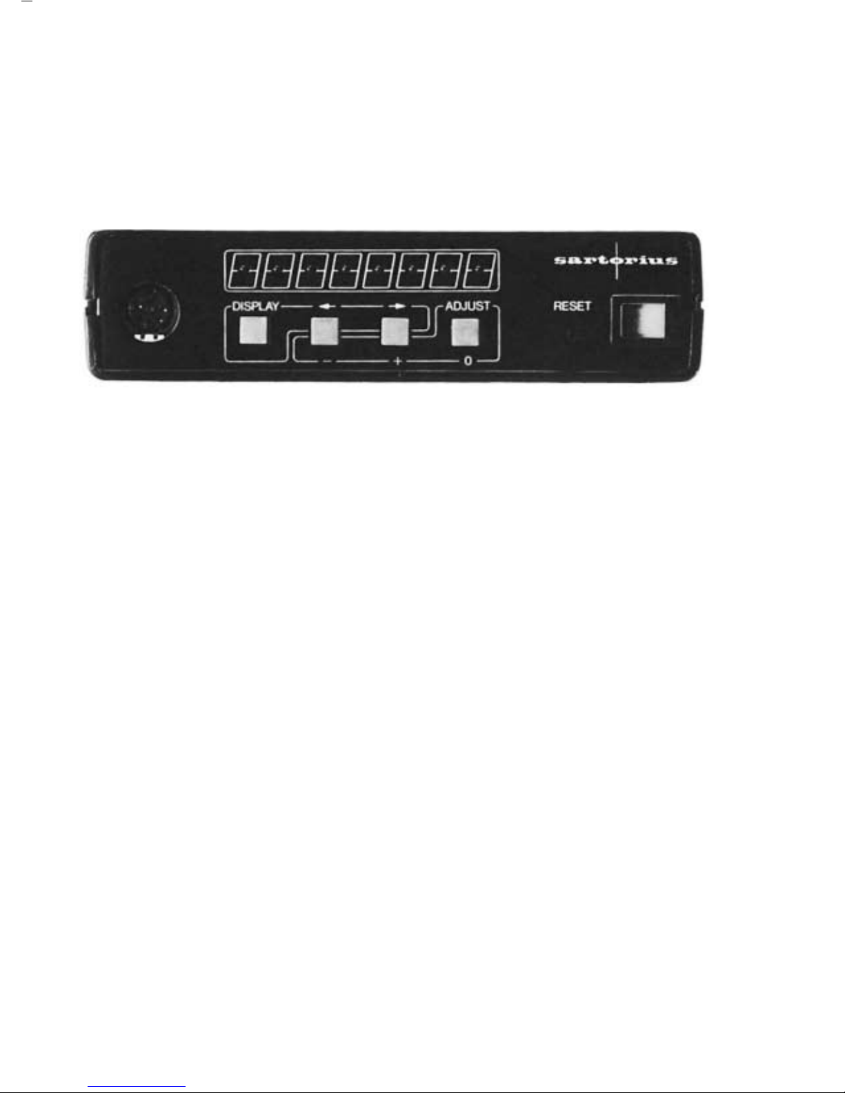
Settings on the Front Panel of the Converter
Front view of the converter:
Description of the pushbuttons:
“0” pushbutton: When you push this button, a reference voltage of 0 is generated at
pins 1 and 3 of the 5-pin round socket.
“+” pushbutton: Press this button to have a reference voltage of +10 volts generated
at pin 1 and +1 volt at pin 3 of the 5-pin round socket.
“–” pushbutton: Press this button to have a reference voltage of –10 volts generated
at pin 1 and –1 volt at pin 3 of the 5-pin round socket.
“DISPLAy” Push this button to initiate selection of the decade range.
pushbutton: The decade range consists of 3 decades which can be shifted
anywhere within the converter’s maximum range of 8 decades.
Once the “DISPLAY” pushbutton is pressed, the LEDs will
flash for about 3 seconds. If you press the “+” or “–” pushbutton
during this time, the next higher or lower decade level will be
automatically selected each second. To terminate the selection
procedure, release the “+” or “–” button.
The decade range selected is read into a non-volatile
memory so that it will remained stored no matter if you switch off the
converter.
“RESET” button: Press this button to have the YDA 01 Z converter enter
the “POWER ON” operating state (corresponds to the power
up routine).
16
Page 17

Loop currents available at the loop current interface:
Operating mode Pushbutton
4– 20 mA “–” = 4 mA ≅ – 10 V
“0”= 12 mA ≅ 0 V
}
at the voltage output
“+”= 20 mA ≅ +10 V
0– 10 mA “–” = 0 mA ≅ – 10 V
“0”= 5 mA ≅ 0 V
“+”= 10 mA ≅ +10 V
0– 20 mA “–” = 0 mA ≅ – 10 V
“0”= 10 mA ≅ 0 V
“+”= 20 mA ≅ +10 V
The current and voltage outputs are independent of each other and can be used
simultaneously.
Diagram for Selecting the Decade Range
Decade
selection
Options
for selecting the decade
range for a weight readout
consisting of a total
of 8 decades
17
87 654321
7
6
5
4
3
2
1
0
Page 18

Examples of Device Configurations
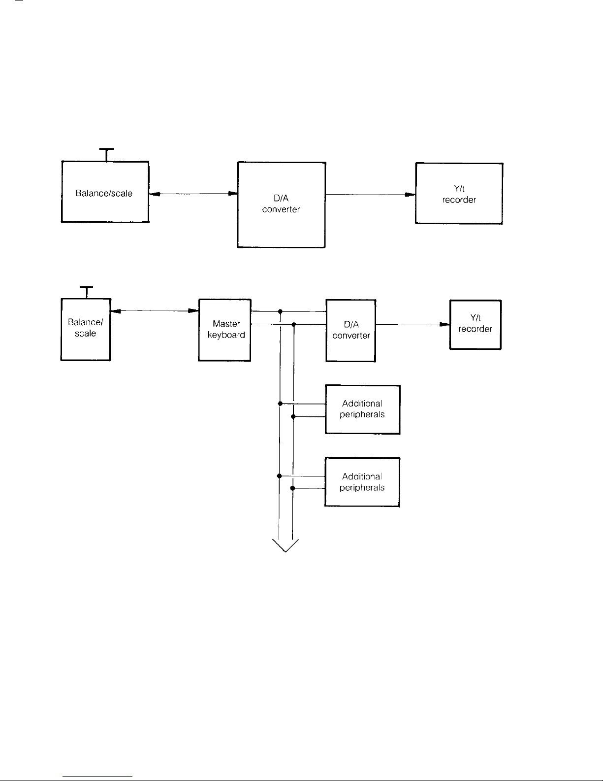
Digital/Analog Converter Linked to MP7 or MP7-2 Balances
Basic cabling diagram:
Data transfer between MP7/MP7-2 balances and the D/A converter is asynchronous in the
V24 operating mode.
Data transfer rate: 1,200 baud (bits per second)
Data transfer format: 1 start bit
7 data bits
1 parity bit
(odd parity)
1 stop bit
Data transfer code: ASCII = A = American
S = Standard
C = Code for
I = Information
I = Interchange
Basic Settings of the D/A Converter for MP7/MP7-2 Balances
S1.1 OFF Automatic print command
S1.2 ON MP7, MP7-2
S2.1 OFF MP mode (for MP7, MP7-2, MP8)
S2.2 –––– No function assigned
S2.3 –––– No function assigned
S2.4 ON V24/RS 232 mode (software)
S3.– –––– No function assigned
S4.1 OFF
S4.2 ON
}
V24/RS 232 mode (hardware)
18
MP7
BU3
Y/t
recorder
ST1
Digital/
analog
converter
BU2
Page 19

Important Note
Data can be transferred only if one device operates in the automatic PRINT mode
and the other in the external PRINT mode. The device operating in the automatic PRINT mode
independently generates the PRINT signal.
Make sure that only one device is set for the automatic PRINT mode at a time.
If you wish to have the balance continuously transmit weight changes, access the menu of the
balance operating program and select the code for data output without stability control (SK).
For MP7 series balances, adjust the settings
of the coding plug in the balance as shown
in the diagram on the right:
Digital/Analog Converter Linked to MP8/MC1 Balances and Scales
Basic cabling diagram:
Data are transferred between the balance or scale and the D/A converter in the full duplex
mode.
Data can be transferred only if one device operates in the automatic PRINT mode and the
other in the external PRINT mode. The device operating in the automatic PRINT mode
independently generates the PRINT signal.
Make sure that only one device is set for the automatic PRINT mode at a time.
19
Balance/
scale
BU3
Y/t
recorder
ST1
Digital/
analog
converter
BU2
Page 20

It is practical to set the balance or scale to the automatic print (auto PRINT) mode since in this
mode the print command from the converter does not have to be confirmed and the balance
will not generate an acoustic signal in response to each command.
Data transfer between the balance/scale and converter is only possible if they are both set
for same parameters as indicated below:
– Character length (7 or 8 bits)
– Parity check (yes/no/even/odd)
– Baud rates (150/300/600/1,200/2,400/4,800/9,600)
Basic Settings of the D/A Converter for MP8/MC1 Balances and Scales
S1.1 ON Balance/scale set to auto PRINT
S1.1 OFF Balance/scale set to external PRINT
S1.2 OFF MP8/MC1
S2.1 OFF MP mode (for MP7, MP7-2, MP8)
S2.2 OFF Odd parity check
S2.2 ON Even parity check
S2.3 OFF Parity check
S2.3 ON No parity check
S2.4 ON V24/RS 232 mode (software)
S3.– 0– F Baud rate (corresponds to balance/scale baud rate)
S4.1 OFF
S4.2 ON
}
V24/RS 232 mode (hardware)
Special operating menu settings for MC1 balances/scales:
– Automatic output of parameters “off” – code 7 1 1
– Data output with ID code “off” (without ID code) – code 7 2 1
20
Page 21

Digital/Analog Converter in the Sartonet Bus Network
Basic cabling diagram:
The Sartonet bus links several devices to one
another by the appropriate interfaces. Each
online device has a
25-pin female connector and a 25-pin male
connector which are used in the Sartonet bus
architecture as a data input and a data
output, respectively.
Data are transferred within the Sartonet
system via these connectors. A special
system controller, called a master, controls
data transfer within the bus system. Looking
at the basic cabling diagram where the
online converter
(e.g.,YDA 01 Z) is located, you can see that there is an additional connector for hookup of
devices for expanded application capabilities. This allows it to be interfaced with MP/MP6,
MP7/MP7-2/MP8, BCD parallel and V24/RS 232 units, etc. In the Sartonet architecture,
the D/A converter is linked via the Sartonet bus to the master and other peripherals.
Data are transferred serially in an asynchronous half-duplex operating mode at a baud rate
of 4,800 or 9,600 bits/sec.
Information is exchanged by a character-oriented control process. The length of a data word
is 10 bits/word.
The information is transferred in ASCII code with 7 data, start, parity and stop bits.
There are two types of information:
– data
– control sequences (ESCAPE sequences)
The data block can have an MP7, MP7-2 or MP8 format.
21
Page 22

Basic Settings of the D/A Converter for Sartonet
S1.1 ON Balance set to external PRINT
S1.2 OFF MP8
S2.1 OFF MP mode (for MP7, MP7-2, MP8)
S2.2 OFF Addresses 0…15
S2.2 ON Addresses 16…31
S2.3 OFF 9,600 baud
S2.3 ON 4,800 baud
S2.4 OFF Sartonet mode (software)
S3.– 0– F Address (corresponding to the balance)
S4.1 ON
S4.2 OFF
}
Sartonet mode (hardware)
Note on the Sartonet Operating Mode of the D/A Converter
The control sequences previously mentioned for remote control of the converter can only
be transmitted and received via Sartonet. That means a device for controlling the Sartonet
is needed for remote control of the converter.
Such a device can be a computer with a sufficiently high baud rate, such as a process
computer, which you can connect via a special converter to adapt the signal level.
Since the control (ESCAPE) sequences and their use including the timing necessary for the
Sartonet system are complex, these are described in detail in our “Sartonet Manual for
Interfaces and Peripherals” which is available on request.
22
Page 23

Digital/Analog Converter as a Control Converter in the Sartonet Bus Network
Basic cabling diagram:
In the Sartonet system, the D/A converter can control the particular equipment you need
for your application (such as a motor, analog display, Y/t recorder, etc.).
With a digital signal, the master can generate analog voltages (–10 volts to +10 volts)
or analog current at the output of the D/A converter. The data must be coded according
to the ASCII standard.
For details, please refer to the “Sartonet Manual for Interfaces and Peripherals.”
Basic Settings of the D/A Converter for the Sartonet Control Mode
S1.1 ON Balance/scale set to external PRINT
S1.2 OFF MP8
S2.1 ON Control mode
S2.2 OFF Addresses 0…15
S2.2 ON Addresses 16…31
S2.3 OFF 9,600 baud
S2.3 ON 4,800 baud
S2.4 OFF Sartonet mode (software)
S3.– 0– F Address (corresponding to the balance/scale)
S4.1 ON
S4.2 OFF
}
Sartonet mode (hardware)
23
Page 24

Cabling Diagram for Connecting 623301toYDA 01Z
Pin assignment:
Converter YDA 01 Z Recorder 623301
3-pin round plug 3-pin round plug
Shield
2 Protective ground 1
3 Data output 3
2
24
Page 25

Care and Maintenance
Cleaning
Before cleaning the converter, unplug it from the wall
outlet.
Please do no use any aggressive cleaning agents
(solvents or similar agents). Instead, use a piece of cloth
wet with a mild detergent.
Make sure that no liquid enters the converter housing.
After cleaning, wipe down the converter with a soft,
dry piece of cloth.
Safety Inspection
If there is any indication that safe operation of the
converter is no longer warranted, turn off the power and
unplug it from AC power. Lock it in a secure place to
ensure that it cannot be used for the time being.
In this case, notify your nearest Sartorius Service Center
or the International Service Support Department in
Goettingen, Germany. Only service technicians who
have access to the required maintenance manuals are
allowed to perform maintenance and repairwork on the
equipment.
We recommend the converter be inspected according
to the following checklist by a qualified Sartorius service
technician:
– Insulation resistance >2 megohms measured with
a constand voltage of at least 500 V at a 500 kohm
load
– Equivalent leakage current <0.75 mA measured by
a properly calibrated multimeter
25
Page 26

The duration and number of measurements should be
determined by a qualified Sartorius service technician
according to the particular ambient and operational
conditions. However, such inspections should be done
at least once a year.
Safety Certificate
Pursuant to the German Directive for the
Implementation of Regulations for Prevention of
Accidents “Elektrische Anlagen und Betriebsmittel
(VBG 4)” [Electrical Installations and Equipment] of
April 1986, in conjunction with Article 10 of the Low
Voltage Directive 73/23/EEC issued on February
19, 1973, by the European Community, it is hereby
certified that the equipment delivered,
“Digital/Analog Converter YDA 01 Z” is
manufactured and tested in compliance with the
following DIN/VDE regulations
DIN IEC 348/VDE 0411
Safety requirements for electronic measuring
apparatus
DIN IEC 380/VDE 0806
Safety of electrically energized office machines
DIN IEC 601/VDE 0750
Safety of medical electrical equipment
When you use electrical equipment in installations
and under ambient conditions requiring higher safety
standards, you must comply with the provisions as
specified in the applicable regulations for installation
in your country.
The electrical and electronic components used in
the converter are rated at least Class KSF according
to DIN 40040.
26
Page 27

Inhalt
Seite
Lieferumfang 28
Funktionsbeschreibung 28
Anschlußmöglichkeit 30
Einstellung des Wandlers 35
Beispiel-Konfigurationen 40
Verbindungs-Kabel zum Anschluß
von 623301 an YDA 01 Z 46
Pflege und Wartung 47
27
Page 28

Lieferumfang/
Funktionsbeschreibung
Lieferumfang
– Wandler YDA 01 Z
– Netz-Kabel
– Standard-Kabel »MP8« zum Anschluß von MP7,
MP7-2 bzw. MP8 an YDA 01 Z
– V 24-Kabel zum Anschluß von MC1-Waagen
an YDA 01 Z
Funktionsbeschreibung
Die Aufgabe des Digital/Analog-Wandlers
YDA 01 Z ist es, digitale Informationen in analoge
Spannungen bzw. Ströme umzusetzen. Dieser
Analogwert wird an einer 5poligen Rund-Buchse
(ähnlich einer Stereo-Buchse nach DIN) mit zwei
unterschiedlichen Spannungen und drei verschiedenen
Schleifenströmen zur Verfügung gestellt.
Die kleinere Spannung bewegt sich in einem Bereich
von +1 Volt bis –1 Volt.
Die größere Spannung bewegt sich in einem Bereich
von +10 Volt bis –10 Volt.
Die Stromschnittstelle ist einstellbar auf die
Schleifenströme:
a) 4– 20 mA
b) 0– 10 mA
c) 0– 20 mA
Dabei entspricht die Einstellung a) dem
ISA S50.1 Standard Klasse U:
Lastwiderstand: 300– 800 Ω
Versorgungsspannung: 23– 30 V
Quellenwiderstand: 600 Ω
Eigensicherheit: 250 Ω
28
Page 29

Die digitale Eingangs-Information kann über
V24/RS 232 dem Wandler zur Verfügung gestellt
werden.
Der Wandler ermöglicht den Anschluß folgender
Geräte an Analog-Werte verarbeitende Systeme
(z.B.: Y/t-Schreiber):
a) Sartorius-Waage mit MP7, MP7-2 oder MP8
b) Sartonet Bus
c) Gerät mit V24/RS 232-Datenausgang
Es wird jeweils ein 3 Dekaden großer Digitalwert in
analoge Spannung bzw. Schleifenstrom umgesetzt.
Die Position dieser 3 Dekaden kann in einem Bereich
von max. 8 Dekaden selektiert werden.
Die 3 ausgewählten Dekaden werden am Wandler
durch Leuchtdioden gekennzeichnet.
Weiterhin stellt der Wandler auf Tastendruck
folgende Referenz-Spannungen zur Verfügung:
a) +1 Volt und +10 Volt (Taste +)
b) –1 Volt und – 10 Volt (Taste –)
c) 0 Volt (Taste 0)
29
Page 30

Anschlußmöglichkeiten
Gerätekombinationen
Waage mit Datenschnittstelle MP7/MP7-2, MP8 und MC1 über YDA 01 Z
an ein Analog-System:
Sartonet-Bus über YDA 01 Z an ein Analog-System:
usw.
30
Page 31

Kabel- und Steckerbelegung
Pinbelegung der Stecker und Buchsen des Wandlers
Die Lage der Stecker und Buchsen ist aus der Gesamtansicht und der Platinen-Skizze
(Seite 36) ersichtlich.
Die am Stecker 1 (ST 1) anstehenden Daten stehen unverändert auch an Buchse 2
(BU 2) an.
Pinbelegung ST 1:
1 Schutzerde/galv. Masse (b. Sartonet)
2 Datenausgang (TxD)
3 Dateneingang (RxD)
4 Masse ext.
5 Clear to Send – Eingang (CTS)
6 belegt
7 belegt
8 belegt
9
10
11
12 belegt
13 belegt
14 Masse int.
15 belegt
16 belegt
17 belegt
18 belegt
19 belegt
20 Data Terminal Ready – Ausgang (DTR)
21 belegt
22 Sartonet 1
23 Sartonet 2
24
25
31
Page 32

Pinbelegung BU 2:
1 Schutzerde/galv. Masse (b. Sartonet)
2 Datenausgang (TxD)
3 Dateneingang (RxD)
4 Masse extern
5 Clear to Send – Eingang (CTS)
6 belegt
7 belegt
8
●
9
10
11
12 belegt Print-Taster Tara13 belegt (nur bei Taster
14 Masse intern Einzel-Print)
15
16
17 belegt
18 belegt
19 belegt
20 Data Terminal Ready – Ausgang (DTR)
21 belegt
22 Sartonet 1
23 Sartonet 2
24
25 belegt
32
Page 33

Pin-Belegung BU 3 (Datenausgang analog):
Gehäusemasse
Pin 1 +/–10 Volt (Analog)
Pin 2 Signal-Masse
Pin 3 +/–1 V (Analog)
Pin 4 Stromausgang –
Pin 5 Stromausgang +
Gerät von vorne
Spannungsbereich: Strombereich:
4– 20 mA
0...+/–10 Volt, +/– 20 mV, I max. = 0,5 mA 0 –10 mA
0...+/–1 Volt, +/– 2 mV, I max. = 3 mA 0 –20 mA
33
Page 34

Belegung des Verbindungs-Kabels D/A-Wandler → Y/t-Schreiber
D/A-Wandler Y/t-Schreiber o.ä.
5polige Buchse entspr. Anschluß
Gehäusemasse
Schirm
Steckerseite
1 +/–10 Volt
2 Masse
3 +/–1 Volt
4
Stromschleife
4– 20 mA
5
0– 10 mA
0– 20 mA
Sartonet-Verbindungs-Kabel:
25poliger Cannon-Buchse 25poliger Cannon-Stecker
Gehäusemasse Schirm
1
Schirm
1
22 22
23 23
Paarweise verdrillt
Kabeltype Datenübertragungs-Leitung/schwarz (twisted pair)
34
Page 35

Einstellung des Wandlers
Einstellung der Betriebs-Spannung
Rückansicht des Wandlers:
Die Pfeilmarkierung zeigt auf dem Spannungs-Wähler die eingestellte Spannung an.
Der Wandler ist eingestellt auf 220 Volt.
Anpassen an andere Spannung:
Stellen Sie den Spannungswähler (1) auf den Wert der örtlichen Spannung ein.
Vermerken Sie die geänderte Einstellung auf dem Typenschild auf der Rückseite
des Wandlers. Wechseln Sie bei einer Einstellungsänderung auf 100/120 V die
eingebaute Sicherung (1) T 80 mA gegen die mitgelieferte Sicherung T 160 mA aus.
Die Sicherung (1) ist zusammen mit dem Spannungswähler in der Rückseite des Wandlers
eingesteckt.
100/120 V – T 160 mA
220/240 V – T 80 mA
Schließen Sie den Wandler am Aufstellort mit
dem Netzkabel an eine vorschriftsmäßig installierte Steckdose an.
Bei Spannungsversorgung aus Netzen
ohne Schutzleiteranschluß ist die Waage zu erden.
35
Page 36

Beschreibung der Schalter
Lage der Schalter auf der Platine
36
Page 37

Einstellung der Schalter
ON Schalter OFF
Einzel-PRINT S1.1 Auto-PRINT
MP7, MP7-2 S1.2 MP8/MC1
Steuerungs-Mode S2.1 MP-Mode (MP7/MP7-2/MP8)
Even-Parity-Check (V 24) S2.2 Odd-Parity-Check (V 24)
Adr.16...31 (Sartonet) Adr. 0...15 (Sartonet)
No-Parity-Check (V 24) S2.3 Parity-Check (V 24)
4800 Baud (Sartonet) 9600 Baud (Sartonet)
V24/RS 232-Mode (Software) S2.4 Sartonet-Mode (Software)
V24/RS 232-Mode Schalter Sartonet-Mode
150 Baud – 7 Bits S3– 0 Adr. 0 bzw. 16
300 Baud – 7 Bits S3– 1 Adr. 1 bzw. 17
600 Baud – 7 Bits S3– 2 Adr. 2 bzw. 18
1,200 Baud – 7 Bits S3– 3 Adr. 3 bzw. 19
2,400 Baud – 7 Bits S3– 4 Adr. 4 bzw. 20
4,800 Baud – 7 Bits S3– 5 Adr. 5 bzw. 21
9,600 Baud – 7 Bits S3– 6 Adr. 6 bzw. 22
9,600 Baud – 7 Bits S3– 7 Adr. 7 bzw. 23
150 Baud – 8 Bits S3– 8 Adr. 8 bzw. 24
300 Baud – 8 Bits S3– 9 Adr. 9 bzw. 25
600 Baud – 8 Bits S3– A Adr. 10 bzw. 26
1,200 Baud – 8 Bits S3– B Adr. 11 bzw. 27
2,400 Baud – 8 Bits S3– C Adr. 12 bzw. 28
4,800 Baud – 8 Bits S3– D Adr. 13 bzw. 29
9,600 Baud – 8 Bits S3– E Adr. 14 bzw. 30
9,600 Baud – 8 Bits S3– F Adr. 15 bzw. 31
V24/RS 232-Mode Schalter Sartonet-Mode
off S4.1 on
on S4.2 off
Schalter Betriebsart
4– 20 mA 0– 10 mA 0– 20 mA
S5.1 off on on
S5.2 off on off
S5.3 off off on
37
Page 38

Einstellungen an der Front-Seite des Wandlers
Frontansicht des Wandlers:
Tastenbeschreibung:
»0«-Taste: Mit einem Druck auf diese Taste wird eine Referenz-Spannung
von 0 Volt auf Pin 1 und Pin 3 der 5poligen Rund-Buchse erzeugt.
»+«-Taste: Mit einem Druck auf diese Taste wird eine Referenz-Spannung von
+10 Volt auf Pin 1 und von +1 Volt auf Pin 3 der 5poligen RundBuchse erzeugt.
»–«-Taste: Mit einem Druck auf diese Taste wird eine Referenz-Spannung von
–10 Volt auf Pin 1 und von –1 Volt auf Pin 3 der 5poligen RundBuchse erzeugt.
»DISPLAY«-Taste: Mit einem Druck auf diese Taste wird die Einstellung des Dekaden-
Bereiches eingeleitet. Der Dekaden-Bereich besteht aus 3 Dekaden,
die sich beliebig über den maximalen Bereich der Wandlers von
8 Dekaden verschieben lassen.
Wird die »DISPLAY«-Taste gedrückt, so blinken die LED’s für
ca. 3 Sekunden. Wird in dieser Zeit die »+« (»–«)-Taste gedrückt,
so wird automatisch jede Sekunde die nächst höhere (niedrigere)
Dekaden-Stufe ausgewählt. Der Vorgang wird beendet, sobald die
Taste (+ oder –) losgelassen wird.
Die Dekaden-Einstellung wird in einem nichtflüchtigen Speicher
abgelegt, so daß sie nach Aus- und Ein-Schalten des Wandlers
präsent ist.
»RESET«-Taste: Mit einem Druck auf diese Taste wird der Wandler in den »POWER
ON«-Zustand versetzt. (Entspr. dem Einschalten.)
38
Page 39

Schleifenströme an der Stromschnittstelle:
Betriebsart Taste
4– 20 mA “–” = 4 mA ≅ – 10 V
“0”= 12 mA ≅ 0 V
}
am Spannungsausgang
“+”= 20 mA ≅ +10 V
0– 10 mA “–” = 0 mA ≅ – 10 V
“0”= 5 mA ≅ 0 V
“+”= 10 mA ≅ +10 V
0– 20 mA “–” = 0 mA ≅ – 10 V
“0”= 10 mA ≅ 0 V
“+”= 20 mA ≅ +10 V
Strom- und Spannungsausgang sind unabhängig voneinander und können gleichzeitig
benutzt werden.
Diagramm zur Dekaden-Bereichs-Einstellung
DekadenEinstellung
Mögliche Lage
des eingestellten
Dekaden-Bereiches im Bezug
auf ein 8 Dekaden
großes Wäge-Ergebnis
39
87 654321
7
6
5
4
3
2
1
0
Page 40

Beispiel-Konfigurationen
Digital/Analog-Wandler im Anschluß an MP7 bzw. MP7-2-Waagen
Skizze des prinzipiellen Anschlusses:
Die Datenübertragung zwischen MP7/MP7-2-Waagen und dem D/A-Wandler erfolgt im
asynchronen Betrieb. Die Daten werden im V24-Betriebsmode übertragen.
Daten-Übertragungs-Format: 1200 Baud (Bit je Sekunde)
Daten-Übertragungs-Format: 1 Start-Bit
7 Daten-Bit
1 Parity-Bit
(Odd-Parity)
1 Stop-Bit
Daten-Übertragungs-Code: ASCII = A = American
S = Standard
C = Code for
I = Information
I = Interchange
Grund-Einstellung des D/A-Wandlers für MP7/MP7-2
S1.1 OFF Auto-Print
S1.2 ON MP7, MP7-2
S2.1 OFF MP-Mode (für MP7, MP7-2, MP8)
S2.2 –––– ohne Bedeutung
S2.3 –––– ohne Bedeutung
S2.4 ON V24/RS 232-Mode (Software)
S3.– –––– ohne Bedeutung
S4.1 OFF
S4.2 ON
}
V24/RS 232-Mode (Hardware)
40
MP7
BU3
Y/t
Schreiber
ST1
Digital/
Analog
Wandler
BU2
Page 41

Achtung!
Die Daten-Übertragung kann nur stattfinden, wenn ein Gerät im Auto-PRINT-Mode arbeitet
und das andere im Einzel-PRINT-Mode.
Das Gerät, welches im Auto-PRINT-Mode arbeitet, erzeugt selbständig den PRINT-Impuls.
Es darf nie mehr als ein Gerät auf Auto-PRINT-Mode eingestellt sein.
Soll der D/A-Wandler die Gewichtsänderungen der Waage kontinuierlich ausgeben,
so muß die Waage auf Datenausgabe ohne Stillstands-Kontrolle (SK) eingestellt sein.
Dies wird z.B.: bei MP7-Waagen durch
Einstellen eines Kodier-Steckers in der
Waage entspr. der folgenden Skizze
erreicht:
Digital/Analog-Wandler im Anschluß an MP8/MC1-Waagen
Skizze des prinzipiellen Anschlusses:
Die Datenübertragung zwischen der Waage und dem D/A-Wandler erfolgt
im Vollduplex-Betrieb.
Eine Daten-Übertragung kann nur stattfinden, wenn ein Gerät im Auto-PRINT-Mode arbeitet
und das andere im Einzel-PRINT-Mode.
Das Gerät, welches im Auto-PRINT-Mode arbeitet, erzeugt selbständig den
PRINT-Impuls.
Es darf nie mehr als ein Gerät auf Auto-PRINT-Mode eingestellt sein.
41
Waage
BU3
Y/t
Schreiber
ST1
Digital/
Analog
Wandler
BU2
Page 42

Zweckmäßig ist, die Waage auf Auto-PRINT einzustellen, da hierbei eine Bestätigung des
PrinT-Befehls vom Wandler entfällt und die Waage nicht mit dem Piepton reagiert.
Um einen Betrieb zwischen Waage und Wandler zu ermöglichen,
müssen übereinstimmen:
– Zeichen-Länge (7 Bit o. 8 Bit)
– Parity-Check (Yes/No/Even/Odd)
– Übertragungs-Geschwindigkeiten (150/300/600/1200/2400/4800/9600)
Grund-Einstellung des D/A-Wandlers für MP8/MC1
S1.1 ON Waage auf Auto-PRINT
S1.1 OFF Waage auf Einzel-PRINT
S1.2 OFF MP8/MC1
S2.1 OFF MP-Mode (für MP7, MP7-2, MP8)
S2.2 OFF Odd-Parity-Check
S2.2 ON Even-Parity-Check
S2.3 OFF Parity-Check
S2.3 ON No-Parity-Check
S2.4 ON V24/RS 232-Mode (Software)
S3.– 0– F Baudrate (entspr. Waage)
S4.1 OFF
S4.2 ON
}
V24/RS 232-Mode (Hardware)
Spezielle Waagenbetriebsmenü-Einstellungen bei MC1-Waagen:
– automatische Ausgabe der Parameter »aus« – Code 7 1 1
– Kennzeichnung der Datenausgabe »aus« – Code 7 2 1
42
Page 43

Digital/Analog-Wandler im Sartonet-Bus
Skizze des prinzipiellen Anschlusses:
Das Sartonet-Bus verbindet mehrere
Geräte mit entsprechenden Schnittstellen
untereinander. Jedes angeschlossene
Gerät hat eine 25polige Buchse und
einen 25poligen Stecker, die im SartonetKonzept als Dateneingang bzw. als
Datenausgang benutzt werden. Über
diese Buchsen und Stecker wird der
Daten-Transfer im Sartonet-System realisiert.
Ein spezieller System-Controller regelt den
Daten-Transfer innerhalb des Bus-Systems.
Dieser System-Controller wird als Master
bezeichnet.
Auf der Peripherie-Seite des angeschlossenen Gerätes (z.B. YDA 01 Z) befindet sich ein
weiterer Anschluß für entsprechende Aufgaben. So gibt es Anpassungen an MP/MP6,
MP7/MP7-2/MP8, BCD-parallel, V24/RS 232, etc.
Im Sartonet-Konzept ist der D/A-Wandler über den Sartonet-Bus mit dem Master und
anderen Peripherie-Geräten verbunden. Die Datenübertragung erfolgt seriell
im asynchronen Halbduplex-Betrieb mit einer Baud-Rate von 4800 oder 9600 Bit/sek.
Der Informations-Austausch erfolgt mit Hilfe eines zeichen-orientierten Steuerungs-Verfahrens.
Die Länge eines Daten-Wortes ist auf 10 Bit/Wort festgelegt.
Die Information wird im ASCII-Code mit 7 Daten-, Start-, Parity- und Stop-Bits übertragen.
Es gibt zwei Informationstypen:
– Daten
– Kontroll-Sequenzen (ESCAPE-Sequenzen)
Der Daten-Block kann das MP7, MP7-2 oder MP8-Format besitzen.
43
Page 44

Grund-Einstellung des D/A-Wandlers für Sartonet
S1.1 ON Waage auf Einzel-PRINT
S1.2 OFF MP8
S2.1 OFF MP-Mode (für MP7, MP7-2, MP8)
S2.2 OFF Adr. 0…15
S2.2 ON Adr. 16…31
S2.3 OFF 9600 Baud
S2.3 ON 4800 Baud
S2.4 OFF Sartonet-Mode (Software)
S3.– 0– F Adresse (entspr. Waage)
S4.1 ON
S4.2 OFF
}
Sartonet-Mode (Hardware)
Anmerkung zum Sartonet-Betrieb des D/A-Wandlers
Die vorgenannten Kontroll-Sequenzen zur Fernsteuerung des Wandlers sind nur über Sartonet
send- und empfangbar. Das bedeutet, daß zur Fernsteuerung des Wandlers ein Sartonetkontrollierendes Gerät benötigt wird.
Hierzu können auch genügend schnelle Rechner, z.B. Prozeß-Rechner, benutzt werden,
die dann über einen speziellen Wandler zur Pegelanpassung angeschlossen werden.
Da die Kontroll-(ESCAPE-)Sequenzen und deren Anwendung und die für Sartonet
notwendige, zeitliche Steuerung komplex sind, steht eine ausführliche Beschreibung mit dem
»Sartonet-Handbuch für Schnittstellen und Peripherie« zur Verfügung.
44
Page 45

Digital/Analog-Wandler im Sartonet-Bus als Steuer-Wandler
Skizze des prinzipiellen Anschlusses:
Im Sartonet-Konzept kann der D/A-Wandler kundenspezifische Geräte (z.B. Motor,
Analog-Anzeige, Y/t-Schreiber) steuern.
Der Master kann mit einer digitalen Information eine analoge Spannung (–10 Volt bis
+10 Volt) oder einen analogen Strom am Ausgang des D/A-Wandlers erzeugen.
Die Daten müssen entsprechend der ASCII-Norm kodiert sein.
Einzelheiten sind dem »Sartonet-Handbuch für Schnittstellen und Peripherie«
zu entnehmen.
Grund-Einstellung des D/A-Wandlers für Sartonet-Steuer-Mode
S1.1 ON (Waage auf Einzel-PRINT)
S1.2 OFF MP8
S2.1 ON Steuerungs-Mode
S2.2 OFF Adr. 0…15
S2.2 ON Adr. 16…31
S2.3 OFF 9600 Baud
S2.3 ON 4800 Baud
S2.4 OFF Sartonet-Mode (Software)
S3.– 0– F Adresse (entspr. Waage)
S4.1 ON
S4.2 OFF
}
Sartonet-Mode (Hardware)
45
Page 46

Verbindungs-Kabel zum Anschluß
von 623301an YDA 01Z
Pinbelegung:
Wandler YDA 01 Z Schreiber 623301
3poliger Rundstecker 3polier Rundstecker
Schirm
2 Schutzerde 1
3 Data output 3
2
46
Page 47

Pflege und Wartung
Reinigung
Vor Reinigung des Gerätes trennen Sie die
Netzverbindung bitte vom Netz.
Benutzen Sie bitte keine aggressiven Reinigungsmittel
(Lösungsmittel o.ä.), sondern ein mit leichter Seifenlauge
angefeuchtetes Tuch.
Achten Sie darauf, daß keine Flüssigkeit in das Gerät
eindringt und reiben Sie mit einem trockenen, weichen
Tuch nach.
Sicherheitsüberprüfung
Erscheint Ihnen ein gefahrloser Betrieb nicht mehr
gewährleistet, so setzen Sie das Gerät durch Trennen
von der Netzspannung außer Betrieb und sichern Sie es
gegen weitere Benutzung.
Benachrichtigen Sie in diesem Fall den
Sartorius-Kundendienst.
Instandsetzungsmaßnahmen dürfen nur von Fachkräften
ausgeführt werden, die Zugang zu
den nötigen Instandsetzungsunterlagen
und -anweisungen haben.
Eine regelmäßige Überprüfung durch einen Fachmann
wird für folgende Punkte empfohlen:
– Isolationswiderstand >2 MOhm mit einer
Gleichspannung von mindestens 500 V bei
500 kOhm Last
– Ersatz-Ableitstrom <0.75 mA mit einem
bestimmungsgemäßen Meßgerät
47
Page 48

Zeitraum und Umfang der Messungen sollten
nach den Umgebungs- und Einsatzbedingungen durch
einen Fachmann vor Ort festgelegt werden, mindestens
jedoch einmal jährlich.
Sicherheitszertifikat
Gemäß der Durchführungsanweisung zur
Unfallverhütungsvorschrift »Elektrische Anlagen und
Betriebsmittel (VBG 4)« vom April 1986 in Verbindung
mit Artikel 10 der Niederspannungsrichtlinie
73/23/EWG der Europäischen Gemeinschaft vom
19.02.73
wird hiermit bestätigt, daß der gelieferte Gegenstand
»Digital/Analog-Wandler YDA 01 Z« nach den
DIN/VDE-Bestimmungen
DIN IEC 348/VDE 0411
Sicherheitsbestimmungen für elektronische Meßgeräte
DIN IEC 380/VDE 0806
Sicherheit elektrisch versorgter Büromaschinen
DIN IEC 601/VDE 0750
Sicherheit elektromedizinischer Geräte
gefertigt und geprüft ist.
Bei Verwendung elektrischer Betriebsmittel in Anlagen
und Umgebungsbedingungen mit erhöhten
Sicherheitsanforderungen sind die Auflagen gemäß
den zutreffenden Errichtungsbestimmungen zu
beachten.
Die in der Waage verwendeten elektrischen
Bauelemente sind nach DIN 40040 mindestens in die
Klasse KSF eingeordnet.
48
Page 49

49
Page 50

Page 51

Page 52

Sartorius AG
b 37070 Goettingen, Germany
p Weender Landstrasse 94–108, 37075 Goettingen, Germany
t (+49/551) 308-0, f (+49/551) 308-289
Internet: http://www.sartorius.com
Copyright by Sartorius AG, Goettingen, Germany.
All rights reserved. No part of this publication
may be reprinted or translated in any form or by any means
without the prior written permission of Sartorius AG.
The status of the information, specifications and
illustrations in this manual is indicated by the date
given below. Sartorius AG reserves the right to
make changes to the technology, features,
specifications and design of the equipment
without notice.
Status: September1998, Sartorius AG, Goettingen, Germany
Printed in Germany on paper that has been bleached without any use of chlorine
W1A343 · KT
Publication No.: WYD6021-a98083
 Loading...