

Page 1
Operating Manual
X3 Process Indicator PR 5410
Operating Manual
for PR 5410 Release: 1.30
Sartorius Mechatronics T&H GmbH, Meiendorfer Str. 205, 22145 Hamburg, Germany
Tel:+49.40.67960.303 Fax:+49.40.67960.383
9499 050 54102
Edition 2 01.02.2008
Page 2

Note
The information in this document is subject to change without notice and does not represent a commitment on the part of
Sartorius unless legally prescribed. This product should be operated only by trained and qualified personnel. Please include the
model, name, release number and all license numbers in all correspondence concerning this product.
Bitte beachten
Alle Angaben in diesem Dokument sind - soweit nicht gesetzlich vorgegeben - unverbindlich für SARTORIUS und stehen unter
Änderungsvorbehalt. Die Bedienung des Produktes darf nur von geschultem, fach- und sachkundigem Personal durchgeführt
werden. Bei Schriftwechsel über dieses Produkt bitte Typ, Bezeichnung und Versionsnummer sowie alle mit dem Produkt in
Zusammenhang stehenden Lizenznummern angeben.
Page 3

X3 Operating Manual Contents
Contents
1 Warnings and Safety Precautions...................................................................................................................................7
1.1 Intended Use ....................................................................................................................................................................7
1.2 Initial Inspection ..............................................................................................................................................................7
1.3 Before Commissioning ....................................................................................................................................................7
1.3.1 Installation 7
1.3.2 Opening the Instrument 7
1.3.3 Grounding and Shock Prevention PR 5410/00 8
1.3.4 Power Connection and Power Supply PR 5410/00 8
1.3.5 Failure and Excessive Stress 8
1.3.6 Important Note 8
2 Process Indicator ............................................................................................................................................................. 9
2.1 Overview of the Instrument............................................................................................................................................9
2.2 Housing ..........................................................................................................................................................................10
2.3 Display and Controls .....................................................................................................................................................11
2.3.1 Display 11
2.3.2 Front-Panel Keys 11
2.3.3 Selection Using the Navigation Keys (VNC) 12
2.3.4 Tool Tip (VNC) 12
2.3.5 System Messages during Input (VNC) 13
2.3.6 Overview of Accessories 14
2.3.7 Plug-in Cards 15
3 Installing the Instrument and Plug-in Cards ..............................................................................................................16
3.1 Mechanical Preparation.................................................................................................................................................16
3.2 Hardware Construction .................................................................................................................................................16
3.3 Main Board.....................................................................................................................................................................16
3.3.1 Network Port 17
3.3.2 Standard RS-232 Interface 17
3.3.3 Optocoupler Inputs 19
3.3.4 Optocoupler Outputs 20
3.4 Accessories......................................................................................................................................................................21
3.4.1 Installing Plug-in Cards 21
3.4.2 Cable Connection in the D-Sub Connector Mating Plug 22
3.4.3 PR 5510/02 Serial I/O 23
3.4.4 PR 5510/04 Serial I/O 24
3.4.5 PR 5510/07 Analog Input/Output Card 28
3.4.6 PR 5510/08 BCD Output (Open Emitter) 30
3.4.7 PR 5510/09 BCD Output (Open Collector) 33
3.4.8 PR 5510/12 6 Optocoupler Inputs / 12 Optocoupler Outputs 38
3.4.9 PR 1721/31 Profibus Interface 43
3.4.10 PR 1721/32 Interbus Interface 44
3.4.11 PR 1721/34 DeviceNet Interface 45
3.4.12 PR 1721/37 EtherNet/IP Schnittstelle 46
3.4.13 PR 5510/14 ModBus TCP Interface 47
3.5 Connecting Load Cells...................................................................................................................................................48
3.5.1 Connecting a Load Cell with 4-Wire Cable 48
3.5.2 Connecting PR 6221 Load Cells 48
3.5.3 Connecting up to 8 Load Cells (650 Ohms) Using 6-Wire Connecting Cable 49
3.5.4 Connecting Load Cells with External Supply 50
3.5.5 Connecting Load Cells via Intrinsically Safe Load Cell Interface PR 1626/60 51
3.5.6 Connecting Platforms (CAP...) 52
4 Commissioning ..............................................................................................................................................................53
4.1 Data Protection/Power Failure .....................................................................................................................................53
4.1.1 CAL Switch 53
4.2 Switching on the Instrument........................................................................................................................................54
Sartorius 3
Page 4

Contents X3 Operating Manual
4.2.1 Display Test 54
4.2.2 Front-Panel Key Test 54
4.2.3 Resetting the Instrument to the Factory Settings 54
4.2.4 Setting the Network Address Using Front-Panel Keys 55
4.2.5 Viewing the Network Address via Front-Panel Keys 55
4.2.6 Searching the Instrument in the Network Using 'IndicatorBrowser' 55
4.2.7 Loading New Software 56
4.3 Konfiguration and Calibration using Front Keys....................................................................................................... 57
4.3.1 Meaning of Front Keys 57
4.3.2 Entering Date and Time 57
4.3.3 Parameter Table 58
4.3.4 New Calibration using Front Keys 60
4.3.5 Subsequent Change of Deadload using Front Keys 61
4.3.6 View Calibration Data 61
4.3.7 View Calibration Data for Deadload and Maximum Load 62
4.3.8 PIN Code 62
4.4 Operation Using a PC ................................................................................................................................................... 63
4.4.1 Operation Using the VNC Program 63
4.4.2 Operation Using Internet Browser 64
4.4.3 INFO Function 65
4.4.4 Setup Function (VNC) 66
4.4.5 Setup Menu (VNC): Overview 66
4.4.6 Calibration Menu 67
4.5 Calibration...................................................................................................................................................................... 68
4.5.1 Displaying Calibration Data 68
4.5.2 Selecting the Calibration Mode 69
4.5.3 Determining the Maximum Capacity (Max) 70
4.5.4 Determining the Scale Interval 71
4.5.5 Determining the Dead Load 72
4.5.6 Calibration with Weight (by Load) 73
4.5.7 Calibration with mV/V Value 74
4.5.8 Calibration with Load Cell Data (“Smart Calibration“) 75
4.5.9 Subsequent Dead Load Correction 76
4.5.10 Linearization 76
4.5.11 Test Value Determination / Display 77
4.5.12 Finishing / Saving the Calibration 77
4.5.13 Parameter Input 78
4.6 Error Messages............................................................................................................................................................... 81
4.6.1 Measuring Circuit Error Messages 81
4.6.2 General Error Messages 81
4.7 Configuring General Parameters.................................................................................................................................. 82
4.7.1 Date and Time 82
4.7.2 Serial Ports 82
4.7.3 SMA Protocol 84
4.7.4 EW Protocol 84
4.7.5 Operating Parameters 85
4.7.6 Printing Parameters 86
4.7.7 Fieldbus Parameters 87
4.7.8 Network Parameters 88
4.8 Limit Values, Digital Inputs and Outputs ................................................................................................................... 89
4.8.1 Conditions for Limit Values and Digital Inputs, States for Outputs 89
4.8.2 Configuring Digital Inputs and Outputs 90
4.8.3 Configuring Outputs 90
4.8.4 Configuring Inputs 91
4.8.5 Configuring Limit Values 93
4.8.6 BCD Output 95
4.9 Analog Output............................................................................................................................................................... 96
4.9.1 Adapting the Analog Output 97
4.10 Alibi Memory .................................................................................................................................................................98
4.11 ConfigureIt Professional ............................................................................................................................................... 99
4 Sartorius
Page 5

X3 Operating Manual Contents
4.11.1 Installation 99
4.11.2 Program Start 101
4.11.3 Establish Communication to the Instrument 103
4.11.4 Transfer Dataset from Instrument to PC 104
4.11.5 Store Current Dataset on PC 104
4.11.6 Store Current Dataset or Selected Parameters in the Instrument 106
4.11.7 Reset the Instrument to Factory Default 106
4.11.8 Exporting a Dataset as Printable File 106
4.11.9 Operation of the Instrument via Browser (VNC) 107
4.11.10 Closing the Program 107
4.12 MODBUS / J-BUS Protocol ........................................................................................................................................ 108
4.12.1 Communication 108
4.12.2 Function 1 or 2: Reading n Bits 109
4.12.3 Function 3 or 4: Reading n Successive Words 109
4.12.4 Function 5: Writing a Bit 110
4.12.5 Function 6: Writing a Word 110
4.12.6 Function 8: Diagnosis 111
4.12.7 Function 15: Writing n Successive Bits 111
4.12.8 Function 16: Writing n Successive Words 112
4.12.9 MODBUS / J-BUS Error Messages 112
4.12.10 MODBUS / J-BUS Word Addresses 113
5 SMA Protocol...............................................................................................................................................................114
5.1 General......................................................................................................................................................................... 114
5.2 Description of Used Symbols..................................................................................................................................... 114
5.3 SMA Command Set..................................................................................................................................................... 115
5.3.1 Requesting a Weight 115
5.3.2 Controlling the Scale 116
5.3.3 Scale Diagnosis 117
5.3.4 Scale Data 118
5.3.5 Scale Information 118
5.3.6 Escape Command 118
5.4 SMA Reply Messages .................................................................................................................................................. 118
5.4.1 Standard Reply 119
5.4.2 Reply with Unknown Command 120
5.4.3 Reply in Case of Communication Error 120
5.4.4 Reply with Diagnosis Command 120
5.4.5 Reply with ‘A’ and ‘B’ Command 121
5.4.6 Scale Reply with ‘I’ and ‘N’ Commands 122
5.5 Communication Error................................................................................................................................................. 122
6 PR 1612 Commands....................................................................................................................................................123
6.1 Main commands for indicator function ................................................................................................................... 123
6.2 Error Messages for PR 1612 Commands.................................................................................................................. 123
7 Fieldbus Interface ........................................................................................................................................................124
7.1 Fieldbus Interface Protocol........................................................................................................................................ 124
7.1.1 Write Window (Input Area) 125
7.1.2 Read Window (Output Area) 125
7.1.3 Reading and Writing Data 125
7.2 Description of the I/O Area (Read / Write Window)................................................................................................ 126
7.2.1 Input Area 126
7.2.2 Output Area 127
7.2.3 Reading and Writing Register via Fieldbus 128
7.2.4 Example: Reading the Gross Weight 130
7.3 Fieldbus Register......................................................................................................................................................... 131
7.3.1 Register 0: IO Status Bits for Reading 131
7.3.2 Register 1: Scale Status 131
7.3.3 Register 2: State of State-Controlled Action Bits 132
7.3.4 Register 3: State of Edge-Controlled Action Bits 132
Sartorius 5
Page 6

Contents X3 Operating Manual
7.3.5 Register 4: Calibration Information, Error Byte 132
7.3.6 Register 5: Device Type and Software Release 133
7.3.7 Register 6: Board Number 133
7.3.8 Register 7: (Reserved) 133
7.3.9 Register 8 ...15: Weight Data 133
7.3.10 Register 20: Weight Data 133
7.3.11 Register 22 ... 27: Limit Values (Read/Write) 133
7.3.12 Register 30, 31: Fixed Values (Read/Write) 134
7.3.13 Register 80 ... 89: State-Controlled Action Bits (Write) 134
8 Global SPM Variables ..................................................................................................................................................135
9 Configuration print-out ..............................................................................................................................................137
10 Repairs and Maintenance .................................................................................................................................138
10.1 Battery for Date/Time .................................................................................................................................................138
10.1.1 Battery Replacement 138
10.2 Solder Work .................................................................................................................................................................139
10.3 Cleaning .......................................................................................................................................................................139
11 Disposal..............................................................................................................................................................139
12 Specifications.....................................................................................................................................................140
12.1 Instructions for Use of 'Free Software' .....................................................................................................................140
12.2 General Data ................................................................................................................................................................ 140
12.2.1 Backup Battery for Time/Date 140
12.2.2 Power Supply PR 5410/00 140
12.2.3 Power Supply PR 5410/01 140
12.3 Effect of Ambient Conditions ....................................................................................................................................141
12.3.1 Environmental Conditions 141
12.3.2 Electromagnetic Compatibility (EMC) 141
12.3.3 RF Interference Suppression 141
12.4 Weighing Electronics ..................................................................................................................................................142
12.4.1 Load Cells 142
12.4.2 Principle 142
12.4.3 Accuracy and Stability 142
12.4.4 Sensitivity 142
12.5 Mechanical Data..........................................................................................................................................................143
12.5.1 Construction 143
12.5.2 Dimensions 143
12.5.3 Weight 143
12.6 Use in Legal-for-Trade Mode.....................................................................................................................................143
12.6.1 Documentation for Verification on the Enclosed CD 143
12.6.2 Additional Instructions 143
13 Index ..................................................................................................................................................................145
6 Sartorius
Page 7
X3 Operating Manual Warnings and Safety Precautions
1 Warnings and Safety Precautions
This instrument has been built and tested in compliance with the safety regulations for
measuring and control instrumentation for protective class I (protective earth
connection) according to IEC 1010/ EN61010 or VDE 0411. The instrument was in
perfect condition with regard to safety features when it left the factory. To maintain
this condition and to ensure safe operation, the operator must follow the instructions
and observe the warnings in this manual.
1.1 Intended Use
The instrument is intended for use as an indicator for weighing functions. Product operation,
commissioning and maintenance must be performed by trained and qualified personnel who are aware of
and able to deal with the related hazards and take suitable measures for self-protection.
The instrument reflects the state of the art. The manufacturer does not accept any liability for damage
caused by other system components or due to incorrect use of the product.
1.2 Initial Inspection
Check the content of the consignment for completeness and inspect it visually for signs of damage that may
have occurred during transport. If there are grounds for rejection of the goods, a claim must be filed with the
carrier immediately and the Sartorius sales or service organization must be notified.
1.3 Before Commissioning
Visual inspection:
Before commissioning and after and storage or transport, inspect the instrument
visually for signs of mechanical damage.
1.3.1 Installation
The front panel of the instrument housing meets IP65. It is suitable for mounting in any position. To
ensure proper cooling of the instrument, make sure air circulation around the instrument is not blocked.
Avoid exposing the instrument to excessive heat; e.g., from direct sunlight. Ambient conditions must be
taken into account at all times. The instrument is suitable for control cabinet/panel mounting.
1.3.2 Opening the Instrument
Working on the instrument while it is switched on may have life-threatening
consequences.
Disconnect the instrument from the supply voltage. Any time covers or parts are
CAUTION:
DANGER OF
DEATH
This instrument contains electrostatically sensitive components. For this reason, an equipotential bonding
conductor must be connected when working on the open instrument (antistatic protection).
removed, live parts or terminals may be exposed.
Capacitors in the unit may still be charged also after disconnecting the unit from all
voltage sources.
Sartorius 7
Page 8
Warnings and Safety Precautions X3 Operating Manual
1.3.3 Grounding and Shock Prevention PR 5410/00
The instrument must be connected to protective earth via a protective earth conductor (PE) in the power
connector. The power cable contains a protective earth conductor which must not be interrupted inside or
outside the unit (e.g., by using an extension cable that does not have a protective earth connection). The PE
conductor is connected to the back panel of the housing inside the instrument.
1.3.3.1 Grounding and Shock Prevention PR 5410/01
The back panel of the housing must be connected to protective earth.
1.3.4 Power Connection and Power Supply PR 5410/00
The unit does not have a power switch and is ready for operation immediately after connecting the supply
voltage. Safe interruption of both supply voltage conductors must be provided for, either by disconnecting
the power connector or using a separate switch. The unit is equipped with a wide range power supply and
covers AC systems with a frequency of 50 Hz/60 Hz and a voltage range of 100 VAC to 240 VAC +10%/15% automatically (without manual selection). The power supply is protected against short circuits and
overload, and switches off automatically in the event of failure.
When the electronic protection is triggered:
• Disconnect the unit from all voltage sources and wait at least one minute.
• Determine and eliminate the source of error.
• Re-connect the unit to the supply voltage.
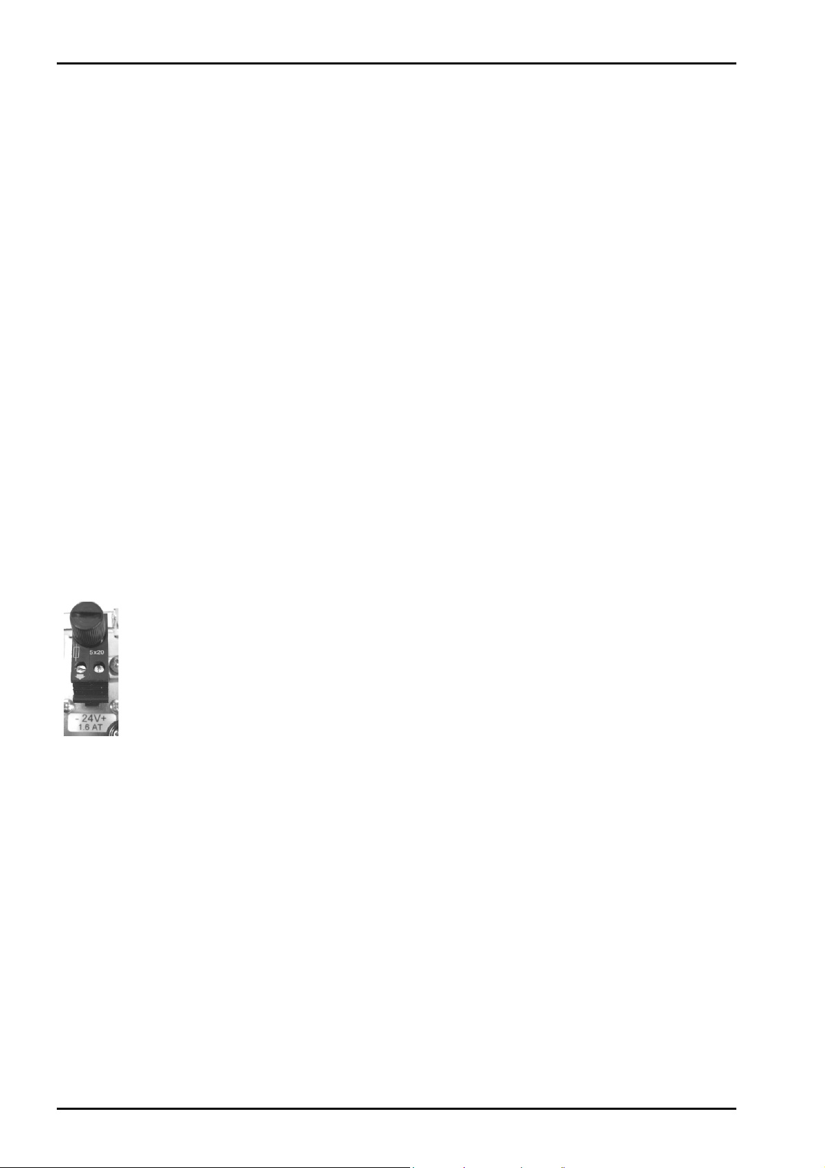
1.3.4.1 Power Connection 24 VDC PR5410/01
The version PR5410/01 is designed for 24 V direct current.
The supply is done with two screw terminals (- 24V +), the instrument is protected against
wrong polarity.
The instrument is protected by a fuse in the + conductor on the back panel of the housing.
1.3.5 Failure and Excessive Stress
If there is any reason to assume that safe operation of the instrument is no longer ensured, shut it down
and make sure it cannot be used. Safe operation is no longer ensured if any of the following is true:
- The instrument is physically damaged
- The instrument does not function
- The instrument has been subjected to stresses beyond the tolerance limits (e.g., during storage or
transport).
1.3.6 Important Note
Make sure that the construction of the instrument is not altered to the detriment of safety. In particular,
leakage paths, air gaps (of live parts) and insulating layers must not be reduced. Sartorius cannot be held
responsible for personal injury or property damage caused by an instrument repaired incorrectly by a user or
installer.
8 Sartorius
Page 9

X3 Operating Manual Process Indicator
2 Process Indicator
The instrument is equipped with a six-digit 7-segment display and additional status indication. Local
operation is performed using 6 double-function keys.
2.1 Overview of the Instrument
- Accuracy 10,000 e (Class III) for the weighing electronics
- High-speed conversion with response times from 10 msec
- Weight indication with status by transflective 6-digit 7-segment display
- 6 function keys for front-panel operation
- Front panel rated to IP 65, back panel to IP30
- LAN adapter with 10/100 Mbit/sec (built-in)
- RS-232 interface, built-in; for connecting e.g. a printer or a remote indicator
- Expansion possible by addition of plug-in circuit boards (2 slots)
- Galvanically isolated interfaces (except RS-232, analog input and BCD output)
- Wide range power supply for 100 to 240 V AC, protection class I (protective earth)
- Version PR 5410/01 for 24 VDC direct current
- Plug-in connections on the back panel for load cells, inputs/outputs, LAN adaptor
- Suitable for mounting in a panel cut-out or a control cabinet
- Calibration using front keys or PC tool (Browser/VNC)
- Calibration using weights, by entering mV/V values,
or directly, using load cell data ("smart calibration")
- Software configuration of the interface cards, e.g. for remote display or printer
- Analog test for the weighing electronics
Communication protocols:
For the internal RS-232 or RS-232/-485 (see Accessories):
- Remote display
- Printer, standard or legal for trade
- JBUS/MODBUS (slave)
- SMA
- Asycom
Fieldbus slave with PR 1721/3x (see Accessories):
- Profibus-DP
- Interbus-S
- DeviceNet
- EtherNet/IP
or PR 5510/14 Ethernet for Modbus TCP/IP
Sartorius 9
Page 10
Process Indicator X3 Operating Manual
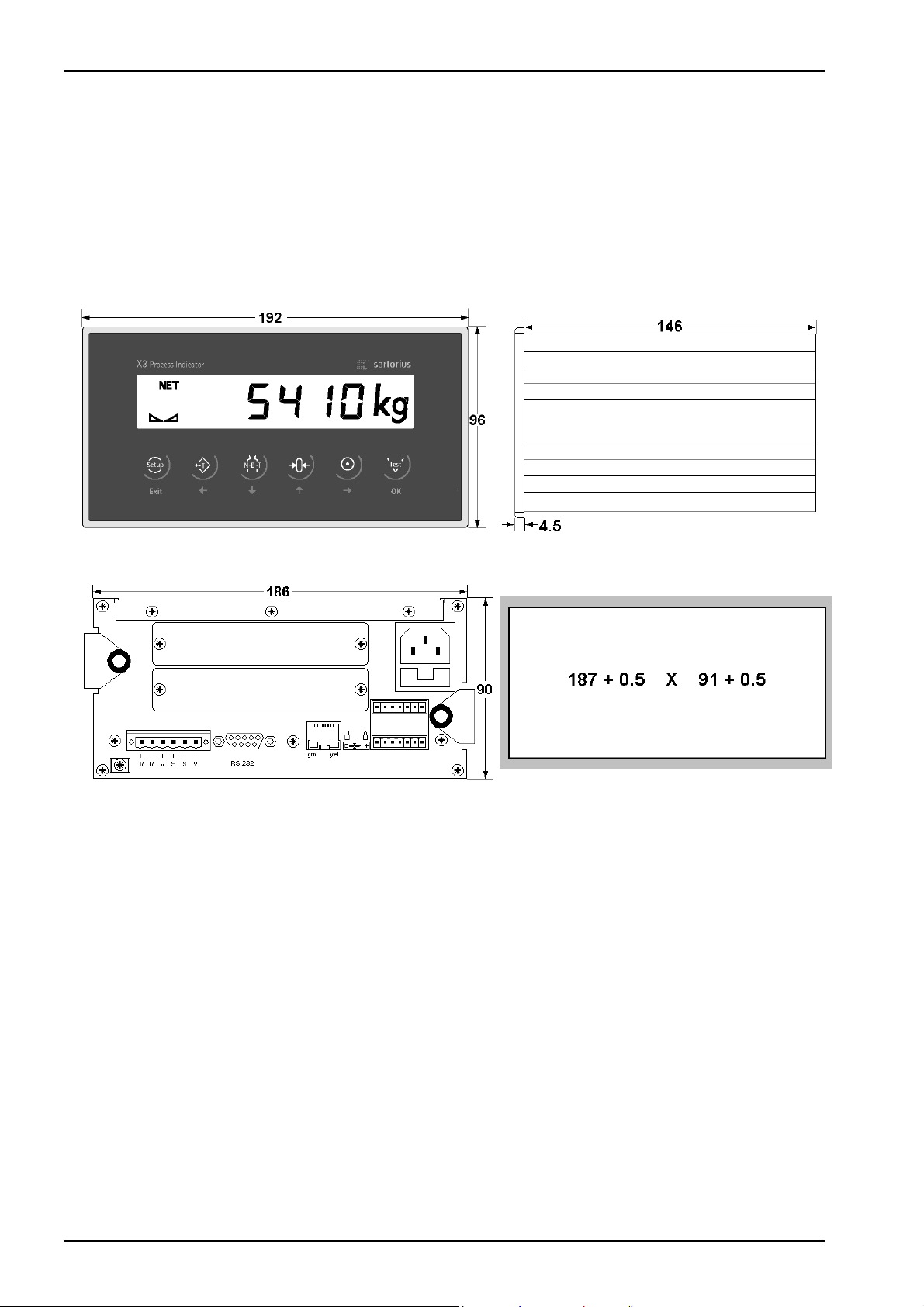
2.2 Housing
The instrument has an aluminium housing and a front panel compliant with IP 65. It is suitable for
installation in a control cabinet. Keypad, display and display board form a unit with the front panel. A
square cut-out is required for installation. The cable connectors are on the back panel of the housing. A 6pin plug-in terminal block is provided for connection of the load cells. The built-in serial interface has a 9contact D-Sub female connector. Network connection is possible via the built-in RJ-45 LAN socket. 3
optocoupler inputs and 3 optocoupler outputs can be connected using plug-in terminals.
The cut-outs for up to 2 plug-in cards are covered by dummy plates.
The power cable plugs into the built-in power connector (with fuse socket).
Front view Side view
View from the back Panel cut-out
10 Sartorius
Page 11
X3 Operating Manual Process Indicator
2.3 Display and Controls
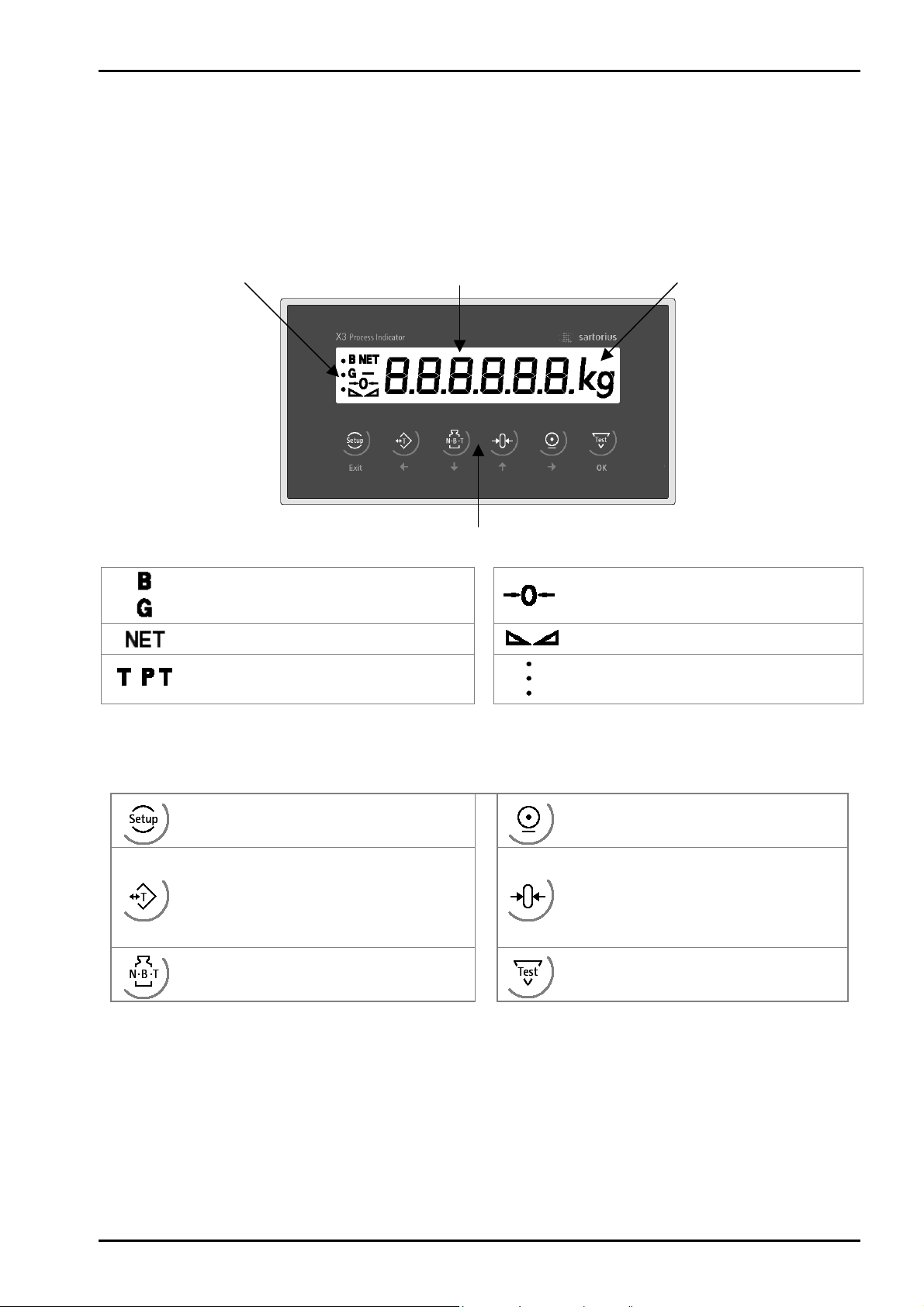
2.3.1 Display
The display permits indication of 6-digit weight values (digit height 18 mm) with decimal point and polarity
sign.
Possible units of mass are t, kg, g or lb.
Status indication Weight value Mass unit
Front keys (Indicator / navigation)
The weight value is within +/- ¼ d of
zero
Stability of the weight value
Range indication
,
Gross weight display
(G with NTEP or NSC mode)
Net weight display
Tare weight or fixtare display
2.3.2 Front-Panel Keys
Indicator keys
Instrument settings, set-up
Taring, the current gross weight is stored
in the tare memory, provided that:
- weight value is stable
- indicator not in error status
(function dependent on configuration)
Selection of display mode:
gross – net – tare weight
Calibration and parameter input using front keys is described in chapter 4.3 .
Start printing
Set gross weight to zero, provided that:
- weight value is stable
- weight within zero setting range
(function dependent on configuration)
Analog test, weighing function
Sartorius 11
Page 12
Process Indicator X3 Operating Manual
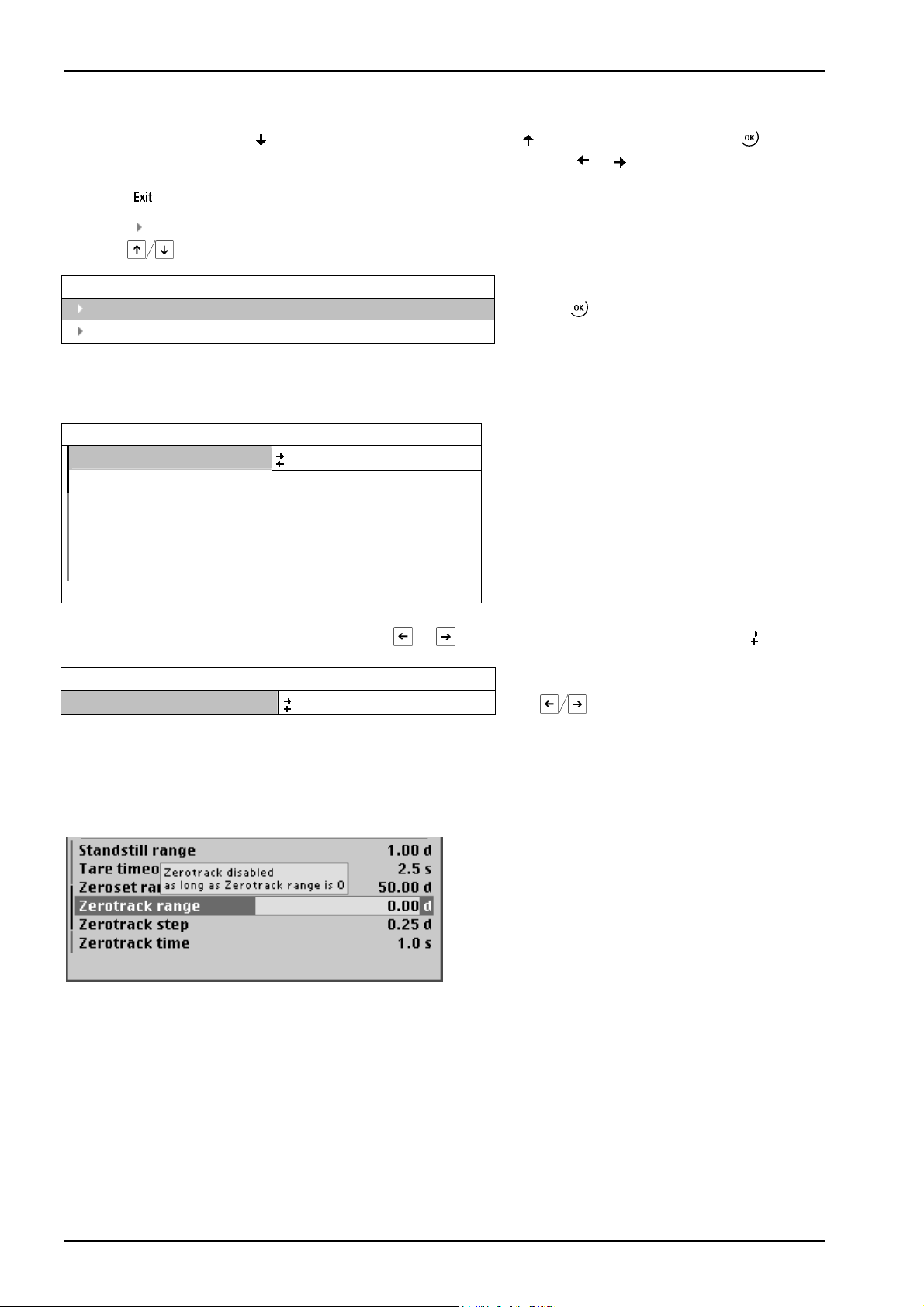
2.3.3 Selection Using the Navigation Keys (VNC)
Press the down arrow key
a menu item. To choose the desired setting for the selected menu, press
Press the key to exit a menu and continue the operation on the next higher level.
An arrow in front of a menu item indicates that there are menu sublevels. The menu item selected by
pressing
is shown inversely.
Show version
Show status
If the list of menu items is long, a vertical bar graph on the left (black and gray) shows which part of the list
is displayed.
WP A/Calibration
Measuretime
Digital filter off
Test mode absolute
W & M
Standstill time 0.50 s
Standstill range 1.00 d
Availability of settings options (selectable with
WP A/Calibration
Measuretime
2.3.4 Tool Tip (VNC)
The 'tool tip' indicates valid value ranges or important properties in a pop-up window, see example:
to scroll down, or the up arrow key to scroll up in a menu. Press to select
or .
Info
Press the key to select an item.
320 ms
none
or ) is indicated by preceding double arrows .
640 ms
Press
to select the measuring time.
This is a warning, that the zero tracking is not activated, if the Zerotrack time is set to 0.
12 Sartorius
Page 13
X3 Operating Manual Process Indicator
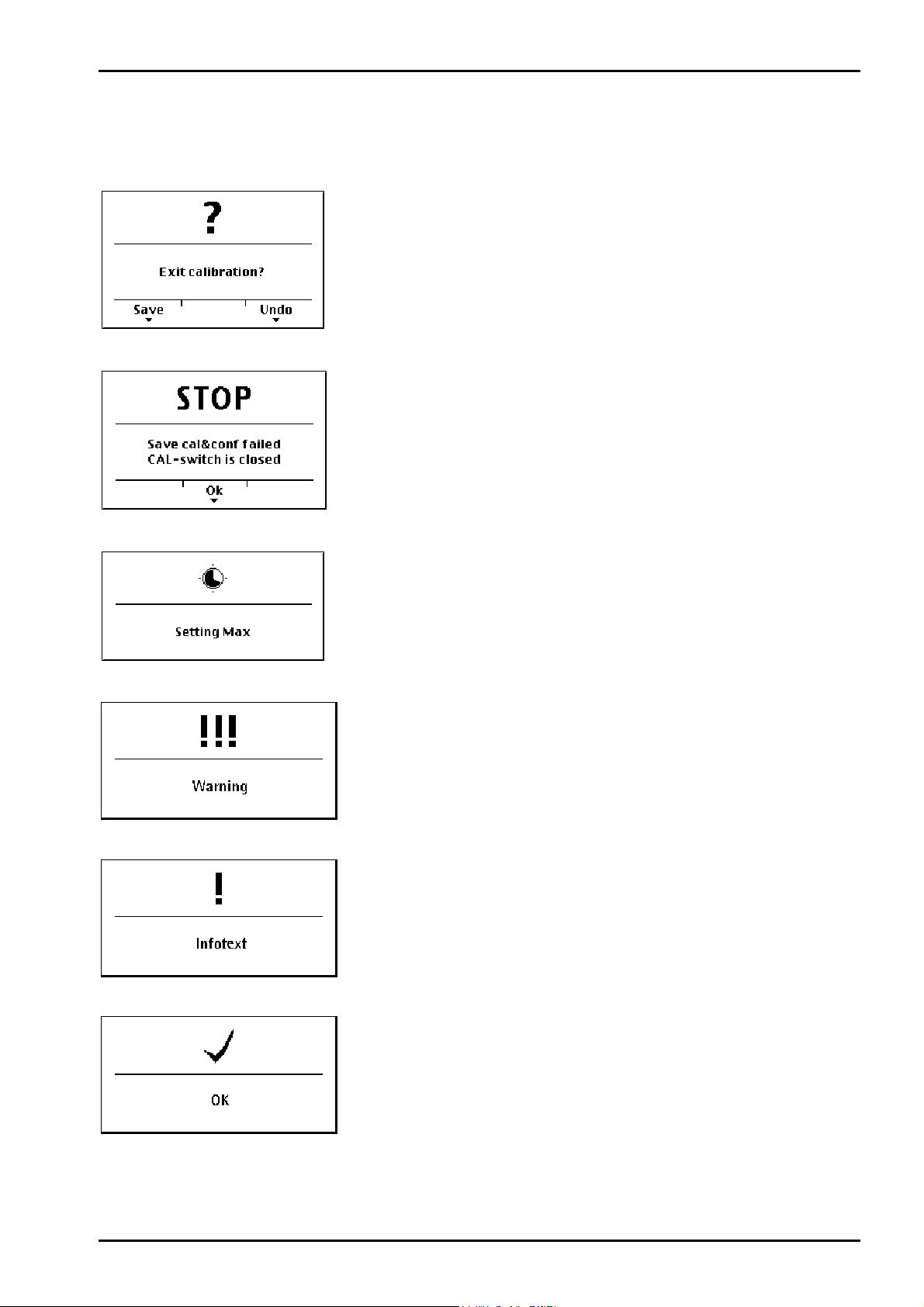
2.3.5 System Messages during Input (VNC)
The following types of messages are displayed as confirmation prompts / warnings during input:
Question mark
A question mark indicates that a choice of options (e.g. [Save] for
saving or [Undo] for cancelling) is available.
“Stop“
An important indication that an action cannot be executed (e.g., if
saving is not possible because the CAL switch is closed). Read the
description and press [OK] to continue:
Processing is in progress
Warning
Informational text
If an action takes a long time (e.g., Max for setting the full scale
deflection), a clock symbol is shown.
A warning is marked by three exclamation points.
An informational text is marked by one exclamation point.
Execution message
Successful execution of an action is indicated by a checkmark.
The graphics are not always included when system messages are depicted in this manual.
Sartorius 13
Page 14
Process Indicator X3 Operating Manual
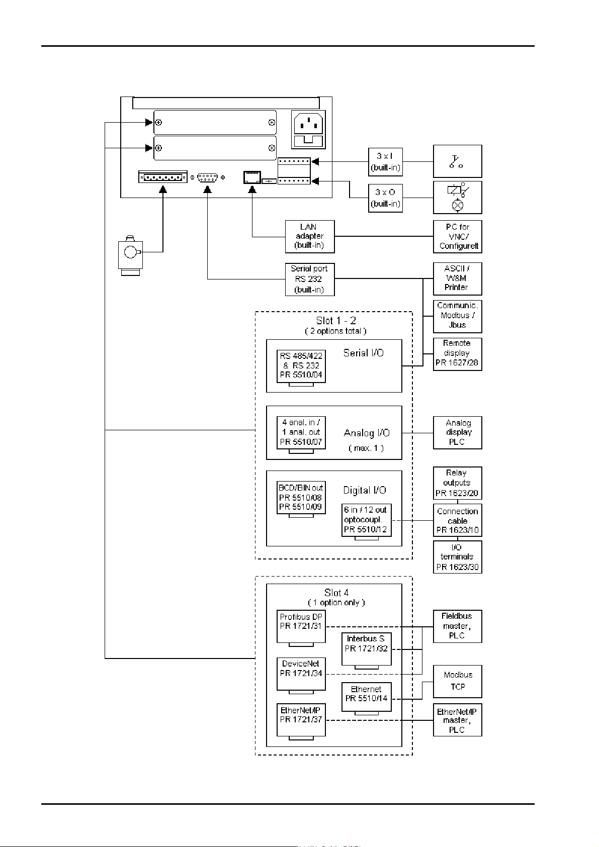
2.3.6 Overview of Accessories
14 Sartorius
Page 15

X3 Operating Manual Process Indicator
2.3.7 Plug-in Cards
On the main board, the PR 5410 Process Indicator can be fitted with up to 2 plug-in cards. Mounting
different types of cards on Slots 1 and 2 is mandatory (exception: PR 5510/04)!
If a card is fitted on Slot 4, only one more card may be mounted on Slots 1 or 2.
Product Function Position
PR 5510/02
2 serial RS-232 interfaces
PR 5510/04
1 serial RS-232 interface and
1 serial RS-485/RS-422 interface.
PR 5510/07
1 analog output,
4 analog inputs
PR 5510/08
BCD output
PR 5510/09
BCD output
PR 5510/12
6 optocoupler inputs and
12 optocoupler outputs
PR 5510/14
Ethernet
PR 1721/31
Profibus-DP slave
PR 1721/32
Interbus-S slave
PR 1721/34
DeviceNet slave
PR 1721/37
EtherNet/IP
For product details, see chapter 3.3.3 .
Protocols and parameters are adjustable via
software.
The serial RS-485/-422 interface is
configurable using DIL switches on the card.
Protocols can be selected via software.
16-bit analog output, 0/4 - 20 mA.
Input: 4 channels with common ground,
3000 d resolution (max. 1 card)
Output: 5 decades + plus or minus sign or 3
bytes binary, open emitter. 1 input
Output: 5 decades + plus or minus sign, or 3
bytes binary, open collector. 1 input
Digital interfaces electrically isolated via
optocouplers. Passive inputs and outputs.
10 / 100 Mbit/s Modbus TCP Slot 4
Profibus-DP to IEC 61158 with
max. 12 Mbit/s
Interbus-S slave with up to 2 Mbit/s Slot 4
DeviceNet slave with max. 500 kbit/s Slot 4
10 / 100 Mbit/s EtherNet/IP Slot 4
Slot 1 or 2
Slot 1 and/or
2
Slot 1 or 2
Slot 1 or 2
Slot 1 or 2
Slot 1 or 2
Slot 4
Sartorius 15
Page 16
Installing the Instrument and Plug-in Cards X3 Operating Manual
3 Installing the Instrument and Plug-in Cards
Before starting work, please read Chapter 1 and follow all instructions.
Further procedures:
• Check the consignment: unpack the components specific to the application.
• Safety check: inspect all components for damage.
• Make sure the on-site installation is correct and complete including cables, e.g. power cable fuse
protection, load cells, cable junction box, data cable, console/cabinet, etc.
• Follow the instructions for installation of the unit relating to application, safety, ventilation, sealing and
environmental influences).
• If necessary, mount the plug-in cards (instrument must be disconnected from all voltage sources).
• Connect the cable from cable junction box or platform/load cell.
• If applicable: connect other data cables, power cable, etc.
• Connect the instrument power cable.
• Check the installation.
3.1 Mechanical Preparation
For cabinet or panel mounting, a corresponding cut-out for the housing must be provided (see Chapter
2.2).
Have all required parts, technical documents and tools at hand for mounting. Secure the cable at the place
of installation; e.g., using cable ties. Remove the insulation from the cable ends, keep the strands short and
fit them with ferrules.
3.2 Hardware Construction
The electronics are contained on two printed circuit boards: the main board and the display board. The
display board is connected to the main board by a plug.
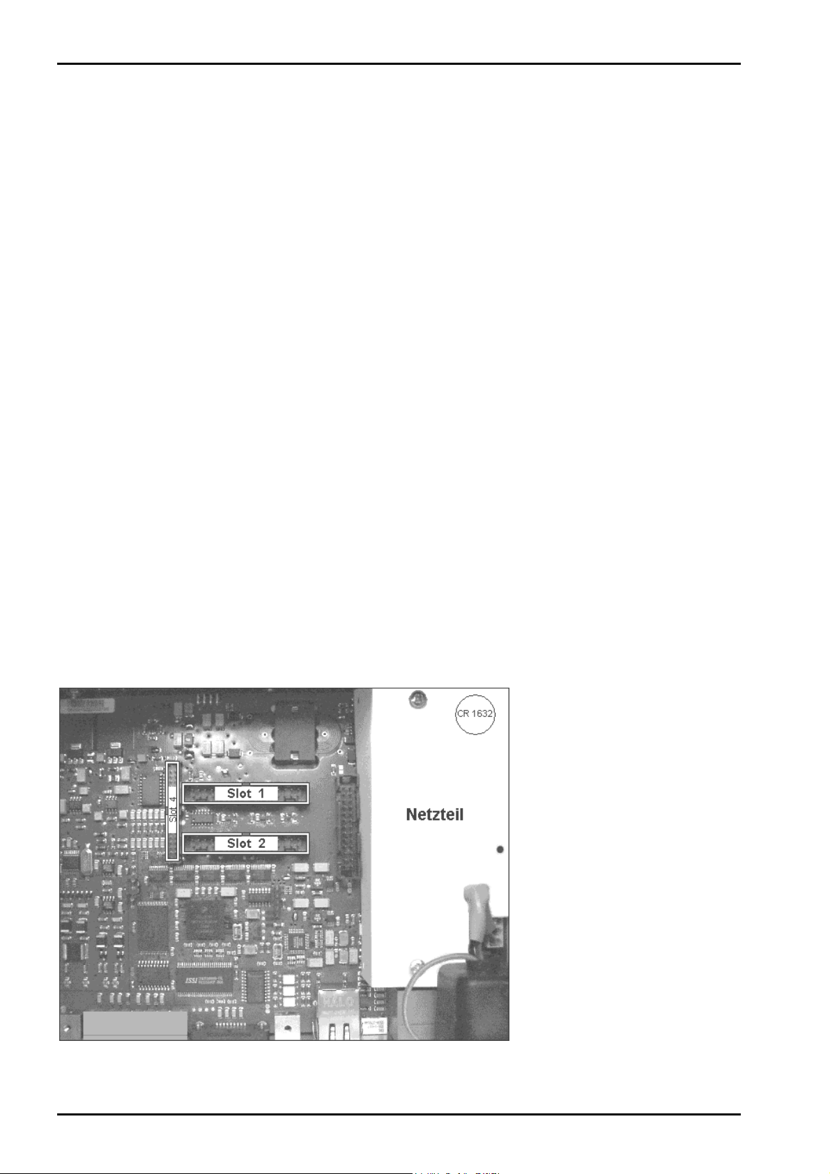
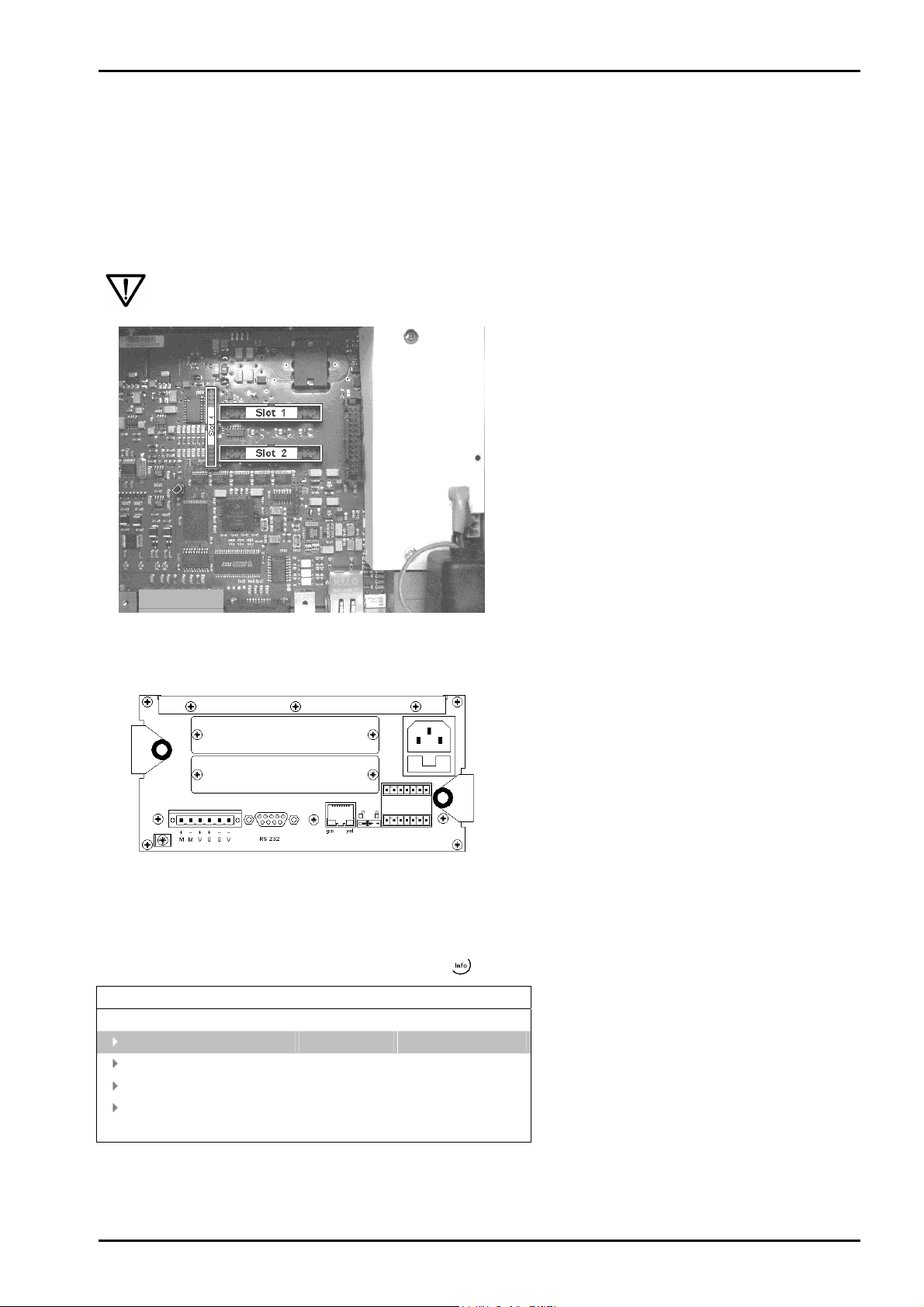
3.3 Main Board
The lithium battery (under the
cover for the power supply) is
always activated and energizes the
calendar/clock module.
The main board holds the power
supply and Slots 1, 2 and 4 for
additional cards.
Load cell connector, serial
interface, LAN adaptor, CAL switch
as well as 3 inputs and outputs are
accessible on the back panel.
Load cell
connector
16 Sartorius
RS-232
LAN
CAL
3 inputs
3 outputs
Page 17
X3 Operating Manual Installing the Instrument and Plug-in Cards
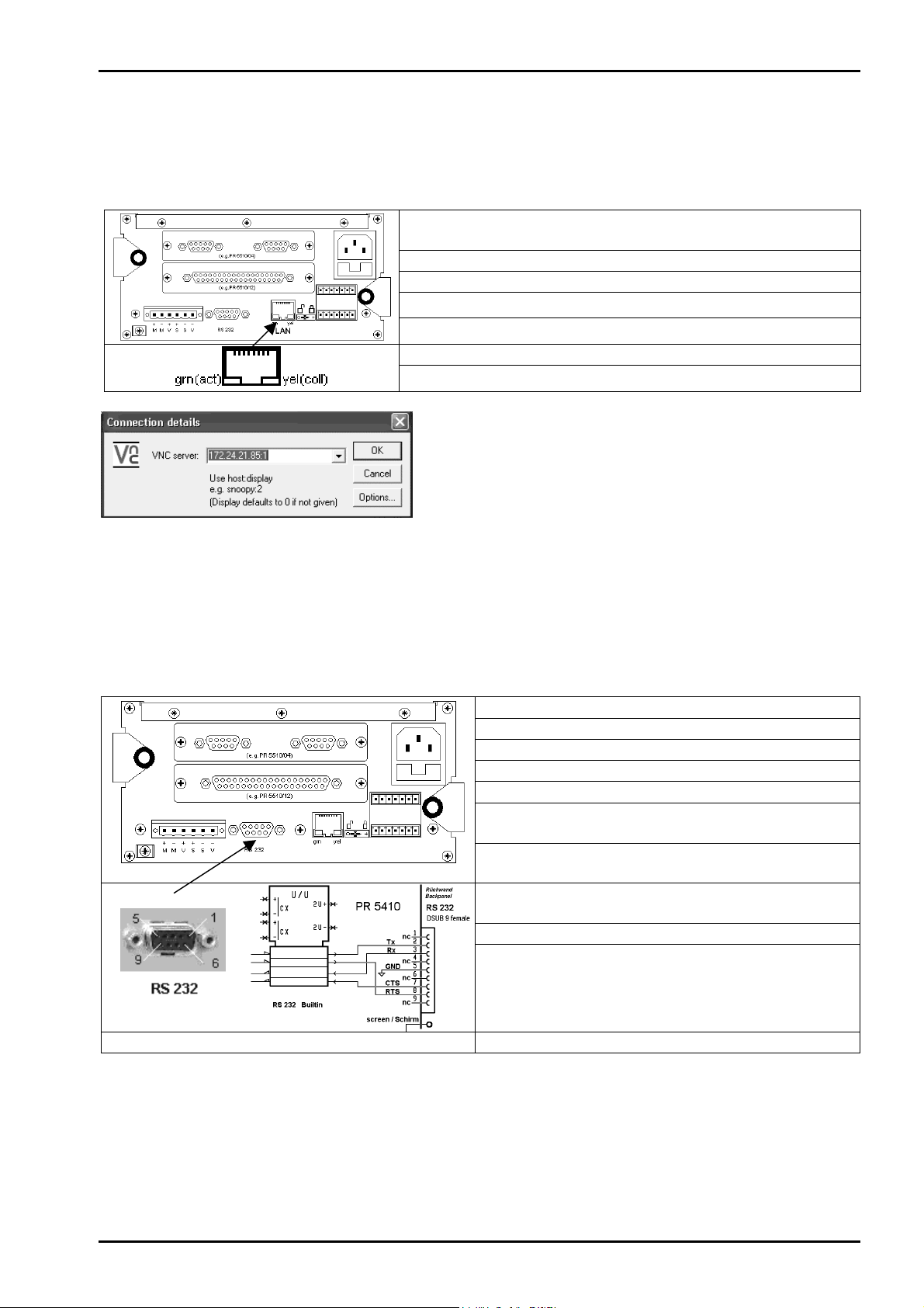
3.3.1 Network Port
The network port is built in as standard equipment. The port contains powerful TCP/IP connection circuitry
with transfer rates of 10 or 100 Mbit/sec. The LEDs on the connector indicate whether the port is
functioning.
Transfer rate:
Connection method:
Cable:
Cable impedance:
Electrical isolation:
Cable length :
Connection :
Remote operation of the PR 5410 indicator from the PC is
possible; install version 3.3.7 VNC program on the PC. For
setting the network address, see Chapter 4.2.4.
10 Mbit/s, 100Mbit/s,
full / half duplex, auto-detection
Point to point
CAT 5 patch cable, shielded twisted pair
150 ohms
Yes
Max. 115 m
RJ-45 socket on back panel of housing
3.3.2 Standard RS-232 Interface
The instrument is provided with a built-in RS-232 interface that is accessible on the back panel of the
housing. This interface is configurable, and can be used, for example, for data transmission to a remote
display or a printer.
Number of channels:
Type:
Transfer rate:
Parity:
Data bits:
Input signal level:
Output signal level:
Number of signals:
Electrical isolation:
Cable type:
1
RS-232, full duplex
300 to 115K2 bit/s
none, odd, even
7 / 8 bits
logic 1 (high) - 3 ... - 15 V
logic 0 (low) + 3 ... + 15 V
logic 1 (high) - 5 ... - 15 V
logic 0 (low) + 5 ... + 15 V
2 output signals (TXD, RTS)
2 input signals (RXD, CTS)
none
shielded twisted pair
(e.g. LifYCY 3x2x0,20),
1 pair of wires for GND
Connection:
Sartorius 17
9-pin D-Sub socket (female)
Cable length:
max. 15 m
Page 18
Installing the Instrument and Plug-in Cards X3 Operating Manual
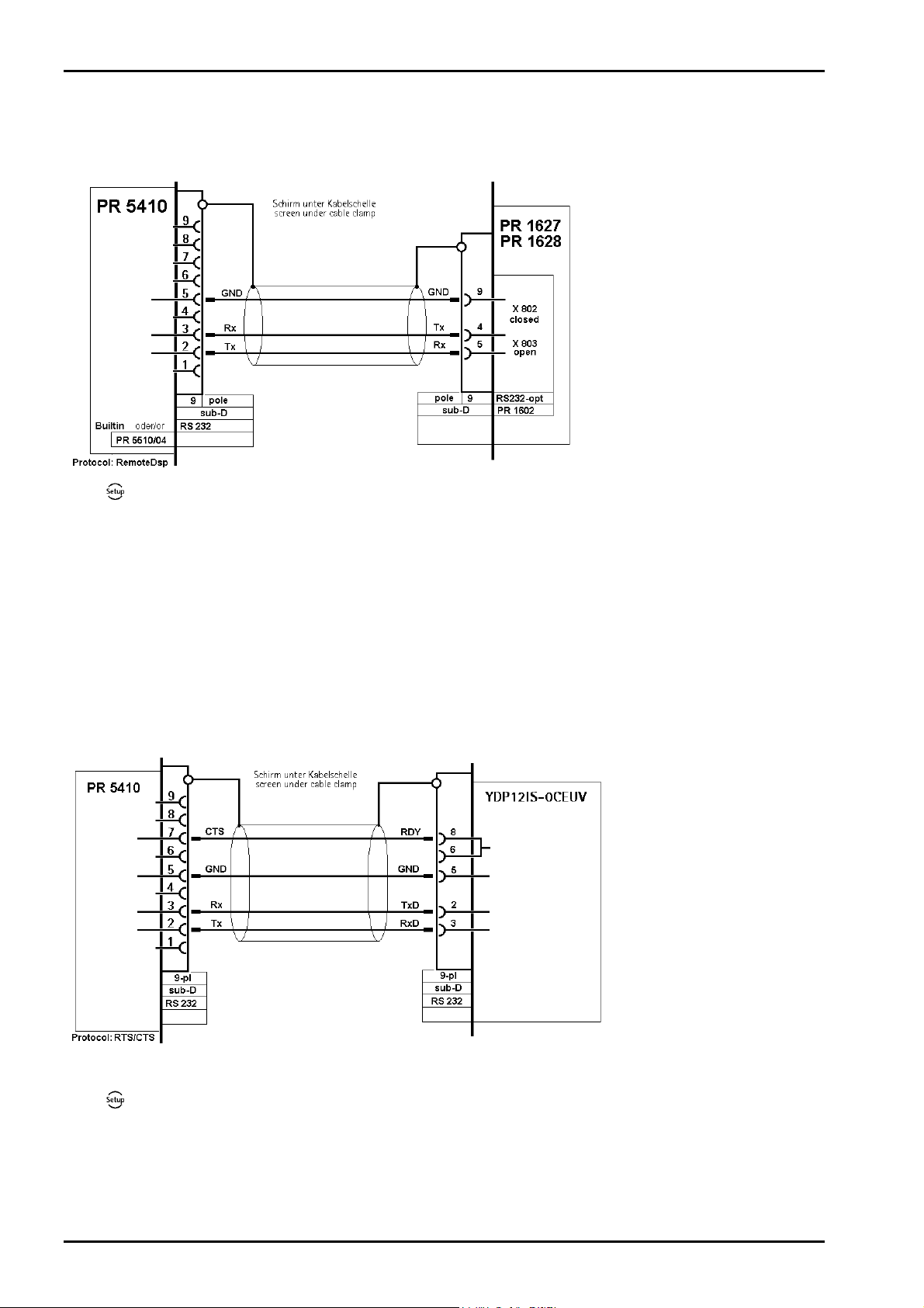
3.3.2.1 Connecting a Remote Display / Remote Terminal
A PR 1627 remote display or a PR 1628 remote terminal can be connected to the built-in RS-232 interface
[Builtin RS232] or to the PR 5510/04 card.
Press
baud rate now corresponds to the default settings of PR 1627 or PR 1628.
The following settings cannot be changed: [Bits] 7, [Parity] even and [Stopbits] 1.
If only one instrument is connected to a PR1627/8, [Mode] must be [single transmitter].
When connecting several instruments to a PR 1628 via an RS-232/RS-485 converter, selection for display on
PR 1628 is possible using addresses. For this purpose, select [multiple transmitters] as [Mode] in all
instruments, enter the instrument address under [Device Id] and the address of the subsequent instrument
under [Next Device Id].
3.3.2.2 Connecting a YDP12IS or YDP04IS Ticket Printer
The ticket printer YDP12IS-OCEUV or YDP04IS-OCEUV can be connected via [Builtin RS232] interface or the
RS-232 on card PR 5510/04.
-[Serial ports parameters]-[Remote display]-[Builtin RS232]-[Param] and select [Baudrate] 4800. The
If the printer is connected to the [Builtin RS232] port:
Press
-[Serial ports parameter]-[Printer]-[Builtin RS232]-[Param] and configure the following settings
under [Protocol]: [RTS/CTS], [Baudrate]: 9600, [Bits]: 8, [Parity]: [none], [Stopbits]: 1 and [Output mode]:
[Raw].
The printer must be set to Line Mode (factory setting: Page Mode). Press the 'FEED' button to change
modes; please refer to the installation instructions delivered with the printer.
18 Sartorius
Page 19
X3 Operating Manual Installing the Instrument and Plug-in Cards
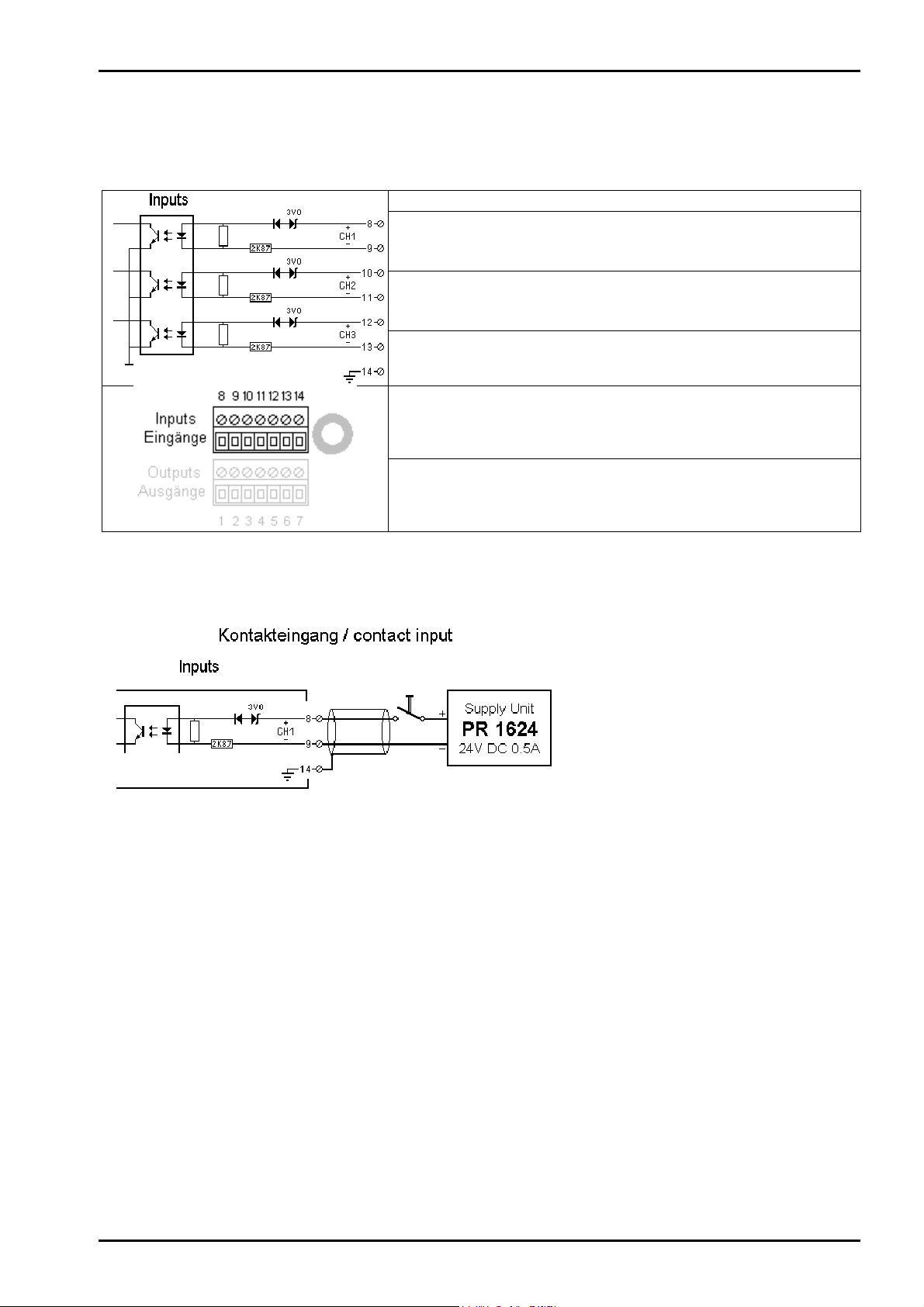
3.3.3 Optocoupler Inputs
The main board has 3 digital inputs for process control, electrically isolated by optocouplers, each bipolar
potential-free.
Number of inputs:
Input signal:
Input current:
3 ( CH1, CH2, CH3 )
Logic 0: 0 to 5 VDC or open
Logic 1: 10 to 31 VDC
Passive, external supply required
< 7 mA @ 24 V
< 3 mA @ 12 V
Protected against incorrect polarity
Example: connection of a contact input
Electrical isolation:
Connection:
Cable:
Yes, via optocoupler
Plug-in 7-pin screw terminal block,
cable shield connected to housing
(terminal 14), max. 1.5 mm² cable.
Shielded, max. 50 m
Sartorius 19
Page 20
Installing the Instrument and Plug-in Cards X3 Operating Manual
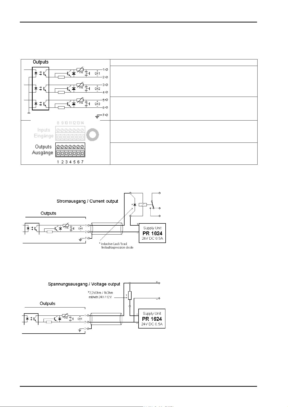
3.3.4 Optocoupler Outputs
The main board has 3 digital outputs for process control, electrically isolated by optocouplers, each bipolar
potential-free.
Number of outputs:
Output:
3 ( CH1, CH2, CH3 )
Max. switching voltage: 31 VDC,
Protected against incorrect polarity
Max. switching current: 25 mA
Voltage drop @ 25 mA: 3 V
Passive, external supply required
Example: connection of relay control
Electrical isolation:
Connection:
Cable:
Yes, via optocouplers
Plug-in 7-pin terminal block, cable
shield connected to housing (terminal
7), max 1.5 mm² cable
Shielded, max. 50 m
The relay switches, when the output is
active (true). For protection of the
output circuit, relays with free-wheel
diode must be provided.
Example: connection of voltage output
When the output is active (true), the
output voltage goes from 24 V / 12 V
to < 3 V . The load resistance must be
2.2 kohms / 1 kohm.
20 Sartorius
Page 21
X3 Operating Manual Installing the Instrument and Plug-in Cards
3.4 Accessories
3.4.1 Installing Plug-in Cards
The main board has two slots with identical pin allocation (34 contact pins in two rows of 17) and another
slot (34 contact pins in two rows of 17) for plug-in cards. The slot designations are “Slot 1 ... 2" and "Slot
4" (left). Up to 2 cards can be mounted. Accordingly, the back panel is provided with two cut-outs for the
retainer plates of the cards.
Before installing or removing a plug-in card, disconnect the instrument from all voltage sources.
Installation (Slots 1-2, 4):
The flat cables plug into connectors ( Slots 1 ...
2, 4) on the main board. The cables are
polarized; i.e. incorrect polarity is precluded.
A description and examples of the various cards
and connections are given in Chapter 3.3.3 .
View from above, back panel connectors at the bottom
Remove the dummies from the back panel (2
screws; M3) and replace them with the retainer
plates for the plug-in cards.
The flat-cable connectors must be inserted into
the corresponding slots on the main board.
View from the back
After installation/modification, the plug-in cards are detected automatically.
To view a list of the installed plug-in cards, select
Info/HW-Slots
Builtin RS 232
Slot 1 PR 5510/04 RS 485/232
Slot 2 -empty-
Slot 3 Builtin Digital I/O
Slot 4 PR 1721/31 Profibus-DP
-[Show HW-slots]:
Built-in serial interface
Slots (Slot 1 and 2) are identical
Built-in digital I/Os
Only Fieldbus cards
Sartorius 21
Page 22
Installing the Instrument and Plug-in Cards X3 Operating Manual
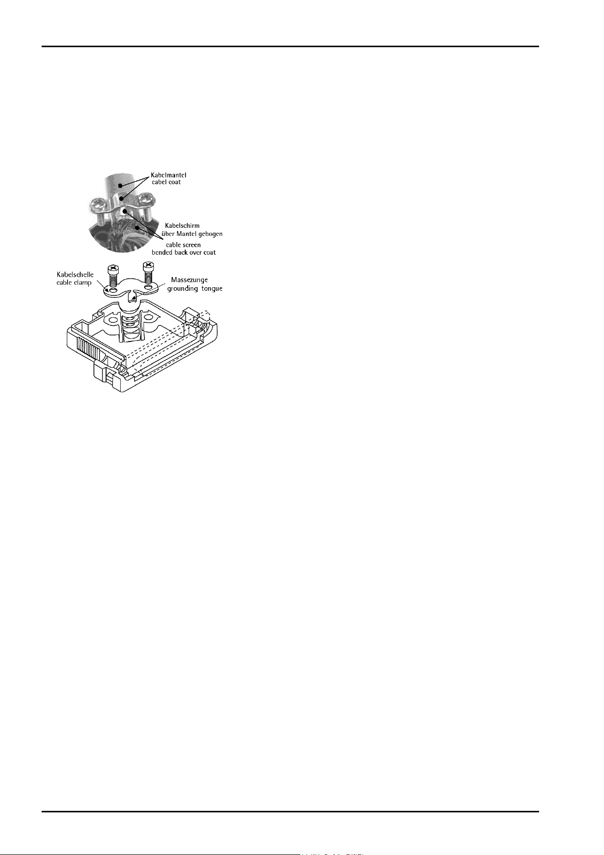
3.4.2 Cable Connection in the D-Sub Connector Mating Plug
The connections on the back panel are plug-in type. Keep the conductors as short as possible and connect
them to the terminals. The connector housings are conductive (metallized), i.e., part of the shield, and must
be fastened to the back panel by screws.
Mounting a cable:
• Open the connector housing (catches)
• Release and open the cable clamp
• Remove approx. 50-60 mm of the cable insulation
• Shorten the shield to 5 mm and bend it over the cable sheath
• Remove 3mm wire insulation and connect it by soldering
• Insert the pin unit
• Put the cable under the cable clamp
The grounding tongue presses on the shield bent backwards;
the clamp presses on the cable sheath
• Close and tighten the cable clamp
• Check the strain relief
• Insert the mounting screws on both sides
• Close the connector housing (catches)
The shields must be connected to the metal housings on both
ends of the cable.
22 Sartorius
Page 23
X3 Operating Manual Installing the Instrument and Plug-in Cards
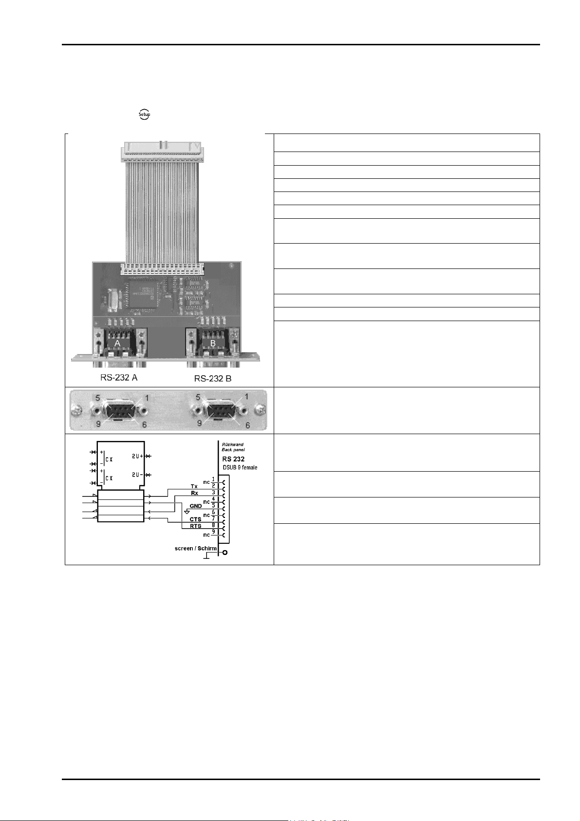
3.4.3 PR 5510/02 Serial I/O
The plug-in card contains two RS-232 channels (A and B), which can be used simultaneously and
independently. Max. 2 PR 5510/02 cards can be plugged in (Slot 1 ... 2). The relevant interface parameters
are adjustable in
-[Serial ports parameter], no additional settings on the card are required.
Internal connection:
Number of channels:
Type:
Transfer rate:
Parity:
Data bits:
Signals RS 232:
Input signal level:
Output signal level:
Potential isolation:
Cable length:
Cable type:
34-pole connector socket
2
RS 232, full duplex
300 to 19k2 bits/sec
No, odd, even
7 / 8 Bit
Output: TX, RTS
Input: RX, CTS
logic 1 (high) - 3 ... - 15 V
logic 0 (low) + 3 ... + 15 V
logic 1 (high) - 5 ... - 15 V
logic 0 (low) + 5 ... + 15 V
No
max. 15m
twisted pairs, screened
(e.g. LifYCY 3x2x0,20),
1 conductor pair for GND.
External connection:
2x D-Sub 9-pole socket (female)
Accessories (delivered
with the unit):
Dimensions: (LxWxH):
Weight:
The RS-232 can only be used as point to point connection. A max. cable length of 10-15m must not be
exceeded.
The PR5510/02 and the 'Builtin' comply with the standard pin allocation, i.e. they are equal in the
connecting diagrams. Accordingly, the RS232 connections are described only for the builtin interface in this
manual (see chapter 3.3.2 ).
2x connector counterpart D-Sub
9-pin (male)
incl. screening hoods
86 x 52 x 15 mm
appr. 30 g
Sartorius 23
Page 24
Installing the Instrument and Plug-in Cards X3 Operating Manual
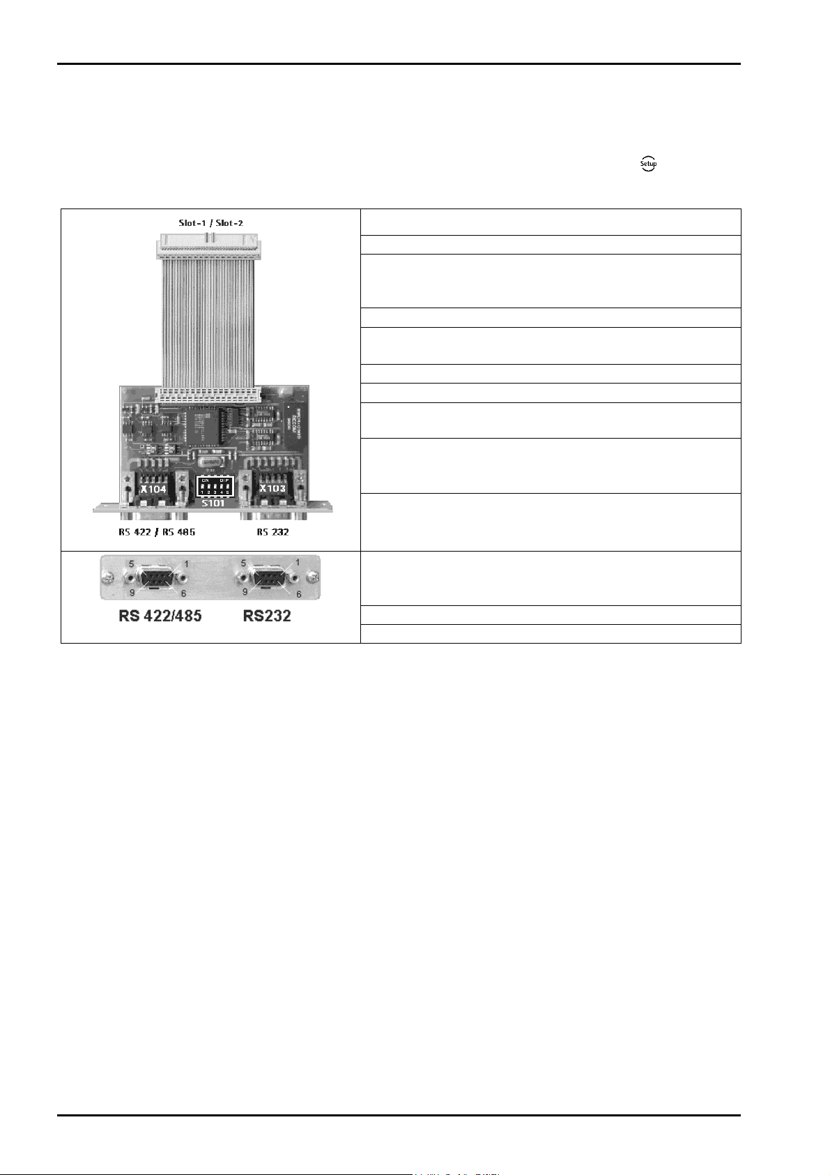
3.4.4 PR 5510/04 Serial I/O
The plug-in card has two channels (1x RS-232 and 1x RS-422/485), which can be used simultaneously and
to a great extent independently. The RS-422/485 interface is electrically isolated. Up to 2 PR 5510/04 cards
(Slot 1 and 2) can be plugged in. The relevant interface parameters can be configured under
parameter]; the DIL switch S101 must be set for RS-422/485 additionally.
Internal connection:
Number of channels:
Type:
Transfer rate:
RS-232C (V24)
signals:
RS-422/485 signals:
Electrical isolation:
Cable length:
Cable type:
External connection:
34-contact socket terminal strip
1x RS-232, 1x RS-422/485
RS-232 full duplex
RS-422/485 full duplex (4-wire) *
RS-485 half duplex (2-wire) *
300 to 19k2 bit/s
Output: TXD, RTS, DTR
Input: RXD, CTS, DCD, RI
TxA, RxA, TxB, RxB
RS-232: no, RS-422 / 485: yes
Max. 15m with RS-232
Max. 1000 m with RS-422 / 485
Shielded twisted pair
(e.g., LifYCY 3x2x0,20),
1 conductor pair for GND.
2 D-Sub 9-contact female
connectors
-[Serial ports
Accessories (delivered
with the unit):
Dimensions: (LxWxH):
Weight:
2 D-Sub 9-pin mating plugs
(male)
incl. shielded housing
86 x 52 x 15 mm
33 g
3.4.4.1 PR 5510/04 RS-232
The RS-232 interface is independent of the S101 switch settings.
It can be used only for point-to-point connection.
PR 5510/04 is provided as an equivalent to the [Builtin RS-232] interface in the RS-232 channel with
additional signals: DCD, DTR, RI.
The built-in and PR 5510/04 interfaces comply with the standard pin allocation; i.e., they are equivalent in
the following connecting diagrams. Thus only the RS-232 connections for the built-in interface are
described in this manual (see Chapter 3.3.2).
24 Sartorius
Page 25

X3 Operating Manual Installing the Instrument and Plug-in Cards
3.4.4.2 PR 5510/04 RS-422/485
When mounting, the RS-485/422 interface must be configured by DIL switch S101 on the card.
Using RS-485 is compulsory with a multi-point connection (tristate status). The RS-485 interface can be
used also for point-to-point connection. Like 2-wire or 4-wire connections, this is dependent on the other
communicating units.
A 2-wire connection is half-duplex and cannot send and receive simultaneously. It requires corresponding
driver programming (see relevant instrument manual).
Factory setting Switch S101 Settings for RS-422/ 485
1: Tristate enable: OFF – RS-422 ON – RS-485
2: Rx enable OFF – 4-wire ON – 2-wire
3: Rx pull-up resistor: OFF – not connected ON - (RxB 1k54 +V)
4: Rx bus termination: OFF – not connected ON - (RxA 205E RxB)
5: Rx pull-down resistor: OFF – not connected ON - (RxA 1k54 -V)
Overview of which switches must be closed (ON) for which mode:
S101
Master RS-485
Individual slave RS-485
Other slaves - RS-485
Last slave - RS-485
Two-wire system Four-wire system
Point to point Bus Point to point Bus
1, 2, 3, 4, 5 = on
1, 2 = on
RS-485
1, 2, 3, 4, 5 = on
- RS-422
1, 2 = on
1, 2, 3, 4, 5 = on
RS-422
4 = on
4 = on
- RS-485
- RS-485
RS-422
3, 4, 5 = on
-
1 = on (default)
1, 3, 4, 5 = on
Sartorius 25
Page 26
Installing the Instrument and Plug-in Cards X3 Operating Manual
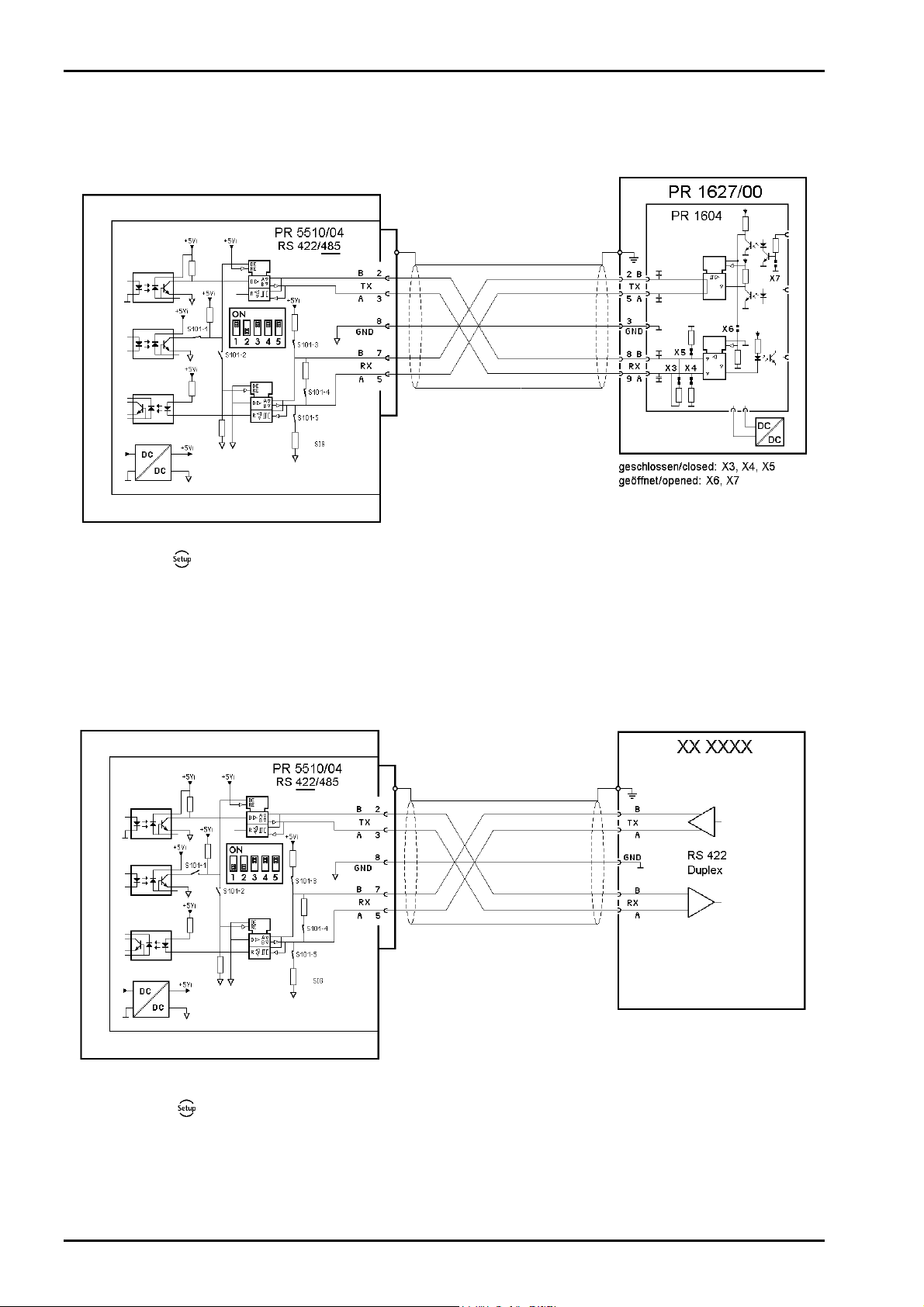
3.4.4.3 Connecting a PR 1627 Remote Display over RS-485
Four-wire transmission, point to point, full duplex (simultaneous sending and receiving possible)
with PR 1627/00 remote display.
Configuration:
-[Serial ports parameter]-[Remote display]-[Slot1/2-RS-485]
3.4.4.4 RS-422 Point-to-Point Connection (Four-Wire)
Four-wire transmission: full duplex (simultaneous sending and receiving possible)
RS-422 can be used only for point-to-point connection.
Configuration:
26 Sartorius
-[Serial ports parameter]-[.........]-[Slot1/2-RS-485]
Page 27
X3 Operating Manual Installing the Instrument and Plug-in Cards
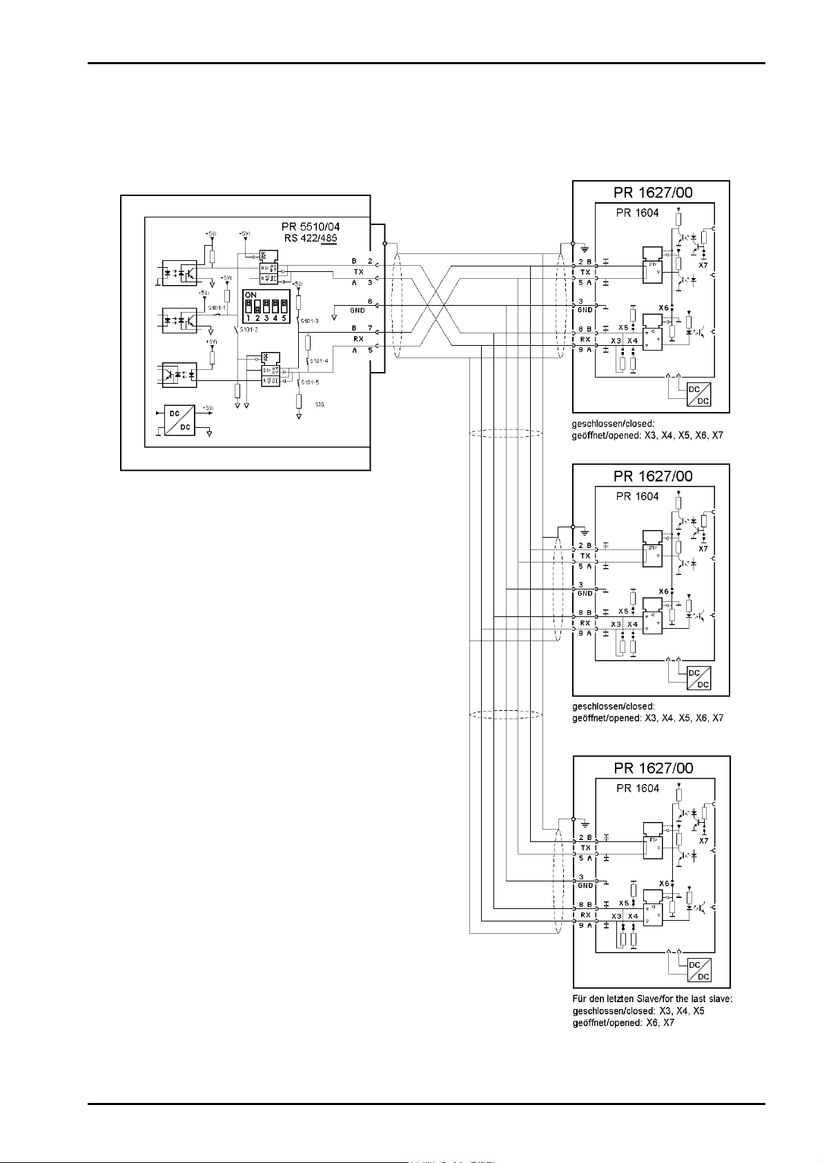
3.4.4.5 Connecting Several PR 1627 Remote Displays over RS-485
Connection of several PR 1627 remote displays over RS-485, four-wire, full-duplex (simultaneous sending
and receiving possible):
Sartorius 27
Page 28
Installing the Instrument and Plug-in Cards X3 Operating Manual
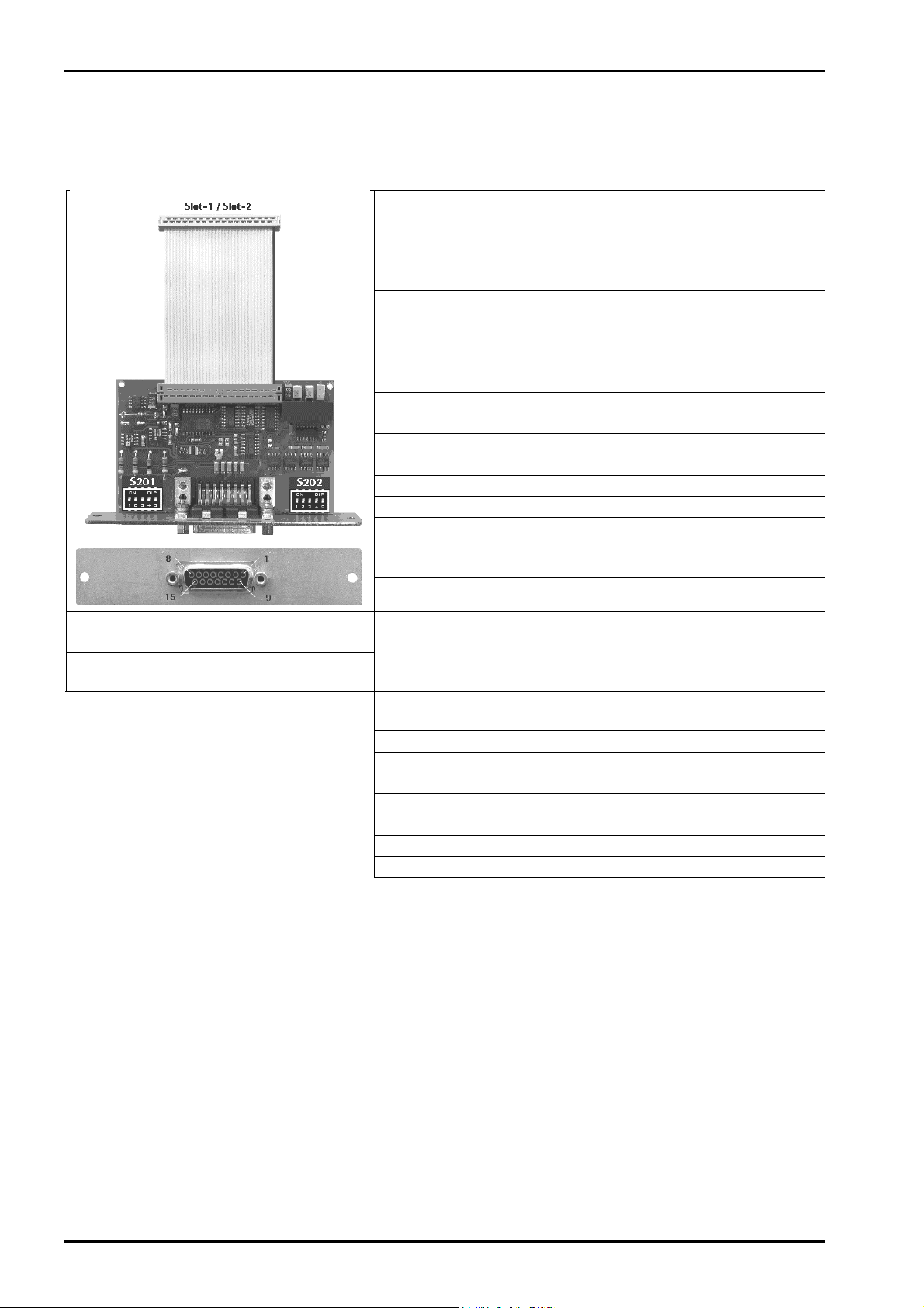
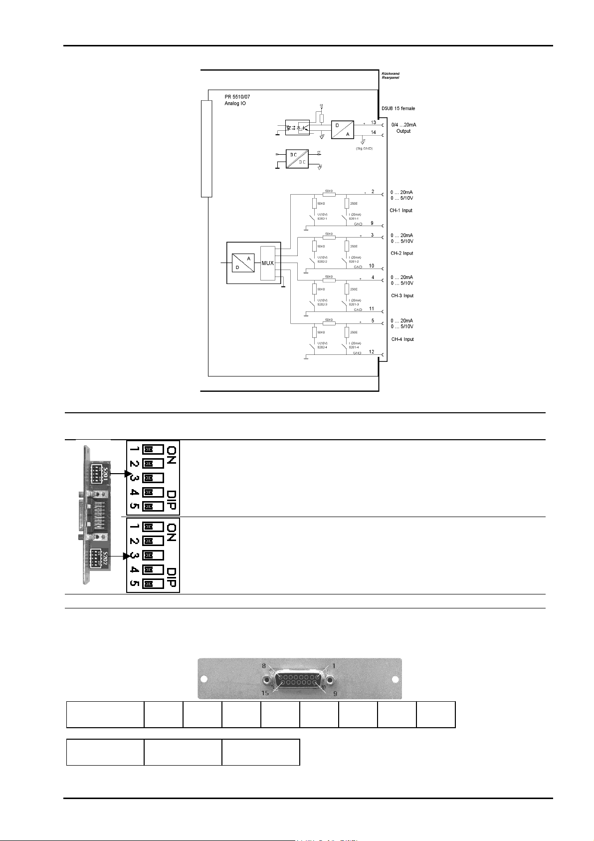
3.4.5 PR 5510/07 Analog Input/Output Card
The plug-in card with 15-contact D-Sub socket for the analog channels is configured as 1 analog output
(active) and 4 analog inputs. The analog inputs are not supported by the standard instrument.
Internal connection:
Number of outputs:
Output assignment:
Output range:
Output resolution:
Output linearity
error:
Output temperature
effect:
Output zero error:
Max. output error:
Load:
External connection:
34-contact connector socket on flat
cable for Slot 1, 2
1 active current output: 20mA, 10V
output voltage via external 500 ohm
resistor
Gross / net / display following,
configurable
0/4 ... 20mA, configurable
16 bits binary,
20,000 internal counts @ 20 mA
@ 0 - 20mA: 0.04 %
@ 4 - 20 mA: 0.02 %
< 100 ppm/K
0.05 %
< 0.1 %
Max. 0 ... 500 ohms
15-contact D-Sub female connector
Dimensions:
(LxWxH):
Weight:
86x53x16mm
40g
Accessories:
Inputs:
Input resolution:
Input accuracy:
Input,
linearity error:
Input
temperature effect:
Input, reserve:
Electrical isolation:
15-pin D-Sub male connector
4 channels current or voltage input
0 ... 20 mA, input resistance 250 ohms
0 ... 10 V, input resistance 100 kohms
0 ... 5 V, input resistance >10 Mohms
3,000 internal counts corresponding to
e.g. 0 - 20 mA / 0 ... 10 V
0.2 %
< 0.03 %
< 50 ppm/K
+- 15%, i.e. –1.5V ... +11.5V
Output: yes, inputs: no
28 Sartorius
Page 29
X3 Operating Manual Installing the Instrument and Plug-in Cards
Analog input
Signal selection
Input resistance
Channel
CH1
S201
CH2
CH3
CH4
----
CH1
S202
CH2
CH3
CH4
----
Current
0...+ 20mA DC
ON
ON
ON
ON
----
OFF
OFF
OFF
OFF
---250 ohms 100 kohms > 10 Mohms
Pin allocation of rear socket (for installation, see Chapter 3.4.1)
D-Sub 15
Voltage
0...+ 10V DC
OFF
OFF
OFF
OFF
----
ON
ON
ON
ON
----
Voltage
0...+ 5V DC
OFF
OFF
OFF
OFF
----
OFF
OFF
OFF
OFF
----
Input (PIN) 2 9 3 10 4 11 5 12
4 channels + CH1 GND + CH2 GND + CH3 GND + CH4 GND
Output (PIN) 13 14
1 channel + 0/4 ... 20 mA Sig GND
Sartorius 29
Page 30
Installing the Instrument and Plug-in Cards X3 Operating Manual
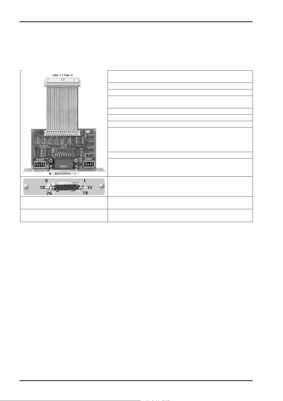
3.4.6 PR 5510/08 BCD Output (Open Emitter)
The plug-in card is used for BCD-coded output of a 5-decade weight value.
Cyclical output of the weight value with 4-bit (plus or minus sign, stability, error). The value is intrinsically
consistent and can be output continuously or the digital input DATA_IN control can be used to freeze (hold)
the value.
Internal connection:
Number of outputs:
Number of inputs:
Output stage:
External supply:
Voltage drop:
Output current:
Enable input:
Cable:
Electrical isolation:
External connection:
X102
Dimensions
(LxWxH):
Weight:
Before installing the card, set switches S101 and S102; see Chapter 3.4.7.1.
60x106x22
55 g
Accessories (delivered
with the unit):
34-contact female connector on flat
cable for Slot 1, 2
5 digits BCD + plus or minus sign
Input: 1 bit (DATA IN)
Common collector at +Uext.,
open emitter
+5 V ... +24 VDC
Approx. 1.7 V
Max. 50 mA
5 V / 24 V adjustable via S101
@ 5 V high > 3.1 V, low < 1.5 V
@ 24 V high > 16 V, low < 10V
protected against incorrect polarity
Shielded, max. 50 m
No
26-contact D-Sub connector (female)
26-pin D-Sub mating plug (male)
incl. shielded housing
30 Sartorius
Page 31

X3 Operating Manual Installing the Instrument and Plug-in Cards
External supply voltage required: pin 1 - Uext, reference potential pin 26 – GND
Sartorius 31
Page 32

Installing the Instrument and Plug-in Cards X3 Operating Manual
Outputs
The PR 5510/08 outputs (pins 2 - 24) use common supply voltage at the collector as reference potential
and open emitter outputs. A non-activated output has high impedance, and an active output has a voltage
by approximately 1.7 V lower than the supply voltage.
The load to be connected is applied between the output (pins 2 … 24, 25*) and GND (pin 26).
Input
When using as DATA_IN, the input (pin 25) can control the 23 outputs. As an output, data is
“continuous/hold/tristate“ and its signal can be configured (TTL/24V active (high/low). It is applied to pin
25 – DATA_IN of the 26-pin connector and is effective only with DIL switch S101-1 = OFF and S101-2 =
ON.
The meaning of switches is given in the table in Chapter 3.4.7.1.
PR 5510/08 connector pin allocation:
BCD output for the weight value
Output circuitry
3.4.6.1 Output Modes
The output modes are identical with the PR 5510/09 card; see Chapter 3.4.7.2
32 Sartorius
Page 33

X3 Operating Manual Installing the Instrument and Plug-in Cards
3.4.7 PR 5510/09 BCD Output (Open Collector)
The plug-in card is used for BCD-coded output of a 5-decade weight value.
Cyclical output of the weight value is with 4-bit corresponding status (polarity sign, stability, error). The
value is intrinsically consistent and can be output continuously or the digital input DATA_IN control can be
used to freeze (hold) the value.
Internal connection:
Number of outputs:
Number of inputs:
Output stage:
External supply:
Voltage drop:
Output current:
Enable input:
Cable:
Electrical isolation:
34-contact female connector on flat
cable for Slot 1, 2
5 digits BCD + plus or minus sign
Input: 1 bit (DATA IN)
Common emitter at GND,
open collector
+5 V ... +24 VDC
Approx. 0.9 V
Max. 50 mA
5 V / 24 V adjustable via S101
@ 5 V high > 3.1 V, low < 1.5 V
@ 24 V high > 16 V, low < 10V
protected against incorrect polarity
Shielded, max. 50 m
No
External connection:
X102
Dimensions:
(LxWxH):
Weight:
Before installation, set the switches S101 and S102 as given in Chapter 3.4.7.1.
60x106x22
55 g
Accessories (delivered
with the unit):
26-contact D-Sub connector (female)
26-pin D-Sub mating connector
(male)
incl. shielded housing
Sartorius 33
Page 34

Installing the Instrument and Plug-in Cards X3 Operating Manual
External supply voltage is required : pin 1 - Uext, reference potential pin 26 – GND
34 Sartorius
Page 35

X3 Operating Manual Installing the Instrument and Plug-in Cards
D
Log
I
Outputs
PR 5510/09 outputs (pins 2 ... 24) use common GND as a reference potential and open collectors. A nonactivated output has high impedance, and an active output has a voltage by approximately 0.9 V higher
than GND.
The load to be connected is applied between the collector [pins 2 … 24,(25*)] and Uext [PIN 1].
Input
When using as DATA_IN, the input (pin 25) can control the 23 outputs. As an output, data is
“continuous/hold/tristate“ and its signal can be configured (TTL/24V active (high/low). It is applied to pin
25 – DATA_IN of the 26-pin connector and is effective only with DIL switch S101-1 = OFF and S101-2 =
ON.
3.4.7.1 Meaning of Switches S101 and S102
As INPUT DATA_IN 5V Active HIGH Pin 25 OFF ON ON ON x
As INPUT DATA_IN 5V Active LOW Pin 25 OFF ON ON OFF x
As INPUT DATA_IN 24V Active HIGH Pin 25 OFF ON OFF ON x
As INPUT DATA_IN 24V Active LOW Pin 25 OFF ON OFF OFF x
Free-wheel
diode*
Free-wheel
diode*
Fact. sett.
internal ON
internal OFF
Fact. sett.
S101 -1 -2 -3 -4 -5
for: OU IN Level Level Diode
S102 -1 -2 -3 -4 -5
for:
Funct
ion
Funct
ion
Funct
ion
-
-
Pin25 INPUT DATA_IN follow hold Pin 2…24 OFF OFF ON x x
DATA_IN tristate follow Pin 2…24 ON ON OFF x x
DATA_IN tristate hold Pin 2…24 ON ON ON x x
Signal level:
ATA IN
high 5 V mode > 3.1 V 0.5 mA
low 5 V mode < 1.5 V 0.3 mA
high 24 V mode > 16 V 1.0 mA
low 24 V mode < 10 V 0.5 mA
ic level
input
Sartorius 35
Page 36

Installing the Instrument and Plug-in Cards X3 Operating Manual
PR 5510/09 connector, pin allocation:
BCD output for weight value
Output circuitry
36 Sartorius
Page 37

X3 Operating Manual Installing the Instrument and Plug-in Cards
3.4.7.2 Output Modes
In all modes, data is output with each internal PLC cycle.
Mode 1 : Continuous data output (follow), no DATA_IN:
Continuous output of consistent data without request, e.g. for remote display.
- The driver modules are always enabled.
- PIN25 is output.
Mode 2: Data output on external request DATA_IN (hold):
Output of consistent data in "held" condition on request, otherwise continuous.
- As long as DATA_IN is active, the last output value remains held.
- The driver modules are always enabled.
- PIN25 DATA_IN is data-hold (level S101-3, polarity
Note:
Data might be transferred internally (data modification) in the output memory at the same time the external
request signal changes from "Data hold" to "Data valid". In this case, the reading instrument must wait 100
µs, until the data is considered valid.
Mode 3 : Parallel bus system (tristate), external request DATA_IN (hold):
Parallel connection of n PR 5510/09 cards, controlled via the DATA_IN (tristate/hold) input.
Output of the consistent data in "held" condition on request, otherwise tristate (high-impedance).
S101-4).
- As long as DATA_IN is active, the last output value remains held.
- The driver modules are enabled (not tristate) only, when DATA_In (hold) is
active.
- PIN25 DATA_IN is data-enable+hold (level
Mode 4 : Continuous single-bit output (23xDA), DATA_IN (1xDE):
Continuous bit output, continuous, without request (1xIN, 23xOUT, configurable).
- The driver modules are always enabled.
- PIN25 is input.
Mode 5 : Continuous single-bit output (24xDA), no DATA_IN:
Continuous bit output without request (24xOUT, configurable).
- The driver modules are always enabled.
- PIN25 is output.
S101-3, polarity S101-4).
Sartorius 37
Page 38

Installing the Instrument and Plug-in Cards X3 Operating Manual
3.4.8 PR 5510/12 6 Optocoupler Inputs / 12 Optocoupler Outputs
The card converts external binary process signals to internal signal levels and vice versa.
12 digital outputs for process control, electrically isolated with passive optocoupler outputs, each bipolar
potential-free.
6 digital inputs for process control, electrically isolated via optocouplers, each bipolar potential-free. The
input signal is logical "0" with open input.
Internal connection:
Number of
inputs/outputs:
Input signal:
Input current:
Output:
Electrical isolation:
Cable:
Accessories (delivered
with the unit):
External connection:
Dimensions (LxWxH):
Weight:
The card has independently from the slot position a fixed signal allocation.
Output, bit 1 DIMM (Weight below zero or above Max)
Output, bit 2 Weight within zero set range
Output, bit 3 Output limit 1
Output, bit 4 Output limit 2
Output, bit 5 Weight within 1/4 around zero
Output, bit 6 Scale error (ADC Error)
Output, bit 7 - 12 Not used
Input, bit 1 Set tare / reset tare, positive edge
Input, bit 2 Print command, positive edge
Input, bit 3 - 6 Not used
60 x 106 x 22
70 g
Accessories:
34-contact female connector for Slot 1,
2
Inputs: 6 , outputs: 12
Low: 0 ... 5 VDC or open
High: 10 ... 31 VDC
Passive, external supply required
< 7 mA @ 24 V
< 3 mA @ 12 V
Protected against incorrect polarity
Max. switching voltage: 32 VDC
Max. switching current : 25 mA
Voltage drop @ 25 mA: 3 V
Protected against wrong polarity
Passive, external supply required
Yes, via optocoupler
Shielded, max. 50 m
1 DB37 mating plug (male)
incl. shielded housing
26-contact D-Sub connector (female)
PR 1623/10 4m connecting cable
PR 1623/20 relay output terminal unit
PR 1623/30 terminal I/O module
38 Sartorius
Page 39

X3 Operating Manual Installing the Instrument and Plug-in Cards
Passive; external supply voltage required (I/O channels potential-free, no common reference)
Sartorius 39
Page 40

Installing the Instrument and Plug-in Cards X3 Operating Manual
Output circuitry
Input circuitry
40 Sartorius
Page 41

X3 Operating Manual Installing the Instrument and Plug-in Cards
Circuit diagram : PR 5510/12 – PR 1623/10 – PR 1623/20
Sartorius 41
Page 42

Installing the Instrument and Plug-in Cards X3 Operating Manual
Circuit diagram : PR 5510/12 – PR 1623/10 – PR 1623/30
42 Sartorius
Page 43

X3 Operating Manual Installing the Instrument and Plug-in Cards
3.4.9 PR 1721/31 Profibus Interface
Profibus interface PR 1721/31 is a plug-in card for mounting in Slot 4; see Chapter 3.4.1. Communication
protocols and syntax comply with the Profibus-DP standard to IEC 61158, with transfer rates up to 12
Mbit/s.
Internal connection:
34-pin connector on flat cable for Slot 4
External connection:
Transfer rate:
Connection mode:
Protocol:
Transport:
Cable:
Cable impedance:
Bus termination
Certificates:
Dimensions
87 x 55 x 15 mm
Electrical isolation:
(LxWxH):
Weight:
125 g
Cable length:
Make sure the two rotary switches
The terminating resistors can be switched on and off by pressing switch
Connecting diagram for a master with three slaves
9-contact D-Sub socket
plate
9.6 kbit/s to 12 Mbit/s,
baud rate auto-detection
Profibus network,
connections can be made/released
without affecting other stations
PROFIBUS-DP-V0 slave
to EN 50 170 (DIN 19245),
mono or multi-master systems
are supported. Master and slave devices,
max. 126 nodes possible.
Watchdog timer
EIA RS-485 , Profibus DIN 19245 Part 1
Special Profibus color: violet
Shielded twisted pair cable
150 ohms
Can be activated externally via DILswitch
Profibus test center Comdec in
Germany and PNO (Profibus User
Organization). Suitable for industrial
applications to CE, UL and cUL
Optocoupler in lines A and B (RS-485)
Max. distances 200m can be extended
with 1.5 Mbit/s by means of additional
repeater.
are set to position 0.
in retainer
.
Sartorius 43
Page 44

Installing the Instrument and Plug-in Cards X3 Operating Manual
3.4.10 PR 1721/32 Interbus Interface
The Interbus interface PR 1721/32 is a plug-in card for installation in Slot 4; see Chapter 3.4.1.
The interface is based on the Interbus chip technology and enables transfer rates of 500 kbit/s and 2 Mbit/s.
34-pin connector on flat cable, only
for Slot 4
Standard IBS 9-contact D-Sub socket
OUT and D-Sub plug IN in retainer
plate
Bus In Bus Out
500 kbit/s or 2 Mbit/s, selectable
Bus as a closed ring
INTERBUS-S master-slave
fixed telegram length, deterministic
cyclical process data transmission with
max. 10 words I/O.
EIA RS-422, cable-bound
Interbus, color: green
3x2 twisted pairs, common shield
150 ohms
Not required, due to active ring
topology
From Interbus Club e.V.: Compatibility
with Interbus standard
IEC 61158 (Parts 3 to 6)
EN 50254 (DIN 19258)
Suitable for industrial applications CE,
UL & cUL
Yes, optocoupler and DC/DC converter
400m (between two remote bus
sharing units). Overall length: 13 km
Dimensions (LxWxH):
Weight:
87 x 55 x 15 mm
125 g
Internal connection:
External connection:
Transfer rate:
Topology:
Protocol:
Transport:
Cable:
Cable impedance:
Lead termination:
Certificates:
Electrical isolation:
Cable length:
With Bus OUT
Connecting diagram for a master with three slaves
44 Sartorius
, 5 and 9 must be bridged if another slave follows.
Page 45

X3 Operating Manual Installing the Instrument and Plug-in Cards
3.4.11 PR 1721/34 DeviceNet Interface
DeviceNet interface PR 1721/34 is a plug-in card for installation in Slot 4; see Chapter 3.4.1. It is a complete
DeviceNet adaptor (slave) with CAN controller and transfer rates of up to 500 kbit/s.
34-pin connector on flat cable, only for
Slot 4
5-pin screw terminal block
in retainer plate
125, 250 and 500kbit/s
Parallel bus
DeviceNet master-slave
Polling method (polled IO)
CRC error detection
to IEC 62026 (EN50325)
Max. 64 station nodes
Max. data width 512 bytes input&output
EIA RS-485
EDS file (PR 1721/34-specific)
MAC-ID (1…62)
Compatible with DeviceNet specification
Vol. 1: 2.0, vol. 2: 2.0
ODVA certificate in accordance with
conformity test software version A-12
Suitable for industrial applications CE,
UL & cUL
DeviceNet, color: petrol-green
2x2 shielded twisted pair
150 ohms
120 ohms at the cable ends
33mA
Yes, optocoupler and DC/DC converter
(plug-in)
Dimensions
(LxWxH):
Weight:
87 x 55 x 15 mm
125 g
Internal connection:
External connection:
Transfer rates:
Topology:
Protocol:
Transport:
Configuration:
Certificates/
conformity:
Cable:
Cable impedance:
Bus termination:
Bus load:
Electrical isolation:
Make sure DIP switches 1- 8
Connecting diagram for a master with three slaves
Sartorius 45
are set to ON.
Page 46

Installing the Instrument and Plug-in Cards X3 Operating Manual
3.4.12 PR 1721/37 EtherNet/IP Schnittstelle
The EtherNet/IP interface is a plug-in card for installation in Slot 4, see chapter 3.4.1. The card is fitted with
-
a standard RJ
connecting circuitry with transfer rates of 10 and 100Mbits/s.
The EtherNet/IP card is supported from PR 5410 Firmware Release 1.30 onwards. The IP-Address and the
Subnet-Mask are set at Fieldbus parameter FP 96 und 97. (see chapter 4.7.7 and Fehler! Verweisquelle
konnte nicht gefunden werden. ).
45 socket for Ethernet connection and contains a powerful TCP/IP and EtherNet/IP
Internal connection:
34-pin connector on flat cable for
Slot-4
External connection:
RJ-45 connecting socket in holding
plate
Transfer rate:
10Mbit/sec and 100Mbit/sec
Autodetection (10/100, HalfDX/FullDX)
Connection mode:
Protocol:
Transport:
Cable:
Network
EtherNet/IP
TCP/IP oder UDP/IP
Twisted pairs, screened
e.g. patch cable CAT5
Autolink (straight oder crossover)
Cable impedance:
Cable length to HUB:
Certificates:
150 Ohm
Max. 115 m
EtherNet/IP Specification
ODVA File No. 10286
Test Date: 06.09.2005
Vendor ID 90
See also: www.odva.org
Tested according to: CE, UL & cUL
Potential isolation:
Dimensions (LxWxH):
Weight:
Yes
87 x 55 x 15mm
125 g
Take care, that switches 1 - 8 are set to (OFF)
LED 1 LED 2 LED 3 LED 4
Off No connection (HW) No power No power o.
No IP Address
On green Connection (HW) Controlled by a
scanner
On red Major unrecoverable
fault
Flasching green Not configured o.
scanner in idle state
Flashing red Minor recoverable
fault
Alternat. red/green Self test in progress Self test in progress
Online,
connection established
IP Address double,
fatal error
Online, no connection
established
Connection timeout
packet is received or
transmitted
Flashing 1Hz green
Flashing 2Hz green
Flashing red
Watchdog LED
Modul initialized and running without problems
Modul not initialized
RAM, ROM or ASIC test error
46 Sartorius
Page 47

X3 Operating Manual Installing the Instrument and Plug-in Cards
3.4.13 PR 5510/14 ModBus TCP Interface
The Ethernet interface PR 5510/14 is a plug-in card for installation in Slot 4, Chapter 3.4.1. The card is
-
fitted with a standard RJ
It contains powerful TCP/IP and ModBus TCP connecting circuitry with transfer rates of 10 and 100Mbits/s.
45 socket for Ethernet connection.
Internal connection:
External connection:
Transfer rate:
Connection mode:
Protocol:
Transport:
Certificates:
Cable:
Cable impedance:
Cable length to HUB:
34-pin connector on flat cable
for Slot-4
RJ-45 connecting socket in holding
plate
10Mbits/sec (10BaseT , Ethernet) and
100Mbits/sec (100BaseTx, Fast Ethernet)
Auto-detection (10/100, HalfDX/FullDX)
Network
ModBus-TCP
TCP/IP or UDP/IP
Compatible with ModBus-TCP standard of
ModBus organization
suitable for industrial applications CE, UL,
cUL
Twisted pairs, screened
e.g. patch cable CAT5
Autolink (straight or crossover)
150 Ohm
Max. 115 m
Dimensions
87 x 55 x 15mm
Potential isolation:
Yes
(LxWxH):
Weight:
125 g
Application: ModBus TCP as a fieldbus interface
The IP-Address and the Subnet-Mask are set at Fieldbus parameter FP 96 und 97. (see chapter 4.7.7 and
Fehler! Verweisquelle konnte nicht gefunden werden.).
Take care, that switches 1 - 8 are set to (OFF)
Sartorius 47
Page 48

Installing the Instrument and Plug-in Cards X3 Operating Manual
3.5 Connecting Load Cells
Load cells or analog platforms (e.g., from the CAPP series) can be connected.
The supply voltage is protected from short circuit and overload.
The card is fitted with a solder link (factory setting: closed; see Chapter 3.5.5), which should be opened only
when the supply voltage and thus also the sense voltage are reduced to below approx. +/- 4 VDC.
Terminal block Connection Description
+M + meas. + signal/LC output
- M - meas. - signal/LC output
+V + supply + supply/excitation
+S + sense + sense
- S - sense - sense
- V - supply - supply/excitation
Housing GND shield/ground
3.5.1 Connecting a Load Cell with 4-Wire Cable
The cable colors shown above are applicable to the Sartorius PR 62.. series load cells.
Before connecting, check the assignment of cable colors in the load cell manual.
3.5.2 Connecting PR 6221 Load Cells
See PR 6021/08, -/68 operating manual.
Provide links
between + supply and + sense and
between – supply and - sense
directly at the terminal block.
48 Sartorius
Page 49

X3 Operating Manual Installing the Instrument and Plug-in Cards
3.5.3 Connecting up to 8 Load Cells (650 Ohms) Using 6-Wire Connecting Cable
Via cable junction box PR6130/.. using PR 6135 or PR6136 connecting cable:
The cable colors shown
here are valid for
Sartorius PR 62 . .
series load cells and for
the PR 6135
connecting cable.
When using different
load cells, the cable
colors may have
different assignments.
For this reason,
consult the relevant
manual or data sheet
for the assignments of
cable colors before
connecting.
Recommendations: - Install cable in steel pipe connected to earth potential.
- Min. distance to high-voltage cables: 1m
Load cell supply circuit:
Load resistance of load cell circuit >
supply voltage is 12 V DC; for further data, see Chapter 12.4.
Sartorius 49
75 ohms, e.g. 8 load cells of 650 ohms each,
Page 50

Installing the Instrument and Plug-in Cards X3 Operating Manual
3.5.4 Connecting Load Cells with External Supply
When the load of the load cells is < 75 ohms (e.g. more than 4 load cells with 350 ohms), external load cell
supply is required. In this case, the internal supply is replaced by a potential-free external supply. The
neutral wire of the external supply voltage (0 ext. supply) must be connected to the instrument housing to
ensure that the voltage is symmetrical to 0. The internal supply is not connected.
The cable colors indicated
above are valid for connecting cable
PR 6135.
When using other load cells/cables,
the assignment of colors may differ.
For this reason, the relevant manual
or data sheet should be consulted for
assignments of cable colors before
connecting.
50 Sartorius
Page 51

X3 Operating Manual Installing the Instrument and Plug-in Cards
3.5.5 Connecting Load Cells via Intrinsically Safe Load Cell Interface PR 1626/60
The cable colors shown here are
valid for the Sartorius PR 62.. series load
cells and for PR 6135 and PR 6136
connecting cables.
When using other load cells, the
assignments of cable colors may differ.
For this reason, the relevant manual or
data sheet should be consulted for
assignments of cable colors before
connecting.
When using the PR 1626/60 intrinsically
safe load cell interface with 7.5 VDC (MX 8
closed), open the solder link on the main
board of PR5410 to switch the sense
voltage detection.
The PR5410 load cell supply must not be
connected.
Sartorius 51
Page 52

Installing the Instrument and Plug-in Cards X3 Operating Manual
3.5.6 Connecting Platforms (CAP...)
One Combics analog platform (CAP... series) can be connected to the instrument.
The following example shows a platform with 6-wire connection and another one with 4-wire connection.
Platforms with
4-wire connection require links
between +V and +S and
between –V and –S.
The cable colors shown above are valid for a CAPP4 500 x 400 and a CAPP1 320 x 420, as an
example.
The assignments of cable colors are given in the platform operating manual.
The cable shields must be connected to the GND terminal of the instrument. If the measuring lines (+M, -M)
are shielded individually, these shields must be connected to the GND terminal as well.
52 Sartorius
Page 53

X3 Operating Manual Commissioning
4 Commissioning
Front panel key assignment and operating concept are described in Chapter 2.3.
4.1 Data Protection/Power Failure
The calibration data and parameters as well as all configuration and interface data are stored in nonvolatile (EAROM) memory. Unauthorized data changing can be prevented by an access code; the front
panel keys can be disabled. Additional write protection is provided for calibration data and parameters
(CAL switch, see Chapter 4.1.1). Clock and calendar continue running in the event of a power failure.
4.1.1 CAL Switch
The CAL switch is located on the instrument back panel. Generally, we recommend setting the switch into
the closed position after calibration to prevent accidental overwriting/data loss.
The built-in alibi memory is protected against erasure, as long as the CAL switch is closed.
With legal-for-trade applications, the CAL switch must be sealed in the closed position.
With operation via front keys with
calibration data and - parameter can be viewed but not altered.
To view the position of the CAL switch with VNC, select
Info/Status
Free system RAM 1904 of 13136 kb
Clock battery ok
Cal-Switch opened
[opened] = opened; no write protection
[closed] = closed; write protection is active.
under Cd 000 'CAL.CLS' is shown if the CAL switch is closed, the
-[Show status]:
Sartorius 53
Page 54

Commissioning X3 Operating Manual
4.2 Switching on the Instrument
The instrument can be put into operation and calibrated using a PC with the VNC program (on the enclosed
CD), an Internet browser or the ConfigureIt program.
On initial start-up, the date and time must be set.
When the supply voltage is applied to the instrument, the following information is displayed:
xPR5410w
xB,10,00,0w
xF,10,00,0w
z,8,8,8,8,8,8y
m135,050b
xERROR6w
4.2.1 Display Test
Press to access the front panel key menu: xDS,PTS,Tx.
Instrument type: PR5410 = X3
BIOS release
Firmware release
Automatic display test
Weight display
Error message if no load cells are connected, see Chapter 4.6.1.
Press to activate all display items. After approx. 5 s, the
z,8,8,8,8,8,8y
menu is closed automatically.
4.2.2 Front-Panel Key Test
Press and hold
x,0,0,0,0,0,0w
x,0,0,0,1,0,0w
x-8023-w
If no key is pressed for 5 s, the test is finished automatically and the weight is displayed again.
, then press as well.
One digit per key is displayed. Each time a key is pressed, the corresponding digit is
incremented by 1
Display, if is pressed once
Display, if several keys (2 and 3) are triggered simultaneously
4.2.3 Resetting the Instrument to the Factory Settings
Reset to the factory settings is possible only, when the CAL switch is open.
DS,PTS,Tw
BIOS w
BIO,S..w
FLASH w
DE,LEA,Rw
ERA,S 0w
ERA,S 1w
DONE w
Press Setup at the instrument
Press to reach the BIOS menu
Press
Is displayed, followed by
Press
Press
It is asked, whether resetting should be done
Alter with the '0' to '1' for resetting and confirm with
Is displayed to indicate the execution
to go to menu
54 Sartorius
Page 55

X3 Operating Manual Commissioning
4.2.4 Setting the Network Address Using Front-Panel Keys
DS,PTS,Tw
BIOS w
BIO,S..w
FLASH w
NET w
I,PADDRw
00,000,0w
00,000,0w
MASK w
22525,0w
24,000,0w
SAVE 0w
SAVE 1w
DONEw
ERR31w
For DHCP (Assignment by server) the address has to be set to 00,000,0w 00,000,0w .
4.2.5 Viewing the Network Address via Front-Panel Keys
DS,PTS,Tw
BIOS w
BIO,S..w
FLASH w
ETHERw
DHC,P..w
17,202,4w
02,108,1w
FLASH?w
Caution: In case of restart, a new address may be assigned by the server.
4.2.6 Searching the Instrument in the Network Using 'IndicatorBrowser'
The address can be determined using the 'IndicatorBrowser' program (stored in a directory on the enclosed
CD-ROM).
Press Setup at the instrument
Press to reach the BIOS menu
Press
Is displayed, followed by
Press to reach the menu
Press
Instrument will display the IP-address next
The most significant part of the address* is displayed, with the position is selected (the
current digit blinks) and press
to select the digit
/
By the least significant part of the address* can be set, continue with
Instrument will display the mask next
The most significant part of the mask* is displayed, with the position is selected (the
current digit blinks) and press
to select the digit
/
By the least significant part of the address* can be set, continue with
It is asked, whether address and mask should be stored
Alter with the '0' to '1' for storing and confirm with
Is displayed to indicate the execution
* Error message, if digit group for IP-address / mask is not within 0 - 255
Press Setup at the instrument
Press to reach the BIOS menu
Press
Is displayed, followed by
Press
Press
Instrument is waiting for address assignment by the server
The most significant part of the Ethernet address is displayed
Subsequently the least significant part of the Ethernet address is displayed
Terminate with
When connecting the instrument to a network, it is
“default“ in the DHCP mode; i.e., an address is assigned to
it by the server. This address, e.g.,
172.24.21.85, can be determined using the
'IndicatorBrowser' program.
Sartorius 55
Page 56

Commissioning X3 Operating Manual
4.2.7 Loading New Software
DS,PTS,Tw
BIOS w
BIO,S..w
FLASH w
ETHERw
SERIALw
DHC,P..w
17,202,4w
02,108,1w
FLASH?w
In case BIOS, firmware and application must be updated, the procedure must be executed sequentially.
Press Setup at the instrument
Press to reach the BIOS menu
Press
Is displayed, followed by
Press
For flashing over the network, you can press
Alternatively, you can press to select the built-in serial interface
Now, the instrument indicates: Waiting for address assignment by the server
The most significant part of the Ethernet address is displayed
Subsequently the least significant part of the Ethernet address is displayed
The instrument is waiting for the start of the FlashIt program.
Run FlashIt!32 Rel. 02.60.02, Nov 21 2006
Select the network
Enter the instrument IP address
Select the module to be flashed
Click [Flash] to start the procedure
56 Sartorius
Page 57

X3 Operating Manual Commissioning
4.3 Konfiguration and Calibration using Front Keys
4.3.1 Meaning of Front Keys
The instrument can be set directly via front keys:
SETUP w
CD 000w
With
the next parameter group (Cp) is selected, with switch to the parameter number ('000' is flashing),
the parameter table is described in chapter 4.3.3 .
If a selection has to be performed,
The digit position is selected by
Inputs are completed by
All parameters / data are clearly characterized by a max. 3-digit number, additionally two letters are
preceded for the parameter group for easy allocation.
If data have to be overwritten, a safety prompt appears:
SAVE w if the data should not be saved, then 'YES' has the be changed with to 'no'.
4.3.2 Entering Date and Time
1. Press
2. Press
with
3. Press
4. Press
5. Press
6. Press
7. Press
8. Press
9. Press
10. Press
Press Setup
Setup-Menu, press
Calibration menu, 'Cd' is flashing
have to be used.
/
/ , with the digit is increased, with decreased.
, a menu is left with .
, SEtuP is shown
, Cd 000 (Cd is flashing),
(9 x) change to dt 086
, YEAr is shown
, 2007 (YYYY) is shown, alter with / and /
, dAtE is shown
, 05.15 (MM.DD) is shown, alter with / and /
, tIME is shown
, 17.35 (HH.MM) is shown, alter with / and /
, dt 086 is shown
to leave the menu
Sartorius 57
Page 58

Commissioning X3 Operating Manual
4.3.3 Parameter Table
- SEtuP
- Cd
- 000 CALIb
- 001 MAX.FSd
- 002 StEP
- 003 dEAdLo
- 004 SPAn
- 005 0-rnG
- 006 uVolt.d
- CP
- 010 MEAtIM
- 011 FILtEr
- 012 FCut
- 013 tStMod
- 014 WAM
- 015 StStIM
- 016 StSrnG
- 017 TArtIM
- 018 ZESrnG
- 019 ZEtrnG
- 020 ZEtStP
- 021 ZEttIM
- 022 oVrLd
- 023 MIn
- 024 MuLrnG
- 025 rAnG 1
- 026 rAnG 2
- LI
- 030 LIM.1on, LIM.1oF
- 031 LIM.2on, LIM.2oF
- 032 LIM.3on, LIM.3oF
- LA
- 033 LIM.1on
- 034 LIM.1oF
- 035 LIM.2on
- 036 LIM.2oF
- 037 LIM.3on
- 038 LIM.3oF
- do
- 040 bCd.out
- 041 outP. 1
- 042 outP. 2
- 043 outP. 3
- dI
- 044 InP.1on
- 045 InP.1oF
- 046 InP.2on
- 047 InP.2oF
- 048 InP.3on
- 049 InP.3oF
- Ao
- 050 AnA.Mod
- 051 AnA.rnG
- 052 out.Err
- 053 out.< 0
- 054 out.>20
- 055 WGt.0/4
- 056 WGt. 20
Calibration data
- 007 WEIGHt
Calibration parameter
Limits
Limits, action / condition
Digital outputs
Digital inputs
Analog outputs
nEW new calibration, VIEW view data, Mod modify calibration
Decimal point position, Max (Scale range) and weight unit
Scale interval
Deadload setting by weight (LoAd) or mV/V (MVoLt)
Calibration weighing range by weight (LoAd) or mV/V (MVoLt)
Show used zeroset range
Show µV/d
Show current gross weight, with
Measure time
Digital filter
Cut-off frequency
Test mode
W&M, legal for trade
Standstill time
Sandstill range
Time out for taring / zeroset
Zeroset range
Zerotrack range
Zerotrack step
Zerotrack time
Overload
Min weight
Multi range mode
Range 1
Range 2
Limit 1 'On', Limit 1 'Off'
Limit 2 'On', Limit 2 'Off'
Limit 3 'On', Limit 3 'Off'
Action / Condition
Action / Condition
Action / Condition
Action / Condition
Action / Condition
Action / Condition
BCD-Mode: GroSS = gross, NEtIt = net if tared, else gross, SELECt, trnSP
Output 1
Output 2
Output 3
Input 1, condition
Input 1, condition
Input 2, condition
Input 2, condition
Input 3, condition
Input 3, condition
Mode: GroSS = Brutto, NEtIt = Netto wenn tariert, sonst Brutto, SELECt, trnSP
Range 0/4 - 20 mA
Output at error
Output at < 0
Output at > Max
Weight at 0/4 mA
Weight at 20 mA
10-fold multiplier is activated
58 Sartorius
Page 59

X3 Operating Manual Commissioning
- oP
- 060 Addr
- 061 PIn
- 062 ALIbI
- 063 SEqnr
- 064 tArKEY
- 065 ZErKEY
- 066 nbtKEY
- 067 PrtKEY
- 068 tStKEY
- PP
- 073 PrtMod
- 074 LAYou1
- 075 LAYou2
- 076 LAYou3
- 077 LAYou4
- 078 LAYou5
- 079 LAYou6
- nP
- 080 dHCP
- 081 IP.Addr
- 082 SubnEt
- 083 Gt.Addr
- 084 CLIEnt
- 085 Et.Addr
- dt
- 086 YEAr
- VS
- 087 FIrM
- 088 bIoS
- 089 boArd
- FP
- 090 Prot
- 091 PdPAdr
- 092 dVnbdr
- 093 dVnAdr
- 094 CCLbdr
- 095 CCLAdr
- 096 ModbIP
- 097 ModbSu
- AL
- 100 SEqnr
- 101 ErASE
- SI
- SI 110 Print
- SI 111 rEMdSP
- SI 112 ModbuS
- SI 113 SMA
- SI 114 ASYCoM
- HS
- 120 Slot 1
- 121 Slot 2
- 122 Slot 4
- 123 bAt
The meaning of the data and parameters as well as the value ranges have to be taken from the VNC
operating description (see chapter 4.4 to 4.9 ).
Operating parameter
Print parameter
Network parameter
Date, Time
Program Version
Fieldbus Parameter
Alibi Storage
Serial Interfaces
Hardware Status
Instrument address
Access Code
Alibi storage, nonE, GroSS, nEt , Gr.nE.tA., Gr.nE. oder Gr.tA
Next free sequence number
Tare-Key, Function, Disable
Zeroset-Key, Function, Disable
N.B.T -Key, Disable
Print-Key, Disable
Test-Key, Disable
LAYout (direct) / nICELb (Nice Label)
Select item 1
Select item 2
Select item 3
Select item 4
Select item 5
Select item 6
DHCP
IP-Address
Subnet
Gateway
VNC-Client
Ethernet Chip Address (12 HEX Characters)
YYYY, dAtE: MM.DD, tIME: HH.MM
Firmware Version
Bios Version
Board number
Protocol
PDP-Address
Devicenet Baudrate
Devicenet Address
CC-link Baudrate
CC-link Address
Modbus TCP / EtherNet/IP IP-Address
Modbus TCP / EtherNet/IP Subnet Mask
Input sequence number for alibi view / print
Erase alibi storage contents YES / no
Printer
Remote Display
Modbus RTU
SMA
Asycom
EMPtY = empty or PR 5510 card type
EMPtY = empty or PR 5510 card type
EMPtY = empty or PR 1721 card type
bAt oK Battery Status
Sartorius 59
Page 60

Commissioning X3 Operating Manual
4.3.4 New Calibration using Front Keys
Example: Max (Maximum load) 600 kg, scale interval 200 g, setting deadload with empty scale.
At start of a new calibration the instrument has got the following default values: Max 3000 kg, scale
interval 1 kg.
START
1. Warm-up the instrument (minimum 0,5 hours), open CAL switch
2. Press
NEW CALIBRATION (Cd 000)
3. Press
4. Press
can be shown)
5. Press
DEFINING SCALE RANGE and WEIGHT UNIT (Cd 001)
6. Press
7. Press
8. Press
9. With
10. Press
11. With
DEFINING SCALE INTERVAL (Cd 002)
12. Press
13. Press
14. Press
SETTING DEADLOAD (Cd 003)
15. Press
16. Press
17. Press
18. Press
19. Press
20. Press
SETTING SPAN (Cd 004)
21. Press
22. Press
23. Press
24. Press
25. Press
26. Press
27. Press
STORING and EXIT
28. Press
29. Press
30. Press
31. If the calibration parameters CP 010 - CP 026 have not to be / are already set,
, SEtuP is shown
, Cd 000 (Cd is flashing)
, CALIb is shown (with CAL switch closed CAL.CLS is shown, calibration is not possible, but data
, nEW (for new calibration) is shown
, Cd 001
, MAX.FSd for Max (Maximum load for weight display = Full scale deflection) is shown
, - - - - - -.kg is shown
the decimal point is shifted left for 1 digit behind the decimal point - - - - -.- kg
00300.0 kg is shown (the 3 is flashing) , with (3 x) change to 6 für 600.0 kg
(4 x) switch to weight unit (kg is flashing) and if required change to t, Lb or g with
, Cd 002
, StEP is shown
, 1 is shown, change with to 2 for 200 g scale interval
, Cd 003
, dEAdLo is shown
, LoAd is shown (Deadload with empty scale, else with MUoLt for mV/V input)
, unLoAd is shown, unload scale
, a weight value for deadload is shown
, deadload is set, the display must show 00000.0 kg
, Cd 004
, SPAn is shown
, LoAd is shown (Range with test weights, else with MUoLt for mV/V input)
and apply test weights, instrument displays a weight value (still not calibrated)
, WEIGHt is shown
, 00600.0 kg is shown (Maximum test weight),
alter with
/ und / the value for the test weight
, Cd 005
, SAVE is shown
, YES is shown, (if values must not be saved, alter with to no )
, during storage time SAVE. . . is shown, when finished Cd 000,
leave the setup menu with
close the CAL switch now, see chapter 4.1.1 .
60 Sartorius
Page 61

X3 Operating Manual Commissioning
4.3.5 Subsequent Change of Deadload using Front Keys
If due to mechanical modifications the deadload (weight of empty scale / hopper) has changed, the
procedure is as follows:
START
1. Warm-up the instrument (minimum 0,5 hours), open CAL switch
2. Press
3. Press
change with
MODIFY DEADLOAD (Cd 003)
4. Press
5. Press
6. Press
7. Press
8. Press
9. Press
STORING and EXIT
10. Press
11. Press
12. Press
13. If no further calibration data or parameters have to be entered,
4.3.6 View Calibration Data
START
1. Press
2. Press
3. Press
but data can be shown, continue with 6.)
4. Press
5. Press
6. Press
7. Press
8. Press
9. Press
10. Press
11. Press
12. Press
13. Press
14. Press
15. Press
16. Press
17. Press
18. Press
19. Press
20. Press
21. Press
22. Press
23. Press
24. Press
The other parameters can be displayed in the same way.
, SEtuP is shown
, Cd 000 (Cd is flashing), switch to parameter number with , (000 is flashing),
to Cd 003
, dEAdLo is shown
, Press , LoAd is shown (Deadload with empty scale)
, unLoAd is shown, unload scale
, a weight value for deadload is shown
, deadload is set, the display must show 00000.0 kg
, Cd 004
, SAVE is shown
, Press , YES is shown, (if values must not be saved, alter with to no )
, during storage time SAVE. . . is shown, when finished Cd 000,
mit
wird das Setup-Menü verlassen.
close the CAL switch now, see chapter 4.1.1 .
, SEtuP is shown
, Cd 000 (Cd is flashing)
, CALIb is shown (with CAL switch closed CAL.CLS is shown, calibration is not possible,
, nEW is shown, with switch to VIEW
, CAL.oPn is shown for CAL switch open
, MAX.FSd is shown (Maximum load = Full scale deflection)
, the entered maximum load is shown
, Cd 002
, StEP is shown
, the entered scale interval is shown
, Cd 003
, dEAdLo is shown
, the deadload in weight is shown
, dEAdLo is shown
, the equivalent for deadload in mV/V is shown
, Cd 004
, SPAn is shown
, the equivalent for maximum load in mV/V is shown
, Cd 005
, 0-rnG is shown
, the already used zeroset range is shown
, Cd 006
, uVoLt.d is shown
, the measuring signal in µV/d is shown.
Sartorius 61
Page 62

Commissioning X3 Operating Manual
4.3.7 View Calibration Data for Deadload and Maximum Load
Normally all settings of the instrument should be documented or printed out during commissioning.
If an instrument has to be replaced by another one due to breakdown and no new calibration can / should
be done, the values for deadload and maximum load in mV/V are absolutely required.
Therefore the following has to be done:
1. Press
2. Press
with
3. Press
4. Press
5. Press
6. Note the value for deadload in mV/V
7. Press
8. Press
9. Press
10. Press
11. Note the value for maximum load in mV/V
12. Leave Setup menu
4.3.8 PIN Code
The Setup-program can be protected against unauthorized access by a PIN-code defined by the user.
ACTIVATING PIN
1. Press
2. Press
3. Select oP with
4. With
5. Press
6. Press
it can be changed with
7. Press
8. The menu can be left with
ENTERING PIN
1. Press
2. Press
3. Press
4. Press
with correct PIN Cd 000 (Cd is flashing) is shown.
SUPER-PIN
If the PIN-Code is lost, the Setup can be unlocked with Super-PIN '212223'.
, SEtuP is shown
, Cd 000 (Cd is flashing), with switch to parameter number, (000 is flashing),
(3 x) change to Cd 003
, dEAdLo is shown
, LoAd is shown, with change to MVoLt
, the deadload is shown in mV/V
, Cd 004 is shown
, SPAn is shown
, MVoLt is shown
, the maximum load is shown in mV/V
, SEtuP is shown
, Cd 000 (Cd is flashing)
(6 x), oP 060 is shown
switch to parameter number and with switch to oP 061
, PIn is shown
, the default PIN (000000 = no request) is shown,
/ and /
, PIn is stored and oP 062 is shown
and .
, SEtuP is shown
, PIn is shown
, 000000 is shown, enter PIN with / and /
, with wrong PIN PInWro is shown, back to 3.
62 Sartorius
Page 63

X3 Operating Manual Commissioning
4.4 Operation Using a PC
4.4.1 Operation Using the VNC Program
VNC stands for 'virtual network computing' and is a program for remote operation of computers.
The program distinguishes between the VNC server and VNC client (viewer). The server program is part of
the instrument software. The client program (viewer) must be installed and executed on the PC to be used
for operating the instrument.
For direct operation using the VNC program, the IP address
(extended by : 1) must be specified when you run the
program; e.g. 172.24.21.85:1 .
The address range of the controlling PC can
be limited in the instrument; see Chapter
4.7.8 .
The operator interface of the VNC program
appears:
Sartorius 63
Page 64

Commissioning X3 Operating Manual
4.4.2 Operation Using Internet Browser
With the Internet browser, the [IP address] must be entered.
Example:
[Remote Configuration (VNC)], [Remote Configuration (VNC) Pop up Window]
For instrument operation using the VNC program without additional installation of VNC, see Chapter 4.4.1
[Indicator], [Indicator Pop up Window]
The menu appears on the
monitor. The line in brackets
below the header corresponds
to the device name specified in
[Hostname].
The weight value is displayed with the unit and status symbols
[Configuration Printout]
Can be used for printing the configuration data as a text file, see chapter 9
[Logfiles]
[Screenshot]
Device display for saving the display
[Show error Log]
Display of the error messages
[Retrieve alibi memory]
Transfer of alibi memory datasets as CSV file
64 Sartorius
Page 65

X3 Operating Manual Commissioning
4.4.3 INFO Function
When you press
functions; see Chapters 4.5.1.1 and 4.5.9.
Show version
Show status
Show HW-slots
Show alibi memory
When you select [Show version], the installed program releases and the board number are displayed:
Firmware Rel. 01.00.00
2006-12-02 10:50
Appl-DEFAULT Rel. 01.00.00
2006-12-02 10:50
Bios Rel. 01.00.00
2006-12-02 10:50
Boardnumber 251398426
When you select [Show status], instrument status information is displayed:
Free system RAM 5052 of 15196 kb
Clock battery ok
CAL-Switch closed
When you select [Show HW-slots], the installed plug-in cards are displayed:
Slot 1 PR 5510/04 RS 485/232
Slot 2 -empty-
Slot 3 Builtin Digital I/O
Slot 4 PR 1721/31 Profibus-DP
When you select [Show alibi memory], you can display the selected dataset.
Sequencenumber 52
Date 2007-06-01
Time 10:21:45
Grossweight A <751 kg>
Netweight A <1150 kg>
+ -
Selection is done on the sequence number. For more information please refer to chapter 4.10 .
, the program releases and status messages are displayed. The key also has other
Info
Info/Version
Firmware release and creation date
Application release and creation date
BIOS release and creation date
Main board identification number
Info/Status
(different from the device serial number)
(Low if voltage too low)
(opened if CAL switch is open)
Info/HW-Slots
Builtin RS 232
Standard serial interface
Standard interface, digital I/Os
Info/Show alibi memory
Last entry, can be overwritten
Increase, decrease sequencenumber
Sartorius 65
Page 66

Commissioning X3 Operating Manual
4.4.4 Setup Function (VNC)
Press to configure the main operating parameters. The configuration depends on the application licenses
registered and the plug-in cards installed.
Calibration is in a simple dialogue. Compliance with the relevant (verification) standards must be checked by
the person commissioning the instrument or the verification officer. To protect the calibration data from
overwriting, close the corresponding CAL switch on the back panel of the instrument. On legal-for trade
instruments, the CAL switch must be sealed in the closed (write-protected) position; see Chapter 4.1.1.
4.4.5 Setup Menu (VNC): Overview
- Serial ports parameter
- Printer
- Remote display
- JBUS/MOD-Bus
- SMA
- Asycom
- Param
- Date & Time
- Operating parameter
- Address
- PIN
- Use Alibimemory
- Sequencenumber
- SetTareKey
- SetZeroKey
- N-B-T-Key
- PrintKey
- Printing parameter
- Print mode
- 1 ... 6 Item
- Fieldbus parameter
- Network parameter
- Calibration
- Limit parameter
<none>, Builtin RS 232, Slot 1 .. 2 RS 485, Slot 1 ... 2 RS 232
<none>, Builtin RS 232, Slot 1 .. 2 RS 485, Slot 1 ... 2 RS 232
<none>, Builtin RS 232, Slot 1 .. 2 RS 485, Slot 1 ... 2 RS 232
<none>, Builtin RS 232, Slot 1 .. 2 RS 485, Slot 1 ... 2 RS 232
<none>, Builtin RS 232, Slot 1 .. 2 RS 485, Slot 1 ... 2 RS 232
Assigned to, Protocol, Baud rate, Bits, Parity, Stop bits,
Change date and time
Address of the instrument
Access code for setup
None, Gross, Net, Tare combinations
Sequence number
Tare& reset tare, tare&tare again, disabled
Only when not tared, reset tare on zeroset, disabled
enabled, disabled
enabled, disabled
Print selected items, via Nice Label
Select: Gross weight, net weight, tare weight, date & time, sequence number
Only if PR 1721/XX is installed in Slot 4; see Chapter 4.7.7
Hardware address (read only), Host name, IP address, Subnet mask, Default
gateway, VNC-Client (access restriction)
New, Modify, Param; see Chapter 4.4.6
- Limit 1/2/3 on/off
- Digital I/O parameter
- Output 1/2/3
- Input 1/2/3 on/off 3
- BCD
- Analog output parameter
Limit 1/2/3 'on'/ 'off', Action, Condition; see Chapter 4.8.5
Configuring outputs; see Chapter 4.8.3
Inputs, Action, Condition; see Chapter 4.8.4
Gross, Net if tared, selected, transparent; see Chapter 4.8.6
Gross, Net if tared, selected, transparent; see Chapter 4.9
66 Sartorius
Page 67

X3 Operating Manual Commissioning
4.4.6 Calibration Menu
- Calibration
- New
Reset Span and deadload
- Max
- Scale interval
- Deadload at
- Max at
by load
- Calibrated at
- Sensitivity (µV/d)
- Test
Exit calibration
- Modify
see New
- Param
- Measuretime
- Digital filter
- Fcut
- Test mode
- Standstill time
- Standstill range
- Tare timeout
- Zeroset range
- Zerotrack range
- Zerotrack step
- Zerotrack time
- Overload
- Min
- Range mode
- * Range limit 1
- * Range limit 2
- W & M
- View(when CAL switch closed)
- Max
- Scale interval
- Deadload at
- Max at
- Calibrated at
- Sensitivity (µV/d)
- Param
Calibration of weighing electronics
Contin, Cancel
0.00001 ...<3000>... 999999 <kg>, t, lb, g
<1>, 2, 5, 10, 20, 50
<0.000000 mV/V> or [by load]
<1.000000mV/V> or [by load]
0.00001 ... 999999 <kg>, t, lb, g
(Display only)
(Display only)
Determine test value
Save or cancel changes
Only for minor modifications/ setting new dead load, otherwise [New]
5 ms, 10, 20, 40, 80, 160, <320>, 640, 960, 1280, 1600ms
<off>, Bessel, aperiod., butterw., tscheby.
Cut off frequency, only unless filter 'off', 0.1 - 80.0 Hz
<Absolute>, relative
<none>, OIML, NSC, NTEP
0.01 s…<0.50 s> ... 2.0 s (range is dependent on response time)
0.00 d ... <1.00 d> ... 10.00 d
0.1 s ... <2.5 s> ... 25 s, timeout due to instability
0.00 d ... <50.00 d> ... 10000.00 d
0.00 d ... <0.25 d> ... 10000.00 d
0.00 d ... <0.25 d> ... 10.00 d
<0.0 s> ... 25 s
0 d ... <9 d> ... 999999 d
0 d ... <50 d> ... 999999 d, minimum weight
<Single range>, multiple range, multi-interval
In weight, unit same as Max, transition from small to medium scale
interval, *only for multiple range or multi-interval
In weight, unit same as Max, transition from medium to high scale
interval, *only for multiple range or multi-interval
(Display only)
(Display only)
(Display only)
(Display only)
(Display only)
(Display only)
Items as for Param. (display only)
Sartorius 67
Page 68

Commissioning X3 Operating Manual
4.5 Calibration
Calibration using weights, mV/V or load cell data can be done using the VNC program. During calibration,
the instrument must be set to gross weight display (reset tare, if necessary).
For a ’legal-for-trade’ application, set the mode under
calibration; see Chapter 4.5.13.1. Select [New] to go to the maximum capacity [Max] (see Chapter 4.5.3);
select the scale interval and determine the dead load. Now calibrate the maximum capacity by applying a
calibration weight, in mV/V or with load cell data.
After determining the test value, the menu can be closed as described in Chapter 4.5.12, in order to save the
new settings. Calibration data can be protected by the CAL switch (see Chapter 4.1.1), which must be sealed
in the closed (write-protected) position for ‘legal-for-trade’ applications.
4.5.1 Displaying Calibration Data
Cannot calibrate!
CAL_switch is closed
Cannot calibrate!
Scale is tared
With [View], the calibration data can be displayed, but not changed.
WP A/View Calibration
Max 3000 d 3000 kg
Scale interval 3000 d 1 kg
Deadload at 0.00 kg 0.000000
Max at 3000.00 kg 1.000000
Calibrated at 3000.00 kg 1.000000
Sensitivity 833.33 4.000000
When the CAL switch is closed, the following message is displayed, only
data display possible with [Param]:
If the scale was tared, the following message is displayed, data display with
[View], reset tare with [Res.tar.], return with [Cancel]:
-[Calibration]-[Param] to [W&M] before starting
Number of scale intervals and max. capacity
Scale interval
Dead load in weight and mV/V
Weight and mV/V for maximum capacity
Test load* and corresponding mV/V
Number of internal counts and voltage
per scale interval
Param
The calibration data and parameters (press [Param]) are displayed in the format entered/determined during
calibration.
* After input with mV/V, the maximum capacity and the mV/V value entered are displayed.
4.5.1.1 Increased Resolution (10-Fold)
In the -[Calibration] menu, the weight is displayed with 10-fold resolution (also with the CAL switch
closed) when you press the key
display on the instrument remains unchanged. After 5 s, the VNC display returns to normal resolution, or
you can press the key
to return to normal display immediately.
, and marked as an invalid weight with above the weight unit. The
68 Sartorius
Page 69

X3 Operating Manual Commissioning
4.5.2 Selecting the Calibration Mode
You can choose between [New] and [Modify] with the softkeys:
New Modify Param
4.5.2.1 New Calibration
Open the menu via -[Calibration].
When you press [New], the data is set to default first and calibration is started.
SPAN and deadload
will be reset
You are prompted to confirm:
Press [Continue] for the default settings, or [Cancel] to cancel the selection.
Default settings with [New]:
WP A/Calibration
Max 3000 d 3000 kg
Scale interval 3000 d 1 kg
Deadload at 0.000000
Max at 1.000000
Not calibrated
Sensitivity
833.33
4.000000
Test
4.5.2.2 Changing the Calibration
[Modify] may be used only for minor changes (e.g. changing the dead load, adapting mV/V values
for dead load and/or Max); otherwise, always use [New].
Open the menu via
Max 3000 d 3000 kg
Scale interval 3000 d 1 kg
Deadload at 1.07 kg 0.000358
Max at 3000.00 kg 1.000000
Calibrated at 3000.00 kg 1.000000
Sensitivity
-[Calibration]-[Modify].
WP A/Calibration
833.33
4.000000
by load by mV/V Test
For setting a new value for Dead load, press
to select [Deadload] and either enter a new value
with [by mV/V] or discharge the scale/hopper and press [by load].
Exit calibration
without CalcTest?
When closing the menu with
should be closed without calculation of the test value:
Reply [Yes] to close the menu.
you are prompted whether the menu
Sartorius 69
Page 70

Commissioning X3 Operating Manual
4.5.3 Determining the Maximum Capacity (Max)
The maximum capacity (Max) determines the maximum weight without dead load of the weight to be
measured and the displayed number of digits behind the decimal point. Normally, Max is less than the load
cell capacity (nominal capacity * number of load cells).
Permissible values are:
[Max] from 0.00010 to 999999, with
Max must be an integer multiple of the scale interval. It may have up to 6 digits and is entered as a numeric
value with or without decimal point.
WP A/Calibration
Max 3000 d 3000 kg
The weight unit can be changed from kg into t, g or lb by pressing
After pressing
or confirmation of the change is displayed with:
Setting Max
in kg, t, g or lb
.
Error messages
The maximum capacity is too high (the calculated input voltage for the
specified maximum capacity exceeds 36 mV).
Set Max failed
below calibration
Set Max failed
too many digits
Subsequent changing of the maximum capacity is possible; if you
decrease the capacity, a message is displayed if the new maximum
capacity is lower than the test load ([Calibrated at]):
The selected resolution is so high that less than 0.8 internal counts per
scale interval (d) or 0.5 µV/e for legal-for-trade acc. to OIML/NSC are
available.
Set Max failed
Max not multiple of scale interval
The maximum capacity is not an integer multiple of the scale interval.
Set Max failed
incompatible units
Weight units do not match, e.g. subsequent change of [Max] from kg
to lb
After you press [OK], the input value for the maximum capacity is canceled.
70 Sartorius
Page 71

X3 Operating Manual Commissioning
4.5.4 Determining the Scale Interval
WP A/Calibration
Max 3000 d 3000 kg
Scale interval 3000 d
The weight unit is taken from [Max] and cannot be changed here.
The number of digits behind the decimal point must be determined already when entering [Max] as well.
1kg
The scale interval
1, 2, 5 10, 20 or 50 can be set by pressing
.
Set Scale interval
Set scale interval failed
Max not multiple of scale interval
After
The maximum capacity is not an integer multiple of the scale interval.
or confirmation of the change is displayed with:
Sartorius 71
Page 72

Commissioning X3 Operating Manual
4.5.5 Determining the Dead Load
WP A/Calibration
Max 3000 d 3000 kg
Scale interval 3000 d 1 kg
Deadload at 0.00 kg 0.000000
Max at 3000.00 kg 1.000000
Not calibrated
Sensitivity
by load by mV/V Test
To use the empty scale/hopper as dead load (normal case):
- discharge the scale/hopper
- press [by load]
833.33
4.000000
Set deadload
If the mV/V value of the dead load was calculated, or if it is known from the previous calibration, the value
can be overwritten by pressing [by mV/V].
WP A/Calibration
Max 3000 d 3000 kg
Scale interval 3000 d 1 kg
Deadload at 0.00 kg 0.000000
Max at 3000.00 kg 1.000000
Calibrated at 3000.00 kg 1.000000
Sensitivity
by load by mV/V Test
Possible error messages:
Set deadload failed
above physmax
Set deadload failed
no standstill
833.33
After
The dead load entered in mV/V plus maximum capacity in mV/V is higher
than 3 mV/V ( = 36 mV).
The scale is not stable.
Remedial action: Check the mechanical function of the scale; adapt the filter
setting; reduce the resolution; if necessary, adapt the stability conditions.
or confirmation of the change is displayed:
4.000000
Set deadload failed
deadload < -0.1mV/V
Set deadload failed
overflow in arithmetics
72 Sartorius
Measurement signal is negative (load cells connected with wrong polarity or
defective) when determining the dead load with [by load].
The dead load entered in mV/V is higher than 5mV/V.
Page 73

X3 Operating Manual Commissioning
4.5.6 Calibration with Weight (by Load)
Select [by load] for calibration using weight.
Place CAL weight
on the scale
and enter value
2000 kg
After applying the weight, enter the weight value and confirm with
weight (press
to change) may differ from the unit in the instrument; conversion is automatic.
Afterward, the following message is displayed:
The weight value for the calibration weight must be entered in a separate
window.
. The weight unit for the calibration
Setting SPAN by load
Weight value, weight unit and measuring signal in mV/V corresponding to this value are displayed in the
[Calibrated at] line.
WP A/Calibration
Max 3000 d 3000 kg
Scale interval 3000 d 1 kg
Deadload at 165.11 kg 0.057920
Max at 3000.00 kg 1.052369
Calibrated at 2000 kg 0.701579
Sensitivity 876.97
4.209600
by load by mV/V by data Linear. Test
The scale is not stable.
Set SPAN failed
No stability
Remedial action: Check the mechanical function of the scale; adapt the
filter setting; reduce the resolution; if necessary, adapt the stability
conditions.
Set SPAN failed
Load below deadload
The weight on the scale is less than the dead load after input of the
weight value.
The next step is calculation of the test value with [Test] (see Chapter 4.5.11), and calibration is completed
with
(see Chapter 4.5.12).
Determining span without weight
WP A/Calibration
Max 3000 d 3000 kg
Scale interval 3000 d 1 kg
Deadload at 3.00 kg 0.001000
Max at 3000.00 kg 0.000000
Not calibrated
Sensitivity 833.33
4.000000
by load by mV/V by data Linear. Test
Sartorius 73
Page 74

Commissioning X3 Operating Manual
4.5.7 Calibration with mV/V Value
The scale can be calibrated without weights. During input of the load cell mV/V value, the acceleration of
gravity at the place of installation can be taken into account. The STAR load cell data is based on the
acceleration of gravity effective at Hamburg, Germany: 9.81379 m/s².
Calculation of the average load cell sensitivity:
With D1 specification load cells, the use of sensitivity C given in the data sheet is sufficient.
The average load cell sensitivity C
C2
C1
+
Ra2
Ra1
= CAvr
Ra1
1
1
+
Ra2
Avr is calculated as follows:
Cn
+ ... +
Ran
1
+ ... +
Ran
The formula is simplified when the output resistance Ra for the load cells is almost equal:
1
Avr
= C
n
∑
C
Span: Calculation of the equivalent input voltage in mV/V
Span indicates the equivalent input voltage in mV/V related to the maximum capacity (Max) of the scale. It
is calculated as follows:
= [mV/V] Span
Dead load: Calculation of the equivalent input voltage in mV/V
The input voltage in mV/V equivalent to the dead load can be calculated by using the dead load rather than
the maximum capacity in the formula specified above.
Normally, calculation of the dead load (scale without load/empty hopper) is not necessary. Subsequent dead
load correction (as described in Chapter 4.5.9) can be used for later re-determination of the dead load, when
the scale/hopper is empty.
Example: Load cell(s) with rated output of 2mV/V at nominal load of 2000 kg, dead load 500 kg, load cell
supply voltage 12 VDC
The calibration dialog provides an overview of all settings:
Max 1000 d 1000 kg
Scale interval 1000 d 1 kg
Deadload at 500.00 kg 0.500000
Max at 1000.00 kg 1.000000
Calibrated at 1000.00 kg 1.000000
Sensitivity 2500.00 12.000000
Avr ] *
[mV/V Cy sensitivit cell loadcapacity maximum
WP A/Calibration
cells) load of number * load (nominalcapacity cell load
After selecting [mV/V], the values for the Max and for the dead load (if necessary) can be entered.
The next step is calculation of the test value with [Test] (see Chapter 4.5.11), and calibration is completed
by pressing
(see Chapter 4.5.12).
74 Sartorius
Page 75

X3 Operating Manual Commissioning
0
4.5.8 Calibration with Load Cell Data (“Smart Calibration“)
This is the simplest method for 'calibration without weights', as no calculation is necessary.
WP A/Calibration
Max 3000 d 3000 kg
Scale interval 3000 d 1 kg
Deadload at 3.00 kg 0.001000
Max at 3000.00 kg 0.000000
Not calibrated
Sensitivity 833.33
by load by mV/V by data Linear. Test
Start by pressing [by data].
WP A/Calibration/Loadcell configuration
Number of loadcells
4
Nominal load 3000 kg
Gravity 9.81379 m/s²
Hysteresis error not specified
Certified data all LC same
LC sensitivity 1.000000
4.000000
Enter Calc
WP A/Calibration/Loadcell configuration
LC resistance
600.00
¥
Enter Calc
[Number of loadcells]
Number of load cells connected in parallel (1, 2...<4>...9, 10)
[Nominal load]
Nominal load E
of a load cell (not the overall nominal weight of the scale).
max
[Gravity]
Acceleration of gravity at the place of installation; default is the value for Hamburg, Germany, 9.81379
m/s².
[Hysteresis error]
When switching from [Not specified] to [Specified], values for [Correction A/B] must be filled in. The data is
given on the load cell certificate.
[Certified data], [LC sensitivity], [LC resistance]
With [all LC same] only 1 value for the sensitivity [LC sensitivity] and the output resistance [LC resistance]
must be filled in. With [each LC specific] individual values for each load cell are requested.
[Calc]
The mV/V value is calculated and after confirmation with [OK], the calculated mV/V value is stored in the
calibration data.
Sartorius 75
Page 76

Commissioning X3 Operating Manual
4.5.9 Subsequent Dead Load Correction
If the hopper/platform weight changes by an amount that is higher than the zero-setting range; e.g., due to
dead load reduction, dead load increase or mechanical changes, the functions for automatic zero tracking
and manual zero setting no longer work. To view the range which is already utilized by zero tracking or zero
setting, in [Calibration] press the
Press
again to return to the previous state:
Current zero setting: 0.123 kg
If the entire zero-setting range is already utilized, you can still correct the dead load (CAL switch must be
open) without affecting other calibration data/parameters.
To do this, select
-[Calibration]-[Modify] and determine the dead load with [Deadload at]-[by load] (see
Chapter 4.5.5).
4.5.10 Linearization
After selecting -[Calibration]-[New]/[Modify] and after completing calibration, select the linearization
menu with softkey [Linear.]:
key; this also activates 10-fold increased resolution of the weight value.
by load by mV/V by data Linear. Test
When you press [Linear.] the menu shown below appears:
WP A/Calibration/Linearisation
Max at 3000.00 kg 1.000000
Add by mV/V by load
To add a new linearization point, press [Add], fill in the weight value, apply the weight and press [by load].
Then fill in the corresponding value in mV/V for the weight. After pressing [mV/V], the value can be entered
directly.
Up to 3 linearization points can be determined.
A linearization point can be added with [Add], removed with [Delete] and changed with [Change].
WP A/Calibration/Linearisation
1. Lin. point 750 kg 0.250010
2. Lin. point 1500 kg 0.500020
3. Lin. point 2250 kg 0.750040
Max at 3000.00 kg 1.000000
Add Change Delete by mV/V by load
A linearization point can be selected with
, changed with [Change] and deleted with [Delete].
76 Sartorius
Page 77

X3 Operating Manual Commissioning
4.5.11 Test Value Determination / Display
Press [Test] to activate test value calculation. The maximum capacity (Max) is displayed with the designation
without a weight unit.
WP A/Calibration
Test
Depending on the settings under
is shown when you press
to view the test data.
4.5.12 Finishing / Saving the Calibration
Finish the calibration with .
-[Calibration]-[Param]-[Test mode], either
- the maximum capacity with [Absolute], or
- the deviation from the test value with [Relative]
You are prompted to confirm whether calibration should be closed without
determining the test value.
If not all data was determined when calibrating with [New] (e.g. dead load not
Calibration not complete
Exit calibration?
set/entered), this message is shown:
Press [Yes] to confirm and then press
again; another prompt is displayed:
Press [Save] to save changes in calibration data. If you press [Undo], changes
Exit calibration ?
are not saved and the display returns to the selection menu for the weighing
points.
Saving calibration
Confirm, or
Exit calibration
close the menu.
After finishing the calibration, set the CAL switch to the closed position; see also Chapter 4.1.1.
Sartorius 77
Page 78

Commissioning X3 Operating Manual
4.5.13 Parameter Input
Open the menu via
Measuretime
Digital filter bessel
Fcut 3.00 Hz
Test mode absolute
W & M
Standstill time 0.50 s
Standstill range 1.00 d
[Measuretime]
Select the measurement time; possible values: 5, 10, 20, 40, 80, 160, 320, 640, 960, 1280, 1600 ms. In
'legal-for-trade' mode select <= 1 s.
[Digital filter]
The digital filter can be switched on only with the measurement time set to <= 160 ms.
Select the filter characteristic: [off], [bessel], [aperiod.], [butterw.], [tscheby.].
[Fcut]
Enter the cut-off frequency for the low-pass filter (0.1 – 80 Hz); the setting is dependent on the
measurement time.
[Test mode]
With [Absolute], the test value is determined when the test is called. With [Relative], the deviation from the
initially stored test value is displayed; see Chapter 4.5.11.
[W & M]
Setting for 'legal-for-trade' mode; select [None], [OIML], [NTEP] (for USA) or [NSC] (for Australia); see
Chapter 4.5.13.1.
[Standstill time]
Parameters [Standstill range] and [Standstill time] are required for determining the mechanical stability of
the scale. Input in seconds; permissible range: 0.01 to 2 sec. If 0 is set, stability is not checked. The stability
time must not be less than the measurement time.
[Standstill range]
The mechanical stability of the scale can be detected as long as any changes in the weight value are within
this range; permissible range 0.01d to 10.00d. In ‘legal-for-trade’ mode, select <= 1 d.
-[Calibration]-[Param]
WP A/Calibration
160 ms
none
This line is shown only, if the filter is on.
78 Sartorius
Page 79

X3 Operating Manual Commissioning
WP A/Calibration
Tare timeout 2.5 s
Zeroset range 50.00 d
Zerotrack range 0.25 d
Zerotrack step 0.25 d
Zerotrack time 0.0 s
Overload 9 d
[Tare timeout]
Enter a timeout value between 0.1 and 25 s for a taring/zero set command that cannot be executed (e.g., if
scale mechanically unstable, filter settings faulty, resolution too high, stability condition too narrow).
[Zeroset range]
Determine a +/- range around the zero point determined by the dead load during calibration; within this
range:
- the displayed gross weight can be set to zero by pressing the zero-setting key (or by a corresponding
external command), and
- automatic zero tracking is active
Available range: 0.00 d to 10000.00d
In 'legal-for-trade' mode a value <= 2 % of Max. must be entered. Example: 60 d for 3000e, class III.
[Zerotrack range]
Range within which automatic zero tracking compensates deviations; 0.25 to 10000.00d.
In 'legal-for-trade' mode a value of 0.25 d has to be entered.
[Zerotrack step]
Step for automatic tracking; 0.25 to 10d. In 'legal-for-trade' mode a value of 0.25 d has to be entered.
[Zerotrack time]
Enter a time interval for automatic zero tracking within 0.0 (tracking switched off) and 25 s.
In 'legal-for-trade' mode a value of 1 s has to be entered.
[Overload]
Weighing range above the maximum capacity (Max), without error message. Available range: 0 to 999900 d.
In 'legal-for-trade' mode max. 9 d=e has to be entered.
WP A/Calibration
Min
Range mode
Single range
50 d
[Min]
Minimum weight at which a print command can still be executed. Range is 0 to 999900 d.
In 'legal-for-trade' mode min. 20 d has to be entered.
Sartorius 79
Page 80

Commissioning X3 Operating Manual
4.5.13.1 Legal-for-Trade Operation
Under
[NTEP] or [NSC].
Gross weight display
Min. meas. signal
If legal-for-trade operation is selected, the parameters (zero tracking etc.) must be set accordingly; they are
not checked. The relevant CAL switches (see Chapter 4.1.1) must be sealed in the closed position.
4.5.13.2 Multiple Range Scale/Multi-Interval Scale
Range selection is controlled by three parameters under -[Calibration]-[Param].
Range mode
Range limit 1 1000 kg
Range limit 2 2000 kg
Multiple range scale
With [Range mode] = [Multiple range], the scale has up to 3 ranges with different resolutions.
The switch points [Range limit 1] and [Range limit 2] are the range limits. As soon as the gross weight
exceeds range 1, the next higher range with the next higher interval becomes valid (1->2->5->10->20->50>100->200). When reducing the weight, the interval of the previous range is kept. When the gross weight is
<= 0.25 d of range 1 and the scale is stable and not tared, the scale returns to range 1 with the
corresponding interval.
Multi-interval scale
With [Range mode] = [Multi-interval], the scale has up to three ranges with different resolution. Each range
has the corresponding interval. Unlike [Multiple range], switching the interval is also triggered by weight
reduction; i.e., when the weight drops below the range limits.
During calibration, the multiple range/multi-interval function is always switched off.
The weight display header (VNC) includes the current range (R1, R2, R3), Max, Min and d (or e with legalfor-trade instruments) (Example: multiple range scale in range 2):
-[Calibration]-[Param]-[W&M] you can choose between [none] and a legal-for-trade mode: [OIML],
[none] [OIML] [NTEP] [NSC]
0.125 mV/V
at 30000 d
0.25 mV/V
at 60000 d
WP A/Calibration
Multiple range
0.125 mV/V
at 3000 e
0.25 mV/V
at 6000 e
0.42 mV/V
at 10000 e
Select [Multiple range] or [Multi-interval]
0.125 mV/V
at 3000 e
0.25 mV/V
at 6000 e
0.42 mV/V
at 10000 e
0.125 mV/V
at 3000 e
0.25 mV/V
at 6000 e
0.42 mV/V
at 10000 e
Switch point from range 1 to 2
Switch point from range 2 to 3
The ranges are marked by points on the left side of the display.
Range 1 Range 2 Range 3
80 Sartorius
Page 81

X3 Operating Manual Commissioning
4.6 Error Messages
4.6.1 Measuring Circuit Error Messages
The weighing electronics can generate error messages, which are output on the weight display.
Display VNC text Cause
ERROR1
ERROR2
ERROR3
ERROR6
ERROR7
Arith err Internal arithmetic overflow (faulty calibration values)
Overload Input voltage is higher than Max + (x d)
No EOC Input signal is higher than the permissible range of 36 mV. However, the
trouble cause can also be due to an error in the analog section, to a
defective load cell or to a cable break
No sense voltage Load cells not connected. Sense line or supply line is interrupted or
connected with wrong polarity or sense voltage is low
Negative Input Input voltage is negative (e.g. wrong polarity of load cell signal or
supply voltage)
4.6.1.1 Testing the Measuring Circuit
A simple test with the load cells connected can be carried out with a multimeter
(not with external supply or intrinsically safe load cell interface):
12 VDC +/- 0.8 V
(symmetrical to housing GND)
Supply voltage Sense voltage Measuring voltage
12 VDC +/- 0.8 V
(symmetrical to housing GND)
0 - 12 mVDC @ LC with 1.0 mV/V
0 - 24 mVDC @ LC with 2.0 mV/V
4.6.2 General Error Messages
Display Cause
ERR 21
ERR 22
ERR 23
ERR 25
ERR 29
The BIOS is too old for the firmware
The firmware is too old for the BIOS
Starting is not possible; ROM error
The plug-in card combination is not permissible
Flashing failed
ERR 31
ERR 32
ERR 33
ERR 41
ERR 42
Sartorius 81
The IP address is faulty, e.g. item > 255
The IP address is already used
Wrong parameter
Fatal system error
Fatal control system error
Page 82

Commissioning X3 Operating Manual
4.7 Configuring General Parameters
The configuration of parameters which are not related to the weighing electronics is divided into several
sections (see Chapter 4.4.5 ).
4.7.1 Date and Time
Select -[Date & Time] to set date and time.
Setup/Clock
Date 2005-08-17
Time 16:21:52
4.7.2 Serial Ports
To configure the serial interfaces, press and select [Serial ports parameter].
Setup
Serial ports parameter
Date & Time
Operating parameter
Printing parameter
Setup/Serial ports
Printer
Remote display Slot1 RS232
JBUS/MOD-Bus Slot2 RS485
SMA
Standard RS232
Date and time can be overwritten
Select [Serial ports parameter] with and
Param
[Printer]
Select the serial interface to which the printer is connected. Select [Param] to define the transfer
characteristics:
Setup/Serial ports/Builtin RS232
Assigned to Printer
Protocol
XON/XOFF
Baudrate 9600 bd
Bits 7
Parity even
Stopbits 1
Output mode raw
Press
to select the following:
XON/XOFF, RTS/CTS, W&M Printer, no printer
300, 600, .... 19200, 38400
7, 8
no, odd, even
1, 2
raw, CR/LF translation
82 Sartorius
Page 83

X3 Operating Manual Commissioning
[Remote display]
Select the serial interface to which the remote display is connected and then select [Param] to define the
[Baudrate] and the remote display type [Mode] connected.
Setup/Serial ports/Builtin RS232
Assigned to Remote display
Protocol Remote display
Baudrate
9600 bd
Bits 7
Parity even
Stopbits 1
Mode single transmitter
You can set a baud rate of 300, 600, 1200, 2400, 4800 or 9600. The parameters (displayed in light-gray)
cannot be changed.
If only 1 instrument is connected to a PR1627/8 (normal case), [Mode] must be set to [single transmitter].
Foe a PR1577 remote display [PR 1577 mode] has to be set.
If more than 1 instrument are connected to 1 remote display, [Mode] must be set to [multiple transmitters].
At [Device Id] the own instrument address (A, B, C ...) has to be entered, at [Next Device Id] the address of
the subsequent instrument has to be entered.
[JBUS/MOD-Bus]
Setup/Serial ports/Builtin RS232
Assigned to JBUS/MOD-Bus
Protocol JBUS/MOD-Bus
Baudrate
9600 bd
Bits 8
Parity even
Stopbits 1
Slave 1
Press to return to the [Serial ports parameter] setup menu. When you close this menu, the following
messages are displayed if at least one setting was changed:
Save settings
Start JBUS/MOD-Bus
The JBUS/MOD bus protocol is described in Chapter 4.9.
Select [Baudrate] with
set the baud rate with
Select [Baudrate] with
set the baud rate with
None, odd or even
Select an address; 1 to 255
and
and
Sartorius 83
Page 84

Commissioning X3 Operating Manual
4.7.3 SMA Protocol
Select an RS-485 interface under
Setup/Serial ports
Printer - none Remote display Slot1 RS232
JBUS/MOD-Bus Slot2 RS485
SMA
-[Serial ports parameter].
Slot1 RS485
Param
Only the baud rate is adjustable; the other parameters are fixed.
Setup/Serial ports/Slot1 RS485
Assigned to SMA
Protocol SMA
Baudrate
9600 bd
Bits 8
Parity none
Stopbits 1
Press
to select [Baudrate] and
set the baud rate with
The SMA protocol is described in Chapter 4.8.
4.7.4 EW Protocol
At configuration of serial ports
the protocol and communication parameters have to be set.
Setup/Serial ports
Printer - none Remote display Slot1 RS232
JBUS/MOD-Bus none
SMA none
Asycom
-[Serial ports parameter] a serial port for [Asycom] has to be selected and
Slot1 RS485
Param
Setup/Serial ports/Slot1 RS485
Assigned to Asycom
Protocol Asycom V1
Baudrate
9600 bd
Bits 8
Parity even
Stopbits 1
Slave A
Select V1, V2 or V3
Select e.g. [Baudrate] with
the transfer parameter
Fixed setting
Fixed setting
Select A - Z
and with
The PR 1612 Instructions for the EW-Protocol are described in chapter 6 .
84 Sartorius
Page 85

X3 Operating Manual Commissioning
4.7.5 Operating Parameters
Define the basic operating parameters under
Setup/Operating parameter
Address A
PIN
Use alibimemory none
Sequencenumber 0
SetTareKey
SetZeroKey only when not tared
ShowGrossTarekey enabled
PrintKey enabled
Testkey enabled
[Address]
Device address; e.g. for print-out.
[PIN]
The access code can be used to protect the [Setup] from unauthorized operation. Enter a number with up to
6 digits. As long as you are in this menu, the value can be overwritten as required.
[Use alibimemory]
The dataset to be stored in the alibi memory can be defined:
[none] - nothing, [Gross] - Gross weight, [Net] - Net weight, [Gross,Net,Tare],
[Gross,Net], [Gross,Tare].
[Sequencenumber]
Number may appear (selectable) on the print-out too, is incremented automatically ( max. 999999 ) and can
be set here.
[SetTareKey]
The function of the tare key on the keypad can be configured:
[tare & reset tare]: the scale is tared if it was not tared previously; otherwise, tare is reset.
[tare & tare again]: when you press the [Tare] key, the current value is stored in the tare memory and a net
weight of 0 is displayed. [disabled]: The key has no function.
[SetZeroKey]
[only when not tared]: The function of the zero-setting key on the keypad can be limited to gross mode.
[reset tare on zeroset]: The zero-setting key switches the scale to gross mode automatically. If the zerosetting key with these settings has no effect, the configured zero-setting range (around the zero-point set
with the dead load) is already utilized due to a previous zero-setting operation and/or automatic zero
setting. [disabled]: The key has no function.
[ShowGrossTarekey], [PrintKey], [Testkey]
The front panel keys for selecting between gross, net and tare, for starting a print command and for starting
the analog test can be de-activated by [disabled]. With [enabled], operation is possible.
LOCKEDw Answer on the instrument display, if disabled keys are pressed.
-[Operating parameter].
******
tare & reset tare
Save changes ?
To close the menu, press
menu without changing data.
. Press [Yes] to save the data, or [No] to close the
Sartorius 85
Page 86

Commissioning X3 Operating Manual
4.7.6 Printing Parameters
Setup
Serial ports parameter
Date & Time
Operating parameter
Printing parameter
Setup/Printing parameter
Print mode
1. Item Sequencenumber
2. Item Grossweight
3. Item CR/LF
4. Item -none-
5. Item -none-
6. Item -none-
When selecting item [via Nice Label] under [Print mode], printing with Nice Label Express (NLE) is
configured. The NLE program is available commercially.
When you select item [Print selected items] under [Print mode], you can compose a printout of 6 positions
from the following list.
[Sequencenumber]
Current sequence number, max. 6 digits, after #999999 the #000001 is following.
[CR/LF], [Formfeed]
Carriage return and line feed, form feed.
[Deviceaddress]
Address of the instrument (A, B ... Z).
[-none-]
Nothing is printed. The function can be used for printing less than 6 data items.
[displayedweight], [Grossweight], [Netweight], [Tareweight]
The displayed gross, net or tare weight is printed. If [OIML], [NTEP] or [NSC] has been selected, printing is
done only, if the stability criteria is fulfilled, the weight is shown in '< >'. For [NTEP] or [NSC] the
grossweight is indicated with G (else B).
[Date & Time]
The date and time are printed as DD.MM.YYYY HH:MM:SS .
Example for printing:
1. Item
2. Item Sequencenumber
3. Item Grossweight
4. Item Netweight
5. Item CR/LF
6. Item -none-
Print selected items
Date & Time
Press and
to select [Printing parameter]
Select [Print selected items]
or [via NiceLabel]
86 Sartorius
Page 87

X3 Operating Manual Commissioning
4.7.7 Fieldbus Parameters
Setup
Serial ports parameter
Date & Time
Operating parameter
Printing parameter
Fieldbus parameter
This menu item can only be selected if a fieldbus card is installed in Slot 4.
4.7.7.1 Fieldbus Protocols
Which protocol is displayed automatically depends on the Fieldbus card installed:
[Interbus-S] for PR 1721/32, [Profibus-DP] for PR 1721/31, [DeviceNet] for PR 1721/34, [EtherNet/IP] for
PR 1721/37 and [ModBus TCP] for PR 5510/14.
Setup/Fieldbus
Fieldbus protocol Profibus-DP
Which additional parameters are required, depends on the interface type:
[Interbus-S]
Setup/Fieldbus
Fieldbus protocol Interbus-S
[Profibus-DP]
Setup/Fieldbusparameter
Fieldbus protocol Profibus-DP
Profibus-DP Address 1
[DeviceNet]
Setup/Fieldbus
Fieldbus protocol DeviceNet
DeviceNet baudrate 500k
DeviceNet MAC-ID 1
[ModBus TCP] or [EtherNet/IP]
Setup/Fieldbus
Fieldbus protocol ModBus TCP 100 MB/s
IP address 192.168.1.1
Subnet mask 255.255.255.0
Closing the menu
Save changes ?
To close the menu, press
menu without changing data.
Select [Fieldbus parameter] with and
Enter address
Press
to select 500, 250 or 125 k
Select address 1 ... 62
Enter IP-address
Enter Subnet mask
. Reply [YES] to save the data, or [NO] to close the
Sartorius 87
Page 88

Commissioning X3 Operating Manual
4.7.8 Network Parameters
You can configure settings for the network connections (built-in LAN adapter) under
parameter].
Setup/Network parameter
HW address 00:90:6C:FB:E9:85
Hostname PR5410-UDOWEIGH
Use DHCP
IP Address 172.24.21.82
Subnetmask 255.255.240.0
Standardgateway 0.0.0.0
Remote access
VNC-Client 255.255.255.255
*The [Hostname] is subject to the following restrictions:
Minimum number of characters: 2, maximum number of characters: 24
The first character must be a letter. Spaces are not permitted.
0-9, A-Z (upper and lower case letters are not distinguished) are permitted.
- or . may be included, but neither at the end nor in succession.
When setting [IP address], [Subnet mask] and [Standardgateway], please consult with your network
administrator.
You can configure access permissions for the address specified under [VNC client]:
VNC client 0.0.0.0. Access over VNC not permitted
VNC client 172.24.21.101 Access only from client machine with this address
VNC client 172.24.21.255 Access from any client with address within range 172.24.21.1 to 254
VNC client 255.255.255.255 Access from client with any address
Fixed address determined by the instrument
Device name; user-definable*
Address is assigned by the server
Address assigned by the server
Mask for permissible IP address range
IP number for gateway
Permissible client for operation of the
instrument
-[Network
88 Sartorius
Page 89

X3 Operating Manual Commissioning
4.8 Limit Values, Digital Inputs and Outputs
4.8.1 Conditions for Limit Values and Digital Inputs, States for Outputs
The limit values and digital inputs can be combined with conditions that must be met before an action is
executed. With outputs, these conditions can be output as states directly. Selection is from the following
list:
Selection list for [condition]
Function SPM bit (dec)
no condition ----- No condition
actual diginp1 X00=0/1 Digital input 1
actual diginp2 X01=0/1 Digital input 2
actual diginp3 X02=0/1 Digital input 3
actual limit 1 X16=0/1 Limit signal 1
actual limit 2 X17=0/1 Limit signal 2
actual limit 3 X18=0/1 Limit signal 3
ADC error X32=0/1 Error in load cell/ ADC area, negative/ far outside scale
above Max X33=0/1 Weight above Max
overload X34=0/1 Weight above (Max plus the range which is still permissible)
below zero X35=0/1 Weight below zero
center zero X36=0/1 Within 1/4 d of zero
inside ZSR X37=0/1 Within zero-setting range
standstill X38=0/1 Mechanical stability of the scale
dimmed X39=0/1 Weight below zero or above Max
command error X48=0/1 Command was no executed; e.g. zero-setting command, but the
command busy X49=0/1 Command is being executed
power fail X50=0/1 Set after power-on (=power failure)
test active X56=0/1 Analog test was started
cal active X57=0/1 Calibration was started
tare active X58=0/1 Tare step is active
marker bit 1 X64=0/1 Marker bit 1; after power-on, the markers are set to '0'
marker bit 2 X65=0/1 Marker bit 2,
marker bit 3 X66=0/1 Marker bit 3
Explanation
Condition is met, if not true (=0) or if true (=1)
weight is out of the zero-setting range
Sartorius 89
Page 90

Commissioning X3 Operating Manual
4.8.2 Configuring Digital Inputs and Outputs
Press
Output 1 marker bit 1 X64=1
Output 2 marker bit 2 X65=1
Output 3 marker bit 3 X66=1
Input 1 on -no actionInput 1 off -no actionInput 2 on -no actionInput 2 off -no actionInput 3 on -no actionInput 3 off -no actionBCD out Gross
4.8.3 Configuring Outputs
Configure the required function for [Output 1] to [Output 3] by selecting a signal from the list; see Chapter
4.8.1. The output goes to the corresponding state.
Example:
Output 1 below zero X35=1
Output 2 above Max X33=0
Output 3 center zero X36=1
Input 1 on -no action-
[Output 1] is true (active), when the weight value drops below zero (X35=1).
[Output 2] remains (active), as long as the weight is not above Max (X33=0).
[Output 3] is true (active), when the weight is zero +/- 1/4 d (X36=1).
and select [Digital I/O parameter] to open the configuration menu for outputs and inputs:
Setup/Digital I/O parameter
Setup/Digital I/O parameter
90 Sartorius
Page 91

X3 Operating Manual Commissioning
4.8.4 Configuring Inputs
An action both for signal change from 0 to 1 (on) and from 1 to 0 (off) can be determined for each of the
three inputs. The action may be dependent on another condition which must be met.
Setup/Digital I/O parameter
Output 1 marker bit 1 X64=1
Output 2 marker bit 2 X65=1
Output 3 marker bit 3 X66=1
Input 1 on
Condition no condition ----Input 1 off -no actionInput 2 on -no actionInput 2 off -no actionInput 3 on -no actionInput 3 off -no actionBCD out Gross
1. Determining an action
Determine the action for the rising edge of input 1 under [Input 1 on] from the following list (here: When
the input signal changes from 0 to 1, a tare command is generated).
Accordingly, an action for the falling edge can be determined.
Selection list for actions of the inputs [Input 1/2/3 on/off]
Function SPM bit
-no action- ----- No function
set marker 1 X64=1 Set marker 1
set marker 2 X65=1 Set marker 2
set marker 3 X66=1 Set marker 3
select net X72=1 Select net
set zero X112=1 Set zero
set tare X113=1 Set tare
reset tare X114=1 Reset tare
set test X115=1 Activate the analog test
reset test X116=1 Finish the analog test
reset PWF X117=1 Reset power fail
set fixtare X118=1 Set fixtare (use the value in address D31 as a tare value)
get fixtare X119=1 Save gross value as fixtare in address D31
set print X120=1 Activate a print order
clr marker 1 X64=0 Clear marker 1
clr marker 2 X65=0 Clear marker 2
clr marker 3 X66=0 Clear marker 3
select gross X72=0 Save the gross weight in address D11
set tare
X113=1
Sartorius 91
Page 92

Commissioning X3 Operating Manual
2. Determining a condition
The selected action of each digital input can be combined with a condition that must be met for signal
change from 0 to 1 (on) or for signal change from 1 to 0 (off). Select the condition from the list; see Chapter
4.8.1. No condition is defined when selecting [no condition]; the action is executed directly.
Example: Taring via digital input, only if the instrument is set to gross:
Setup/Digital I/O parameter
Output 1 marker bit 1 X64=1
Output 2 marker bit 2 X65=1
Output 3 marker bit 3 X66=1
Input 1 on set tare X113=1
Condition
Input 1 off -no actionInput 2 on -no actionInput 2 off -no actionInput 3 on -no actionInput 3 off -no actionBCD out Gross
When input 1 changes from 0 to 1 [Input 1 on], a taring signal is activated only, if the condition under
[Condition] is met (here: the scale was not tared previously; this is determined by [tare active X58=0]).
tare active
X58=0
92 Sartorius
Page 93

X3 Operating Manual Commissioning
4.8.5 Configuring Limit Values
Each limit value consists of a switch-on and a switch-off point for definition of a hysteresis. The three pairs
of values must be entered according to the same principle. The limit values always refer to the gross weight.
Values between -0.01 x Max and 1.01 x Max of the relevant scale are permissible.
Setup
Serial ports parameter
Date & Time
Operating parameter
Printing parameter
Fieldbus parameter
Network parameter
Calibration
Limit parameter
Digital I/O parameter
Setup/Limit parameter
Limit 1 on 890 kg
Action -no actionLimit 1 off 900 kg
Action -no actionLimit 2 on 300 kg
Action -no actionLimit 2 off 290 kg
Action -no action-
Setup/Digital I/O parameter
Output 1 limit 1 out X16=1
Output 2 limit 2 out X17=1
Example:
Press and
to select [Limit parameter]
Determine the limit values
Assign the outputs
The output signal (Limit 1 out)
of limit 1 switches OFF above a
weight of 900 kg. The output
signal (Limit 2 out) of limit 2
switches OFF below a weight of
290 kg. Both limit values have a
hysteresis of 10 kg.
In the event of a power failure,
the two outputs go to OFF,
thus indicating underfill and
overfill at the same time.
Sartorius 93
Page 94

Commissioning X3 Operating Manual
If the limits (Limit 1 and Limit
2) for 'On' and 'Off' are equal
(on = off), output 1 (Limit 1
out) switches ON, when the
weight (Wgt) exceeds the value
and output 2 (Limit 2 out)
switches OFF, when the weight
drops below the value.
Setup/Limit parameter
Limit 1 on 900 kg
Action
Condition no condition -----
1. Determining an action
Determine the action for the rising edge of the reference signal under [Limit 1 on] from the following list
(here: Marker 1 is set when 900 kg are exceeded).
Accordingly, an action for [Limit 1 off] can be determined.
Function SPM bit
-no action- ----- No function
set marker 1 X64=1 Set marker 1
set marker 2 X65=1 Set marker 2
set marker 3 X66=1 Set marker 3
select net X72=1 Select net
set zero X112=1 Set zero
set tare X113=1 Set tare
reset tare X114=1 Reset tare
set test X115=1 Activate the analog test
reset test X116=1 Finish the analog test
reset PWF X117=1 Reset power fail
set fixtare X118=1 Set fixtare (use the value in address D31 as a tare value)
get fixtare X119=1 Save gross value as fixtare in address D31
set print X120=1 Activate print order ?
clr marker 1 X64=0 Clear marker 1
clr marker 2 X65=0 Clear marker 2
clr marker 3 X66=0 Clear marker 3
select gross X72=0 Save the gross weight in address D11
2. Determining a condition
Additionally, a condition [Condition] can be assigned to the signal; see Chapter 4.8.4.
set marker 1
X64=1
94 Sartorius
Page 95

X3 Operating Manual Commissioning
4.8.6 BCD Output
As a prerequisite for using the BCD output, a BCD card must be installed; see Chapter 3.4.6 and Chapter
3.4.7.
Setup/Digital I/O parameter
Output 1 marker bit 1 X64=1
Output 2 marker bit 2 X65=1
Output 3 marker bit 3 X66=1
Input 1 on -no actionInput 1 off -no actionInput 2 on -no actionInput 2 off -no actionInput 3 on -no actionInput 3 off -no actionBCD out
[BCD out]
[Gross] Gross weight
[Net if tared] Net weight if tared, else gross weight
[Selected] Gross or Net, depending on SPM-Bit X72
[Transparent] The value in D20 is output as BCD
Output as BCD with max. 5 decades with minus or plus sign and status:
Gross
Sartorius 95
Page 96

Commissioning X3 Operating Manual
4.9 Analog Output
Max. 1 PR5510/07 card can be mounted in Slot 1/2.
Determine the analog output under
Setup
Serial ports parameter
Date & Time
Operating parameter
Printing parameter
Fieldbus parameter
Network paramter
Calibration
Limit parameter
Digital I/O parameter
Analog output parameter
Setup/Analog output parameter
Analog mode
Analog range 0 ... 20 mA
Output on error 0 mA
Output if < 0 0 mA
Output if > Max 20 mA
Weight at 0/4 mA 0 kg
Weight at 20 mA 3000 kg
[Analog mode]
[Gross D08] Output of the gross weight
[Net if tared D09] Output of the net weight
[Select D11] Output Gross or Net, depending on SPM-Bit X72
[Transparent D30] Output of the value in D30
[no output] The analog output is not used
no output
-[Analog output parameter].
Press and
to select [Analog output parameter]
[Analog range]
[4...20 mA] Output of 4... 20 mA
[Output on error]
[4 mA] Set the output to 4 mA
[20 mA] Set the output to 20 mA
[hold] The last output value is held
[Output if < 0]
[4 mA] Set the output to 4 mA
[20 mA] Set the output to 20 mA
[linear] The output drops below 4 mA up to the limitation (at 4 .. 20
[Output if > Max]
[4 mA] Set the output to 4 mA
[20 mA] Set the output to 20 mA
[linear] The output exceeds 20 mA up to the limitation
[Weight at 0/4 mA]
[Weight at 20 mA]
Press
to return to the previous menu [Configuration].
[0...20 mA] Output of 0... 20 mA
[0 mA] Set the output to 0 mA
[0 mA] Set the output to 0 mA
mA)
[0 mA] Set the output to 0 mA
Weight value for 0/4 mA output
Weight value for 20 mA output
96 Sartorius
Page 97

X3 Operating Manual Commissioning
4.9.1 Adapting the Analog Output
The output current can be adapted in small ranges. This is required, if small deviations from the nominal
value occur in a connected PLC.
Press
Select [PR 5510/07 analog I/O] and confirm with
PR5510/07 on slot 1
In use by PLC task 2
Analog output 0.0000 mA
and select [Show HW-slots]-[Slot 1/2 PR5510/07 analog I/O] to open the menu:
Info/HW-Slots
Slot 1 PR 5510/07 analog I/O
Slot 2 -empty-
Slot 3 Builtin Digital I/O
Slot 4 PR 1721/31 Profibus-DP
Info/HW-Slots
Builtin RS 232
.
PR 5510/07 is fitted in Slot 1
Select with
Stop PLC Stop I/O Adjust Reset
Adapt analog output ?
Info/HW-Slots/Adjust Analog Output Slot 1
Output 4.000 mA
Measured 4.004 mA
Enter e.g. the value for 4 mA measured by the connected PLC under [Measured].
After pressing
Info/HW-Slots/Adjust Analog Output Slot 1
Output 20.000 mA
Measured 20.010 mA
Enter e.g. the value for 20 mA measured by the connected PLC under [Measured].
Save settings ?
If you want to return to the factory settings (4 mA and 20 mA):
Press [Reset]: A safety prompt is displayed:
Reset to default ?
, the 2nd value (20 mA) is displayed:
Safety prompt: Reply [Yes] to start adapting.
Reply [Yes] to validate the changes, or
[No] to keep the previous values.
Reply [Yes] for reset to the factory settings, or
[No], if you want to keep the entered values unchanged.
Press [Adjust]
Sartorius 97
Page 98

Commissioning X3 Operating Manual
4.10 Alibi Memory
The instrument is equipped with an alibi memory for approx. 80000 items. If the number is exceeded, the
eldest items are overwritten. No license is required for using the alibi memory. At each print command a
dataset with a sequence number is filed. The dataset can comprise of up to 3 items (Gross, Net and Tare).
Each item consists of :
- Sequence number 1 - 999999
- Date YYYY-MM-DD
- Time hh:mm:ss
- Scale address Always A
- Weight type B = Gross, N = Net, T = Tare, PT = Preset tare
- Weight with unit Separation of decimals is done by the decimal point
Depending on the configuration (Using front keys: oP 063) Gross- and/or Net- and/or Tare weight is filed,
see chapter 4.3.3 . Display of the datasets using VNC see chapter 4.4.3 .
The alibi memory can be completely erased, if the CAL switch is open, using front keys (AL 101).
With the Browser the datasets can be
exported as CSV file for later
evaluation as EXCEL file.
The CSV file uses the 'comma' as separator between the different elements of an item. Consequently in the
EXCEL program a conversion has to be activated to receive only one element per column.
The sequence number is preceded by an additional line number.
Example (Dataset as CSV-file):
Line,Seq.No.,Date,Time,WP,Type,Weight
55,13,2007-05-22,16:26:05,A,B,"12.450 kg"
56,13,2007-05-22,16:26:05,A,N,"10.400 kg"
57,13,2007-05-22,16:26:05,A,T,"2.050 kg"
After conversion in EXCEL:
Take care: EXCEL can import at maximum 65536 lines, if these are exceeded, the CSV-file has to be divided
previously.
98 Sartorius
Page 99

X3 Operating Manual Commissioning
4.11 ConfigureIt Professional
The program ConfigureIt Professional has got the following features:
- Searching for an instrument in a network
- Creating and modifying of an instrument configuration
- Entering the parameters of an instrument
- Calibration of an instrument using the following methods:
- with test weights
- with mV/V
- with load cell data ('smart calibration')
- Loading an instrument configuration from an instrument
- Storing an instrument configuration in an instrument or in a file
- Copying instrument configurations (cloning)
- Creating a document (PDF, XLS, etc.) with the instrument configuration
4.11.1 Installation
The installation is done from the CD-ROM, delivered with the instrument. It is recommended to close further
application programs running on the PC. For installation approx. 150 MByte is required on the harddisk. For
RAM 256 MByte is necessary, with a 2GHz processor approx. 5 minutes installation time have to be
considered.
Start the program ConfigureIt Professional ... Setup.exe:
Next step for installation
Return to previous step
Cancel the installation process
Instruction for closing of further application programs.
Read the license agreement and confirm the acceptance with
clicking on [I accept the agreement].
Sartorius 99
Page 100

Commissioning X3 Operating Manual
The folder where the programs
and configurations are placed
is shown. With [Browse] a
different folder can be
searched and defined.
To create an icon on the PC desktop for easy starting of the
program the box has to be activated.
Continue the installation with [Install].
The progress of installation is displayed, the installation may
last some minutes depending on the performance of the PC.
If the start box is activated, the ConfigureIt Professional is
directly started if [Finish] is pressed.
100 Sartorius
 Loading...