

Page 1
Installation Instructions
Sartorius Explosion-protected Weigh Cells
Models WZA...-NX
98648-020-60
Page 2
Contents User Information
Warnings and Safety Precautions
User Information ............... 2
Warnings and Safety Precautions . . 2
General View of the Equipment .... 4
Installation ................... 5
Storage and Shipping Conditions ... 5
Incoming Inspection ............. 5
Equipment Supplied ............. 5
Ambient Conditions ............. 5
Components Attached
to the Load Receptor ............ 5
Connecting an Optional Display
and Control Unit ............... 5
Conditions for Installation ........ 6
Connecting an Equipotential
Bonding Conductor ............. 7
Connecting the Weigh Cell
to AC Power ................... 7
Leveling the Load Receptor ........ 8
Leveling the Weigh Cell .......... 9
Operation
Notes on Analytical Weighing ......10
Below-Cell Weighing ............11
Factory Settings ................12
Parameter Settings (Overview) ......14
RS-232 Interface Port ...........17
Pin Assignment Chart ............24
Troubleshooting Guide ...........25
Overview .....................26
Specifications ..................26
Dimensions (Scale Drawings) .......27
Accessories (Options) ............30
EC / EU Declaration of Conformity . . 31
FCC Supplier’s Declaration
of Conformity ..................33
EC-Type Examination Certificate
(FM Approvals) .................34
IECEx Certificate of Conformity ....37
Safety Instructions ..............41
Verification of the Intrinsic Safety ...42
Form: Return delivery ............48
Declaration about decontamination
2
. . 49
Warning / Danger Symbols
These notes identify hazards
which have a high probability of
physical injury if not avoided.
Explanation of Symbols
The following symbols are used in these
− Texts that use this mark are lists
Conventions for these Instructions:
The figures in these instructions are based
About These Instructions.
resulting in death or serious
These notes identify hazards that
can result in moderate or mild
injuries if not avoided.
These notes identify hazards
associated with the risk of
material damage.
This symbol identifies useful
information and tips.
instructions:
t indicates required steps.
y describes what happens after you have
performed a particular step
on “standard” scales. On scales verified
for use in legal metrology, some displays and
from the figures.
cant for operation, the differences will
be explained in the text.
t Please read these instructions carefully
and completely before putting the
equipment into operation for the first
time. Observe the safety instructions.
t These instructions are an important part
of the product. Keep these instructions
in a safe place. If you give the device to
others to use, give them these instructions too.
t If these instructions are lost, please
contact Sartorius for a replacement or
download the latest manual from our
website: www.sartorius.com
reports may deviate slightly
Where this is signifi-
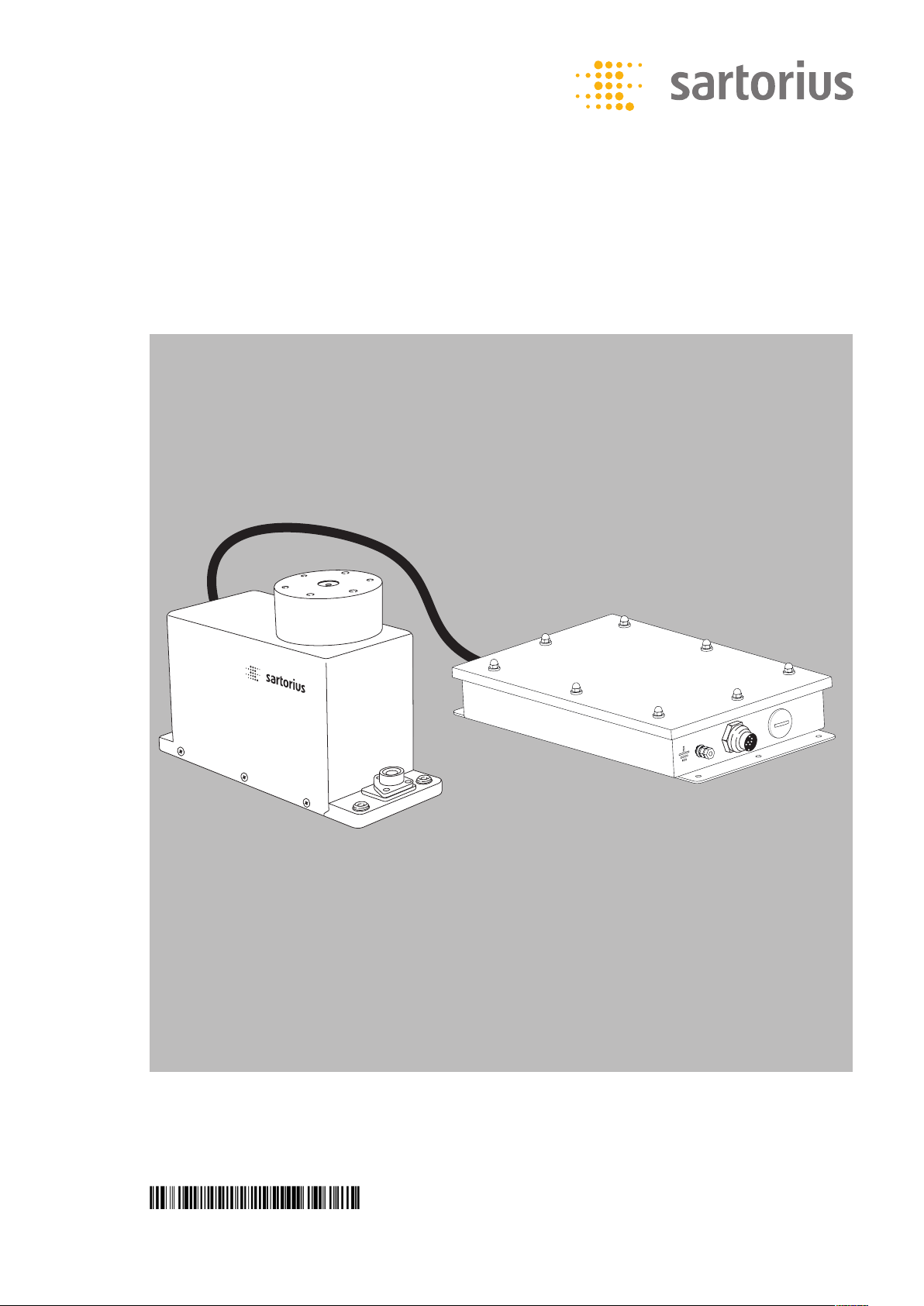
System Description
− The product is comprised of two
components:
− Compact weigh cell that can be affixed
to a smooth, even surface
− Electronics module
− These compact weigh cells can be used
to determine weights within restricted
space.
− The weigh cells have been developed for
− Installation in measuring devices and
production machinery
− High-precision weighing within limited
space
− Precise weight determination on active
production lines
Safety Precautions
− The weigh cell meets the requirements
for Group II, Category 2 equipment in
accordance with EC Directive 94/9/EC
and bears the designation h II 2G Ex
ib IIC T4 Gb and II 2D Ex ib IIIB T80°C
Db in accordance with FM EC typeexamination certificate FM 15ATEX0013X.
− Furthermore, the weigh cell meets
the EC Directives for electromagnetic
compatibility (see the Declaration of
Conformity). Improper use or handling,
however, can result in damage and/or
injury.
− The weigh cell may be used in Zone 1,
2, 21 or 22 hazardous areas or Class 1,
Division 1 or 2 hazardous locations (gas
and dust explosion hazards). Please
make sure the currently valid regulations and guidelines for installing
equipment in the hazardous areas/locations listed above (e.g., EN60079-14)
are strictly observed. Whether the
equipment can be used in a given area
containing potentially explosive agents
must be checked on a case-by-case
basis.
− That way you will prevent damage to
the device.
− These installation instructions describe
only the technological specifications of
the weigh cell and the conditions that
must be observed during installation.
− Read these installation instructions
thoroughly before using your weigh
cell. The weigh cell can be operated
indoors or outdoors.
Any incoming inspection, alterations to the equipment or instal-
lation work that does not conform to the instructions in this manual will
result in forfeiture of all claims under the
manufacturer’s warranty.
If you use electrical equipment
in installations and under ambi-
ent conditions requiring higher
safety standards, you must comply with
the provisions as specified in the applicable
regulations for installation in your country.
t Have the equipment inspected at
appropriate intervals for correct functioning and safety by a trained technician.
Page 3
Always make sure the weigh cell
is disconnected from AC power
before performing any installation, cleaning, maintenance or repair work.
If the equipment housing is opened by
anyone other than persons authorized by
Sartorius, all claims under the manufacturer’s warranty are forfeited. Use only original Sartorius spare parts.
Disconnecting equipotential
bonding conductors is not per-
mitted.
If you see any indication that
the weigh cell cannot be oper-
ated safely (for example, due to
damage), turn off the unit and lock it in a
secure place so that it cannot be used for
the time being. Observe the relevant safety
precautions and inform personnel as
required.
The casing on all connecting
cables, as well as the casing on
wires inside the equipment
housing, is made of PVC. Chemicals that
corrode these materials must be kept away
from these cables.
Make sure the weighing instru-
ment is not exposed to sub-
stances that release chlorine ions
at the place of use. If such exposure
cannot be ruled out, the operator is
responsible for establishing and observing
appropriate safety precautions, to
be checked at regular intervals for continued effectiveness.
The weigh cell may be used and
operated by qualified personnel
only. The permissible use of the
equipment is defined by the equipment
specifications and the relevant safety regulations. Operating the weigh cell beyond
the specifications listed in the typeapproval certificate is not permitted, and
is considered use of the equipment for
other than its intended purpose. All restrictions listed in the type-examination certificate must be strictly observed.
t Once the weigh cell has been installed,
it must be checked to ensure:
− Observance of the guidelines and stand-
ards for using electrical equipment
− Electromagnetic compatibility of the
entire device
− Compliance with mandatory safety reg-
ulations.
− Installation in a Zone 1, 2, 21 or 22
hazardous area or Class 1, Division 1 or
2 hazardous location must be performed by a trained technician who is
familiar with the assembly and operation of the equipment, as well as with
the procedure for putting the system
into operation. Furthermore, the trained
technician must have the required qualifications and must be familiar with the
relevant guidelines and regulations.
If you need assistance, contact the
system installer, your Sartorius dealer or
the Sartorius Service Center.
Any installation work that does not
conform to the instructions in this
manual will result in forfeiture of
all claims under the manufacturer’s
warranty. Be sure to observe all restrictions listed in the type-examination
certificate. Operating the weigh cell
beyond the limits imposed by these
restrictions is not permitted and is considered use of the equipment for other
than its intended purpose.
Always make sure the weigh cell
is disconnected from AC power
before performing any installa-
tion, cleaning, maintenance or repair work.
The electronics module and the
optional YAC01NX display and
control unit may not be opened.
The weigh cell may be opened only by
authorized service technicians who have
been trained by Sartorius and who follow
Sartorius’ standard operating procedures
for maintenance and repair work.
Avoid interchanging weigh cells
and electronics modules.
Connect the parts that fit
together, ensuring that the serial numbers
match.
Be sure to unplug the system
from AC power before connecting or disconnecting any cables.
If you are using the optional
YAC01NX display and control
unit, it must be installed a way
that limits the risk of mechanical damage.
Never open the display and
control unit.
If there is visible damage to the
components: disconnect the
equipment from AC power and
replace the weigh cell along with the electronics module.
If you use cables purchased from
another manufacturer in the
non-hazardous area/location,
check the pin assignments. Before connecting the cable to Sartorius equipment,
check the pin assignments in the cable
against those specified by Sartorius and
disconnect any wires that are assigned
differently. The operator shall be solely
responsible for any damage or injuries that
occur when using cables not supplied by
Sartorius. On request, Sartorius will provide
information on the minimum operating
specifications (in accordance with the
Standards for defined immunity to interference).
When using the weigh cell in
hazardous areas/locations, make
sure there is no current or voltage in the equipment before connecting or
disconnecting current-carrying cables to or
from the weigh cell. Disconnect the weigh
cell from AC power before connecting or
disconnecting cables.
Avoid exposing the weigh cell to static
electricity.
All components of the system
must be grounded, including
any draft shields used. Be sure
to connect an equipotential bonding
conductor.
Do not expose the weigh cell
unnecessarily to extreme tem-
peratures, aggressive chemical
vapors, moisture, temperature fluctuations
or vibrations. The permissible operating
temperature range during operation is
+5°C to +40°C.
− If any problems arise with the weigh
cell that require service, please contact
your local Sartorius dealer.
Hotline
§ If you have technical questions about
the construction, specifications or
installation of this weigh cell, just call
or fax your local Sartorius office.
For the address, please visit our Internet
website at: www.sartorius. com
3
Page 4
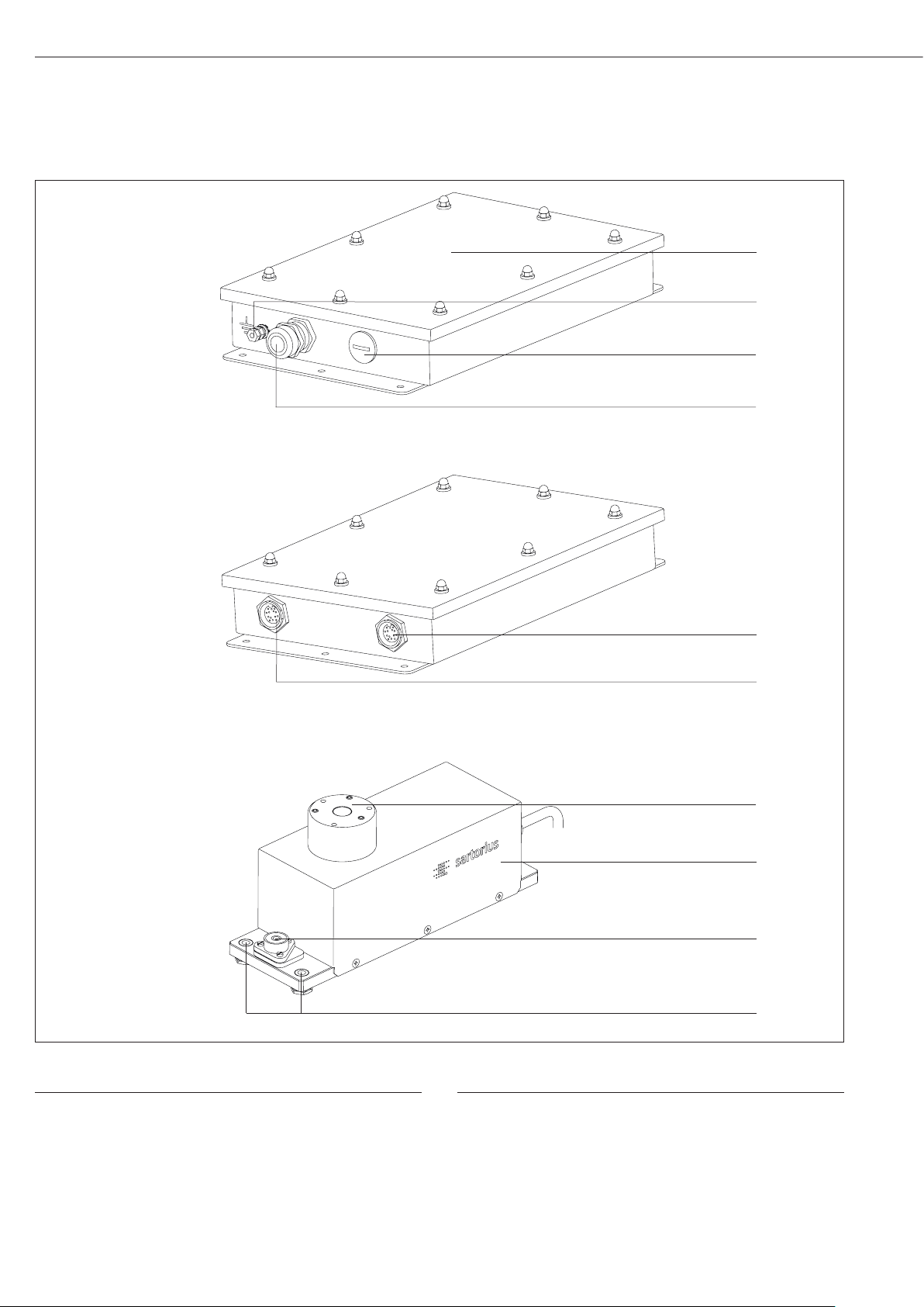
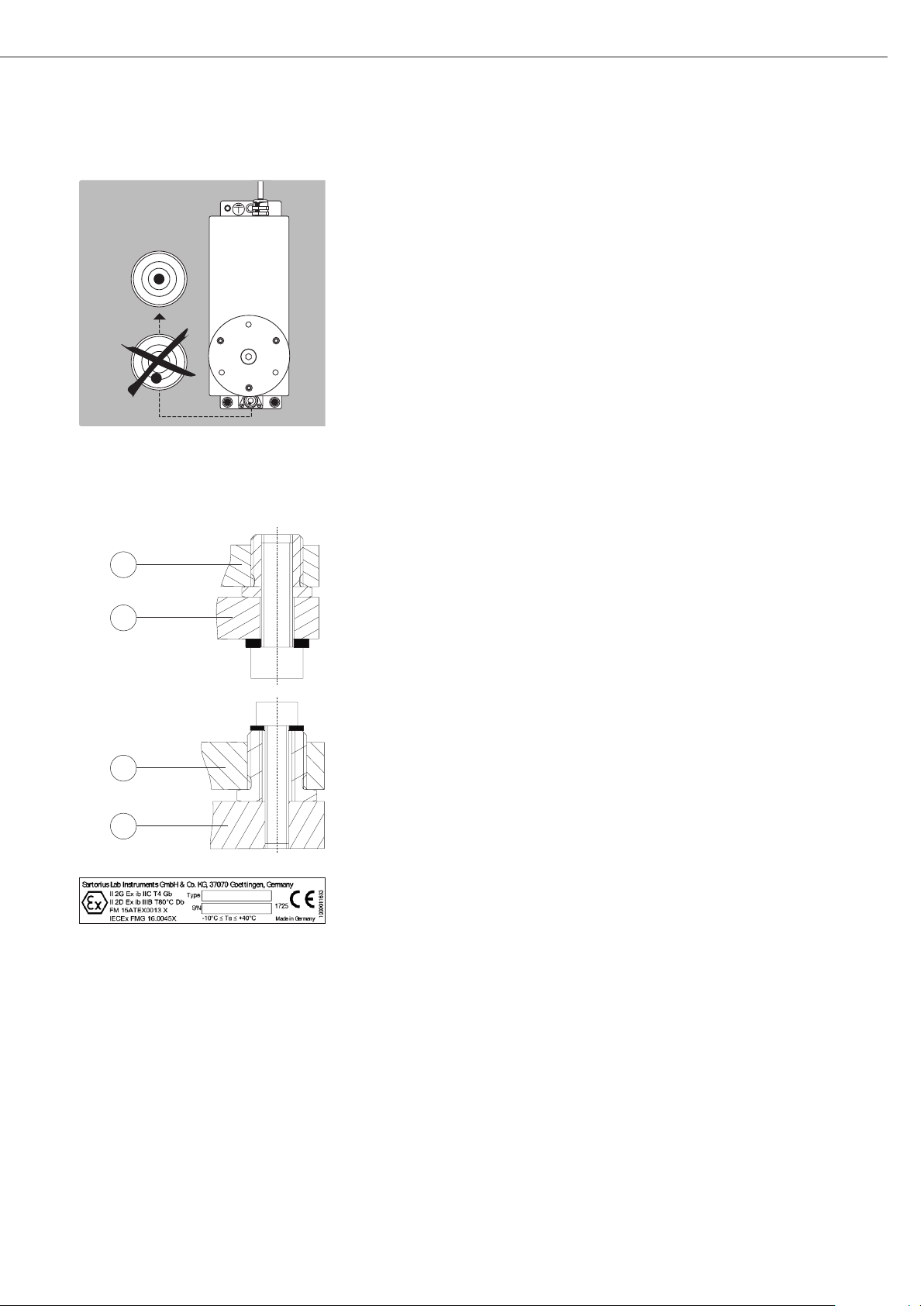
General View of the Equipment
1
2
3
4
Pos. Designation
1 Electronics module
2 Read these installation instructions thoroughly before using
your weigh cell.
3 Socket for connecting an optional display and control unit
4 Connection for weigh cell
5 Connection for optional Zener barrier
5
6
7
8
9
10
Pos. Designation
6 DC jack
7 Load receptor
8 Weigh cell
9 Level indicator
10 Threaded hole (M6) for mounting the weigh cell
4
Page 5
Installation
The weigh cells are available in various
versions. If you have ordered special
options, the weigh cells are equipped
with the specified features at the factory.
Storage and Shipping Conditions
– Once the equipment has been removed
from the packaging, it may lose accuracy if subjected to strong vibration.
Excessively strong vibration may compromise the safety of the equipment.
– Do not expose the equipment unneces-
sarily to extreme temperatures, moisture, shocks or vibration.
$ It is a good idea to save the box and all
parts of the packaging until you have
successfully installed your equipment.
Only the original packaging provides
the best protection for shipment.
$ Before packing your equipment, unplug
all connected cables to prevent damage.
$ Do not expose the equipment to
gravitational acceleration in excess of
0 300 m/s
ment is installed on the load receptor
that enables it to withstand this force).
Incoming Inspection
The customer shall inspect the product
and packaging immediately upon delivery for proper functioning, completeness, and absence of defects. This is to
be performed in an incoming inspection
within 10 days of delivery of the product. The incoming inspection must take
place before the equipment is installed.
Any obvious defects, errors, or incorrect
delivery must be reported in writing.
Defects detected at a later date must
be reported in writing immediately
upon detection.
Be sure to perform the following as part
of the incoming inspection:
– We recommend performing a repeata-
bility test using an auxiliary draft shield
to make sure the weigh cells were not
damaged in transport. You can use the
“Sartorius CAS-Suite” software or the
optional YAC01NX display and control
unit as an aid for this test.
2
(unless additional equip-
Equipment Supplied
– Weigh cell
– Electronics module
– Installation instructions (this document)
– Special accessories as listed on the bill
of delivery, if ordered, or in accordance
with specific arrangement.
Ambient Conditions
The equipment is designed to provide
reliable results under normal ambient
conditions. If you have any questions
or difficulties when developing your
weighing system, please contact the
specialists at Sartorius. When designing
and setting up your weighing system,
please observe the following so that
you will be able to work with added
speed and accuracy:
– Avoid exposing the equipment to the
effects of extremely high temperatures;
for example, caused by other electronic
components, heaters or direct sunlight.
– Protect the equipment from drafts that
come from open windows or doors.
– Avoid exposing the equipment to exces-
sive vibrations during weighing; for
example, caused by motors or valves.
– Protect the equipment from aggressive
chemical vapors.
Switch the system to the standby mode
when not in use.
Conditioning the Equipment:
Moisture in the air can condense on the
surface of a cold weighing instrument
or other device whenever it is moved
to a substantially warmer place. If you
transfer the equipment to a warmer
area, make sure to condition it for
about 2 hours at room temperature,
leaving it unplugged from AC power.
Components Attached to the Load
Receptor
– Components that are attached to the
load receptor can adversely affect the
way the weigh cell functions. The user
is responsible for how the series is used
and the specifications achieved for the
entire system. Your specifications may
differ from those listed in the section
entitled “Specifications.”
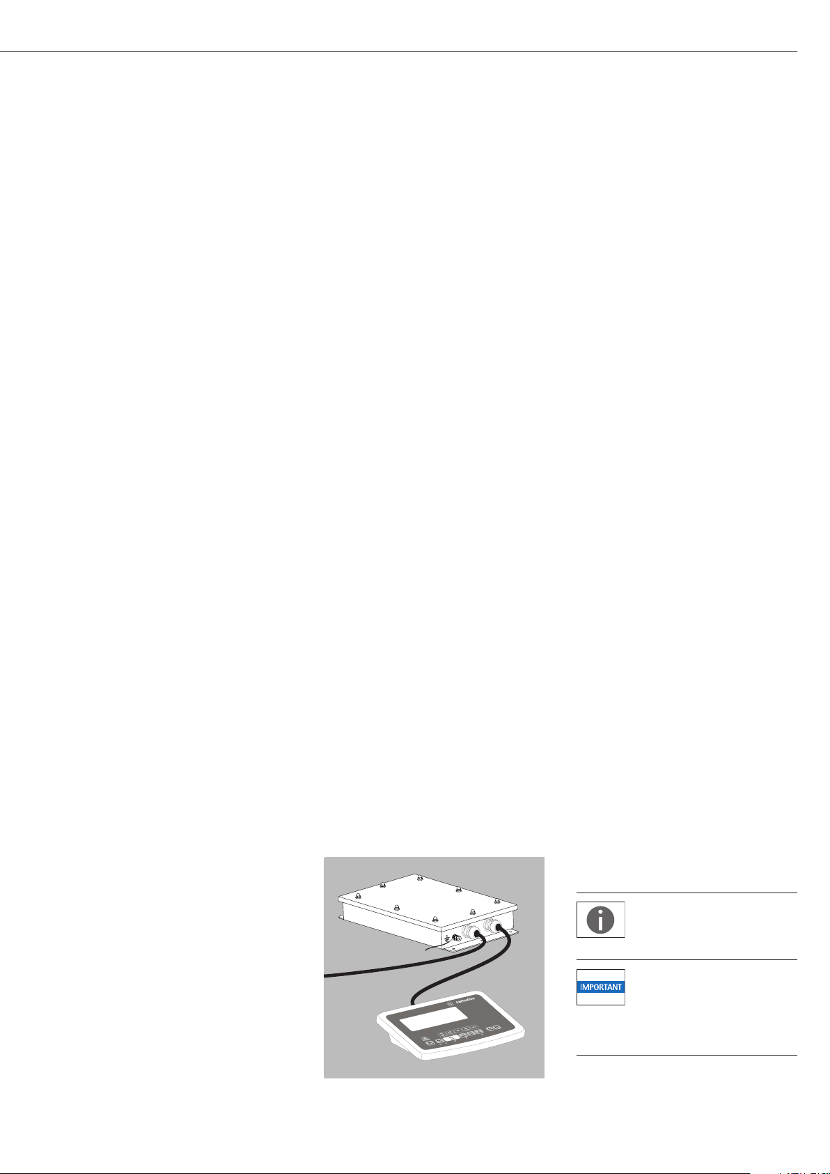
Connecting an Optional YAC01NX Display and Control Unit
The display and control unit can
only be connected if specified
directly at the time the order is
placed.
Protect the YAC01NX display
and control unit from mechani-
cal damage. If you discover that
the equipment has been damaged, disconnect it from AC power and remove it from
service.
5
Page 6
YPSC01-Z ..
Conditions for Installation
Before putting the equipment into operation, it is important to
make sure that the power cord on the associated power supply is
correctly connected to the power outlet (mains supply). All equipment must be connected to the equipotential bonding conductor
by connecting the grounding cable (not included in delivery) to the
grounding terminals provided for this purpose on each device.
The dimensions of the grounding cable are specified in national
regulations for electrical installations. Installation must be performed by a trained technician in accordance with national regulations and acknowledged technological standards.
Use only cabling and extensions approved by Sartorius, as these are
made in accordance with the restrictions on permissible cable lengths
imposed by both the capacitance and inductivity values and the
requirements for electromagnetic compatibility (see the EC TypeExamination Certificate).
Before putting the weighing system into operation for the first
time, make sure there is no hazard of explosion present at the place
of installation. If there is any indication that the equipment does
not function properly (e.g., display remains blank or is not backlit)
due to damage during transport:
– disconnect the equipment from power and
– notify your nearest Sartorius Service Center.
The weigh cell specifications for Ui, Li, Pi, Ta, temperature class,
Ci, and Li are listed in the EC type-examination certificate.
This certificate also specifies the display and control unit models
that can be used with these weigh cells.
The explosion-protected weighing system must be installed in
accordance with acknowledged rules of engineering. These include
national and international laws and regulations (such as VbF,
EX-RL, DIN EN 60079-14, DIN VDE 0166, DIN VDE 0100, DIN VDE
0101, and DIN VDE 0800).
In particular, the conditions described under Item 17 of the KEMA
EC type-examination certificate, “Special Conditions for Safe Use,”
must be observed. Furthermore, national regulations for accident
prevention and environmental protection must be observed at all
times.
Before you operate your weigh cell in a hazardous area/location,
it must be inspected either by a certified electrician or under the
guidance and supervision of a certified electrician to make sure that
the weigh cell complies with the applicable regulations. Determine
whether your weigh cell must be reported to the technical inspection authorities (such as the trade board) in your country. The system
must also be inspected during operation. The system should be
inspected at intervals which allow for early detection of the faults
that occur as a result of normal wear and tear, so that they can
be corrected before damage is caused. In any case, inspection must
be performed at least every 3 years. Other conditions and standards
that regulate the installation and operation of the equipment and
are applicable in your country must be met as well. When performing inspections, generally acknowledged rules of engineering relevant to these conditions must also be applied. If the unit housing
is opened by anyone other than persons authorized by Sartorius,
or if the equipment is installed or operated incorrectly, this will
result in forfeiture of the approval for use in the stated hazardous
area(s)/location(s) and of all claims under the manufacturer’s
warranty.
6
Page 7
t Connecting an Equipotential Bonding Conductor (Grounding)
− If the weigh cell is in a hazardous area/location, it must be grounded (i.e., an equipoten-
tial bonding conductor must be connected). This connection should be made by
a trained technician. The weigh cell is equipped with a connector for the grounding conductor. The position is marked by the symbol shown here, indicating the grounding connection.
Use a stainless steel screw (M6 thread) to connect the grounding conductor.
We recommend using a tooth lock washer to prevent the screw from coming loose.
The wire used for the grounding conductor should have a cross-sectional diameter of at
least 4 mm
2
, with a suitable ring lug attached.
The grounding cable must be installed in such a way that it is not under mechanical
stress and so the screw will not become loose. Connect all equipment, including peripheral devices, to the equipotential bonding conductor.
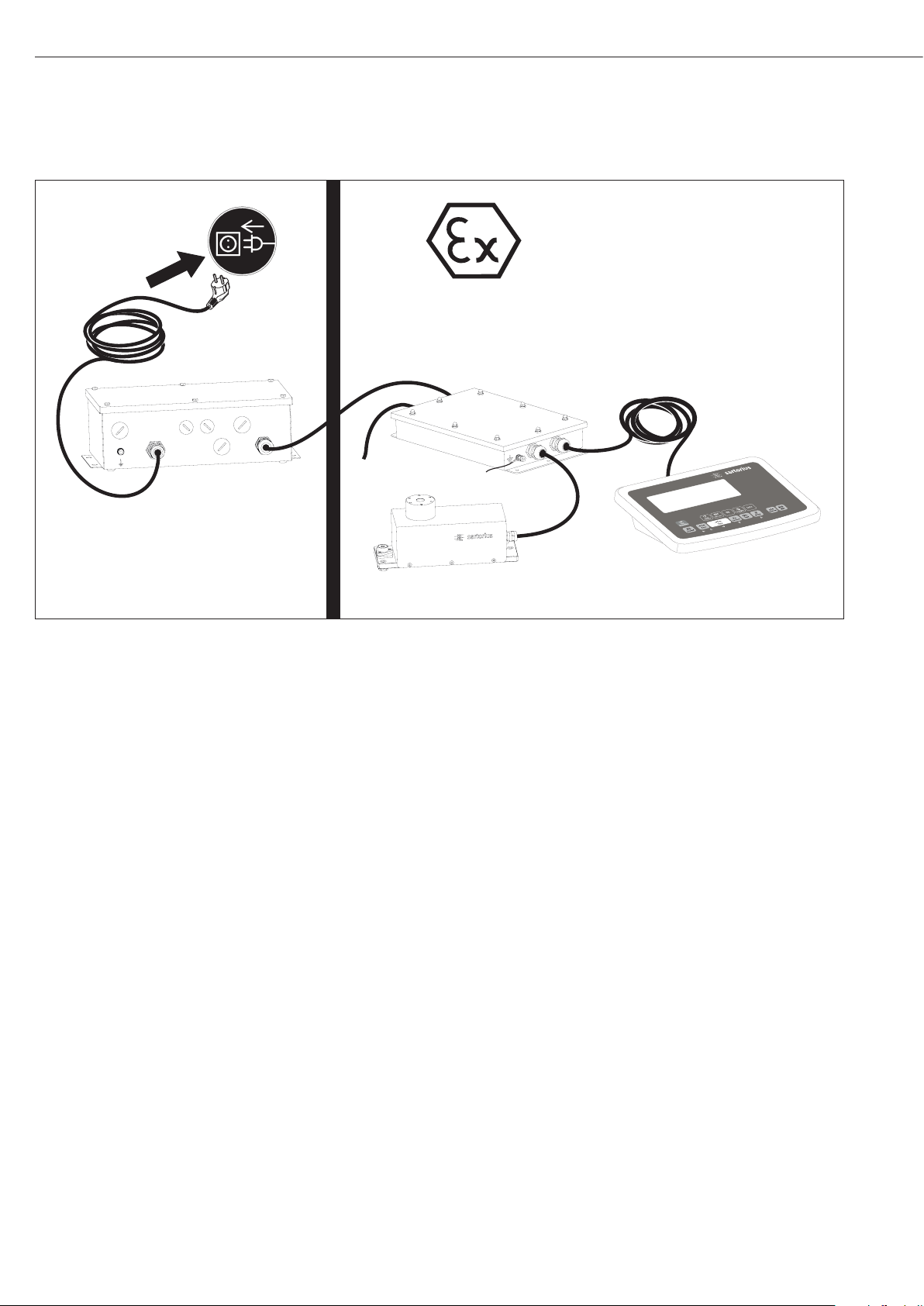
Connecting the Weigh Cell to AC Power
t Before putting the weigh cell into operation, make sure that the power cable is
correctly connected to the electrical outlet; it is especially important to make sure
the grounding cable is attached to the housing of the power supply. All devices used
must be connected to the equipotential bonding conductor via the retainers provided on
each device. Installation must be carried out by a certified electrician according to the
valid standards of technology.
Before putting the equipment into operation for the first time, make sure that the
area of installation is not hazardous. If the equipment shows any signs of mal-
function as a result of damage during shipment (display remains blank, display
not backlit even with a weight readout, weight value not repeatable, readout does not
stabilize, etc.), disconnect the equipment from AC power and contact a Sartorius service
technician.
t YPSC01-X: flameproof power supply:
− Lay both cables in a manner that is secure and protected.
− Flexible installation of cables with threaded fasteners can be carried out on request.
t Check the voltage rating and the plug design.
− If they do not match the rating or standard you use, contact your Sartorius office or dealer.
− Use only original Sartorius power supplies:
− YPC01-Z... (for use outside hazardous areas/locations)
− YPC01-X (for use within hazardous areas/locations)
To operate the weigh cell in a hazardous area or location, please comply with the
following:
– Currently valid standards and regulations for installation of explosion-protected
equipment in such areas
–
Installations in Zone 1 must be carried out and checked by a certified electrician.
t Plug the female connector of the blue intrinsically safe power supply cable into the
socket on the weigh cell. Secure this connection by tightening the knurled collar.
Be sure to connect the power supply to the electronics module before plugging
the equipment in to AC power.
Install the power cable so that it is protected from damage.
The intrinsically safe connector for the power cable (primary side) is not part of
the standard equipment supplied (open cable ends).
Connecting Electronic Peripheral Devices
Make absolutely sure to unplug the weigh cell from AC power before you connect
or disconnect a peripheral device (display and control unit or PC) to or from the
interface port.
7
Page 8
Warmup Time
The amount of warmup time required depends in part on the system in which the
weigh cell is installed. To deliver exact results, the weigh cell must warm up for at
least 30 minutes after it is connected to power for the first time. Only after this
time will the device have reached the required operating temperature.
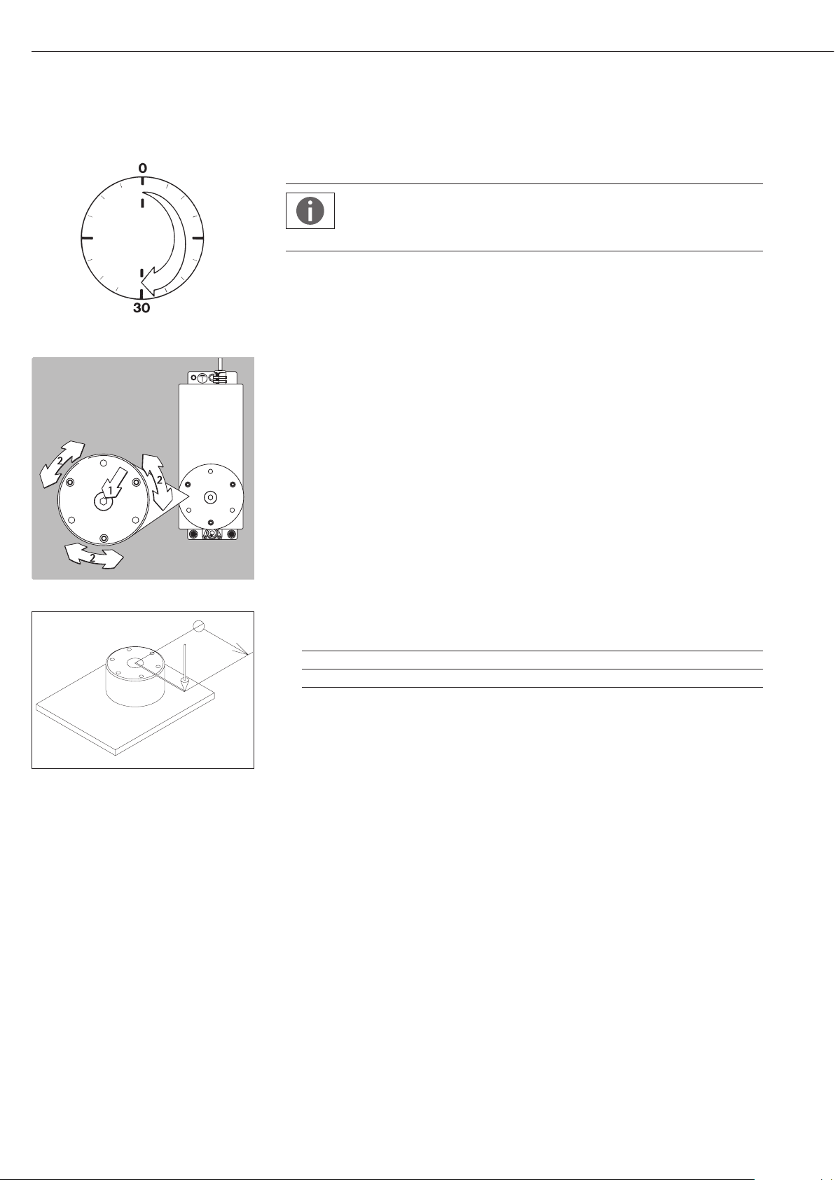
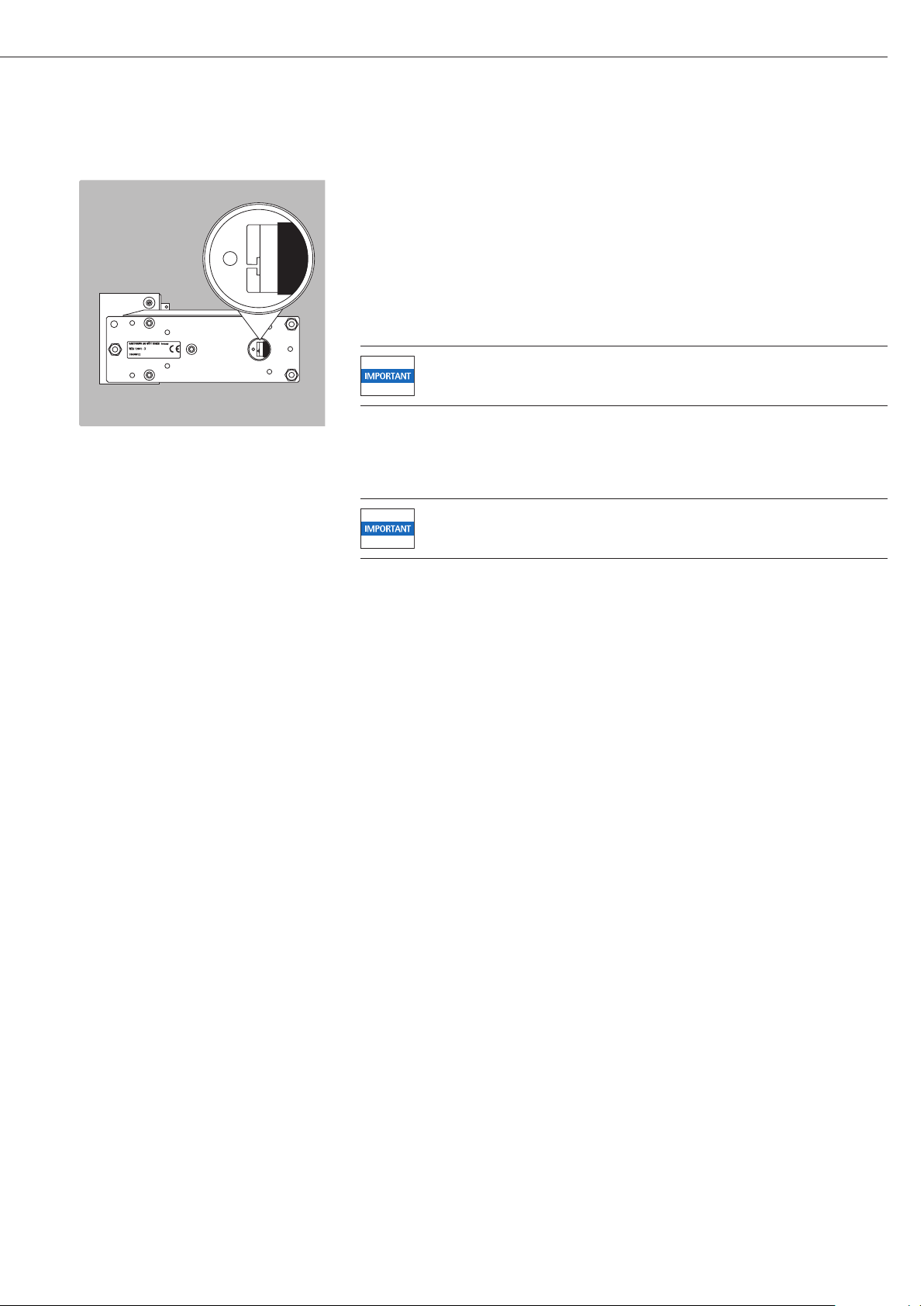
Leveling the Load Receptor and User-Specific Transducer
t Remove the (S1) screw.
t Use the (S2) screws to radially position and level the load receptor (minor height adjust-
ment also possible).
t Attach the (S1) screw to affix the load receptor and tighten it as indicated in the table
below listing the torque values.
t Attach any user-specific transducer to the threaded fastener (S3) on the load receptor and
tighten it as indicated in the table below: Maximum load on load receptor.
t The user-specific transducer must be rigid and securely connected to the load receptor.
R
G
G = Load
R = Distance from the center of the pan
M
= G . R
eck
Maximum load on load receptor:
Model M
eck
S1 S2 S3
WZA623-NX 2.5 Nm 1 Nm 1 Nm 2 Nm
WZA6202-NX 6 Nm 4 Nm 2 Nm 4 Nm
If the load is not centered on the load receptor, the corner load moment M
exceeded, since this could lead to a defect in the weigh cell.
may not be
eck
The force “G” is comprised of the weight of the sample and the non-centric load on the
weigh cell.
The load receptors should be constructed so that they are stiff and cannot be bent or
twisted.
Example: What is the maximum permissible length of the cantilever
(on WZA623-NX in this instance)?
It is assumed that the load is connected to a cantilever that has a uniform width.
The cantilever utilizes the necessary preload of 600 grams on the WZA623-NX.
M
~ 1 R + G
eck Arm
M
= R + G
eck Last
= 6.1 N
M
= M
eck
= R (1 + G
R
(1 G
= ———————————
eck Arm
M
eck
Arm
Last
Arm
+ M
+ G
Arm
eck Last
+ G
Last
)
Last
)
R = 2.5 Nm / 12 N = 0.2 m
R = 0.2 m
G
= 9.81 m/s2 + 0.6 kg
Arm
= 5.9 N
G
= 9.81 m/s2 + 0.62 kg
Last
The maximum length that the cantilever
can be without destroying the system is
200mm. As a result of handling, other
moments can occur, which must be taken
into consideration. In general, we recommended testing first because there can
be undesired repercussions. Drafts can
influence results as well.
8
Page 9
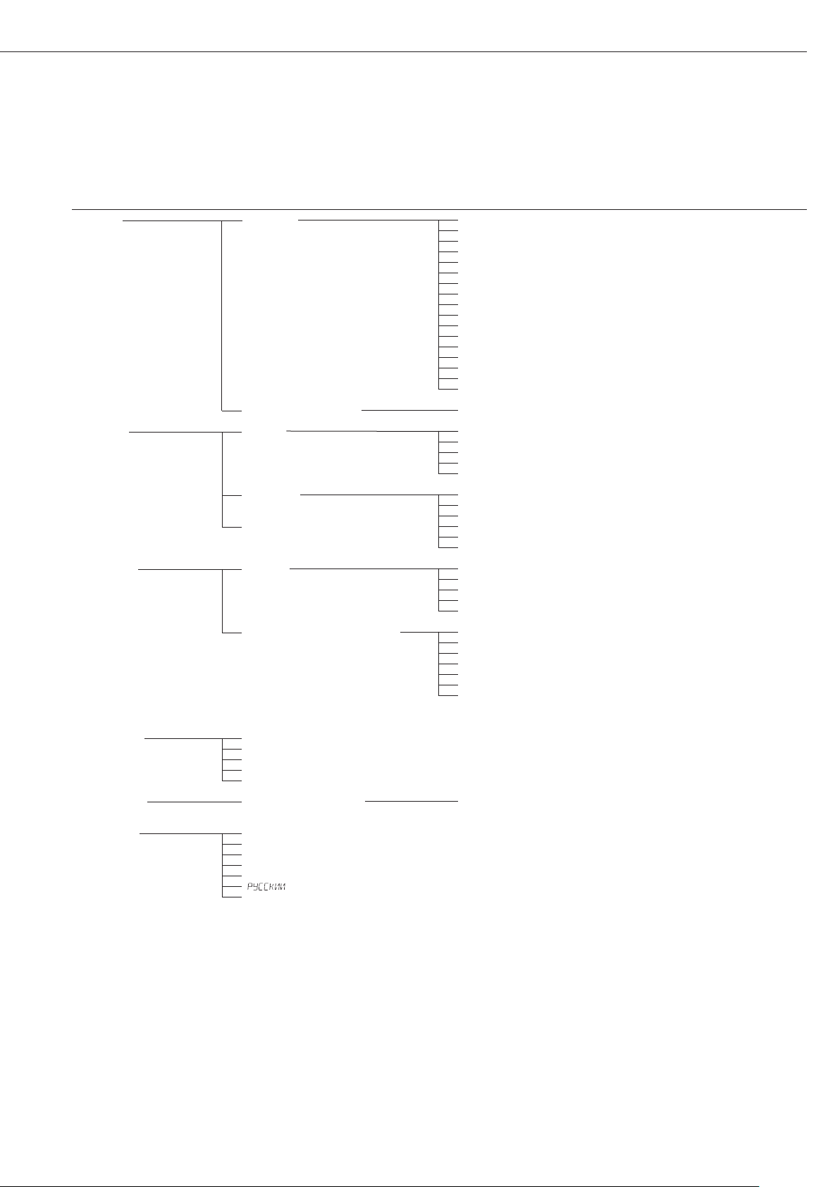
Leveling the Weigh Cell in a Portable Weighing System (Leveling Feet Optional)
Purpose:
– To compensate for uneven areas at the place of installation
– To ensure that the weigh cell is placed in a perfectly horizontal position for consistently
reproducible weighing results
– Always level the weigh cell again any time after it has been moved to a different location.
§ Adjust the leveling feet until the air bubble is centered within the circle on the level
indicator.
Permanently Installed Weigh Cells
– Adjust the weigh cell after it has been installed in the system in its permanent location
(see next page).
The weigh cell must be leveled again any time the location or position of the weighing
system is changed.
– For optimum operation, install the weigh cell in a horizontal position.
1
1) Bottom plate of the weighing cell
2) Fastening frame of the system
2
1
§ Fastening with M6 screws:
Connection to the threaded fasteners on the weigh cell (1): torque: 2.5 Nm
§ Fastening with M4 screws:
Connection to the threaded fasteners of a user-specific frame (2).
2
Device-Specific Information: Coding of the Serial Number
The year that the device was manufactured is coded in the serial number.
The format is as follows:
YMM x x x x x
Y Year
3 2014–2020 6 2035–2041
4 2021–2027 7 2042–2048
5 2028–2034 8 2049–2055
9 2056–2062
Each number in the Y column represents a group of seven years during which the device
was manufactured. Within each group of years, the months of the year (M M) advance
chronologically from 13 upwards.
Year: 2015 2016 2017 ...
MM: 25-36 37-48 49-60 ...
Example:
328xxxxx (April 2015)
xxxxx is a consecutive number that is counted upward after being reset each month.
9
Page 10

Operation
Notes on Analytical
Weighing with Weigh Cells
Handling of Samples and Containers
Samples should be acclimatized to the
temperature of the weigh cell to avoid
negative effects on results, such as
measurement errors and fluctuations
caused by air buoyancy resulting from
convection currents across the surface
of the sample.
These negative effects increase as the
volume and/or surface area of the sample increases. For this reason, the size of
the container should be appropriate for
the sample.
Samples and containers should not be
touched by the operator’s hands, as the
hygroscopic effect of fingerprints and
the effect of the hand’s temperature
can influence the measurement results.
Samples must be applied very carefully,
whether manually (using forceps) or
automatically (by a robot or filling
system).
When designing a draft shield device,
steps must be taken to keep the
increase in temperature within the
weighing chamber to a minimum
(e.g., using a bypass).
Weighing Electrostatically Charged
Samples or Containers
If a sample or container is electrostatically charged, significant errors may
result during weighing. Materials with
low conductivity, such as glass, plastic
or filters, are particularly susceptible to
static electricity (resulting, e.g., from
friction) because the weighing pan can
discharge the static electricity only very
slowly.
The result is a force action between
the charge on the sample and the permanently installed parts of the weigh
cell. This causes the readout to fluctuate constantly.
Ionization can be applied to make the
air around the sample conductive. This
allows the charge to be compensated
through the air, or discharged through
the ground (grounded).
The area around the weigh cell can
also contain charges that negatively
affect the accuracy of weighing results.
Appropriate steps taken in the design
of a draft shield device can counteract
such effects. In the process, be sure to
install devices that are suitable for use
in the particular hazardous zones.
Weighing Magnetic or Magnetizable
Samples
For technical reasons, the use of magnetizable materials in the manufacture
of weigh cells is unavoidable, primarily
because the operating principle of highresolution weigh cells is based on
compensation of the load through
magnetic forces.
When weighing magnetic or magnetizable samples or containers, interaction
between the sample or container and
certain parts inside the weigh cell may
have a distorting effect on the weighing
results.
To keep such effects to a minimum,
we recommend increasing the distance
between the sample/container and the
weighing system using a non-magnetic
material. The force is reduced quadratically with the increase in distance.
Magnetizable or magnetized samples
and the weigh cell itself interact with
magnetic fields and magnetizable or
magnetized parts in the area surrounding the weighing system. The system
can be shielded from external magnetic
fields to some extent using (soft magnetic) plates.
10
Calibration/Adjustment
Calibration/adjustment can be per-
formed as follows:
– Using control commands sent by the
CAS-Suite configuration software from
Sartorius, installed on a computer
(see page 18 for the commands)
or
− Using the optional YAC01NX display
and control unit
Page 11
Below-Cell Weighing
A port for a below-cell weighing hanger is located on the bottom of the weigh cell.
t Remove the cover plate.
− Threaded fastener for hook: M3
Overload protection
− Standard feature on the WZA623-NX model
Models WZA6202-NX:
No overload protection provided
t Carefully install the special hook: maximum torque: 0.75 Nm
− If necessary, install a shield for protection against drafts.
Protection rating: only IP22 is provided when the cover plate for the below-cell
weighing port has been removed.
11
Page 12

Factory Settings (Setup)
Purpose
− The weigh cell is configured at the fac-
tory. The factory settings can be
adapted to individual requirements by
editing the “Setup” menu.
Features
Parameters are combined into the
following groups
(1st menu level):
1. Setup: Balance parameters
2. Device parameters
3. Data output
4. Application program
5. Input
6. Information
7. Language setting
1
)
Factory Settings for the Parameters
Factory-set configurations are marked
with “o.” Customer-specific settings
can be configured on request.
Preparation
The following operating menu
functions can be carried out using
the Sartorius CAS-Suite configuration
software installed on a PC:
– Read
– Change
– Print
– Save
or
With one of the optional YAC01NX
control units
1
) Detailed instructions on the available
application programs can be found
in the operating instructions for the
Cubis Series, MSE Models, which can be
downloaded online:
Go to www.sartorius.com –
Service Center ➝ Downloads.
12
Page 13
Menu Structure (Overview)
Level 1 Level 2 Level 3 Menu level info
1) Setup Bal.Scal. Ambient Ambient conditions 1. 1. 1.
(Weigh cell functions) app.filt. Application filter 1. 1. 2.
Stab.rng. Stability range 1. 1. 3.
Stab.dly Stability delay 1. 1. 4.
Taring Taring
Autozer. Auto zero 1. 1. 6.
Wt.Unit Basic weight unit 1. 1. 7.
Display Display accuracy
Cal./adj. Function of the C key 1. 1. 9.
Cal.routine Calibration/adjustment routine 1. 1. 10.
Zerorng. Zero range 1. 1. 11.
Zero.on Zero at power on 1. 1. 12.
On.tare Tare/zero at power on 1. 1. 13.
Cyc.rate Output rate 1. 1. 14.
isocal Auto calibration/adjustment 1. 1. 15.
EXT.Cal. External adjustment 1. 1. 16.
cal.unit Weight unit for calibration
gen.serv. General service men.reset Factory settings 1. 9. 1.
2) Device extras menu Menu read only/can edit 2. 1. 1.
(Additional functions) Signal Acoustic signal 2. 1. 2.
Keys (Keypad) 2. 1. 3.
Ext.Key External switch function 2. 1. 4.
Onmode Power-on mode 2. 1. 6.
Peripher. dat.rec. Communication mode 2. 2. 1./2. 3. 1.
(25-pin “Peripherals” interface) Baud Baud rate 2. 2. 2./2. 3. 2.
parity Parity 2. 2. 3./2. 3. 3.
pc-usb (USB port “PC”) Stopbit Number of stop bits 2. 2. 4./2. 3. 4.
Handshk. Handshake mode 2. 2. 5./2. 3. 5.
databit Number of data bits 2. 2. 6./2. 3. 6.
3) Dataout com.sbi com.out Communications output 3. 1. 1.
(Data output) (PC communication) Stop Stop automatic output 3. 1. 2.
Aut.Cycl. Time-dependent automatic data output 3. 1. 3.
Format (Line format) 3. 1. 4.
Auto.Tare Auto taring after data output 3. 1. 5.
Print.para Parameters for printing Res. Print resolution (manual/automatic) 3. 2. 1.
Format Line format for printout 3. 2. 2.
Prt.Init. Printout of appl. parameters 3. 2. 3.
GLP ISO/GLP-compliant printout 3. 2. 4.
tar./prt. Tare bal./scale after ind. print 3. 2. 5.
time: 12h/24h 3. 2. 6.
date Date format 3. 2. 7.
4) Applic.ation programs
5) Input Input ID. ID input; max. 7 characters 5. 1.
Date Set date 5. 2.
Time Set time 5. 3.
Password Password entry (for service) 5. 4.
Cal.wt. Enter weight value 5. 5.
6) Information Version, Ser.no., model, Display of software version, serial no., model 6. 1. to 6. 6.
lobs, kdcvers, DR.Shield, if OPT.MOD
7) Language English English (factory setting) 7. 1.
Deutsch German 7. 2.
franc. French 7. 3.
ital. Italian 7. 4.
Espanol Spanish 7. 5.
Polski Polish 7. 7.
1
)
Russian 7. 6.
1
) 1. 1. 5.
1
) 1. 1. 8.
1
) 1. 1. 17.
1
) Detailed instructions on the available application programs can be found in the operating instructions for the „Signum series,“ which can be downloaded online:
Go to www.sartorius.com – Service Center Downloads.
13
Page 14
Parameter Settings: Overview
ο = factory setting;√ = user-defined setting
Info about
Level 1 Level 2 Level 3 Level 4 menu level
1) Setup Bal.Scal. Ambient Ambient conditions V.Stable Very stable 1. 1.1. 1
Balance (filter adjustment) ο Stable Stable 1. 1.1. 2
parameters unstabl Unstable 1. 1.1. 3
v.unstbl. Very unstable 1. 1.1. 4
App.Filt. Application filter ο Final.rd. Final readout mode 1. 1.2. 1
Filling Filling mode 1. 1.2. 2
Reduc. Reduced 1. 1.2. 3
Off Off 1. 1.2. 4
Stab.rng. Stability range Max.acc. Maximum accuracy (1⁄4 digit) 1. 1.3. 1
V.acc. Very accurate (1⁄2 digit) 1. 1.3. 2
Acc. Accurate (1 digit) 1. 1.3. 3
ο Fast Fast (2 digits) 1. 1.3. 4
V.fast Very fast (4 digits) 1. 1.3. 5
Max.fast Maximum speed (8 digits) 1. 1.3. 6
St.del. Stability delay No No delay 1. 1.4. 1
ο Short Short delay 1. 1.4. 2
Averg. Average delay 1. 1.4. 3
Long Long delay 1. 1.4. 4
Tare Tare wiostb. Without stability 1. 1.5. 1
ο Wistb. After stability 1. 1.5. 2
Atstab. At stability 1. 1.5. 3
Aut.zero ο on Automatic zeroing on 1. 1.6. 1
Auto zero off Automatic zeroing off 1. 1.6. 2
WT.UNIT For list of units, see 1. 1.7. 1
Basic weight unit “Toggling between weight units” to
1. 1.7.24
Disp.dig. ο all Display all digits 1. 1.8. 1
Display accuracy lp.on.off Last digit after load change 1. 1.8. 2
Increment of measured values one level lower 1. 1.8. 3
Increment of measured values two levels lower 1. 1.8. 4
Increment of measured values three levels lower 1. 1.8. 5
Incrm.1 Last digit single increment 1. 1.8. 6
Minus 1 Reduced by one digit 1. 1. 8. 7
Resolution by a factor of 10 1. 1. 8.14
Cal./Adj. EXT.Cal. External calibr./adjustment with factory-set weight 1. 1.9. 1
Function of C key cal.e.usr. External calibr./adjustment with user-defined weight 1. 1.9. 3
ο cal.int. Internal calibr./adjustment 1. 1.9. 4
lin.int. Internal linearization (on analytical balances only) 1. 1.9. 5
lin.ext. External linearization with factory-set weights 1. 1.9. 6
lin.usr. External linearization with user-defined weights 1. 1.9. 7
set.prel. Set the preload 1. 1.9. 8
clr.prel. Delete the preload 1. 1.9. 9
blocked C locked 1. 1.9.10
Select Select 1. 1.9.12
set.ext.w. Determine ext. calibration weight for cal.e.usr 1. 1.9.17
Determine internal weight 1. 1.9.18
Cal./Adj. Calibration/adjustment ο Sequence Sequence adjustment 1. 1.10. 1
CAL/adj. Adjustment as needed 1. 1.10. 2
Zerorng. Zero range 1perc. 1 percent of max. load 1. 1.11. 1
ο 2perc. 2 percent of max. load 1. 1.11. 2
5perc. 5 percent of max. load 1. 1.11. 3
10perc. 10 percent 1. 1.11. 4
default (factory-set) 1. 1.11. 5
init.zero Zero at power on ο default (factory-set) 1. 1.12. 1
2perc. Initial zero 2 percent 1. 1.12. 2
On. Tare Tare/zero at power on ο On Init. tare/zero on 1. 1.13. 1
Off Init. tare/zero off 1. 1.13. 2
5perc. 5 percent 1. 1.13. 3
10perc. 10 percent 1. 1.13. 4
20perc. 20 percent 1. 1.13. 5
50perc. 50 percent 1. 1.13. 3
100perc. 100 percent 1. 1.13. 7
cyc.rate Output rate ο normal Normal output 1. 1.14. 1
highvar. High var. output 1. 1.14. 2
slow Slow output 1. 1.14. 3
medium Medium output 1. 1.14. 4
fast Fast output 1. 1.14. 5
veryfast Very fast output 1. 1.14. 6
maximum Max. output 1. 1.14. 7
ISOcal Auto calibration/adjustment ο Off Auto cal./adj. off 1. 1.15. 1
Note Info 1. 1.15. 2
On Auto cal./adj. on 1. 1.15. 3
Ext.cal. External calibration ο free Unlocked 1. 1.16. 1
locked Locked 1. 1.16. 2
cal.unit ο Gram Grams 1. 1.17. 1
Unit for calibration weight Kilogr. Kilograms 1. 1.17. 2
Userdef. User-defined unit (factory setting: pounds) 1. 1.17. 4
gen.serv. men.Reset Menu reset Yes Restore factory settings 1. 9. 1. 1
General service (factory settings) ο No Do not restore factory settings 1. 9. 1. 2
Standard Standard settings 1. 9. 1. 3
Verifiable Verifiable settings 1. 9. 1. 4
14
Page 15
Level 1 Level 2 Level 3 Level 4 Menu level info
2) Device extras menu ο canedit Can edit 2. 1. 1. 1
(Additional Rd.only Read only 2. 1. 1. 2
functions)
Signal Acoustic signal off Acoustic signal off 2. 1. 2. 1
ο on Acoustic signal on 2. 1. 2. 2
Keys Keypad ο free Unlocked 2. 1. 3. 1
locked Locked 2. 1. 3. 2
Ext.Key ο Print P key (print) 2. 1. 4. 1
External switch function Z/Tare J key (tare) 2. 1. 4. 2
cal. C key (calibrate) 2. 1. 4. 3
cf F key (go back/exit) 2. 1. 4. 5
enter V key (enter) 2. 1. 4. 6
Dr.shield Draft shield 2. 1. 4. 9
Ionizer Ionizer 2. 1. 4. 10
appl. Application key 2. 1. 4. 11
Asterisk * key 2. 1. 4. 12
onmode off/on/sb Off/On/Standby 2. 1. 6. 1
Power-on mode off/on/SO Off/On/Auto shut-off 2. 1. 6. 2
on/sb On/Standby 2. 1. 6. 3
ο AutoOn Auto on 2. 1. 6. 4
Periphery:/PC USB:
Peripher. dat.rec. ο SBI (ASCII) 2. 2. 1. 1/2. 3. 1. 1
(25-pin “Peri- Operating mode XBPI 2. 2. 1. 2/2. 3. 1. 2
pherals” interface) Rem.displ. Remote display 2. 2. 1. 4/2. 3. 1. 4
uni.Print Universal printer 2. 2. 1. 7/2. 3. 1. 7
pc usb lab.print (Parameters for YDP10 printer) 2. 2. 1. 8/2. 3. 1. 8
(USB port for PC) OFF Interface off 2. 2. 1.10/2. 3. 1.10
Baud Baud rate 600 2. 2. 2. 3/2. 3. 2. 3
ο 1200 2. 2. 2. 4/2. 3. 2. 4
2400 2. 2. 2. 5/2. 3. 2. 5
4800 2. 2. 2. 6/2. 3. 2. 6
9600 2. 2. 2. 7/2. 3. 2. 7
19200 1) 2. 2. 2. 8/2. 3. 2. 8
38400 1) 2. 2. 2. 9/2. 3. 2. 9
57600 1) 2. 2. 2.10/2. 3. 2.10
115200 1) 2. 2. 2.11/2. 3. 2.11
1
) Only one of the two interfaces can be used.
15
Page 16

Level 1 Level 2 Level 3 Level 4 Menu level info
Periphery:/PC USB:
2) Device peripher. Parity ο Odd Odd parity 2. 2. 3. 3/2. 3. 3. 3
pc usb Parity Even Even parity 2. 2. 3. 4/2. 3. 3. 4
None No parity 2. 2. 3. 5/2. 3. 3. 5
StopBit ο 1Stop 1 stop bit 2. 2. 4. 1/2. 3. 4. 1
Number of stop bits 2Stop 2 stop bits 2. 2. 4. 2/2. 3. 4. 2
Handshk. Softw. Software 2. 2. 5. 1/2. 3. 5. 1
Handshake mode ο Hardw. Hardware 2. 2. 5. 2/2. 3. 5. 2
# None No handshake 2. 2. 5. 3/2. 3. 5. 3
DataBit 7Bits 7 data bits 2. 2. 6. 1/2. 3. 6. 1
Number of data bits ο 8Bits 8 data bits 2. 2. 6. 2/2. 3. 6. 2
3) dataout Comm.SBI COM. Output in.wio Without stability 3. 1. 1. 1
Data PC Manual/automatic ο IN. After After stability 3. 1. 1. 2
output communication IN.at At stability 3. 1. 1. 3
Auto.wio Auto without stability 3. 1. 1. 4
Aut.With Auto with stability 3. 1. 1. 5
Stop ο off Auto output off 3. 1. 2. 1
Auto output on Auto output on 3. 1. 2. 2
Aut.Cycl. ο Every 3. 1. 3. 1
Time-dependent automatic data output 2ndvalue 3. 1. 3. 2
Format Line format ο 16chars (digit not identified) 3. 1. 4. 1
22chars (digit identified) 3. 1. 4. 2
Extr.line (date, time, and weight value) 3. 1. 4. 4
Auto.Tare ο Off Auto tare off 3. 1. 5. 1
Auto taring after data output On Auto tare on 3. 1. 5. 2
Print.para res.olution Manual without Manual without stability 3. 2. 1. 1
Parameters (manual/auto) ο man.after Manual after stability 3. 2. 1. 2
for printing man.at Manual at stability 3. 2. 1. 3
auto.lc Auto at load change 3. 2. 1. 6
Format Line format for printout 16chars (digit not identified) 3. 2. 2. 1
ο 22chars (digit identified) 3. 2. 2. 2
Extr.line (date, time, and weight value) 3. 2. 2. 4
Prt.Init. Printout off Printout off 3. 2. 3. 1
of application parameters ο all Print all parameters 3. 2. 3. 2
Mainpar. Print main parameters 3. 2. 3. 3
GLP ISO/GLP- ο off Printout off 3. 2. 4. 1
compliant printout cal.adj. For calibration/adjustment only 3. 2. 4. 2
Always Printout always on 3. 2. 4. 3
tar./prt. ο off Taring off 3. 2. 5. 1
Tare bal./scale after individual print on Taring on 3. 2. 5. 2
Time ο 24h 24 h display 3. 2. 6. 1
12h 12 h display (AM/PM) 3. 2. 6. 2
Date ο dd.mmm.yy Date format 3. 2. 7. 1
mmm.dd.yy Date format 3. 2. 7. 2
# = Factory setting for “PC-USB” interface
16
Page 17

RS-232 Interface Port
Purpose
The weigh cells are equipped with
a data interface for connection to
a computer or other peripheral device.
Computer
You can connect a computer to alter,
start or monitor weigh cell functions.
Features
Type of interface: Serial interface
Operating mode: Full duplex
Standard: RS-232
Transmission rates: 600 to 115,200 baud
Parity: Space, odd, even
Character format: Start bit, 7-bit ASCII, parity 1 or 2 stop bits
Handshake mode: For 2-wire interface: software (XON/XOFF)
For 4-wire interface: hardware (CTS/DTR)
Operating mode: SBI (ASCII), XBPI*
* XBPI operating mode:
Always with 9600 baud, 8-bit, parity odd, 1 stop bit.
There are numerous additional commands for communicating with the weigh cell.
Please contact Sartorius for more information about their operation.
Protocols
For data exchange, the interfaces are configured with the following protocols:
– Printer output
– SBI (Sartorius Balance Interface): Sartorius standard protocol for output to a PC or control
unit. This simple ASCII-based protocol allows you to use ESC commands from your PC to
control the basic weighing functions.
– xBPI (eXtended Balance Processor Interface, also known as X-Bus): Binary protocol with
extended scope of commands. This protocol lets you control numerous weighing functions. For further information on this, please contact Sartorius. To use the protocols,
application software must be installed on the PC.
Synchronization
During data communication between balance and PC, messages consisting of ASCII or
binary characters are transmitted via the interface. For error-free data exchange, parameters for baud rate, parity, handshake mode, and character format must be identical for
both units. You can configure the respective settings in System Settings (menu).
In addition to these settings, data output for the balance can also be made dependent on
several conditions that are defined in the individual tasks. These conditions are described
under each of the tasks.
17
Page 18

Data Output
You can define the data output parameter so that output is activated either when a print
command is received or automatically synchronized with the display or at defined intervals
(see application programs and autoprint settings).
Data Output following Print Command The print command can be transmitted by pressing the P key or by a software command (EscP).
Automatic Data Output In Autoprint mode, data is output to the data interface port without an extra print
command. You can have synchronized data output automatically at defined display update
intervals, with or without the stability parameter. The interval time depends on the balance
operating status and balance type.
If the automatic data output is activated in the Device Configuration, it starts immediately
after the balance is turned on. You can also configure whether the automatic data output
can be stopped and started with the P key.
Data Output Formats
You can output the values displayed in the line for measured values and weight units with or
without an ID code. Configure this output parameter in the Device Parameters menu (Menu
> Device parameters > Configure data output > Line format).
Example: Output without Identification + 253 pcs 16 characters are printed
Example: Output with Identification Qnt + 253 pcs 22 characters are printed
Data Output Format with 16 Characters
Display segments that are not activated are output as spaces.
The type of character that can be output depends on the character‘s position:
Position 1 2 3 4 5 6 7 8 9 10 11 12 13 14 15 16
+ A A A A A A A * E E E CR LF
or – . . . . . . . * * *
or * * * * * * * * *
18
*: Space CR: Carriage return
A: Displayed characters LF: Line feed
E: Unit characters . : Decimal point
Special Outputs
Position 1 2 3 4 5 6 7 8 9 10 11 12 13 14 15 16
* * * * * * * * * * * * * * CR LF
or H i g h
or L o w
or C a l . E x t .
*: Space High: Overload
Cal. Ext.: Adjustment, external Low: Underweight
Error Message
Position 1 2 3 4 5 6 7 8 9 10 11 12 13 14 15 16
E r r * # # # * * * * CR LF
A P P . E R R
D I S . E R R
P R T . E R R
*: Space # # #: Error code
1
)For cause and solution, please refer to the “Troubleshooting Guide”
1)
* * * * CR LF
1)
* * * * CR LF
1)
* * * * CR LF
Page 19

Example: Output of the weight value + 123.56 g
Position 1 2 3 4 5 6 7 8 9 10 11 12 13 14 15 16
+ * * * 1 2 3 . 5 6 * g * * CR LF
Position 1: Plus or minus sign or space
Position 2: Space
Positions 3 – 10: Weight value with decimal point; leading zeros are output as spaces.
Position 11: Space
Position 12 – 14: Characters for unit of measure or space
Position 15: Carriage return
Position 16: Line feed
Data Output Format with 22 Characters
When data is output with an ID code, the 6-character code precedes the 16-character string described above.
These six characters identify the subsequent value.
1 2 3 4 5 6 7 8 9 10 11 12 13 14 15 16 17 18 19 20 21 22
K K K K K K + * A A A A A A A A * E E E CR LF
* * * * * – . . . . . . . . * * *
* * * * * * * * *
K: ID code character E: Unit characters
*: Space CR: Carriage return
A: Displayed characters LF: Line feed
Example:
1 2 3 4 5 6 7 8 9 10 11 12 13 14 15 16 17 18 19 20 21 22
N + 1 2 3 . 5 6 * g * * CR LF
SBI Setting:
In the “SBI” setting (menu code 1. 5. 6. 1), the non-verified display digit is not automatically identified.
Please take the corresponding measures or adjust the settings on the peripheral device.
Special Outputs
1 2 3 4 5 6 7 8 9 10 11 12 13 14 15 16 17 18 19 20 21 22
S t a t * * * * * * * * * * * * * * * * CR LF
H i g h
L o w
C a l . E x t .
*: Space High: Overload
Cal. Ext.: Adjustment, external Low: Underweight
Error Message
1 2 3 4 5 6 7 8 9 10 11 12 13 14 15 16 17 18 19 20 21 22
S t a t * * * * * E R R * # # # * * * * CR LF
S t a t * * * * * A P P . E R R
S t a t * * * * * D I S . E R R
S t a t * * * * * P R T . E R R
1)
* * * * CR LF
1)
* * * * CR LF
1)
* * * * CR LF
*: Space # # #: Error code
1
) For cause and solution, please refer to the “Troubleshooting Guide”
Data Output Rates – Values per Second
Ambient Conditions (filter adjustment) XBPI / SBI “Autoprint”
Very stable (1.1.1.1) 20 20
Stable (1.1.1.2) 10 10
Unstable (1.1.1.3) 5 5
Very unstable (1.1.1.4) 2.5 2.5
19
Page 20

Data Input (Compatibility with Current Weigh Cells)
SBI Commands (Data Input Format)
The computer connected via the data port can send control commands to the balance to
control balance and application program functions.
These control commands may have different formats and contain up to 20 characters. Each
of these characters must be sent based on the setup configuration for data transmission.
Formats for Control Commands (Syntax)
Format 1: Esc ! CR LF
Format 2: Esc ! # _ CR LF
Esc: Escape
!: Command character
#: Number
&: Parameter (number or letter)
_: Underscore (ASCII: 95)
CR: Carriage return (optional)
LF: Line feed (optional)
Examples:
Format 1: Esc P
Format 2: Esc x1_
20
Page 21

Overview of SBI Commands
Format Comment Action/Function Note
1 ESC P Print at the interface sending the print request
1 ESC T “TARE” key; taring and zeroing
1 ESC K Filter “Very stable conditions”
1 ESC L Filter “Stable conditions”
1 ESC M Filter “Unstable conditions”
1 ESC N Filter “Very unstable conditions”
1 ESC O Lock keypad
1 ESC Q Acoustic signal
1 ESC R Unlock keypad
1 ESC S Restart
1 ESC Z Internal adjustment According to menu settings;
1 ESC U Taring
1 ESC V Zeroing
1 ESC Z External adjustment According to menu settings;
with standard weight 1/2 step increments
2 ESC f0_ S key
2 ESC f1_ Start adjustment
2 ESC f2_ V key
2 ESC kP_ Print as with “PRINT” key
2 ESC s3_ F key: Go back, exit, cancel
2 ESC x1_ ESC x1_ Print model
2 ESC x2_ Print serial no.
2 ESC x3_ Print software version
According to menu settings; with/without stability
1/2 step increments
(e.g., at multiple interfaces)
21
Page 22

Example:
“Calibration/Adjustment” Function via RS-232 Interface
Purpose
Adjustment is the correction of the difference between the measured value displayed and
the true weight of a sample, or the reduction of the difference to an allowable level within
maximum permissible error limits.
Features
The adjustment routine should only be started when
– The weigh cell is not loaded
– The weigh cell is tared
– The weighing signal is stable
– The sensitivity of the balance can be corrected by max. 2%.
If these criteria are not met, error message “Err 02” appears.
Error message “Err02”:
– Note ambient conditions
– Weigh cell needs stability
– If necessary, change the balance parameter settings:
Select Ambient conditions menu item 1.1.1.4 (very unstable) or execute interface
command ESC N
Adjustment can be made using different weight units:
CAL.Unit > Gram, Kilogr.
Internal Calibration
In the menu, the item Cal./adj. > cal.int. must be set.
The weigh cell housing has a built-in motorized calibration weight.
§ Select calibration/adjustment: Command ESC Z
> The internal calibration weight is loaded automatically
> The balance is adjusted/calibrated
> The internal calibration weight is removed
22
Page 23

Internal Calibration/Adjustment
External Calibration
Configuration:
SETUP > Bal.scal. > CAL./adj. > Cal.Int.
The weigh cell housing has a built-in motorized calibration/
adjustment weight.
§ Select calibration: Command ESC Z
> The internal calibration weight is automatically loaded
> The balance is calibrated
> When the setup is configured to “Calibration and adjustment in
one,” the balance will be adjusted automatically
> The internal calibration weight is removed
Performing Calibration and Adjustment Routines
The following settings can be configured:
– Always perform calibration and adjustment in one routine
(factory setting)
– After calibration, the user has the option to quit the routine
without correction or to adjust the balance.
If no deviations are found during calibration, the calibration/
adjustment routine can be exited after the calibration is completed.
Two keys are now active:
– Start the adjustment: Command ESC f1_
– Exit the routine: Command ESC f3_
Step Execute interface Display/
command Output
1. Tare balance ESC T 0.0000 g
Configuration:
SETUP > Bal.scal. > CAL./adj. > Ext.Cal.
The balance has a factory-set calibration weight value
(see“Specifications”).
Step Execute interface Display/
command Output
1. Tare balance ESC T 0.0000 g
2. Start adjustment routine ESC W Ext.cal.
Once you store the zero point,
a prompt for the required
calibration weight flashes
on the display. - 50.0000 g
3. Place displayed calibration 50.0000 g
weight on balance (in this
example: 50 g).
Weight too low:
a minus sign “-” is shown
Weight too high:
a plus sign “+” is shown
The display stops flashing
as soon as the weight value
is within the defined limit.
4. Adjustment carried out; Cal.end
adjustment weight is
displayed + 50.0000 g
2. Start adjustment routine ESC Z CAL.Int.
The internal calibration weight
is loaded automatically. CAL.RUN.
3. Adjustment carried out CAL.end
4. Internal weight is removed
from balance 0.0000 g
5. Remove the adjustment 50.0000 g
weight
23
Page 24

Pin Assignment Chart
Female Interface Connector:
14-contact round connector with screw
lock hardware
Pin Assignment
14-contact: 12-contact:
Electronics module of the weigh cell YDI05-Z... Zener barrier
14-contact 12-contact RS-232 signal RS-485 signal
round round (SBI and xBPI) (xBPI)
connector connector
G A
3
) Control output “heavier” Control output “heavier”
K B Data output (T+D) R+D – T+D – N
J C Data input (R+D) R+D – T+ D – P
N D Data terminal ready (DTR) –
M E Signal ground Signal ground
F G
3
) Control output “lighter” Control output “lighter”
A H Clear to Send (CTS) –
E J
O – Universal switch function
D L
3
) Control output “equal” Control output “equal”
3
) Control output “set” Control output “set”
2
) Universal switch function2)
Provide a low-resistance connection between shield and connector casing.
1
) RS-485 interface available on request
2
) For details, see “External Remote Switch” under “Additional Functions”
3
) Control output available only for YDI03-Z
1
)
24
Only electrical equipment with a maximum voltage rating Um of 250 V is permitted
to be connected to the Zener barrier. The voltage rating UZ of this Zener barrier is
12 V.
Cabling Diagram (Connecting Cable for PC)
YCC01-09ISM5 adapter cable, round, DB9-PC
Diagram for interfacing a computer via a Zener barrier to the weigh cell using the RS-232C/
V24 standard and cables up to 15 m long.
Warning When Using Prewired Connecting Cables:
Cables purchased from other manufacturers often have incorrect pin assignments
for use with Sartorius weighing instruments. Be sure to check the pin assignment
against the chart below before connecting the cable, and disconnect any lines marked
“Internally Connected.” Failure to do so may damage or even completely destroy your weigh
cell and/or peripheral device.
Page 25

Troubleshooting Guide
Error codes are displayed for about 2 seconds. The program then returns automatically to the previous mode.
Display Cause Solution
high or Err 55 Weighing capacity exceeded Unload the weighing pan
low or Err 54 Contact between load plate and environment; Weighing pan must not be in contact
load on weighing pan too light with surrounding parts
App.err. Cannot save data: Increase weight
Load on weighing pan too light or
no sample on pan while application is active
dis.err. Data output not compatible with output format Set the correct output format in the menu
prt.err. Data interface for printout locked Reset menu factory settings
or
Contact your local Sartorius Service Center
err 02 Calibration parameter not met,
e.g.:
– Unstable Correct the setup conditions
– Tare Calibrate only when zero is displayed
– Load on weighing pan Unload the balance/scale
err 10 “Tare” function is locked for Clear the tare memory to unlock the “Tare” function
active application program
“Net total” application program;
only one tare function can be used at a time
err 11 Tare memory not allowed Carry out “Tare” function
err 03 Zero point error at the end of calibration
err 06 Int. calibration weight faulty or not available Service
err 08 <> Zero range Error during zeroing (value outside 2%) Change process
err 09 < 0 not allowed Error during taring (tare value <0) Change process
err 19 Preload is too high The preload to be applied is too high Change the preload value
err 30 Balance/scale is in BPI mode Use service tool and built-in “Close” function
err 50 or 53 TC converter failure Service
err 241 Checksum error Service
err 243 Checksum error Carry out menu reset
err 245 or 247 Checksum error Calibrate/adjust balance/scale
err 249 Checksum error Service
Weight readout changes constantly Unstable ambient conditions Change setup location
(excessive vibration or draft) Adjust Setup configuration
Foreign body between weighing pan Remove foreign body
and housing
The weight readout is obviously wrong Balance/scale not calibrated/adjusted Adjust
Balance/scale not tared before weighing Tare
Weight data not output via the Initial connection of an optional 1) Move the lock switch back and forth
serial interface (err 294). YAC01…display and control unit (position see page 3 ff.).
2) Switch power off and then on again.
Check installation conditions; observe warm-up time;
repeat calibration
If any other errors occur, contact your local Sartorius Service Center.
Web address: http://www.sartorius.com
25
Page 26

Overview
Specifications
Standard specifications User-specific
modifications
Model WZA623-NX WZA6202-NX
Weighing capacity g 620 6,200
Readability g 0.001 0.01
Necessary preload onpan support g 600 0
Tare range (subtractive) g 100% of the maximum capacity
1
Repeatability (standard deviation)
Linearity <±g 0.002 0.02
1
Response time
) s < 1.5 < 2
Adaptation to ambient conditions By selection of 1 of 4 optimized filter levels
Display update (factory
setting, depends on filter level selected) s 0.1 – 0.4
Fast display update
(with menu code setting 1 14 2) s 0.02 – 0.1
Operating temperature range °C +10…+30 °C
Allowable ambient operating temperature °C +5…+40 °C
Sensitivity driftwithin +10… +30°C <±/K 2 · 10
External calibration weight g 200 (E2) 2000 (E2)
(of at least accuracy class)
Material:
– Weigh cell: Stainless steel (load receptor: chemically nickel-plated aluminum)
– Electronics module: Stainless steel aluminum/Stainless steel
Net weight, approx. kg 2.0 2.8
AC power source, power supply AC adapter 90 Vac (min.) to 264 Vac (max.)
Frequency 48 – 60 Hz
Power consumption 25 VA
Built-in interface RS-232C-S/V24-V28; 7-bit; parity: even, mark, odd, or space;
transmission rates 150 to 19,200 baud, 1 or 2 stop bits, software/hardware
handshake
IP protection rating of the weigh cell IP44
) <±g 0.001 0.01
–6
2 · 10
–6
1
) = depends on system design
26
Page 27

Overview
Dimensions (Balance Drawings)
Electronics module:
All dimensions shown in millimeters.
27
Page 28

Dimensions (Balance Drawings)
Weigh cell model: WZA623-NX
All dimensions shown in millimeters.
28
Page 29

Weigh cell model: WZA12001-NX
All dimensions are given in millimeters.
29
Page 30

Accessories
Product Order No.
Display and control unit with cable (2.5 m) for connection
to enclosed electronics module (factory installed) YAC01NX
Configuration software for settings,
calibration/adjustment and setting the preload Sartorius CAS-Suite
AC adapters
AC adapter for use outside of the hazardous area
(110…240 V, cable length: 20 m) YPSC01-Z..
! Install the cable so that it is protected from damage.
Connect the terminal of the housing to a terminal
for equipotential bonding or a grounding conductor.
AC adapter for use within the hazardous area
(110…240 V, cable length: 6 m) YPSC01-Z..
! Install the cable so that it is protected from damage.
Connect the terminal of the housing to a terminal
for equipotential bonding or a grounding conductor.
Electrical accessories
RS-232 Zener barrier for connecting accessories YDI05-Z
in the non-hazardous area/location; e.g., printer/PC, with option
RS-232 cable for PC/laptop with 9-contacts. Cable length: 5 m + M52
Cable length between electronics module and Zener barrier: 20 m + M56
! Install the cable so that it is protected from damage.
Connect the terminal of the housing to a terminal for equipotential
bonding or a grounding conductor.
Additional options and accessories available upon request
30
Page 31

31
Page 32

32
Page 33

FCC
upplier’s Declaration of Conformity
S
Device type Digital weighing unit
Model WZA6202-NX, WZA623-NX
P
arty issuing Supplier’s Declaration of Conformity /
R
esponsible Party – U.S. Contact Information
Sartorius Corporation
5 Orville Dr Suite 200
11716 Bohemia, NY
USA
Telephone: +1.631.254.4249
F
CC Compliance Statement
This device complies with Part 15 of the FCC Rules. Operation is subject to the following two
conditions: (1) This device may not cause harmful interference, and (2) this device must
accept any interference received, including interference that may cause undesired operation.
I
nformation to the user
Note: This equipment has been tested and found to comply with the limits for a c
digital device, pursuant to part 15 of the FCC Rules. These limits are designed to provide
reasonable protection against harmful interference in a residential installation. This
equipment generates, uses and can radiate radio frequency energy and if not installed and
used in accordance with the instructions, may cause harmful interference to radio
communications. However, there is no guarantee that interference will not occur in a
particular installation. If this equipment does cause harmful interference to radio or
television reception, which can be determined by turning the equipment off and on, the user
is encouraged to try to correct the interference by one or more of the following measures:
• Reorient or relocate the receiving antenna.
• Increase the separation between the equipment and receiver.
• Connect the equipment into an outlet on a circuit different from that
to which the receiver is connected.
• Consult the dealer or an experienced radio/TV technician for help.
lass B
Connections between the device and peripherals must be made using shielded cables in order
to maintain compliance with FCC radio frequency emission limits.
Any modifications made to this device that are not approved by Sartorius may void the
authority granted to the user by the FCC to operate this equipment.
___________________________________________________________________________________________
Doc: 2417130-00 SLI18FCC044-00.en 1 / 1 PMF: 2032658 OP-113_fo1_2015.10.12
33
Page 34

1
EC-TYPE EXAMINATION CERTIFICATE
2
Equipment or Protective systems intended for use in Potentially
Explosive Atmospheres - Directive 94/9/EC
3
EC-Type Examination Certificate No: FM15ATEX0013X
4
Equipment or protective system:
(Type Reference and Name)
5
Name of Applicant: Sartorius Lab Instruments GmbH & Co. KG
6
Address of Applicant: Weender Landstrasse 94 - 108
7 This equipment or protective system and any acceptable variation thereto is specified in the schedule to this
certificate and documents therein referred to.
8 FM Approvals Ltd, notified body number 1725 in accordance with Article 9 of Directive 94/9/EC of 23 March
1994, certifies that this equipment has been found to comply with the Essential Health and Safety Requirements
relating to the design and construction of equipment intended for use in potentially explosive atmospheres given
in Annex II to the Directive.
The examination and test results are recorded in confidential report number:
9 Compliance with the Essential Health and Safety Requirements, with the exception of those identified in item 15
of the schedule to this certificate, has been assessed by compliance with the following documents:
10 If the sign ‘X’ is placed after the certificate number, it indicates that the equipment is subject to specific
conditions of use specified in the schedule to this certificate.
11 This EC-Type Examination certificate relates only to the design, examination and tests of the specified
equipment or protective system in accordance to the directive 94/9/EC. Further requirements of the Directive
apply to the manufacturing process and supply of this equipment or protective system. These are not covered by
this certificate.
12 The marking of the equipment or protective system shall include:
II 2 G Ex ib IIC T4 Gb
II 2 D Ex ib IIIB T80 °C Db -10°C ≤ Ta ≤ +40°C
EN 60079-0:2012, EN 60079-11:2012 and EN 60529:1992+ A2:2013
WZAab-NXc Intrinsically Safe Digital Weighing Unit
Goettingen 37075
Germany
st
3053244 dated 21
May 2015
34
Mick Gower
Certification Manager, FM Approvals Ltd.
Issue date: 27
THIS CERTIFICATE MAY ONLY BE REPRODUCED IN ITS ENTIRETY AND WITHOUT CHANGE
FM Approvals Ltd. 1 Windsor Dials, Windsor, Berkshire, UK. SL4 1RS
T: +44 (0) 1753 750 000 F: +44 (0) 1753 868 700 E-mail: atex@fmapprovals.com www.fmapprovals.com
F ATEX 020 (Apr/14) Page 1 of 3
th
May 2015
Page 35

SCHEDULE
to EC-Type Examination Certificate No. FM15ATEX0013X
13
Description of Equipment or Protective System:
The WZAab-NXc Intrinsically Safe Digital Weighing Unit is used for weighing small amounts of weights
but with high accuracy. Additional data transfer can be made by an intrinsically safe RS232, RS485 or
RS422 data output board with and without digital I/O signals. As an option all models can be equipped
with a display unit.
The intrinsically safe digital weighing unit series WZAab-NXc consists of a weighing cell, an electronic
box and optionally a display unit. The WZAab-NXc is suitable for use in hazardous areas Zone 1 with
gas group IIC and temperature class T4 and for use in hazardous areas Zone 21 group IIIB. The
maximum surface temperature for dusts is 80°C.
WZAab -NXc Intrinsically Safe Digital Weighing Unit
-10°C ≤ Ta ≤ +40°C
a = up to four numbers denoting the maximum load
b = one number for number of digits behind the decimal point
c = up to four letters and/or numbers or blank
Electrical Parameters:
Connections to the DC Supply Connector
Circuit Ui Ii Pi Ci Li
V_1 12.6 V 133 mA 1.46 W 188 nF 0.0 mH
V_2 12.6 V 133 mA 1.46 W 3 nF 0.0 mH
V_3 8.6 V 187 mA 1.51 W 391 nF 0.0 mH
V_4 12.6 V 150 mA 1.68 W 223 nF 0.1 mH
The WZAab-NXc Digital weighing unit may be powered by the Sartorius Ex-Battery Pack YRB02-X
(KEMA 03ATEX2137X) or by the Sartorius power supply type YPS02-X.. (KEMA 98ATEX0892 X),
YPS02-Z.. (KEMA 98ATEX0611 X), YPSC01-X or YPSC01-Z (KEMA 08 ATEX 0044) or by any other
suitable power supply with EC-TYPE EXAMINATION CERTIFICATE.
Connections to the Data Adapter Board (COM1)
Circuit Ui Ii Pi Ci Li
RS232 12.6 V*/25.2 V** 328 mA*** any 2.2 nF*/0.5nF** 0 mH
RS422 8.6 V 210 mA 0.5 W 0.5 μF 0 mH
RS485 See Table 1 See Table 1 any 260nF 0 mH
Digital I/O 8.6 V any any 0 μF 0 mH
*: versus ground; **: between the lines; ***: resistively limited
Table 1: For the RS485 communication
Ui
Ii
Rmin
RS485 (Rmin = Ui / Ii is the minimum output resistance of the combined circuits of the associated
apparatus connected to the WZAab-NXc)
THIS CERTIFICATE MAY ONLY BE REPRODUCED IN ITS ENTIRETY AND WITHOUT CHANGE
FM Approvals Ltd. 1 Windsor Dials, Windsor, Berkshire, UK. SL4 1RS
T: +44 (0) 1753 750 000 F: +44 (0) 1753 868 700 E-mail: atex@fmapprovals.com www.fmapprovals.com
F ATEX 020 (Apr/14) Page 2 of 3
±12.4 V 12 V 7.2 V
130 mA*** 164 mA*** any
95.4 Ω 73.2 Ω any
35
Page 36

SCHEDULE
to EC-Type Examination Certificate No. FM15ATEX0013X
Output parameters (COM1)
Circuit Uo Io Po Co Lo Lo/Ro
RS232 10.0 V*/20.0V** 101 mA*** 253 mW 3 μF*/217nF** 3 mH 140μH/Ω
RS422 5.2 V 290 mA 496 mW 60 μF 300 μH 50μH/Ω
RS485 5.2 V 210 mA*** 263 mW 60 μF 600 μH 125 μH/Ω
Digital I/O 6.0 V 45 mA*** 67 mW 40 μF 20 mH 530 μH/Ω
*: versus ground; **: between the lines; ***: resistively limited
14
Specific Conditions of Use:
1. The front panel (of the optionally used display unit) of the intrinsically safe digital weighing unit WZAab-
2. The cables between the electronic box and weighing cell and between the electronic box and display unit
3. Electrostatic charges shall be avoided. Use only a damp cloth to wipe down the equipment.
15
Essential Health and Safety Requirements:
The relevant EHSRs that have not been addressed by the standards listed in this certificate have been identified
and assessed in the confidential report identified in item 8.
16
Test and Assessment Procedure and Conditions:
This EC-Type Examination Certificate is the result of testing of a sample of the product submitted, in
accordance with the provisions of the relevant specific standard(s), and assessment of supporting
documentation. It does not imply an assessment of the whole production.
Whilst this certificate may be used in support of a manufacturer’s claim for CE Marking, FM Approvals Ltd
accepts no responsibility for the compliance of the equipment against all applicable Directives in all
applications.
This Certificate has been issued in accordance with FM Approvals Ltd’s ATEX Certification Scheme.
NXc is non-metallic and shall not be used where UV light or radiation may impinge on the enclosure.
must be permanently installed and protected against damages.
36
17
Schedule Drawings
A list of the significant parts of the technical documentation is annexed to this certificate and a copy has
been kept by the Notified Body.
18
Certificate History
Details of the supplements to this certificate are described below:
Date Description
27th May 2015 Original Issue.
THIS CERTIFICATE MAY ONLY BE REPRODUCED IN ITS ENTIRETY AND WITHOUT CHANGE
FM Approvals Ltd. 1 Windsor Dials, Windsor, Berkshire, UK. SL4 1RS
T: +44 (0) 1753 750 000 F: +44 (0) 1753 868 700 E-mail: atex@fmapprovals.com www.fmapprovals.com
F ATEX 020 (Apr/14) Page 3 of 3
Page 37

3738394041
Page 38

Page 39

Page 40

Page 41

1) Install the equipment in compliance with applicable laws, rules and regulations, ordinances and standards. In
particular, be sure to conform to the European Standards EN 60079-14 (Explosive atmospheres – Part 14:
Electrical installations design, selection and erection). For more information see „Verification of Intrinsic Safety“
2020665.
2) Be sure to follow the installation, operating, maintenance and servicing instructions given in the manuals
supplied.
3) The equipment shall be installed in such a way that it is protected against the entry of solid foreign objects or
water capable of impairing the safety of the apparatus. Reduce the risk of mechanical damage to a minimum.
4) The equipment must be powered by a suitable certified/approved power supply / battery pack with intrinsically
safe circuits as described in the certificate of this equipment.
5) Exposure to UV radiation is not allowed!
6) The connecting cables of the display unit and weighing cell must be permanently installed and prevented
against damage and stress caused by strain.
7) Prior to opening the equipment, disconnect the power supply or make sure that there is no potentially explosive
atmosphere or any other explosion hazard in the surrounding area!
8) The data cable connected to the equipment is considered as intrinsically safe circuit. The connection is secured
against accidental disconnection and may only be plugged in or disconnected when the power is switched
completely off. Output not used must be safeguarded by appropriate sealing cap so that the IP protection rating
is maintained. Check the correct function of the data transfer before you use the equipment in a hazardous
location.
9) If the equipment does not operate properly, unplug it immediately from line power (mains supply)!
10) All metal parts must be electrically connected to the terminal for the equipotential bonding conductor (PA). The
equipment operator is obligated to connect a lead with a gauge of at least 4 mm² (cross section) to the PA
terminal located on the side of the housing. The low resistance of this connection to the PA busbar must be
checked when the system is installed at the intended place of use. The shielding of the connecting cables may
only be used for grounding when no impermissible difference in voltage is generated and, if necessary, the
shielding is able to conduct the equipotential current.
11) Avoid generating static electricity. Use only a damp cloth to wipe down the equipment. The equipment operator
shall be responsible for preventing any risks caused by static electricity.
12) Keep chemicals and other agents, which can corrode the housing seals and cable sheaths, away from the
equipment. These agents include oil, grease, benzene, acetone and ozone. If you are not sure about the safety of
a certain substance, please contact the manufacturer.
13) Use equipment only in the temperature ranges indicated. Avoid exposing the equipment to heat.
14) The equipment operator is responsible for any non-Sartorius cables used.
15) Check the EX approval marking (particularly the group for gases/dusts and temperature class/code) on all
equipment in the hazardous area before operation to ensure that this approved equipment is permitted to be
operated in this area.
16) At reasonable intervals, have your equipment installation checked for proper functioning and safety by a trained
and certified technician.
17) If your equipment needs to be repaired, use only original spare parts supplied by the manufacturer!
18) Any tampering with the equipment by anyone, other than repair work done by authorized Sartorius service
technicians, will result in the loss of EX conformity and in the forfeiture of all claims under the manufacturer's
warranty. Only authorized specialists may open the equipment.
19) Modifications, including those to be carried out by Sartorius employees, may be permitted only after the express
written authorization has been obtained from Sartorius.
20) If an IP6x housing has been opened, close the housing with a tightening torque of 1 Nm.
11.11.2014
Dr. D. Klausgrete
Title
Drawing
number
Safety Instructions
2024873 U06
Page
1
Revision 00
of
1
Page 42

Mains cable
2)
Power supply
(100-240 Vac)
II (2) G [EEx ib] IIC
II (1) D
YPS02-Z.R
YPS02-X.. /YPS02-Z..:
Circuit Uo Io Po Co Lo
V_1 12.6 V 133 mA 1.46 W 1 µF 300 µH
V_2 12.6 V 133 mA 1.46 W 1 µF 300 µH
V_3 8.6 V 187 mA 1.51 W 4 µF 300 µH
V_4 12.6 V 150 mA 1.68 W 1 µF 300 µH
YRB02-X:
Circuit Uo Io Po Co Lo
V_1 12.6 V 133 mA 1.43 W 0.5 µF 300 µH
V_2 12.6 V 133 mA 1.43 W 0.5 µF 300 µH
V_3 8.6 V 186 mA 1.49 W 0.8 µF 200 µH
V_4 12.6 V 150 mA 1.65 W 0.5 µF 300 µH
Non-Hazardous Area
Hazardous Area
Mains cable
1)
1)
2)
YPS02-X.R
Power supply
(100-240 Vac)
II 2 G EEx d [ib] IIC T4
II 1 D T135°C IP65
YRB02-X
EX battery pack
II 2 G EEx e m [ib]IIC T4
II 1 D IP6X T80°C
Alternative
connections
Sartorius cable; permanently mounted on the
power supply / explosion-protected (EX)
rechargeable battery pack; cable can be flexibly
installed; max. length: 50m
Alternative
connections
Gas: IIC T4
Dust: IIIB
WZA.....-NX....
II 2 G Ex ib IIC T4 Gb
Zone 1, 21
II 2 D Ex ib IIIB T80°C Db
Circuit Ui Ii Pi Ci Li
V_1 12.6 V 133 mA 1.46 W 188 nF 0 mH
V_2 12.6 V 133 mA 1.46 W 3 nF 0 mH
V_3 8.6 V 187 mA 1.51 W 391 nF 0 mH
V_4 12.6 V 150 mA 1.68 W 223 nF 0.1mH
1)
42
Note:
1: Bus bar
2: For circuits with V
Dr. D. Klausgrete
11.11.2014
< 375V
s
WZA.....-NX....
Power Supply
2020665
Verification of Intrinsic Safety
Revision 00
Page 6of
1
Page 43

Mains cable
2)
1)
II (2) GD [Ex ib] IIC
Any suitable intrinsically
1)
safe Sartorius Equipment
YPSC01-Z
Power supply
(100-240 Vac)
A)
B)
Alternative
connection
YPSC01-X /YPSC01-Z:
Circuit Uo Io Po Co Lo
V_1 12.6 V 115 mA 1.45 W 0.5 µF 350 µH
V_2 12.6 V 115 mA 1.45 W 0.5 µF 350 µH
V_3 8.6 V 168 mA 1.45 W 0.88 µF 350 µH
V_4 12.6 V 134 mA 1.68 W 0.5 µF 350 µH
V_5* 8.6 V 168 mA 1.45 W 0.88 µF 350 µH
*: not used
Sartorius cable; permanently
mounted on the power supply;
cable can be flexibly installed;
max. length: 50m
Non-Hazardous Area
Hazardous Area
Zone 1, 21
Gas: IIC T4
Dust: IIIB
YPSC01-X
B)
Power supply (100-240 Vac)
II 2 G Ex e mb[ib] IIC T4
II 1D (2)G Ex tD A20 [ib]IIC
1)
Note:
1: Bus bar
2: For circuits with V
A: Connection to main printed circuit board (PCB) 1 in YPSC01-.
B: Connection to main PCB 2 in YPSC01-.
IP6X T130°C
< 375V
s
Dr. D. Klausgrete
11.11.2014
WZA.....-NX....
A)
Alternative
connections
Circuit Ui Ii Pi Ci Li
V_1 12.6 V 133 mA 1.46 W 188 nF 0 mH
V_2 12.6 V 133 mA 1.46 W 3 nF 0 mH
V_3 8.6 V 187 mA 1.51 W 391 nF 0 mH
V_4 12.6 V 150 mA 1.68 W 223 nF 0.1mH
Power Supply
2020665
WZA.....-NX....
II 2 G Ex ib IIC T4 Gb
II 2 D Ex ib IIIB T80°C Db
Verification of Intrinsic Safety
Revision 00
Page 6of
2
1)
43
Page 44

9001/01-086-050-101
Safety barrier
(supplied by Stahl)
Safety barrier
Uo 8.6 V
Io 50 mA
Po 107.5 mW
Co 6.2 µF
Lo 15 mH
1)
Non-Hazardous Area
Cable with up to 10 wires
and with max. 250nF/km
and 1.1mH/km: maximum
cable length 1000m
(flexibly installed).
Alternative
connection
Switch
3)
Junction box
Foot switch
Hazardous Area
Zone 1, 21
Gas: IIC T4
Dust: IIIB
WZA.....-NX....
3)
II 2 G Ex ib IIC T4 Gb
II 2 D Ex ib IIIB T80°C Db
3)
Digital I/Os (COM1)
Ui 8.6 V Uo 6,0 V
Ii -- Io 45 mA
Pi -- Po 67 mW
Ci 0 nF Co 40 µF
Li 0 mH Lo 20 mH
2)
Lo/Ro 530 µH/
44
Note:
1: Per circuit
2: Combined circuits
3: Suitable equipment may be optionally used; only passive wiring/switch
Dr. D. Klausgrete
11.11.2014
WZA.....-NX....
Digital I/Os
2020665
Verification of Intrinsic Safety
Revision 00
Page 6of
3
Page 45

YDI05-Z.. interface converter
II (2) GD [EEx ib] IIC or
Z966 Zener barrier
4)
in YDI02-Z..: II (2) G [EEx ib] IIC
YDI05-Z..
Uo 12.4 V* Ui 12.6 V*
Io 260 mA*** Ii any
Po 800 mW Pi any
Co 1.24 µF* Ci 0
Lo 400 µH* Li 0
Lo/Ro 44 µH/
2)
24.8 V** 25.2 V**
112 nF**
400 µH**
* / 22 µH/ **
1)
Z966
Uo 12 V*
Io 82 mA /164 mA
Po 0.24 W / 0.48 W
Co 1.41 µF*
Lo 5.52 mH
Lo/Ro 147 µH/
pins A/J/K/N and M
24 V**
125 nF**
57 µH/
8)
8)
1.38 mH
Non-Hazardous Area
Hazardous Area
8)
8)
6-wire standard cable, up to 0.5mm² stranded
wire, with max. 250nF/km, 750µH/km and
minimum 34ohm/km has 22µH/ohm.
However, the length of the cable (flexibly
installed) is limited to under 25m by the RS232 specifications. 6-wire cable, type PR6136
(Lmax = 1.1mH/km; Cmax = 220nF/km; Rmin
= 26 ohms/km: 43µH/ohm): under 25m (see
above).
Note:
1: Per circuit
2: Combined circuits
3: Not all models can be used in zones 20,21,22
4: BAS01ATEX7005; II (1) GD [EEx ia] IIC
5: Both channels connected on Z966
*: Versus GND; **: Between the lines; ***: Resistively limited
Zone 1, 21
Gas: IIC T4
Dust: IIIB
WZA.....-NX....
II 2 G Ex ib IIC T4 Gb
II 2 D Ex ib IIIB T80°C Db
2)
RS232 data interface
Ui 12.6 V* / 25,2V** Uo 10 V* / 20V**
Ii 328 mA*** Io 101 mA***
Pi any Po 253 mW
Ci 2.2 nF* / 0.5nF** Co 3 µF* / 217nF**
Li 0 mH Lo 3 mH
COM1
Lo/Ro 140 µH/
Dr. D. Klausgrete
11.11.2014
WZA.....-NX.... RS232 Data Interface
2020665
Verification of Intrinsic Safety
Revision 00
Page 6of
4
45
Page 46

YDI05-Z.. interface converter
II (2) GD [EEx ib] IIC or
Z966 Zener barrier
4)
in YDI02-Z..: II (2) G [EEx ib] IIC
Data cable:
Recommended: Sartorius cable
YCC485-X with approx.
10µH/ohm and 120pF/m (wire/wire)
up to 1000m flexibly installed.
YDI05-Z..
2) 7)
Uo 12.4 V* Ui 12.6 V*
24.8V** 25.2
V**
Io 130 mA*** Ii any
Po 400 mW Pi any
Co 1.24 µF* Ci 0
112nF**
Lo 0.4 mH* Li 0
0.4 mH**
Lo/Ro 44 µH/
* / 22 µH/ **
Z9661)pins A/J/K/N and M
Uo 12 V*
24V**
Io 82 mA /164mA
Po 0.24 W / 0.48W
Co 1.41 µF*
125nF**
Lo 5.52 mH
1.38mH
Lo/Ro 147 µH/
57 µH/
6)
6)
Non-Hazardous Area
6)
6)
5) 2)
RS485 data interface
Uo 7.2 V Ui 12.6 V
Io 127 mA* Ii 1.5 A*
Po 0.273 W Pi 2.5 W
(UNICOM. LV2)
Zone 1, 21
Gas: IIC T4
Dust: IIIB
Co 11.3 µF Ci 0
Lo 2 mH Li 2 µH
Lo/Ro 118 µH/ohm
RS485 data interface
8.2 V
3)
4)
Uo 7.2 V
Io 168 mA* Ii 1.5 A*
Po 0.25 W Pi 2.5 W
Co 13 µF
Co 7.6 µF
3)
4)
5) 2)
(LV4)
Ui 12.6 V
Ci 300 nF
Ci 100 nF
Up to 7 additional
WZA.....-NX.....
3)
4)
Lo 0.8 mH Li 0 mH
Lo/Ro 118 µH/ohm
Note:
1: Per circuit
2: Combined circuits
4: BAS01ATEX7005; II (1) GD [EEx ia] IIC
5: Data for CIXS3
6: Both channels connected on Z966
7: Only 2 RS232 connections are used on the YDI05-Z
*: Versus GND; **: Between the lines; ***: Resistively limited
Hazardous Area
WZA.....-NX....
II 2 G Ex ib IIC T4 Gb
II 2 D Ex ib IIIB T80°C Db
RS485 data interface
Ui see below Uo 5.2 V
Ii see bwlow Io 210 mA***
Pi any Po 263 mW
Ci 260 nF Co 60 µF
Li 0 mH Lo 600 µH
Ui ±12.4V 12.0V 7.2V
Ii 130 mA*** 164mA*** ---
2)
Lo/Ro 125 µH/
46
Dr. D. Klausgrete
11.11.2014
WZA.....-NX.... RS485 Data Interface
2020665
Verification of Intrinsic Safety
Revision 00
Page 6of
5
Page 47

YDI05-Z
(Option A25)
Interface converter
II (2) GD [EEx ib] IIC
Cable:
For a standard cable (e.g., type
LiYCY with max. 250nF/km (wire
versus wire or wire versus
shield), max. 750µH/km and at
least 34 ohms/km (e.g. 0.5mm²
stranded wire), this yields Lo/Ro
= 22 µH/ohm
the flexibly installed cable: 330m
RS422 data interface of YDI05-Z
Uo 6.0 V *
Io 172 mA (linear) Ii 0.2 A
Po 0.5 W Pi 2.3 W
Co 12 µF *
Co 17.7 µF
Lo 0.7 mH Li 2 µH
Permitted length of
6.8 V **
)
)
)
**)
Ui 12.6 V *
Ci 28 µF *
Ci 200 nF **
Non-Hazardous Area
Hazardous Area
Zone 1, 21
Gas: IIC T4
Dust: IIIB
2)
25.2 V **
)
)
)
)
RS422 data interface
Uo 5,2 V Ui 8.6 V
Io 290 mA Ii 210 mA
Po 496 mW Pi 0.5 W
Co 60 µF Ci 0.5 µF
Lo 300 µH Li 0 mH
Lo/Ro 50 µH/
Note:
1: Per circuit
2: Combined circuits
*: Versus GND; **: Between the lines; ***: Resistively limited
Dr. D. Klausgrete
11.11.2014
WZA.....-NX.... RS422 Data Interface
2)
(COM1)
2020665
WZA.....-NX....
II 2 G Ex ib IIC T4 Gb
II 2 D Ex ib IIIB T80°C Db
Verification of Intrinsic Safety
Revision 00
Page 6of
6
47
Page 48

Formular: Rücklieferung
Form: Return delivery
Bitte dieses Formular dem Gerät beilegen
Please attach this form to the instrument
being returned
Zu beachten! Important Note!
Um eine Gefährdung unserer Mitarbeiter
durch Kontaminationen ausschließen zu können,
ist eine Bearbeitung nur mit ausgefüllter
Dekontaminationserklärung möglich.
An | To: Von | From:
Sartorius Lab Instruments GmbH & Co. KG
Servicezentrum
Otto-Brenner-Straße 20
37079 Göttingen
Germany
Typ | Model Serien-Nr. | Serial no. Kunden-Nr. | Customer no.
Rücklieferungsnummer / Meldungsnummer
Goods return number / Registration number
To protect our employees from health hazards
due to contamination, we will only accept return
products if we have a completely filled out
Declaration about Decontamination.
Page 1 of 1
Zubehör | Accessories Bestell-Nr. / Rechnungs-Nr. | Order no. / Invoice no
Informationen zur Rücksendung | Informations on return delivery
Produkt defekt | Product defective:
Lieferung unvollständig | Delivery incomplete:
Falschlieferung | Wrong delivery:
Konsignationsgerät | Goods on consignment:
Anderer Grund | Other reason:
Nach Reparatur ins Fertiglager
Return to stock after repair
Nach Reparatur zurück an Absender
Return to sender after repair
Nach Reparatur ins 2.Wahl-Lager
Return to second hand stock after repair
Entsorgen | Scrap
.
Kostenvoranschlag an | Quotation to:
Weiterleiten an | Forward to:
Information an | Information to:
Sonstiges / Bemerkungen | Other / Remarks:
Kontaktperson | Contact personTel.-Nr. | Phone no.Fax-Nr. | Fax no. Kostenstelle | Cost Center
Datum | Unterschrift (Kontaktperson)
Date | Signature (Contact person)
Genehmigt | Datum | Unterschrift
Approved | Date | Signature
48
Page 49

Declaration about decontamination
Declaration about decontamination and cleaning of equipment and components
To protect our personnel, we require all equipment or components be free of biological, chemical, or radioactive
contaminants. We will only accept such equipment or components when:
t the equipment or components have been adequately CLEANED and DECONTAMINATED.
t this declaring document has been completed, signed and returned by an authorized person.
Please help us in assuring a safe, hazard-free work environment.
Description of the Equipment or Component(s)
Description / Cat. No.:
Serial no.:
No. of invoice/delivery note
Date of delivery:
Contamination / Cleaning
Attention: Please specify exactly the biological,
chemical, or radioisotopic contaminant.
The equipment was contaminated with: and it has been cleaned and decontaminated by
Attention: Please describe the cleaning and
decontamination procedure/method.
Legally binding declaration
This is to certify that all information given in this form is correct and complete.
The equipment and components have been adequately decontaminated and cleaned according to the legal
requirements. No chemical or biological or radioactive risks remain that can endanger exposed persons‘ safety or
health.
Company / Institute:
Address / Country:
Tel.: Fax (with area code):
Name of the authorized person:
Position:
Signature / Date:
Please pack the equipment properly and send it to your
local service representative.
Please refer to our website (www.sartorius.com)
or contact the Sartorius Service Center for more
detailed information regarding repair service
addresses of your device.
49
Page 50

Last updated:
The information and figures contained in these
instructions correspond to the version date
specified below.
Sartorius reserves the right to make changes
to the technology, features, specifications and
design of the equipment without notice.
Masculine or feminine forms are used to
facilitate legibility in these instructions and
always simultaneously denote the other
gender as well.
Copyright notice:
This instruction manual, including all of its
components, is protected by copyright.
Any use beyond the limits of the copyright law
is not permitted without our approval.
This applies in particular to reprinting,
translation and editing irrespective of the type
of media used.
© Sartorius Germany
Sartorius Lab Instruments GmbH & Co. KG
Otto-Brenner-Strasse 20
37079 Goettingen, Germany
Phone: +49.551.308.0
www.sartorius.com
10 | 2018
Printed in the EU on paper
bleached without chlorine. | W
Publication No.: WWZ6013-e181005
 Loading...