

Page 1

Application Instructions | Applikationshinweise
Sartorius WZA25-NC
98648-018-08
Page 2

English – page 2
Deutsch – Seite 9
2
Page 3

Contents 1. General
1. General . . . . . . . . . . . . . . . . . . 3
1.1 Intended Use . . . . . . . . . . . . . . 3
1.2. Connections. . . . . . . . . . . . . . . 3
1.3. Securing the Weigh Cell ......3
2. Transducer................4
3. IP Protection ..............5
4. Internal Calibration......... 6
5. Cooling Air Operation ....... 6
6. Enclosure.................7
7. Interconnection
of Multiple Cells ...........8
7.1 Interconnection
of Pneumatic Functions ...... 8
7.2 Interconnection
of Electronic Functions.......8
8. Optimal Operating Point..... 8
These application instructions are
a supplement to the accompanying
installation instructions. The application
instructions address particular features
of the WZA25-NC.
Please read the accompanying installa-
tion instructions carefully.
1.1 Intended Use
The WZA25-NC weigh cell was devel-
oped for automatic weighing facilities
and metering units in the pharmaceutical industry in particular.
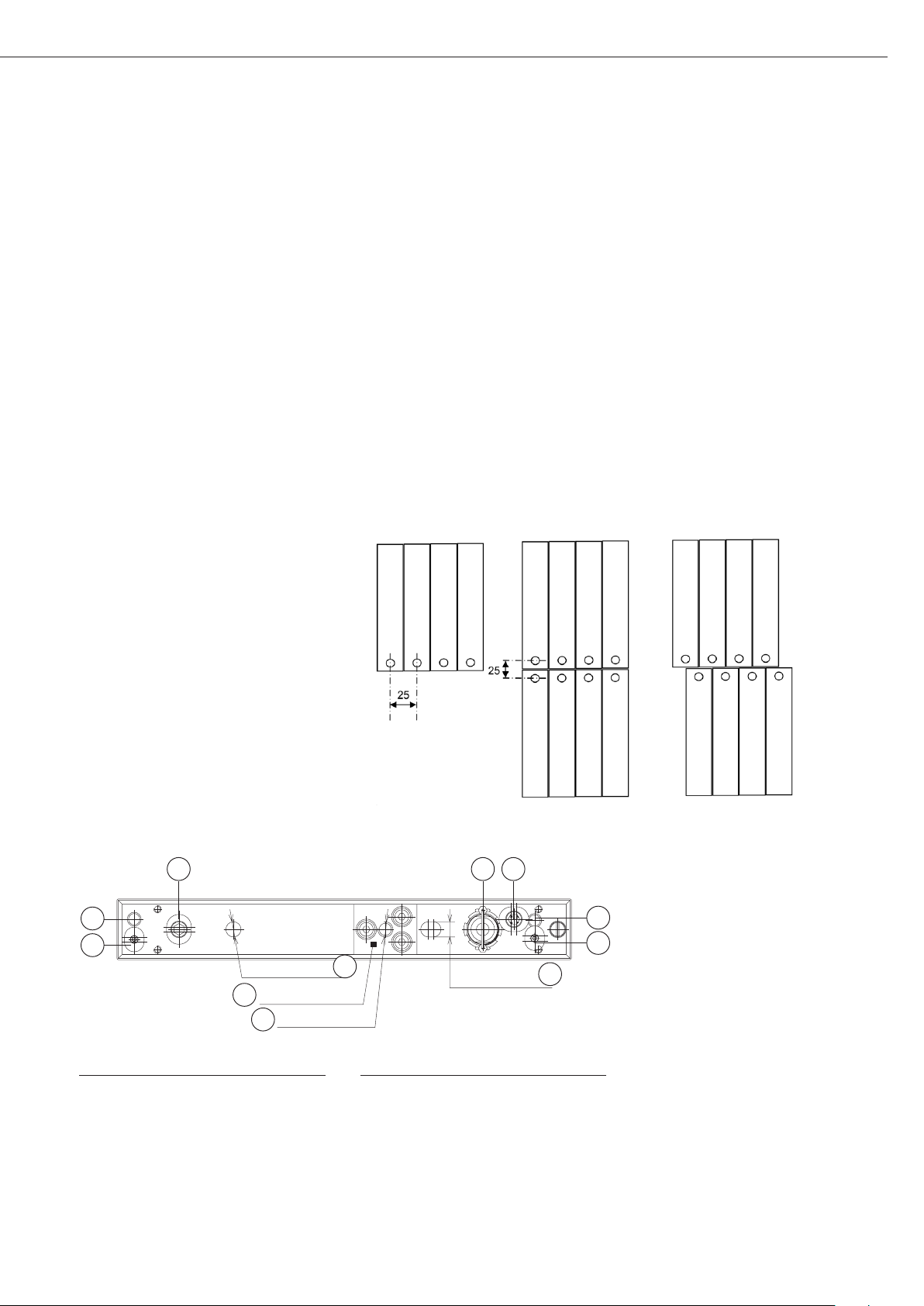
Multiple cells can be interconnected
in a row, 25 mm apart from each other.
It is also possible to interconnect them
in two rows, where a 25-mm distance
can be achieved.
Using special measures, a protection
rating of IP68 can be achieved when
the system using the weigh cell is being
cleaned. This function also has a pneumatic drive, which easily enables the
interconnection of multiple cells (see
Section „Interconnection of Multiple
Cells“).
The cells have a built-in calibration
weight, which can be used to check
that the cells are functioning properly
or to readjust the sensitivity of the cells.
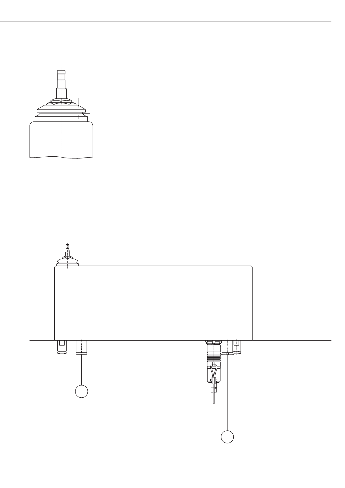
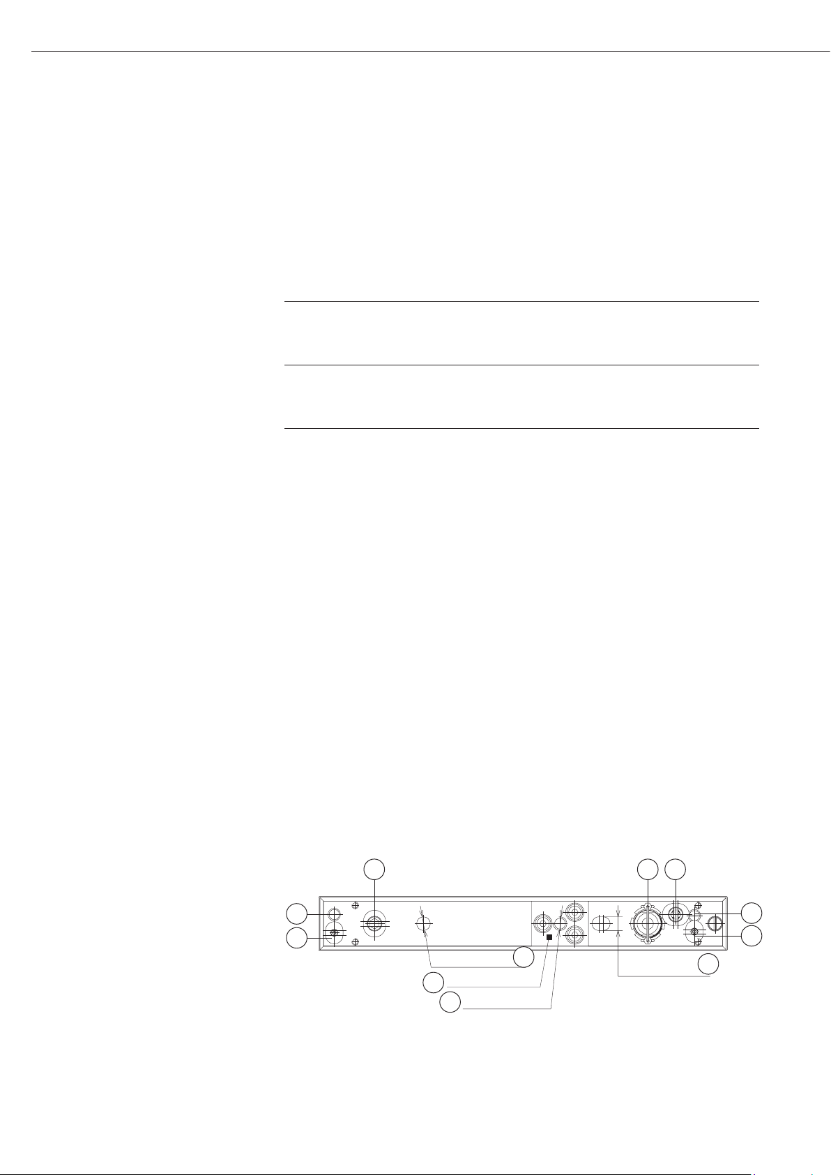
1.2 Connections
8 5 9
10
6
d 6 H8; 6 deep
Mounting surface
1
M6; 6 deep
2
6 and 7 are sintered filters.
Pos. Description
Mounting surface
Threaded hole for mounting
Positioning holes
Electrical connection
Pressure inlet weight circuit
6 bar, d 3 mm
All dimensions are given in millimeters
3
6 H8; 6 deep
Pos. Description
Pressure inlet closing mechanism
6 bar, d 3 mm
Air inlet for rinsing cycle < 50 mbar
Air outlet for rinsing cycle
< 50 mbar
Pressure outlet for and
1.3 Securing the Weigh Cell
Secure the weigh cell at low tension to
the mounting surface 1 (second Figure)
with an M6 screw. Observe the maximum screw installation depth.
10
Use the positioning holes 3 and 4 to
align the weigh cell exactly.
7
Use the M6 fixing screw to connect to
4
the device ground in order to divert
electrostatic charges.
3
Page 4
d
d
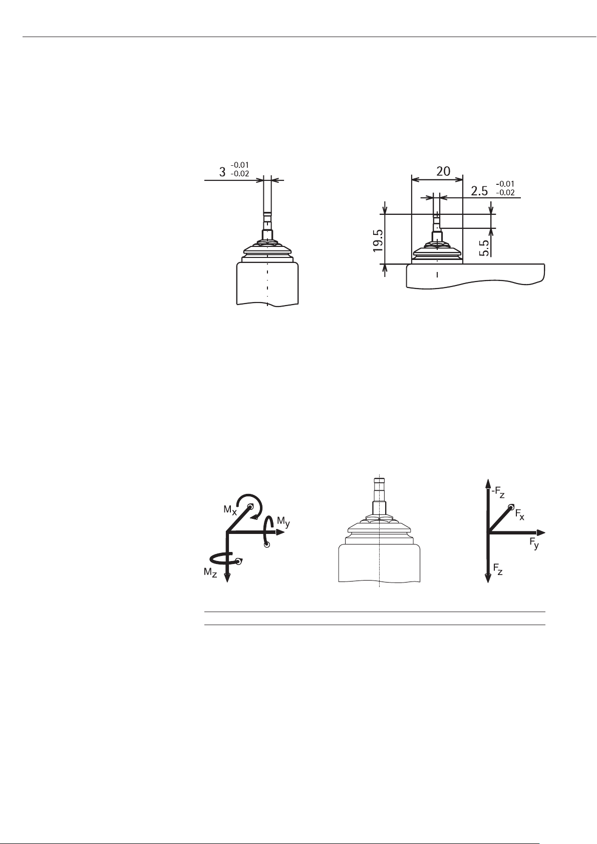
2. Transducer
The weigh cell is equipped with a partially beveled cylindrical stud (see Figure) for securing a
transducer at the customer‘s premises. The beveling (2.5 mm) serves to secure the transducer
in a specified direction of rotation.
The transducer can be installed on this stud using clamps, for example. The transducer
should consist of conductive, non-magnetic material in order to minimize electrostatic and
magnetic interference. The transducer must weigh 5 g ± 0.1 g, so that the full weighing
capacity of 20 g can be achieved. It must be smaller than 10 g in order to use the internal
calibration function. Remove the transducer when transporting the weigh cell.
The stud is overload protected. Do not exceed the maximum forces and torque. The stud
may bend due to the effects of forces or torque.
Bending can occur if torque is greater than 2 mNm for a 5 g transducer.
Model Max. torque Screwing torque Max. force opposite to Max. forces
M
WZA25-NC 0.1 Nm 0.5 Nm 2 N 2 N
, My, Mz direction of load (-Fz) Fx, Fy, F
x
z
4
Page 5
8
9
Shield plate
Gap
Seal ring
3. IP Protection
The cell has a rating of IP44 in normal weighing mode. This protection rating is only valid
when there is a gap between the shield plate and the seal ring.
The gap is sealed by applying the pressure inlet (7) at 6 bar. A closing mechanism is set
in the space, which pulls the stud and shield plate against the seal ring. Observe a distance
of approx. 1 mm between the transducer and the rest of the equipment. In this position,
the cell does not provide a weight value; instead it displays the error message, “H.”
After the closing mechanism is opened, the weigh cell requires some time to restabilize.
The connection side of the weigh cell can be sealed by placing a seal between the lower
edge of the weigh cell housing and the mounting plate. Use as soft a sealing material as
possible (e.g., Sili-Rex silicone foam round cords from Rexio GmbH Co. KG, Westerrönfeld,
Germany) in order to minimize the force on the cell housing. This process causes the plug
and pressure outlet to be outside of the contamination and cleaning area (process side).
The connection side has a rating of IP44.
Cleaning
Apply overpressure to ensure that cleaning fluid does not penetrate the weigh cell.
To do so, apply an overpressure of max. 50 mbar through overpressure inlets 8 and 9 to the
weigh cell interior (use dry filtered oil-free and particle-free air only).
Once cleaning is successfully complete, the closing mechanism can be opened, and air can
continue to be blown into the cell. The air exits through the gap and dries the area after
cleaning.
Process side
Connection side
5
Page 6
4. Internal Calibration
8 5 9
5. Cooling Air Operation
The weigh cell has a built-in calibration
weight, which can be used to check that
the cell is functioning properly or to readjust the sensitivity of the cell. The built-in
calibration weight has a mass of approx.
10 g. It is calibrated at the factory.
The calibration value is entered in the
data record as the “user-defined weight“
and should not be overwritten (except
when recalibration occurs). Use the Public
CAS software tool to enter the calibration
weight.
The weigh cell is calibrated/adjusted in
the same way as it would be using a
user-defined weight. The menu is pre-set
accordingly (1.1.9.3 and 1.1.10.1).
Calibration is triggered via interface
command Esc f1_ when the weigh cell has
nothing on it (see installation instructions).
Upon triggering the calibration, 6 bar must
be applied to the pressure inlet for the
weight circuit
exceeded. Then switch off the pressure.
until the value has been
The weigh cell must not exceed an internal temperature of 60°C during cleaning.
Monitor the internal temperature when the cell is being cleaned with hot cleaning agents.
Monitoring can be done via the following XBPI commands:
XBPI Commands: Temperature Sensor
For in-depth information concerning Sartorius xBPI-functions refer to manual “Sartorius
– Description of Protocols and Functions in the Weighing Platform Interface”
Read Temperature
Fct.No. Input Output
076H Unsigned 1 Float5 (xBPI command response)
Input parameter Unsigned 1 (1) relates to existing sensor (only sensor 1)
Bit Explanation (if bit =1)
0 Sensor 1
Example
Function XBPI-Command Response
Read Temperature Len, 01, 09, 76, 21, 00, Chk Len, 41, 35, float5, Chk
example: 06:01 09 76 21 example:
00:A7 08:41 35 41 CE 05 E0 00:72
→ internal Temperature = 25.753°C
Len = Numbers of bytes to follow, including the checksum
Chk = Checksum of the entire message including the “length” byte; Module 256 – sum of
all preceding bytes(*)
(*) for comprehensive information refer to manual “Sartorius – Description of Protocols
and Functions in the Weighing Platform Interface”
Please note:
– The temperature sensor is not individually calibrated - it is good to measure temperature
differences of some degrees.
– The temperature sensor is thermally connected to a massive metallic part - it is much
slower than the air temperature.
Dry, oil-free, filtered cooling air can be directed through the cell if the temperature
of the cleaning agent is greater than 60°C (inlet connection 8, outlet connection 9).
The pressure within the cell cannot exceed 50 mbar, and the air volume cannot exceed
1500 liters per hour. Cooling air can also be used to return the cell to an operating
temperature more quickly once the cell has been successfully cleaned. After cleaning,
allow the cooling air to flow in, keeping the closing mechanism of the shield plate open
(no pressure to connection 7). This process dries the area around the seal.
Cooling results greatly depend on how the weigh cell is installed and therefore must be
determined by testing it on site.
10
10
6
d 6 H8; 6 deep
Mounting surface
1
M6; 6 deep
2
3
6 H8; 6 deep
4
7
6
Page 7

6. User-Specific Housing
One or more weigh cells can be equipped with an additional
housing for their protection or to make cleaning easier.
This housing should be made of non-magnetic materials.
Stud
Lock nut
Shield plate
Sealing plate
To seal the weigh cell(s) in an IP-compliant way, complete the
following steps:
– Remove the weighing pan.
– Loosen the lock nut of the shield plate using the supplied tools.
Ensure that the lock nut is unscrewed evenly, to avoid transfer-
ring torque to the stud.
– Unscrew the lock nut and shield plate from the stud.
– Unscrew the sealing plate using the supplied tools.
– Unscrew the coupling nut located under the sealing plate.
– Attach the housing with a drill hole with a diameter of 11 mm
and a maximum thickness of 2.5 mm.
– Reattach the parts in a reverse order to the way they were
removed.
– Set the gap between the shield plate and sealing plate to approx.
1 mm. (Use a thickness gauge.)
Housing
7
Page 8

7. Interconnection of Multiple Cells
8. Optimal Operating Point
7.1 Interconnection of Pneumatic Functions
The pressure inlets for triggering calibration (6) or the closing
mechanism (7) can be interconnected using T-pieces and controlled
via one valve.
Overpressure can be applied to multiple cells by interconnecting
the sealing air inlets (8) and (9) of multiple cells using the
appropriate T-pieces. The maximum overpressure of 50 mbar must
not be exceeded during this process.
During cooling air operation, the air must be evenly distributed
among all connected cells, and the maximum overpressure must
not be exceeded. Use the appropriate dimensions for inlet and
outlet cross-sections and distributions.
7.2 Interconnection of Electronic Functions
The electricity supply inlets can be interconnected to an adaptor
with the appropriate power capacity. Ensure that the shields of the
data output cable are placed only on one side of the E-box and
that the signal lines are galvanically separated.
Multiple cells can be connected to a computer via several RS-232
interfaces or via a terminal server (e.g., multiple-port NPort Server
from Moxa).
When a weighing system is accelerated in the direction of the
weighing axis, acceleration forces of effective seismic masses occur,
which show in the measuring signal as interference.
By filtering the signal, the effect of this interference on the measurement result is reduced. The size of the effective seismic masses
depends on the mass distribution on the measurement system and
the size of the mass on the stud. The measurement system used in
the WZA25-NC has a shape and size that has minimal influence,
if the system weighs 15 g (transducer and object being weighed).
This operating point is also optimal in terms of sensitivity drifts and
should be strived for every time the weighing system is operated.
8
Page 9
Befestigungsfläche
6 H8; 6 tief
d 6 H8; 6 tief
M6; 6 tief
10
6
8 5 9
10
7
3
1
2
4
Inhalt
1. Allgemeine Hinweise
1. Allgemeine Hinweise . . . . . . . 9
1.1 Verwendungszweck . . . . . . . . 9
1.2. Anschlüsse . . . . . . . . . . . . . . . 9
1.3. Befestigung der Wägezelle . . . 9
2. Lastaufnahme ............ 10
3. IP- Schutz ...............11
4. interne Justierung......... 12
5. Kühlluftbetrieb ........... 12
6. Umgehäuse . . . . . . . . . . . . . . 13
7. Zusammenschalten
mehrerer Zellen........... 14
7.1 Zusammenschalten der
pneumatischen Funktionen .. 14
7.2 Zusammenschalten der
elektronischen Funktionen ...14
8. Optimaler Arbeitspunkt..... 14
Diese Applikationshinweise stellen eine
Ergänzung der beiliegenden Installationsanleitung dar. Die Applikationshinweise gehen speziell auf die Besonderheiten der WZA25-NC ein.
Bitte lesen sie sich aufmerksam die
oben genannte Installationsanleitung
durch.
1.1 Verwendungszweck
Die Wägezelle WZA25-NC wurde für
automatische Wägeanlagen und Dosiereinrichtungen insbesondere in der
Pharmaindustrie entwickelt.
Mehrere Zellen können in einer Linie
mit 25 mm Abstand zusammengeschaltet werden. Es sind natürlich auch
2 Reihen die wiederum einen Abstand
von 25 mm haben können möglich.
Durch besondere Maßnahmen kann
während des Reinigungsprozesses
der Anlage in der die Zelle eingesetzt
wurde, ein Schutzgrad IP68 hergestellt
werden. Diese Funktion verfügt auch
über einen Druckluftantrieb, der auf
einfache Weise die Zusammenschaltung
mehrerer Zellen erlaubt (siehe Kapitel
»Zusammen schalten mehrer Wägezellen«).
Die Zellen verfügen über ein einge-
bautes Justiergewicht mit dem die
ordnungsgemäße Funktion überprüft
werden kann bzw. die Empfindlichkeit
der Zelle nachjustiert werden kann.
1.2 Anschlüsse
6 und 7 sind Sinterfilter
Pos. Bezeichnung
Befestigungsfläche
Befestigungsgewinde
Positionierlöcher
Elektrische Verbindung
Druckeingang-Gewichtsschaltung
6 bar, d 3 mm
Alle Angaben in Millimetern
Pos. Bezeichnung
Druckeingang-Verschlussmecha-
Lufteintritt Spüllauf < 50 mbar,
Luftaustritt Spüllauf < 50 mbar,
Druckausgang für und
nismus 6 bar, d 3 mm
d 6 mm
d 6 mm
1.3 Befestigung der Wägezelle
Die Wägezelle spannungsarm auf
der Auflagefläche 1 (Bild 2) mit einer
Schraube M6 befestigen. Die maximale
Einschraubtiefe beachten. Für eine
exakte Ausrichtung dienen die Positionierlöcher 3 und 4.
Die Verbindung zur Gerätemasse für die
Ableitung elektrostatischer Ladungen
erfolgt über die Befestigungsschraube
M6.
9
Page 10

d
d
2. Lastaufnahme
Für die Befestigung eines kundenseitigen Lastaufnehmers ist an der Wägezelle ein teilweise
abgeflachter zylindrischer Zapfen vorgesehen (siehe Bild). Die Abflachung (2,5 mm) dient
einer in Drehrichtung definierten Befestigung des Lastaufnehmers.
Auf diesen Zapfen kann der Lastaufnehmer z.B. durch Klemmung angebracht werden.
Der Lastaufnehmer sollte aus leitfähigem, unmagnetischem Material bestehen um elektrostatische und magnetische Einflüsse zu minimieren. Das Gewicht des Lastaufnehmers muss
5 g ± 0,1 g betragen, damit der volle Wägebereich von 20 g zur Verfügung steht. Er muss
kleiner als 10 g sein, um die interne Justierung nutzen zu können. Bei einem Transport der
Zelle den Lastaufnehmer entfernen.
Der Zapfen ist überlastgesichert. Die maximalen Kräfte und Momente nicht überschreiten.
Der Zapfen kann sich beim Einwirken von Kräften oder Momenten neigen.
Mit einer Neigung ist ab einem Moment von 2 mNm bei einem 5 g Lastaufnehmer zu
rechnen.
Modell Max. Momente Schraubmomente Max. Kraft entgegen Max. Kräfte
M
WZA25-NC 0,1 Nm 0,5 Nm 2 N 2 N
, My, Mz der Lastrichtung (-Fz) Fx, Fy, F
x
z
10
Page 11

8
9
Schirmplatte
Spalt
Dichtungsring
3. IP- Schutz
Die Zelle hat im normalen Wägebetrieb IP44. Dieser Schutzgrad ist bedingt durch einen
Spalt zwischen der Schirmplatte und dem Dichtungsring.
Der Spalt wird abgedichtet durch Beaufschlagung des Druckeinganges (7) mit 6 bar. Dadurch
wird ein Verschlussmechanismus in Gang gesetzt, der den Zapfen mit der Schirmplatte
gegen den Dichtungsring zieht. Den Hub von ca. 1 mm beachten bei der Konstruktion des
Lastaufnehmers und seiner Umgebung. Die Zelle liefert in dieser Stellung keine Wägewerte,
sondern die Fehlermeldung „H“.
Nach Öffnen des Verschlussmechanismus benötigt die Wägezelle einige Zeit um sich wieder
zu stabilisieren.
Die Abdichtung der Anschlussseite der Wägezelle kann durch eine Dichtung zwischen der
Unterkante des Wägezellengehäuses und der Montageplatte erfolgen. Ein möglichst weiches
Dichtungsmaterial (z.B. Sili-Rex Silikonschaum-Rundschnüre der Firma Rexio GmbH Co. KG,
Westerrönfeld) verwenden, um die Kraft auf das Zellengehäuse klein zu halten. Durch diese
Maßnahme liegen der Stecker und die Druckausgänge außerhalb des Verschmutzungs- und
Reinigungsbereiches (Prozessseite). Die Anschlussseite hat IP44.
Reinigung
Einen Überdruck realisieren zur Sicherheit gegen eindringende Reinigungsflüssigkeit.
Dazu den Innenraum der Wägezelle über die Überdruckeingänge 8 und 9 mit einem Überdruck von maximal 50 mbar versorgen (nur trockene gefilterte öl- und partikelfreie Luft
verwenden).
Nach erfolgter Reinigung kann der Verschlussmechanismus geöffnet werden und weiterhin
Luft in die Zelle geblasen werden. Die Luft tritt am Spalt aus und trocknet anhängige
Tropfen.
Prozessseite
Anschlussseite
11
Page 12

4. Interne Justierung
Befestigungsfläche
6 H8; 6 tief
d 6 H8; 6 tief
M6; 6 tief
10
6
8 5 9
10
7
3
1
2
4
5. Kühlluftbetrieb
Die Wägezelle verfügt über ein eingebautes
Justiergewicht mit dem die ordnungsgemäße Funktion überprüft werden kann
bzw. die Empfindlichkeit der Zelle nachjustiert werden kann. Das eingebaute Kalibriergewicht hat eine Masse von ca. 10 g.
Es ist werksseitig kalibriert. Der Kalibrierwert ist als „Anwendergewicht“ im
Datensatz eingetragen und sollte nicht
überschrieben werden (außer bei einer
Neu kalibrierung). Zum Eintragen das
Software-Tool Public CAS verwenden.
Eine Justierung/ Kalibrierung erfolgt
wie eine Justierung/ Kalibrierung mit
Anwendergewicht. Das Menü ist entsprechend voreingestellt (1.1.9.3. und
1.1.10.1.).
Das Justieren wird bei entlasteter Wägezelle
über einen Schnittstellenbefehl Esc f1_ ausgelöst (siehe auch Installationsanleitung).
Nach Anforderung des Justiergewichtes
muss der Druckeingang für die Gewichtsschaltung
werden bis der Wert übernommen wurde.
Danach den Druck abschalten.
mit 6 bar beaufschlagt
Ü
Die Wägezelle darf bei der Reinigung maximal eine Innentemperatur von 60°C haben.
Die Innentemperatur überwachen, wenn die Zelle mit wärmeren Reinigungsmedien
behandelt wird.
Das kann über folgende XBPI Befehle geschehen:
XBPI-Befehle: Temperatursensor
Ausführliche Informationen zu Sartorius xBPI-Funktionen siehe Sartorius-Anleitung
„XBPI-Protokoll- und Funktionsbeschreibung der Wägeplattformen“.
Temperatur lesen
Fkt.-Nr. Eingang Ausgang
076H Unsigned 1 Float5 (xBPI-Befehlsantwort)
Der Eingangsparameter Unsigned 1 (1) bezieht sich auf den vorhandenen Sensor
(nur Sensor 1)
Bit Erklärung (wenn Bit =1)
0 Sensor 1
Beispiel:
Funktion XBPI-Befehl Antwort
Temperatur lesen Len, 01, 09, 76, 21, 00, Chk Len, 41, 35, float5, Chk
Beispiel: 06:01 09 76 21 Beispiel:
00:A7 08:41 35 41 CE 05 E0 00:72
→ Innentemperatur = 25,753°C
Len = Anzahl der folgenden Bytes einschließlich Checksumme
Chk = Checksumme des gesamten Telegramm einschließlich des Längenbytes;
Modul 256 – Summe aller vorhergehenden Bytes (*)
(*) ausführliche Informationen siehe Sartorius-Anleitung „XBPI-Protokoll- und Funktionsbeschreibung der Wägeplattformen“
Bitte beachten!
– Der Temperatursensor ist nicht einzeln kalibriert. Daher sollten Temperaturdifferenzen
von einigen Grad festgestellt werden.
– Der Temperatursensor ist thermisch mit einem massiven Metallteil verbunden.
Er ist erheblich langsamer als die Lufttemperatur.
Bei einer Reinigungsmitteltemperatur über 60°C kann trockene, ölfreie gefilterte Kühlluft
durch die Zelle geleitet werden (Eingang Anschluss 8, Ausgang Anschluss 9). Der Druck
innerhalb der Zelle darf 50 mbar und die Luftmenge 1500l/Stunde nicht übersteigen.
Die Kühlluft kann auch verwendet werden um nach erfolgter Reinigung die Zelle
schneller wieder auf Betriebstemperatur zu bringen. Nach einer Reinigung die Kühlluft
einströmen lassen und dabei den Verschlussmechanismus der Schirmplatte geöffnet
halten (kein Druck auf Anschluss 7). Dadurch wird der Bereich um die Dichtung
getrocknet. Das Ergebnis der Kühlung hängt stark von der Einbausituation ab und ist
daher durch eigene Untersuchungen zu ermitteln.
12
Page 13

6. Anwenderspezifisches Gehäuse
Eine oder auch mehrere Wägezellen können zu ihrem Schutz
bzw. zur weiteren Verbesserung der Reinigungssituation mit
einem zusätzlichen Gehäuse versehen werden.
Dieses Gehäuse sollte aus unmagnetischem Material bestehen.
Zapfen
Kontermutter
Schirmplatte
Dichtplatte
Zur IP-gerechten Abdichtung wird wie folgt vorgegangen:
– Waagschale entfernen
– Kontermutter von Schirmplatte mit Hilfe der mitgelieferten
Werkzeuge lösen.
Dabei ist auf gleichzeitiges gegensinniges Verdrehen zu achten,
um keine Momente auf den Zapfen zu übertragen.
– Kontermutter und Schirmplatte vom Zapfen abschrauben.
– Dichtplatte mit Hilfe des mitgelieferten Werkzeuges abschrau-
ben.
– Die unter der Dichtplatte befindliche Überwurfmutter abschrau-
ben.
– Gehäuse mit Bohrung Durchmesser 11 mm und maximaler Dicke
2,5 mm aufsetzen.
– In umgekehrter Reihenfolge Teile wieder montieren.
– Den Spalt zwischen Schirmplatte und Dichtplatte auf ca. 1 mm
einstellen.
(Fühllehre verwenden)
Gehäuse
13
Page 14

7. Zusammenschalten mehrer Wägezellen
8. Optimaler Arbeitspunkt
7.1 Zusammenschalten der pneumatischen Funktionen
Die Druckeingänge für die Auslösung der Justierfunktion (6) bzw.
des Verschlussmechanismus (7) können über T- Stücke zusammengeschaltet und über ein gemeinsames Ventil angesteuert werden.
Die Herstellung eines Überdrucks in mehreren Zelle kann über das
Zusammenschalten der Spühllufteingänge (8) und (9) mehrer Zellen
über entsprechende T- Stücke erfolgen. Der maximale Überdruck
von 50 mbar darf dabei nicht überschritten werden.
Bei Kühlluftbetrieb ist auf eine gleichmäßige Verteilung der Luft auf
alle angeschlossenen Zellen, sowie auf den maximalen Überdruck
in den Zellen zu achten. Die Querschnitte der Zu- und Ableitungen
und die Verteilungen bitte hierzu entsprechend dimensionieren.
7.2 Zusammenschalten der elektronischen Funktionen
Die Stromversorgungseingänge können an einem entsprechend
leistungsfähigem Netzteil zusammengeschaltet werden. Bitte
beachten Sie, dass die Schirme der Datenausgangskabel nur einseitig auf der E-Boxseite aufgelegt sind und die Signalleitungen
galvanisch getrennt sind.
Datenseitig können mehrere Zellen an einen Rechner mit
mehreren RS232 Schnittstellen oder über einen Terminalserver
(z.B. 4, 8, …-fach NPortserver der Fa. Moxa) angeschlossen werden.
Bei Beschleunigungen eines Wägesystems in Richtung der Wägeachse treten Beschleunigungskräfte der wirksamen seismischen
Massen auf, die in das Messsignal als Störungen eingehen.
Durch die Signalfilterung wird der Einfluss dieser Störungen auf
das Messergebnis reduziert. Die Größe der wirksamen seismischen
Masse hängt von der Masseverteilung am Messsystem ab und
ist abhängig von der Größe der Masse am Zapfen. Das in der
WZA25-NC verwendete Messsystem ist so dimensioniert, dass der
Einfluss bei einer Masse von 15 g (Lastaufnahme und Wägegut) ein
Minimum hat. Dieser Arbeitspunkt ist auch bezüglich der Empfindlichkeitsdriften optimal und sollte angestrebt werden.
14
Page 15

Page 16

Sartorius Weighing Technology GmbH
Weender Landstrasse 94–108
37075 Goettingen, Germany
Phone +49.551.308.0
Fax +49.551.308.3289
www.sartorius.com
Copyright by Sartorius,
Goettingen, Germany.
All rights reserved. No part
of this publication may
be reprinted or translated in
any form or by any means
without the prior written
permission of Sartorius.
The status of the information,
specifications and illustrations
in this manual is indicated
by the date given below.
Sartorius reserves the
right to make changes to the
technology, features, specifications
and design of the equipment
without notice.
Status:
June 2013,
Sartorius Weighing Technology GmbH
Goettingen, Germany
Printed in Germany on paper that has been
bleached without any use of chlorine
W_WZA25-NC_Applikationshinw · KT
Publication No.: WWZ6010-a13064
 Loading...