

Sartorius WZA224-LC, WZA8202-L, WZA -L Series, WZA224-L, WZA523-L Installation Instructions Manual
Page 1
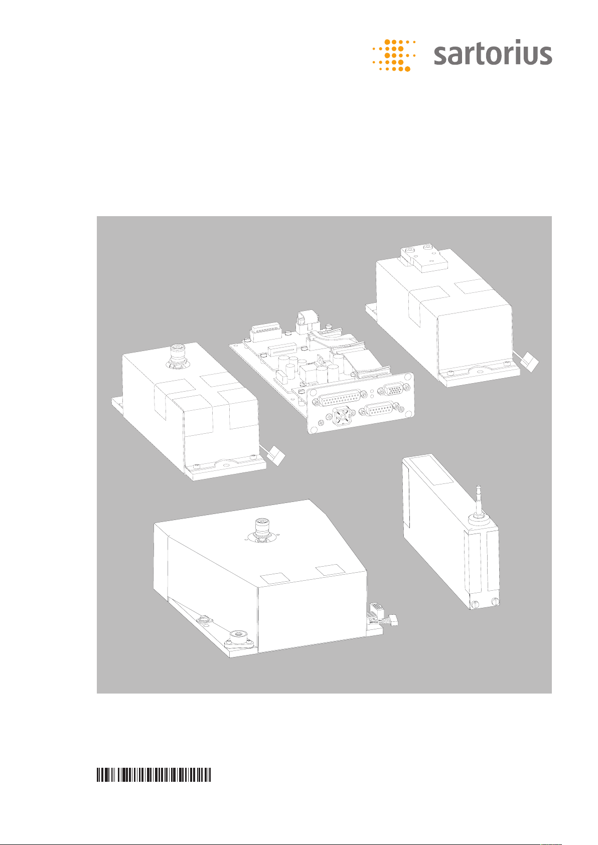
Installation Instructions
Sartorius Weigh Cells
Models WZA...-L, WZA224-LC
98648-019-04
Page 2

Contents Warnings and Safety Instructions
Contents 2
Warning and Safety Instructions 2
General View of the Equipment 3
Installation 5
Storage and Shipping Conditions 5
Incoming Inspection 5
Equipment Supplied 5
Installation Instructions 5
Connecting the Weigh Cell
to the Electronics Unit 5
Connecting the Device to AC Power 6
Securing the Weigh Cell 7
Leveling the Load Receptor 7
Securing the Transducer 7
Operation 9
Notes on Analytical Weighing 9
Below-Cell Weighing 10
Configuration 13
Parameter Settings (Overview) 16
Data Interface Port: RS-232 24
Pin Assignment Chart 26
Cabling Diagram 27
Error Codes 28
Overview 30
Specifications 30
Dimensions (Scale Drawings) 31
Accessories (Options) 36
EC/EU Declaration of Conformity 37
Form: Returns 38
Decontamination Declaration 39
Intended Use
Weigh cells have been developed for
– Use in measuring devices and
production machinery
– High-precision weighing within limited
space
– Precise weight determination on active
production lines
! The weigh cells are not devices; they are
modules to be added on. Only create an
EC Declaration of Conformity once the
device has been finalized. Direct sale to
end customers is not permitted due to
the lack of a CE marking.
Safety
§ The user of the weigh cell should take
into account at least the following
points with regards to the complete
product with the installed weigh cell:
– Compliance with directives and
standards for electrical equipment
– Electromagnetic compatibility of the
complete device
– Compliance with mandatory safety
regulations.
§ Read these installation instructions
thoroughly before using your weigh
cell. That way you will prevent damage
to the equipment.
§ These installation instructions only
describe the technological specifications
of the weigh cell and the conditions
that must be observed during
installation.
! Always make sure that the equipment
is disconnected from power before
performing any work on it.
Installation
! Do not use this equipment in hazardous
areas, zones exposed to explosive
gases or dusts, nor areas exposed to
potentially explosive materials.
! Use of the weigh cell in areas where
medical equipment is operated is not
permitted.
! Do not mix up weigh cell and
electronics unit:
Only connect devices that are made to
be operated together. Make sure that
the serial numbers match.
! Any improper handling, modifications
or installation work will result in
forfeiture of all claims under the
warranty.
! The requirements pertaining to
applicable installation regulations
must be followed when using
electrical equipment in systems
and environmental conditions with
increased safety requirements.
– Warning: RS-232 cables purchased from
other manufacturers: RS-232 cables
purchased from other manufacturers
often have incorrect pin assignments
for use with Sartorius equipment.
Be sure to check the pin assignments
against the chart in this manual before
connecting the cable, and disconnect
any lines identified differently from
those specified by Sartorius.
– Note on Installation:
The operator shall be responsible for
any modifications to the equipment
and for any connections of cables or
equipment not supplied by Sartorius
and must check and, if necessary,
correct these modifications and
connections.
$ If there is visible damage to the
components: Disconnect from the
supply voltage and replace the weigh
cell and electronics unit:
$ Do not unnecessarily expose the device
to aggressive chemical vapors or to
extreme temperatures, moisture, shocks,
or vibration.
$ If you have any problems with your
device:
contact your local Sartorius office,
dealer or service center.
Hotline
§ Please direct technical questions on
design, specifications and installation
to your operating partner or directly
to Sartorius:
www.sartorius.com
System Description
The products are comprised of two
components:
– A compact weigh cell that must be
secured at three points
– Electronics unit
– These compact weigh cells can be used
to determine weights within restricted
space.
2
! Installation of electronics unit:
The electronics must be installed
as set out in the guideline for
EMC compatibility.
Page 3
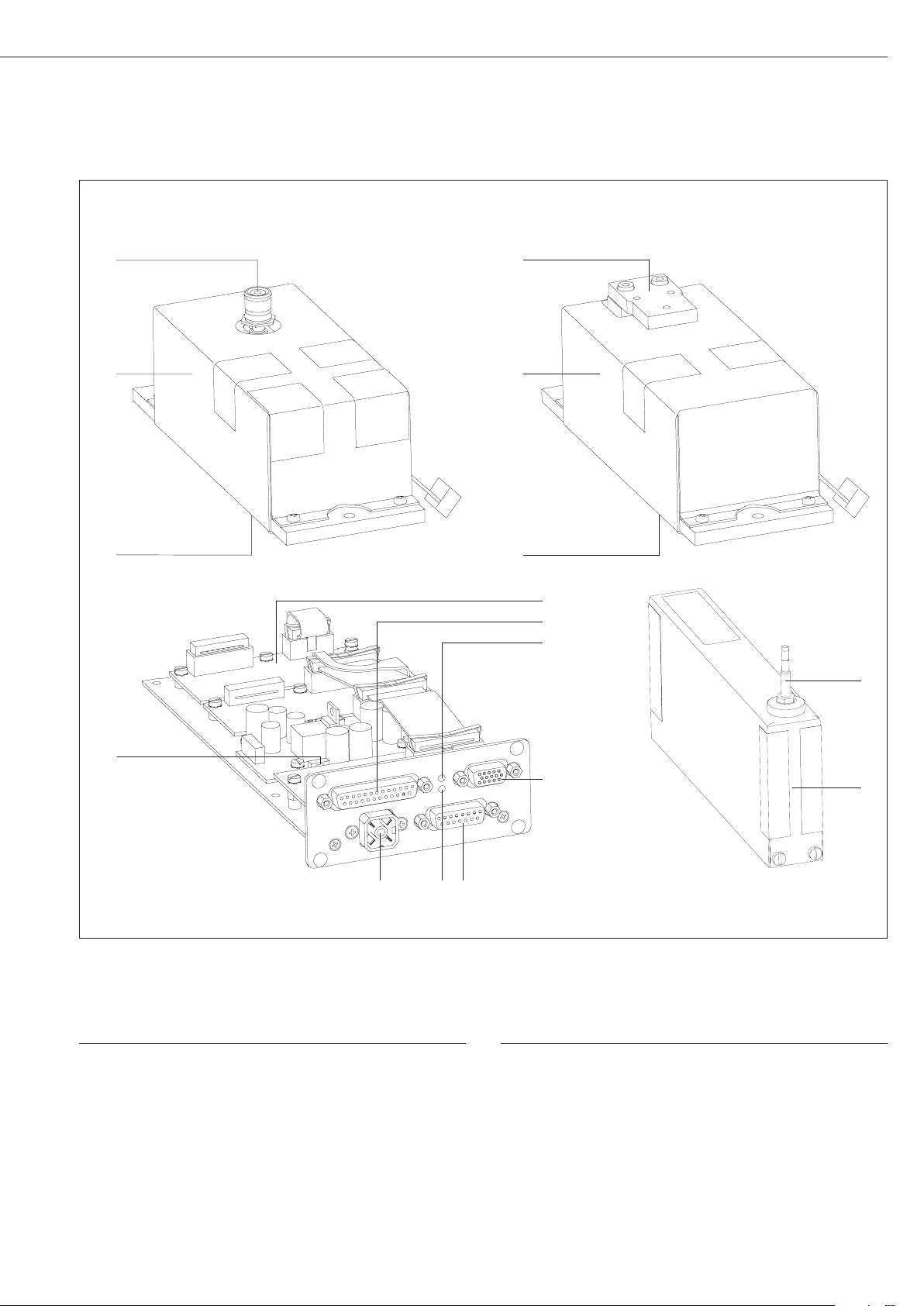
Overview of Equipment
Models WZA224-L, WZA523-L: Model WZA8202-L:
11
1
2
1
2
11
3
4
5
1
10
Pos. Description
1 Load receptor
2 Weigh cell
3 Electronics unit
4 Interface port
5 LED: RxD/DC jack (yellow)
9 8 7
6
Pos. Description
6 Female connector for optional display unit
7 Female connector for weigh cell
8 LED: TxD (red)
9 DC jack
10 Menu access switch
11 Hook for below-cell weighing
! Users should never alter any of the other screws!
2
3
Page 4
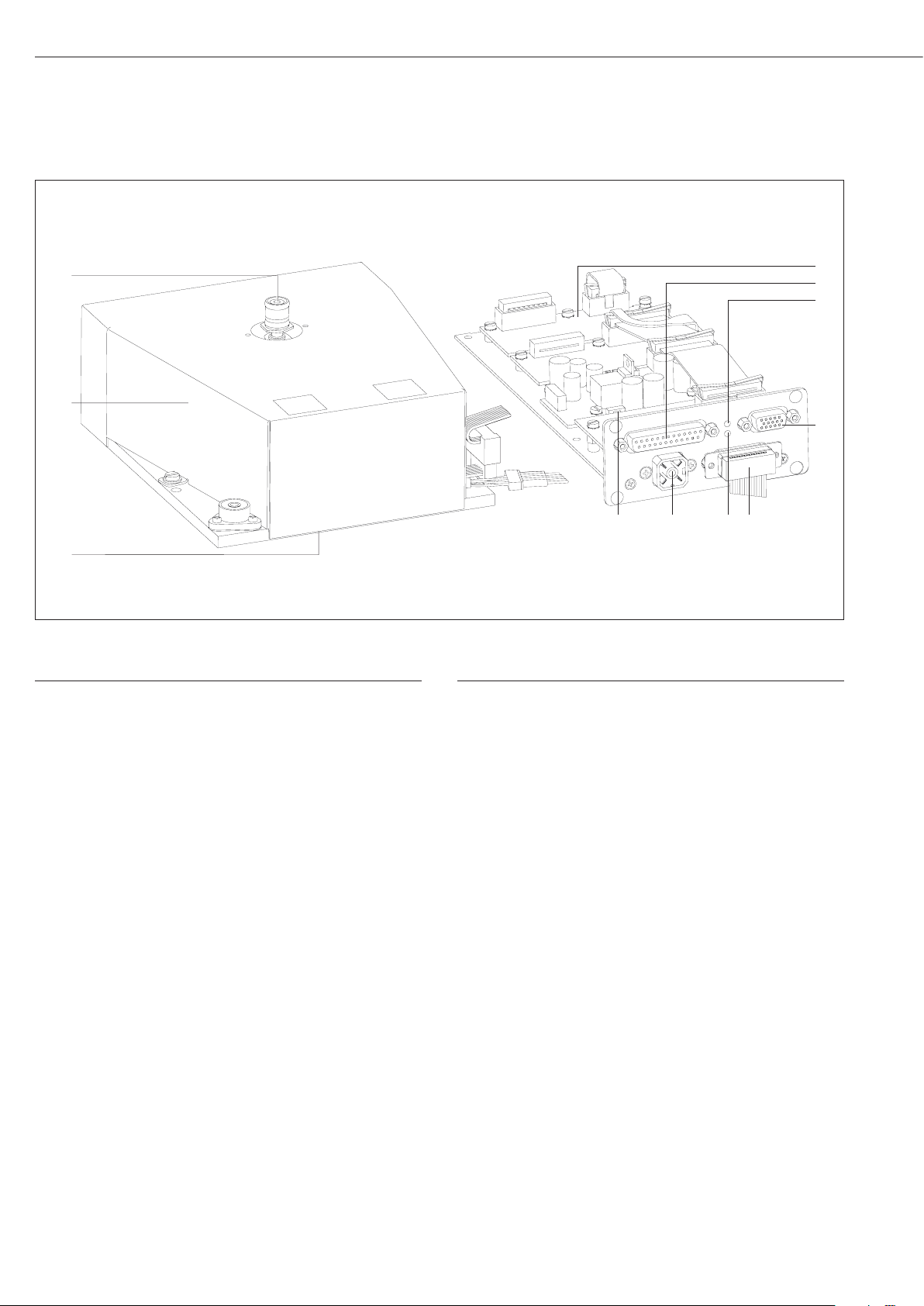
Overview of Equipment
Model WZA224-LC
1
2
11
Pos. Description
1 Load receptor
2 Weigh cell
3 Electronics unit
4 Interface port
5 LED: RxD/DC jack (yellow)
10
Pos. Description
6 Female connector for optional display unit
7 Female connector for weigh cell
8 LED: TxD (red)
9 DC jack
10 Menu access switch
11 Hook for below-cell weighing
9 8 7
3
4
5
6
! Users should never alter any of the other screws!
4
4
Page 5
Installation
Storage and Shipping Conditions
– Once the equipment has been
removed from the packaging, it may
lose accuracy if subjected to strong
vibration.
– Do not expose the equipment to
unnecessarily extreme temperatures,
moisture, shocks, blows or vibration.
$ It is a good idea to save the box and
all parts of the packaging. Only the
original packaging provides the best
protection for shipment.
$ Before packing your equipment for
shipping, unplug all connected cables
to prevent unnecessary damage.
$ Do not expose the equipment to
gravitational acceleration in excess of
2
300 m/s
is installed on the load receptor).
Incoming Inspection
The customer shall inspect the
product and packaging immediately
upon delivery for proper functioning,
completeness and absence of defects.
This is to be performed in an incoming
inspection within 10 days of delivery of
the product or service. The incoming
inspection must take place before the
equipment is installed. Any obvious
defects, errors, or incorrect delivery
must be reported in writing. Defects
detected at a later date must be
reported in writing immediately upon
detection.
Be sure to perform the following as
part of the incoming inspection:
– We recommend performing a
repeatability test using an auxiliary
draft shield to make sure there was no
damage during transport. Sartorius PC
configuration software can be used as
a tool for this.
(unless additional equipment
Installation Instructions
The weigh cell is delivered in antistatic
packaging along with its associated
analog electronics.
The other electronic components are
packaged separately on a base plate in
an antistatic bag.
Before operating, always make sure that
the serial numbers of the weigh cell and
the electronics match.
The corresponding cable must be
securely inserted into the electronics
before initial startup.
The device is designed to delivery reliable
weighing results when installed properly.
If you have any questions or difficulties
setting up your weighing system, please
contact the specialists at Sartorius.
When designing and setting up the
weigh cell and the electronics unit,
please observe the following so that
you will be able to work with added
speed and accuracy:
– Avoid exposing the equipment to the
effects of extremely high temperatures;
for example, caused by other electronic
components, heaters or direct sunlight.
– Protect the equipment from direct drafts
that come from open windows or doors.
– Avoid exposing the equipment to
excessive vibrations during weighing; for
example, caused by motors or valves.
WZA…L:
– Protect the equipment from aggressive
chemical vapors.
– Avoid extreme moisture.
– Switch the system to Standby mode
when not in use.
– Avoid the effects of magnetism.
! Always calibrate/adjust the weigh cells
after transport.
– Equipment installed on the load
receptor can interfere with weigh cell
functions.
The user accepts all liability
for production release and the
specifications of the entire equipment.
The specifications attained by your
system may differ from those listed in
the “Specifications” chapter.
Conditioning the equipment:
Moisture in the air can condense on the
surface of a cold weighing instrument
or other device whenever it is moved
to a substantially warmer place. If you
transfer the equipment to a warmer
area, make sure to condition it for
about two hours at room temperature,
leaving it unplugged from AC power.
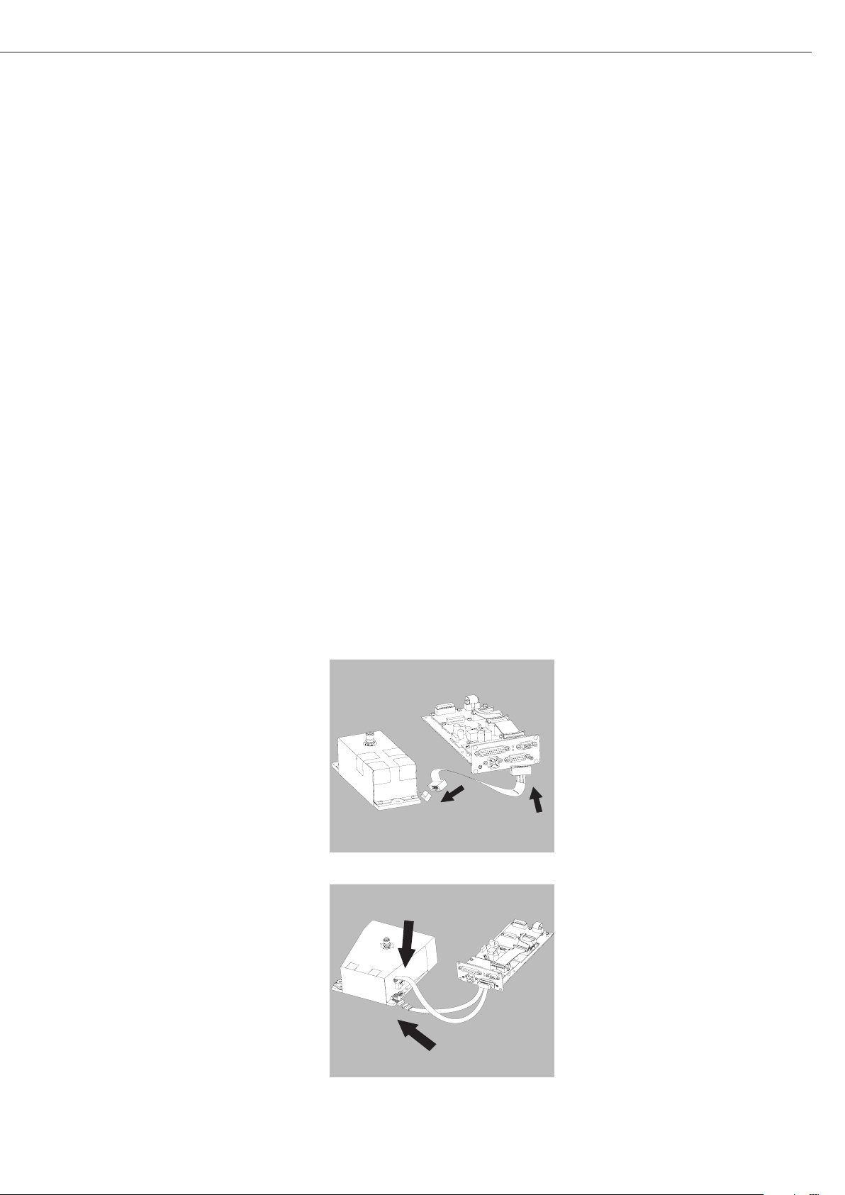
Connecting the Weigh Cell to the
Electronics Module
– Plug the male connector of the
connecting cable into the socket of the
electronics unit and the weigh cell
Equipment Supplied
– Weigh cell
– Electronics unit
– Installation instructions (this manual)
– AC adapter
– Special accessories as listed on the bill
of delivery or in accordance with any
customer-specific agreement
$ An extension cord (weigh cell –
electronics) is not included in the
equipment supplied. If required, order
separately or follow the notes on
creating an extension cord connection.
WZA224-LC:
5
Page 6
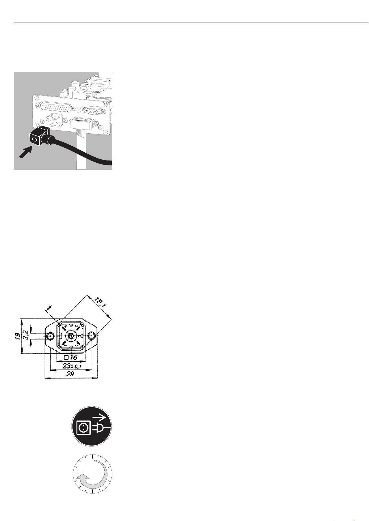
Connecting the Device to AC Power
0
45
§ Check the voltage rating and the plug design.
If they do not match your local rating or standard: Contact your supplier
Use only
– Original Sartorius AC adapters and power supplies
– AC adapters approved by specialist technicians
§ Insert the right-angle plug from the AC adapter into the jack on the electronics
module and tighten the fastening screw
§ Connect the equipment to power:
Plug the AC adapter into the wall outlet (mains)
> After connecting the power supply: The “RxD/Power” LED lights up yellow
$ Power is supplied through the DC jack (Hirschmann plug).
If the stated supply voltage or the plug design of the power cord does not comply
with your country‘s standard, please inform the nearest Sartorius representative or
your dealer.
$ Using an AC adapter other than that supplied with the equipment:
The device can be operated with a supply voltage of 12V to max. 26V.
! The power connection must be made in accordance with the regulations applicable
in your country.
Safety requirements for operation of the evaluation electronics connected to a
safety extra-low voltage (SELV) source
Safety requirements:
The external power supply must meet the requirements of EN 61010-1, Section
6: Protection Against Shock Current. Please also refer to the specifications for
classification of electrically operated equipment in EN 61010-1.
Safety precautions:
The power supply must be rated to safety extra low voltage (SELV) or grounded
(earthed) safety extra low voltage (SELV-E).
An adaptor rated to Class 2 can be plugged into any wall outlet with no additional
safety precautions required. A ground or earth terminal is connected to the housing.
The electronics module must be grounded for operation. The data interface is also
electrically connected (grounded) to the weigh cell housing.
Sizes in mm
EMC requirements:
The connector is designed for DC connections between equipment/systems that are
not connected to a DC power supply.
The cable length must not exceed 3 m.
To use an external power supply, the power source must meet the requirements of
EN 61326. The following standards apply:
Fast transients IEC61000-4-4
Surge voltages IEC 61000-4-5
Conductive HF signals IEC61000-4-6
Socket, electronics unit Type: G 4 A 5 M
Suitable matching piece Type: G 4 W 1 F,
Hirschmann order no. 932157-100
Hirschmann Electronics GmbH & Co.
Stuttgarter Strasse 45–51
72654 Neckartenzlingen
Germany
Connecting Electronic Peripheral Devices
§ Make absolutely sure to unplug the weigh cell from AC power before you connect or
disconnect a peripheral device (e.g., PC) to or from the interface port.
Warm-up Time
The amount of warm-up time required depends in part on the system used.
The guideline for these weigh cells is approx. 45 minutes. However, this guideline
must be verified by the user for the respective system/application.
6
Page 7
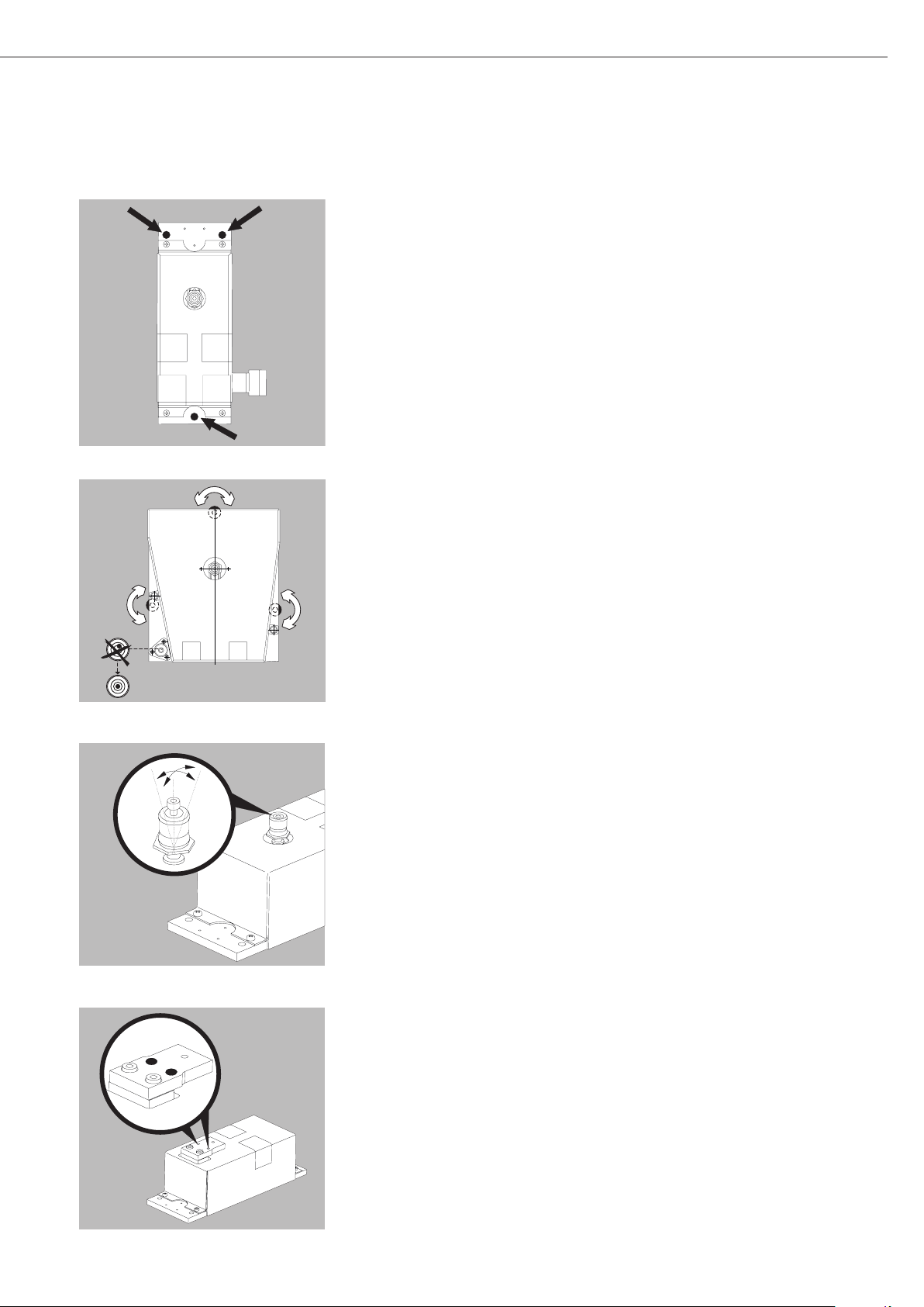
WZA...-L:
Securing the Weigh Cell
– Install the weigh cell level for optimal operation.
§ The weigh cell should be secured to the system fastening frame via the 3 drill holes.
WZA224-LC:
WZA224-LC, WZA224-L, WZA523-L:
WZA224-LC:
Leveling the Weigh Cell in a Portable Weighing System
Purpose:
– To compensate for uneven areas at the place of installation.
– To ensure that the weigh cell is placed in a perfectly horizontal position for
consistently reproducible weighing results.
– Always level the weigh cell again any time after it has been moved to a different
location.
§ Adjust the leveling feet until the air bubble is centered within the circle on the level
indicator.
WZA224-LC, WZA224-L, WZA523-L:
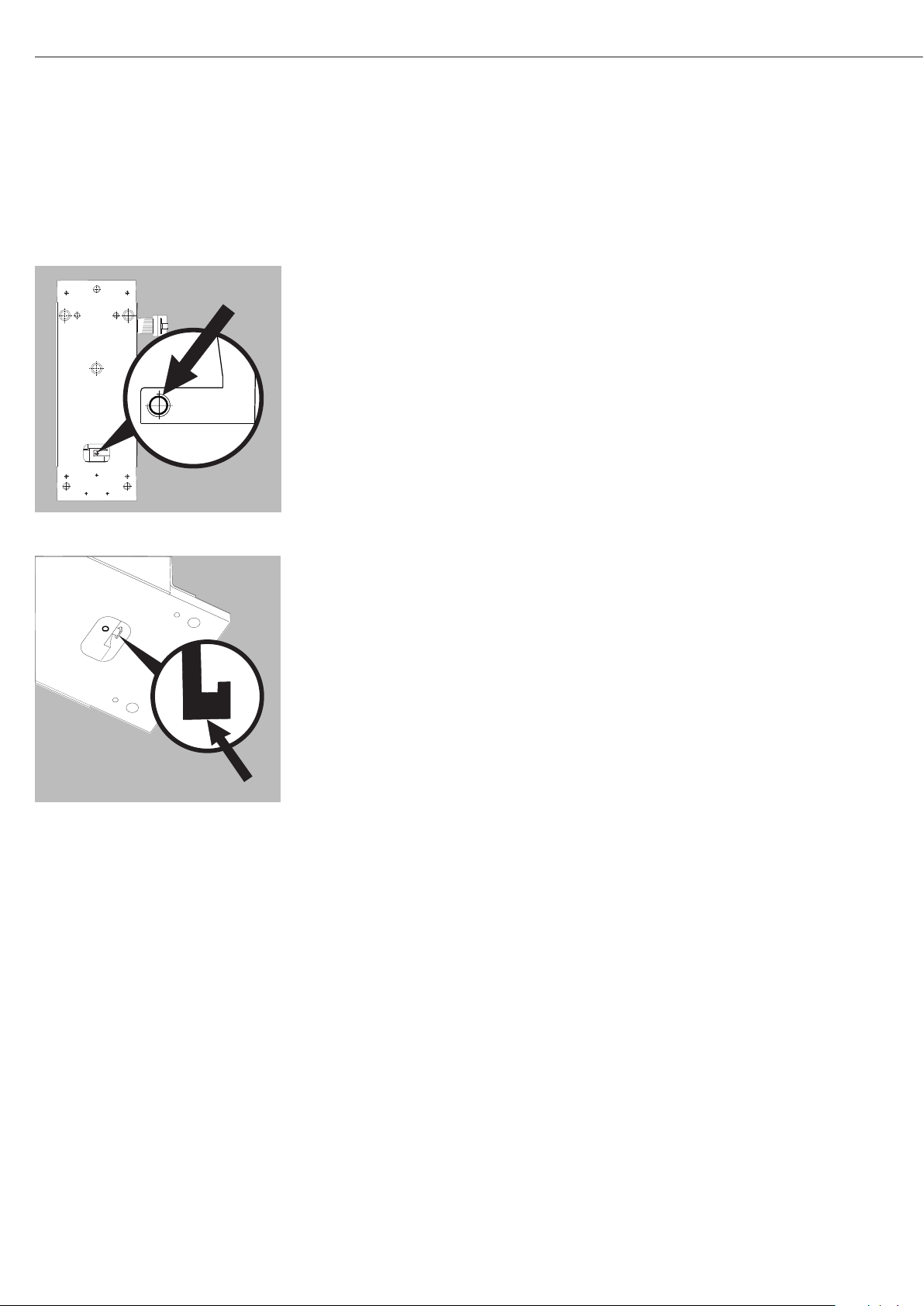
Leveling the Load Receptor for the User-specific Transducer
§ Remove the screw
§ Position radially and level the load receptor
§ Resecure the load receptor using the screw: torque 1 Nm
$ Maximum permissible load on load receptor: see table on the next page
$ Overload protection: available
! Underweight protection: none
$ The load receptor can be removed completely when used with a user-specific
transducer.
WZA8202-L:
! Make sure that the user-specific transducer is rigid.
WZA8202-L: Securing a User-specific Transducer
§ Screw the user-specific transducer to both threaded fasteners of the load receptor.
For torque values, see table on next page
“Maximum permissible load on load receptor.”
! Make sure the user-specific transducer is rigid, and is firmly attached to the load
receptor.
! Over load and underweight protection: not available
7
Page 8
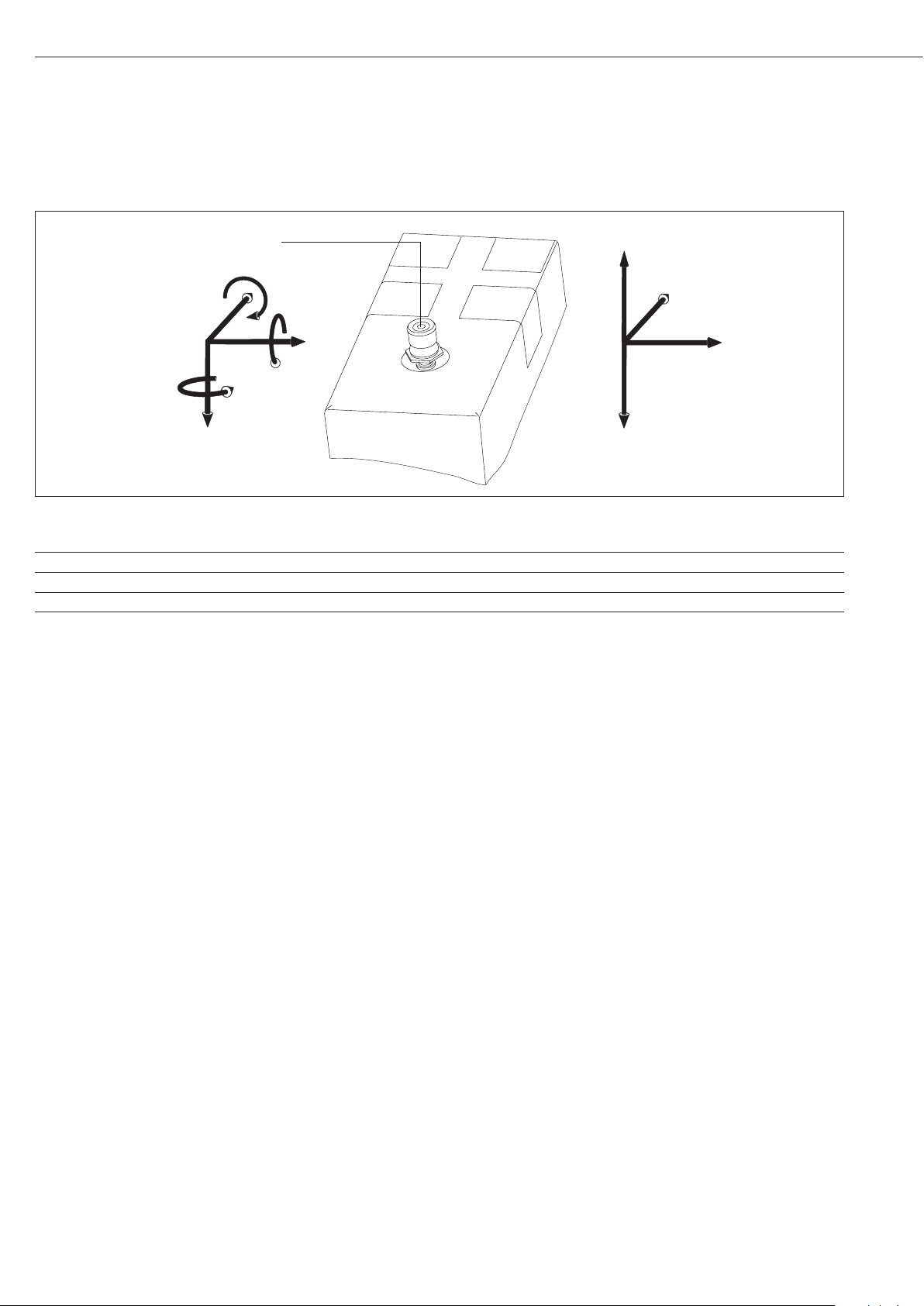
Maximum Permissible Load on Load Receptor:
-F
z
F
y
F
x
F
z
M
z
M
y
M
x
Force holding point
Model Max. torque Screwing torque + F
direction of load (-F
Max. force opposite to Max. forces on force
z
) holding point Fx, F
z
WZA224-L, WZA224-LC 0.8 Nm 1 Nm 20 N 3 N 20 N
WZA54-L 0.1 Nm 0.5 Nm 2 N 2 N 2 N
WZA523-L 0.8 Nm 1 Nm 25 N 6 N 25 N
WZA8202-L 8 Nm 3 Nm 100 N 100 N 80 N
You can either have the maximum force or the maximum torque.
1 = F
z
/ F
zMax
+ My / M
Max
If forces and torque occur simultaneously, then the sum of the
percentage loads cannot exceed 100%.
Higher loads may result in damage to the weigh cell.
Example:
Weigh cell with hook projecting out to the front.
Torque M
W
load
torque created by the intrinsic weight W
The force is F
of hook F
is the sum of the torque from the force of the weight
y
, the torque of any excess weight being exerted Wex and the
holding the weight.
is equal to weight force F
z
and the overload force F
hook
hook
, plus the weight force
load
.
over
Fz = F
Fz = 1.57N + F
My = M
My = 1.27 Nm + F
1 = (1.57 N + F
F
= 4.36 N
over
+ F
load
load
/ F
hook
over
over
+ M
over
+ M
hook
+ 0.1 m
over
/ 20 N + (0.127 Nm + F
over
+ 0.1 m / 0.8 Nm
over
However, even very small forces can trigger the overload protection
mechanism.
What is the maximum off-center overload force F
WZA224-L with a load of M
100 mm for a standard weight of m
= 100 g and a hook length L of
load
hook
= 60 g?
over
for a
In general, load receptors should be constructed to be rigid to
bending and twisting. We recommend testing to avoid unwanted
feedback effects in the control loop. You should also take into
The sum of the percentage weighing capacity of the forces and
torques occurring may not exceed 100%.
account the effects of drafts and observe all instructions for
analytical weighing.
y
8
Page 9

Operation
Notes on Analytical Weighing
with Weigh Cells
Handling of Samples and Containers
Samples should be acclimatized to the
temperature of the weigh cell.
This is the only way to avoid measurement
errors caused by air buoyancy and
fluctuations resulting from convection
currents across the surface of the sample.
These negative effects increase as the
volume and/or surface area of the sample
increases. For this reason, the size of the
tare container should be appropriate for
the sample.
Samples and containers should not be
touched by the operator‘s hands. This
is because the hygroscopic effect of
fingerprints and the effect of the hand’s
temperature can influence the measurement results.
Samples must be applied very carefully,
whether manually (using a forceps) or
automatically (by a robot or filling system).
When designing a draft shield device, steps
must be taken to keep the increase in
temperature within the weighing chamber
to a minimum (e.g., using a bypass).
Weighing Electrostatically Charged
Samples and Containers
Significant measuring errors can occur
when electrostatically charged objects
are weighed. This problem particularly
involves samples that have extremely poor
conductivity (glass, plastic, filters) since
they can discharge electrostatic – i.e.,
friction-induced – charges through the
weighing pan over a relatively long period
of time only.
The result is a force acting between the
charge on the sample and the permanently
installed parts of the weigh cell. This
causes the readout to fluctuate constantly.
Ionization can be applied to make the air
around the sample conductive. This allows
the charge to be compensated through
the air, or discharged through the ground
(grounded).
Aside from purely mechanical solutions
(e.g., using a special weighing pan to
shield the sample), bombarding the
sample with ions of opposing polarity to
neutralize the surface charge is one of the
most effective methods for eliminating
static electricity. Sartorius can provide
ionization devices for installation in
weighing systems.
The area around the weigh cell, like
plastic parts, can also contain charges that
negatively affect the accuracy of weighing
results. Appropriate steps (grounding)
taken in the design of a draft shield device
can counteract such effects.
The weigh cell base plate and the
electronics base plate should be
grounded via the screw connections.
Weighing Magnetic or
Magnetizable Samples
It is technically impossible to avoid
using magnetizable materials for
the production of weigh cells. This
is primarily because the operating
principle of high-resolution weigh cells
is based on compensation of the load
through magnetic forces.
When weighing magnetic or
magnetizable samples or containers,
interaction between the sample or
container and the above-mentioned
parts inside the weigh cell may have
a distorting effect on the weighing
results.
To keep such effects to a minimum,
we recommend increasing the distance
between the sample/container and
the weighing system using a nonmagnetic material. The force is reduced
quadratically with the increase in
distance.
Magnetizable or magnetized samples
and the weigh cell itself interact with
magnetic fields and magnetizable
or magnetized parts in the area
surrounding the weighing system.
The system can be shielded from
external magnetic fields to some
extent using (soft magnetic) plates.
Effects of Drafts
Depending on the size of the load
receptor and the sample, the effects of
drafts may occur.
To minimize this effect, install a draft
shield for protection.
Protect the weigh cell from drafts.
Calibration/Adjustment
Calibration/adjustment can be
performed as follows:
– Using control commands sent by the
CAS-Suite configuration software from
Sartorius, installed on a computer
(see page 22 for the commands)
or
$ Using the optional YAC01ED
control unit
9
99
Page 10
WZA224-L, WZA224-LC, WZA523-L:
Below-Cell Weighing
A port for a below-cell weighing hook is located on the bottom of the weigh cell
(not model WZA54-L).
Models WZA224-L, WZA224-LC and WZA523-L:
§ Carefully install the customer-specific hook.
Threaded fastener for hook: M3
Maximum torque: 0.8 Nm. Overload protection available.
! Maximum screw installation depth: do not exceed 5 mm!
Otherwise no underweight protection.
WZA8202-L:
Model WZA8202-L:
§ Hang below-cell weighing hook in the holder or screw into the M3 thread next to it.
! Model WZA8202-L: no overload and underweight protection available.
$ Install a draft shield if necessary.
10
Page 11
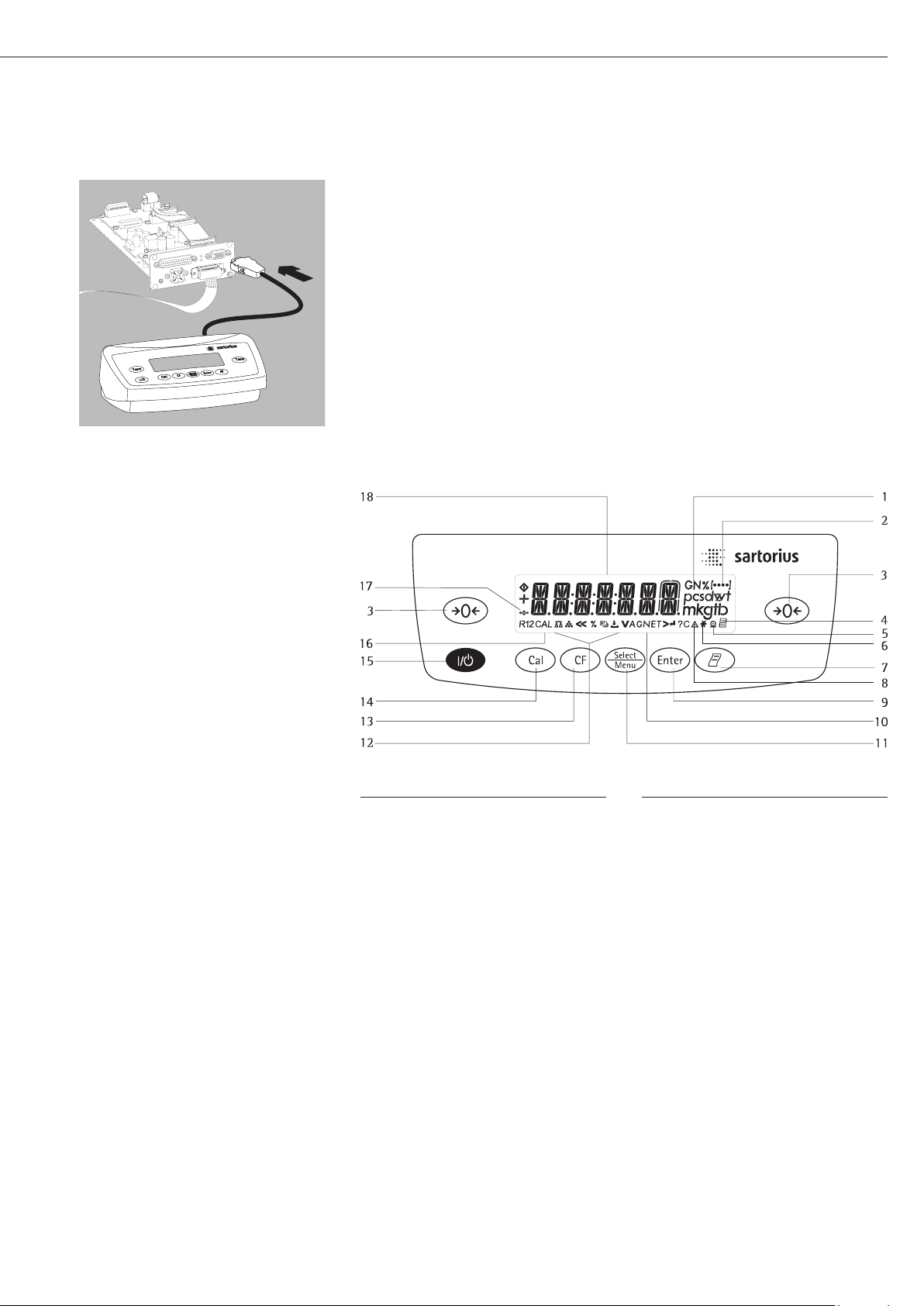
Operation with the Optional YAC01ED Display and Control Unit
Connect the display and control unit to the weigh cell electronic unit using the supplied cable.
Connection cable: 1 meter long with 15-pin D-Sub plug and socket.
Pin 15 is not assigned.
Overview of Display and Control Panel
Position Description
1 Weight units
2 Displays the menu level
3 Tare/Zero
4 Symbol for “GLP printing mode
active”
5 Symbol for “Printing active”
6 Application program active
7 Manual data output:
Press this key to send readout
values to the built-in data
interface.
8 Labeling: not a weight value
9 Start an application program
10 Display: Gross and net value
11 Select an application program |
Open the operating menu
12 Symbols for an active application
(W, Z, L, V, R, A, C)
Position Description
13 Clear Function
This key is generally used to
cancel functions:
– Quit application program
– Cancel calibration/adjustment
routine | Exit menu
14 Start the calibration/adjustment
routine
15 On/off switch
16 Display: calibration/adjustment
function
17 Symbols for zero range
(verified models only)
18 Weight value displayed in
selected weight unit
Symbol:
<< Exit menu
< One menu level higher
V Set menu item
> Select the next sub-item within
a menu level
↵ Confirm menu item
11
Page 12
Basic Weighing Function
Characteristics
– Taring the weigh cell
– Print weight value
Preparation
§ Switch on the weigh cell:
Press the e key
§ Tare the balance/scale if necessary:
Press the w key
$ If necessary, change the configuration
settings:
see “Configuration” on the next page
$ If desired, load the factory settings:
see “Configuration” on the next page
Additional functions:
$ Switching off the weigh cell:
Press the e key
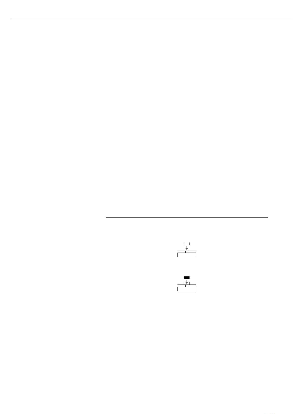
Example
Determine a weight value
Step Press key Display/Printout
1. Switch on the weigh cell
Self-test runs,
followed by automatic initial
tare function.
2. Place container on weighing pan
(in this example 11.5 g).
3. Tare the weigh cell
4. Place sample in container + 132.0 g
(in this example 132 g).
5. Print weight value r N + 132.0 g
(in this example 22 characters)
e 0.0 g
+ 11.5 g
w 0.0 g
12
Page 13

Configuration (Operating Menu)
Purpose
The weigh cell is configured at the
factory. In Setup, you can configure
the weigh cell, i.e. adapt it to individual
requirements.
Characteristics
Parameters are combined into the
following groups
(1st menu level):
1. Weigh cell functions
– Interface
– Record (print)
– Extra functions
2. Application Programs
3. Input
4. Information
5. Language setting
Factory Settings for the Parameters
The factory-set configurations are
identified by an “o” in the list below.
Customer-specific settings can be
configured on request.
Preparation
$ Using the CAS-Suite configuration
software from Sartorius installed on
a PC, you can process the operating
menu parameters as follows:
– Read
– Modify
– Print
– Save
1
)
Configuring of the weigh cell, i.e., adapting it to individual requirements.
Functions of the Keys in the Menu:
Symbol displayed Key Object
V
>
(with cursor right up to 4 menu levels)
b Scroll through menu items
u One menu level lower
↵ u Confirm menu item
c (Press and hold) Save settings and exit menu from any position
<<
<
Indicates menu level
c Save settings and exit menu:
c One menu level higher (left cursor)
or
Using the optional YAC01ED
control unit
1
) Detailed instructions for the available
application programs can be found in
the “ED..., Extend ED Model Range”
operating instructions, which can be
downloaded from the internet at
www.sartorius.com.
Go to Service Center ➝ Downloads.
13
Page 14

Menu Navigation
Example: Setting the Language
Step Press key Display
1. Open the menu:
Display the 1st menu item in the weighing mode
2. Scroll upward within the menu level; Repeatedly press
After the last menu code,
the first code is displayed again (scroll)
3. Select next menu level Press repeatedly English o
(scrolls to the right)
4. Change setting: b English
Select the menu item by scrolling up
5. Confirm setting;
“o” indicates the menu item you have set
6. Go back to the previous menu level
(from menu level 4)
$ If required, select further menu items
7. Save setting Press repeatedly
and exit the menu
or
$ Exit menu without saving changes e
> Restart your application
b long Applic.
Input
b ...
languag.
u
u German
o
c Language
b, u
c
0.0 g
14
Page 15

Menu Structure (Overview)
Level 1 Level 2 Level 3 Codes
Setup BAL.SCAL. AMBIENT conditions (adapt filter) 1. 1. 1.
(Weigh cell functions) App.Filt. Application filter 1. 1. 2.
Stab.Rng. Stability range 1. 1. 3.
STAB. DLY Stability delay 1. 1. 4.
Taring Taring 1. 1. 5
AutoZer. Auto zero 1. 1. 6
Wt.Unit Basic weight unit 1. 1. 7.
Display Display accuracy 1. 1. 8.
Cal./adj. Function of the Q key 1. 1. 9.
Cal.routine 1. 1.10.
Cal.Unit Weight unit for calibration 1. 1.11.
Zero rng. Zero range 1. 1.12.
Zero.on Zero at Power On 1. 1.13.
on.tare Tare/zero at power: 1. 1.14.
Interf. Interface Baudrate 1. 5. 1.
parity Parity 1. 5. 2.
Stopbit Number of stop bits 1. 5. 3.
Handshk. Handshake mode 1. 5. 4.
Databit Number of data bits 1. 5. 5.
dat.rec. SBI (ASCII) or printout 1. 5. 6.
Dat.Rec.(Print) Print (manual/automatic) 1. 6. 1.
Stop automatic printing 1. 6. 2.
Aut.Cycl. Time-dependent autom. Print 1. 6. 3.
tar./prt. Tare bal./scale after ind. print 1. 6. 4.
Prt.Init. Printout of appl. parameters 1. 6. 5.
Format Line format for printout 1. 6. 6.
GLP ISO/GLP-compliant printout 1. 6. 7.
time: 12h/24h 1. 6. 8.
date format 1. 6. 9.
Extras Menu Read only/Can edit 1. 8. 1.
(Additional functions) Horn Acoustic Signal 1. 8. 2.
Keys (Keypad) 1. 8. 3.
Ext.Key External switch function 1. 8. 4.
On Mode Power-on mode 1. 8. 5.
Backlit Display backlighting 1. 8. 6.
Reset Menu Factory settings 1. 9. 1.
Applic. Weigh 2. 1.
Application Unit Toggle Display Display accuracy 2. 2. 2.
programs Counting resolut. ion 2. 3. 1.
Ref.Updt. Automatic reference updating 2. 3. 2.
percentweighing Dec.Plcs Decimal places 2. 4. 1.
net.tot. Net total Comp.Prt. Printout of components 2. 5. 1.
Total Totalizing Comp.Prt. Printout of components 2. 6. 1.
Anim.WG Animal Activty. Animal activity 2. 7. 1.
weighing start 2. 7. 2.
Calc. Calculation Method (Operator) 2. 8. 1.
Dec.Plcs Decimal places 2. 8. 2.
Density determination Dec.Plcs Decimal places 2. 9. 1.
Input Input ID no. ID input; max. 7 characters 3. 1.
InFo Information Version, Ser. No., model Displays software vers., serial no., model 4. 1./.2./.3.
Language English (factory setting) 5. 1.
(Languag.) Deutsch (German) 5. 2.
franc.ais (French) 5. 3.
ital. (Italian) 5. 4.
Espanol (Spanish) 5. 5.
PyCCK
Polski (Polish) 5. 7.
codes Menu shows codes (not texts) 5. 8.
(Russian) 5. 6.
nn
15
Page 16

Parameter Settings: Overview
ο = Factory setting; √ = User-defined setting
Level 1 Level 2 Level 3 Level 4 Code
1.) Setup Bal.Scal Ambient V.Stable Very stable conditions 1. 1. 1. 1
Weigh cell conditions ο Stable Stable conditions 1. 1. 1. 2
functions (Filter adaptation) Unstabl Unstable conditions 1. 1. 1. 3
V.Unstbl. Very unstable conditions 1. 1. 1. 4
App.Filt. ο FINAL.RD. Final readout mode 1. 1. 2. 1
Application filter Filling Filling mode 1. 1. 2. 2
reduc. Reduced 1. 1. 2. 3
off 1. 1. 2. 4
Stab.Rng. 1/4 dig.it (digit) 1. 1. 3. 1
Stability range 1/2 dig.it (digit) 1. 1. 3. 2
1 dig.it (digit) 1. 1. 3. 3
ο 2 dig.it (digits) 1. 1. 3. 4
4 dig.it (digits) 1. 1. 3. 5
8 dig.it (digits) 1. 1. 3. 6
Stab. Stability No delay 1. 1. 4. 1
delay ο Short delay 1. 1. 4. 2
Medium delay 1. 1. 4. 3
Long delay 1. 1. 4. 4
Taring W/o Stb W/o stability 1. 1. 5. 1
Taring ο W/ StAb After stability 1. 1. 5. 2
Aut.zero off 1. 1. 6. 1
Auto zero ο on 1. 1. 6. 2
Wt.Unit Free unit 1. 1. 7. 1
Basic weight unit ο Gram
Units: Kilogram to Newton 1. 1. 7. 3 to 1. 1. 7.23
Basic accuracy ο all 1. 1. 8. 1
Display accuracy Minus 1 One level lower 1. 1. 8. 2
Increment of the measured values one level lower 1. 1. 8. 3
Increment of the measured values two levels lower 1. 1. 8. 4
Increment of the measured values three levels lower 1. 1. 8. 5
Incrm. 1 Last digit single increment 1. 1. 8. 6
Resolution by a factor of 10 1. 1. 8. 8
Cal./Adj. ο EXT.Cal. External calibr./adjustment with factory-set weight 1. 1. 9. 1
Function of the Cal.e.usr. External calibr./adjustment with user-defined weight 1. 1. 9. 3
cal.int. Internal calibr./adjustment 1. 1. 9. 4
Q key lin.ext. External linearization with factory-set weights 1. 1. 9. 6
lin.e.usr. External linearization with user-defined weights 1. 1. 9. 7
set.pre. Setting the preload 1. 1. 9. 8
clr.preload Clear preload 1. 1. 9. 9
blocked Q blocked 1. 1. 9. 11
Cal.routine ο Sequence adjustment 1. 1. 10. 1
CAL.ADJ. Adjustment as needed 1. 1. 10. 2
Cal.Unit ο Gram 1. 1. 11. 1
Weight unit Kilogr. Kilograms 1. 1. 11. 2
for calibration Pounds 1. 1. 11. 3
Zero rng. default. (factory-set) 1. 1. 12. 1
Zero range 2 Perc.ent 1. 1. 12. 2
5 Perc.ent 1. 1. 12. 3
ο 10 Perc.ent 1. 1. 12. 4
Int.zero Zero at power-on default (factory-set) 1. 1. 13. 1
Power On Initial zero 2%/max. cap 1. 1. 13. 2
Initial zero 5%/max. cap 1. 1. 13. 3
ο Initial zero 10%/max. cap 1. 1. 13. 4
Initial zero 20%/max. cap 1. 1. 13. 5
Initial zero 50%/max. cap 1. 1. 13. 6
Initial zero 100%/max. cap 1. 1. 13. 7
on.tare Off 1. 1. 14. 1
(Tare/Zero at Power/ ο On 1. 1. 14. 2
Zero-setting range)
Output rate ο Normal 1. 1. 15. 1
Fast (five times faster) 1. 1. 15. 2
16
1. 1. 7. 2
Page 17

Level 1 Level 2 Level 3 Level 4 Code
Setup Interf. Baudrate 600 1. 5. 1. 3
Interface ο 1200 1. 5. 1. 4
2400 1. 5. 1. 5
4800 1. 5. 1. 6
9600 1. 5. 1. 7
19200 1. 5. 1. 8
38400 1. 5. 1. 9
Parity ο Odd 1. 5. 2. 3
Parity Even 1. 5. 2. 4
None (no parity) 1. 5. 2. 5
stop bit Number ο 1 Stop 1. 5. 3. 1
of stop bits 2 stop 1. 5. 3. 2
Handshk. Softw.are 1. 5. 4. 1
Handshake ο Hardw.are 1. 5. 4. 2
Operating mode None 1. 5. 4. 3
data bit Number ο 7 bits 1. 5. 5. 1
of data bits 8 bits 1. 5. 5. 2
dat.rec. Com- ο Sartorius SBI (ASCII) 1. 5. 6. 1
munication mode printer (GLP-compliant record) 1. 5. 6. 2
Sartorius XBPI 1. 5. 6. 4
dat.rec. print Manual without stability 1. 6. 1. 1
(Printout) (manual/ ο man.with. stability 1. 6. 1. 2
automatic) auto.w/o. stability 1. 6. 1. 3
Aut.With stability 1. 6. 1. 4
Ld.Chnge Autom. after load change 1. 6. 1. 5
Stop ο Off Not possible 1. 6. 2. 1
autom. printing On Cancel with r 1. 6. 2. 2
Aut.Cycl. ο EACHVAL (1 display update) 1. 6. 3. 1
Time-dependent AFTR.2 (2 display updates) 1. 6. 3. 2
autom. printing
tar./prt. ο off 1. 6. 4. 1
Tare bal./scale on 1. 6. 4. 2
after ind. print
17
Page 18

Level 1 Level 2 Level 3 Level 4 Code
Setup dat.rec. Prt.Init. Print- Off 1. 6. 5. 1
printout out of application ο all All parameters 1. 6. 5. 2
(Printout) parameters mainpar. Main parameters 1. 6. 5. 3
Format Line ο 16. char. characters (w/o ID) 1. 6. 6. 1
format for 22. char. characters (w/ ID) 1. 6. 6. 2
printout 2nd line with date/time 1. 6. 6. 3
GLP printout ο Off 1. 6. 7. 1
As ISO/GLP-com- Cal.-adj. Only for calib./adj. 1. 6. 7. 2
pliant Printout Always on 1. 6. 7. 3
Time ο 24h display 1. 6. 8. 1
12h display “AM/PM” 1. 6. 8. 2
Date ο dd.mmm.yy format 1. 6. 9. 1
mmm.dd.yy format 1. 6. 9. 2
Extras menu ο Can Edit 1. 8. 1. 1
(Additional Rd. Only Read only 1. 8. 1. 2
functions)
Horn Acoustic Off 1. 8. 2. 1
Signal ο On
1. 8. 2. 2
Keys ο free 1. 8. 3. 1
(Keypad) blocked 1. 8. 3. 2
ext.key ο Print key r 1. 8. 4. 1
External switch Z/Tare w key 1. 8. 4. 2
function cal. Q key 1. 8. 4. 3
select b key 1. 8. 4. 4
cf c key 1. 8. 4. 5
enter u key 1. 8. 4. 6
blocked Key locked 1. 8. 4. 9
on mode off/on Off/on/standby 1. 8. 5. 1
Power-on mode standby On/standby 1. 8. 5. 2
ο Auto On Auto on 1. 8. 5. 3
Backlit off 1. 8. 6. 1
Display ο on 1. 8. 6. 2
backlighting
Reset Menu Yes Restore fcty. settings 1. 9. 1. 1
Reset menu Factory settings ο no Do not restore settings 1. 9. 1. 2
18
Page 19

Application Program Configuration:
Level 1 Level 2 Level 3 Level 4 Code
Applic. weigh 2. 1.
Application
programs
1
) Unit 2. WT.unit Free unit 2. 2. 1. 1
Toggling ο Gram 2. 2. 1. 2
Units: Kilogram to Newton 2. 2. 1. 3
to
2. 2. 1. 23
Basic accuracy ο all 2. 2. 2. 1
Display accuracy Minus 1 One level lower 2. 2. 2. 2
Increment of the measured values one level lower 2. 2. 2. 3
Increment of the measured values two levels lower 2. 2. 2. 4
Increment of the measured values three levels lower 2. 2. 2. 5
Incrm. 1 Last digit single increment 2. 2. 2. 6
Counting resolut. ο Disp.dig. Display accuracy 2. 3. 1. 1
10 fold 10 times > disp. 2. 3. 1. 2
Ref.Updt. ο off 2. 3. 2. 1
Auto. Reference autom.atically 2. 3. 2. 2
updating
Percent Dec.plcs none No decimal places 2. 4. 1. 1
Weighing Decimal places ο 1 dec.pl. 1 decimal place 2. 4. 1. 2
in Percent 2 Dec.Pl. 2 decimal places 2. 4. 1. 3
3 Dec.Pl. 3 decimal places 2. 4. 1. 4
net.tot. comp.prt. off 2. 5. 1. 1
Net total Component ο On 2. 5. 1. 2
printout
total comp.prt. off 2. 6. 1. 1
Totalizing Component ο On 2. 6. 1. 2
printout
Anim.WG activty. calm (fluct.: 2% of test obj.) 2. 7. 1. 1
Animal Animal activity ο active (fluct.: 5% of test obj.) 2. 7. 1. 2
weighing v.active (fluct.: 20% of test obj.) 2. 7. 1. 3
start manual 2. 7. 2. 1
ο auto. Automatic 2. 7. 2. 2
Calc. Method ο Mul. Multiplier 2. 8. 1. 1
Calculation (operator) div. Divisor 2. 8. 1. 2
Dec.plcs none No decimal places 2. 8. 2. 1
Decimal places ο 1 dec.pl. 1 decimal place 2. 8. 2. 2
2 Dec.Pl. 2 decimal places 2. 8. 2. 3
3 Dec.Pl. 3 decimal places 2. 8. 2. 4
Density dec.plcs none No dec. places 2. 9. 1. 1
determination Decimal places ο 1 dec.pl. 1 decimal place 2. 9. 1. 2
1
) If you need more detailed information on application programs:
Please contact your local Sartorius dealer.
19
Page 20

Configuration Operation
(Setup)
Purpose
Weigh cells are equipped with an interface
port for connection to a computer or other
peripheral device.
PC
You can connect a computer to change,
start and/or monitor functions and
application programs.
Characteristics
Type of interface: Serial interface
Interface operating mode: Full duplex
Level: RS-232
Transmission rate:
600, 1200, 2400, 4800, 9600, 19,200 and
38,400 baud
Parity: Odd, even, none
Number of data bits: 7 or 8 bits
Character transmission:
Start bit, 7-bit ASCII, parity,
1 or 2 stop bits
Handshake:
For 2-wire interface:
Software (XON/XOFF) or none
For 4-wire interface:
Hardware (CTS/DTR) or none
Data output of balance/scale:
16 or 22 characters
Factory Setting of the Parameters
Transmission rate:
1200 baud (Code 1. 5. 1. 4)
Parity: odd Odd (1. 5. 2. 3)
Stop bits: 1 Stopbit (1. 5. 3. 1)
Handshake:
Handsk. Hardware handshake (1. 5. 4. 2)
Communication mode: sbi (1. 5. 6. 1)
Printing: man.with Manual after stability
(1. 6. 1. 2)
Output Format with 16 Characters (Compatibility with Current Weigh Cells)
Display segments that are not activated are output as spaces.
The type of character that can be output depends on the character‘s position:
Position 1 2 3 4 5 6 7 8 9 10 11 12 13 14 15 16
+ A A A A A A A * E E E CR LF
or – . . . . . . . * * *
or * * * * * * * * *
*: Space CR: Carriage return
A: Displayed characters LF: Line feed
E: Unit symbol . : Decimal point
Special Codes
Position 1 2 3 4 5 6 7 8 9 10 11 12 13 14 15 16
* * * * * * * * * * * * * * CR LF
or H i g h
or L o w
or C a l . E x t .
*: Space High: Overload
Cal. Ext.: Adjustment, external Low: Underweight
Error message
Position 1 2 3 4 5 6 7 8 9 10 11 12 13 14 15 16
E r r * # # # * * * * CR LF
A P P . E R R
D I S . E R R
P R T . E R R
*: Space # # #: Error code number
1
) For cause and solution, please refer to the “Troubleshooting Guide”
1)
* * * * CR LF
1)
* * * * CR LF
1)
* * * * CR LF
Preparation
See “Pin Assignments” and
“Pin Assignment Chart”
20
Page 21

Example: Output of the weight value + 123.56 g
Position 1 2 3 4 5 6 7 8 9 10 11 12 13 14 15 16
+ * * * 1 2 3 . 5 6 * g * * CR LF
+ * * 1 2 3 . 5 [ 6 ]
1
) g * * CR LF
Position 1: Plus or minus sign or space
Position 2: Space
Position 3 - 10: Weight value with decimal point; leading zeros are output as spaces.
Position 11: Space
Position 12 - 14: Characters for unit of measure or space
Position 15: Carriage return
Position 16: Line feed
Output Format with 22 Characters (Compatibility with Current Weigh Cells)
When data is output with an ID code, the 6-character code precedes the 16-character string described above.
These six characters identify the subsequent value.
1 2 3 4 5 6 7 8 9 10 11 12 13 14 15 16 17 18 19 20 21 22
K K K K K K + * A A A A A A A A * E E E CR LF
* * * * * – . . . . . . . . * * *
* * * * * * * * *
K: ID code character E: Unit symbol
*: Space CR: Carriage return
A: Displayed characters LF: Line feed
Example:
1 2 3 4 5 6 7 8 9 10 11 12 13 14 15 16 17 18 19 20 21 22
N + 1 2 3 . 5 6 * g * * CR LF
N + 1 2 3 . 5 [ 6 ]
1
) g * * CR LF
SBI mode:
When the SBI mode is active (menu code 1. 5. 6. 1), non-verified display digits are not automatically marked. Please take the corresponding
measures or adjust the settings on the peripheral device.
Special Codes
1 2 3 4 5 6 7 8 9 10 11 12 13 14 15 16 17 18 19 20 21 22
S t a t * * * * * * * * * * * * * * * * CR LF
H i g h
L o w
C a l . E x t .
*: Space High: Overload
Cal. Ext.: Adjustment, external Low: Underweight
Error message
1 2 3 4 5 6 7 8 9 10 11 12 13 14 15 16 17 18 19 20 21 22
S t a t * * * * * E R R * # # # * * * * CR LF
S t a t * * * * * A P P . E R R
S t a t * * * * * D I S . E R R
S t a t * * * * * P R T . E R R
1)
* * * * CR LF
1)
* * * * CR LF
1)
* * * * CR LF
*: Space # # #: Error code number
1
) For cause and solution, please refer to the “Troubleshooting Guide”
21
Page 22

Commands (Data Input Format Compatible with Current Weigh Cells)
The computer connected via the data port can send commands to the weigh cell for controlling functions. The commands sent are control
commands and may have different formats. Control commands consist of up to 13 characters. Each character must be transmitted according
to the settings configured in the operating menu for data transmission.
Formats for Control Commands
Format 1: Esc ! CR LF
Format 2: Esc ! # _ CR LF
Esc: Escape (optional) CR: Carriage return
!: Command character LF: Line feed (optional)
_: Underline
Command character Format 1:
! Meaning
K Ambient conditions: very stable
L Ambient conditions: stable
M Ambient conditions: unstable
N Ambient conditions: very unstable
O Block keys
P Key r (print, auto print; activate or block)
1
)
Q Acoustic signal
R Unblock keys
S Restart | Self-test
T Tare | Zero: Key “w”
U Tare
V Zero
W Calibrate | Adjust depending on menu setting
Z Perform internal calibration/adjustment
2
)
Command character Format 2:
!# Meaning
f0_ Function key
b
f1_ Function key Q Calibrate | Adjust (depending on the menu setting)
f2_ Function key u
s1_ With »s8_« compatibility: Toggle selection in steps of 1
With »s9_« compatibility: Adjust according to menu setting
s2_ Activate parameter mode (selection)
s3_ Key c
s8_ Compatibility: Consistent with current weigh cells (from 2013)
s9_ Compatibility: Consistent with older weigh cells (previous models)
x0_ Perform internal adjustment
x1_ Print model
x2_ Print serial no.
x3_ Print software version
1
) When initiating the print command, the data output rates may differ: see table on next page.
2
) Only on models with internal weight circuit
22
Page 23

Synchronization
During data communication between
the weigh cell and a connected device
(computer), messages consisting of
ASCII characters are transmitted via the
interface. For error-free data exchange,
parameters for baud rate, parity,
handshake mode and character format
must be identical for both units.
You can set these parameters in the
Setup menu so that they match those
of the connected device. You can also
define parameters in the balance/scale
to make data output dependent on
various conditions. These conditions are
described under each of the application
program descriptions.
No errors are generated just because
no peripheral device is connected to an
interface port (open data port).
Handshake
The weigh cell interface
(Sartorius Balance Interface = SBI)
has transmit and receive buffers.
You can define the different handshake
parameters in the Setup menu of your
weigh cell:
– Hardware handshake (CTS/DTR)
– Software handshake (XON, XOFF)
– No handshake
Software Handshake
The software handshake is controlled via
XON and XOFF. When a device is switched
on, XON must be transmitted to enable
any connected device to communicate.
Data Output by Print Command
The print command can be transmitted by
pressing r or by a software command
(Esc P).
Automatic Data Output
Activate the “Auto Print” operating mode
to have data output to the interface port
without a print command. You can have
synchronized data output automatically
at defined display update intervals, with
or without the stability parameter. The
length of a print interval depends on the
operating menu settings for Ambient
(ambient conditions, menu code 1. 1. 1.
x) and aut.cycl. (time-dependent autom.
printing, menu code 1. 6. 3. x).
If you activate the auto print setting,
data will be transmitted immediately the
moment you turn on the balance/scale.
In the operating menu, you can define
whether automatic printing can be stopped
and started by pressing the “Print” key or
using the interface.
Hardware Handshake
When hardware handshake is
configured on a 4-wire interface,
1 more character can be transmitted
after CTS.
Data Output Rates – Values per Second
Environmental conditions
(filter adaptation) XBPI / SBI “Auto print”
Very stable (1.1.1.1) 20 20
Stable (1.1.1.2) 10 10
Unstable (1.1.1.3) 5 5
Very unstable (1.1.1.4) 2.5 2.5
23
Page 24

Data Interface: Compatibility with Older Weigh Cells (Previous Models)
Once command »ESC s9_« has been
sent, data input and data output behave as in the earlier Sartorius WZ-/WZA
weigh cells (previous models).
Data Output Format
In operating mode »SBI«,
16 characters are printed out.
Example:
+ 253 pcs
Data Output Format with 16 Characters
Characters that are displayed blank are printed as spaces. Display values without a decimal
point are output without a decimal point.
The type of character that can be output depends on the character‘s position:
Normal Operation
Position 1 2 3 4 5 6 7 8 9 10 11 12 13 14 15 16
+ A A A A A A A A A * E E E CR LF
or – . . . . . . . . . * * *
or * * * * * * * * * *
*: Space
A: Digits of measurement value
E: Unit symbol
CR: Carriage return
LF: Line feed
24
Page 25

Special Codes
Position 1 2 3 4 5 6 7 8 9 10 11 12 13 14 15 16
* * * * * * – – * * * * * * CR LF
or H H
or L L
or C
*: Space
– –: Final readout
H: Overload
H H: Overload in checkweighing
(Function is only available during operation with following peripheral devices:
Optional display unit or software YAD01IS)
L: Underweight
L L: Underweight in checkweighing
C: Adjustment
Error Messages
Position 1 2 3 4 5 6 7 8 9 10 11 12 13 14 15 16
* * * E r r * # # # * * * * CR LF
*: Space
# # #: Error number
Example: Output of the weight value + 1255.7 g
Position 1 2 3 4 5 6 7 8 9 10 11 12 13 14 15 16
+ * * * 1 2 5 5 . 7 * g * * CR LF
Position 1: Plus +, minus –, or space
Position 2: Space
Position 3 - 10: Weight value with decimal point; leading zeros are printed as spaces
Position 11: Space
Position 12 - 14: Characters for unit of measure or space
Position 15: Carriage return
Position 16: Line feed
Data Input Format
A computer connected via the data port can send commands to the device to control device
functions.
The commands sent are control commands and may have different formats.
Control commands have up to 26 characters. Each of these characters must be
sent based on the setup configuration for data transmission.
Formats for Control Commands
Format 1: Esc ! CR LF
Format 2: Esc ! # _ CR LF
Esc: Escape !: Command character
#: Number
_: Underscore (ASCII: 95)
CR: Carriage return (optional)
LF: Line feed (optional)
max: Depending on the command character, i.e. parameter: The entry is truncated after
the max. length, and not rejected as when entered via the keyboard
Format 1 (e.g., ESC K)
! Meaning
K Filter adjustment:
Very stable conditions
L Filter adjustment: Stable conditions
M Filter adjustment:
Unstable conditions
N Filter adjustment:
Very unstable conditions
O Lock keys
Q Acoustic signal (beep)
P Print
R Release keys
S Restart
T Tare and zero
Z Internal adjustment
Format 2 (e.g., ESC f3_)
!# Meaning
f1_ Calibrate or Adjust according to
menu setting
f3_ Zero
f4_ Tare (without zeroing)
s1_ External adjustment
s3_ Function [CF]
x0_ Perform internal calibration
x1_ Print load cell type
x2_ Print load cell series no.
x3_ Load cell software version
25
Page 26

Pin Assignment Chart
Female Interface Connector:
25-pin D-Submini (DB25S) with screw lock hardware
Required Male Connector (Recommended):
25-pin D-Submini, DB25S, with integrated shielded cable clamp and shield plate assembly
(Amp type 826 985-1C) and fastening screws (Amp type 164 868-1)
! Warning When Using Pre-wired RS-232 Connecting Cables:
The pin assignments in RS-232 cables purchased from other manufacturers may be incompatible with Sartorius weighing instruments.
Be sure to check the pin assignments against the chart below before connecting the cable, and disconnect any lines identified differently
from those specified by Sartorius (e.g., pin 6).
Failure to do so may cause malfunction, damage or even completely ruin your balance/scale and/or peripheral device(s).
Pin Assignments:
Pin 1: Signal Ground
Pin 2: Data Output (TxD)
Pin 3: Data Input (RxD)
Pin 4: Internal Ground (GND)
Pin 5: Clear to Send (CTS)
Pin 6: Not used
Pin 7: Internal Ground (GND)
Pin 8: Internal Ground (GND)
Pin 9: Not used
Pin 10: Not used
Pin 11: +12 V (operating voltage
for Sartorius printer)
Pin 12: Reset _ Out
Pin 13: +5 V
Pin 14: Internal Ground (GND)
Pin 15: Universal remote switch
Pin 16: Not used
Pin 17: Not used
Pin 18: Not used
Pin 19: Not used
Pin 20: Data Terminal Ready (DTR)
Pin 21: Not used
Pin 22: Not used
Pin 23: Not used
Pin 24: Not used
Pin 25: +5 V
1
) For remote switch 2)
1
) = Hardware restart
2
) = External switch function can be programmed in the Setup: EXTRAS : EXT.key (1.8.4.x)
26
Page 27

Cabling Diagram
Balance/scale Computer,
25-pin 25-contact
male connector female connector
TxD 2 3
R
xD 3 2
CTS 5 20
DTR 20 5
GND 4/7 6
GND 14 7
Balance/scale Computer,
25-pin 9-contact
male connector female connector
TxD 2 2
R
xD 3 3
CTS 5 4
DTR 20 8
GND 4/7 6
GND 14 5
For connecting a computer or other peripheral device to the balance/scale using
the RS-232C/V24 protocol and cable lengths of up to 15 m (approx. 50 ft).
No other pins of the balance/scale may be assigned!
Cable type: AWG 24 specification
27
Page 28

Models WZA…-L: Extension Cords between Weigh Cell and Electronics PCB
Pos.: Name: Manufacturer: Manufacturer#: Internal article #: Cutting length: Quantity: Approvals/Comments:
10 Male connector, 15-pin, D-SUB IDC free 1+ lowcost
20 Ribbon cable, 10 p. AWG28 color-coded 3M 3302-10 57001-368-01 500 mm 1+ UL-File#: E42769
30 Male connector, 10-pin, IDC 3M 4610-6051 010800 1+ UL-File#: E68080
Model WZA224-LC: Extension Cord between Weigh Cell and Electronics PCB
Assignment:
Pos.: Name: Manufacturer: Manufacturer: Internal article #: Cut length: Quantity: Approvals/Notes:
10 Cable ribbon, AWG28 15-pin gray 3M 3365 57001-318-01 500 mm 1+ UL file no. E42769
20 Male connector, D-SUB 15-pin IDC 54101-020-01 1+
30 Male connector, 10-pin IDC 3M 4610-6051 010800 1+ UL file no. E68080
40 Pin strip, 5-pin solder JST B5B-XH-A 57002-151-01 1+ or 57001-883-01
50 Shrink tubing 2.4 + 1 2 31335-202-02 5+
UL recognized E60389
! The user can create this cable himself/herself. The ambient conditions must be non-critical.
28
Page 29

Error Messages
Error codes are displayed for about 2 seconds. The program then returns automatically to the weighing mode.
Display Cause Solution
high or Err 55 Weighing capacity exceeded Unload the weighing pan
low or Err 54 Contact between load plate and environment, Move the object that is touching the weighing pan
load on weighing pan too light
App.err. Cannot store data: Increase load
Load on weighing pan too light or no
sample on pan while application is active
dis.err. Data output not compatible Change the configuration with output format in the
with output format operating menu
prt.err. Data interface for Reset the menu factory settings
printer output blocked or
Contact your local Sartorius Service Center
err 02 Calibration parameter not met,
e.g.:
– Unstable Correct the setup conditions
– Tare Calibrate only when zero is displayed
– Load on weighing pan Unload the balance/scale
err 10 “Tare” function is locked for Clear the tare memory to unlock the “Tare” function
active application program
“Net total”;
Only 1 tare function can be used at a time
Err 11 Tare memory not allowed: Carry out “Tare” function
err 03 Zero point error at the end of calibration Check installation conditions, note warm-up time
err 06 Int. calibration weight faulty or not available Service
err 08 <> Zero range Error during zeroing (value outside 2%) Repeat process
err 09 < 0 not allowed Error during taring (tare value <0) Repeat process
err 19 Preload is too high The preload to be applied is too high Change the preload value
err 30 The balance/scale is in BPI mode With service tool – carry out “close” function
err 50 or 53 TC converter failure Service
err 241 Checksum error Service
err 243 Checksum error Carry out menu reset
err 245 or 247 Checksum error Calibration/Adjust the balance/scale
err 249 Checksum error Service
The weight readout changes constantly Unstable ambient conditions Setup location unstable
(excessive vibration or draft) Adjust Setup configuration
Foreign object is caught between Remove the foreign object
weighing pan and balance/scale housing
Repeat calibration
The weight readout is obviously wrong The balance/scale was not calibrated/adjusted Adjustment
Balance/scale was not tared before weighing Tare
If any other errors occur, contact your local Sartorius Service Center.
For contact information go to: http://www.sartorius.com
29
Page 30

Overview
Specifications
Standard specifications Customer-specific
modifications
Model WZA224-LC WZA224-L WZA54-L WZA523-L WZA8202-L
Technology EMFR EMFR EMK EMFR EMFR
Weighing Capacity g 220 220 50 520 8200
Readability g 0.0001 0.0001 0.0001 0.001 0.01
Required preload on the load receptor g 10 10 5 30 350
Tare range (subtractive) g over entire weighing range
Repeatability (standard deviation)
Linearity <±g 0.0002 0.0002 0.0005 0.002 0.02
Measurement time
3
) s 0.6 0.6 0.8 0.6 0.6
Adaptation to ambient conditions By selection of 1 of 4 optimized filter levels
Operating temperature range °C +10…+30 °C
Allowable ambient operating temperature °C +5…+40 °C
Sensitivity drift within +10… +30 °C <±/K 1 · 10
External calibration weight g 50 (E2) 50 (E2) 10 (E2) 200 (F1) 2000 (F1)
(min accuracy class)
Net weight, approx. kg 2.2 1.15 0.62 1.15 1.15
Power supply VDc min. 12 … 26 max., optimal 15 V (+15% to –10%)
Ripple 50/60 Hz VDc 0.5 Vpp (voltage peak-to-peak)
Power consumption 3.4 W average
Switch-on current 6 W average (weigh cell only)
Built-in interface RS-232C-S/V24-V28; 7-bit; even, mark, odd, space;
Transmission rates: 150 to 19200 baud,1 or 2 stop bits; software/hardware handshake
1
) <±g 0.0001 0.0001 0.0002 0.001 0.01
-6
1 · 10-6 1 . 10-6 2 · 10-6 2 · 10
-6
1
) = Depends on system design
2
) = For operation with greater preload setting, please send e-mail to request PC configuration software; e-mail address: fast.factory@sartorius.com
Greater preloads are possible, but reduce the weighing capacity.
3
) = The weighing time is the time period in which the measured value oscillates within a range of ±3x the standard range of the static end value.
Test weight approx. 25% of max.
30
Page 31

Dimensions (Scale Drawings)
Weigh Cell Model:
WZA224-LC
All dimensions are given in millimeters
31
Page 32

Dimensions (Scale Drawings)
Weigh Cell Model:
WZA224-L
208
All dimensions are given in millimeters
32
Page 33

Dimensions (Scale Drawings)
Weigh Cell Model:
WZA54-L
All dimensions are given in millimeters
33
Page 34

208
Dimensions (Scale Drawings)
Weigh Cell Model:
WZA523-L
All dimensions are given in millimeters
34
Page 35

Dimensions (Scale Drawings)
(3x)
Weigh Cell Models:
WZA8202-L
All dimensions are given in millimeters
for countersunk screw M3
35
Page 36

Accessories
Product Order No.
Display and control unit with cable (0.9 m)
for connection to enclosed electronics module YAC01ED
Configuration software for settings,
calibration/adjustment and setting the preload Cubis CAS Suite
SartoConnect data transfer software (for loading
weight values in a PC running Windows® 95/98/NT
and direct processing with application programs
such as Excel, Access, etc.) incl. adapter cable
(1.5 m) from weigh cell to PC (12-pin to 9-pin) YSC01I
Data cables RS-232
– for PC connection, 25-pin 7357312
– for PC connection, 9-pin 7357314
AC adapter
IP40 protection in accordance with VDE* 0470/529
– Europe 6971886 or
– USA, Canada, Japan 6971984 + 6971954
– GB 6971984 + 6971955
– Australia, New Zealand 6971984 + 6971956
– South Africa 6971984 + 6971957
– India 6971984 + 6971964
Additional options and accessories available on request
6971984 + 6971953
* VDE = Verband der Elektrotechnik, Elektronik, Informationstechnik
(Association for Electrical, Electronic & Information Technologies)
36
Page 37

37
Page 38

Formular: Rücklieferung
Form: Return delivery
Bitte dieses Formular dem Gerät beilegen
Please attach this form to the instrument
being returned
Zu beachten! Important Note!
Um eine Gefährdung unserer Mitarbeiter
durch Kontaminationen ausschließen zu können,
ist eine Bearbeitung nur mit ausgefüllter
Dekontaminationserklärung möglich.
An | To: Von | From:
Sartorius Lab Instruments GmbH & Co. KG
Servicezentrum
Weender Landstraße 94–108
37075 Göttingen
Germany
Typ | Model Serien-Nr. | Serial no. Kunden-Nr. | Customer no.
Rücklieferungsnummer / Meldungsnummer
Goods return number / Registration number
To protect our employees from health hazards
due to contamination, we will only accept return
products if we have a completely filled out
Declaration about Decontamination.
Page 1 of 1
Zubehör | Accessories Bestell-Nr. / Rechnungs-Nr. | Order no. / Invoice no
Informationen zur Rücksendung | Informations on return delivery
Produkt defekt | Product defective:
Lieferung unvollständig | Delivery incomplete:
Falschlieferung | Wrong delivery:
Konsignationsgerät | Goods on consignment:
Anderer Grund | Other reason:
Nach Reparatur ins Fertiglager
Return to stock after repair
Nach Reparatur zurück an Absender
Return to sender after repair
Nach Reparatur ins 2.Wahl-Lager
Return to second hand stock after repair
Entsorgen | Scrap
.
Kostenvoranschlag an | Quotation to:
Weiterleiten an | Forward to:
Information an | Information to:
Sonstiges / Bemerkungen | Other / Remarks:
Kontaktperson | Contact personTel.-Nr. | Phone no.Fax-Nr. | Fax no. Kostenstelle | Cost Center
Datum | Unterschrift (Kontaktperson)
Date | Signature (Contact person)
Genehmigt | Datum | Unterschrift
Approved | Date | Signature
38
Page 39

Declaration about decontamination
Declaration about decontamination and cleaning of equipment and components
To protect our personnel, we require all equipment or components be free of biological, chemical, or radioactive
contaminants. We will only accept such equipment or components when:
t the equipment or components have been adequately CLEANED and DECONTAMINATED.
t
this declaring document has been completed, signed and returned by an authorized person.
Please help us in assuring a safe, hazard-free work environment.
Description of the Equipment or Component(s)
Description / Cat. No.:
Serial no.:
No. of invoice/delivery note
Date of delivery:
Contamination / Cleaning
Attention: Please specify exactly the biological,
chemical, or radioisotopic contaminant.
The equipment was contaminated with: and it has been cleaned and decontaminated by
Attention: Please describe the cleaning and
decontamination procedure/method.
Legally binding declaration
This is to certify that all information given in this form is correct and complete.
The equipment and components have been adequately decontaminated and cleaned according to the legal
requirements. No chemical or biological or radioactive risks remain that can endanger exposed persons‘ safety or
health.
Company / Institute:
Address / Country:
Tel.: Fax (with area code):
Name of the authorized person:
Position:
Signature / Date:
Please pack the equipment properly and send it to your
local service representative.
Please refer to our website (www.sartorius.com)
or contact the Sartorius Service Center for more
detailed information regarding repair service
addresses of your device.
39
Page 40

Last updated:
The information and figures contained in these
instructions correspond to the version date
specified below.
Sartorius reserves the right to make changes
to the technology, features, specifications and
design of the equipment without notice.
Masculine or feminine forms are used to
facilitate legibility in these instructions and
always simultaneously denote the other
gender as well.
Copyright notice:
This instruction manual, including all of its
components, is protected by copyright.
Any use beyond the limits of the copyright law
is not permitted without our approval.
This applies in particular to reprinting,
translation and editing irrespective of the type
of media used.
© Sartorius Germany
Sartorius Lab Instruments GmbH & Co. KG
Otto-Brenner-Strasse 20
37079 Goettingen, Germany
Phone:
+49.551.308.0
Fax:
www.sartorius.com
+49.551.308.3289
04 | 2016
Printed in the EU on paper bleached
without chlorine. | W
Publication No.: WWZ6011-d160408
 Loading...