

Page 1

85030-519-25
Directions for Use
Vivaflow 50 | 50R | 200
Page 2

2 |
Contents
Vivaflow 50 3
Single Module 3
Linked Modules 4
Diafiltration|Desalting 5
Concentration 6
Recovery 6
System Components 7
Technical Specifications 7
Performance Characteristics 8
Ordering Information 9
Chemical Compatibility 10
Vivaflow 50R and Vivaflow 200 11
Operation of Single Module 11
Operation of Two Modules 12 – 13
Diafiltration|Desalting 14
Concentration 14
Recovery 14
Technical Specifications 15
Cleaning 16
Storage 16
Performance Characteristics 17 – 18
Ordering Information 19 – 20
Chemical Compatibility 21
Page 3
| 3
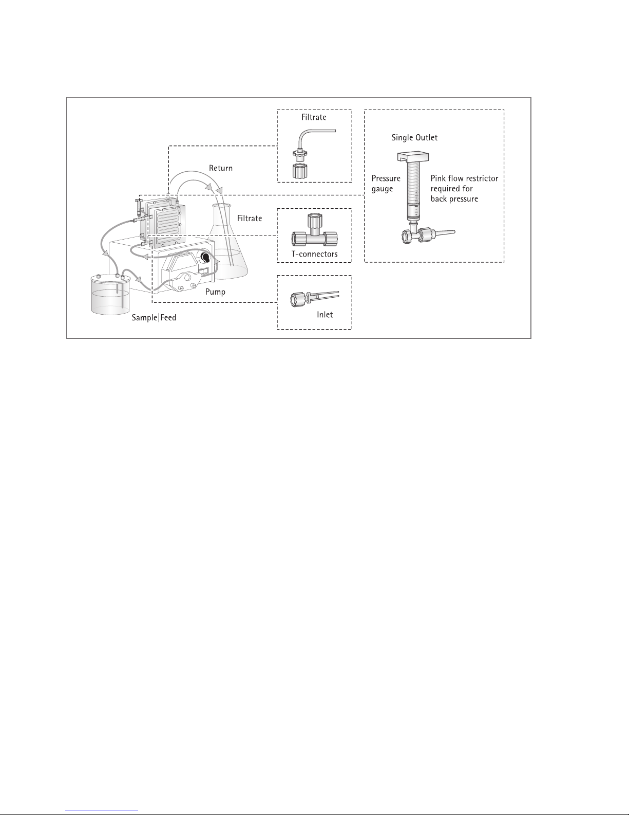
Vivaflow 50
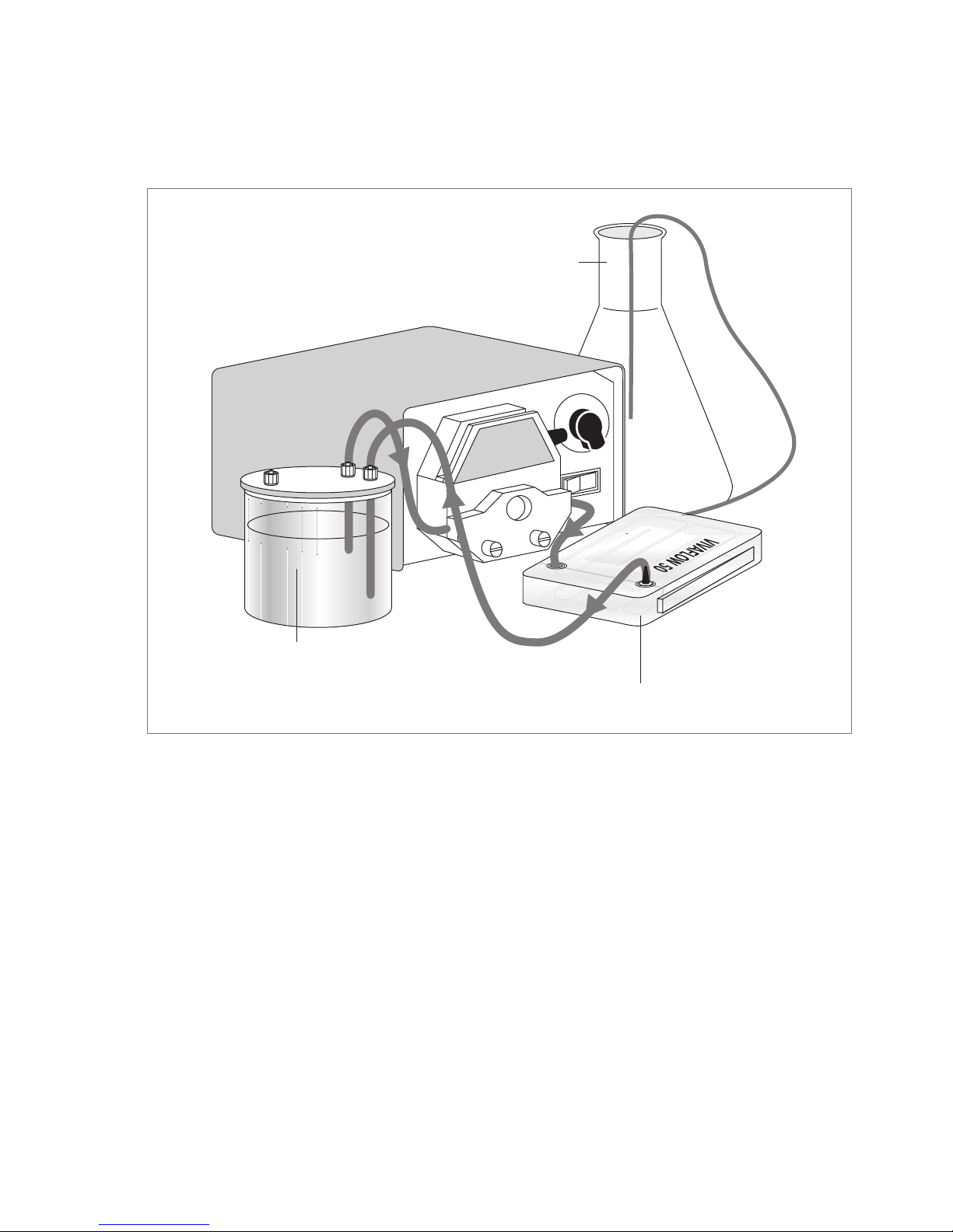
Single module
1. Set up the system as illustrated in
Diagram 1. Note the positioning of the
flow restrictor on the return line.
2. Vivaflow membranes contain trace
amounts of glycerine and sodium azide.
To remove these chemicals and to check
the security of the tube connections,
it is recommended to rinse the module,
and to test the system at full pressure
before introducing the sample.
3. Place 500 ml deionised water in a suitable
reservoir. The Vivaflow sample|diafiltration reservoir (prod. no. VFA006) is
recommended.
4. Pump liquid through the system to purge
any air pockets. The recirculation rate
should be in the range 200–400 ml/min,
and suitable flow should exit the filtrate
line. If used, the pressure indicator (prod.
no. VFA020), should read approximately
2.5 bar.
5. Allow 400 ml to pass into the filtrate
vessel. Check for any leakage at tubing
connection points. Drain the system
and empty or replace the filtrate vessel,
(see recovery section). The system is now
ready for use.
Filtrate vessel
Sample|diafiltration
reservoir (VFA006)
Pink flow restrictor
Designed for single use only. Anything else constitutes improper use.
Diagram 1: Vivaflow 50 set up
Page 4
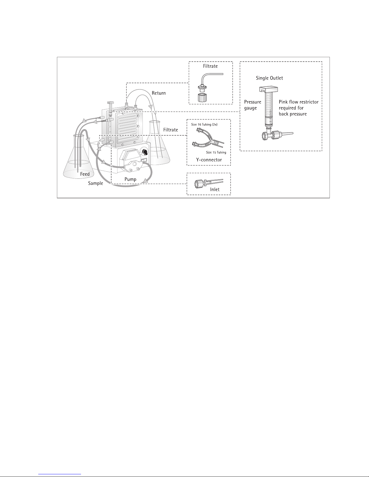
Linked modules
1. Set up the system as illustrated in
Diagram 2. Link the required number of
modules by sliding the tongue and groove
edges together. Note the positioning of
the flow restrictor on the return line.
2. Use series interconnectors, (prod. no.
VFA031), to connect a single row of
modules. Detailed ordering information
for system components to be found of
page 7, Diagram 4.
3. In addition, use T-connectors, (prod. no.
VFA030), to connect two rows of modules
in parallel.
4. The flow path of the system can be configured to suit the membrane|sample
combination. Most solutions are better
suited by modules connected in parallel.
Very low viscosity solutions favour modules connected only in series. Rinse the
system as detailed under single module
operation.
4 |
T-connector
Interconnector
Pressure
indicator
Diagram 2: Setting up multiple Vivaflow 50 cassettes
Page 5
| 5
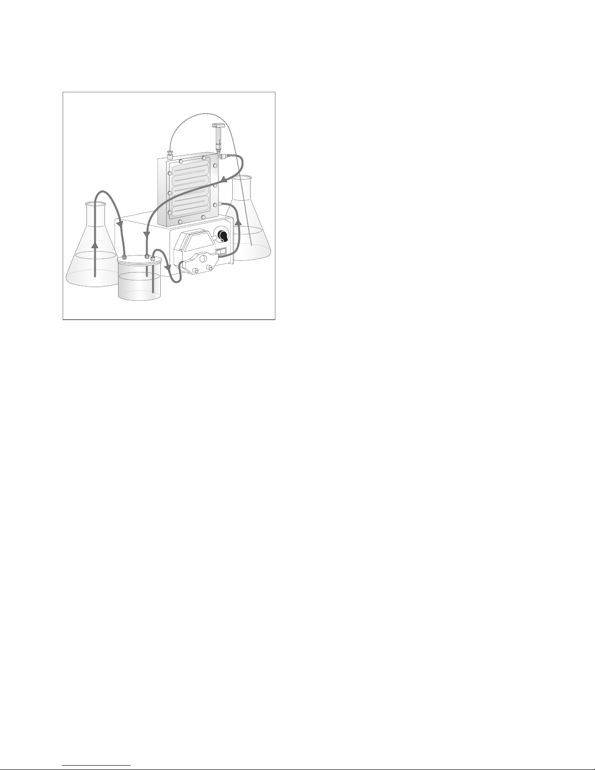
Diafiltration|Desalting
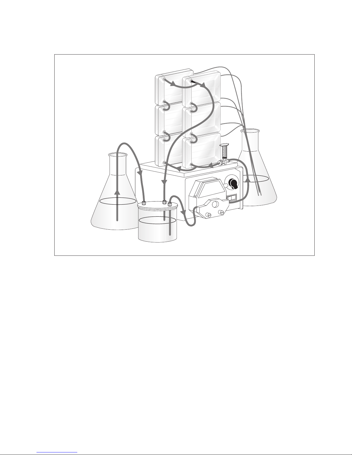
1. Set up the system as illustrated in
Diagram 3 for linked modules. If only
one module is required, connect it in
place of the linked modules.
2. Rinse the system as detailed previously.
3. Either place the solution to be purified in
the 500 ml sample|diafiltration reservoir
(prod. no. VFA006), or concentrate a
larger volume to 500 ml or less so that it
is fully contained in the 500 ml reservoir.
Ensure the reservoir lid is firmly closed.
4. Fill a large feed reservoir with exchange
solvent and pump sample through the
system as for concentration.
5. As the volume in the 500 ml reservoir
decreases, the vacuum created draws
exchange solvent through the feed line
from the larger reservoir. Over 99%
solvent exchange can be accomplished
with an exchange volume approximately
5 times the volume of the sample.
Diagram 3: Buffer exchange | diafiltration with Vivaflow 50
Page 6

6 |
Concentration
1. Fill the feed reservoir with sample solution. When initial volumes larger than
500 ml are required, place 500 ml in
the sample|diafiltration reservoir, the
remaining volume in another suitable container and connect the vessels
as detailed in the diafiltration section.
Alternatively, use a larger container for
the entire sample volume and immerse
the feed and return lines directly into
the liquid.
2. Pump liquid through the system. The
recirculation rate should be in the range
200–400 ml/min, and suitable flow
should exit the filtrate line. If used, the
pressure indicator, (prod. no. VFA020),
should read approximately 2.5 bar.
3. Concentrate the sample to the desired
volume.
!
Warning: Do not run the same section of
tubing through the pump head for longer
than six hours, over use of tubing will
result in significant pressure drop and
ultimately, failure.
4. When the desired volume has been
reached, reduce the recirculation rate
to 20–40 ml/min and recirculate the
concentrated sample for 1–2 minutes to
maximise recovery.
Recovery
1. Disconnect the feed line from the lid
of the 500 ml reservoir or when using
a different container, remove the feed
line from the sample.
2. Pump residual system volume back into
the reservoir|container. (When parallel
modules are used with viscous solutions,
ensure that all modules are empty by
pinching the tubing between each of
the stacks of modules in turn).
3. For a more complete sample recovery
rinse approximately 5–10 ml per module
of water or sample buffer through the
system, and recover as before.
Page 7
| 7
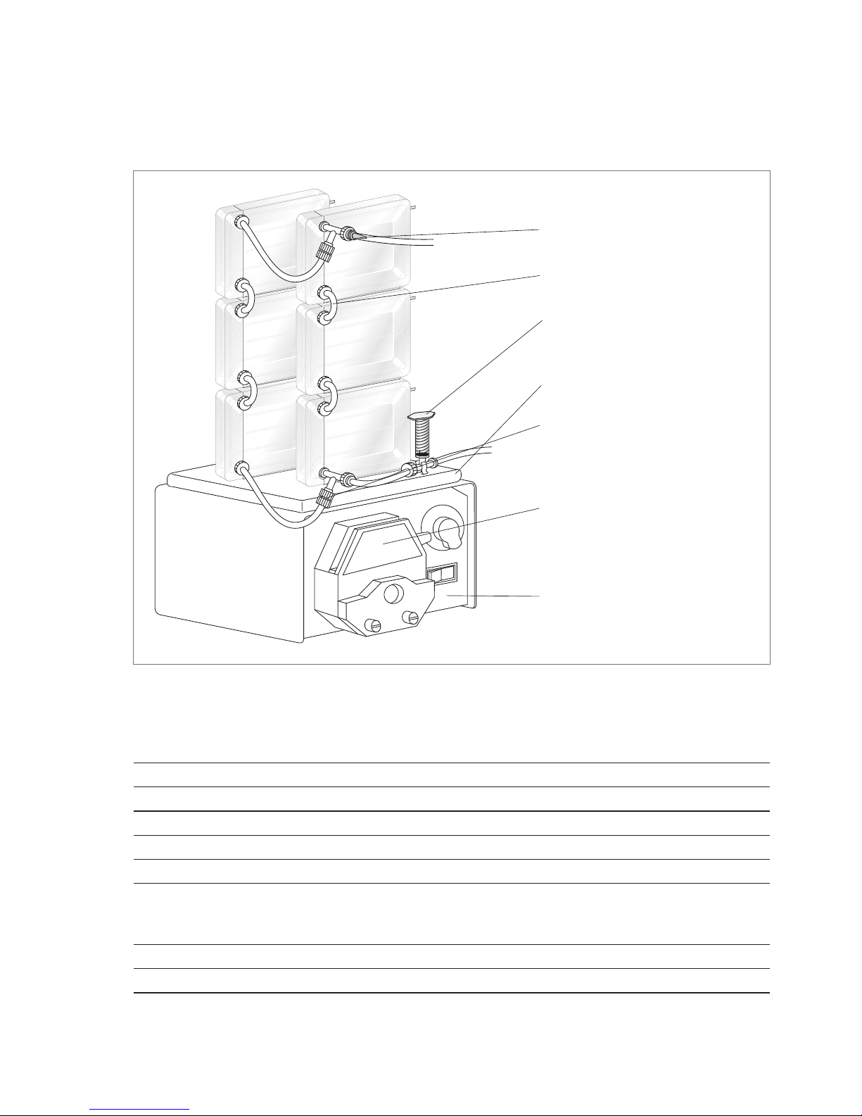
Table 1: Technical Specifications
Dimensions
Overall L|H|W 107|84|25 mm
Channel W|H 15 mm|0.3 mm
Active membrane area 50 cm
2
Hold up volume (module) 1.5 ml
Min recirculation volume < 10 ml
Non recoverable hold-up < 0.5 ml
Operating Conditions
Pump flow 200–400 ml/min
Maximum pressure 3 bar (45 psi)
Maximum temperature 60˚C
Inconnectors (Prod. No. VFA031)
Pink flow restrictor on
the return line
T-Connectors for running 2 stacks
(Prod. No. VFA030)
Pressure Indicator
(Prod. No. VFA020)
Masterflex easy load pump head
(Prod. No. VFA012)
Stand (Prod. No. VFA016)
Masterflex pump
CE 230V – US 115V
(Prod. No. VFP001|VFP002)
System Components
Diagram 4: System componets for setting up multiple Vivaflow 50 units
Page 8

Materials of Construction
Main housing Polycarbonate
Flow channel TPX (PMP)
Membrane support TPX (PMP)
Seals and O rings Silicone
Pressure indicator Polypropylene, SS Spring,
Flow restrictor Polypropylene
Fittings Nylon
Tubing PVC (medical grade)
Table 2: Performance characteristics
Time to concentrate up to 20x (min.) at 3 bar
inlet pressure, 20°C
Single Three Solute Recovery %
Device Devices
250 ml Start 1 L Start Direct 10 ml rinse
Vol. min. Vol. min.
BSA 1.0 mg/ml (66,000 MW)
5,000 MWCO PES 34 49 96% > 99%
10,000 MWCO PES 22 32 94% > 99%
30,000 MWCO PES 22 32 92% 99%
50,000 MWCO PES 20 29 92% 98%
γ Globulins 1.0 mg/ml
100,000 MWCO PES 43 62 92% 98%
100,000 MWCO RC 40 58 92% 98%
100,000 MWCO Hydrosart 40 58 92% 98%
Yeast 1.0 mg/ml (S.Cerevisiae)
0.2 µm PES 33 47 92% 98%
8 |
Page 9

| 9
Ordering Information
Vivaflow 50 include filtrate tube, size 16 peristaltic tubing, Pack Size Prod. No.
flow restrictor and fittings and 1 + Series Interconnector
3,000 MWCO (PES) 2 VF05P9
5,000 MWCO (PES) 2 VF05P1
10,000 MWCO (PES) 2 VF05P0
30,000 MWCO (PES) 2 VF05P2
50,000 MWCO (PES) 2 VF05P3
100,000 MWCO (PES) 2 VF05P4
0.2 µm (PES) 2 VF05P7
100,000 MWCO (RC) 2 VF05C4
Vivaflow 50 complete system comprises
Pump (240 V), easy load pump head (size 16), tubing, 1 VFS502
500 ml sample|diafiltration reservoir, module stand,
pressure indicator, T connectors, series interconnectors
Pump (115 V), easy load pump head (size 16), tubing, 1 VFS504
500 ml sample|diafiltration reservoir, module stand,
pressure indicator, T connectors, series interconnectors
Vivaflow 50 PVC tubing and fittings
Size 16 PVC pump tubing (3 metres, 3.2+ 1.6 mm) VFA004
Flow restrictor set (2+0.4, 0.6, 0.8 mm) VFA009
T connectors for running 2 stacks (2 pieces) VFA030
Series interconnectors (6 pieces) VFA031
Female luer fittings (10 pieces) VFA032
VF50 tubing kit (2+1 m size 16 PVC tubing with inlets fittings, VFA034
2+50 cm size 16 PVC tubing with 0.6 mm flow restrictors,
1+ series inlet connections)
Flow restrictor 0.6 mm (6 pieces) VFA035
Vivaflow 50 accessories
Masterflex economy drive variable speed peristaltic pump (230 V) VFP001
Masterflex economy drive variable speed peristaltic pump (115 V) VFP002
500 ml sample and|or diafiltration reservoir VFA006
Masterflex easy load pump head – size 15 VFA013
Masterflex easy load pump head – size 16 VFA012
Vivaflow 50 stand VFA016
Pressure indicator (1–3 bar) VFA020
Page 10

10 |
Table 3: Chemical Compatibility
for the Vivaflow 50
Solution PES RC
Acetic acid (25%) OK OK
Acetone NO NO
Ammonium hydroxide (5%) OK OK
Ammonium sulfate sat. OK OK
DMEM OK OK
Ethanol (70%) OK OK
Ethyl acetate NO NO
Formaldehyde (30%) OK OK
Formic acid (5%) OK OK
Guanidine HCl (6 M) OK OK
Hydrocarbons, Aromatic NO ?
Hydrocarbons, Chlorinated NO NO
Hydrochloric acid (1 M) OK NO
Isopropanol NO NO
Lactic acid (5%) OK OK
Mercaptoethanol (10 mM) OK OK
Methanol (60%) OK OK
n-Butanol (70%) OK OK
OK = Acceptable
? = Questionable
NO = Not recommended
Solution PES RC
Peracetic acid (0.2%) OK OK
Phenol (1%) OK ?
Phosphate Buffer (1 M) OK OK
Pyridine NO NO
RPMI-1640 OK OK
Sodium azide OK OK
Sodium deoxycholate (5%) OK OK
Sodium hydroxide (1 M) NO NO
Sodium hydroxide (0.1 M) NO NO
Sodium hypochlorite (0.02%) ? ?
Sodium nitrate NO NO
Sulfamic acid (5%) OK NO
Surfactants (0.1%) OK OK
Toluene NO NO
Trichloroacetic acid (10%) NO ?
Trifluoroacetic acid (10%) OK NO
Urea (8 M) OK OK
Page 11

Vivaflow 50R and Vivaflow 200
Operation Single Vivaflow 50R or
Vivaflow 200 Modules
Assembly and rinsing single module
1. Set up the system as illustrated above in
Diagram 5.. Note the positioning of the
flow restrictor on the return line. A set of
flow restrictors of different gauges (Product No. VFA009), is available for use with
solutions of unusually high or low viscosity.
!
Warning: Ensure Luer connections are
secure before operation.
2. Vivaflow membranes contain trace
amounts of glycerine and sodium azide.
To remove these chemicals and to check
the security of the tube connections, it is
recommended to rinse the module, and
to test the system at full pressure before
introducing the sample.
3. Place 500 ml deionised water in a
suitable reservoir.
4. Pump liquid through the system to purge
any air pockets. The recirculation rate
should be 200–400 ml/min, and suitable flow should exit the filtrate line. If
used, the pressure indicator should read
approximately 2.5 bar.
5. Allow 400 ml to pass into the filtrate
vessel. Check for any leakage at tubing
connection points.
6. Drain the system and empty or replace
the filtrate vessel (see Recovery section).
The system is now ready for use.
Diagram 5: Vivaflow 50R and Vivaflow 200 set up
| 11
Page 12
12 |
Operating two Vivaflow 50R or
two Vivaflow 200 Modules
Assembly and rinsing two modules
1. Set up the Vivaflow 50R system as illustrated in Diagram 6 and the Vivaflow 200
System as illustrated in Diagram 7 system as
illustrated above.
!
Warning: Ensure Luer connections are
secure before operation.
2. Vivaflow 50R:
Use two T-connectors (VFA030) to
connect to the inlets of both Vivaflow
50R modules.
Vivaflow 200:
Use the Y-connector, (VFA005)
to connect to the inlets of both
Vivaflow 200 modules.
The size 15 tubing connected to the
Y-connector is the inlet tubing for the
pump. Use a size 15 pump head.
Diagram 6: Setting up two Vivaflow 50R units
Page 13
| 13
3. Note the positioning of a flow restrictor
on the return line from each Vivaflow 200
module. Vivaflow membranes contain
trace amounts of glycerine and sodium
azide. To remove these chemicals and to
check the security of the tube connections,
it is recommended to rinse the module,
and to test the system at full pressure
before introducing the sample.
4. Place 1 litre of deionised water in a
suitable reservoir.
5. Pump liquid through the system to purge
any air pockets. The recirculation rate
should be 500–900 ml/min, and suitable flow should exit the filtrate line. If
used, the pressure indicator should read
approximately 2.5 bar.
6. Allow 800 ml to pass into the filtrate
vessel. Check for any leakage at tubing
connection points.
7. Drain the system and empty or replace
the filtrate vessel (see Recovery section).
The system is now ready for use.
Diagram 7: Setting up two Vivaflow 200 units
Page 14
Diafiltration|Desalting
1. Set up the system as illustrated in
Diagram 8.
2. Rinse the system as detailed previously.
3. Place the solution to be purified in a
suitable diafiltration reservoir. For volumes up to 500 ml the Vivaflow 500 ml
sample|diafiltration reservoir (VFA006),
is recommended. Ensure the lid is firmly
closed.
4. Fill the large feed reservoir with exchange
solvent and pump sample through the
system as for concentration.
5. As liquid passes through the membrane,
the vacuum created in the diafiltration reservoir draws in exchange solvent
through the feed line from the large reservoir. Over 99% solvent exchange
can be accomplished with an exchange
volume of approximately 5 times the
sample volume.
Concentration
1. Fill the feed reservoir with sample
solution.
2. Pump liquid through the system.
The recircu lation rate should be 200–
400 ml/min, (500–900 ml/min for two
modules), and suitable flow should exit
the filtrate line. If used, the pressure indicator should read approximately
2.5 bar.
!
Warning: Do not run the same section
of tubing through the pump-head for
longer than 6 hours, overuse of tubing
will result in significant pressure drop and
ultimately, failure.
3. Concentrate the sample.
4. When nearing the desired volume, reduce
the recirculation rate to 20–40 ml/min
and recirculate the concentrated sample for 1–2 minutes to increase sample
recovery.
Recovery
1. Remove the feed line from the sample.
2. Pump residual system volume back into
the reservoir|container.
3. For a more complete recovery, rinse
25–50 ml of water or sample buffer
through the system, and recover as
before.
14 |
Diagramm 8: Buffer exchange | Desalting with
Vivaflow 50R and Vivafow 200
Page 15

| 15
Table 4: Technical specifications Vivaflow 50R and Vivaflow 200
Dimensions Vivaflow 50 R Vivaflow 200
Overall L|H|W 100 | 100 | 24 mm 126|138|38 mm
Channel W|H 7.5 | 0.4 mm 10 mm|0.4 mm
Active membrane area 50 cm
2
200 cm
2
Hold up volume (module) 1.7 ml 5.3 ml
Min. recirculation volume 10 ml < 20 ml
Non recoverable hold-up < 0.5 ml < 1 ml
Materials of construction Vivaflow 50R and Vivaflow 200
Main housing Acrylic
Flow channel Acrylic
Membrane support Polypropylene
Seals and O rings Silicone
Pressure indicator Polypropylene, SS spring
Flow restrictor Polypropylene
Fittings Nylon
Tubing PVC (medical grade)
Operating conditions Vivaflow 50R and Vivaflow 200
Pump flow 200–400 ml/min
Maximum pressure 4 bar (60 psi)
Pressure drop across inlet | outlet 0.5 bar (7 psi)
Maximum temperature 60˚C
Page 16

Cleaning and storage information only for Vivaflow 50R
and Vivaflow 200
Cleaning
Vivaflow 50R and 200 modules may be
used several times if cleaning and storage
instructions are followed.
1. Flush the system with 200 ml of deionised water with the filtrate going
to waste.
2. Place the feed, return and filtrate lines
in a suitable container for the cleaning
solution.
3. Prepare cleaning solutions suitable for
the membrane.
I. Polyethersulfone membranes:
250 ml of 0.5 mM NaOCl in 0.5 M NaOH
II. Hydrosart membranes: 250 ml of
0.5 M NaOH
4. Recirculate at 50–100 ml/min for
30–40 minutes.
5. Drain the system and recirculate 250 ml
of deionised water through the system for
5–10 minutes.
6. Drain and discard rinse solution and
flush with a further 500 ml of deionised
water with the filtrate going to waste.
The system is now ready for further use.
Storage
To store Vivaflow 50R and Vivaflow 200
after cleaning, fill module with deionised
water and 10% ethanol. Seal inlet, outlet
and filtrate ports and refrigerate at
approximately 4°C.
16 |
Page 17

| 17
Table 5: Performance characteristics Vivaflow 50R
Time to concentrate up to 20x (min)
at 3.0 bar inlet | 2.5 bar outlet pressure, 20°C
start volume Average flux Recovery %
250 ml ml/min Direct 25 ml rinse
Lysozyme 0.25 mg/ml (14,000 MW)
5,000 MWCO Hydrosart 70 3.4 96% 98%
10,000 MWCO Hydrosart 23 10.3 94% 96%
BSA 1.0 mg/ml (66,000 MW)
10,000 MWCO Hydrosart 24 9.9 98% > 99%
30,000 MWCO Hydrosart 15 15.8 97% > 99%
γ Globulins 1.0 mg/ml (150,000 MW)
100,000 MWCO Hydrosart 46 5.2 97% > 99%
Start volume 1 litre (one Vivaflow 50R at 3 bar) 10,000 MWCO Hydrosart
BSA 1.0 mg/ml 95 10.0 98% > 99%
Start volume 1 litre (two Vivaflow 50R in parallel at 3 bar) 10,000 MWCO Hydrosart
BSA 1.0 mg/ml 48 19.8 98% > 99%
Page 18

18 |
Table 6: Performance characteristics Vivaflow 200
Time to concentrate up to 20x (min.) at 3 bar
inlet pressure, 20°C
start volume Average flux Recovery %
1 litre ml/min Direct 25 ml rinse
Lysozyme 0.25 mg/ml (14,000 MW)
2,000 MWCO Hydrosart 160 6 97% > 99%
3,000 MWCO PES 180 5 97% > 99%
BSA 1.0 mg/ml (66,000 MW)
5,000 MWCO PES 29 33 98% > 99%
5,000 MWCO Hydrosart 70 14 98% > 99%
10,000 MWCO PES 23 41 96% > 99%
10,000 MWCO Hydrosart 35 27 98% > 99%
30,000 MWCO PES 25 38 96% 99%
30,000 MWCO Hydrosart 20 48 96% > 99%
50,000 MWCO PES 22 43 96% 98%
γ Globulins 1.0 mg/ml (average 160,000 MW)
100,000 MWCO PES 54 18 96% 99%
Yeast 1.0 mg/ml (S. Cerevisiae)
0.2 µm PES 11 86 92% 98%
Dilute solute concentration, start volume 1 litre at 3 bar, 10,000 MWCO PES
BSA 0.001 mg/ml 18 52 90% 98%
BSA 0.01 mg/ml 20 47 92% 98%
BSA 0.1 mg/ml 21 45 94% 99%
Start volume 5 litres (two Vivaflow 200 in parallel at 3 bar) 10,000 MWCO PES
BSA 1.0 mg/ml (66,000 MW) 67 70 97% > 99%
Page 19

| 19
Ordering Information
Vivaflow 50R modules include pressure indicator, flow restrictor Qty per Prod. no.
and size 16 pvc peristaltic tubing and fittings box
5,000 MWCO Hydrosart 1 VF05H1
10,000 MWCO Hydrosart 1 VF05H0
30,000 MWCO Hydrosart 1 VF05H2
100,000 MWCO Hydrosart 1 VF05H4
Vivaflow 200 modules include pressure indicator, flow restrictor Qty per Prod. no.
and size 16 pvc peristaltic tubing and fittings box
3,000 MWCO PES 1 VF20P9
5,000 MWCO PES 1 VF20P1
10,000 MWCO PES 1 VF20P0
30,000 MWCO PES 1 VF20P2
50,000 MWCO PES 1 VF20P3
100,000 MWCO PES 1 VF20P4
0.2 µm PES 1 VF20P7
2,000 MWCO Hydrosart 1 VF20H9
10,000 MWCO Hydrosart 1 VF20H0
30,000 MWCO Hydrosart 1 VF20H2
100,000 MWCO Hydrosart 1 VF20H4
Vivaflow 50R | 200 complete system comprises
Pump (240 V), Easy load pump head (size 16), tubing, 1 VFS202
500 ml sample|diafiltration reservoir
Pump (115 V), Easy load pump head (size 16), tubing, 1 VFS204
500 ml sample|diafiltration reservoir
Page 20

20 |
Vivaflow 50R | 200 accessories
Masterflex economy drive variable speed peristaltic pump (230V) VFP001
Masterflex economy drive variable speed peristaltic pump (115V) VFP002
500 ml sample and|or diafiltration reservoir VFA006
Masterflex easy load pump head – size 16 VFA012
Masterflex easy load pump head – size 15 VFA013
(only for operating two Vivaflow 200)
Size 15 pvc pump tubing and Luer fittings (3 m, 4.8 + 2.6 mm) VFA003
Size 16 pvc pump tubing and Luer fittings (3 m, 3.2 + 1.6 mm) VFA004
Flow restrictor set (2 + 0.4, 0.6, 0.8 mm) VFA009
Female luer fittings size 16 (10 pieces) VFA032
Flow restrictors 0.6 mm (6 pieces) VFA035
Female luer fittings size 15 (10 pieces) VFA036
Flow restrictor set (2 + 0.4, 0.6, 0.8 mm) VFA009
Female luer fittings size 16 (10 pieces) VFA032
Flow restrictors 0.6 mm (6 pieces) VFA035
Female luer fittings size 15 (10 pieces) VFA036
Vivaflow 200 tubing and fittings for operation two modules
Y connector (size 15 to 2 + size 16, Luer fittings) VFA005
Masterflex easy load pump head – size 15 VFA013
Vivaflow 50R tubing a fittings for operation of two modules
T-Connector VFA030
Page 21

| 21
Solution PES HY
Peracetic acid (0.2%) OK NO
Phenol (1%) OK NO
Phosphate Buffer (1 M) OK OK
Pyridine NO NO
RPMI-1640 OK OK
Sodium azide OK OK
Sodium deoxycholate (5%) OK ?
Sodium hydroxide (1 M) OK OK
Sodium hydroxide (0.1 M) OK OK
Sodium hypochlorite (0.02%) OK NO
Sodium nitrate NO OK
Sulfamic acid (5%) OK ?
Surfactants (0.1%) OK OK
Toluene NO NO
Trichloroacetic acid (10%) NO OK
Trifluoroacetic acid (10%) OK OK
Urea (8 M) OK OK
Table 7: Chemical Compatibility
for Vivaflow 50R and Vivaflow 200
Solution PES HY
Acetic acid (25%) OK OK
Acetone NO NO
Ammonium hydroxide (5%) OK OK
Ammonium sulfate sat. OK ?
DMEM OK OK
Ethanol (70%) OK OK
Ethyl acetate NO NO
Formaldehyde (30%) OK OK
Formic acid (5%) OK OK
Guanidine HCl (6 M) OK OK
Hydrocarbons, Aromatic NO NO
Hydrocarbons, Chlorinated NO NO
Hydrochloric acid (1 M) OK OK
Isopropanol NO NO
Lactic acid (5%) OK OK
Mercaptoethanol (10 mM) OK OK
Methanol (60%) OK OK
n-Butanol (70%) OK OK
OK = Acceptable
? = Questionable
NO = Not recommended
Page 22

22 |
Page 23

| 23
Page 24

Sartorius Stedim Lab Ltd
Sperry Way
Stonehouse Park
Gloucestershire
GL10 3UT, UK
www.sartorius.com
Copyright by
Sartorius Lab Instruments
GmbH & Co. KG, Goettingen,
Germany.
All rights reserved. No part
of this publication may
be reprinted or translated in
any form or by any means
without the prior written
permission of Sartorius Lab
Instruments GmbH & Co. KG.
The status of the information,
specifications and illustrations
in this manual is indicated
by the date given below.
Sartorius Lab Instruments
GmbH & Co. KG reserves the right
to make changes to the technology,
features, specifications and design
of the equipment without notice.
Status:
June 2016,
Sartorius Lab Instruments
GmbH & Co. KG,
Goettingen, Germany
Printed in the EU on paper bleached
without chlorine.
Publication No.: SLU6097-e160609
Ver. 06 |2016
 Loading...