

Page 1
Installation Instructions | Installationsanleitung | Notice d’installation |
Instrucciones de instalación | Installationsanvisning
PMA.Vision
VIS1X
Paint-mixing Scales for Potentially Explosive Areas Zone 1 |
Farbmischwaagen für den Einsatz in explosionsgefährdeten Bereichen der Zone 1 |
Balances pour peintures pour atmosphères explosibles de la zone 1 |
Balanzas para la mezcla de pinturas en áreas potencialmente explosivas de la zona 1 |
Färgblandningsvågar för insats i explosionsfarliga områden i zon 1
98648-020-36
Page 2

English – page 3
In cases involving questions of interpretation,
the German-language version shall prevail.
Deutsch – Seite 17
Im Auslegungsfall ist die deutsche Sprache maßgeblich.
Français – page 31
En cas de questions concernant l‘interprétation,
la version en langue allemande fera autorité.
Español – página 45
En caso de interpretación, la versión en lengua
alemana será determinante.
Svenska – sidan 59
I oklara fall är den tyska tolkningen avgörande.
Page 3
English
Contents
1 About this Document . . . . . . . . . . . . . . . . . . . . . . . . . . . . . . . . . . . . . 3
1.1 Scope.................................................. 3
1.2 Symbols Used .........................................3
2 Safety Precautions
2.1 Intended Use..........................................4
2.2 Explosion Protection..................................4
2.3 Personnel Qualification...............................4
2.4 Significance of these Instructions ....................5
2.5 Proper Working Order of the Device .................5
2.6 Work on the Electrical Equipment of the Device.....5
2.7 Personal Protective Equipment....................... 5
2.8 Safety Instructions Concerning Operation
of the Device.......................................... 5
3 Installation
3.1 Scope of Delivery .....................................6
3.2 Unpacking the Device.................................6
3.3 Selecting a Setup Location ...........................6
3.4 Installing the Scale....................................6
3.5 Connecting the Grounding Cable.....................7
3.6 Establishing the Power Supply........................7
3.7 Anti-Theft Locking Device ............................8
3.8 Warm-up Time........................................8
4 Accessing the Scale via the Network
4.1 Connecting to a Network with DHCP.................8
4.2 Connecting to a Network with a Fixed IP Address ...9
4.3 Testing the Network Connection ....................10
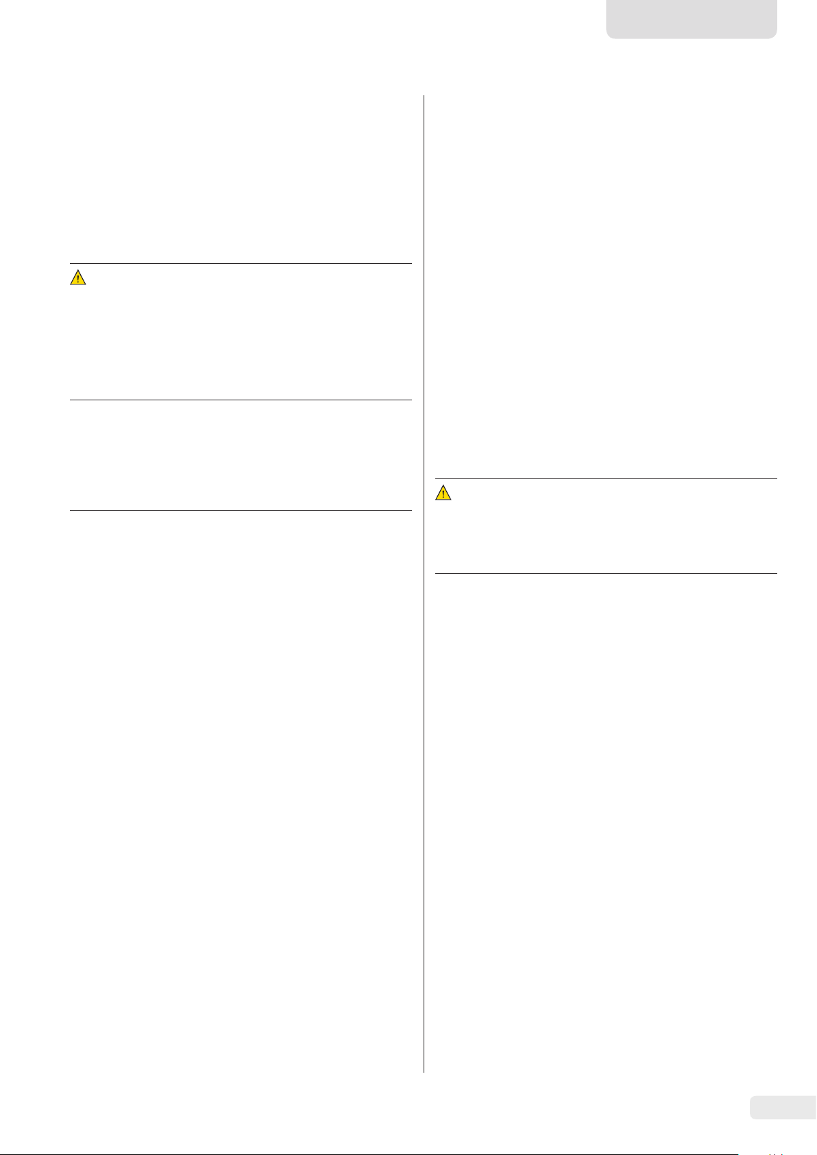
4.4 Overview of the Connection States..................12
5 Cleaning and Maintenance
5.1 Cleaning..............................................13
5.2 Servicing .............................................13
6 Disposal
6.1 Information on Decontamination ...................13
7 Accessories
8 Serial Number Coding
9 Technical Data
9.1 General Data.........................................15
9.2 Model-Specific Data.................................16
9.3 Verified Models with EU Type Examination
................................................6
. . . . . . . . . . . . . . . . . . . . . . . . . . . . . . . . . . . . . . . . . . . . . . . . . . . 13
................................................14
Certificate: Model-Specific Specifications...........16
........................................4
....................8
..............................13
...................................14
............................................15
1 About this Document
1.1 Scope
These instructions apply to color-mixing scale models:
− VIS1X
− VIS1X...EU
1.2 Symbols Used
The term “device” used in these instructions always refers to
the combined unit of scale, power supply, and ex-link
converter.
1.2.1 Warnings
WARNING
Denotes a danger with risk that death or severe injury may
result if it is not avoided.
CAUTION
Denotes a danger with risk that moderate or minor injury may
result if it is not avoided.
NOTICE
Denotes a danger with risk that property damage may result if
the risk is not avoided.
1.2.2 Other Symbols
t
y
[ ] Text inside brackets refers to control and display
Required action: Describes actions which must be
carried out.
Result: Describes the result of the actions carried
out.
elements.
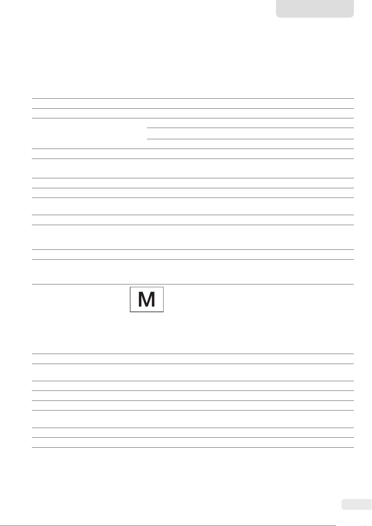
This symbol provides information for the sale of
scales verified for use in legal metrology.
In the following, the term “verified” is used to
mean “verified for use in legal metrology” or
“conformity-assessed.”
10 EU Declaration of Conformity
..........................16
Figures on the Operating Display
The figures in these instructions are based on “standard”
scales. On verified scales, some displays and reports may
deviate slightly from the figures. Where this is significant
for operation, the differences will be explained in the text.
Installation Instructions VIS1X 3
Page 4

2 Safety Precautions
2.1 Intended Use
This scale is used for mixing colors and paints. The scale is
always connected to the ex-link converter YCO16-Z installed
outside of the potentially explosive area at all times using
only the link cable supplied. The scale can be used in
potentially explosive areas in Zone 1. Appropriate containers
must be used for loading each type of material.
The scale is controlled via the operating display. Formulas can
be written into the scale using a web application via a tablet,
smartphone, or PC. The PC is connected to the ex-link
converter installed outside of the potentially explosive area
either via a network or directly via an Ethernet cable.
The device may only be used indoors.
2.2 Explosion Protection
If the device is used outside the Federal Republic of Germany,
the relevant national electrical codes and safety regulations
must be observed. Ask your dealer or Sartorius Service about
the guidelines that apply in their country.
Use within the Scope of Validity of the European ATEX
Directive:
− In accordance with Directive 2014/34/EU, the model in the
VIS1X series is a Category 2 device, suitable for use in Zone
1 potentially explosive areas.
− The ex-link converter YCO16-Z is an associated electrical
apparatus that can only be installed outside of the
potentially explosive area.
− Refer to the EU type examination certificates from
page 73 for the device ID codes. Please observe the
safety instructions in drawing 2003810 from page 73.
Only use the device with the equipment and under the
operating conditions described in the Technical Data.
Do not modify the device or make any technical changes.
These instructions are part of the device. The device is
intended exclusively for use in accordance with these
instructions.
Any further use beyond this is considered improper. If the
device is not used properly: The protective systems of the
device may be impaired. This can lead to personal injury and
property damage.
In the event of use in systems and ambient conditions which
have greater safety requirements, you must observe the
requirements and provisions applicable in your country.
Operating Conditions for the Device
The device may only be used indoors.
The device may only be used with the equipment and under
the operating conditions described in the Technical Data
section of these instructions.
You may not modify the device or make any technical
changes on your own. Any retrofitting or technical changes to
the device are only permitted with prior written permission
from Sartorius.
Do not expose the device or accessories supplied by Sartorius
to extreme temperatures, aggressive chemical vapors,
moisture, shock, vibrations, or strong electromagnetic fields.
Observe the operating conditions described in the Technical
Data section.
The casing on all connection cables between the devices as
well as on the wires inside the device housing is made of PVC.
Chemicals that corrode this material must be kept away from
these cables.
Use in Canada and the USA:
− The intrinsically safe scales in the VIS1X model series are
suitable for use in Class I, Division 1 and Class I, Zone 1.
− The ex-link converter YCO16-Z is an associated electrical
apparatus that can only be installed outside of the
potentially explosive area.
− Please observe Certificates of Compliance 3055566 as well
as Control Drawing 2003809 from page 73.
Use in Australia/New Zealand:
Please observe IECEx Certificate of Conformity IECEx FME
15.0007X and Safety Instructions 2003810 from page 73.
2.3 Personnel Qualification
These instructions are addressed to the target groups
mentioned below. All persons working on the device must
possess the stated knowledge and authorizations.
If no qualifications are indicated for the actions described in
these instructions: The actions described are addressed to the
“User” target group.
If individual actions must be carried out by other target
groups or by Sartorius Service personnel: The qualification
required will be indicated in the description of the action.
4 Installation Instructions VIS1X
Page 5
English
Target group Knowledge/authorizations
User The user is familiar with the operation of the
device and the associated work processes. They
understand the hazards which may arise when
working with the device and can avoid these
hazards.
The user has been trained in the operation of
the device. Training takes place during startup
and is carried out by the operating engineer/
laboratory manager or the operator of the
device.
Operating
engineer/
laboratory
manager
Electrician A qualified electrician has the specialized
Operator The operator of the device is responsible for
The operating engineer/laboratory manager
makes decisions about the use and configuration of the device.
The operating engineer/laboratory manager is
trained in the operation of the device. Training
takes place during startup and is carried out
by Sartorius Service or the operator.
training, knowledge, and experience as well
as familiarity with applicable regulations to
evaluate the assigned work and identify
possible hazards.
compliance with safety requirements and
workplace safety regulations.
The operator must ensure that anyone working with the device has access to the relevant
information and has been trained to work
with the device.
2.4 Significance of these Instructions
Failure to follow the instructions in this manual can have
serious consequences, e.g. exposure of individuals to electrical,
mechanical, or chemical hazards.
t Before working with the device: Read the instructions
carefully and completely.
t If these instructions are lost: Request a replacement or
download the latest version from the Sartorius website
(www.sartorius.com).
t The information contained in these instructions must be
available to all individuals working on the device.
2.5 Proper Working Order of the Device
2.6 Work on the Electrical Equipment of the Device
Work on and modifications to the electrical equipment of the
device may only be carried out by Sartorius Service personnel.
The device may only be opened by Sartorius Service personnel.
Seal on scales verified for use in legal metrology
Legislation requires that a seal be affixed to
verified scales. On Sartorius devices, this seal takes
the form of a sticker with the “Sartorius” logo.
If the seal is removed, the validity of verification
will become void and you must have your scale
re-verified. For verified scales for use in the EEA,
the declaration of conformity set out in the
calibration and supplied here shall apply. Please
keep it in a safe place.
2.7 Personal Protective Equipment
Personal protective equipment protects against risks arising
from the material being processed.
t When the workplace or the process in which the device
is used requires personal protective equipment: Wear
personal protective equipment.
2.8 Safety Instructions Concerning Operation of the Device
− Take care that the glass panel of the operating display is
not damaged (e.g., by falling objects, impact, or extreme
pressure). If the glass panel is damaged, disconnect the
device from the power supply immediately.
− The surface of the operating display should not be touched
with pointed, sharp, hard, or rough objects. You should
only use the touch pen provided or your fingertips. Do not
use parts of clothing (e.g., sleeves) or sponges for cleaning
because these can scratch the surface (e.g., due to rivets or
buttons in the sleeve or sand in the sponge).
− Avoid generating static electricity on the glass panel of
the operating display and plastic casing.
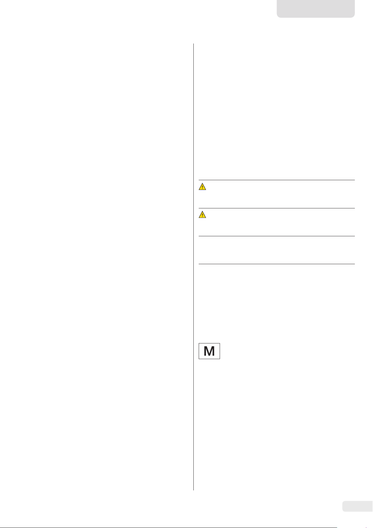
Danger of damage to the scale!
Never close a paint can using a hammer while
it is still on the weighing pan.
When closing, place the paint can on a firm,
stable surface.
A damaged device can cause malfunctions or lead to hard-todetect hazards.
t Only operate the device when it is safe and in perfect
working order.
t Immediately disconnect the damaged device from the
power.
t Have any malfunctions or damage repaired immediately by
Sartorius Service personnel.
Installation Instructions VIS1X 5
Page 6

3 Installation
3.1 Scope of Delivery
3.4 Installing the Scale
NOTICE
The device must be disconnected from the power supply for
all assembly work.
Item Quantity
Large weighing pan: d 233 mm
USB cable, 3 m 1
Power supply YPS07-USB 1
Ex-link converter 1
Link cable from converter to scale 1
Installation instructions 1
1
3.2 Unpacking the Device
Procedure
t Open the packaging, making sure to remove all parts
carefully.
t After unpacking the device, check it immediately for any
external damage.
t If the device is stored temporarily: Store the device
according to the ambient conditions (for ambient
conditions, see Chapter “9.1 General Data,” page 15).
t Save all parts of the original packaging for any future
transport. All cables should be unplugged when
transporting.
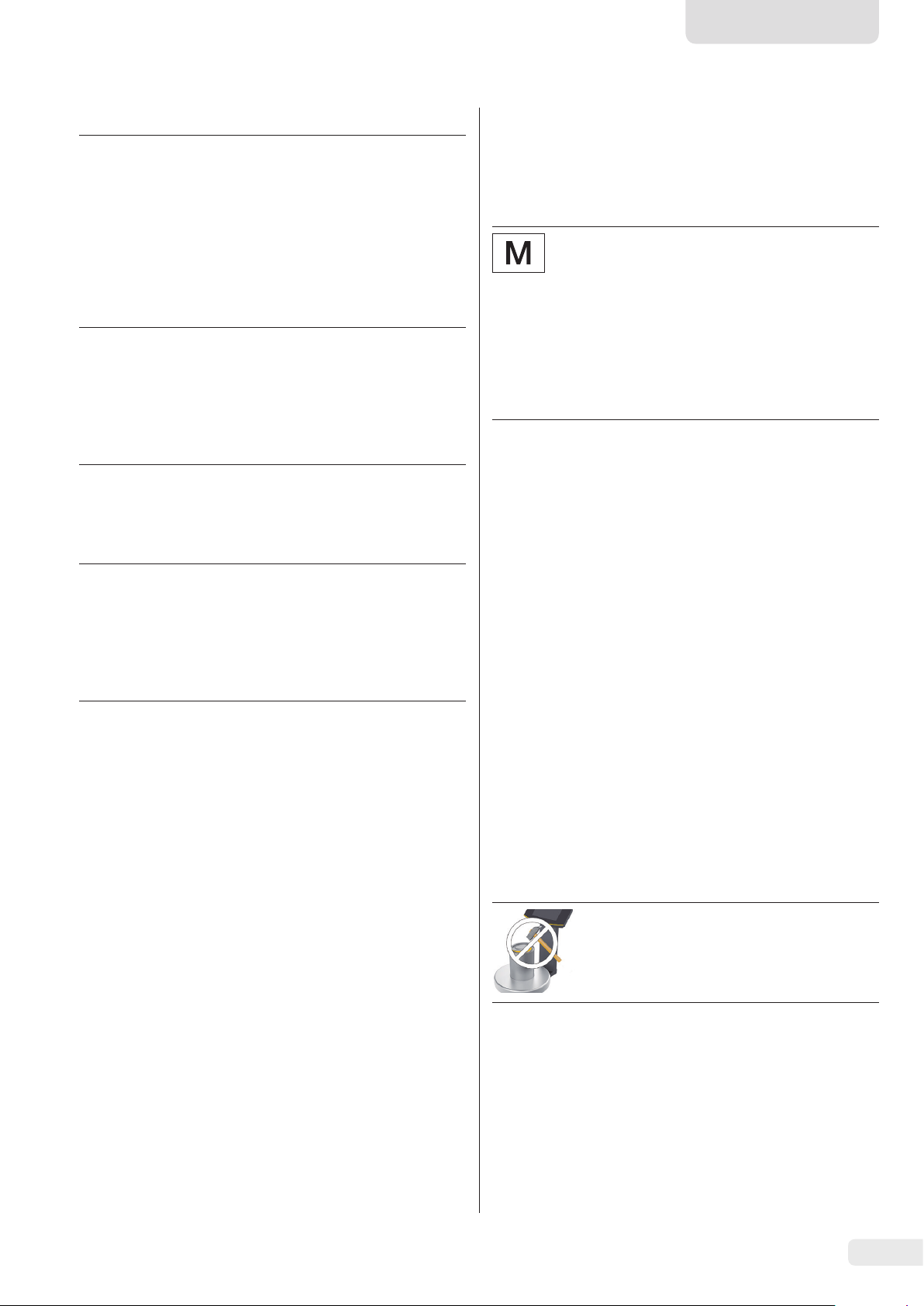
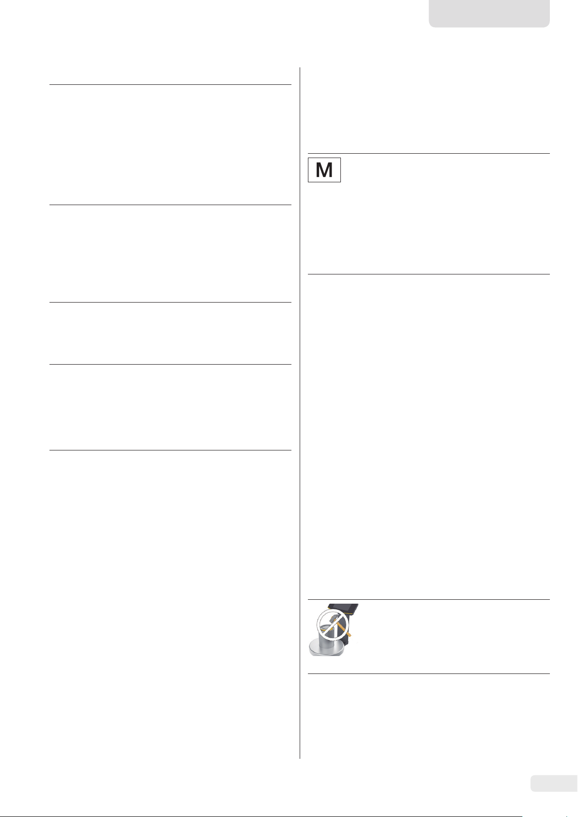
t Place the weighing pan onto the
scale from above.
3.4.1 Connecting the Scale
t Insert the link cable plug into
the socket on the back of the
display.
t Lay the link cable through the
cable holders on the back of the
scale.
3.3 Selecting a Setup Location
Select the right setup location:
− Set up the device on a stable, even surface that is not
exposed to vibrations.
− Maintain free access to the device at all times.
Choose a location that is not subject to the following negative
influences:
− Heat (heater or direct sunlight)
− Drafts from open windows, AC systems, and doors
− Extreme vibrations during weighing
− Heavy “traffic areas” (personnel)
− Extremely high humidity
− Electromagnetic fields
− Extremely dry air
Acclimatization
Condensation from humidity can form on the surfaces of a
cold device when it is brought into a warm area. You should
therefore let a device that has been disconnected from its
power source acclimatize for approximately 2 hours before
reconnecting it to the supply voltage.
t Connect the link cable to the
ex-link converter.
Connecting a PC/Notebook
t Plug an Ethernet cable (1)
into the ex-link converter
and connect the cable
to a Windows PC (direct
1
connection) or to the
network.
6 Installation Instructions VIS1X
Page 7
English
3.5 Connecting the Grounding Cable
Required qualification: Electrician
This explosion-protected system should be set up according
to commonly accepted technical standards. The applicable
national electrical codes and safety regulations for your
particular country must be observed.
Before starting up the scale, a check must be carried out by or
under the supervision of a qualified electrician to ensure that
the system is in good working order.
Check whether or not the competent authorities (e.g.,
industrial supervisory board) need to be informed. It is also
necessary to carry out inspections of the system during
operation.
Inspection intervals should be such that any significant
defects that may occur can be identified in good time.
Inspections should be carried out at least once every three
years. The applicable requirements and guidelines should also
be observed during operation.
The system should only be operated for the first time when
it is certain that the area is not potentially explosive.
If deviations are evident during startup due to transport
damage (e.g., no display, no backlighting), disconnect the
scale from the power supply and contact Sartorius Service.
Installation must be carried out properly by a trained
electrician and according to commonly accepted technical
standards.
Connect the scale to the equipotential bonding conductor using
an equipotential bonding cable
with a gage of at least 4 mm².
3.6 Establishing the Power Supply
Required qualification: Electrician
The scale is connected to the power source using the power
supply YPS07-USB (see Chapter “7 Accessories,” page 14),
which is supplied with mains adapters for use in various
countries.
NOTICE
− Ensure that the voltage rating printed on the power supply
is identical to your local supply voltage (for connection
data, see Chapter “9.1 General Data,” page 15).
− If the stated supply voltage or the plug design of the
power supply does not comply with your country’s
standard, please inform your nearest Sartorius
representative.
Power supply assembly is described in the following.
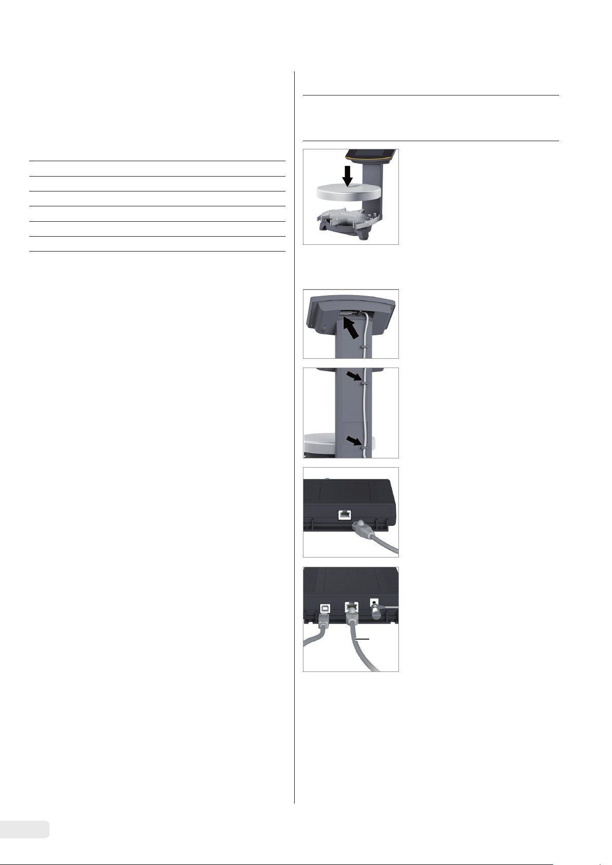
3.6.1 Installing the Power Supply
WARNING
t
Lethal electric shock and equipment damage due to
incorrect power plug adapter! Only use the countryspecific power plug adapter. Never plug the power plug
adapter into the socket when it is disconnected from the
power supply.
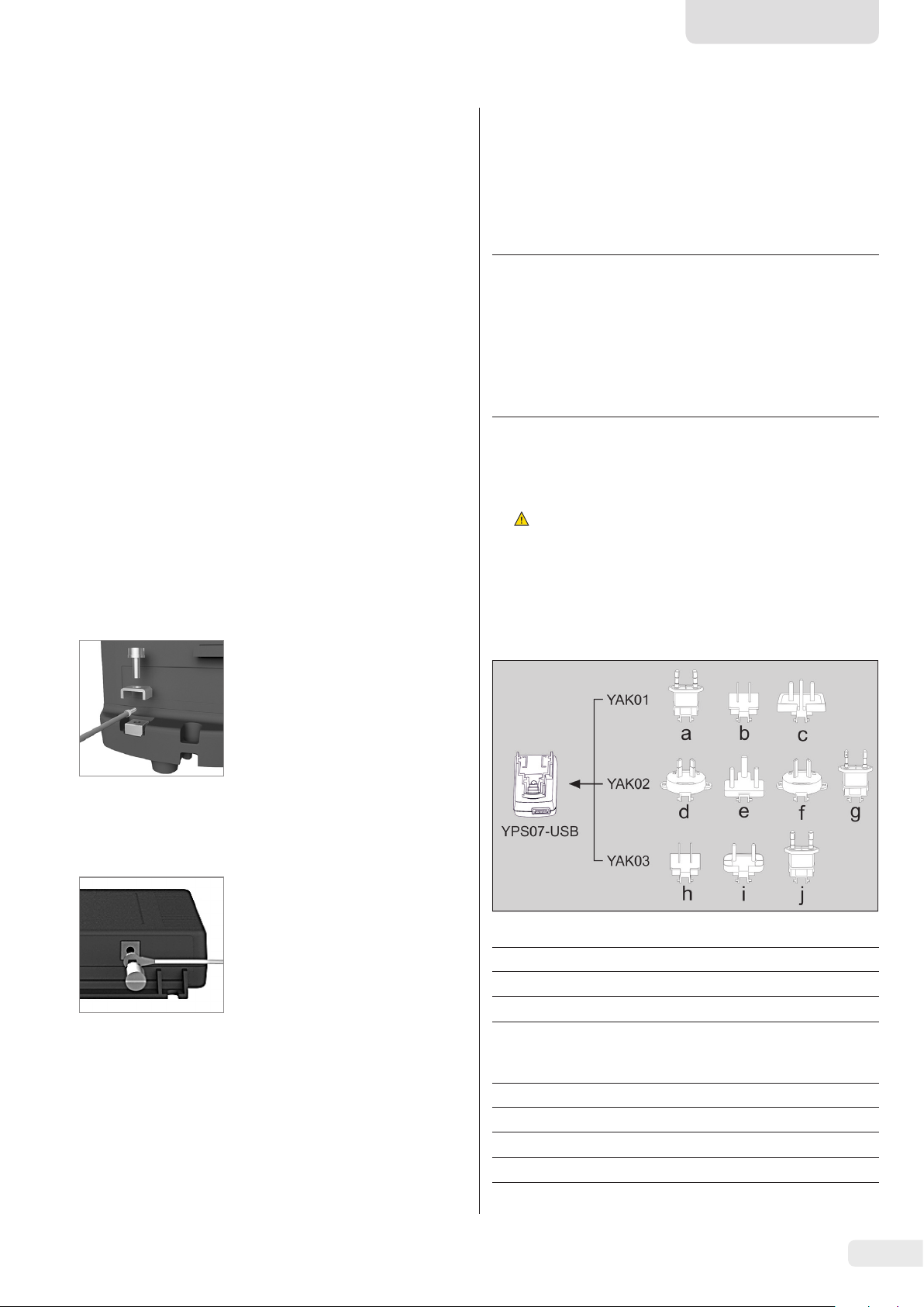
t Use the right mains adapter for your mains power supply:
t Connect the cable lug of the
equipotential bonding cable to
the grounding terminal of the
scale.
t Connect the equipotential
bonding cable to the customersupplied equipotential bonding
conductor.
Connect the ex-link converter to
the equipotential bonding conductor using another equipotential
bonding cable with a gage of at
least 4 mm².
t Connect the cable lug of the
equipotential bonding cable to
the grounding terminal of the
ex-link converter.
t Connect the equipotential
bonding cable to the customersupplied equipotential bonding
conductor.
Mains adapter set YAK01
Bag Region/country
a) transparent Europe/EU (except United Kingdom)
b) blue USA
c) yellow United Kingdom
Mains adapter set YAK02
Bag Region/country
d) red Australia
e) turquoise South Africa
f) white Argentina
g) pink Brazil
Installation Instructions VIS1X 7
Page 8
Mains adapter set YAK03
0
30
3.7 Anti-Theft Locking Device
Bag Region/country
h) light brown China
i) black India
j) green Korea
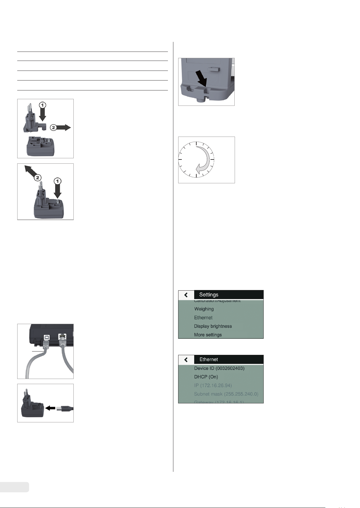
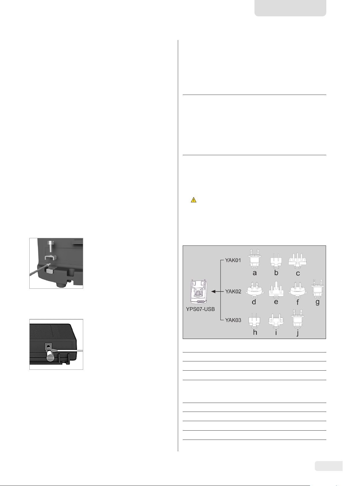
t Push (1) and slide (2) the mains
adapter required for your power
source into the opening of the
power supply module.
When doing this, the mains
adapter needs to lock into
position.
Removing/Replacing the
Mains Adapter
t Unlock (1) and then remove (2)
the mains adapter.
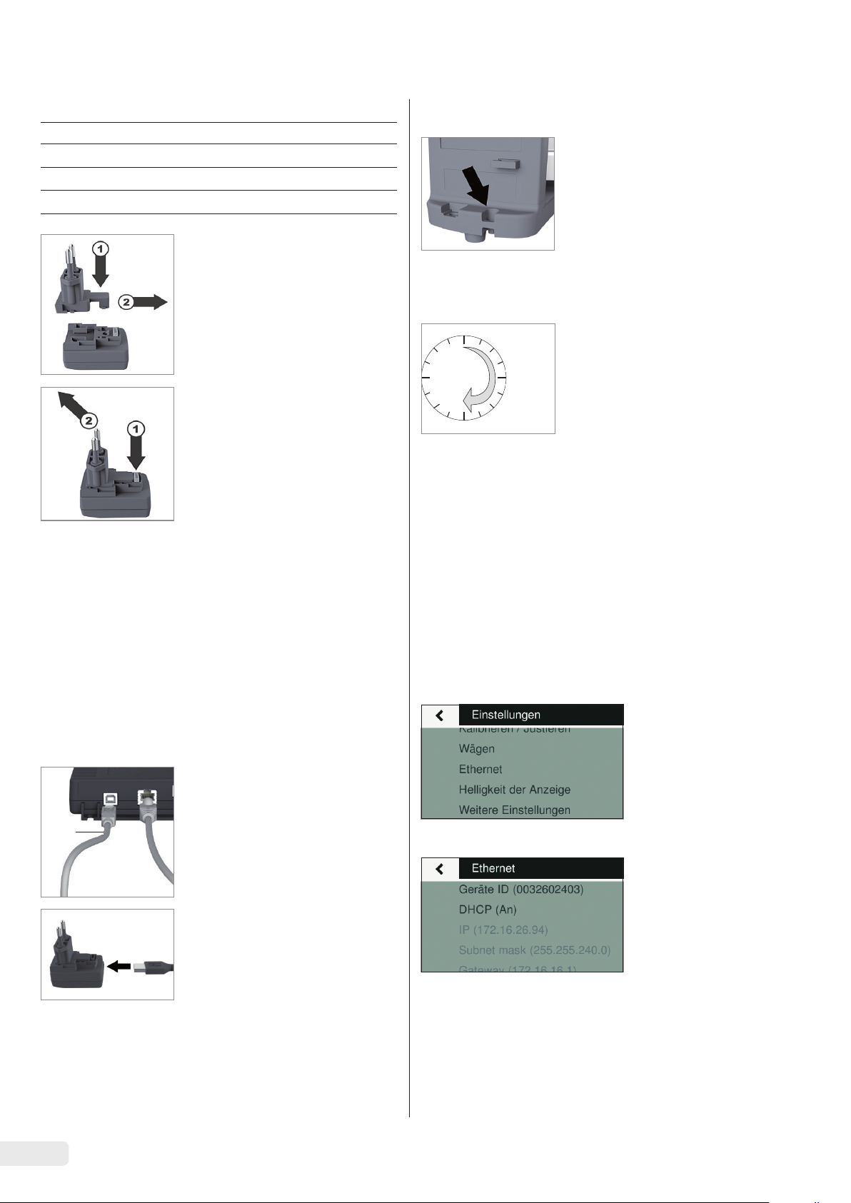
t If required, secure the scale at
the back.
3.8 Warm-up Time
To ensure accurate results are
delivered, the scale must warm up
for at least 30 minutes after initial
connection to the power supply.
Only then will the device have
reached the required operating
temperature.
4 Accessing the Scale via
the Network
Power Connection/Safety Precautions
− Only use original Sartorius power supplies.
The power supply has an IP rating of IP40 in accordance
with EN60529/IEC60529.
− Make sure that the voltage rating printed on this unit
matches the voltage at the place of installation.
− If the stated supply voltage or the plug design of the
power supply does not comply with your country’s
standard, please inform your nearest Sartorius
representative.
− The power must be connected in accordance with the
regulations applicable in your country.
Connection to the Power Supply
t Insert a USB cable (2) into the
ex-link converter.
2
t Insert the USB cable into the
YPS07-USB power supply.
t Plug the power supply into a
wall outlet (supply voltage).
4.1 Connecting to a Network with DHCP
Usually, the IP address on a network is assigned by a DHCP
server (Dynamic Host Configuration Protocol). A prerequisite
for this is that DHCP mode is enabled on the scale.
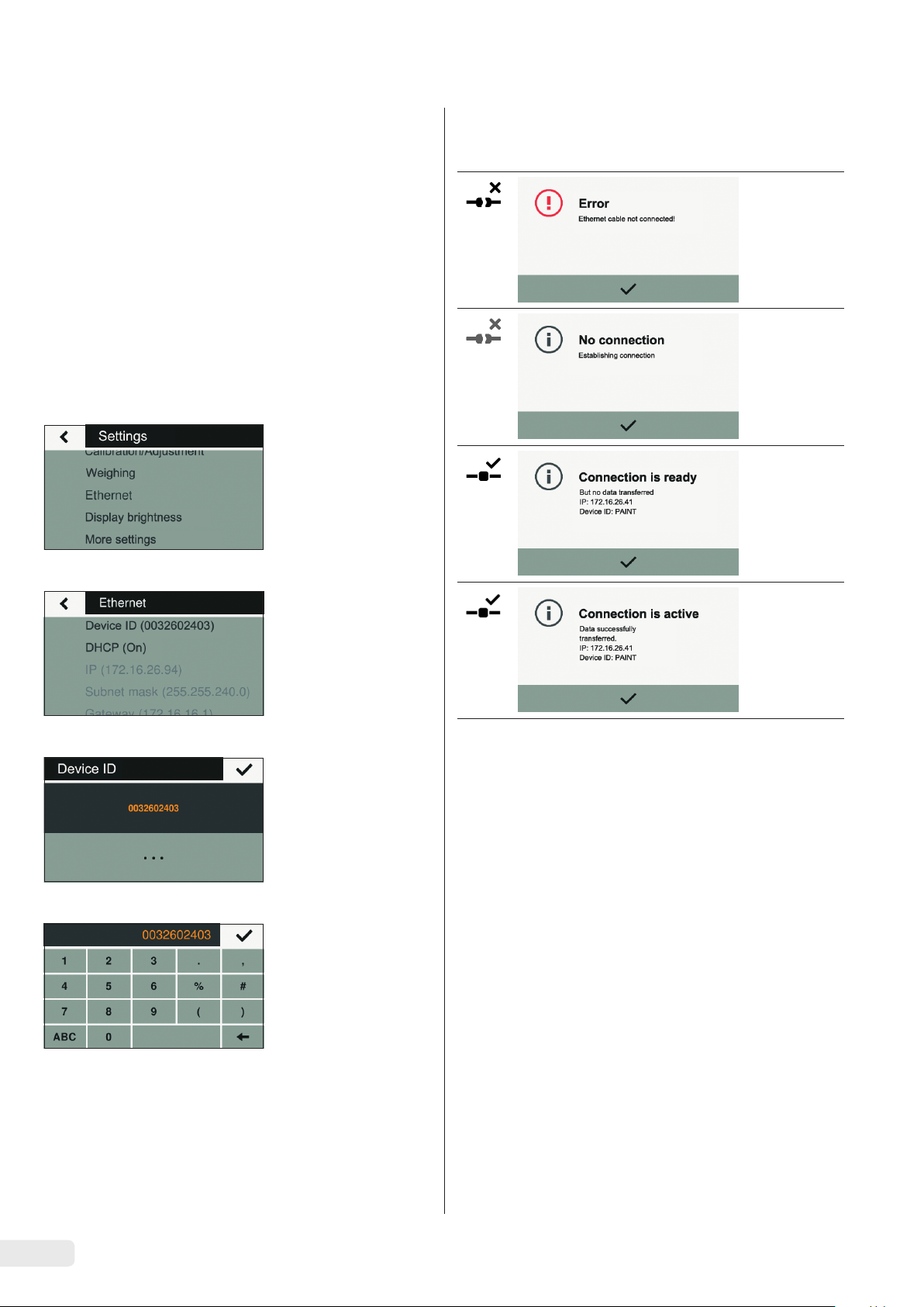
t Press the i button to call up the “Settings” menu.
t Go into the submenu “Ethernet.”
If the display says “DHCP (On),” the settings are correct.
8 Installation Instructions VIS1X
Page 9
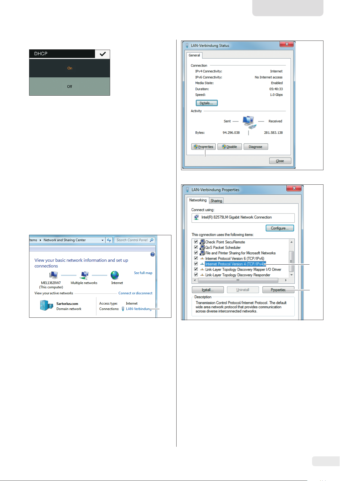
t If not, go into the submenu “DHCP.”
t Select “On.”
t Confirm with the l button.
y The DHCP mode is now enabled.
When you switch on the scale, the scale is automatically
assigned an IP address by the DHCP server.
t Check the network connection (see Chapter 4.3,
page 10).
English
4.2 Connecting to a Network with a Fixed IP Address
The following settings must be made to connect the scale to
a network with fixed IP addresses:
4.2.1 Configuring a Network on a PC
t Open the Network and Sharing Center on your Windows
PC:
Start -> Control Panel -> Network and Sharing Center
1
t Open the LAN connection (1).
2
t Call up the properties (2) of the LAN connection.
3
4
t Select the entry “Internet Protocol Version 4“ (3) from the
list.
t Open the properties (4).
Installation Instructions VIS1X 9
Page 10
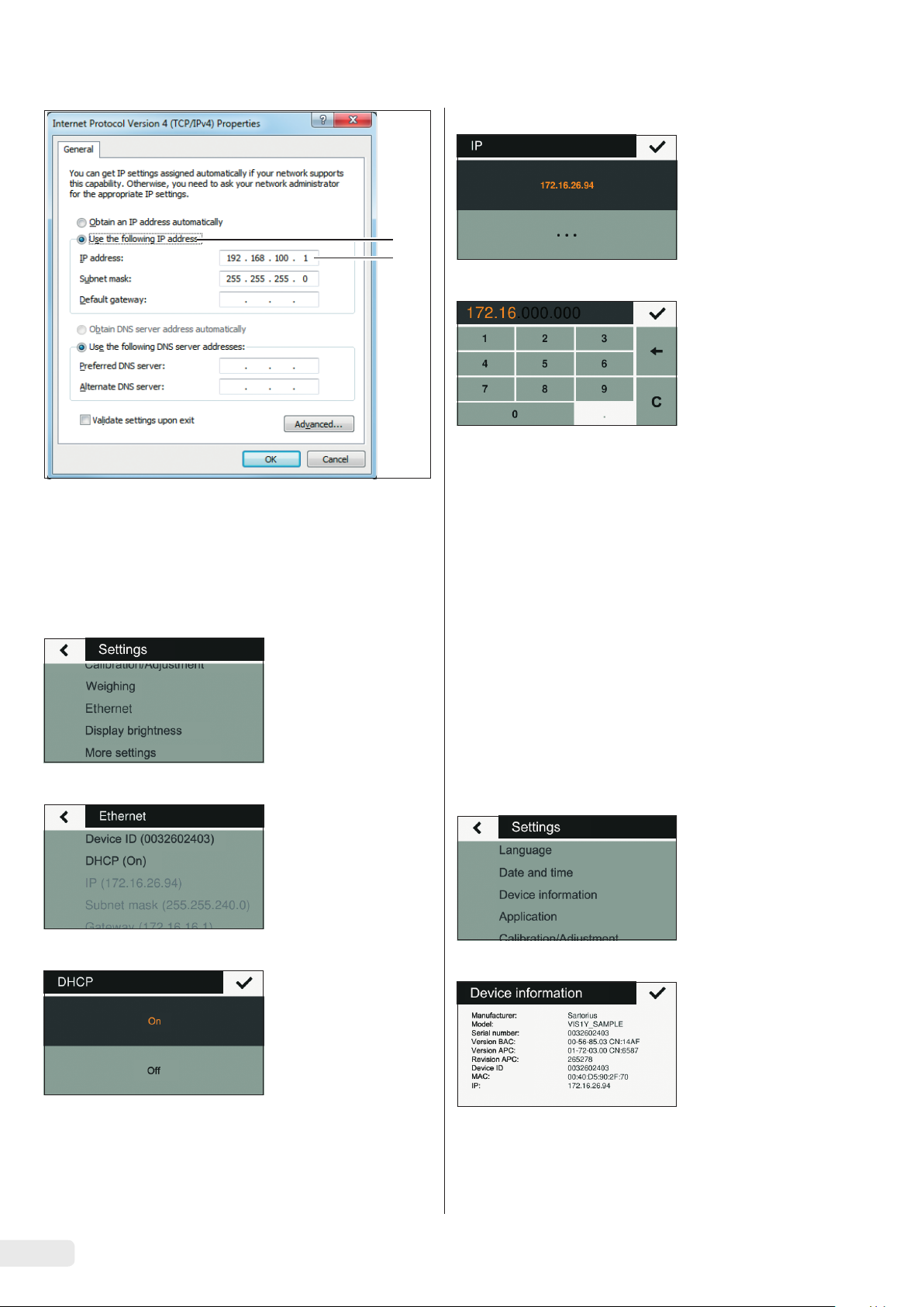
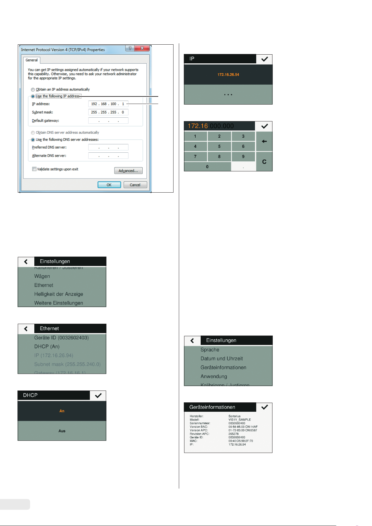
t Select “Use the following IP address” (5).
t Enter the IP address of the network connection (6).
t Confirm your entry with “OK” and close each of the
following windows with “OK.”
4.2.2 Configuring a Network on the Scale
t Press the i button to call up the “Settings” menu.
t Go into the submenu “IP (xxxxxxx).”
5
6
t Select “t” to enter a new IP address.
t Enter a new IP address using the input box.
Make sure:
− to use an IP address from the same address space as
the Windows PC (Subnet mask).
− not to use the same IP address as the Windows PC.
t Confirm the entry with the l button and exit the Settings
menu.
The settings may also have to be configured in the submenu
“Subnet mask” and “Gateway.”
t Restart the scale.
t Check the network connection (see Chapter 4.3,
page 10).
t Go into the submenu “Ethernet.”
t Go into the submenu “DHCP.”
t Select “Off.”
t Confirm with the l button.
y The DHCP mode is turned off.
4.3 Testing the Network Connection
The IP address and device ID can always be found in the
submenu “Device Information.”
t Press the i button to call up the “Settings” menu.
t Go into the submenu “Device information.”
10 Installation Instructions VIS1X
Page 11
English
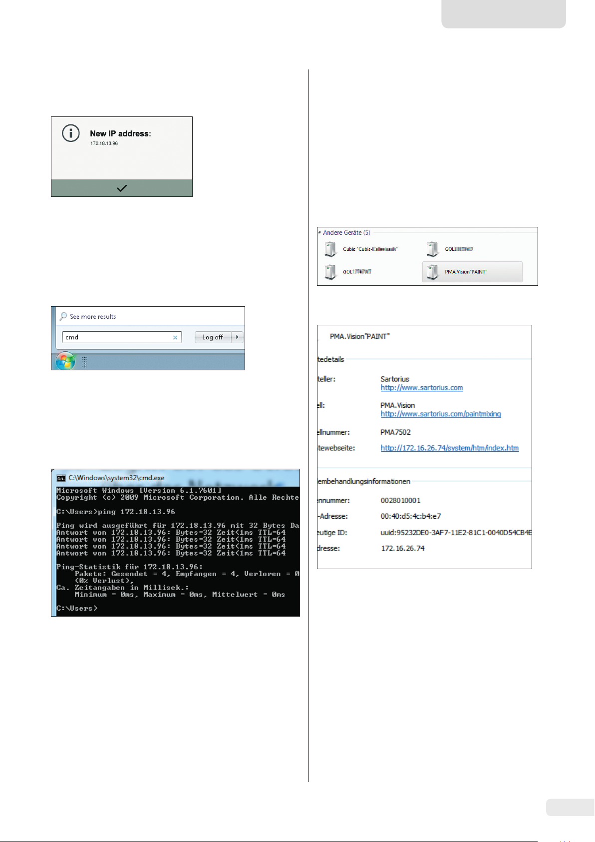
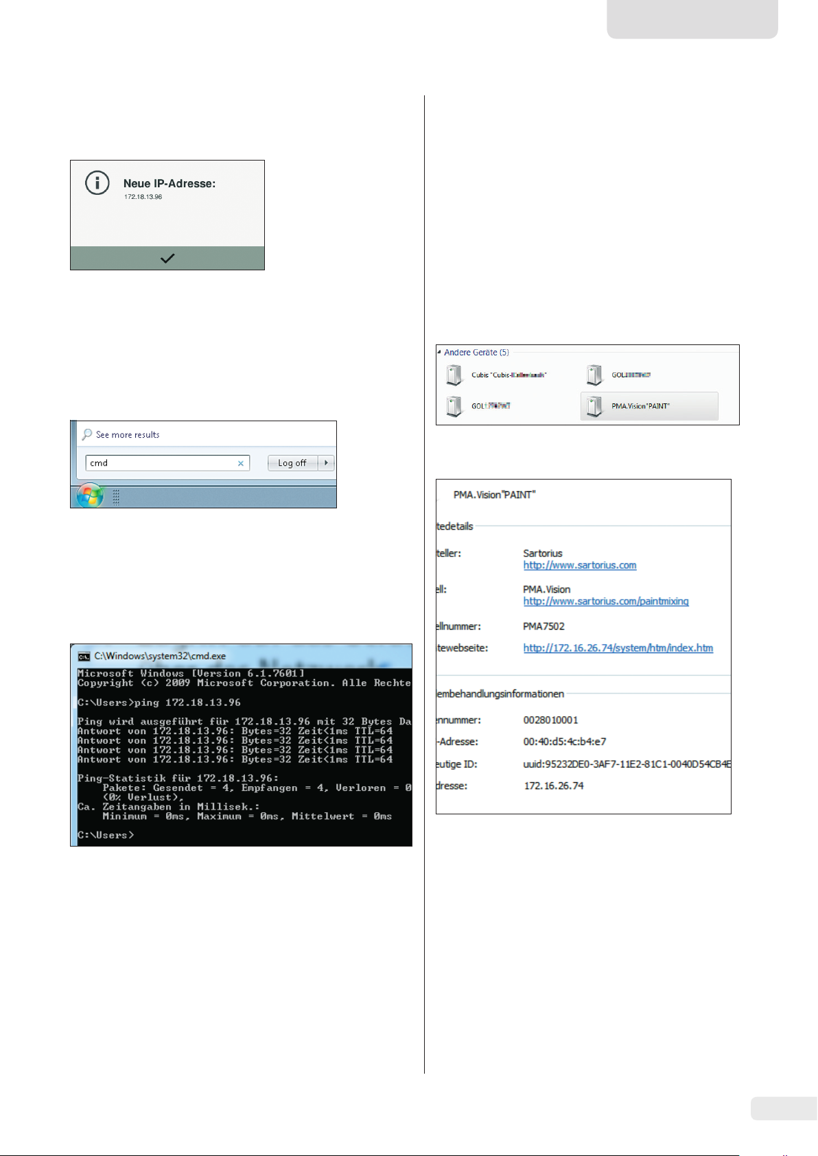
If the IP address of the scale changes, e.g., after the DHCP
server allocates a new address, an info message notifies the
user of the change:
t Confirm this message with the l button.
4.3.1 “Ping” Command
To check whether the network connection is working properly,
send a “ping command” to the scale.
t In the input area of the start menu, enter the command
“cmd.”
4.3.2 Access via UPnP (Universal Plug and Play)
The UPnP protocol allows you to find the scale without
knowing its IP address on the network.
The following requirements must be fulfilled:
− Windows PC (XP SP2 and higher) with enabled UPnP on
the same network. (To enable UPnP, see the
documentation for the installed operating system.)
− Support and activation of the UPnP protocol in the router.
t Open the network devices page in the “Explorer.”
In addition to other UPnP devices, all of the PMA.Vision scales
located on the network are listed under “Other devices:”
t Call up the properties of PMA.Vision “PAINT” by clicking
with the right mouse button.
t Enter the command “ping” in the Windows command
console followed by a space and the IP address of the
scale.
t Confirm the entry with [Enter].
The following figure illustrates what successful detection of
the scale looks like.
t If the network connection does not work, contact your
administrator.
All of the important information about the scale is shown
here.
The device side of the scale can be called up directly in the
web browser by double-clicking on [PMA.Vision “PAINT”].
Installation Instructions VIS1X 11
Page 12
4.3.3 Web Browser Access
When the network connection is properly configured, the
scale can be accessed using a web browser from any device on
the network. The IP address or the name of the scale is needed
for this.
Enter one of the following addresses in the address bar of the
web browser:
− http://172.18.13.96/system/htm/index.htm
− http://PAINT/system/htm/index.htm
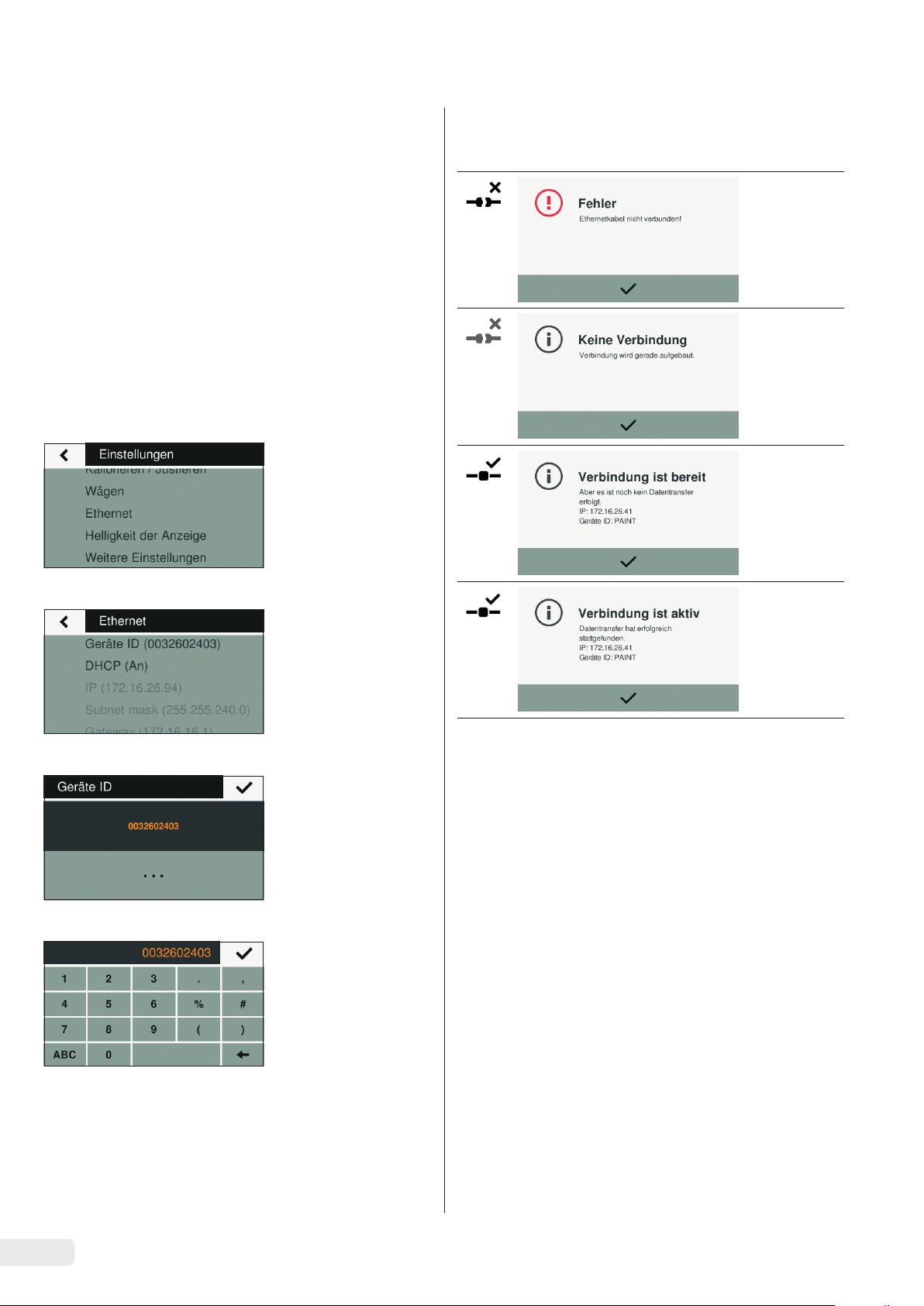
Changing the Device Name of the Scale
The scale appears on the network with a device name (device
ID). The device ID is the serial number by default. Follow these
steps to change the device ID:
t Press the i button to call up the “Settings” menu.
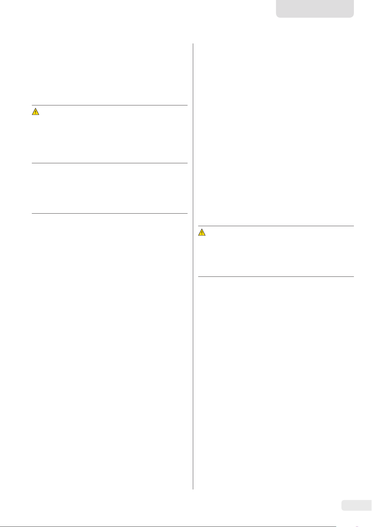
4.4 Overview of the Connection States
Symbol Meaning
t Go into the submenu “Ethernet.”
t Go into the submenu “Device ID.”
t Select “t” to enter a new device ID.
t Enter a new device ID in the displayed input box.
Only letters, numbers, and hyphens may be used.
t Confirm with the l button.
12 Installation Instructions VIS1X
Page 13
English
5 Cleaning and
Maintenance
5.1 Cleaning
Before cleaning the power supply, ex-link converter, or the
scale: Disconnect all devices from the power supply.
WARNING
Electrical hazard from voltage or current.
Disconnect the power supply (if connected) from the mains.
Unplug any connected data cables from the ex-link converter.
Never open the scale or the power supply. The parts contained
in these devices cannot be cleaned, repaired, or replaced by
the user.
NOTICE
Do not clean the following parts with acetone or aggressive
cleaning agents:
− Mains socket
− Data interface
− Labels and all other plastic parts
Procedure
t Disconnect the device from the power supply.
t NOTICE
Make sure that no liquid or dust gets into the scale or the
power supply.
t NOTICE
Corrosion or damage to the device due to unsuitable
cleaning agents!
t Do not use corrosive, chloride-containing, and
aggressive cleaning agents.
t Do not use cleaning agents that contain abrasive
ingredients, e.g. scouring agents, steel wool.
t Only use soft brushes and cloths for cleaning.
t Do not use solvent-based cleaning agents.
5.2 Servicing
To ensure the continued accuracy of your scale, we
recommend scheduling regular servicing at least once a year.
Sartorius Service offers different service contracts with
maintenance intervals that are tailored to your needs.
A calibration certificate should always be issued as part of
every maintenance session. Safety inspections of the power
supply and its connections must be performed at appropriate
intervals by a qualified electrician (e.g. every two years).
6 Disposal
6.1 Information on Decontamination
According to the EU directives [European directive on
hazardous substances], the owners of devices that come
into contact with hazardous substances are responsible for
properly disposing of these devices and for declaring such
devices when transporting them.
WARNING
Risk of injury due to contaminated devices!
Devices contaminated with hazardous materials (NBC
contamination) will not be accepted for repair or disposal.
6.1.1 Information on Disposal
The device and its accessories do not belong in your regular
household waste, since they are made of high-grade materials
which can be recycled and reused. All parts must be disposed
of properly by disposal facilities.
The packaging is made of environmentally friendly materials
that can be used as secondary raw materials.
6.1.2 Disposal
Cleaning the Control Panel
t Before cleaning the control panel: Turn off the device as
touching the screen could trigger unwanted inputs.
Cleaning the Device Housing
t Wipe off the housing with a slightly damp cloth.
For more severe contamination, use a mild soap solution.
t Wipe the device with a soft cloth.
Prerequisites
The device has been decontaminated.
Procedure
t Dispose of the device. Follow the disposal instructions on
our website (www.sartorius.com).
t Dispose of the packaging in accordance with local
government regulations.
Installation Instructions VIS1X 13
Page 14
7 Accessories
8 Serial Number Coding
Accessories Order number
Power supply (5 V/1500 mA) YPS07-USB
USB cable, 3 m
Power plug adapter set for YPS07-USB YAK01
− USA and Japan
− Europe/EU
− United Kingdom
Power plug adapter set for YPS07-USB YAK02
− Australia
− South Africa
− Argentina
− Brazil
Power plug adapter set for YPS07-USB YAK03
− India
− Korea
− China
Ex-link converter
Link cable from converter to scale, 10 m
Link cable from converter to scale, 20 m
Link cable from converter to scale, 30 m
Ethernet patch cable from the converter to
the PC, 5 m
Equipotential bonding cable, 2 m
In-use cover for the control panel,
pack of 10
In-use cover for the support arm,
pack of 10
In-use cover for weighing pan,
pack of 10
CAL weight
− for PMA.Vision, 5 kg,
accuracy class F2
− for PMA.Vision, 2 kg,
accuracy class F2
− for PMA.Vision, 1 kg,
accuracy class F2
YCC01-0040M3
YCO16-Z
YCC01-0052M10
YCC01-0052M20
YCC01-0052M30
YCC01-0044M5
YCC01-X046M2
YDC03PMA10
YDC03PMA-CO10
YDC03PMA-WP10
YCW654-AC-00
YCW624-AC-00
YCW614-AC-00
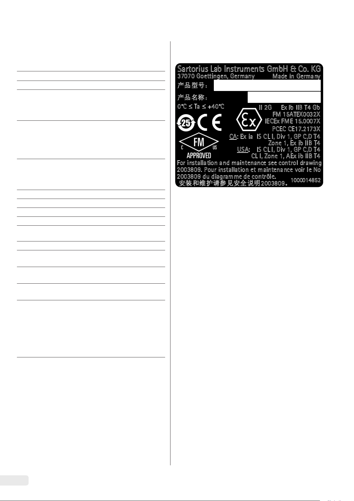
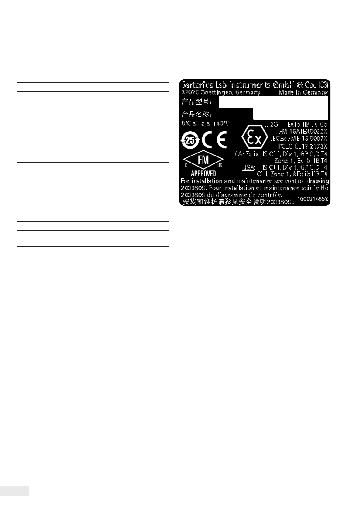
Sartorius Lab Instruments GmbH & Co. KG
37070 Goettingen, Germany
产品型号:
产品名称:PMA威视
0°C Ta +40°C
1725
CA: Ex ia IS CL I, Div 1, GP C,D T4
USA: IS CL I, Div 1, GP C,D T4
CL I, Zone 1, AEx ib IIB T4
For installation and maintenance see control drawing
2003809. Pour installation et maintenance voir le No
2003809 du diagramme de contrôle.
安装和维护请参见安全 说明2003809。
The manufacture date of this device is encoded in the serial
number. The format is as follows:
YMM x x x x x
Y Year
3 2014–2020
4 2021-2027
5 2028-2034, etc.
The Y column indicates the year group, which covers a period
of 7 years. Within each year group, the months (M M) are
counted up from 13.
Year: 2015 2016 2017 2018 2019 ...
MM: 25-36 37-48 49-60 61-72 73-84 ...
Example:
328xxxxx (April 2015): “xxxxx” is a consecutive number, that
resets and starts from one every month.
Made in Germany
II 2G Ex ib IIB T4 Gb
FM 15ATEX0032X
IECEx FME 15.0007X
PCEC CE17.2173X
Zone 1, Ex ib IIB T4
1000014852
14 Installation Instructions VIS1X
Page 15
English
9 Technical Data
9.1 General Data
Specification Unit Value
Scale
Supply voltage Only via Sartorius power supply YPS07-USB
Input voltage V
Power consumption W 5.1
Further data IP40 in accordance with EN 60529/IEC 60529
Ambient conditions
The technical specifications apply under the following ambient conditions:
Environment For indoor use only.
Operational capability °C Guaranteed between +5 and +40.
Storage and shipping °C -10 to +60
Relative humidity % Up to 80% for temperatures up to 30°C non-condensing,
Ex-link converter interface connection Ethernet
Electromagnetic compatibility In accordance with EN 61326-1/IEC 61326-1 Electrical equipment for
Interference resistance Basic requirements
Transient emissions Class B
DC
+5.0
decreasing linearly to 50% relative humidity at 40°C
measurement, control and laboratory use – EMC requirements – Part 1:
General requirements
Suitable for use in residential areas and areas that are connected to
a low voltage network that also supplies residential buildings.
Verified scales in accordance with EU requirements comply with the
requirements of Council Directive 2014/31/EU with EN 45501:2015 and
OIML R76:2006.
* For verified scales in accordance with EU requirements, refer to the
information on the scale.
** For verified scales in accordance with EU requirements, the legal
regulations apply.
Available application programs Recalculation, factor calculation, formula
Power supply YPS07-USB
USB power supply unit (5 V/1500 mA) Type FW7721M (manufacturer description)
Primary 100 — 240 V~, -10% /+10%, 50 — 60 Hz, 200 — 100 mA
Secondary 5 V
Further data Protection class II
Ex-link converter YCO16-Z
Further data IP40 in accordance with EN 60529/IEC 60529
, ± 5%, 1500 mA (max.)
DC
IP40 in accordance with EN 60529/IEC 60529
Installation Instructions VIS1X 15
Page 16

9.2 Model-Specific Data
Specification Unit Value
Weighing capacity g 7500/999.95
Readability g 0.1/0.05
Tare range (subtractive) g -7500
External adjustment weight /
accuracy class
Diameter of weighing pan mm 233
Net weight kg 2.4
kg 1, 2, 5 /
F2 or better
9.3 Verified Models with EU Type Examination Certificate: Model-Specific Specifications
Specification Unit Value
Accuracy class II
Type PMA-EV
Weighing capacity max. g 7500
Weighing capacity min. g 5
Scale interval d g 0.1
Verification scale interval e g 1
Number of scale intervals n 7500
Temperature range °C +10 to +30
Tare equalization range (subtractive)
Nominal load of the load receptor * g 8000
Switch-on zero setting g
Diameter of weighing pan mm 233
< 100% from max. weighing capacity
± 375
* The sum of the max. switch-on zero setting and dead load may not exceed the nominal load of the load receptor.
10 EU Declaration of Conformity
The attached EU Declaration of Conformity hereby confirms compliance of the device with the directives cited.
For verified scales for use in the EEA, the declaration of conformity set out in the conformity assessment (calibration) shall apply.
Please keep it in a safe place.
16 Installation Instructions VIS1X
Page 17

Deutsch
Inhalt
1 Über dieses Dokument...................................17
1.1 Gültigkeit ............................................17
1.2 Darstellungsmittel ...................................17
2 Sicherheitshinweise
2.1 Bestimmungsgemäße Verwendung..................18
2.2 Explosionsschutz.....................................18
2.3 Personalqualifikation ................................18
2.4 Bedeutung dieser Anleitung .........................19
2.5 Einwandfreiheit des Geräts ..........................19
2.6 Arbeiten an der elektrischen Ausrüstung
des Geräts............................................19
2.7 Persönliche Schutzausrüstung.......................19
2.8 Sicherheitshinweise zur Bedienung des Gerätes.....19
3 Installation
3.1 Lieferumfang.........................................20
3.2 Auspacken ...........................................20
3.3 Aufstellort wählen ...................................20
3.4 Waage montieren....................................20
3.5 Erdung anschließen..................................21
3.6 Spannungsversorgung herstellen....................21
3.7 Diebstahlsicherung...................................22
3.8 Anwärmzeit ..........................................22
4 Zugriff auf die Waage über das Netzwerk
4.1 Anschluss an ein Netzwerk mit DHCP ...............22
4.2 Anschluss an ein Netzwerk mit fester IP-Adresse ...23
4.3 Netzwerkverbindung testen .........................24
4.4 Übersicht der Verbindungszustände.................26
...............................................20
......................................18
.............22
1 Über dieses Dokument
1.1 Gültigkeit
Diese Anleitung gilt für Farbmischwaagen der Modelle:
− VIS1X
− VIS1X...EU
1.2 Darstellungsmittel
Der in der Anleitung verwendete Begriff Gerät bezeichnet
immer die Kombination Waage, Netzgerät und Ex-Link
Konverter.
1.2.1 Warnungen
WARNUNG
Kennzeichnet eine Gefährdung, die Tod oder schwere Körperverletzung zur Folge haben kann, wenn sie nicht vermieden
wird.
VORSICHT
Kennzeichnet eine Gefährdung, die eine mittelschwere oder
leichte Körperverletzung zur Folge haben kann, wenn sie nicht
vermieden wird.
ACHTUNG
Kennzeichnet eine Gefährdung, die Sachschäden zur Folge
haben kann, wenn sie nicht vermieden wird.
5 Reinigung und Wartung
5.1 Reinigen..............................................27
5.2 Warten ...............................................27
6 Entsorgung
6.1 Hinweise zur Dekontamination......................27
7 Zubehör
8 Codierung der Seriennummer
9 Technische Daten
9.1 Allgemeine Daten....................................29
9.2 Modellspezifische Daten.............................30
9.3 Geeichte Modelle mit EU-Baumusterprüfbe-
10 EU-Konformitätserklärung
...............................................27
...................................................28
scheinigung: Modellspezifische technische Daten...30
.................................27
...........................28
........................................29
..............................30
1.2.2 Weitere Darstellungsmittel
t
y
[ ] Verweis auf Bedien- und Anzeigeelemente
Abbildungen der Bedienanzeige
Die Abbildungen in dieser Anleitung basieren auf „Standard“-Waagen. Bei den geeichten Waagen können einige
Anzeigedarstellungen und Protokolle von den Abbildungen
etwas abweichen. Wo dies für den Betrieb von Bedeutung ist,
werden die Unterschiede im Text erläutert.
Handlungsanweisung: Beschreibt Tätigkeiten, die
ausgeführt werden müssen.
Ergebnis: Beschreibt das Ergebnis der ausgeführten Tätigkeiten.
Dieses Symbol gibt einen Hinweis für den eichpflichtigen Verkehr für konformitätsbewertete
(geeichte) Waagen.
Im weiteren Text steht der Begriff ‚geeicht‘ für
den Fachausdruck konformitätsbewertet.
Installationsanleitung VIS1X 17
Page 18

2 Sicherheitshinweise
2.1 Bestimmungsgemäße Verwendung
Die Waage dient zum Mischen von Farben und Lacken. Die
Waage wird mit dem stets außerhalb des explosionsgefährdeten Bereiches zu installierenden Ex-Link Konverters YCO16-Z
nur durch das mitgelieferte Link-Kabel verbunden. Die Waage
kann im explosionsgefährdeten Bereich der Zone 1 eingesetzt
werden. Zur Aufnahme der Materialien müssen geeignete
Gefäße verwendet werden.
Die Waage wird über das Bediendisplay gesteuert. Dabei
können Rezepte mit Hilfe einer Web-Applikation über Tablet,
Smartphone oder PC in die Waage geschrieben werden. Der
PC wird dabei entweder über das Netzwerk oder über ein
Ethernet Kabel direkt mit dem außerhalb des explosionsgefährdeten Bereichs installierten Ex-Link Konverter verbunden.
Das Gerät nur in Gebäuden verwenden.
Das Gerät nur mit den Ausstattungen und unter Betriebsbe-
dingungen einsetzen wie sie in den Technischen Daten
beschrieben sind. Das Gerät nicht umbauen oder technisch
verändern.
Die Anleitung ist Teil des Geräts. Das Gerät ist ausschließlich
für den Einsatz gemäß dieser Anleitung bestimmt.
Jede weitere Verwendung gilt als nicht bestimmungsgemäß.
Wenn das Gerät nicht bestimmungsgemäß eingesetzt wird:
Die Schutzvorrichtungen des Geräts können beeinträchtigt
werden. Dies kann zu Personenschäden und Sachschäden
führen.
Bei Verwendung in Anlagen und Umgebungs bedingungen mit
erhöhten Sicherheitsanforderungen die Auflagen und Bestimmungen Ihres Landes beachten.
2.2 Explosionsschutz
Wird das Gerät außerhalb der Bundesrepublik Deutschland
verwendet, so sind die entsprechenden nationalen Gesetze /
Vorschriften zu beachten. Den Händler oder Sartorius Service
nach den in seinem Land geltenden Richtlinien fragen.
Verwendung im Geltungsbereich der europäischen
ATEX-Richtlinie:
− Bei dem Modell der Reihe VIS1X handelt es sich gemäß
Richtlinie 2014/34/EU um ein Gerät der Kategorie 2, das
für den Einsatz im explosionsgefährdeten Bereich der
Zone 1 geeignet ist.
− Der Ex-Link Konverter YCO16-Z ist ein zugehöriges
elektrisches Betriebsmittel, welches nur außerhalb des
explosionsgefährdeten Bereiches installiert werden darf.
− Die Kennzeichnungen der Geräte sind den EU-Type
Examination Certificates (EU-Baumusterprüfbescheinigungen) ab Seite 73 zu entnehmen. Die Sicherheitshinweise
gemäß der Zeichnung 2003810 ab Seite 73 sind zu
befolgen.
Verwendung in Kanada und in den USA:
− Die eigensicheren Waagen der Modellreihen VIS1X sind
geeignet für den Einsatz in Class I, Division 1 sowie Class I,
Zone 1.
− Der Ex-Link Konverter YCO16-Z ist ein zugehöriges
elektrisches Betriebsmittel, welches nur außerhalb des
explosionsgefährdeten Bereiches installiert werden darf.
− Die Certificates of Compliance 3055566 sowie die Control
Drawing 2003809 ab Seite 73 sind zu beachten.
Verwendung in Australien / Neuseeland:
Das IECEx Certificate of Conformity IECEx FME 15.0007X
sowie die Safety Instructions 2003810 ab Seite 73 sind zu
beachten.
Einsatzbedingungen für das Gerät
Das Gerät nur in Gebäuden verwenden.
Das Gerät nur mit den Ausstattungen und unter Betriebsbe-
dingungen einsetzen wie sie in den technischen Daten dieser
Anleitung beschrieben sind.
Das Gerät nicht eigenmächtig umbauen oder technisch
verändern. Umbaumaßnahmen und technische Änderungen
am Gerät sind nur nach einer vorherigen schriftlichen
Genehmigung durch Sartorius gestattet.
Das Gerät sowie das von Sartorius gelieferte Zubehör nicht
extremen Temperaturen, aggressiven chemischen Dämpfen,
Feuchtigkeit, Stößen, Vibrationen oder starken elektromagnetischen Feldern aussetzen. Einsatzbedingungen gemäß den
Technischen Daten einhalten!
Die Verbindungskabel zwischen den Geräten sowie die
Ummantelung der Litzen der inneren Verdrahtungen bestehen
aus PVC-Materialien. Chemikalien, die diese Materialien
angreifen, müssen von diesen Leitungen ferngehalten werden.
18 Installationsanleitung VIS1X
2.3 Personalqualifikation
Diese Anleitung richtet sich an die unten genannten Zielgruppen. Alle Personen, die am Gerät arbeiten, müssen über die
genannten Kenntnisse und Zuständigkeiten verfügen.
Wenn bei den beschriebenen Tätigkeiten in dieser Anleitung
keine Qualifikation angegeben ist: Die beschriebenen Tätigkeiten richten sich an die Zielgruppe „Bediener“.
Wenn einzelne Tätigkeiten durch andere Zielgruppen oder den
Sartorius Service ausgeführt werden müssen: Die benötigte
Qualifikation ist bei der Beschreibung der Tätigkeit
angegeben.
Page 19
Deutsch
Zielgruppe Kenntnisse und Zuständigkeiten
Bediener Der Bediener ist mit dem Betrieb des Geräts und
den damit verbundenen Arbeitsprozessen vertraut. Er kennt die Gefahren, die bei Arbeiten
mit dem Gerät auftreten können und kann diese
Gefahren vermeiden.
Der Bediener ist in den Betrieb des Geräts eingewiesen. Die Einweisung erfolgt im Rahmen
der Inbetriebnahme und wird durch den
Betriebsingenieur / Laborleiter oder den Betreiber des Geräts durchgeführt.
Betriebsingenieur /
Laborleiter
Elektrofachkraft
Betreiber Der Betreiber des Geräts ist für die Einhaltung
Der Betriebsingenieur / Laborleiter entscheidet
über den Einsatz und die Parametrierung des
Geräts.
Der Betriebsingenieur / Laborleiter ist in den
Betrieb des Geräts eingewiesen. Die Einweisung
erfolgt im Rahmen der Inbetriebnahme und
wird durch den Sartorius Service oder den
Betreiber durchgeführt.
Die Elektrofachkraft kann aufgrund ihrer fachlichen Ausbildung, Kenntnisse und Erfahrungen
sowie Kenntnis der einschlägigen Bestimmungen die ihr übertragenen Arbeiten beurteilen
und mögliche Gefahren erkennen.
der Sicherheits- und Arbeitsschutzbestimmungen zuständig.
Der Betreiber muss sicherstellen, dass alle Personen, die am Gerät arbeiten, Zugang zu den relevanten Informationen haben und in die Arbeit
am Gerät eingewiesen sind.
2.4 Bedeutung dieser Anleitung
Die Nichtbeachtung der Anleitung kann ernste Folgen haben,
z. B. Gefährdung von Personen durch elektrische, mechanische
oder chemische Einflüsse.
t Vor allen Arbeiten am Gerät die Anleitung aufmerksam
und vollständig durchlesen.
t Bei Verlust der Anleitung Ersatz anfordern oder die
aktuelle Anleitung von der Sartorius-Internetseite herunterladen (www.sartorius.com).
t Die Informationen aus der Anleitung müssen für alle
Personen verfügbar sein, die am Gerät arbeiten.
2.5 Einwandfreiheit des Geräts
Ein beschädigtes Gerät kann zu Fehlfunktionen führen oder
schwer erkennbare Gefährdungen hervorrufen.
2.6 Arbeiten an der elektrischen Ausrüstung des Geräts
Jegliche Arbeiten und Modifikationen an der elektrischen
Ausrüstung des Geräts dürfen nur vom Sartorius Service
vorgenommen werden. Das Gerät darf nur vom Sartorius
Service geöffnet werden.
Versiegelungsmarke an geeichten Varianten
Der Gesetzgeber fordert eine Versiegelung der
geeichten Waage. Diese Versiegelung erfolgt
mittels einer Klebemarke mit Namenszug „Sartorius“. Wird sie entfernt, erlischt die Eichgültigkeit
und die Waage muss geeicht werden. Bei geeichten Waagen für den Einsatz im EWR gilt die bei
der Eichung ausgestellte und der Waage beigelegte Konformitätserklärung. Bitte unbedingt
aufbewahren.
2.7 Persönliche Schutzausrüstung
Die persönliche Schutzausrüstung schützt vor Gefährdungen
durch die verarbeiteten Materialien.
t Wenn der Arbeitsbereich oder der Prozess, in dem das
Gerät eingesetzt wird, eine persönliche Schutzausrüstung
erfordert: Die persönliche Schutzausrüstung tragen.
2.8 Sicherheitshinweise zur Bedienung des Gerätes
− Die Glasscheibe des Bediendisplays nicht beschädigen (z. B.
durch herabfallende Gegenstände, Schläge oder starken
Druck). Wird die Glasscheibe beschädigt, ist das Gerät
sofort vom Netz zu trennen!
− Die Oberfläche des Bediendisplays nicht mit spitzen,
scharfen, harten oder rauen Gegenständen berühren,
sondern ausschließlich mit einem dafür vorgesehenen
Touchpen oder mit den Fingerspitzen. Zum Reinigen
keinesfalls Teile der Kleidung (z. B. Jackenärmel) oder
Schwämme verwenden, da diese die Oberfläche zerkratzen
können (z. B. durch Nieten oder Knöpfe im Jackenärmel
oder Sand in Schwämmen).
− Elektrostatische Aufladung der Glasscheibe des Bediendisplays und des Kunststoffgehäuses vermeiden.
Beschädigungsgefahr der Waage!
Verschließen Sie nie die Farbdose mit einem
Hammer, solange diese auf der Waagschale
steht.
Stellen Sie die Farbdose zum Verschließen auf
einen festen stabilen Untergrund.
t Das Gerät nur in sicherheitstechnisch einwandfreiem
Zustand betreiben.
t Beschädigtes Gerät sofort spannungslos schalten.
t Beschädigungen umgehend durch den Sartorius Service
beheben lassen.
Installationsanleitung VIS1X 19
Page 20
3 Installation
3.1 Lieferumfang
3.4 Waage montieren
ACHTUNG
Für alle Montagearbeiten muss das Gerät von der Spannungsversorgung getrennt sein.
Artikel Menge
Waagschale groß: d 233 mm
USB Kabel, 3 m 1
Netzgerät YPS07-USB 1
Ex-Link Konverter 1
Link-Kabel vom Konverter zur Waage 1
Installationsanleitung 1
1
3.2 Auspacken
Vorgehen
t Öffnen Sie die Verpackung und entnehmen Sie vorsichtig
alle Teile.
t Überprüfen Sie das Gerät nach dem Auspacken sofort auf
äußere Beschädigungen.
t Wenn das Gerät zwischengelagert wird: Das Gerät gemäß
den Umgebungsbedingungen lagern (Umgebungsbedingungen siehe Kapitel „9.1 Allgemeine Daten“, Seite 29
t Bewahren Sie alle Teile der Originalverpackung für einen
eventuellen Rücktransport auf. Lassen Sie beim Versand
keine Kabel stecken!
t Setzen Sie die Waagschale von
oben auf die Waage auf.
3.4.1 Waage anschließen
t Stecken Sie den Stecker des
Link-Kabels auf der Rückseite
des Displays in die Buchse.
t Verlegen Sie das Link-Kabel
durch die Kabelhalter auf der
Rückseite der Waage.
3.3 Aufstellort wählen
Den richtigen Standort wählen:
− Das Gerät auf eine stabile, erschütterungsarme, gerade
Fläche stellen.
− Zugang zu dem Gerät jederzeit freihalten.
Bei der Aufstellung Standorte mit ungünstigen Einflüssen
vermeiden:
− Hitze (Heizung, Sonneneinstrahlung)
− Direkter Luftzug durch offene Fenster, Klimaanlagen und
Türen
− Erschütterungen während der Messung
− Kein „Personendurchgangsverkehr“
− Extrem hohe Luftfeuchtigkeit
− Elektromagnetische Felder
− Extrem trockene Luft
Akklimatisieren
Wenn ein kaltes Gerät in eine warme Umgebung gebracht
wird kann dies zu Kondensation von Luftfeuchtigkeit führen
(Betauung). Daher akklimatisieren Sie das vom Netz getrennte
Gerät ca. 2 Stunden, bevor Sie es wieder an die Versorgungsspannung anschließen.
t Schließen Sie das Link-Kabel
am Ex-Link Konverter an.
Anschluss an Personalcomputer/
Notebook
t Stecken Sie ein Ethernetka-
bel (1) in den Ex-Link Konverter
und verbinden Sie das Kabel
1
mit einem Windows-PC
(Direktverbindung) oder an das
Netzwerk.
20 Installationsanleitung VIS1X
Page 21
Deutsch
3.5 Erdung anschließen
Benötigte Qualifikation: Elektrofachkraft
Die explosionsgeschützte Anlage nach den anerkannten
Regeln der Technik errichten. Dabei sind die entsprechenden
nationalen Gesetze / Vorschriften zu beachten.
Vor Inbetriebnahme der Waage muss der ordnungsgemäße
Zustand durch eine Elektrofachkraft oder unter Leitung und
Aufsicht einer Elektrofachkraft überprüft werden.
Prüfen Sie, ob die zuständigen Behörden (z. B. Gewerbeaufsichtsamt) informiert werden müssen. Auch während des
Betriebes sind Prüfungen der Anlage erforderlich.
Die Fristen dazu sind so zu bemessen, dass entstehende
Mängel, mit denen gerechnet werden muss, rechtzeitig
erkannt werden. Die Prüfungen sind mindestens alle drei Jahre
durchzuführen. Während des Betriebes sind die entsprechenden Auflagen und Richtlinien zu erfüllen.
Die Anlage erstmalig nur dann in Betrieb nehmen, wenn
sichergestellt ist, dass der Bereich nicht explosionsgefährdet
ist.
Zeigen sich bei dieser Inbetriebnahme durch Transportschäden
Abweichungen (z. B. keine Anzeige, keine Hintergrundbeleuchtung), so ist die Waage vom Netz zu trennen und der
Sartorius Service zu informieren.
Die Installation muss von einer dafür ausgebildeten Elektrofachkraft vorschriftsmäßig und nach den Regeln der Technik
durchgeführt werden.
Verbinden Sie die Waage mit
einem Potenzialausgleichskabel
von mindestens 4 mm² Querschnitt
mit dem Potenzialausgleich.
3.6 Spannungsversorgung herstellen
Benötigte Qualifikation: Elektrofachkraft
Die Spannungsversorgung der Waage erfolgt durch das
Netzgerät YPS07-USB (siehe Kapitel „7 Zubehör“, Seite 28),
das mit verschiedenen länderspezifischen Netzadaptern
geliefert wird.
ACHTUNG
− Der auf dem Netzgerät aufgedruckte Spannungswert muss
mit der lokalen Netzspannung übereinstimmen (Anschlussdaten siehe Kapitel „9.1 Allgemeine Daten“, Seite 29).
− Sollte die angegebene Netzspannung oder die Steckerausführung des Netz gerätes nicht der verwendeten Ländernorm entsprechen, verständigen Sie bitte die nächste
Sartorius-Vertretung.
Der Zusammenbau des Netzgerätes ist im Folgenden
beschrieben.
3.6.1 Netzgerät montieren
WARNUNG Tödliche Stromschläge und Geräteschäden
t
durch falsche Netzsteckeradapter! Nur den länderspezifischen Netzsteckeradapter verwenden. Den Netzsteckeradapter nie getrennt vom Netzgerät in die Steckdose stecken.
t Verwenden Sie den zu Ihrem Stromnetz passenden
Netzadapter:
t Schließen Sie den Kabelschuh
des Potenzialausgleichskabels
an die Erdungsklemme der
Waage an.
t Schließen Sie das Potenzialaus-
gleichskabel an den kundenseitigen Potenzialausgleich an.
Verbinden Sie den Ex-Link Konverter mit einem weiteren Potenzialausgleichskabel von mindestens
4 mm² Querschnitt mit dem Potenzialausgleich.
t Schließen Sie den Kabelschuh
des Potenzialausgleichskabels
an die Erdungsklemme des
Ex-Link Konverters an.
t Schließen Sie das Potenzialaus-
gleichskabel an den kundenseitigen Potenzialausgleich an.
Netzadapterset YAK01
Beutel Region/Land
a) transparent Europa/EU (außer Großbritannien)
b) blau USA
c) gelb Großbritannien
Netzadapterset YAK02
Beutel Region/Land
d) rot Australien
e) türkis Südafrika
f) weiß Argentinien
g) rosa Brasilien
Installationsanleitung VIS1X 21
Page 22
Netzadapterset YAK03
0
30
3.7 Diebstahlsicherung
Beutel Region/Land
h) hellbraun China
i) schwarz Indien
j) grün Korea
t Drücken (1) und schieben (2)
Sie den für Ihre Stromversorgung erforderlichen Netzadapter in die Öffnung des Netzgerät-Moduls.
Der Netzadapter muss dabei
einrasten.
Netzadapter
demontieren / tauschen
t Entriegeln (1) Sie den Netz-
adapter und ziehen (2) Sie
ihn ab.
t Sichern Sie die Waage bei
Bedarf an der Rückseite.
3.8 Anwärmzeit
Um genaue Resultate zu liefern,
benötigt die Waage eine Anwärmzeit von mindestens 30 Minuten
nach erstmaligem Anschluss an die
Spannungsversorgung. Erst dann
hat das Gerät die notwendige
Betriebstemperatur erreicht.
4 Zugriff auf die Waage
über das Netzwerk
Netzanschluss / Schutzmaßnahmen
− Nur Originalnetzgeräte von Sartorius verwenden.
Die Schutzart des Netzgerätes entspricht IP40 gemäß
EN60529 / IEC60529.
− Der aufgedruckte Spannungswert muss mit der örtlichen
Spannung übereinstimmen.
− Sollte die angegebene Netzspannung oder die Steckerausführung des Netz gerätes nicht der verwendeten Ländernorm entsprechen, verständigen Sie bitte die nächste
Sartorius-Vertretung.
− Der Netzanschluss muss gemäß den Bestimmungen Ihres
Landes erfolgen.
Anschluss an Netzgerät
t Stecken Sie ein USB Kabel (2)
in den Ex-Link Konverter.
2
t Stecken Sie das USB Kabel in das
Netzgerät YPS07-USB.
t Stecken Sie das Netzgerät in
eine Steckdose (Netzspannung).
4.1 Anschluss an ein Netzwerk mit DHCP
Üblicherweise wird die IP-Adresse in einem Netzwerk durch
einen DHCP-Server (Dynamic Host Configuration Protocol)
vergeben. Vorraussetzung dafür ist, das an der Waage der
DHCP-Modus eingeschaltet ist.
t Rufen Sie über die Taste i das Menü „Einstellungen“ auf.
t Rufen Sie das Untermenü „Ethernet“ auf.
22 Installationsanleitung VIS1X
Steht in der Anzeige „DHCP (An)“, sind die Einstellungen
korrekt.
Page 23

t Andernfalls rufen Sie das Untermenü „DHCP“ auf.
t Wählen Sie „An“.
t Bestätigen Sie die Eingabe mit der Taste l.
y Der DHCP-Modus ist nun eingeschaltet.
Beim Einschalten der Waage bekommt die Waage automatisch
durch den DHCP-Server eine IP-Adresse zugeteilt.
t Prüfen Sie die Netzwerkverbindung (siehe Kapitel 4.3,
Seite 24).
Deutsch
4.2 Anschluss an ein Netzwerk mit fester IP-Adresse
Um die Waage an ein Netzwerk mit festen IP-Adressen
anzuschließen müssen folgende Einstellungen vorgenommen
werden:
4.2.1 Netzwerk am PC einstellen
t Rufen Sie die Netzwerkumgebung des Windows-PCs auf:
Start -> Control Panel -> Network and Sharing Center
1
t Öffnen Sie die LAN-Verbindung (1).
2
t Rufen Sie die Eigenschaften (2) der LAN-Verbindung auf.
3
4
t Wählen Sie den Eintrag „Internet Protocol Version 4“ (3)
aus der Liste aus.
t Öffnen Sie die Eigenschaften (4).
Installationsanleitung VIS1X 23
Page 24
t Wählen Sie „Use the following IP adress“ (5).
t Geben Sie die IP-Adresse der Netzwerkverbindung (6) ein.
t Bestätigen Sie die Eingabe mit „OK“ und schließen Sie die
nachfolgenden Fenster jeweils mit „OK“.
4.2.2 Netzwerk an der Waage einstellen
t Rufen Sie über die Taste i das Menü „Einstellungen“ auf.
t Rufen Sie das Untermenü „IP (xxxxxxx)“ auf.
5
6
t Wählen Sie „t“ für die Eingabe einer neuen IP-Adresse.
t Geben Sie über das Eingabefeld eine neue IP-Adresse ein.
Achten Sie dabei darauf:
− eine IP-Adresse aus dem gleichen Adressraum des
Windows-PCs (Subnet Mask) zu verwenden.
− nicht dieselbe IP-Adresse des Windows-PCs zu verwenden.
t Bestätigen Sie die Eingabe mit der Taste l und verlassen
Sie die Einstellungen.
Gegebenenfalls müssen auch die Einstellungen im Untermenü
„Subnet mask“ und „Gateway“ angepasst werden.
t Rufen Sie das Untermenü „Ethernet“ auf.
t Rufen Sie das Untermenü „DHCP“ auf.
t Führen Sie einen Neustart der Waage durch.
t Prüfen Sie die Netzwerkverbindung (siehe Kapitel 4.3,
Seite 24).
4.3 Netzwerkverbindung testen
Die IP-Adresse und die Geräte ID können jederzeit über das
Untermenü „Geräteinformationen“ ermittelt werden.
t Rufen Sie über die Taste i das Menü „Einstellungen“ auf.
t Rufen Sie das Untermenü „Geräteinformationen“ auf.
t Wählen Sie „Aus“.
t Bestätigen Sie die Eingabe mit der Taste l.
y Der DHCP-Modus ist aus eingeschaltet.
24 Installationsanleitung VIS1X
Page 25
Deutsch
Ändert sich die IP-Adresse der Waage, z. B. durch die Vergabe
einer neuen Adresse durch den DHCP-Server, so wird die
Änderung durch eine Info-Message dem Benutzer mitgeteilt:
t Bestätigen Sie die Mitteilung mit der Taste l.
4.3.1 Ping-Befehl
Um zu überprüfen, ob die Netzwerkverbindung korrekt
funktioniert, senden Sie einen „Ping-Befehl“ an die Waage.
t Geben Sie in dem Eingabebereich des Startmenüs den
Befehl „cmd“ ein.
4.3.2 Zugriff über UPnP (Universal Plug and Play)
Das UPnP-Protokoll bietet die Möglichkeit, die Waage ohne
Kenntnis der IP-Adresse im Netzwerk zu finden.
Folgende Vorraussetzung müssen dafür erfüllt sein:
− Windows-PC (ab XP SP2) mit freigeschalteten UPnP in
demselben Netzwerk. (Zur Freischaltung von UPnP siehe
die Dokumentation zu dem installierten Betriebssystem.)
− Unterstützung und Freischaltung des UPnP-Protokolls im
Router.
t Rufen Sie im Explorer die Netzwerkgeräte auf.
Dort werden unter „Andere Geräte“ neben anderen UPnP-Geräten alle im Netzwerk befindlichen PMA.Vision-Waagen
aufgelistet:
t Rufen Sie mit der rechten Maustaste die Eigenschaften der
PMA.Vision „PAINT“ auf.
t Geben Sie in der Windows Eingabekonsole den Befehl
„ping“, gefolgt von einem Leerzeichen und der IP-Adresse
der Waage ein.
t Bestätigen Sie die Eingabe mit der Enter-Taste.
In der folgenden Abbildung wird die erfolgreiche Erkennung
der Waage angezeigt.
t Falls die Netzwerkverbindung nicht funktioniert, wenden
Sie sich an Ihren Administrator.
Hier werden alle wichtige Informationen der Waage
dargestellt.
Durch ein Doppelklick auf [PMA.Vision „PAINT“] kann direkt
die Geräteseite der Waage im Webbrowser aufgerufen
werden.
Installationsanleitung VIS1X 25
Page 26
4.3.3 Zugriff über Webbrowser
Bei korrekter Einrichtung der Netzwerkverbindung, kann die
Waage über einen Webbrowser auf einem beliebigen Gerät im
Netzwerk erreicht werden. Hierfür wird die IP-Adresse oder
der Name der Waage benötigt.
Geben Sie in der Adressleiste des Webbrowser eine der
folgenden Adressen ein:
− http://172.18.13.96/system/htm/index.htm
− http://PAINT/system/htm/index.htm
Gerätename der Waage ändern
Die Waage erscheint im Netzwerk mit einem Gerätenamen
(Geräte ID). Standardmäßig ist als Geräte ID die Seriennummer
eingetragen. Um die Geräte ID zu ändern, gehen Sie folgendermaßen vor:
t Rufen Sie über die Taste i das Menü „Einstellungen“ auf.
4.4 Übersicht der Verbindungszustände
Symbol Bedeutung
t Rufen Sie das Untermenü „Ethernet“ auf.
t Rufen Sie das Untermenü „Geräte ID“ auf.
t Wählen Sie „t“ für die Eingabe einer neuen Geräte ID.
t Geben Sie über das angezeigte Eingabefeld eine neue
Geräte ID ein. Zur Eingabe dürfen nur Buchstaben, Zahlen
und der Bindestrich verwendet werden.
t Bestätigen Sie die Eingabe mit der Taste l.
26 Installationsanleitung VIS1X
Page 27
Deutsch
5 Reinigung und Wartung
5.1 Reinigen
Vor Reinigen des Netzgerätes, des Ex-Link Konverters oder der
Waage: Alle Geräte spannungslos schalten.
WARNUNG Gefahr durch elektrische Span-
nung!
Vorhandenes Netzgerät (optional) vom Netz trennen. Gegebenenfalls angeschlossenes Datenkabel am Ex-Link Konverter
abziehen. Öffnen Sie niemals die Waage oder das Netzgerät.
Diese enthalten keine Geräteteile, die vom Bediener gereinigt,
repariert oder ausgetauscht werden können.
ACHTUNG
Folgende Teile nicht mit Aceton oder aggressiven Reinigungsmitteln reinigen:
− Netzsteckereingang
− Datenschnittstelle
− Schilder sowie alle restlichen Kunststoffteile
Vorgehen
t Das Gerät von der Spannungsversorgung trennen.
t ACHTUNG Darauf achten, dass keine Flüssigkeit oder
Staub in die Waage oder in das Netzgerät gelangen.
t ACHTUNG Korrosion oder Beschädigungen am Gerät
durch ungeeignete Reinigungsmittel!
t Keine ätzenden, chloridhaltigen und aggressiven
Reinigungsmittel verwenden.
t Keine Reinigungsmittel verwenden, die scheuernde
Bestandteile enthalten, z. B. Scheuermilch, Stahlwolle.
t Zur Reinigung nur weiche Bürsten und Putzlappen
verwenden.
t Keine lösemittelhaltigen Reinigungsmittel verwenden.
Bedienfeld reinigen
t Vor dem Reinigen des Bedienfeldes: Das Gerät ausschalten,
da durch die Berührung sonst ungewollt Eingaben
erfolgen können.
Gerätegehäuse reinigen
t Das Gehäuse mit einem leicht feuchten Reinigungstuch
abwischen. Für stärkere Verschmutzungen eine milde
Seifenlauge verwenden.
t Das Gerät danach mit einem weichem Tuch abwischen.
5.2 Warten
Um die fortdauernde Messsicherheit Ihrer Waage zu gewährleisten, empfehlen wir die regelmäßige, mindestens jährliche
Wartung. Der Sartorius Service bietet Ihnen hierzu unterschiedliche Wartungsverträge an, die wir individuell an Ihre
Bedürfnisse anpassen.
Im Rahmen jeder Wartung sollte immer ein Kalibrierzertifikat
erstellt werden. Lassen Sie eine sicherheitstechnische Überprüfung des Netzgerätes und dessen Anschlüsse in angemessenen
Abständen von einer Elektrofachkraft durchführen (z. B. alle
2 Jahre).
6 Entsorgung
6.1 Hinweise zur Dekontamination
Gemäß EU-Richtlinien zur Europäischen Gefahrstoffverordnung ist der Eigentümer von Geräten, die mit Gefahrstoffen in
Berührung gekommen sind, für die sachgerechte Entsorgung
und Deklaration bei deren Transport verantwortlich.
WARNUNG
Verletzungsgefahr durch kontaminierte Geräte!
Mit gefährlichen Stoffen kontaminierte Geräte (ABC-Kontamination) werden nicht zur Reparatur und Entsorgung
zurückgenommen.
6.1.1 Hinweise zur Entsorgung
Das Gerät und das Zubehör gehören nicht in den Hausmüll,
denn sie sind aus hochwertigen Materialien hergestellt, die
recycelt und wiederverwendet werden können. Alle Teile
müssen durch Entsorgungseinrichtungen fachgerecht entsorgt
werden.
Die Verpackung besteht aus umweltfreundlichen Materialien,
die als Sekundärrohstoffe dienen können.
6.1.2 Entsorgen
Voraussetzungen
Das Gerät ist dekontaminiert.
Vorgehen
t Das Gerät entsorgen. Dazu die Entsorgungshinweise auf
unserer Internetseite (www.sartorius.com) beachten.
t Die Verpackung gemäß den landesrechtlichen Bestimmun-
gen entsorgen.
Installationsanleitung VIS1X 27
Page 28
7 Zubehör
8 Codierung der
Zubehör Bestellnummer
Netzgerät (5 V / 1500 mA) YPS07-USB
USB Kabel, 3 m
Netzstecker-Adapterset für YPS07-USB YAK01
− USA und Japan
− Europa / EU
− Großbritannien
Netzstecker-Adapterset für YPS07-USB YAK02
− Australien
− Südafrika
− Argentinien
− Brasilien
Netzstecker-Adapterset für YPS07-USB YAK03
− Indien
− Korea
− China
Ex-Link Konverter
Link-Kabel vom Konverter zur Waage, 10 m
Link-Kabel vom Konverter zur Waage, 20 m
Link-Kabel vom Konverter zur Waage, 30 m
Ethernet-Patchkabel vom Konverter zum PC,
5 m
Potenzialausgleichskabel, 2 m
Arbeitsschutzhaube für Bedienfeld,
10er Pack
Arbeitsschutzhaube für Stativ,
10er Pack
Arbeitsschutzhaube für Waagschale,
10er Pack
Justiergewicht
− für PMA.Vision, 5 kg,
Genauigkeitsklasse F2
− für PMA.Vision, 2 kg,
Genauigkeitsklasse F2
− für PMA.Vision, 1 kg,
Genauigkeitsklasse F2
YCC01-0040M3
YCO16-Z
YCC01-0052M10
YCC01-0052M20
YCC01-0052M30
YCC01-0044M5
YCC01-X046M2
YDC03PMA10
YDC03PMA-CO10
YDC03PMA-WP10
YCW654-AC-00
YCW624-AC-00
YCW614-AC-00
Seriennummer
Sartorius Lab Instruments GmbH & Co. KG
37070 Goettingen, Germany
产品型号:
产品名称:PMA威视
0°C Ta +40°C
1725
CA: Ex ia IS CL I, Div 1, GP C,D T4
USA: IS CL I, Div 1, GP C,D T4
CL I, Zone 1, AEx ib IIB T4
For installation and maintenance see control drawing
2003809. Pour installation et maintenance voir le No
2003809 du diagramme de contrôle.
安装和维护请参见安全 说明2003809。
Das Herstelldatum des Gerätes ist in der Seriennummer
codiert. Die Struktur ergibt sich wie folgt:
JMM x x x x x
J Jahr
3 2014–2020
4 2021-2027
5 2028-2034 usw.
Die Jahresspalte J steht für die Jahresgruppennummer, die
einen Zeitraum von jeweils 7 Jahren definiert. Innerhalb jeder
Jahresgruppe werden die Monate (M M) von 13 an
hochgezählt.
Jahr: 2015 2016 2017 2018 2019 ...
MM: 25-36 37-48 49-60 61-72 73-84 ...
Beispiel:
328xxxxx (April 2015). „xxxxx“ ist eine fortlaufende Nummer,
die jeden Monat neu hochgezählt wird.
Made in Germany
II 2G Ex ib IIB T4 Gb
FM 15ATEX0032X
IECEx FME 15.0007X
PCEC CE17.2173X
Zone 1, Ex ib IIB T4
1000014852
28 Installationsanleitung VIS1X
Page 29

Deutsch
9 Technische Daten
9.1 Allgemeine Daten
Angabe Einheit Wert
Waage
Spannungsversorgung nur über Sartorius Netzgerät YPS07-USB
Eingangsspannung V
Leistungsaufnahme W 5,1
Weitere Daten IP40 gemäß EN 60529/IEC 60529
Umgebungsbedingungen
Die technischen Daten gelten bei folgenden Umgebungsbedingungen:
Umgebung Verwendung nur in Innenräumen
Betriebsfähigkeit °C Gewährleistet zwischen +5 bis +40
Lager und Transport °C –10 bis +60
Relative Luftfeuchte % bis zu 80 % für Temperaturen bis zu 30 °C nicht-kondensierend,
Schnittstellenanschluss Ex-Link Konverter Ethernet
Elektromagnetische Verträglichkeit gemäß EN 61326-1/IEC61326-1 Elektrische Mess-, Steuer-, Regel- und
Störfestigkeit Grundanforderungen
Störaussendung Klasse B
DC
+5,0
linear abnehmend bis zu 50 % relativer Luftfeuchte bei 40 °C
Laborgeräte – EMV-Anforderungen – Teil 1: Allgemeine Anforderungen
Geeignet für den Gebrauch im Wohnbereich und Bereichen, die direkt
an ein Niederspannungsnetz angeschlossen sind, das (auch) Wohngebäude versorgt.
Geeichte Waagen gemäß EU entsprechen den Anforderungen der
EG-Richtlinie 2014/31/EU mit EN45501:2015 bzw. OIML R76:2006.
* Bei geeichten Waagen gemäß EU siehe Angaben auf der Waage.
** Bei geeichten Waagen gemäß EU gelten die gesetzlichen Vorschriften.
Wählbare Anwendungsprogramme Rezeptur, Rekalkulation, Faktorverrechnung
Netzgerät YPS07-USB
USB Steckernetzgerät (5 V / 1500 mA) Type FW7721M (Herstellerbezeichnung)
Primär 100 V — 240 V~, –10 % / +10 %, 50 Hz — 60 Hz, 200 mA - 100 mA
Sekundär 5 V
Weitere Daten Schutzklasse II
Ex-Link Konverter YCO16-Z
Weitere Daten IP40 gemäß EN 60529 / IEC 60529
, ± 5 %, 1500 mA (max.)
DC
IP40 gemäß EN 60529 / IEC 60529
Installationsanleitung VIS1X 29
Page 30

9.2 Modellspezifische Daten
Angabe Einheit Wert
Wägebereich g 7500 / 999,95
Ablesbarkeit g 0,1 / 0,05
Tarierbereich (subtraktiv) g –7500
Externer Justiergewichtswert /
Genauigkeitsklasse
Durchmesser der Waagschale mm 233
Nettogewicht kg 2,4
kg 1, 2, 5 /
F2 oder besser
9.3 Geeichte Modelle mit EU-Baumusterprüfbescheinigung: Modellspezifische technische Daten
Angabe Einheit Wert
Genauigkeitsklasse II
Bauart PMA-EV
Wägebereich Max g 7500
Wägebereich Min g 5
Ziffernschritt d g 0,1
Eichwert e g 1
Anzahl der Eichwerte n 7500
Temperaturbereich °C +10 bis +30
Taraausgleichsbereich (subtraktiv)
Nennlast des Lastaufnehmers * g 8000
Einschaltnullstellbereich g
Durchmesser der Waagschale mm 233
< 100% vom maximalen Wägebereich
± 375
* Die Summe aus Max, Einschaltnullstellbereich und Totlast darf die Nennlast des Lastaufnehmers nicht überschreiten.
10 EU-Konformitätserklärung
Mit der beigefügten EU-Konformitätserklärung wird die Übereinstimmung des Geräts mit den benannten Richtlinien erklärt.
Bei geeichten Waagen für den Einsatz im EWR gilt die bei der Konformitätbewertung (Eichung) ausgestellte Konformitätserklä-
rung. Bitte unbedingt aufbewahren.
30 Installationsanleitung VIS1X
Page 31

Français
Table des matières
1 À propos de ce manuel ..................................31
1.1 Validité...............................................31
1.2 Typographie..........................................31
2 Consignes de sécurité
2.1 Utilisation conforme.................................32
2.2 Protection contre les explosions.....................32
2.3 Qualification du personnel ..........................32
2.4 Importance de ce mode d’emploi....................33
2.5 État de l’appareil.....................................33
2.6 Travaux sur l’équipement électrique de l’appareil...33
2.7 Équipement de protection individuelle..............33
2.8 Consignes de sécurité concernant l’utilisation
de l’appareil..........................................33
3 Installation
3.1 Contenu de la livraison ..............................34
3.2 Déballage ............................................34
3.3 Choisir le lieu d’installation..........................34
3.4 Monter la balance ...................................34
3.5 Raccorder la mise à la terre..........................35
3.6 Raccorder l’appareil à l’alimentation électrique.....35
3.7 Système antivol......................................36
3.8 Temps de préchauffage..............................36
4 Accès à la balance par le réseau
4.1 Connexion à un réseau avec DHCP ..................36
4.2 Connexion à un réseau avec une adresse IP fixe ....37
4.3 Tester la connexion réseau...........................38
4.4 Vue d’ensemble des états de connexion . . . . . . . . . . . . . 40
...............................................34
....................................32
........................36
1 À propos de ce manuel
1.1 Validité
Ce manuel d’installation est valable pour les modèles de
balances pour peintures suivants :
− VIS1X
− VIS1X...EU
1.2 Typographie
Le terme « appareil » utilisé dans le manuel désigne toujours
la combinaison de la balance, du bloc d’alimentation et du
convertisseur de jonction antidéflagrant.
1.2.1 Avertissements
AVERTISSEMENT
Signale un danger qui est susceptible d’entraîner la mort ou
des blessures graves s’il n’est pas évité.
ATTENTION
Signale un danger qui est susceptible d’entraîner des blessures
moyennes ou légères s’il n’est pas évité.
AVIS
Signale un danger qui est susceptible de provoquer des
dommages matériels s’il n’est pas évité.
5 Nettoyage et maintenance
5.1 Nettoyage............................................41
5.2 Maintenance .........................................41
6 Recyclage
6.1 Instructions de décontamination....................41
7 Accessoires
8 Codification du numéro de série
9 Caractéristiques techniques
9.1 Caractéristiques générales...........................43
9.2 Caractéristiques techniques spécifiques
9.3 Modèles approuvés pour l’utilisation en
10 Déclaration de conformité UE
. . . . . . . . . . . . . . . . . . . . . . . . . . . . . . . . . . . . . . . . . . . . . . . . . 41
................................................42
aux différents modèles ..............................44
métrologie légale avec approbation CE de type :
caractéristiques techniques spécifiques aux
différents modèles ...................................44
..............................41
........................42
.............................43
..........................44
1.2.2 Autres signes typographiques
t
y
[ ] Référence à des éléments de commande et
Affichage sur l’écran de commande
Les illustrations représentées dans ce manuel se basent sur les
balances « standard ». Si vous utilisez une balance approuvée
pour l’usage en métrologie légale, il se peut que certains
affichages à l’écran et certains rapports diffèrent légèrement
des illustrations représentées. Ces différences sont expliquées
si cela s’avère nécessaire pour le fonctionnement.
Instruction : décrit des actions qui doivent être
effectuées.
Résultat : décrit le résultat des actions qui
viennent d’être effectuées.
d’affichage
Ce symbole donne une indication relative à
l’utilisation en métrologie légale de balances
évaluées conformes (approuvées pour l’utilisation
en métrologie légale).
Par la mention « approuvé pour l’utilisation en
métrologie légale », le texte fait référence à
l’évaluation de la conformité.
Manuel d'installation VIS1X 31
Page 32

2 Consignes de sécurité
2.1 Utilisation conforme
Cette balance sert à mélanger des peintures et des vernis.
Pour raccorder la balance au convertisseur de jonction
antidéflagrant YCO17-Z qui doit toujours être installé hors
de l’atmosphère explosive, utilisez uniquement le câble de
jonction livré. La balance peut être utilisée dans les atmosphères explosives de la zone 1. Utilisez des récipients adaptés
pouvant contenir les matières.
La balance peut être commandée par l’intermédiaire de
l’écran. De plus, il est possible de créer des formules dans la
balance à l’aide d’une application web via une tablette, un
smartphone ou un PC. Pour ce faire, le PC doit être directement connecté au convertisseur de jonction antidéflagrant
installé hors de l’atmosphère explosive via le réseau ou un
câble Ethernet.
Utilisez l’appareil uniquement dans des bâtiments.
Utilisez l’appareil uniquement avec l’équipement et dans les
conditions de fonctionnement qui sont spécifiés dans les
caractéristiques techniques. N’apportez aucune transformation ni aucun changement technique à l’appareil.
Le manuel fait partie intégrante de l’appareil. Lorsque vous
utilisez l’appareil, respectez obligatoirement les instructions
qui se trouvent dans ce manuel.
Toute autre utilisation est considérée comme non conforme.
Si l’appareil n’est pas utilisé de manière conforme : cela peut
nuire aux systèmes de protection de l’appareil et entraîner des
dommages corporels et matériels.
2.2 Protection contre les explosions
Si l’appareil est utilisé hors d’Allemagne, veuillez vous conformer aux lois et directives nationales en vigueur dans le pays.
Consultez votre revendeur ou le Sartorius Service pour en
savoir plus sur les directives en vigueur dans le pays
d’utilisation.
Utilisation dans le cadre du champ d’application de la
directive européenne ATEX :
− Conformément à la directive 2014/34/UE, les modèles de
la série VIS1X sont des appareils de la catégorie 2 adaptés
à une utilisation dans les atmosphères explosives de la
zone 1.
− Le convertisseur de jonction antidéflagrant YCO16-Z est
un matériel électrique associé qui ne doit être utilisé qu’en
dehors de l’atmosphère explosive.
− Les identifications des appareils sont indiquées dans les
certificats d’examen UE de type (EU-Type Examination
Certificates) à partir de la page 73. Respectez les
consignes de sécurité contenues dans le schéma 2003810
à partir de la page 73.
Utilisation au Canada et aux États-Unis :
− Les balances à sécurité intrinsèque de la série VIS1X sont
adaptées à une utilisation en classe I, division 1 et en
classe I, zone 1.
− Le convertisseur de jonction antidéflagrant YCO16-Z est
un matériel électrique associé qui ne doit être utilisé qu’en
dehors de l’atmosphère explosive.
− Respectez les certificats de conformité (Certificates of
Compliance) 3055566 ainsi que le dessin de contrôle
(Control Drawing) 2003809 à partir de la page 73.
Dans des installations et des conditions ambiantes exigeant
des mesures de sécurité accrues, vous devez respecter les
instructions et les dispositions en vigueur dans votre pays.
Conditions d’utilisation de l’appareil
Utilisez l’appareil uniquement dans des bâtiments.
Utilisez l’appareil uniquement avec l’équipement et dans les
conditions de fonctionnement qui sont spécifiés dans les
caractéristiques techniques de ce manuel.
Ne transformez pas l’appareil ou n’en modifiez pas la technique de votre propre chef. Les transformations et modifications techniques apportées à l’appareil nécessitent une
autorisation écrite préalable de Sartorius.
N’exposez pas l’appareil ainsi que les accessoires fournis par
Sartorius à des températures extrêmes, des vapeurs chimiques
agressives, de l’humidité, des chocs, des vibrations ou de forts
champs électromagnétiques. Respectez les conditions d’utilisation conformément aux caractéristiques techniques !
Les câbles de raccordement entre les appareils ainsi que les
gaines des cordons de câblage internes sont en PVC. Les
produits chimiques pouvant endommager ces matériaux
doivent être tenus à l’écart de ces câbles.
Utilisation en Australie / Nouvelle-Zélande :
Respectez le certificat de conformité IECEx (IECEx Certificate
of Conformity) avec la référence IECEx FME 15.0007X, ainsi
que les instructions de sécurité (Safety Instructions) 2003810
à partir de la page 73.
2.3 Qualification du personnel
Ce manuel s’adresse aux groupes cibles mentionnés ci-dessous.
Toutes les personnes qui travaillent sur l’appareil doivent
disposer des connaissances et des compétences mentionnées.
Si aucune qualification n’est indiquée avec les opérations
décrites dans ce manuel : les opérations décrites s’adressent
au groupe cible « Opérateur ».
Si certaines opérations doivent être effectuées par d’autres
groupes cibles ou par le Sartorius Service : la qualification
nécessaire est indiquée dans la description de l’opération.
32 Manuel d'installation VIS1X
Page 33

Français
Groupe cible Connaissances et compétences
Opérateur L’opérateur connaît le fonctionnement de
l’appareil et les processus de travail qui y sont
associés. Il connaît les dangers potentiels lors
du travail avec l’appareil et il est en mesure de
les éviter.
L’opérateur a reçu une formation pour savoir
faire fonctionner l’appareil. Cette formation a
lieu dans le cadre de la mise en service et est
dispensée par l’ingénieur d’exploitation / le
responsable du laboratoire ou par l’exploitant de
l’appareil.
Ingénieur
d’exploita
tion / responsable du
laboratoire
Électricien
qualifié
Exploitant L’exploitant de l’appareil est responsable de faire
L’ingénieur d’exploitation / le responsable du
-
laboratoire prend les décisions concernant
l’utilisation et le paramétrage de l’appareil.
L’ingénieur d’exploitation / le responsable du
laboratoire a reçu une formation pour savoir
faire fonctionner l’appareil. Cette formation a
lieu dans le cadre de la mise en service et est
dispensée par le Sartorius Service ou par
l’exploitant de l’appareil.
L’électricien qualifié peut évaluer les travaux
qui lui sont attribués et identifier les éventuels
dangers grâce à sa formation spécialisée, ses
connaissances et son expérience, ainsi que ses
connaissances des réglementations en vigueur.
respecter les règles de protection et de sécurité
au travail.
L’exploitant doit s’assurer que toutes les per
sonnes qui travaillent sur l’appareil ont accès
aux informations importantes et ont reçu une
formation sur la manière d’utiliser l’appareil.
-
2.6 Travaux sur l’équipement électrique de l’appareil
Seuls des techniciens du Sartorius Service sont autorisés à
effectuer des opérations et des modifications sur l’équipement
électrique de l’appareil. Seuls les membres du Sartorius Service
sont autorisés à ouvrir l’appareil.
Sceau adhésif sur les modèles approuvés pour
l’utilisation en métrologie légale
La législation exige que les balances approuvées
pour l’utilisation en métrologie légale portent
un sceau. Ce sceau est constitué d’une marque
adhésive portant l’inscription « Sartorius ».
Si on l’enlève, l’autorisation pour l’utilisation en
métrologie légale n’est plus valide et la balance
doit faire l’objet d’une nouvelle vérification.
Pour les balances approuvées pour l’utilisation en
métrologie légale au sein de l’EEE, la déclaration
de conformité jointe à la balance et délivrée lors
du calibrage s’applique. Il est obligatoire de la
conserver.
2.7 Équipement de protection individuelle
L’équipement de protection individuelle protège contre les
risques qui émanent des matières traitées.
t Si la zone de travail ou le processus dans lequel l’appareil
est intégré nécessite un équipement de protection
individuelle : portez l’équipement de protection individuelle.
2.8 Consignes de sécurité concernant l’utilisation de l’appareil
2.4 Importance de ce mode d’emploi
Le non-respect du manuel peut avoir des conséquences
graves, par ex. mise en danger des personnes par des évènements électriques, mécaniques ou chimiques.
t Avant toute intervention sur l’appareil, lisez le manuel
avec attention et dans son intégralité.
t En cas de perte du manuel, demandez-en un autre
exemplaire ou téléchargez la version la plus récente sur le
site Internet de Sartorius (www.sartorius.com).
t Toutes les personnes qui travaillent sur l’appareil doivent
avoir accès aux informations contenues dans le manuel.
2.5 État de l’appareil
Un appareil endommagé peut entraîner des dysfonctionnements ou des risques difficilement détectables.
t Utilisez l’appareil uniquement s’il est dans un état tech-
nique irréprochable.
t Si l’appareil est endommagé, mettez-le immédiatement
hors tension.
t En cas de dommages, demandez immédiatement au
Sartorius Service d’y remédier.
− Veillez à ce que la vitre en verre de l’écran de commande
ne soit pas endommagée (par ex. par la chute d’objets,
des coups ou une forte pression). Si la vitre en verre est
endommagée, débranchez immédiatement l’appareil du
secteur !
− Ne touchez pas la surface de l’écran de commande avec
des objets pointus, coupants, durs ou rugueux, mais
exclusivement avec le stylet prévu à cet effet ou du bout
des doigts. Pour nettoyer l’écran, n’utilisez en aucun cas
des parties de vos vêtements (par ex. vos manches) ou des
éponges, car cela pourrait rayer la surface (par ex. à cause
d’œillets ou de boutons sur vos manches ou de sable dans
les éponges).
− Évitez que la vitre en verre de l’écran de commande et le
boîtier en plastique ne soient chargés électrostatiquement.
Risque de dommages sur la balance !
Ne fermez jamais les bidons de peinture avec
un marteau s’ils sont encore posés sur le
plateau de pesée.
Avant de fermer les bidons de peinture,
posez-les sur une surface stable et solide.
Manuel d'installation VIS1X 33
Page 34

3 Installation
3.1 Contenu de la livraison
3.4 Monter la balance
AVIS
Ne branchez pas l’appareil au secteur avant d’avoir terminé le
montage.
Article Quantité
Grand plateau de pesée : d 233 mm
Câble USB, 3 m 1
Bloc d’alimentation YPS07-USB 1
Convertisseur de jonction antidéflagrant 1
Câble de jonction entre le convertisseur et la
balance
Manuel d’installation 1
1
1
3.2 Déballage
Procédure
t Ouvrez l’emballage et retirez toutes les pièces avec
précaution.
t Aussitôt après avoir déballé l’appareil, vérifiez s’il ne
présente aucune détérioration externe visible.
t Si vous entreposez l’appareil temporairement : conservez
l’appareil conformément aux conditions ambiantes
(conditions ambiantes, voir le chapitre « 9.1 Caractéristiques générales », page 43).
t Conservez tous les éléments de l’emballage pour les
retours éventuels. Débranchez tous les câbles avant de
réexpédier l’appareil !
3.3 Choisir le lieu d’installation
t Posez le plateau de pesée sur la
balance par le dessus.
3.4.1 Raccorder la balance
t Branchez la fiche du câble de
jonction au connecteur femelle
à l’arrière de l’écran.
t Insérez le câble de jonction dans
les fixations à l’arrière de la
balance.
t Raccordez le câble de jonction
au convertisseur de jonction
antidéflagrant.
Choisissez un lieu d’installation adapté :
− Posez l’appareil sur une surface plane, stable et sans
vibrations.
− L’accès à l’appareil doit être libre en permanence.
Lors de l’installation, choisissez un emplacement adéquat
afin de ne pas exposer la balance aux influences externes
suivantes :
− Chaleur due à un radiateur ou aux rayons du soleil
− Courants d’air directs causés par des fenêtres ou des portes
ouvertes ou encore par un climatiseur
− Vibrations pendant la pesée
− Passage de personnes
− Humidité de l’air très élevée
− Champs électromagnétiques
− Air très sec
Adapter l’appareil à l’environnement
De la condensation peut se former lorsqu’un appareil froid est
placé dans un environnement plus chaud. Dans ce cas, adaptez
l’appareil débranché du secteur à la température de la pièce
pendant environ deux heures avant de le raccorder au secteur.
Connexion à un PC/ordinateur
portable
t Branchez un câble Ethernet (1)
au convertisseur de jonction
antidéflagrant et reliez le câble
1
à un PC Windows (connexion
directe) ou au réseau.
34 Manuel d'installation VIS1X
Page 35

Français
3.5 Raccorder la mise à la terre
Qualification nécessaire : électricien qualifié
Le système antidéflagrant doit être installé conformément aux
règles techniques reconnues. Veuillez vous conformer pour
cela aux lois et directives nationales en vigueur dans votre
pays.
Avant de mettre la balance en service, faites vérifier par un
électricien qualifié ou bien sous la direction et le contrôle
d’un électricien que le système est dans un état conforme.
Vérifiez si les autorités compétentes (par ex. les services de
l’Inspection du Travail) doivent être informées. Des vérifications sont également nécessaires pendant le fonctionnement
du système.
La périodicité de ces vérifications doit être fixée de telle
manière que l’apparition de défauts éventuels, avec lesquels
il faut toujours compter, puisse être détectée à temps. Ces
vérifications doivent être réalisées au minimum tous les
trois ans. Pendant le fonctionnement, veillez à respecter les
prescriptions et directives correspondantes.
Avant de mettre le système en service pour la première fois,
assurez-vous qu’il n’y a aucun risque d’explosion dans cette
zone.
Lors de la mise en service, s’il se produit des erreurs
provoquées par des dommages dus au transport (par ex. pas
d’affichage, pas de rétroéclairage), débranchez la balance du
secteur et informez-en le Sartorius Service.
Seul un électricien formé en conséquence est autorisé
à effectuer l’installation de manière réglementaire et
conformément aux règles techniques reconnues.
Connectez la balance à la borne
d’équipotentialité à l’aide d’un
câble d’équipotentialité d’au moins
4 mm² de section transversale.
3.6 Raccorder l’appareil à l’alimentation électrique
Qualification nécessaire : électricien qualifié
La balance est alimentée en courant par le bloc d’alimentation
YPS07-USB (voir chapitre « 7 Accessoires », page 42) qui est
livré avec différents adaptateurs secteur spécifiques à divers
pays.
AVIS
− Veillez à ce que la tension indiquée sur le bloc d’alimentation corresponde à la tension d’alimentation secteur sur
votre lieu d’installation (caractéristiques de connexion, voir
le chapitre « 9.1 Caractéristiques générales », page 43).
− Si la tension secteur ou le type de la fiche du bloc d’alimentation ne correspondent pas aux normes en vigueur
dans votre pays, contactez votre représentant Sartorius.
L’assemblage du bloc d’alimentation est décrit ci-après.
3.6.1 Assembler le bloc d’alimentation
AVERTISSEMENT Électrocutions mortelles et dom-
t
mages sur l’appareil en cas d’adaptateur secteur inadapté !
Utilisez uniquement l’adaptateur secteur spécifique au
pays. Ne branchez jamais l’adaptateur secteur dans la prise
de courant s’il n’est pas inséré dans le bloc d’alimentation.
t Utilisez l’adaptateur adapté à votre réseau électrique :
t Raccordez la cosse du câble
d’équipotentialité à la borne de
mise à la terre de la balance.
t Raccordez le câble d’équipo-
tentialité à la borne d’équipotentialité installée dans votre
usine.
Connectez le convertisseur de
jonction antidéflagrant à la borne
d’équipotentialité à l’aide d’un
autre câble d’équipotentialité d’au
moins 4 mm² de section transversale.
t Raccordez la cosse du câble
d’équipotentialité à la borne de
mise à la terre du convertisseur
de jonction antidéflagrant.
t Raccordez le câble d’équipo-
tentialité à la borne d’équipotentialité installée dans votre
usine.
Jeu d’adaptateurs secteur YAK01
Sachet Région/Pays
a) transparent Europe/UE (sauf la Grande-Bretagne)
b) bleu États-Unis
c) jaune Grande-Bretagne
Jeu d’adaptateurs secteur YAK02
Sachet Région/Pays
d) rouge Australie
e) turquoise Afrique du Sud
f) blanc Argentine
g) rose Brésil
Manuel d'installation VIS1X 35
Page 36

Jeu d’adaptateurs secteur YAK03
0
30
3.7 Système antivol
Sachet Région/Pays
h) marron clair Chine
i) noir Inde
j) vert Corée
t Enfoncez (1) et poussez (2)
l’adaptateur secteur dont
vous avez besoin pour votre
alimentation électrique dans
l’ouverture du module du bloc
d’alimentation.
L’adaptateur doit s’enclencher.
Démonter / remplacer l’adaptateur secteur
t Débloquez (1) l’adaptateur et
retirez-le (2).
Raccordement au secteur / mesures de sécurité
− Utilisez uniquement des blocs d’alimentation d’origine
Sartorius.
Le bloc d’alimentation est conforme à l’indice de
protection IP40 selon EN60529 / IEC60529.
− La valeur de tension figurant sur l’appareil doit
obligatoirement correspondre à la tension locale.
− Si la tension secteur ou le type de la fiche du bloc
d’alimentation ne correspondent pas aux normes en
vigueur dans votre pays, contactez votre représentant
Sartorius.
− Le raccordement au secteur doit être réalisé
conformément aux dispositions locales.
Connexion au bloc
d’alimentation
t Raccordez un câble USB (2)
2
au convertisseur de jonction
antidéflagrant.
t Si nécessaire, fixez la balance à
l’aide du système antivol qui se
trouve à l’arrière.
3.8 Temps de préchauffage
Après le premier raccordement au
secteur, la balance a besoin d’un
temps de préchauffage d’au moins
30 minutes afin de pouvoir fournir
des résultats précis. L’appareil
n’atteint la température de fonctionnement nécessaire qu’après ce
délai.
4 Accès à la balance
par le réseau
4.1 Connexion à un réseau avec DHCP
t Normalement, l’adresse IP dans un réseau est attribuée par
un serveur DHCP (Dynamic Host Configuration Protocol) à
condition que le mode DHCP soit activé sur la balance.
t Appuyez sur la touche i pour ouvrir le menu « Réglages ».
t Ouvrez le sous-menu « Ethernet ».
t Raccordez le câble USB au bloc
t Branchez le bloc d’alimentation
36 Manuel d'installation VIS1X
d’alimentation YPS07-USB.
dans une prise électrique
(tension électrique).
Si « DHCP (On) » est affiché, tous les réglages sont corrects.
Page 37

t Dans le cas contraire, ouvrez le sous-menu « DHCP ».
t Sélectionnez « On ».
t Appuyez sur la touche l pour confirmer la saisie.
y Le mode DHCP est désormais activé.
Lors de la mise en marche de la balance, le serveur DHCP lui
affecte automatiquement une adresse IP.
t Vérifiez la connexion réseau (voir chapitre 4.3, page 38).
Français
4.2 Connexion à un réseau avec une adresse IP fixe
Pour connecter la balance à un réseau avec des adresses IP
fixes, il faut effectuer les réglages suivants :
4.2.1 Régler le réseau sur le PC
t Ouvrez le Voisinage réseau du PC Windows :
Démarrer -> Panneau de configuration -> Centre Réseau
et partage
1
t Ouvrez la Connexion réseau local (1).
2
t Ouvrez les propriétés (2) de la connexion au réseau local.
3
4
t Sélectionnez l’entrée « Internet Protocol Version 4 » (3)
dans la liste.
t Ouvrez les propriétés (4).
Manuel d'installation VIS1X 37
Page 38

t Sélectionnez « Utiliser l’adresse IP suivante » (5).
t Saisissez l’adresse IP de la connexion réseau (6).
t Appuyez sur « OK » pour confirmer la saisie et fermez les
fenêtres suivantes en appuyant à chaque fois sur « OK ».
4.2.2 Régler le réseau sur la balance
t Appuyez sur la touche i pour ouvrir le menu « Réglages ».
t Ouvrez le sous-menu « IP (xxxxxxx) ».
5
6
t Sélectionnez « t » pour saisir une nouvelle adresse IP.
t Entrez une nouvelle adresse IP dans le champ de saisie
en veillant à :
− utiliser une adresse IP du même espace d’adressage du
PC Windows (Masque de sous-réseau).
− ne pas utiliser la même adresse IP du PC Windows.
t Appuyez sur la touche l pour confirmer la saisie et
quittez les réglages.
Le cas échéant, il faut également adapter les réglages dans le
sous-menu « Masque de sous-réseau » et « Passerelle ».
t Redémarrez la balance.
t Vérifiez la connexion réseau (voir chapitre 4.3, page 38).
t Ouvrez le sous-menu « Ethernet ».
t Ouvrez le sous-menu « DHCP».
t Sélectionnez « Off ».
t Appuyez sur la touche l pour confirmer la saisie.
y Le mode DHCP est désormais désactivé.
4.3 Tester la connexion réseau
L’adresse IP et l’ID de l’appareil peuvent être déterminés à tout
moment dans le sous-menu « Infos sur l’appareil ».
t Appuyez sur la touche i pour ouvrir le menu « Réglages ».
t Ouvrez le sous-menu « Infos sur l’appareil ».
38 Manuel d'installation VIS1X
Page 39

Français
Si l’adresse IP de la balance change, par ex. parce que le
serveur DHCP lui attribue une nouvelle adresse, un message
d’information signale le changement à l’utilisateur :
t Appuyez sur la touche l pour confirmer le message.
4.3.1 Commande ping
Pour contrôler si la connexion réseau fonctionne correctement,
vous devez envoyer une « commande ping » à la balance.
t Entrez la commande « cmd » dans le champ de saisie du
menu de démarrage.
4.3.2 Accès via UPnP (Universal Plug and Play)
Le protocole UPnP permet de trouver la balance dans le réseau
sans connaître l’adresse IP.
Pour cela, il faut que les conditions suivantes soient remplies :
− PC Windows (à partir de XP SP2) avec UPnP activé dans
le même réseau (pour l’activation de UPnP, voir la documentation du système d’exploitation installé).
− Prise en charge et activation du protocole UPnP dans le
routeur.
t Dans l’Explorateur, ouvrez les Périphériques réseau.
Toutes les balances PMA.Vision qui sont dans le réseau y
sont regroupées sous « Autres appareils » à côté des autres
appareils UPnP :
t Avec la touche droite de la souris, ouvrez les propriétés de
la PMA.Vision "PAINT".
t Dans la console de saisie Windows, entrez la commande
« ping » suivie d’un espace et de l’adresse IP de la balance.
t Appuyez sur la touche Entrée pour confirmer la saisie.
L’illustration qui suit montre la détection réussie de la
balance.
t Si la connexion réseau ne fonctionne pas, veuillez vous
adresser à votre administrateur.
Toutes les informations importantes de la balance y sont
inscrites.
Pour ouvrir directement la page de la balance dans le
navigateur, double-cliquez sur [PMA.Vision « PAINT »].
Manuel d'installation VIS1X 39
Page 40

4.3.3 Accès via le navigateur web
Si la connexion réseau est correctement configurée, il est
possible d’avoir accès à la balance via un navigateur Web sur
un appareil au choix dans le réseau. L’adresse IP ou le nom de
la balance sont nécessaires.
Saisissez une des adresses suivantes dans la barre d’adresses
du navigateur web :
− http://172.18.13.96/system/htm/index.htm
− http://PAINT/system/htm/index.htm
Changer le nom de la balance
La balance apparaît dans le réseau avec un nom d’appareil
(ID appareil). L’ID par défaut de l’appareil est le numéro de
série. Pour modifier l’ID de l’appareil, procédez comme suit :
Appuyez sur la touche i pour ouvrir le menu « Réglages ».
4.4 Vue d’ensemble des états de connexion
Symbole Signification
t Ouvrez le sous-menu « Ethernet ».
t Ouvrez le sous-menu « ID appareil ».
t Sélectionnez « t » pour saisir un nouvel ID pour l’appareil.
t Entrez un nouvel ID dans le champ de saisie affiché.
Vous devez utiliser uniquement des lettres, des chiffres
et le trait d’union.
t Appuyez sur la touche l pour confirmer la saisie.
40 Manuel d'installation VIS1X
Page 41

Français
5 Nettoyage et
maintenance
5.1 Nettoyage
Avant de procéder au nettoyage du bloc d’alimentation, du
convertisseur de jonction antidéflagrant ou de la balance :
mettez tous les appareils hors tension.
AVERTISSEMENT Danger dû à la tension
électrique !
Débranchez le bloc d’alimentation (optionnel) du secteur.
Si un câble de données est connecté au convertisseur de
jonction antidéflagrant, débranchez-le. N’ouvrez jamais la
balance ni le bloc d’alimentation. Ils ne contiennent pas de
pièces qui doivent être nettoyées, réparées ou remplacées par
l’utilisateur.
AVIS
Ne nettoyez pas les parties suivantes avec de l’acétone ou des
produits de nettoyage agressifs :
− Entrée de la fiche secteur
− Interface de données
− Plaques et tous les autres éléments en plastique
Procédure
t Débranchez l’appareil de l’alimentation électrique.
t AVIS Assurez-vous qu’aucun liquide ni aucune poussière
ne pénètre dans la balance ou dans le bloc d’alimentation.
t AVIS Des produits de nettoyage inadaptés risquent de
provoquer de la corrosion ou d’endommager l’appareil.
t N’utilisez pas de produits de nettoyage caustiques,
agressifs et contenant du chlore.
t N’utilisez pas de produits de nettoyage qui contiennent
des composants récurants (par ex. des produits à
récurer, laine d’acier).
t Pour nettoyer la balance, utilisez uniquement des
brosses souples et des chiffons.
t N’utilisez pas de produits de nettoyage qui contiennent
des solvants.
5.2 Maintenance
Il est conseillé d’effectuer la maintenance de votre balance
au moins une fois par an pour garantir en permanence des
mesures précises. À cet effet, le Sartorius Service propose
différents contrats de maintenance modulables selon vos
besoins.
Un certificat de calibrage doit toujours être délivré dans le
cadre de la maintenance. Faites vérifier régulièrement la
sécurité du bloc d’alimentation et de ses connecteurs par
un électricien qualifié (par ex. tous les deux ans).
6 Recyclage
6.1 Instructions de décontamination
Conformément aux directives de l’Union européenne relatives
aux matières dangereuses, il incombe au propriétaire d’appareils ayant été en contact avec des matières dangereuses de
les éliminer de manière appropriée et de fournir une déclaration pour leur transport.
AVERTISSEMENT
Risque de blessures causées par des appareils contaminés !
Les appareils contaminés par des matières dangereuses
(contaminations NBC) ne sont pas repris pour être réparés
ou éliminés.
6.1.1 Remarques concernant l’élimination et le
recyclage
L’appareil ainsi que les accessoires ne doivent pas être jetés
dans les ordures ménagères normales, car ils sont fabriqués à
partir de matériaux de grande qualité pouvant être recyclés et
réutilisés. Tous les éléments doivent être éliminés de manière
appropriée par des entreprises spécialisées.
L’emballage se compose entièrement de matériaux écologiques pouvant être recyclés.
Nettoyer le panneau de commande
t Avant de nettoyer le panneau de commande : éteignez
l’appareil pour éviter d’effectuer involontairement des
saisies lorsque vous touchez le panneau.
Nettoyer le boîtier de l’appareil
t Essuyez le boîtier avec un chiffon légèrement humide.
En cas de saletés plus importantes, utilisez un savon doux.
t Ensuite, essuyez l’appareil avec un chiffon doux.
6.1.2 Recyclage
Conditions requises
L’appareil a été décontaminé.
Procédure
t Éliminez l’appareil. Consultez à cet effet les consignes
d’élimination disponibles sur notre site Internet
(www.sartorius.com).
t Recyclez l’emballage conformément aux réglementations
en vigueur dans votre pays.
Manuel d'installation VIS1X 41
Page 42

7 Accessoires
8 Codification du
Accessoires Référence
Bloc d’alimentation (5 V / 1500 mA) YPS07-USB
Câble USB, 3 m
Jeu d’adaptateurs secteur pour YPS07-USB YAK01
− États-Unis et Japon
− Europe / UE
− Grande-Bretagne
Jeu d’adaptateurs secteur pour YPS07-USB YAK02
− Australie
− Afrique du Sud
− Argentine
− Brésil
Jeu d’adaptateurs secteur pour YPS07-USB YAK03
− Inde
− Corée
− Chine
Convertisseur de jonction antidéflagrant
Câble de jonction entre le convertisseur
et la balance, 10 m
Câble de jonction entre le convertisseur
et la balance, 20 m
Câble de jonction entre le convertisseur
et la balance, 30 m
Câble patch Ethernet entre le convertisseur
et le PC, 5 m
Câble d’équipotentialité, 2 m
Housse de protection pour le panneau de
commande, boîte de 10
Housse de protection pour la colonne,
boîte de 10
Housse de protection pour le plateau de
pesée, boîte de 10
Poids d’ajustage
− pour PMA.Vision, 5 kg,
classe de précision F2
− pour PMA.Vision, 2 kg,
classe de précision F2
− pour PMA.Vision, 1 kg,
classe de précision F2
YCC01-0040M3
YCO16-Z
YCC01-0052M10
YCC01-0052M20
YCC01-0052M30
YCC01-0044M5
YCC01-X046M2
YDC03PMA10
YDC03PMA-CO10
YDC03PMA-WP10
YCW654-AC-00
YCW624-AC-00
YCW614-AC-00
numéro de série
Sartorius Lab Instruments GmbH & Co. KG
37070 Goettingen, Germany
产品型号:
产品名称:PMA威视
0°C Ta +40°C
1725
CA: Ex ia IS CL I, Div 1, GP C,D T4
USA: IS CL I, Div 1, GP C,D T4
CL I, Zone 1, AEx ib IIB T4
For installation and maintenance see control drawing
2003809. Pour installation et maintenance voir le No
2003809 du diagramme de contrôle.
安装和维护请参见安全 说明2003809。
La date de fabrication de l’appareil est codée dans le numéro
de série. La structure est la suivante :
AMM x x x x x
A Année
3 2014-2020
4 2021-2027
5 2028-2034, etc.
La colonne de l’année A représente le numéro du groupe
d’années qui définit une période de respectivement 7 ans.
À l’intérieur de chaque groupe d’années, on augmente les
chiffres des mois (M M) en partant de 13.
Année : 2015 2016 2017 2018 2019 ...
MM : 25-36 37-48 49-60 61-72 73-84 ...
Exemple :
328xxxxx (avril 2015). « xxxxx » est un numéro continu qui,
tous les mois, recommence à 1.
Made in Germany
II 2G Ex ib IIB T4 Gb
FM 15ATEX0032X
IECEx FME 15.0007X
PCEC CE17.2173X
Zone 1, Ex ib IIB T4
1000014852
42 Manuel d'installation VIS1X
Page 43

Français
9 Caractéristiques techniques
9.1 Caractéristiques générales
Caractéristique Unité Valeur
Balance
Alimentation électrique Uniquement via le bloc d’alimentation Sartorius YPS07-USB
Tension d’entrée V
Puissance absorbée W 5,1
Autres caractéristiques IP40 selon EN 60529 / CEI 60529
Conditions ambiantes
Les caractéristiques techniques sont valables pour les conditions ambiantes suivantes :
Environnement Utilisation uniquement à l’intérieur
Capacité opérationnelle °C Garantie entre +5 et +40
Stockage et transport °C –10 à +60
Humidité relative de l’air % Jusqu’à 80 % pour des températures jusqu’à 30 °C sans condensation,
Port d’interface du convertisseur de
jonction antidéflagrant
Compatibilité électromagnétique Selon EN 61326-1 / IEC61326-1 : Appareils électriques de mesure, de
Immunité aux émissions parasites Exigences de base
Émissions parasites Classe B
DC
+5,0
décroissance linéaire jusqu’à 50 % d’humidité relative de l’air à 40 °C
Ethernet
commande et de laboratoire – Exigences relatives à la CEM – Partie 1 :
exigences générales
Convient à une utilisation dans les zones résidentielles et les zones
directement raccordées au réseau basse tension alimentant (également)
des habitations.
Les balances approuvées pour une utilisation en métrologie légale selon
l’UE répondent aux exigences de la directive européenne 2014/31/UE
avec les normes EN45501:2015 ou OIML R76:2006.
* Pour les balances approuvées pour l’utilisation en métrologie légale
selon l’UE, voir les indications apposées sur la balance.
** Pour les balances approuvées pour l’utilisation en métrologie légale
selon l’UE, la législation en vigueur s’applique.
Programmes d’application sélectionnables Formulation, recalcul, calcul avec un facteur
Bloc d’alimentation YPS07-USB
Bloc d’alimentation USB (5 V / 1500 mA) Type FW7721M (désignation du fabricant)
Primaire 100 V — 240 V~, –10 % / +10 %, 50 Hz — 60 Hz, 200 mA - 100 mA
Secondaire 5 V
Autres caractéristiques Classe de protection II
Convertisseur de jonction antidéflagrant
YCO17-Z
Autres caractéristiques IP40 selon EN 60529 / CEI 60529
, ± 5 %, 1500 mA (max.)
DC
IP40 selon EN 60529 / CEI 60529
Manuel d'installation VIS1X 43
Page 44

9.2 Caractéristiques techniques spécifiques aux différents modèles
Caractéristique Unité Valeur
Étendue de pesée g 7500 / 999,95
Précision de lecture g 0,1 / 0,05
Étendue de tarage (soustractive) g –7500
Valeur du poids d’ajustage externe /
classe de précision
Diamètre du plateau de pesée mm 233
Poids net kg 2,4
kg 1, 2, 5 /
F2 ou mieux
9.3 Modèles approuvés pour l’utilisation en métrologie légale avec approbation CE de type :
caractéristiques techniques spécifiques aux différents modèles
Caractéristique Unité Valeur
Classe de précision II
Type PMA-EV
Étendue de pesée Max g 7500
Étendue de pesée Min g 5
Échelon réel d g 0,1
Échelon de vérification e g 1
Nombre d’échelons de vérification n 7500
Plage de température °C +10 à +30
Étendue de compensation de tare (soustractive)
Charge nominale du récepteur de charge * g 8000
Étendue de mise à zéro initiale g ± 375
Diamètre du plateau de pesée mm 233
< 100 % de l’étendue de pesée maximale
* La somme de Max, de l’étendue de mise à zéro initiale et de la charge morte ne doit pas dépasser la charge nominale du
récepteur de charge.
10 Déclaration de conformité UE
Par la déclaration de conformité UE ci-jointe, la société Sartorius atteste que l’appareil est conforme aux directives mentionnées.
La déclaration de conformité établie lors de l’évaluation de la conformité (vérification) est valide pour les balances approuvées
pour l’utilisation en métrologie légale dans l’Espace Économique Européen. Il est obligatoire de la conserver.
44 Manuel d'installation VIS1X
Page 45

Español
Índice
1 Acerca de este documento ..............................45
1.1 Validez ...............................................45
1.2 Medios de representación ...........................45
2 Indicaciones de seguridad
2.1 Uso previsto..........................................46
2.2 Protección contra explosiones.......................46
2.3 Cualificación del personal ...........................46
2.4 Importancia de estas instrucciones de uso ..........47
2.5 Perfecto estado del aparato .........................47
2.6 Trabajos en el equipo eléctrico del aparato .........47
2.7 Equipo de protección individual.....................47
2.8 Indicaciones de seguridad para el manejo
del aparato...........................................47
3 Instalación
3.1 Volumen de suministro ..............................48
3.2 Desembalar...........................................48
3.3 Elección del lugar de colocación.....................48
3.4 Montaje de la balanza ...............................48
3.5 Puesta a tierra .......................................49
3.6 Establecer alimentación de tensión..................49
3.7 Protección antirrobo.................................50
3.8 Tiempo de calentamiento previo.....................50
4 Colocación del recipiente sobre la balanza
4.1 Conexión a una red con DHCP.......................50
4.2 Conexión a una red con dirección IP fija............51
4.3 Prueba de la conexión a la red ......................52
4.4 Resumen de los estados de conexión................54
5 Limpieza y mantenimiento
5.1 Limpieza..............................................55
5.2 Mantenimiento ......................................55
6 Eliminación
6.1 Indicaciones para la descontaminación..............55
7 Accesorios
8 Codificación del número de serie
9 Datos técnicos
9.1 Datos generales......................................57
9.2 Datos específicos de modelos........................58
9.3 Modelos verificados con certificado de
10 Declaración de conformidad UE
................................................48
...............................................55
................................................56
............................................57
aprobación UE de tipo: datos técnicos específicos
de cada modelo ......................................58
...............................46
............50
..............................55
.......................56
........................58
1 Acerca de este
documento
1.1 Validez
Estas instrucciones corresponden a las balanzas para la mezcla
de pinturas de los modelos:
− VIS1X
− VIS1X...EU
1.2 Medios de representación
El término “aparato” utilizado en estas instrucciones identifica
siempre a la combinación de balanza, fuente de alimentación
y convertidor Ex-Link.
1.2.1 Advertencias
ADVERTENCIA
Identifica un riesgo que podría tener como consecuencia la
muerte o graves lesiones corporales si no se evita.
ATENCIÓN
Identifica un riesgo que podría tener como consecuencia
lesiones corporales de gravedad media o leve si no se evita.
AVISO
Identifica un posible riesgo que podría tener como consecuencia daños materiales si no se evita.
1.2.2 Otros medios de representación
t
y
[ ] Hace referencia a elementos de manejo y
Instrucción de actuación: describe tareas que
deben realizarse en el orden indicado.
Resultado: describe el resultado de las tareas
realizadas.
visualización.
Este símbolo hace referencia a la metrología legal
para balanzas de conformidad evaluada (verificadas).
Más adelante aparece el término “verificado”
para la expresión técnica de la evaluación de la
conformidad.
Ilustraciones de la pantalla de usuario
Las figuras en este manual se basan en balanzas “estándar”.
En las balanzas calibradas puede haber pequeñas diferencias
en la forma en que se muestran los avisos y en los protocolos
de las figuras. En los casos importantes para el funcionamiento, se explicarán las diferencias en el texto.
Instrucciones de instalación de VIS1X 45
Page 46

2 Indicaciones de seguridad
2.1 Uso previsto
Esta balanza es adecuada para la mezcla de pinturas y lacas.
La balanza solo debe conectarse al convertidor Ex-Link
YCO16-Z instalado fuera del área con riesgo de explosión
por medio del cable Link suministrado. La balanza puede
emplearse en entornos con riesgo de explosión de la Zona 1.
Para contener los materiales se deben usar envases
apropiados.
La balanza se controla mediante la pantalla de manejo.
De este modo se pueden escribir recetas por medio de una
aplicación web desde una tableta, smartphone u ordenador.
Para ello, el ordenador se conectará a través de la red o
mediante un cable Ethernet directamente con el convertidor
Ex-Link instalado fuera de la zona con riesgo de explosión.
Utilice el aparato únicamente en edificios.
2.2 Protección contra explosiones
Si el aparato se va a utilizar fuera de la República Federal de
Alemania, será necesario respetar la legislación y la normativa
nacional vigente. Solicite información al distribuidor o a
Sartorius Service sobre las directivas vigentes en el correspondiente país.
Uso en el ámbito de la aplicación de la directiva ATEX:
− El modelo de la serie VIS1X es, según la directiva 2014/34/
UE, un aparato de la categoría 2, adecuado para áreas
potencialmente explosivas de la zona 1.
− El convertidor Ex-Link YCO16-Z es un medio motriz
eléctrico que forma parte del conjunto y solo se debe
instalar fuera de la zona con riesgo de explosión.
− Las identificaciones de los dispositivos se deben extraer
de los EU-Type Examination Certificates (certificados de
examen de tipo de la UE) a partir de la página 73.
Deberán observarse las notas de seguridad según el dibujo
adjunto 2003810 a partir de la página 73.
Utilice el aparato únicamente con el equipamiento y en las
condiciones de funcionamiento que se describen en los datos
técnicos. No desmonte el aparato ni lo someta a modificaciones técnicas.
Estas instrucciones forman parte del aparato. El aparato es
adecuado únicamente para el uso conforme a este manual.
Cualquier uso distinto se considera inadecuado. Si el aparato
no se va a utilizar conforme a las instrucciones, los dispositivos de protección del aparato pueden verse afectados.
Esto puede provocar daños personales o materiales.
En caso de uso en instalaciones y condiciones ambientales
con requisitos de seguridad mayores, se deben respetar las
condiciones y disposiciones del país.
Condiciones de uso para el aparato
Utilice el aparato únicamente en edificios.
Utilice el aparato únicamente con el equipamiento y en las
condiciones de funcionamiento que se describen en los datos
técnicos de estas instrucciones.
No desmonte ni modifique técnicamente el aparato de
manera arbitraria. Las medidas de desmontaje y las modificaciones técnicas necesitan la autorización previa y por escrito
de Sartorius.
El aparato, así como los accesorios suministrados por
Sartorius, no deben someterse a temperaturas extremas,
vapores químicos agresivos, humedad, golpes, vibraciones ni
campos electromagnéticos fuertes. Respete las condiciones
de uso especificadas en los datos técnicos.
Tanto los cables de conexión de aparatos como los recubrimientos de los hilos interiores del cable están fabricados en
PVC. Mantenga alejado de estos conductores cualquier
producto químico agresivo para este material.
Uso en Canadá y en los EE. UU.:
− Las balanzas intrínsecamente seguras de las series de
modelos VIS1X son apropiadas para el uso en la clase I,
división 1, así como la clase I, zona 1.
− El convertidor Ex-Link YCO16-Z es un medio motriz
eléctrico que forma parte del conjunto y solo se debe
instalar fuera de la zona con riesgo de explosión.
− Deberán observarse los Certificados de Conformidad
3055566, así como el Plano de Control 2003809 a partir
de la página 73.
Uso en Australia / Nueva Zelanda:
Deberá observarse el Certificado de Conformidad IECEx FME
15.0007X, así como las Instrucciones de seguridad 2003810 a
partir de la página 73.
2.3 Cualificación del personal
Estas instrucciones están dirigidas a los grupos de destinatarios mencionados más abajo. Todas las personas que utilicen
el aparato deberán contar con los conocimientos y responsabilidades mencionados.
Si en las tareas descritas en estas instrucciones no se indica
ninguna cualificación, significa que las tareas descritas están
orientadas al grupo de destinatarios “Usuario”.
Si otros grupos de destinatarios o Sartorius Service deben
llevar a cabo tareas concretas, en la descripción de las mismas
se indican las cualificaciones necesarias para realizarlas.
46 Instrucciones de instalación de VIS1X
Page 47

Español
Grupo de
destinatarios
Usuario El usuario está familiarizado con el uso del
Ingeniero
técnico /
Jefe de
laboratorio
Personal
electricista
especializado
Propietario El propietario del aparato es responsable del
Conocimientos y responsabilidades
aparato y con los procesos de trabajo ligados
al mismo. Conoce los peligros que pueden
aparecer mientras trabaja con el aparato y
puede evitarlos.
El usuario ha recibido formación sobre el uso
del aparato. La formación tiene lugar en el
ámbito de la puesta en funcionamiento y la
imparte el ingeniero técnico, el jefe de laboratorio o bien el usuario del aparato.
El ingeniero técnico / jefe de laboratorio es el
encargado de tomar las decisiones relacionadas
con el uso y la parametrización del aparato.
El ingeniero técnico / jefe de laboratorio ha
recibido formación sobre el uso del aparato.
La instrucción inicial se produce en el marco
de la puesta en marcha y la imparte Sartorius
Service o el operador.
El personal electricista especializado, gracias a
su formación técnica, conocimientos, experiencia y conocimiento de las normas aplicables,
puede evaluar los trabajos encomendados y
detectar los posibles peligros.
cumplimiento de las disposiciones de seguridad
y protección en el trabajo.
El propietario debe asegurar que todas las personas que trabajan con el aparato tienen acceso
a la información relevante y han sido instruidas
en el manejo del aparato.
2.4 Importancia de estas instrucciones de uso
El incumplimiento de las instrucciones puede tener graves
consecuencias como, por ejemplo, peligros para personas por
influencias eléctricas, mecánicas o químicas.
t Antes de efectuar cualquier trabajo en el aparato, lea las
instrucciones atenta y completamente.
t En caso de pérdida del manual puede solicitar uno nuevo o
descargar el manual más reciente de la página de Internet
de Sartorius (www.sartorius.com).
t La información del manual de instrucciones debe estar al
alcance de todas las personas que trabajan con el aparato.
2.5 Perfecto estado del aparato
Un aparato dañado puede ocasionar funcionamientos
incorrectos o dar lugar a peligros difíciles de identificar.
t El aparato debe utilizarse únicamente en un estado
perfecto en razón de la seguridad.
t Desconecte inmediatamente de la corriente el aparato si
está dañado.
t Encargue la reparación de daños a Sartorius Service de
inmediato.
2.6 Trabajos en el equipo eléctrico del aparato
Todos los trabajos y modificaciones en el equipo eléctrico del
aparato deben encomendarse exclusivamente a Sartorius
Service. Solo Sartorius Service puede abrir el aparato.
Sello en las variantes verificadas
La legislación exige un sello en los modelos de
balanza verificados. Para garantizar la seguridad
de los aparatos verificados se coloca una marca
adhesiva con el nombre “Sartorius”. En caso de
que esta se elimine, se extingue la validez de la
verificación y la balanza debe regularse de nuevo.
Para las balanzas verificadas que se vayan a
emplear en el EEE es válida la verificación
efectuada y la declaración de conformidad
adjuntada. Guárdela sin falta.
2.7 Equipo de protección individual
El equipo de protección individual protege contra peligros
derivados de los materiales procesados.
t Si el área de trabajo o el proceso en el que se va a utilizar
el aparato requieren un equipo de protección individual,
utilice el equipo de protección individual.
2.8 Indicaciones de seguridad para el manejo del aparato
− No dañe el vidrio de la pantalla de manejo (p. ej. por
caídas de objetos, golpes o presión excesiva). Si la placa
de vidrio sufre algún daño, desenchufe inmediatamente
el aparato de la alimentación eléctrica.
− No toque la superficie de la pantalla de manejo con
objetos puntiagudos, cortantes, duros ni rugosos, sino
exclusivamente con un lápiz táctil previsto para este fin
o con las yemas de los dedos. Para limpiar, no utilice bajo
ningún concepto prendas de vestir (como mangas, etc.) ni
esponjas, ya que pueden arañar la superficie (p. ej. debido
a remaches o botones en las mangas o a arena en las
esponjas).
− Evite que el vidrio de la pantalla de manejo y la carcasa de
plástico se carguen electrostáticamente.
Riesgo de daños en la balanza.
No cierre nunca la lata de pintura con un
martillo mientras esta se encuentre sobre el
plato de pesaje.
Coloque la lata de pintura sobre una superficie estable para cerrarla.
Instrucciones de instalación de VIS1X 47
Page 48

3 Instalación
3.1 Volumen de suministro
3.4 Montaje de la balanza
AVISO
Para todos los trabajos de montaje, el aparato debe estar
desconectado de la alimentación eléctrica.
Artículo Cantidad
Plato de pesaje grande: d 233 mm
Cable USB, 3 m 1
Fuente de alimentación YPS07-USB 1
Convertidor Ex-Link 1
Cable de enlace del convertidor a la balanza 1
Instrucciones de instalación 1
1
3.2 Desembalar
Procedimiento
t Abra el embalaje y saque cuidadosamente todas las piezas.
t Inmediatamente después de desembalar, compruebe si el
aparato tiene daños externos.
t Si se va a almacenar el aparato por un tiempo, hágalo
de acuerdo con las condiciones ambientales (ver Capítulo “9.1 Datos generales”, página 57).
t Conserve todas las piezas del embalaje original para un
eventual envío de retorno. Antes del envío, desconecte
todos los cables.
t Coloque el plato de pesaje desde
arriba sobre la balanza.
3.4.1 Conexión de la balanza
t Enchufe el conector del cable
Link de la parte posterior de la
pantalla en el conector hembra.
t Pase el cable Link por el soporte
de cable de la parte posterior de
la balanza.
3.3 Elección del lugar de colocación
Elija la ubicación correcta:
− Coloque el aparato sobre una superficie estable, libre de
vibraciones y nivelada.
− Mantenga siempre libre el acceso al aparato.
Al instalar el aparato, evite lugares con influencias
desfavorables:
− Calor (calefacción, radiación solar)
− Corrientes de aire directas por ventanas abiertas,
instalaciones de aire acondicionado y puertas
− Vibraciones y sacudidas durante la medición
− Evite lugares con gran circulación de personas
− Humedad extremadamente alta
− Campos electromagnéticos
− Aire extremadamente seco
Aclimatación
Cuando un aparato frío se lleva a un entorno caluroso,
esto puede causar condensación de la humedad del aire
(empañamiento). Por lo tanto, es necesario aclimatar el
aparato durante aproximadamente 2 horas antes de
conectarlo al suministro de corriente.
t Conecte el cable Link al
convertidor Ex-Link.
Conexión a un ordenador de
escritorio/portátil
t Conecte un cable Ethernet (1)
al convertidor Ex-Link y
conecte el cable con un
1
ordenador Windows (conexión
directa) o con la red.
48 Instrucciones de instalación de VIS1X
Page 49

Español
3.5 Puesta a tierra
Cualificaciones necesarias: personal electricista especializado
El aparato con protección contra explosiones debe instalarse
según las reglas reconocidas de la técnica. Deben observarse
las leyes / reglamentaciones nacionales correspondientes.
Antes de poner en funcionamiento la balanza, debe controlarse el estado correcto, bien por un electricista o bien bajo la
dirección y supervisión de un electricista.
Verifique si es necesario informar a los organismos pertinentes
(p. ej. oficina de inspección industrial). También son necesarios
controles durante el funcionamiento del aparato.
Los plazos deben calcularse de manera que los defectos que
se originen, con los que debe contarse, puedan reconocerse
a tiempo. Los controles deben realizarse por lo menos cada
tres años. Durante la utilización deberán cumplirse todas las
obligaciones y directrices pertinentes.
Ponga en funcionamiento el aparato solamente después de
asegurarse de que el área no presenta riesgo de explosión.
Si al ponerlo en funcionamiento se presentan problemas
provocados por daños durante el transporte (p. ej. ninguna
indicación, sin retroiluminación), desconecte la balanza de la
red e informe a Sartorius Service.
La instalación debe realizarla conforme a las instrucciones un
electricista formado especialmente para ello y según las reglas
de la técnica.
Conecte la balanza a la compensación de potencial utilizando un
cable de compensación de potencial con una sección mínima de
4 mm².
3.6 Establecer alimentación de tensión
Cualificaciones necesarias: personal electricista especializado
La alimentación eléctrica a la balanza se realiza a través de la
fuente de alimentación YPS07-USB (ver Capítulo “7 Accesorios”, página 56), que se suministra con diferentes adaptadores de red específicos para cada país.
AVISO
− El valor de tensión eléctrica indicado en la fuente de
alimentación debe coincidir con la tensión de red local
(para los datos de conexión, ver capítulo “9.1 Datos
generales”, página 57).
− Si la tensión de red indicada o el modelo de enchufe de
la fuente de alimentación no se corresponden con las
normas utilizadas en el país, póngase en contacto con la
representación de Sartorius más próxima.
El ensamblaje de la fuente de alimentación se describe a
continuación.
3.6.1 Ensamblaje de la fuente de alimentación
ADVERTENCIA Peligro de electrocución y de daños en
t
el aparato por un adaptador de red incorrecto. Utilice solo
el adaptador de red específico del país. No enchufe jamás
el adaptador de red separado de la fuente de alimentación.
t Utilice el adaptador de red adecuado para la red eléctrica:
t Conecte el terminal del cable
de compensación de potencial
al borne de tierra de la balanza.
t Conecte el cable de compensa-
ción de potencial a la compensación de potencial del cliente.
Conecte el convertidor Ex-Link a la
compensación de potencial utilizando un segundo cable de compensación de potencial con una
sección mínima de 4 mm².
t Conecte el terminal del cable
de compensación de potencial
al borne de tierra del convertidor Ex-Link.
t Conecte el cable de compensa-
ción de potencial a la compensación de potencial del cliente.
Juego de adaptadores de red YAK01
Bolsa Región/País
a) transparente Europa/UE (excepto Reino Unido)
b) azul EE. UU.
c) amarilla Reino Unido
Juego de adaptadores de red YAK02
Bolsa Región/País
d) roja Australia
e) turquesa Sudáfrica
f) blanca Argentina
g) rosa Brasil
Instrucciones de instalación de VIS1X 49
Page 50

Juego de adaptadores de red YAK03
0
30
3.7 Protección antirrobo
Bolsa Región/País
h) marrón claro China
i) negra India
j) verde Corea
t Presione (1) y desplace (2) el
adaptador de red requerido para
su suministro de corriente en la
apertura del módulo de la
fuente de alimentación.
El adaptador de red debe
quedar encajado.
Desmontaje / sustitución del
adaptador de red
t Desbloquee (1) el adaptador de
red y extráigalo (2).
Conexión de red / Medidas de protección
− Utilice solo alimentadores de red originales de Sartorius.
El tipo de protección de la fuente de alimentación se
corresponde con IP40 según EN60529 / IEC60529.
− El valor de tensión impreso debe coincidir con la tensión
del lugar de la instalación.
− Si la tensión de red indicada o el modelo de enchufe de la
fuente de alimentación no se corresponden con las normas
utilizadas en el país, póngase en contacto con la representación de Sartorius más próxima.
− La conexión a la red debe realizarse de acuerdo con las
disposiciones del país donde se utiliza.
Conexión a la fuente de
alimentación
t Conecte un cable USB (2) al
2
convertidor Ex-Link.
t Asegure la balanza por el lado
posterior, en caso necesario.
3.8 Tiempo de calentamiento previo
Para obtener resultados exactos,
la balanza necesita un tiempo
de precalentamiento mínimo de
30 minutos después de conectarla
por primera vez al suministro de
corriente. En ese momento, el
aparato habrá alcanzado la temperatura de funcionamiento necesaria.
4 Colocación del recipiente
sobre la balanza
4.1 Conexión a una red con DHCP
Normalmente, la dirección IP la asigna un servidor DHCP
(protocolo de configuración dinámica de host). El requisito
para ello es que en la balanza esté activado el modo DHCP.
t Abra el menú “Ajustes” mediante la tecla i.
t Abra el submenú “Ethernet”.
t Conecte el cable USB a la fuente
de alimentación YPS07-USB.
t Conecte la fuente de alimenta-
ción a una toma de pared
(tensión de red).
50 Instrucciones de instalación de VIS1X
Si en la pantalla aparece “DHCP (On)”; los ajustes son
correctos.
Page 51

t De lo contrario, abra el submenú “DHCP”.
t Seleccione “On”.
t Confirme la entrada con la tecla l.
y El modo DHCP está ahora conectado.
Al encender la balanza esta recibe automáticamente una
dirección IP a través del servidor DHCP.
t Compruebe la conexión a la red (ver Capítulo 4.3,
página 52).
Español
4.2 Conexión a una red con dirección IP fija
Para conectar la balanza a una red con dirección IP fija, deben
seleccionarse los siguientes ajustes:
4.2.1 Ajustar la red al ordenador
t Abra el entorno de la red del ordenador Windows:
Inicio -> Panel de control -> Centro de redes y recursos
compartidos
1
t Abra la conexión LAN (1).
2
t Abra las propiedades (2) de la conexión LAN.
3
4
t Seleccione la entrada “Internet Protocol Version 4” (3) en
la lista.
t Abra las propiedades (4).
Instrucciones de instalación de VIS1X 51
Page 52

5
6
t Seleccione “Utilizar la siguiente dirección IP” (5).
t Introduzca la dirección IP de la conexión a la red (6).
t Confirme con “Aceptar” y cierre las siguientes ventanas
siempre con “Aceptar”.
t Abra el submenú “IP (xxxxxxx)”.
t Seleccione “t” para introducir una nueva dirección IP.
t En la casilla de introducción, introduzca una nueva
dirección IP.
Tenga en cuenta:
− Utilice una dirección IP del mismo espacio de dirección
del ordenador Windows (máscara de subred).
− No utilice la misma dirección IP del ordenador
Windows.
4.2.2 Ajustar la red en la balanza
t Abra el menú “Ajustes” mediante la tecla i.
t Abra el submenú “Ethernet”.
t Abra el submenú “DHCP”.
t Confirme la entrada con la tecla l y salga de los ajustes.
En caso necesario, habrá que modificar también los ajustes en
el submenú “Máscara de subred” y “Puerta de enlace”.
t Reinicie la balanza.
t Compruebe la conexión a la red (ver Capítulo 4.3,
página 52).
4.3 Prueba de la conexión a la red
Siempre se puede averiguar la dirección IP y el ID del aparato
a través del submenú “Info. del aparato”.
t Abra el menú “Ajustes” mediante la tecla i.
t Abra el submenú “Info. del aparato”.
t Seleccione “Off”.
t Confirme la entrada con la tecla l.
y El modo DHCP está ahora desconectado.
52 Instrucciones de instalación de VIS1X
Page 53

Español
Si cambia la dirección IP de la balanza, p. ej., por la asignación
de una nueva dirección por parte del servidor DHCP, este
cambio se comunica al usuario a través de un mensaje de
información.
t Confirme el mensaje con la tecla l.
4.3.1 Comando Ping
Para comprobar si la conexión a la red funciona correctamente,
envíe un “comando Ping” a la balanza.
t En el área de entrada del menú de inicio, escriba el
comando “cmd”.
4.3.2 Acceso a través de UPnP (Universal Plug and Play)
El protocolo UPnP ofrece la posibilidad de encontrar la
balanza sin conocer la dirección IP en la red.
Las siguientes condiciones tienen que cumplirse:
− Ordenador Windows (desde XP SP2) con UPnP desblo-
queado en la misma red. (Para desbloquear el UPnP véase
la documentación sobre el sistema de funcionamiento
instalado.)
− Soporte y desbloqueo del protocolo UPnP en el enrutador.
t Abra en el explorador los aparatos de red.
En “Otros aparatos” hay una lista de todas las balanzas PMA.
Vision que se encuentran en la red, además de los aparatos
UPnP:
t Abra con el botón derecho del ratón las propiedades de
PMA.Vision “PAINT”.
t En la consola de entrada de Windows escriba el comando
“ping”, seguido de un espacio vacío y la dirección IP de la
balanza.
t Confirme la entrada con la tecla Intro.
En la siguiente figura se muestra el reconocimiento exitoso de
la balanza.
t Si la conexión a la red no funciona, póngase en contacto
con su administrador.
Aquí se especifican todas las informaciones importantes de la
balanza.
Haciendo doble clic en [PMA.Vision “PAINT”] se abre directamente la página de los aparatos de la balanza en el navegador
web.
Instrucciones de instalación de VIS1X 53
Page 54

4.3.3 Acceso desde un navegador web
Si la conexión a la red está correctamente hecha, se puede
acceder a la balanza a través del navegador web en cualquier
aparato en la red. Para eso se necesita la dirección IP o el
nombre de la balanza.
En la lista de direcciones del navegador web, indique una de
las siguientes direcciones:
− http://172.18.13.96/system/htm/index.htm
− http://PAINT/system/htm/index.htm
Modificar el nombre de aparato de la balanza
La balanza aparece en la red con un nombre de aparato (ID del
aparato). De manera predeterminada, el ID del aparato es el
número de serie. Para modificar el ID del aparato, proceda de
la siguiente manera:
t Abra el menú “Ajustes” mediante la tecla i.
4.4 Resumen de los estados de conexión
Símbolo Significado
t Abra el submenú “Ethernet”.
t Abra el submenú “ID aparato”.
t Seleccione “t” para introducir un nuevo ID de aparato.
t En la casilla de introducción señalada, introduzca un
nuevo ID de aparato. Para esta entrada, solo se pueden
utilizar letras, números y guion.
t Confirme la entrada con la tecla l.
54 Instrucciones de instalación de VIS1X
Page 55

Español
5 Limpieza y
mantenimiento
5.1 Limpieza
Antes de la limpieza del aparato de red, del convertidor
Ex-Link o de la balanza, desconecte todos los aparatos.
ADVERTENCIA Peligro por tensión eléctrica.
Desconecte la fuente de alimentación (opcional) de la red
eléctrica. En caso necesario, desconecte el cable de datos
conectado al convertidor Ex-Link. No abra jamás la balanza ni
la fuente de alimentación. No contienen piezas del aparato
que el usuario pueda limpiar, reparar o sustituir.
AVISO
No limpie las siguientes piezas con acetona o productos de
limpieza agresivos:
− Entrada del conector de alimentación
− Interfaz de datos
− Rótulos y los demás componentes de plástico
Procedimiento
t Desconecte el aparato del suministro eléctrico.
t AVISO Asegúrese de que no entre polvo ni líquido en la
balanza o la fuente de alimentación.
t AVISO Puede aparecer corrosión y producirse daños en el
aparato por el uso de productos de limpieza inadecuados.
t No utilice productos de limpieza cáusticos, clorados ni
agresivos.
t No utilice productos de limpieza que incluyan compo-
nentes decapantes, como por ejemplo crema limpiadora o lana de acero.
t Utilice un cepillo blando y un paño para la limpieza.
t No utilice productos de limpieza con disolventes.
Limpieza del panel de control
t Antes de limpiar el panel de control, desconecte el aparato
para evitar la introducción accidental de datos por
pulsaciones involuntarias.
Limpieza de la carcasa
t Limpie la carcasa con un paño de limpieza ligeramente
humedecido. Utilice agua jabonosa para eliminar las
impurezas más persistentes.
t A continuación, seque el aparato con un paño suave.
5.2 Mantenimiento
Para garantizar la seguridad de medición constante de su
balanza, recomendamos un mantenimiento regular, al menos
una vez al año. Sartorius Service le ofrece al efecto diversos
contratos de mantenimiento, que podemos adecuar a sus
necesidades.
En el marco de cada mantenimiento debería extenderse
siempre un certificado de calibración. Haga realizar una
comprobación de seguridad técnica de la fuente de alimentación y sus conexiones a un electricista en intervalos adecuados
(p. ej., cada 2 años).
6 Eliminación
6.1 Indicaciones para la descontaminación
Según dictan las directivas de la UE del Reglamento Europeo
sobre sustancias peligrosas, en caso de que los aparatos hayan
entrado en contacto con sustancias peligrosas, son los
propietarios de estos los responsables de eliminarlos adecuadamente y de expedir la correspondiente declaración para su
transporte.
ADVERTENCIA
Peligro de lesiones por aparatos contaminados.
No se admitirá para su reparación y eliminación ningún
aparato contaminado con sustancias peligrosas (contaminación ABC).
6.1.1 Indicaciones para la eliminación
El aparato y los accesorios incluidos no deben desecharse
junto con los residuos domésticos, ya que están fabricados con
materiales de gran calidad que se pueden reciclar y reutilizar.
Todas las piezas deben desecharse correctamente a través de
centros de recogida de residuos.
El embalaje está compuesto por materiales respetuosos con el
medioambiente que se pueden utilizar como materia prima
reciclada.
6.1.2 Eliminación
Requisitos
El aparato está descontaminado.
Procedimiento
t Deseche el aparato. Use para ello las indicaciones de
eliminación de nuestra página web (www.sartorius.com).
t Deseche el embalaje de conformidad con las normas
locales.
Instrucciones de instalación de VIS1X 55
Page 56

7 Accesorios
8 Codificación del
Accesorios Número
de pedido
Fuente de alimentación (5 V / 1500 mA) YPS07-USB
Cable USB, 3 m
Juego de adaptadores de enchufe para
YPS07-USB
− EE. UU. y Japón
− Europa / UE
− Reino Unido
Juego de adaptadores de enchufe para
YPS07-USB
− Australia
− Sudáfrica
− Argentina
− Brasil
Juego de adaptadores de enchufe para
YPS07-USB
− India
− Corea
− China
Convertidor Ex-Link
Cable de enlace del convertidor a la balanza,
10 m
Cable de enlace del convertidor a la balanza,
20 m
Cable de enlace del convertidor a la balanza,
30 m
Cable Ethernet Patch del convertidor al
ordenador, 5 m
Cable de compensación de potencial, 2 m
Cubierta protectora para el panel de control,
paquete de 10 unidades
Cubierta protectora para el soporte,
paquete de 10 unidades
Cubierta protectora para el plato de pesaje,
paquete de 10 unidades
Pesa de calibración
− para PMA.Vision, 5 kg,
Clase de precisión F2
− para PMA.Vision, 2 kg,
Clase de precisión F2
− para PMA.Vision, 1 kg,
Clase de precisión F2
YCC01-0040M3
YAK01
YAK02
YAK03
YCO16-Z
YCC01-0052M10
YCC01-0052M20
YCC01-0052M30
YCC01-0044M5
YCC01-X046M2
YDC03PMA10
YDC03PMA-CO10
YDC03PMA-WP10
YCW654-AC-00
YCW624-AC-00
YCW614-AC-00
número de serie
Sartorius Lab Instruments GmbH & Co. KG
37070 Goettingen, Germany
产品型号:
产品名称:PMA威视
0°C Ta +40°C
1725
CA: Ex ia IS CL I, Div 1, GP C,D T4
USA: IS CL I, Div 1, GP C,D T4
CL I, Zone 1, AEx ib IIB T4
For installation and maintenance see control drawing
2003809. Pour installation et maintenance voir le No
2003809 du diagramme de contrôle.
安装和维护请参见安全 说明2003809。
La fecha de fabricación del aparato está codificada en el
número de serie. La estructura es como sigue:
AMM x x x x x
A Año
3 2014-2020
4 2021-2027
5 2028-2034 etc.
La columna año A representa el número de grupo de años, que
corresponde a un período de 7 años cada vez. Dentro de cada
grupo de años se cuentan los meses hacia arriba (MM) a partir
de 13.
Año: 2015 2016 2017 2018 2019 ...
MM: 25-36 37-48 49-60 61-72 73-84 ...
Ejemplo:
328xxxxx (abril 2015). “xxxxx” es un número correlativo que
se regenera cada mes.
Made in Germany
II 2G Ex ib IIB T4 Gb
FM 15ATEX0032X
IECEx FME 15.0007X
PCEC CE17.2173X
Zone 1, Ex ib IIB T4
1000014852
56 Instrucciones de instalación de VIS1X
Page 57

Español
9 Datos técnicos
9.1 Datos generales
Especificaciones Unidad Valor
Balanza
Suministro de corriente Solo mediante fuente de alimentación YPS07-USB de Sartorius
Tensión de entrada V
Consumo (potencia) W 5,1
Otros datos IP40 según EN 60529/IEC 60529
Condiciones ambientales
Las especificaciones técnicas son válidas para las siguientes condiciones medioambientales:
Entorno Utilizar solo en espacios interiores
Operatividad °C Garantizada entre +5 y +40
Almacenamiento y transporte °C -10 hasta +60
Humedad relativa del aire % hasta el 80 % para temperaturas de hasta 30 °C, sin condensación,
Conexión de interfaz del convertidor
Ex-Link
Compatibilidad electromagnética Según EN 61326-1/IEC61326-1 Material eléctrico para medida, control,
Resistencia a interferencias Requisitos básicos
Emisión de interferencias Clase B
CC
+5,0
disminuyendo linealmente hasta el 50 % de humedad relativa del aire
a 40 °C
Ethernet
y uso en laboratorio. Requisitos de compatibilidad electromagnética
(CEM). Parte 1: Requisitos generales
Apto para el uso en zonas urbanas y zonas conectadas directamente a la
red de baja tensión que (también) da suministro a viviendas.
Las balanzas verificadas según la UE cumplen las exigencias de la
directiva europea 2014/31/UE con EN45501:2015 o, en su caso, OIML
R76:2006.
* En balanzas verificadas conforme a la UE, ver los datos en la balanza.
** En balanzas verificadas conforme a la UE se aplica la normativa legal.
Aplicaciones seleccionables Formulación, recálculo, cálculo del factor
Fuente de alimentación YPS07-USB
Fuente de alimentación USB (5 V / 1500 mA) Tipo FW7721M (denominación del fabricante)
Primaria 100 V — 240 V~, –10 % / +10 %, 50 Hz — 60 Hz, 200 mA - 100 mA
Secundaria 5 V
Otros datos Clase de protección II
Convertidor Ex-Link YCO16-Z
Otros datos IP40 según EN 60529 / IEC 60529
, ± 5 %, 1500 mA (máx.)
CC
IP40 según EN 60529 / IEC 60529
Instrucciones de instalación de VIS1X 57
Page 58

9.2 Datos específicos de modelos
Especificaciones Unidad Valor
Rango de pesaje g 7500 / 999,95
Legibilidad g 0,1 / 0,05
Rango de tara (sustractiva) g -7500
Valor de la pesa externa de ajuste /
Categoría de precisión
Diámetro del plato de pesaje mm 233
Peso neto kg 2,4
kg 1, 2, 5 /
F2 o mejor
9.3 Modelos verificados con certificado de aprobación UE de tipo: datos técnicos específicos de
cada modelo
Especificaciones Unidad Valor
Clase de precisión II
Tipo de construcción PMA-EV
Rango de pesaje máximo g 7500
Rango de pesaje mín. g 5
Incremento de indicación d g 0,1
Valor verificable e g 1
Número de valores de verificación n 7500
Rango de temperatura °C +10 hasta +30
Rango de compensación de tara
(sustractivo)
Carga nominal del receptor de la carga * g 8000
Rango de puesta a cero al encendido g
Diámetro del plato de pesaje mm 233
< 100 % del rango de pesaje máximo
± 375
* La suma de Máx., rango de puesta a cero al encendido y carga muerta no debe superar la carga nominal del receptor de la carga.
10 Declaración de conformidad UE
Con la declaración de conformidad UE adjunta se ratifica el cumplimiento del aparato de las directrices mencionadas.
Para las balanzas verificadas que se vayan a emplear en el EEE es válido el certificado de conformidad (calibración) de la
declaración de conformidad efectuada. Guárdela sin falta.
58 Instrucciones de instalación de VIS1X
Page 59

Svenska
Innehåll
1 Om detta dokument .....................................59
1.1 Giltighet..............................................59
1.2 Beskrivningsmedel ...................................59
2 Säkerhetsanvisningar
2.1 Ändamålsenlig användning..........................60
2.2 Explosionsskydd......................................60
2.3 Personalens kvalifikationer ..........................60
2.4 Den här anvisningens betydelse .....................61
2.5 Enhetens soliditet....................................61
2.6 Arbeta på maskinens elektriska delar................61
2.7 Personlig skyddsutrustning ..........................61
2.8 Säkerhetsanvisningar till enhetens drift.............61
3 Installation
3.1 Leveransomfång .....................................62
3.2 Packa upp............................................62
3.3 Välj installationsplats ................................62
3.4 Montera vågen.......................................62
3.5 Anslut jordningen....................................63
3.6 Upprätta spänningsförsörjning ......................63
3.7 Stöldskydd ...........................................64
3.8 Förvärmningstid .....................................64
4 Åtkomst till vågen över nätverket
4.1 Anslutning till ett nätverk med DHCP ...............64
4.2 Anslutning till ett nätverk med fast IP-adress.......65
4.3 Testa nätverksanslutningen..........................66
4.4 Översikt av förbindelsetillstånden ...................68
...............................................62
....................................60
......................64
1 Om detta dokument
1.1 Giltighet
Denna anvisning gäller för färgtillblandningsvågar av
modellen:
− VIS1X
− VIS1X...EU
1.2 Beskrivningsmedel
Begreppen som används i bruksanvisningen betecknar alltid
kombinationen av våg, nätenhet eller Ex-Link-konverter.
1.2.1 Varningar
VARNING
Kännetecknar en fara som kan leda till dödsfall eller svåra
kroppsskador om den inte undviks.
OBSERVERA
Kännetecknar en möjlig fara med liten risk, som kan leda till
medelsvåra eller lätta kroppsskador om den inte undviks.
OBS
Kännetecknar en möjlig fara som kan leda till sakskador om
den inte undviks.
5 Rengöring och underhåll
5.1 Rengör ...............................................69
5.2 Underhåll ............................................69
6 Avfallshantering
6.1 Upplysningar om dekontaminering..................69
7 Tillbehör
8 Kodning av serienummer
9 Tekniska data
9.1 Allmänna uppgifter..................................71
9.2 Modellspecifika data.................................72
9.3 Kalibrerade modeller med EU-typintyg:
10 EU-försäkran om överensstämmelse
..................................................70
Modellspecifika tekniska data .......................72
..........................................69
.............................................71
................................69
................................70
...................72
1.2.2 Ytterligare beskrivningsmedel
t
y
[ ] Hänvisning till kontroll och visningselement
Bilder över funktionsdisplayen
Figurerna i denna bruksanvisning grundas på standardvågar.
Vid krönta vågar kan vissa indikatorbeskrivningar och
protokoll från figurerna avvika något. Där detta har betydelse
för driften förklaras skillnaderna i texten.
Handlingsanvisning Beskriver aktiviteter som
måste utföras.
Resultat: Beskriver resultatet av utförda
aktiviteter.
Denna symbol ger en anvisning om den kalibrerade
driften för vågar som har utvärderas (kalibrerats)
för överensstämmelse.
I texten nedan står begreppet “kalibrerad” för
fackuttrycket utvärdering av överensstämmelse.
Installationsanvisning VIS1X 59
Page 60

2 Säkerhetsanvisningar
2.1 Ändamålsenlig användning
2.2 Explosionsskydd
Om enheten används utanför Tyskland, ska motsvarande
nationella lagar/föreskrifter följas. Fråga återförsäljaren eller
Sartorius service om vilka riktlinjer som gäller i ditt land.
Vågen är endast till för blandning av färger och lacker. Vågen
förbinds med Ex-Link-konvertern YCO16-Z som alltid ska
installeras utanför explosionsfarligt område enbart genom
medföljande Link-kabel. Vågen kan användas i explosionsfarligt område i zon 1. För upptagning av material måste
lämpliga kärl användas.
Vågen styrs över operatörsdisplayen. På så sätt kan recept
skrivas i vågen med hjälp av en webbapplikation via pekskärm,
smartphone eller dator. Datorn förbinds antingen via
nätverket eller en Ethernet-kabel direkt med Ex-Linkkonvertern som installerats utanför explosionsfarligt område.
Använd endast enheten inomhus.
Använd endast enheten med utrustning under de driftsvillkor
som beskrivs i de tekniska data som finns i den här bruksanvisningen. Bygg inte om enheten och gör inga tekniska
ändringar på den.
Bruksanvisningen är en beståndsdel av enheten. Enheten
är endast avsedd för användning i enlighet med den här
anvisningen.
All annan användning ska betraktas som felaktig. Om enheten
inte används på ett korrekt sätt, kan skyddsanordningarna på
enheten påverkas. Detta kan leda till person- och sakskador.
Vid användning i anläggningar och omgivningsförhållanden
med höjda säkerhetskrav ska landets villkor och bestämmelser
följas.
Villkor för att använda enheten
Använd endast enheten inomhus.
Använd endast enheten med utrustning under de driftsvillkor
som beskrivs i den tekniska informationen som finns i den här
bruksanvisningen.
Bygg inte om enheten på ett otillåtet sätt och gör inga
tekniska ändringar på den. Ombyggnationer och tekniska
ändringar på enheten får endast göras efter ett skriftligt
godkännande av Sartorius.
Enheten och medföljande tillbehör från Sartorius får inte
utsättas för extrema temperaturer, aggressiva kemiska ångor,
fukt, stötar, vibrationer eller starka elektromagnetiska fält.
Användningsvillkoren ska rätta sig efter tekniska data!
Förbindelsekablarna mellan enheterna, liksom manteln för
ledarna i den invändiga kabeldragningen, består av PVCmaterial. Kemikalier som korroderar dessa material måste
hållas borta från dessa kablar.
Användning i tillämpningsområdet för den europeiska
ATEX-riktlinjen:
− Vid modellen i serien VIS1X handlar det enligt 2014/34/EU
om en enhet i kategori 2 som är lämpad för användning
i explosionsfarligt område i zon 1.
− Ex-Link-konvertern YCO16-Z är ett tillhörande elektriskt
system som endast får installeras utanför explosionsfarligt
område.
− Märkningarna på enheterna finns i EU-Type Examination
Certificates (EU-typkontrollintyg) från sidan 73.
Säkerhetsanvisningarna enligt ritning 2003810 från
sidan 73 ska följas.
Användning i Kanada och USA:
− De egensäkra vågarna i modellserien VIS1X är lämpliga för
användning i klass I, division 1 och klass I, zon 1.
− Ex-Link-konvertern YCO16-Z är ett tillhörande elektriskt
system som endast får installeras utanför explosionsfarligt
område.
− Försäkran om överensstämmelse 3055566 samt Control
Drawing 2003809 från sidan 73 ska följas.
Användning i Australien/Nya Zeeland:
IECEx-försäkran om överensstämmelse IECEx FME 15.0007X
och Safety Instructions 2003810 från sidan 73 ska följas.
2.3 Personalens kvalifikationer
Bruksanvisningen riktar sig till målgrupperna nedan. Alla
människor som arbetar med enheten måste förfoga över
färdigheterna och kunskaperna som nämns.
Om inga kvalifikationer anges för uppgifterna som nämns i
den här bruksanvisningen: Aktiviteterna som beskrivs riktar
sig till målgruppen ”Operatör”.
När enskilda aktiviteter måste utföras av andra målgrupper
eller Sartorius service måste: Nödvändiga kvalifikationer anges
i beskrivningen av uppgiften.
60 Installationsanvisning VIS1X
Page 61

Svenska
Målgrupp Färdigheter och kunskaper
Operatör Operatören är väl bekant med driften av den
här enheten och med arbetsprocesserna som är
förenade med den. Denne känner till riskerna
som kan uppstå under arbetet med enheten och
kan undvika dessa risker.
Operatören är instruerad i enhetens drift.
Instruktionen sker inom ramen för idrifttagandet och genomförs av produktionsingenjören/laboratoriechefen eller enhetens operatör.
Produktionsingenjör/laboratoriechef
Kvalificerad
elektriker
Operatör Enhetens operatör är ansvarig för att säker-
Produktionsingenjören/laboratoriechefen
beslutar över enhetens användning och
parametrering.
Produktionsingenjören/laboratoriechefen är
instruerad i enhetens drift. Instruktionen sker
inom ramen för idrifttagandet och genomförs
av Sartorius service eller operatören.
Elektriker kan, tack vare sin specialutbildning,
sina kunskaper och erfarenheter samt kunskap
om de relevanta bestämmelserna, bedöma och
identifiera risker för arbetet som denne har
tilldelats.
hetsbestämmelserna och bestämmelserna för
arbetarskyddet följs.
Operatören måste säkerställa att alla människor,
som arbetar på enheten, har tillgång till relevant information och är instruerad om arbetet
på enheten.
2.4 Den här anvisningens betydelse
Nonchalering av anvisningen kan leda till allvarliga konsekvenser, t.ex. fara för personer på grund av elektrisk, mekanisk
eller kemisk påverkan.
t Innan alla arbeten på enheten, läs noga igenom hela
bruksanvisningen.
t Vid förlust av bruksanvisningen ska en ny bruksanvisning
begäras eller aktuell sådan laddas ner från Sartorius
hemsida (www.sartorius.com).
t Informationen får anvisningen måste finnas tillgänglig för
alla människor som arbetar på enheten.
2.5 Enhetens soliditet
2.6 Arbeta på maskinens elektriska delar
Alla arbeten eller ändringar på maskinens elektriska utrustning får bara utföras av Sartorius service. Enheten får endast
öppnas av Sartorius service.
Förseglingsmärke på kalibrerade varianter
Lagstiftningen kräver en försegling av de kalibrerade vågarna. Dessa förseglingar görs med hjälp
av klistermärken med ”Sartorius”-logo. Om de tas
bort upphör kalibreringens giltighet och vågen
måste kalibreras om. För kalibrerade vågar som
ska användas inom EES gäller försäkran om
överensstämmelse som har utfärdats för, och
bifogats med, den kalibrerade vågen. Ska ovillkorligen bevaras.
2.7 Personlig skyddsutrustning
Den personliga skyddsutrustningen skyddar mot faror från
materialet som ska bearbetas.
t Om en personlig skyddsutrustning krävs i arbetsområdet,
eller processen som enheten används i: Bär den personliga
skyddsutrustningen.
2.8 Säkerhetsanvisningar till enhetens drift
− Se till att inte skada glasytan på operatörsdisplayen
(t.ex. genom fallande föremål, slag eller starkt tryck).
Om glasskivan skadas måste enheten omedelbart kopplas
bort från elnätet.
− Operatörsdisplayens glasyta får inte beröras med spetsiga,
vassa, hårda eller sträva föremål, utan uteslutande med
en för det avsedd touchpenna eller med fingertoppen. För
rengöring får under inga omständigheter delar av kläder
(t.ex. jackärmar) eller svampar användas, då dessa kan
skrapa ytan (t.ex. genom nitar eller knappar på jackärmen
eller sand i svampen).
− Undvik elektrostatisk uppladdning på operatörsdisplayens
glasskiva och plastkåpan.
Skaderisk för vågen!
Förslut aldrig färgdosan med en hammare,
så länge denna står på vågskålen.
Ställ färgdosan som ska förslutas på ett fast
och stabilt underlag.
En skadad enhet kan leda till felfunktioner eller faror som är
svåra att identifiera.
t Använd endast enheten i säkerhetstekniskt felfritt
tillstånd.
t Koppla omedelbart från skadad enhet.
t Låt Sartorius service omedelbart åtgärda skadorna.
Installationsanvisning VIS1X 61
Page 62

3 Installation
3.1 Leveransomfång
3.4 Montera vågen
OBS
För alla monteringsarbeten måste enheten vara bortkopplad
från strömförsörjningen.
Artikel Mängd
Vågskål stor: d 233 mm
USB-kabel, 3 m 1
Nätenhet YPS07-USB 1
Ex-Link-konverter 1
Link-kabel från konverter till vågen 1
Installationsanvisning 1
1
3.2 Packa upp
Förfarande
t Öppna förpackningen och ta försiktigt ut alla delar.
t Kontrollera enheten så fort den har packats upp avseende
yttre skador.
t Om enheten ska mellanlagras: Lagra enheten enligt
omgivningsvillkoren (Miljöförhållanden, se Kapitel ”9.1
Allmänna uppgifter”, sida 71).
t Spara alla delar i originalförpackningen för en eventuell
returtransport. Låt inga kablar vara ikopplade under
sändning!
t Sätt vågskålen på vågen
uppifrån.
3.4.1 Anslut vågen
t Stick i stickproppen på Link-
kabeln på baksidan av displayen
i dosan.
t Lägg Link-kabeln genom
kabelhållaren på vågens baksida.
3.3 Välj installationsplats
Välj riktig uppställningsplats:
− Ställ enheten på en stabil, vibrationsfri och vågrät yta.
− Håll alltid tillgången till enheten fri.
Undvik ogynnsam påverkan på installationsplatsen:
− värme (värmeelement, solljus)
− direkt luftdrag genom öppet fönster, klimatanläggningar
och dörrar
− vibrationer under mätningen
− ingen ”persongenomgångstrafik”
− extremt hög luftfuktighet
− elektromagnetiska fält
− extremt torr luft
Acklimatisering
Om en kall enhet förflyttas till en varm omgivning kan detta
leda till kondensering av luftfuktighet (daggbildning).
Acklimatisera då den från nätet bortkopplade enheten i ca
2 timmar innan du ansluter den till strömförsörjningen igen.
t Anslut Link-kabeln på Ex-Link-
konvertern.
Anslutning till persondator/
notebook
t Stick i en Ethernet-kabel (1) i
Ex-Link-konvertern och förbind
kabeln med en persondator
1
(direktförbindelse) eller via
nätverket.
62 Installationsanvisning VIS1X
Page 63

Svenska
3.5 Anslut jordningen
Nödvändig kvalifikation: Kvalificerad elektriker
Montera den explosionsskyddade anläggningen enligt
teknikens gällande regler. Därvid ska motsvarande nationella
lagar/föreskrifter följas.
Innan vågen tas i bruk måste en elektriker, eller en person
under elektrikers ledning och överinseende, kontrollera att
den fungerar som den ska.
Kontrollera om ansvariga myndigheter (till exempel
arbetarskyddsstyrelsen) behöver informeras. Anläggningen
behöver även kontrolleras under drift.
Tidpunkterna för detta bör beräknas så att eventuella brister,
som förr eller senare uppstår, upptäcks i god tid. Kontroller
ska utföras minst vart tredje år. Under drift ska motsvarande
villkor och riktlinjer uppfyllas.
Innan anläggningen tas i bruk första gången måste det
säkerställas att det inte finns någon explosionsrisk i området.
Om det skulle uppstå avvikelser till följd av transportskador
vid första idrifttagandet (t.ex. ingen visning, ingen
bakgrundsbelysning), koppla bort vågen från elnätet och
kontakta Sartorius Service.
Installationen måste utföras av en behörig elektriker enligt
föreskrifterna och välbeprövade tekniska regler.
Förbind vågen med en potentialutjämningskabel på minst 4 mm ²
tvärsnitt med potential utjämningen.
3.6 Upprätta spänningsförsörjning
Nödvändig kvalifikation: Kvalificerad elektriker
Vågens strömförsörjning sker genom nätenheten YPS07-USB
(se Kapitel ”7 Tillbehör”, sida 70), som levereras med olika
landspecifika nätadaptrar.
OBS
− Spänningsvärdet på nätenheten måste överensstämma
med den lokala nätspänningen (anslutningsdata, se kapitel
”9.1 Allmänna uppgifter”, sidan 71).
− Om angiven nätspänning eller stickproppsmodell på
nätenheten inte motsvarar tillämpad landstandard,
vänligen meddela närmaste Sartorius-representant.
Monteringen av nätenheten beskrivs nedan.
3.6.1 Montera nätenheten
VARNING Dödsolyckor och allvarliga skador på grund
t
av olämpliga underlag! Använd endast landsspecifika
nätadaptrar. Stick aldrig in nätadaptern i uttaget när den
är frånkopplad från nätenheten.
t Använd en nätadapter som passar för ditt elnät:
t Anslut kabelskon på potential-
utjämningskabeln till jordklämman på vågen.
t Anslut potentialutjämnings-
kabeln till potentialutjämningen
på kundens sida.
Förbind Ex-Link-konvertern med
ytterligare en potentialutjämningskabel på minst 4 mm² tvärsnitt
med potentialutjämningen.
t Anslut kabelskon på potential-
utjämningskabeln till jordklämman på Ex-Link-konvertern.
t Anslut potentialutjämnings-
kabeln till potentialutjämningen på kundens sida.
Nätadapterset YAK01
Påse Region/land
a) genomskinlig Europa/EU (förutom Storbritannien)
b) blå USA
c) gul Storbritannien
Nätadapterset YAK02
Påse Region/land
d) röd Australien
e) turkos Sydafrika
f) vit Argentina
g) rosa Brasilien
Installationsanvisning VIS1X 63
Page 64

Nätadapterset YAK03
0
30
3.7 Stöldskydd
Påse Region/land
h) ljusbrun Kina
i) svart Indien
j) grön Korea
t Tryck(1) och skjut (2) den
nätadapter som krävs för din
strömförsörjning i öppningen
på nätenhetsmodulen.
Nätadaptern måste haka i.
Demontera/byta nätadapter
t Lås upp (1) nätadaptern och dra
(2) av den.
t Säkra vågen vid behov på
baksidan.
3.8 Förvärmningstid
För att kunna visa exakta resultat
måste vågen värmas upp i minst
30 minuter efter anslutning till
strömförsörjningen. Först då har
enheten uppnått den nödvändiga
drifttemperaturen.
4 Åtkomst till vågen
över nätverket
Nätanslutning/skyddsåtgärder
− Använd endast originalnätenheter från Sartorius.
Kapslingsklassen för nätenheten motsvarar IP40 enligt
EN60529/IEC60529.
− Det förtryckta spänningsvärdet måste överensstämma med
den lokala spänningen.
− Om angiven nätspänning eller stickproppsmodell på
nätenheten inte motsvarar tillämpad landstandard,
vänligen meddela närmaste Sartorius-representant.
− Nätanslutningen måste uppfylla föreskrifterna i ert land.
Anslutning till nätenhet
t Stick i en USB-kabel (2) i
Ex-Link-konvertern.
2
t Stick i USB-kabeln i nätenheten
YPS07-USB.
t Stick i nätenheten i en stickdosa
(nätspänning).
4.1 Anslutning till ett nätverk med DHCP
Vanligtvis tilldelas IP-adressen i ett nätverk genom en
DHCP-server (Dynamic Host Configuration Protocol).
Förutsättning för detta är att DHCP-läget är aktiverat på
vågen.
t Öppna menyn ”Inställningar” med knappen i.
t Öppna undermenyn ”Ethernet”.
64 Installationsanvisning VIS1X
Om det står ”DHCP (På)“, är inställningarna korrekta.
Page 65

t Annars öppnar du undermenyn ”DHCP”.
t Välj ”På”.
t Bekräfta inmatningen med knappen I.
y DHCP-läget är nu aktiverat.
När vågen kopplas in tilldelas den automatiskt en IP-adress
genom DHCP-servern.
t Kontrollera nätverksanslutningen (se Kapitel 4.3,
sidan 66).
Svenska
4.2 Anslutning till ett nätverk med fast IP-adress
För att ansluta vågen till ett nätverk med fasta IP-adresser
måste följande inställningar göras:
4.2.1 Ställa in nätverket på datorn
t Öppna nätverksmiljön på datorn:
Start -> Control Panel -> Network and Sharing Center
t Öppna LAN-anslutningen (1).
2
t Öppna egenskaperna (2) för LAN-anslutningen.
3
4
1
t Välj posten ”Internet Protocol Version 4” (3) från listan.
t Öppna egenskaperna (4).
Installationsanvisning VIS1X 65
Page 66

t Välj ”Use the following IP adress“ (5).
t Ange IP-adressen för nätverksanslutningen (6).
t Bekräfta inmatningen med ”OK” och stäng sedan det
efterföljande fönstret med ”OK”.
4.2.2 Ställa in nätverket på vågen
t Öppna menyn ”Inställningar” med knappen i.
t Öppna undermenyn ”IP (xxxxxxx)”.
5
6
t Välj ”t” för att ange en ny IP-adress.
t Ange en ny IP-adress i inmatningsfältet.
Se till att:
− använda en IP-adress från samma adressutrymme som
på datorn (Subnet Mask).
− inte använda samma IP-adress som på datorn.
t Bekräfta inmatningen med knappen I och lämna
inställningarna.
Eventuellt måste även inställningarna i undermenyn ”Subnet
mask” och ”Gateway” anpassas.
t Starta om vågen.
t Kontrollera nätverksanslutningen (se Kapitel 4.3,
sidan 66).
t Öppna undermenyn ”Ethernet”.
t Öppna undermenyn ”DHCP”.
t Välj ”Av”.
t Bekräfta inmatningen med knappen I.
y DHCP-läget är avaktiverat.
4.3 Testa nätverksanslutningen
IP-adress och enhets-ID kan när som helst visas via
undermenyn ”Enhetsinformation”.
t Öppna menyn ”Inställningar” med knappen i.
t Öppna undermenyn ”Enhetsinformation”.
66 Installationsanvisning VIS1X
Page 67

Svenska
Om vågens IP-adress ändras, t.ex. genom att en ny adress
tilldelas genom DHCP-servern, meddelas användaren om
ändringen genom ett info-meddelande.
t Bekräfta meddelandet med knappen I.
4.3.1 Ping-kommando
Skicka ett ”ping-kommando” till vågen för att kontrollera
om nätverksanslutningen fungerar ordentligt.
t Ange kommandot ”cmd” i inmatningsområdet i
startmenyn.
4.3.2 Åtkomst via UPnP (Universal Plug and Play)
UPnP-protokollet erbjuder möjligheten att hitta vågen
i nätverket utan att känna till IP-adressen.
För detta måste följande förutsättning uppfyllas:
− Windows-dator (från XP SP2) med aktiverat UPnP i samma
nätverk. (För aktivering av UPnP se dokumentationen till
det installerade operativsystemet.)
− Stöd för och aktivering av UPnP-protokollet i routern.
t Öppna nätverksenheterna i Explorer.
Där visas under ”Andra enheter” bredvid andra UPnP-enheter
alla PMA.Vision-vågar som finns i nätverket.
t Högerklicka för att öppna egenskaperna för PMA.Vision
”PAINT”.
t Ange kommandot ”ping” följt av ett blanksteg och vågens
IP-adress i Windows inmatningspanel.
t Bekräfta inmatningen med knappen Enter.
I följande bild visas hur vågen identifieras.
t Om nätverksanslutningen inte fungerar, vänd dig till
administratören.
Här visas all viktig information om vågen.
Genom att dubbelklicka på [PMA.Vision „PAINT“] kan
enhetssidan för vågen visas direkt i webbläsaren.
Installationsanvisning VIS1X 67
Page 68

4.3.3 Åtkomst via webbläsaren
Om nätverksanslutningen upprättats korrekt, kan vågen nås
via en webbläsare på någon av enheterna i nätverket. För
detta behövs vågens IP-adress eller namn.
Ange en av följande adresser i adressfönstret i webbläsaren:
− http://172.18.13.96/system/htm/index.htm
− http://PAINT/system/htm/index.htm
Ändra enhetsnamn för vågen
Vågen visas i nätverket med ett enhetsnamn ( enhet-ID). Som
standard anges serienumret som enhets-ID. För att ändra
enhets-ID, gör enligt följande:
t Öppna menyn ”Inställningar” med knappen i.
t Öppna undermenyn ”Ethernet”.
4.4 Översikt av förbindelsetillstånden
Symbol Betydelse
t Öppna undermenyn ”Enhets-ID”.
t Välj ”t” för att ange ett nytt enhets-ID.
t Ange ett nytt enhets-ID i inmatningsfältet som visas. Det
går bara att mata in bokstäver, nummer och bindestreck.
t Bekräfta inmatningen med knappen I.
68 Installationsanvisning VIS1X
Page 69

Svenska
5 Rengöring och underhåll
5.1 Rengör
Innan rengöring av nätenheten, Ex-Link-konvertern eller
vågen: Koppla ifrån alla enheter.
VARNING Fara för elektrisk spänning!
Koppla från befintlig nätenhet (tillval) från nätet.
Dra ur eventuell ansluten datakabel på Ex-Link-konvertern.
Öppna aldrig vågen eller nätenheten. Dessa innehåller inga
enhetsdelar som kan rengöras, repareras eller bytas ut av
användaren.
OBS
Rengör följande delar med aceton eller aggressiva
rengöringsmedel:
− Nätkontaktens ingång
− Datagränssnitt
− Skyltar samt alla övriga plastdelar
Förfarande
t Separera enheten från nätspänningen.
t OBS Se till att det inte kommer in någon vätska eller
damm i vågen eller nätenheten.
t OBS Korrosion och skador på enheten genom olämpligt
rengöringsmedel!
t Använd inga frätande, kloridhaltiga och aggressiva
rengöringsmedel.
t Använd inga rengöringsmedel som innehåller slipande
komponenter, t.ex. skurmedel, stålull.
t Använd endast mjuka borstar och tvättlappar för
rengöring.
t Använd inga lösningsmedelhaltiga rengöringsmedel.
Rengör manöverpanelen
t Innan manöverpanelen rengörs: Koppla ifrån enheten då
beröringen annars kan leda till ofrivilliga inmatningar.
Rengör enhetens kåpa
t Torka av huset med en lätt fuktad rengöringsduk. Använd
en mild tvållösning för grövre smuts.
t Torka sedan av enheten med en mjuk trasa.
5.2 Underhåll
För att garantera fortsatt mätsäkerhet hos din våg rekommenderar vi regelbundet underhåll, minst en gång om året.
Sartorius Service erbjuder dig olika underhållsavtal, som vi
anpassar individuellt efter dina behov.
Inom ramen för varje underhåll bör alltid ett
kalibreringscertifikat utarbetas. Låt en elektriker genomföra
regelbundna säkerhetstekniska kontroller av nätenheten och
dess anslutningar (t.ex. vartannat år).
6 Avfallshantering
6.1 Upplysningar om dekontaminering
Enligt EU-riktlinjen för den europeiska förordningen om
farliga ämnen är enhetens ägare, som kommer i kontakt med
farligt material, ansvarig för ändamålsenlig kassering och
deklaration under transporten.
VARNING
Skaderisk genom kontaminerad enhet!
Enheter som kontaminerats med farligt material (ABCkontaminering) tas inte tillbaka vare sig för reparation eller
för avfallshantering.
6.1.1 Upplysningar om avfallshantering
Enheten och dess tillbehör och tomma batterier får inte
bortskaffas med det vanliga hushållsavfallet, då de är
tillverkade av högkvalitativa material som kan återvinnas
och återanvändas. Alla delar måste kasseras på ett korrekt
sätt via avfallsanläggningar.
Förpackningen är tillverkad av miljövänliga material som kan
återvinnas som returråvara.
6.1.2 Avfallshantera
Förutsättningar
Enheten är dekontaminerad.
Förfarande
t Kassera enheten. Beakta då instruktionerna för
avfallshanteringen på vår hemsida (www.sartorius.com).
t Kassera förpackningen enligt landets bestämmelser.
Installationsanvisning VIS1X 69
Page 70

7 Tillbehör
8 Kodning av serienummer
Tillbehör Beställnings-
nummer
Nätenhet (5 V/1500 mA) YPS07-USB
USB-kabel, 3 m
Nätkontakt-adapterset för YPS07-USB YAK01
− USA och Japan
− Europa/EU
− Storbritannien
Nätkontakt-adapterset för YPS07-USB YAK02
− Australien
− Sydafrika
− Argentina
− Brasilien
Nätkontakt-adapterset för YPS07-USB YAK03
− Indien
− Korea
− Kina
Ex-Link-konverter
Link-kabel från konvertern till vågen, 10 m
Link-kabel från konvertern till vågen, 20 m
Link-kabel från konvertern till vågen, 30 m
Ethernet-patchkabel från konvertern till
vågen, 5 m
Potentialutjämningskabel, 2 m
Arbetsskyddskåpa för manöverpanel,
10-pack
Arbetsskyddskåpa för stativ,
10-pack
Arbetsskyddskåpa för vågskål,
10-pack
Justervikt
− för PMA.Vision, 5 kg,
noggrannhetsklass F2
− för PMA.Vision, 2 kg,
noggrannhetsklass F2
− för PMA.Vision, 1 kg,
noggrannhetsklass F2
YCC01-0040M3
YCO16-Z
YCC01-0052M10
YCC01-0052M20
YCC01-0052M30
YCC01-0044M5
YCC01-X046M2
YDC03PMA10
YDC03PMA-CO10
YDC03PMA-WP10
YCW654-AC-00
YCW624-AC-00
YCW614-AC-00
Sartorius Lab Instruments GmbH & Co. KG
37070 Goettingen, Germany
产品型号:
产品名称:PMA威视
0°C Ta +40°C
1725
CA: Ex ia IS CL I, Div 1, GP C,D T4
USA: IS CL I, Div 1, GP C,D T4
CL I, Zone 1, AEx ib IIB T4
For installation and maintenance see control drawing
2003809. Pour installation et maintenance voir le No
2003809 du diagramme de contrôle.
安装和维护请参见安全 说明2003809。
Enhetens tillverkningsdatum finns kodat i serienumret.
Strukturen ser ut på följande sätt:
ÅMM x x x x x
Å År
3 2014–2020
4 2021-2027
5 2028-2034 osv.
Kolumnen för år, Å, står för årsgruppnummer. Varje
årsgruppnummer omfattar 7 år. I varje årsgrupp läggs
exponenten 13 till månaderna (M M).
År: 2015 2016 2017 2018 2019 ...
MM: 25-36 37-48 49-60 61-72 73-84 ...
Exempel:
328xxxxx (April 2015). ”xxxxx” är ett löpande nummer som
ändras varje månad.
Made in Germany
II 2G Ex ib IIB T4 Gb
FM 15ATEX0032X
IECEx FME 15.0007X
PCEC CE17.2173X
Zone 1, Ex ib IIB T4
1000014852
70 Installationsanvisning VIS1X
Page 71

Svenska
9 Tekniska data
9.1 Allmänna uppgifter
Uppgift Enhet Värde
Våg
Strömförsörjning endast över Sartorius nätenhet YPS07-USB
Ingångsspänning V
Effektupptagning W 5,1
Vidare uppgifter IP40 enligt EN 60529/IEC 60529
Omgivningsvillkor
Tekniska data gäller vid följande omgivningsvillkor:
Omgivning Användning endast inomhus
Funktionsduglighet °C Garanteras mellan +5 till +40
Lagring och transport °C -10 till +60
Relativ luftfuktighet % Upp till 80 % för temperaturer upp till 30 °C icke-kondenserande, linjärt
Gränssnittsanslutning Ex-Link-konverter Ethernet
Elektromagnetisk säkerhet enligt EN 61326-1/IEC61326-1 elektriska mät-, styr-, regler- och
Störtålighet Grundläggande krav
Störsignaler Klass B
DC
+5,0
avtagande upp till 50 % relativ luftfuktighet vid 40 °C
laboratorieapparater – EMV-krav– del 1: Allmänna krav
Lämplig för användning i bostadsområden och områden som är direkt
anslutna till ett lågspänningsnät, som (även) försörjer bostadshus.
Kalibrerade vågar i EU motsvarar kraven i EG-riktlinjen 2014/31/EU med
EN45501:2015 resp. OIML R76:2006.
* Se uppgifterna på vågen för vågar som är kalibrerade enligt EU.
** Lagstadgade föreskrifter gäller för vågar som har kalibrerats i enlighet
med EU.
Valbara användningsprogram Receptur, omberäkning, faktorberäkning
Nätenhet YPS07-USB
USB-nätenhet (5 V/1500 mA) Type FW7721M (tillverkarbeteckning)
Primär 100 V — 240 V~, –10 % / +10 %, 50 Hz — 60 Hz, 200 mA - 100 mA
Sekundär 5 V
Vidare uppgifter Skyddsklass II
Ex-Link-konverter YCO16-Z
Vidare uppgifter IP40 enligt EN 60529/IEC 60529
, ± 5 %, 1500 mA (max.)
DC
IP40 enligt EN 60529/IEC 60529
Installationsanvisning VIS1X 71
Page 72

9.2 Modellspecifika data
Uppgift Enhet Värde
Vågområde g 7 500/999,95
Avläsningsbarhet g 0,1/0,05
Tareringsområde (subtraktivt) g -7500
Externt justerviktsvärde/noggrannhetsklass kg 1, 2, 5/
F2 eller bättre
Vågskålens diameter mm 233
Nettovikt kg 2,4
9.3 Kalibrerade modeller med EU-typintyg: Modellspecifika tekniska data
Uppgift Enhet Värde
Noggrannhetsklass II
Konstruktion PMA-EV
Max vägningsintervall g 7500
Min vägningsintervall g 5
Siffersteg d g 0,1
Kalibreringsvärde e g 1
Antal kalibreringsvärden n 7500
Temperaturområde °C +10 till +30
Tareringutjämningsområde (subtraktivt)
Lastupptagarens märklast * g 8000
Initialt nollställningsområde g
Vågskålens diameter mm 233
< 100 % från maximal vägningsintervall
± 375
* Summan av max, initialt nollställningsområde och dödlast får inte överskrida lastupptagarens märklast.
10 EU-försäkran om överensstämmelse
Med bifogad EU-försäkran om överensstämmelse förklaras att enheten överensstämmer med nämnda riktlinjer.
För kalibrerade vågar som ska användas inom EES gäller den försäkran om överensstämmelse som har utfärdats vid bedömningen
av överensstämmelse (kalibrering). Ska ovillkorligen bevaras.
72 Installationsanvisning VIS1X
Page 73

10 EU Declaration of Conformity
Appendix
Installation Instructions VIS1X 73
Page 74

Traduction du document original
Déclaration de conformité UE
Fabricant
37070 Goettingen, Allemagne
Type d'appareil Balance pour peintures / Boîte de jonction antidéflagrante
Série VIS1X... / YCO16-Z
2014/30/UE Compatibilité électromagnétique
EN 61326-1:2013
2011/65/UE Limitation de l'utilisation de certaines substances dangereuses dans les équipements électriques et
EN 50581:2012
2014/34/UE Appareils et systèmes de protection destinés à être utilisés en atmosphères explosibles
EN 60079-0:2012, EN 60079-11:2012
Marquage II 2 G Ex ib IIB T4 Gb pour VIS1X...
II (2)G [Ex ib Gb] IIB pour YCO16-Z
Certification Attestation d'examen CE de type n° : FM15ATEX0032X pour VIS1X...
FM15ATEX0034X pour YCO16-Z
Reconnaissance de l'assurance de la qualité (production) : FM13ATEXQ0092
La personne autorisée à compiler la documentation technique :
Sartorius Lab Instruments GmbH & Co. KG
Sartorius Lab Instruments GmbH & Co. KG
Sartorius Lab Instruments GmbH & Co. KG
déclare sous sa seule responsabilité que l’appareil
dans la version que nous avons mise sur le marché, est conforme à toutes les dispositions pertinentes
des directives européennes suivantes - y compris aux amendements en vigueur au moment de cette
déclaration - et répond aux exigences applicables des normes européennes harmonisées suivantes :
électroniques (RoHS)
International Certification Management
37070 Goettingen, Allemagne
Année de l’attribution du marquage CE : 16
Goettingen, 20/04/2016
______________________________________________ _______________________________________________________
Dr Reinhard Baumfalk Dr Dieter Klausgrete
Vice President R&D Head of International Certification Management
Cette déclaration certifie la conformité avec les directives européennes citées plus haut, mais ne constitue pas une
garantie des propriétés. Cette déclaration n'est plus valable si le produit est modifié sans notre accord. Les
consignes de sécurité mentionnées dans la documentation correspondante du produit doivent être respectées.
___________________________________________________________________________________________
Doc : 2035289-01 SLI15CE009-01.fr 1 / 1 PMF : 2035288 OP-113_fo1_2015.10.12
74 Installation Instructions VIS1X
Page 75

Appendix
Traducción del original
Declaración de conformidad UE
Fabricante
D-37070 Goettingen, Alemania
Tipo de aparato Balanza para la mezcla de pintura / Caja Ex-Link
Serie VIS1X... / YCO16-Z
2014/30/UE Compatibilidad electromagnética
EN 61326-1:2013
2011/65/UE Restricciones a la utilización de determinadas sustancias peligrosas en aparatos eléctricos y electrónicos
EN 50581:2012
2014/34/UE Aparatos y sistemas de protección para el uso previsto en áreas potencialmente explosivas
EN 60079-0:2012, EN 60079-11:2012
Identificación II 2 G Ex ib IIB T4 Gb para VIS1X...
II (2)G [Ex ib Gb] IIB para YCO16-Z
Certificación Número de certificado de examen CE de tipo: FM15ATEX0032X para VIS1X...
FM15ATEX0034X para YCO16-Z
Reconocimiento del aseguramiento de la calidad (Producción): FM13ATEXQ0092
Persona facultada para elaborar el expediente técnico:
Sartorius Lab Instruments GmbH & Co. KG
Sartorius Lab Instruments GmbH & Co. KG
Sartorius Lab Instruments GmbH & Co. KG
declara bajo su sola responsabilidad que el medio de producción
en la variante comercializada por nosotros, cumple todas las disposiciones pertinentes de las siguientes
Directivas Europeas
los requisitos aplicables de las siguientes Normas Armonizadas Europeas:
(RUSP)
International Certification Management
Año de concesión de la marca CE: 16
Goettingen, 20/04/2016
______________________________________________ _______________________________________________________
Dr. Reinhard Baumfalk Dr. Dieter Klausgrete
Vice President R&D Head of International Certification Management
Esta declaración certifica la conformidad con las directivas de la UE enumeradas anteriormente, pero no constituye
una aseveración de características. En caso de modificar el producto sin coordinarse con nosotros, esta declaración
perderá su validez. Deberán observarse las indicaciones de seguridad contenidas en la documentación adjunta al
producto.
–incluidas las modificaciones vigentes en el momento de la declaración– y cumple
D-37070 Goettingen, Alemania
___________________________________________________________________________________________
Doc: 2035289-01 SLI15CE009-01.es 1 / 1 PMF: 2035288 OP-113_fo1_2015.10.12
Installation Instructions VIS1X 75
Page 76

Översättning av originalet
EU-försäkran om överensstämmelse
Tillverkare
D-37070 Goettingen, Germany
Apparattyp Färgtillblandningsvåg/Ex-link-box
Serie VIS1X... / YCO16-Z
2014/30/EU Elektromagnetisk kompatibilitet
EN 61326-1:2013
2011/65/EU Begränsning av användningen av vissa farliga ämnen i elektrisk och elektronisk utrustning (RoHS)
EN 50581:2012
2014/34/EU Apparater och skyddssystem för avsedd användning i explosionsfarliga områden
EN 60079-0:2012, EN 60079-11:2012
Märkning II 2 G Ex ib IIB T4 Gb för VIS1X...
II (2)G [Ex ib Gb] IIB för YCO16-Z
Certifiering EG-typgodkännande nummer: FM15ATEX0032X för VIS1X...
FM15ATEX0034X för YCO16-Z
Erkännande av kvalitetssäkring (produktion): FM13ATEXQ0092
Personen med befogenhet att sammanställa den tekniska dokumentationen:
Sartorius Lab Instruments GmbH & Co. KG
Sartorius Lab Instruments GmbH & Co. KG
Sartorius Lab Instruments GmbH & Co. KG
förklarar som enda ansvarig, att utrustningen
motsvarar alla relevanta bestämmelser i följande europeiska direktiv, inklusive de ändringar som är
gällande vid tidpunkten för förklaringen, i den utgåva vi har gett ut och att den uppfyller alla gällande
krav i följande harmoniserade europeiska standarder:
International Certification Management
D-37070 Goettingen, Germany
Årtal för tilldelning av CE-märket: 16
Goettingen, 2016-04-20
______________________________________________ _______________________________________________________
Dr. Reinhard Baumfalk Dr. Dieter Klausgrete
Vice President R&D Head of International Certification Management
Denna förklaring intygar överensstämmelsen med de nämnda EU-riktlinjerna men är ingen försäkring om
egenskaper. Denna förklaring upphör att gälla vid ändring av produkten som inte avtalats med oss.
Säkerhetsanvisningarna i tillhörande dokumentation ska följas.
___________________________________________________________________________________________
Doc: 2035289-01 SLI15CE009-01.sv 1 / 1 PMF: 2035288 OP-113_fo1_2015.10.12
76 Installation Instructions VIS1X
Page 77

Appendix
1 EC-TYPE EXAMINATION CERTIFICATE
2
Equipment or Protective systems intended for use in Potentially
Explosive Atmospheres - Directive 94/9/EC
3
EC-Type Examination Certificate No: FM15ATEX0032X
4
Equipment or protective system:
(Type Reference and Name)
5
Name of Applicant: Sartorius Lab Instruments GmbH & Co. KG
6
Address of Applicant: Weender Landstrasse 94 - 108
7 This equipment or protective system and any acceptable variation thereto is specified in the schedule to this
certificate and documents therein referred to.
PMA.Vision VIS1X…-… weighing unit
Goettingen 37075
Germany
8 FM Approvals Ltd, notified body number 1725 in accordance with Article 9 of Directive 94/9/EC of 23 March
1994, certifies that this equipment has been found to comply with the Essential Health and Safety Requirements
relating to the design and construction of equipment intended for use in potentially explosive atmospheres given
in Annex II to the Directive.
The examination and test results are recorded in confidential report number:
th
3055566 dated 29
February 2016
9 Compliance with the Essential Health and Safety Requirements, with the exception of those identified in item 15
of the schedule to this certificate, has been assessed by compliance with the following documents:
EN 60079-0:2012 + A11:2013, and EN 60079-11:2012
10 If the sign ‘X’ is placed after the certificate number, it indicates that the equipment is subject to specific
conditions of use specified in the schedule to this certificate.
11 This EC-Type Examination certificate relates only to the design, examination and tests of the specified
equipment or protective system in accordance to the directive 94/9/EC. Further requirements of the Directive
apply to the manufacturing process and supply of this equipment or protective system. These are not covered
by this certificate.
12 The marking of the equipment or protective system shall include:
II 2 G Ex ib IIB T4 Gb Ta = 0°C to 40°C
cn=Mick Gower, o=FM Approvals,
ou,
email=mick.gower@fmapprovals.
com, c=GB
2016.03.09 13:29:11 Z
Mick Gower
Certification Manager, FM Approvals Ltd.
th
Issue date: 09
March 2016
THIS CERTIFICATE MAY ONLY BE REPRODUCED IN ITS ENTIRETY AND WITHOUT CHANGE
FM Approvals Ltd. 1 Windsor Dials, Windsor, Berkshire, UK. SL4 1RS
T: +44 (0) 1753 750 000 F: +44 (0) 1753 868 700 E-mail: atex@fmapprovals.com www.fmapprovals.com
F ATEX 020 (Apr/14) Page 1 of 3
Installation Instructions VIS1X 77
Page 78

SCHEDULE
to EC-Type Examination Certificate No. FM15ATEX0032X
13
Description of Equipment or Protective System:
The PMA.Vision VIS1Xab-c is designed for the measurement of weight in the hazardous location. The
PMA.Vision contains the processing circuitry and has a touch enable LCD display with backlight facility.
Power and data to the non-hazardous location are provided via the YCO16-Z Ex-Link Converter
(FM15ATEX0034X). All signal outputs to the Ex-Link Converter are in RS232 communications. The
PMA.Vison is housed within non-metallic enclosure. A dedicated potential equalization connection is
provided on both the PMA.Vision and the YCO16-Z Ex-Link Converter. Power and data connections
between the YCO14-Z and the PMA.Vision are made via a multi-conductor CAT6 cable.
PMA.Vision VIS1Xab-c
a = Accessories: Up to three letters and/or numbers or blank (not critical to safety)
b = Metrology Approval: Up to two letters and/or numbers or blank (not critical to safety)
c = Up to five letters and/or numbers or blank (not critical to safety)
14
Specific Conditions of Use:
1. The PMA.Vision shall only be used with the YCO16-Z Ex-Link Converter (FM15ATEX0034X).
2. The protective ground connectors on the PMA.Vision and the YCO16-Z Ex-Link Converter shall be
connected together using a potential equalisation conductor with a cross-sectional area of at least
2
.
4 mm
3. The CAT6 cable used between the PMA.Vision and the YCO16-Z Ex-Link Converter shall be obtained
from Sartorius.
4. The enclosure of the PMA.Vision is non-conducting and may generate an ignition-capable level of electrostatic
charges under certain extreme conditions. The user shall ensure that the equipment is not installed in a
location where it may be subjected to external conditions that might cause a build-up of electrostatic charges
on non-conducting surfaces, additionally; cleaning of the equipment should be done only with a damp cloth.
15
Essential Health and Safety Requirements:
The relevant EHSRs that have not been addressed by the standards listed in this certificate have been identified
and assessed in the confidential report identified in item 8.
16
Test and Assessment Procedure and Conditions:
This EC-Type Examination Certificate is the result of testing of a sample of the product submitted, in
accordance with the provisions of the relevant specific standard(s), and assessment of supporting
documentation. It does not imply an assessment of the whole production.
Whilst this certificate may be used in support of a manufacturer’s claim for CE Marking, FM Approvals Ltd
accepts no responsibility for the compliance of the equipment against all applicable Directives in all
applications.
This Certificate has been issued in accordance with FM Approvals Ltd’s ATEX Certification Scheme.
17
Schedule Drawings
A list of the significant parts of the technical documentation is annexed to this certificate and a copy has
been kept by the Notified Body.
THIS CERTIFICATE MAY ONLY BE REPRODUCED IN ITS ENTIRETY AND WITHOUT CHANGE
FM Approvals Ltd. 1 Windsor Dials, Windsor, Berkshire, UK. SL4 1RS
T: +44 (0) 1753 750 000 F: +44 (0) 1753 868 700 E-mail: atex@fmapprovals.com www.fmapprovals.com
F ATEX 020 (Apr/14) Page 2 of 3
78 Installation Instructions VIS1X
Page 79

SCHEDULE
to EC-Type Examination Certificate No. FM15ATEX0032X
18
Certificate History
Details of the supplements to this certificate are described below:
Date Description
09thMarch 2016 Original Issue.
Appendix
THIS CERTIFICATE MAY ONLY BE REPRODUCED IN ITS ENTIRETY AND WITHOUT CHANGE
FM Approvals Ltd. 1 Windsor Dials, Windsor, Berkshire, UK. SL4 1RS
T: +44 (0) 1753 750 000 F: +44 (0) 1753 868 700 E-mail: atex@fmapprovals.com www.fmapprovals.com
F ATEX 020 (Apr/14) Page 3 of 3
Installation Instructions VIS1X 79
Page 80

1 EC-TYPE EXAMINATION CERTIFICATE
2
Equipment or Protective systems intended for use in Potentially
Explosive Atmospheres - Directive 94/9/EC
3
EC-Type Examination Certificate No: FM15ATEX0034X
4
Equipment or protective system:
(Type Reference and Name)
5
Name of Applicant: Sartorius Lab Instruments GmbH & Co. KG
6
Address of Applicant: Weender Landstrasse 94 - 108
7 This equipment or protective system and any acceptable variation thereto is specified in the schedule to this
certificate and documents therein referred to.
8 FM Approvals Ltd, notified body number 1725 in accordance with Article 9 of Directive 94/9/EC of 23 March
1994, certifies that this equipment has been found to comply with the Essential Health and Safety Requirements
relating to the design and construction of equipment intended for use in potentially explosive atmospheres given
in Annex II to the Directive.
The examination and test results are recorded in confidential report number:
3055566 dated 29
9 Compliance with the Essential Health and Safety Requirements, with the exception of those identified in item 15
of the schedule to this certificate, has been assessed by compliance with the following documents:
YCO16-Z Ex-Link Converter
Goettingen 37075
Germany
th
February 2016
EN 60079-0:2012 + A11:2013, and EN 60079-11:2012
10 If the sign ‘X’ is placed after the certificate number, it indicates that the equipment is subject to specific
conditions of use specified in the schedule to this certificate.
11 This EC-Type Examination certificate relates only to the design, examination and tests of the specified
equipment or protective system in accordance to the directive 94/9/EC. Further requirements of the Directive
apply to the manufacturing process and supply of this equipment or protective system. These are not covered
by this certificate.
12 The marking of the equipment or protective system shall include:
II (2) G [Ex ib Gb] IIB
cn=Mick Gower, o=FM Approvals,
ou,
email=mick.gower@fmapprovals.
com, c=GB
2016.03.09 13:32:07 Z
Mick Gower
Certification Manger, FM Approvals Ltd.
th
Issue date: 09
March 2016
THIS CERTIFICATE MAY ONLY BE REPRODUCED IN ITS ENTIRETY AND WITHOUT CHANGE
FM Approvals Ltd. 1 Windsor Dials, Windsor, Berkshire, UK. SL4 1RS
T: +44 (0) 1753 750 000 F: +44 (0) 1753 868 700 E-mail: atex@fmapprovals.com www.fmapprovals.com
F ATEX 020 (Apr/14) Page 1 of 2
80 Installation Instructions VIS1X
Page 81

Appendix
SCHEDULE
to EC-Type Examination Certificate No. FM15ATEX0034X
13
Description of Equipment or Protective System:
The YCO16-Z Ex-Link Converter is a dedicated device providing power and data to the PMA.Vision
VIS1X…-… weighing platforms (FM15ATEX0032X). All signal outputs to the PMA.Vision are available
in RS232 communications. The YCO16-Z Ex-Link Converter is housed within non-metallic enclosure.
A dedicated potential equalization connection is provided on both the PMA.Vision and the YCO16-Z ExLink Converter. Power and data connections between the YCO16-Z and the PMA.Vision are made via
a multi-conductor CAT6 cable.
Electrical ratings
Um = 250 V
14
Specific Conditions of Use:
1. The YCO16-Z Ex-Link Converter shall only be used with the PMA.Vision (FM15ATEX0032X).
2. The protective ground connectors on the PMA.Vision and the YCO16-Z Ex-Link Converter shall be connected
together using a potential equalisation conductor with a cross-sectional area of at least 4 mm
3. The CAT6 cable used between the PMA.Vision and the YCO16-Z Ex-Link Converter shall be obtained from
Sartorius.
2
.
15
Essential Health and Safety Requirements:
The relevant EHSRs that have not been addressed by the standards listed in this certificate have been identified
and assessed in the confidential report identified in item 8.
16
Test and Assessment Procedure and Conditions:
This EC-Type Examination Certificate is the result of testing of a sample of the product submitted, in
accordance with the provisions of the relevant specific standard(s), and assessment of supporting
documentation. It does not imply an assessment of the whole production.
Whilst this certificate may be used in support of a manufacturer’s claim for CE Marking, FM Approvals Ltd
accepts no responsibility for the compliance of the equipment against all applicable Directives in all
applications.
This Certificate has been issued in accordance with FM Approvals Ltd’s ATEX Certification Scheme.
17
Schedule Drawings
A list of the significant parts of the technical documentation is annexed to this certificate and a copy has
been kept by the Notified Body.
18
Certificate History
Details of the supplements to this certificate are described below:
Date Description
09thMarch 2016 Original Issue.
THIS CERTIFICATE MAY ONLY BE REPRODUCED IN ITS ENTIRETY AND WITHOUT CHANGE
FM Approvals Ltd. 1 Windsor Dials, Windsor, Berkshire, UK. SL4 1RS
T: +44 (0) 1753 750 000 F: +44 (0) 1753 868 700 E-mail: atex@fmapprovals.com www.fmapprovals.com
F ATEX 020 (Apr/14) Page 2 of 2
Installation Instructions VIS1X 81
Page 82

FM Approvals
1151 Boston Providence Turnpike
P.O. Box 9102 Norwood, MA 02062 USA
T: 781 762 4300 F: 781-762-9375 www.fmapprovals.com
CERTIFICATE OF COMPLIANCE
HAZARDOUS LOCATION ELECTRICAL EQUIPMENT
PER CANADIAN REQUIREMENTS
This certificate is issued for the following equipment:
PMA.Vision VIS1Xab-c
IS / I / 1 / CD / T4 - 2003809
I / 1 / Ex ia / IIB / T4 - 2003809
a = Accessories: Up to three letters and/or numbers or blank (not critical to safety)
b = Metrology Approval: Up to two letters and/or numbers or blank (not critical to safety)
c = Up to five letters and/or numbers or blank (not critical to safety)
Specific conditions of use
1. The PMA.Vision shall only be used with the YCO16-Z Ex-Link Converter.
2. The protective ground connectors on the PMA.Vision and the YCO16-Z Ex-Link Converter shall be connected together
using a potential equalization conductor with a cross-sectional area of at least 4 mm
3. The CAT6 cable used between the PMA.Vision and the YCO16-Z Ex-Link Converter shall be obtained from Sartorius.
4. The enclosure of the PMA.Vision is non-conducting and may generate an ignition-capable level of electrostatic charges
under certain extreme conditions. The user shall ensure that the equipment is not installed in a location where it may
be subjected to external conditions that might cause a build-up of electrostatic charges on non-conducting surfaces,
additionally; cleaning of the equipment should be done only with a damp cloth.
PMA.Vision VIS1Yab-c
NI / I / 2 / CD / T4 – NIFW; 2003809
a = Accessories: Up to three letters and/or numbers or blank (not critical to safety)
b = Metrology Approval: Up to two letters and/or numbers or blank (not critical to safety)
c = Up to five letters and/or numbers or blank (not critical to safety)
Specific conditions of use
1. The PMA.Vision shall only be used with the YCO16-Z Ex-Link Converter.
2. The protective ground connectors on the PMA.Vision and the YCO16-Z Ex-Link Converter shall be connected together
using a potential equalization conductor with a cross-sectional area of at least 4 mm
3. The CAT6 cable used between the PMA.Vision and the YCO16-Z Ex-Link Converter shall be obtained from Sartorius.
4. The enclosure of the PMA.Vision is non-conducting and may generate an ignition-capable level of electrostatic charges
under certain extreme conditions. The user shall ensure that the equipment is not installed in a location where it may
be subjected to external conditions that might cause a build-up of electrostatic charges on non-conducting surfaces,
additionally; cleaning of the equipment should be done only with a damp cloth.
YCO16-Z Ex Link Converter
AIS / I / 1 / CD – 2003809
2
.
2
.
FM Approvals HLC 5/13 3055566C
To verify the availability of the Approved product, please refer to www.approvalguide.com
82 Installation Instructions VIS1X
Page 1 of 3
Page 83

[ I/1 ] Ex [ib] / IIB - 2003809
Specific conditions of use
1. The YCO16-Z Ex-Link Converter shall only be used with the PMA.Vision VIS1X…-….
2. The protective ground connectors on the PMA.Vision VIS1X…-… and the YCO16-Z Ex-Link Converter shall be connected
together using a potential equalization conductor with a cross-sectional area of at least 4 mm
3. The CAT6 cable used between the PMA.Vision VIS1X…-… and the YCO16-Z Ex-Link Converter shall be obtained from
Sartorius.
YCO17-Z Ex Link Converter
ANI / I / 1 / CD – 2003809
Specific conditions of use
1. The YCO16-Z Ex-Link Converter shall only be used with the PMA.Vision VIS1Y…-….
2. The protective ground connectors on the PMA.Vision VIS1Y…-… and the YCO16-Z Ex-Link Converter shall be connected
together using a potential equalization conductor with a cross-sectional area of at least 4 mm
3. The CAT6 cable used between the PMA.Vision VIS1Y…-… and the YCO16-Z Ex-Link Converter shall be
Equipment Ratings:
PMA.Vision VIS1X…-…
Intrinsically Safe for Class I, Division 1, Groups C, and D, hazardous (classified) locations in
accordance with drawing 2003809; and Intrinsically Safe for Class I, Zone 1, Group IIB hazardous
(classified) locations in accordance with drawing 2003809.
PMA.Vision VIS1Y…-…
Nonincendive for Class I, Division 2, Groups C, and D, hazardous (classified) locations in
accordance with drawing 2003809; and Intrinsically Safe for Class I, Zone 1, Group IIB hazardous
(classified) locations in accordance with drawing 2028219.
YCO16-Z Ex-Link Converter
Associated intrinsically safe apparatus for connection to Class I, Division 1 Groups C and D
hazardous (classified) locations in accordance with drawing 2003809 and Class I Zone 1 Group
IIB hazardous (classified) locations in accordance with drawing 2003809.
YCO17-Z Ex-Link Converter
Associated nonincendive field wiring equipment for connection to Class I, Division 2, Groups C
and D hazardous (classified) locations in accordance with drawing 2028219.
FM Approved for:
Sartorius Lab Instruments GmbH & Co KG
Gottingen, Germany
Appendix
2
.
2
.
FM Approvals HLC 5/13 3055566C
To verify the availability of the Approved product, please refer to www.approvalguide.com
Page 2 of 3
Installation Instructions VIS1X 83
Page 84

CSA C22.2 No. 0.4
2013
This certifies that the equipment described has been found to comply with the following
Approval Standards and other documents:
CSA C22.2 No. 157 1992 (R2012)
CSA C22.2 No. 213 1987 (R2013)
CAN/CSA-C22.2 No. 60079-0 2011
CAN/CSA-C22.2 No. 60079-11 2014
CAN/CSA C22.2 No. 61010-1 2004
Original Project ID:
0003055566
Approval Granted: February 29, 2016
Subsequent Revision Reports / Date Approval Amended
Report Number Date Report Number Date
FM Approvals LLC
J.E. Marquedant
Manager of Electrical Systems
29 February 2016
Date
FM Approvals HLC 5/13 3055566C
84 Installation Instructions VIS1X
To verify the availability of the Approved product, please refer to www.approvalguide.com
Page 3 of 3
Page 85

Appendix
FM Approvals
1151 Boston Providence Turnpike
P.O. Box 9102 Norwood, MA 02062 USA
T: 781 762 4300 F: 781-762-9375 www.fmapprovals.com
CERTIFICATE OF COMPLIANCE
HAZARDOUS (CLASSIFIED) LOCATION ELECTRICAL EQUIPMENT
This certificate is issued for the following equipment:
PMA.Vision VIS1Xab-c
IS / I / 1 / CD / T4 - 2003809
I / 1 / Ex ia / IIB / T4 - 2003809
a = Accessories: Up to three letters and/or numbers or blank (not critical to safety)
b = Metrology Approval: Up to two letters and/or numbers or blank (not critical to safety)
c = Up to five letters and/or numbers or blank (not critical to safety)
Specific conditions of use
1. The PMA.Vision shall only be used with the YCO16-Z Ex-Link Converter.
2. The protective ground connectors on the PMA.Vision and the YCO16-Z Ex-Link Converter shall be connected together
using a potential equalization conductor with a cross-sectional area of at least 4 mm
3. The CAT6 cable used between the PMA.Vision and the YCO16-Z Ex-Link Converter shall be obtained from Sartorius.
4. The enclosure of the PMA.Vision is non-conducting and may generate an ignition-capable level of electrostatic charges
under certain extreme conditions. The user shall ensure that the equipment is not installed in a location where it may
be subjected to external conditions that might cause a build-up of electrostatic charges on non-conducting surfaces,
additionally; cleaning of the equipment should be done only with a damp cloth.
PMA.Vision VIS1Yab-c
NI / I / 2 / CD / T4 – NIFW; 2003809
a = Accessories: Up to three letters and/or numbers or blank (not critical to safety)
b = Metrology Approval: Up to two letters and/or numbers or blank (not critical to safety)
c = Up to five letters and/or numbers or blank (not critical to safety)
Specific conditions of use
1. The PMA.Vision shall only be used with the YCO16-Z Ex-Link Converter.
2. The protective ground connectors on the PMA.Vision and the YCO16-Z Ex-Link Converter shall be connected together
using a potential equalization conductor with a cross-sectional area of at least 4 mm
3. The CAT6 cable used between the PMA.Vision and the YCO16-Z Ex-Link Converter shall be obtained from Sartorius.
4. The enclosure of the PMA.Vision is non-conducting and may generate an ignition-capable level of electrostatic charges
under certain extreme conditions. The user shall ensure that the equipment is not installed in a location where it may
be subjected to external conditions that might cause a build-up of electrostatic charges on non-conducting surfaces,
additionally; cleaning of the equipment should be done only with a damp cloth.
YCO16-Z Ex Link Converter
AIS / I / 1 / CD – 2003809
2
.
2
.
FM Approvals HLC 5/13 3055566
To verify the availability of the Approved product, please refer to www.approvalguide.com
Page 1 of 3
Installation Instructions VIS1X 85
Page 86

[ I/1 ] AEx [ib] / IIB - 2003809
Specific conditions of use
1. The YCO16-Z Ex-Link Converter shall only be used with the PMA.Vision VIS1X…-….
2. The protective ground connectors on the PMA.Vision VIS1X…-… and the YCO16-Z Ex-Link Converter shall be connected
together using a potential equalization conductor with a cross-sectional area of at least 4 mm
3. The CAT6 cable used between the PMA.Vision VIS1X…-… and the YCO16-Z Ex-Link Converter shall be obtained from
Sartorius.
YCO17-Z Ex Link Converter
ANI / I / 1 / CD – 2003809
Specific conditions of use
1. The YCO16-Z Ex-Link Converter shall only be used with the PMA.Vision VIS1Y…-….
2. The protective ground connectors on the PMA.Vision VIS1Y…-… and the YCO16-Z Ex-Link Converter shall be connected
together using a potential equalization conductor with a cross-sectional area of at least 4 mm
3. The CAT6 cable used between the PMA.Vision VIS1Y…-… and the YCO16-Z Ex-Link Converter shall be
Equipment Ratings:
PMA.Vision VIS1X…-…
Intrinsically Safe for Class I, Division 1, Groups C, and D, hazardous (classified) locations in
accordance with drawing 2003809; and Intrinsically Safe for Class I, Zone 1, Group IIB hazardous
(classified) locations in accordance with drawing 2003809.
PMA.Vision VIS1Y…-…
Nonincendive for Class I, Division 2, Groups C, and D, hazardous (classified) locations in
accordance with drawing 2003809; and Intrinsically Safe for Class I, Zone 1, Group IIB hazardous
(classified) locations in accordance with drawing 2028219.
YCO16-Z Ex-Link Converter
Associated intrinsically safe apparatus for connection to Class I, Division 1 Groups C and D
hazardous (classified) locations in accordance with drawing 2003809 and Class I Zone 1 Group
IIB hazardous (classified) locations in accordance with drawing 2003809.
YCO17-Z Ex-Link Converter
Associated nonincendive field wiring equipment for connection to Class I, Division 2, Groups C
and D hazardous (classified) locations in accordance with drawing 2028219.
FM Approved for:
Sartorius Lab Instruments GmbH & Co KG
Gottingen, Germany
2
.
2
.
FM Approvals HLC 5/13 3055566
To verify the availability of the Approved product, please refer to www.approvalguide.com
86 Installation Instructions VIS1X
Page 2 of 3
Page 87

Appendix
FM Class 3600
2011
This certifies that the equipment described has been found to comply with the following
Approval Standards and other documents:
FM Class 3610 2010
FM Class 3611 2004
FM Class 3810 2005
ANSI/ISA 60079-0 2013
ANSI/ISA 60079-11 2014
Original Project ID:
Subsequent Revision Reports / Date Approval Amended
Report Number Date Report Number Date
FM Approvals LLC
J.E. Marquedant
Manager of Electrical Systems
0003055566
Approval Granted: February 29, 2016
29 February 2016
Date
FM Approvals HLC 5/13 3055566
To verify the availability of the Approved product, please refer to www.approvalguide.com
Page 3 of 3
Installation Instructions VIS1X 87
Page 88

IECEx Certificate
3
Issue No. 0 (2016-03-09)
3
of Conformity
INTERNATIONAL ELECTROTECHNICAL COMMISSION
IEC Certification Scheme for Explosive Atmospheres
for rules and details of the IECEx Scheme visit www.iecex.com
Certificate No.: IECEx FME 15.0007X Issue No: 0 Certificate history:
Issue No. 0 (2016-03-09)
Status: C
urrent
Date of Issue: 2016-03-09
Applicant: Sartorius Lab Instruments GmbH & Co. KG
Weender Landstrasse 94 - 108
Goettingen 37075
Germany
Electrical Apparatus: PMA.Vision VIS1X...-... & YCO16-Z Link Converter
Optional accessory:
Type of Protection: Intrinsic Safety
Page 1 of
Marking:
Ex ib IIB T4 Gb
[Ex ib Gb] IIB
0°C < Ta < 40°C
Approved for issue on behalf of the IECEx
Mick Gower
Certification Body:
Position:
Certification Manager
Signature:
(for printed version)
Date:
1. This certificate and schedule may only be reproduced in full.
2. This certificate is not transferable and remains the property of the issuing body.
3. The Status and authenticity of this certificate may be verified by visiting the Official IECEx Website.
Certificate issued by:
M Approvals Ltd
F
1 Windsor Dials
SL4 1RS Windsor
United Kingdom
INTERNATIONAL ELECTROTECHNICAL COMMISSION
IEC Certification Scheme for Explosive Atmospheres
for rules and details of the IECEx Scheme visit www.iecex.com
Certificate No.: IECEx FME 15.0007X Issue No: 0 Certificate history:
Status: Current
Date of Issue: 2016-03-09
Applicant: Sartorius Lab Instruments GmbH & Co. KG
Weender Landstrasse 94 - 108
Goettingen 37075
Germany
Electrical Apparatus: PMA.Vision VIS1X...-... & YCO16-Z Link Converter
Optional accessory:
Type of Protection: Intrinsic Safety
Marking:
Ex ib IIB T4 Gb
[Ex ib Gb] IIB
0°C < Ta < 40°C
Approved for issue on behalf of the IECEx
Certification Body:
Position:
Signature:
(for printed version)
Date:
1. This certificate and schedule may only be reproduced in full.
2. This certificate is not transferable and remains the property of the issuing body.
3. The Status and authenticity of this certificate may be verified by visiting the Official IECEx Website.
Certificate issued by:
FM Approvals Ltd
1 Windsor Dials
SL4 1RS Windsor
United Kingdom
IECEx Certificate
of Conformity
Page 1 of
Mick Gower
Certification Manager
88 Installation Instructions VIS1X
Page 89

Appendix
3
IECEx Certificate
of Conformity
INTERNATIONAL ELECTROTECHNICAL COMMISSION
IEC Certification Scheme for Explosive Atmospheres
for rules and details of the IECEx Scheme visit www.iecex.com
Certificate No.: IECEx FME 15.0007X Issue No: 0 Certificate history:
Issue No. 0 (2016-03-09)
Status: C
Date of Issue: 2016-03-09
Applicant: Sartorius Lab Instruments GmbH & Co. KG
urrent
Weender Landstrasse 94 - 108
Goettingen 37075
Germany
Page 1 of
Electrical Apparatus: PMA.Vision VIS1X...-... & YCO16-Z Link Converter
Optional accessory:
Type of Protection: Intrinsic Safety
Marking:
Approved for issue on behalf of the IECEx
Certification Body:
Position:
Signature:
(for printed version)
Date:
1. This certificate and schedule may only be reproduced in full.
2. This certificate is not transferable and remains the property of the issuing body.
3. The Status and authenticity of this certificate may be verified by visiting the Official IECEx Website.
Ex ib IIB T4 Gb
[Ex ib Gb] IIB
0°C < Ta < 40°C
Mick Gower
Certification Manager
Certificate issued by:
M Approvals Ltd
F
1 Windsor Dials
SL4 1RS Windsor
United Kingdom
Installation Instructions VIS1X 89
Page 90

IECEx Certificate
3
of Conformity
Certificate No: IECEx FME 15.0007X Issue No: 0
Date of Issue: 2
Manufacturer: Sartorius Lab Instruments GmbH & Co. KG
Additional Manufacturing
location(s):
This certificate is issued as verification that a sample(s), representative of production, was assessed and tested and found to comply with the
IEC Standard list below and that the manufacturer's quality system, relating to the Ex products covered by this certificate, was assessed and
found to comply with the IECEx Quality system requirements. This certificate is granted subject to the conditions as set out in IECEx
Scheme Rules, IECEx 02 and Operational Documents as amended.
TANDARDS:
S
The electrical apparatus and any acceptable variations to it specified in the schedule of this certificate and the identified documents, was
found to comply with the following standards:
EC 60079-0 : 2011
I
Edition:6.0
EC 60079-11 : 2011
I
Edition:6.0
This Certificate does not indicate compliance with electrical safety and performance requirements other than those expressly included in the
016-03-09
Weender Landstrasse 94 - 108
Goettingen 37075
ermany
G
Explosive atmospheres - Part 0: General requirements
Explosive atmospheres - Part 11: Equipment protection by intrinsic safety "i"
Standards listed above.
Page 2 of
TEST & ASSESSMENT REPORTS:
A sample(s) of the equipment listed has successfully met the examination and test requirements as recorded in
Test Report:
GB/FME/ExTR16.0001/00
Quality Assessment Report:
GB/FME/QAR13.0002/01
90 Installation Instructions VIS1X
Page 91

IECEx Certificate
3
of Conformity
Certificate No: IECEx FME 15.0007X Issue No: 0
Appendix
Date of Issue: 2
EQUIPMENT:
Equipment and systems covered by this certificate are as follows:
The PMA.Vision VIS1Xab-c is designed for the measurement of weight in the hazardous location. The PMA.Vision contains the
processing circuitry and has a touch enable LCD display with backlight facility. Power and data to the non-hazardous location are
provided via the YCO16-Z Ex-Link Converter. All signal outputs to the Ex-Link Converter are in RS232 communications. The
PMA.Vision is housed within non-metallic enclosure. A dedicated potential equalization connection is provided on both the PMA.Vision
and the YCO16-Z Ex-Link Converter. Power and data connections between the YCO14-Z and the PMA.Vision are made via a multiconductor CAT6 cable.
PMA.Vision VIS1Xab-c
a = Accessories: Up to three letters and/or numbers or blank (not critical to safety)
b = Metrology Approval: Up to two letters and/or numbers or blank (not critical to safety)
c = Up to five letters and/or numbers or blank (not critical to safety)
The
YCO16-Z Ex-Link Converter
The YCO16-Z Ex-Link Converter is housed within non-metallic enclosure.
Electrical ratings
Um = 250 V
016-03-09
Schedule
is a dedicated device providing power and data to the PMA.Vision VIS1X…-… weighing platforms.
Page 3 of
C
ONDITIONS OF CERTIFICATION: YES as shown below:
1. The PMA.Vision shall only be used with the YCO16-Z Ex-Link Converter.
2. The protective ground connectors on the PMA.Vision and the YCO16-Z Ex-Link Converter shall be connected together using a
potential equalisation conductor with a cross-sectional area of at least 4 mm2.
3. The CAT6 cable used between the PMA.Vision and the YCO16-Z Ex-Link Converter shall be obtained from Sartorius.
4. The enclosure of the PMA.Vision is non-conducting and may generate an ignition-capable level of electrostatic charges under
certain extreme conditions. The user shall ensure that the equipment is not installed in a location where it may be subjected to external
conditions that might cause a build-up of electrostatic charges on non-conducting surfaces, additionally; cleaning of the equipment
should be done only with a damp cloth.
Installation Instructions VIS1X 91
Page 92

Last updated:
The information and figures contained in these
instructions correspond to the version date
specified below.
Sartorius reserves the right to make changes
to the technology, features, specifications and
design of the equipment without notice.
Masculine or feminine forms are used to
facilitate legibility in these instructions and
always simultaneously denote the other
gender as well.
Copyright notice:
This instruction manual, including all of its
components, is protected by copyright.
Any use beyond the limits of the copyright law
is not permitted without our approval.
This applies in particular to reprinting,
translation and editing irrespective of the type
of media used.
© Sartorius Germany
Sartorius Lab Instruments GmbH & Co. KG
Otto-Brenner-Strasse 20
37079 Goettingen, Germany
Phone:
+49.551.308.0
Fax:
www.sartorius.com
+49.551.308.3289
07 | 2017
Printed in the EU on paper bleached
without chlorine. | UB
Publication No.: WEV6005db170703
 Loading...