

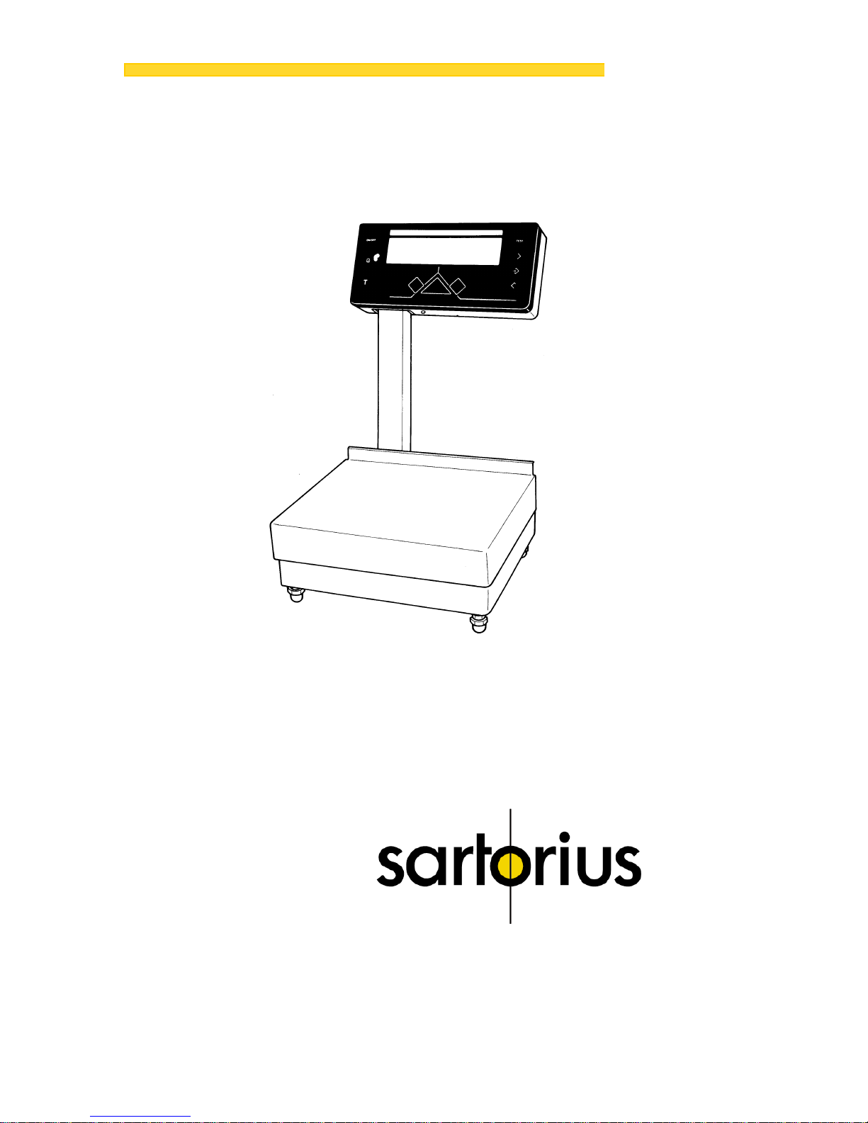
Sartorius
TS 6100B, TS 12
Electronic Over/Under Scales
Installation and Operating Instructions
98648-001-40
2
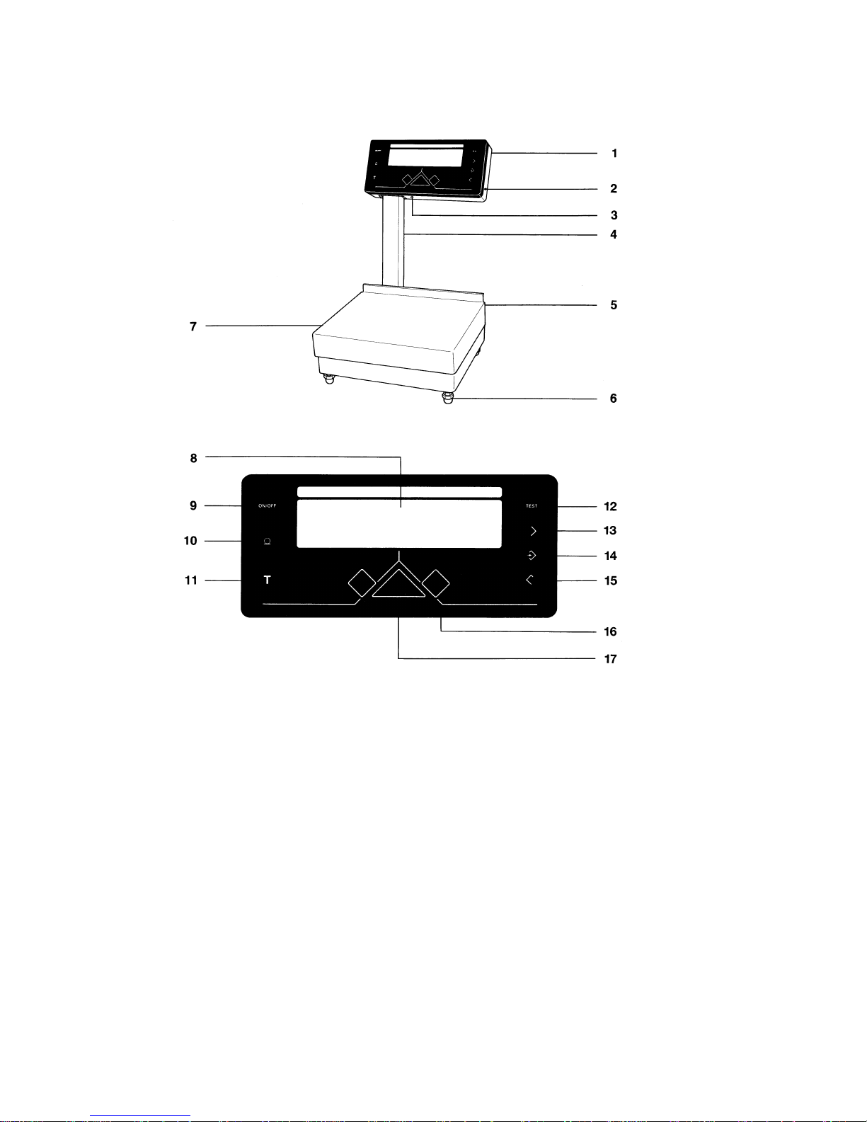
1
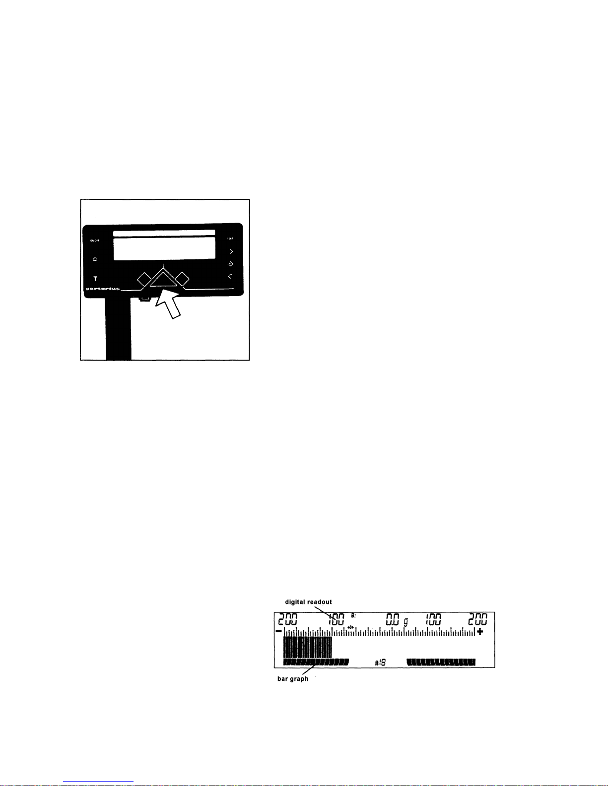
Display head
2
Lock
3
Jack for AC power
4
Support arm
5
Weighing platform
6
Leveling foot
7
Analog range indicator/weight display
8
ON/OFF key
9
PRINT key
10
Tare key (for zeroing the display)
11
Test key (full-segment display test)
12
Increase key
13
Set key
14
Decrease key
15
RED/GREEN/YELLOW indicators

3
Contents
Page
About the Product (Warranty)
4
Storage and Shipping Conditions 5
Equipment Supplied
6
Installation Instructions
6
Startup
7
Connecting the Scale to AC Power 7
Connecting Electronic Devices
(Peripherals) 8
Safety Precautions 8
How to Operate the Scale
9
Turning the Display On and Off 9
Taring 9
Weighing 9
Over/Under Checkweighing 11
Product ID Numbers and
Product Data
14
Changing the Product ID Number 15
Changing the Target Weight 16
Changing the Scale Divisions
in the Display 18
Changing the "Under" Limit 19
Changing the "Over" Limit 20
Calibration
21
Scale Operating Program
23
Factory Settings 24
How to Access the
Scale Operating Program 24
List of Parameters 26
Mounting Instructions
30
Changing the Display Mounting 30
How to Install the Interface Gable
Changing the Scale Housing Cover 31
Interface Description (Option)
32
General Specifications 32
Data Output Format 32
Data Output Parameters 33
Interfacing Devices with the Scale 33
Pin Assignment 34
Options and Accessories
35
Specifications
36
Troubleshooting Guide
37
Care and Maintenance
38
Cleaning 38
Safety Inspection 38

4
About the Product (Warranty)
With this Sartorius Scale you have acquired a high-quality
electronic weighing Instrument that will ease your daily
workload.
Please read these installation and operating instructions
carefully before operating your new scale.
Pursuant to the German Directive for the
Implementation of Regulations for Prevention of
Accidents "Elektrische Anlagen und
Betriebsmittel (VBG 4)" [Electrical Installations
and Equipment] of April 1986, it is hereby
certified that the equipment delivered, "Electronic
Over/Under Scale, model TS 6100B or TS 12," is
manufactured and tested in compliance with the
following DIN/VDE regulations:
DIN IEC 348/VDE 0411
Safety requirements for electronic measuring
apparatus
DIN IEC 380/VDE 0806
Safety of electrically energized Office machines
DIN IEC 601/VDE 0750
Safety of medical electrical equipment
and with Article 10 of the Low Voltage Directive
73/23/EEC issued on February 19, 1973, by the
European Community.
When you use electrical equipment in
installations and under ambient conditions
requiring higher safety Standards, you must
comply with the provisions as specified in the
applicable regulations for installation in your
country.

5
Do not miss out on the benefits of our full warranty.
Please complete the warranty registration card,
indicating the date of installation, and return the
card to your Sartorius dealer.
Storage and Shipping Conditions
Storage temperature: -40°C... +70°C
-40°F... 158°F
After unpacking the scale, please check it immediately for
any visible damage as a result of rough handling during
shipment.
lf this is the case, proceed as directed in the section
entitled "Safety Inspection."
Save all parts of the packaging and the box because
you may need to ship your scale.
Before you pack your scale to ship it, unplug all
connected cables to prevent damage.
Do not expose the scale unnecessarily to extreme temperatures, moisture, shocks, blows or vibrations.

6
Equipment Supplied
The equipment supplied includes the following components:
— Scale
— Weighing platform
— Power supply
— Key
— Set of brief instructions
— Instruction manual entitled "Installation and Oper-
ating Instructions"
Installations Instructions
Your Sartorius Scale will provide accurate readouts even
when it is exposed to unfavorable conditions.
However, exposure to intensive heat radiation, vibrations
and drafts may affect the weighing accuracy and should
be avoided äs much as possible.
You can adapt the scale to your requirements simply
by changing the menu code settings in the scale
operating program.
For more information, see pages 23 through 29.
7
Startup
Place the weighing platform
(5)
on the scale.
Connecting the Scale to AC Power
The scale is energized by an external power supply.
Make sure that the voltage rating printed on this unit is
identical to your local voltage rating.
lf the voltage specified on the label or the plug design of
the power supply does not match the rating or Standard
you use, please contact your Sartorius Office or dealer.
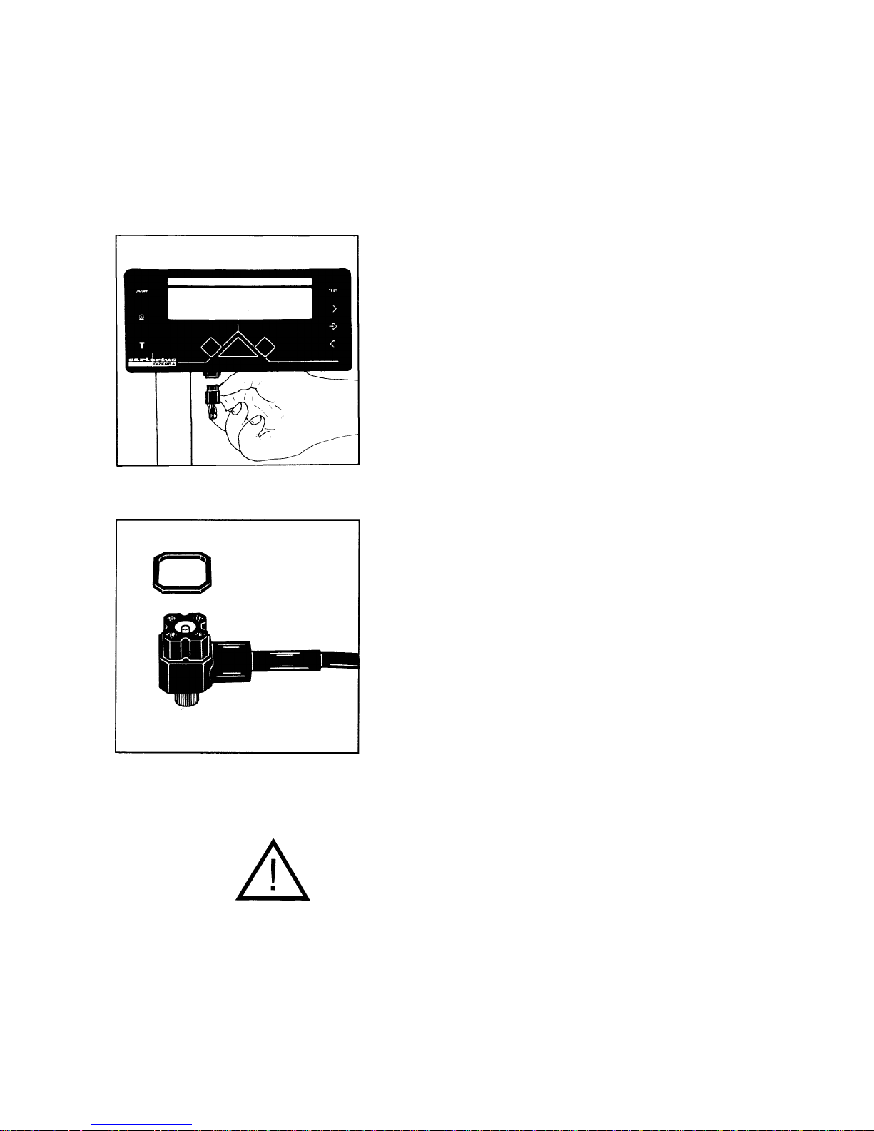
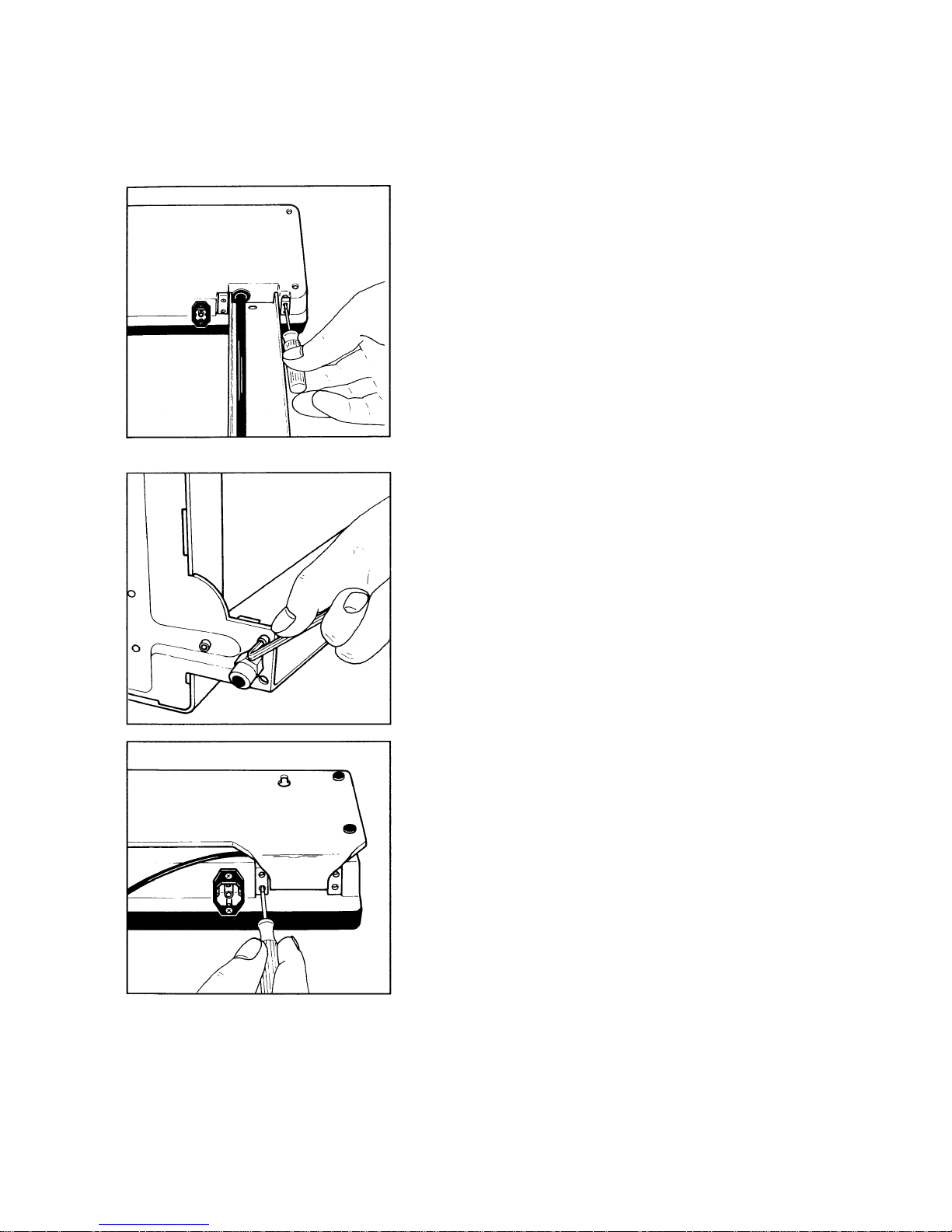
Insert the right-angle plug of the power supply in the AC
jack as shown in the picture on the left. Tighten the screw
by hand.
The IP 65 protection rating is guaranteed only if a
rubber gasket is instalied and the plug is securely
connected to form a leak-tight seal.
Then plug the power supply into a wall outlet.
Important Note:
Only use original Sartorius Power Supplies identified by
the Sartorius label. Use of power supplies from other
manufacturers, even if these units have a registered
approval rating from a national testing laboratory, requires
the consent of a certified Sartorius service technician.

8
Connecting Electronic Devices (Peripherals)
Make sure to unplug the power supply from the wall outlet
or from the scale before you connect or disconnect a
peripheral device (printer or PC) to or from the interface
port (Option).
Safety Precautions
The power supply rated to Class 2 (double insulation) can
be plugged into a wall outlet without taking any additional
safety precautions. The pole (ground) of the Output
voltage is connected to the scale housing (metallic parts),
which can be grounded for Operation.
The interface (see "Interfacing Devices" on page 33 in
addition) is also electrically connected to the scale housing (ground).

9
How to Operate the Scale
After initially connecting the scale to line power, allow
for at least 30 minutes' warmup.
Turning the Display On and Off
Press the ON/OFF key
(8)
to turn the display on or off.
Self-Test
After the scale is turned on, an automatic self-test of the
scale's electronic circuitry is performed. During this test,
all segments briefly appear in the display (full-segment
display test).
lt ends with the readout of all set parameters.
Taring
lf you wish to use a Container of if the weight display does
not indicate "
0.0 g/0 g
" (or the equivalent with the weight
unit of your choice), press the tare key before weighing.
10
The zero symbol (with arrows)
->0<-
in the weight display
shows that the scale has been exactly tared so the display
reads
"0"
.
Weighing
Place your sample on the weighing platform
(5)
to determine the weight.
Read off the weight indicated in the display
(7)
as soon as
the motion detection symbol "~" above the plus/minus
sign disappears.
In addition to grams, this scale gives you a variety of
other menu-definable weight unit options.
Select the weight unit you desire from the fable on
page 26 and change the code in the scale operating
program (for this purpose, see pages 23 through 29).
Auto Zero
This scale has an automatic zero tracking function, known
as "Auto Zero" (can be turned off by menu code - see
"Scale Operating Program").
Any changes off zero <± 0.5 digit per second will be set to
zero automatically.
11
Over/Under Checkweighing
Over/under checkweighing allows you to sort and classify
products according to preset limits.
"Classification" means sorting samples based on their
weight into classes with defined weight ranges.
RED/GREEN/YELLOW Indicators
The RED/GREEN/YELLOW indicators are convenient
visual aids.
When you weigh the object to be checked, one of these
color-coded indicators will light up to indicate the Status of
the sample as follows:
RED
= the sample is underweight
GREEN
= the sample is o.k. and within the
preselected tolerance range
Yellow
= the sample is overweight
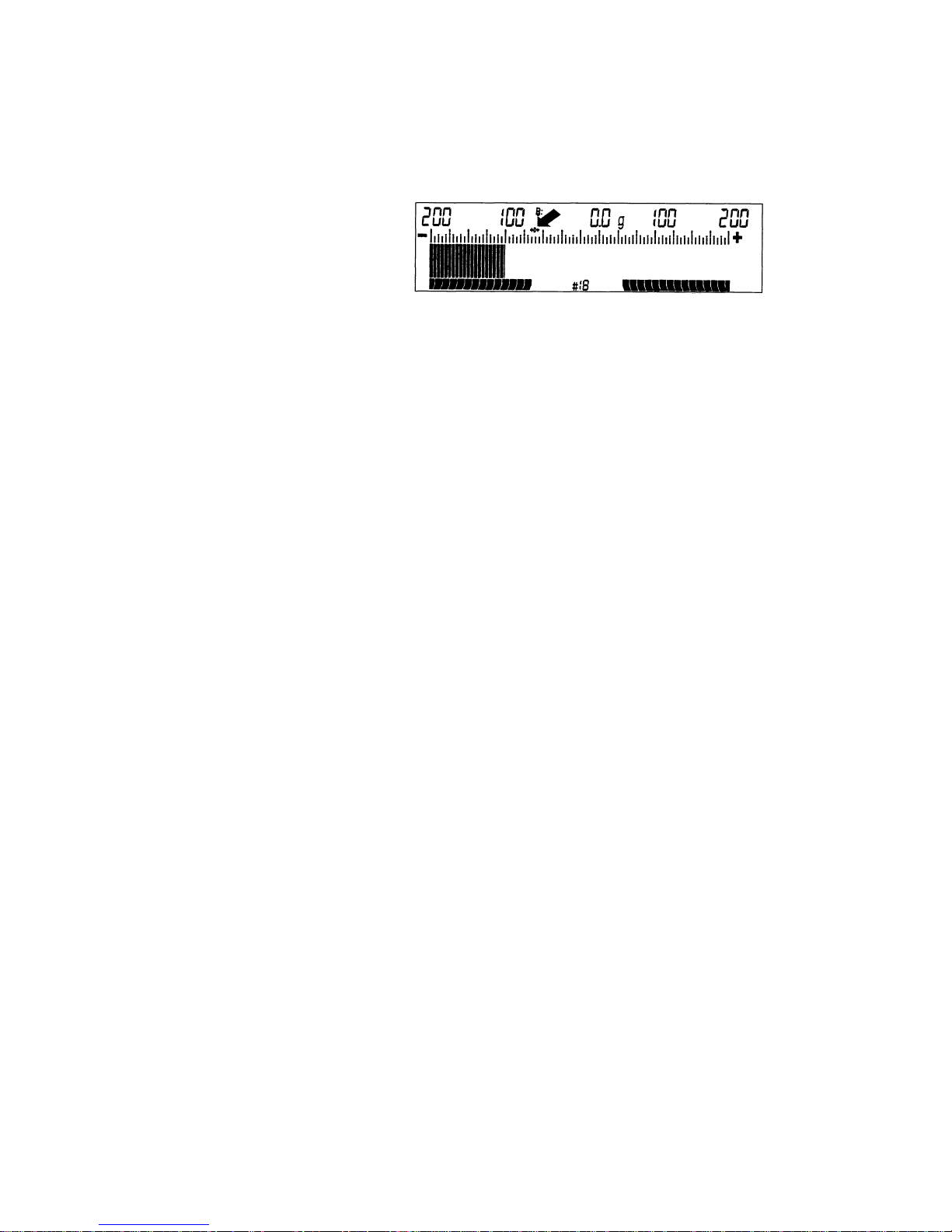
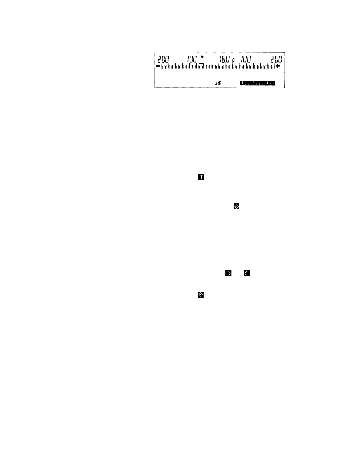
Wide Range Analog Indicator (Bar Graph)
At the same time, the wide range analog indicator, a bar
graph, gives you additional information on your sample.
The digital readout shows you the difference of the weight
of your sample from the target weight (depending on the
menu code set in the scale operating program) and the
bar graph helps you weigh-in accurately.
In addition, you can define the mode of this wide band
analog indicator to best meet your requirements.
12
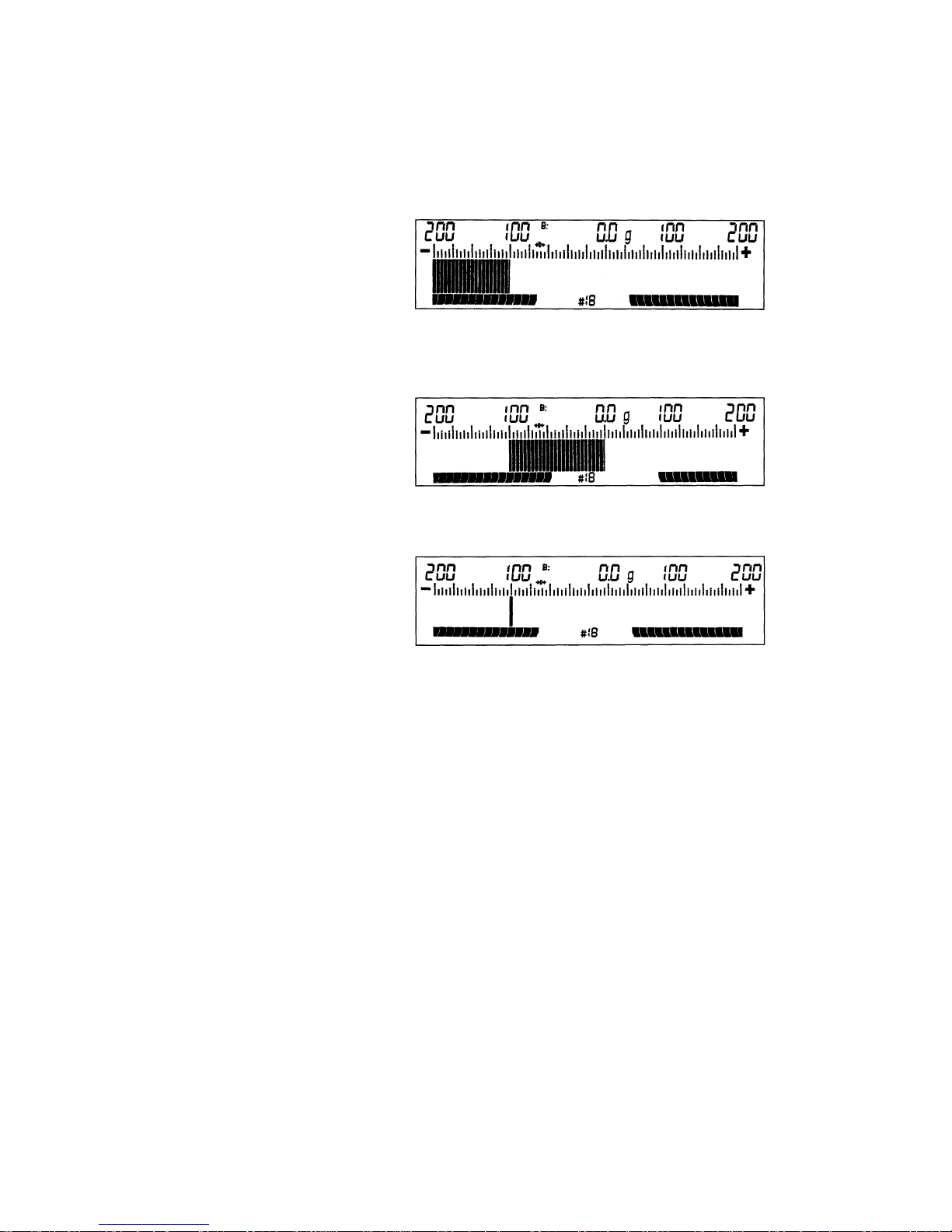
For example, for a target weight of 100 g, you can choose
between
— a continuous bar graph that travels from the left to the
right (for determination of a sample weight)
— a bar graph with a zero point = target weight
(for determination of the difference in weight)
— and a "traveling marker."
The bar graph mentioned above can be shown in the
following user-selectable application modes for the weight
display. Depending on your choice of the display mode,
set the appropriate menu code in the scale operating
program (see pages 23 through 29).
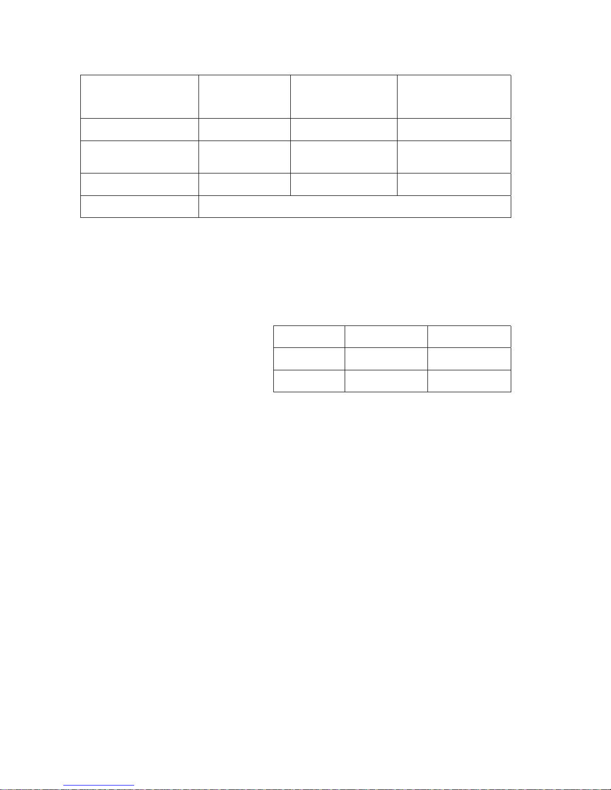
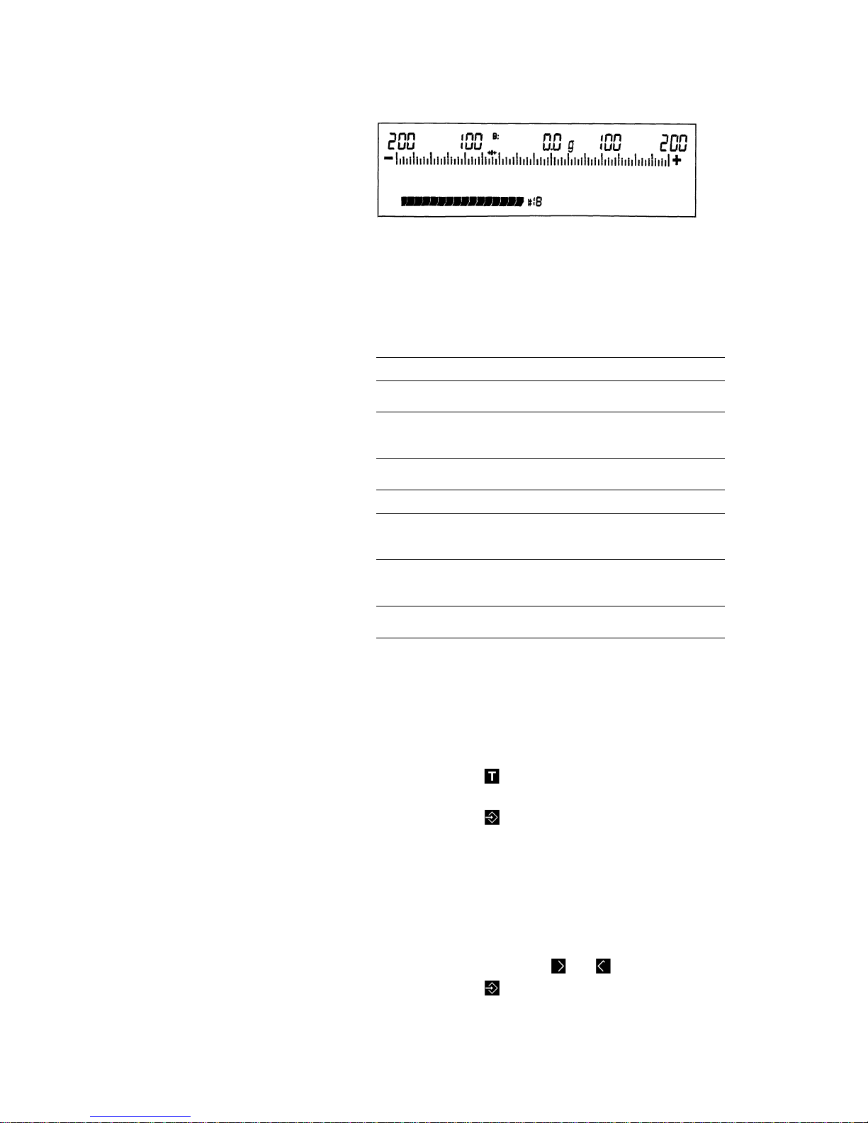
13
Without digital
weight readout
code:
3 2
With net weight
readout
code:
3 3
With readout of
the difference
in weight
code:
3 4
Continues bar graph
code:
9 6
X X X
Bar graph with
zero point = target weight
code:
9 7
X X X
Traveling marker
code:
9 5
X X X
No bar graph digital weight readout only
code:
3 1
The resolution of the display scale range depends on the
parameter you have selected.
Starting from the target weight, the over and under range
that can be displayed in either direction as follows:
Weight unit
in »g«
Weight unit
in »kg«
TS 6100 B
± 20 g, ± 40 g,
± 80 g, ± 200 g
± 400 g, ± 800 g,
± 2 kg
TS 12
± 40 g, ± 80 g,
± 200 g
± 400 g, ± 800 g,
± 2 kg, ± 4 kg

14
Product ID Numbers and
Product Data
Retrieving the desired Product ID Number
Press the
key
(8)
to turn the scale on.
The product ID number that is selected at the moment will
be displayed in the lower half of the weight display
(7)
.
To retrieve the desired product numbers, use keys
(12)
and
(14)
.
Changing Product Data
You can change and store the following for 12 different
products:
— the product ID number (1...12)
— the target weight
— the scale divisions in the display
— the lower and
— the upper tolerance limits.
These data are stored in a non-volatile memory so you do
not have to worry about a power outage.
The new product data are then available under the corresponding product ID numbers.

15
How to activate a product data function:
Press the
key
(8)
to turn the scale on.
Clear the weighing platform.
With the scale turned off, hold down the
key
(13)
and
briefly press the
key
(8)
.
When the readout is displayed, release the
key
(13)
.
Changing the Product ID Number
First select the product ID number you wish to assign to a
sample.
Caution:
Please keep in mind that all data stored under this ID
number will be deleted if you change the ID number.
The # symbol will flash in front of the product number
selected.
Use the
key to increase the number or the key to
decrease the number;
press the key labeled
to store the selected number.
The program will automatically change to the next parameter.

16
Changing the Target Weight
The target weight depends on the menu code setting in
the scale operating program.
You can enter the target weight either by storing the
weight of a sample on the platform or by numeric entry.
The following menu codes can be set in the scale operating program:
Code
1 1 1
Only target weight by loading sample; retain
same setting for over/under tolerance limits
1 1 2
Target weight by loading sample;
over/under limits by loading underweight and
overweight samples
1 1 3
Target weight by loading sample;over/under
limits by numeric entries using keys
1 1 4
Not assigned
1 1 5
Only target weight by numeric entry using
keys; retain same setting for over/under
tolerance limits
1 1 6
Target weight by numeric entry using keys;
over/under limits by loading underweight and
overweight samples
1 1 7
Target weight by numeric entry using keys;
over/under limits by numeric entries using keys
At the factory, we have set
code 1 1 3
.
lf necessary, you can change this setting. To do so,
please read pages 23 through 29.

17
How to enter a target weight using a sample on the
weighing platform:
— Clear the weighing platform
— Press the
key to tare the scale
— Place your sample on the platform (if you do not
place a sample on the weighing platform, the previous weight will be stored)
— Press the
key to store the weight.
Entering a numeric value for the target weight:
Five digits appear in the display - the last digit flashes.
— Press the
key to select the digit you wish to
change.
— Press the
key to change the flashing digit.
— To store the target weight you have entered,
press the
key. The program will automatically
change to the next parameter (scale divisions in
the display).
The error message "E3" will appear if:
—
the value of the target weight is negative, or
—
the value entered is too large.

18
Changing the Scale Divisions in the Display
lf you do not wish to change the tolerance limits, it is not
necessary to change the scale divisions
(codes 1 1 5, 1 1 1). In this case, the scale will skip the
following steps.
The user-definable scale divisions in the display allow you
to spot off-weights easily.
Depending on the expected off-weights of the samples to
be checkweighed, you can expand the analog display by
selecting a lower number of the scale divisions.
Possible settings:
Weight unit
in »g±
Weight unit
in »kg±
TS 6100 B
± 20 g, ± 40 g,
± 80 g, ± 200 g
± 400 g, ± 800 g,
± 2 kg
TS 12
± 40 g, ± 80 g,
± 200 g
± 400 g, ± 800 g,
± 2 kg, ± 4 k g
Press the keys labeled
or each time to increase or
decrease the scale division settings.
To store a setting, press the key labeled
; the program
will automatically change to the next parameter (tolerance
limits).
19
Changing the "Under" Limit
Depending on the menu code setting in the scale operating program, you can enter the under limit either by storing the weight of a sample on the platform or by numerical
entry.
The following menu codes can be set in the scale operating program:
Code
1 1 1
Target weight by loading sample; retain same
setting for over/under tolerance limits
1 1 2
Target weight by loading sample;
over/under limits by loading underweight and
overweight samples
1 1 3
Target weight by loading sample; over/under
limits by numeric entries using keys
1 1 4
Not assigned
1 1 5
Target weight by numeric entry using keys;
retain same setting for over/under tolerance
limits
1 1 6
Target weight by numeric entry using keys;
over/under limits by loading underweight and
overweight samples
1 1 7
Target weight by numeric entry using keys;
over/under limits by numeric entries using keys
How to enter the under limit using an
underweight sample:
— Clear the weighing platform
— Press the
key to tare the scale
— Place the sample on the platform and
— Press the
key to store the weight.
How to enter a numeric value for the under limit:
The analog range for the under limit will flash.
Starting with the limit previously set, enter the "under" limit
as a deviation from the target weight.
— Use the keys labeled
and to enter the limit.
— Press the
key to store the numeric underweight you have just entered; the program will
automatically change to the next parameter.
20
Changing the “Over” Limit
Depending on the menu code setting in the scale operating program, you can enter the over limit in one of two
ways: either by storing the weight of a sample on the
platform or by a numeric entry (see "Changing the Under
Limit").
How to enter an over limit using an overweight sample:
— Clear the weighing platform
— Press the
key to tare the scale
— Place your sample on the platform (at this point,
load the target weight and the tolerance weight to
obtain an overweight sample) and
— store the weight with the
key.
How to enter a numeric value for an over limit:
The analog range for the over limit will flash.
Starting with the limit previously set, enter the over limit as
a deviation from the target weight.
— Use the keys labeled
and to change the
value.
— To store the "over" weight you have just entered,
press the
key.
This completes the entry of product data; the program will
automatically change to the weighing mode.

21
Calibration
This is only possible with an accurate calibration weight:
(see "Accessories")
Model Calibration weight Order number
TS 6100 B 5000 g 707213
TS 12 10000 g 707218
How to activate the calibration function:
Insert the
in the side of the display head.
Unload the weighing platform.
With the scale turned off, hold down the
key and
briefly press the
key
(8)
.
Once the readout appears, release the
key.
lf
->0<-
does not appear below "DEF," tare the scale.

22
Then press the
key - the calibration weight will appear,
i.e.:
Center the calibration weight on the weighing platform.
lf "+" appears in front of the weight readout, the calibration
weight is too light. lf "–" is displayed, the weight is too
heavy.
The plus/minus sign disappears if the calibration weight is
accepted and an acoustic Signal indicates the end of the
calibration procedure.
The "+" symbol reappears at this time, also.
23
Scale Operating Program
In order to access the scale operating program, you will
need the
.
The scale operating program enables you to change the
menu code settings for the weight unit, the individual
operating parameters for the scale, the display mode,
Update rate and the data output parameter, including the
parameter for the application mode.
At the factory, we have set the codes for the scale operating program so you do not need to make any changes if
you only want to use the "over/under check weighing"
mode under normal ambient conditions.
Any changes to the menu codes in the scale operating program will affect how the products are weighed.
To familiarize yourself with all of the performance capabilities this scale offers, why not try out a few menu code
settings that sound interesting to you?
After all, you can always change them back to the original
settings.
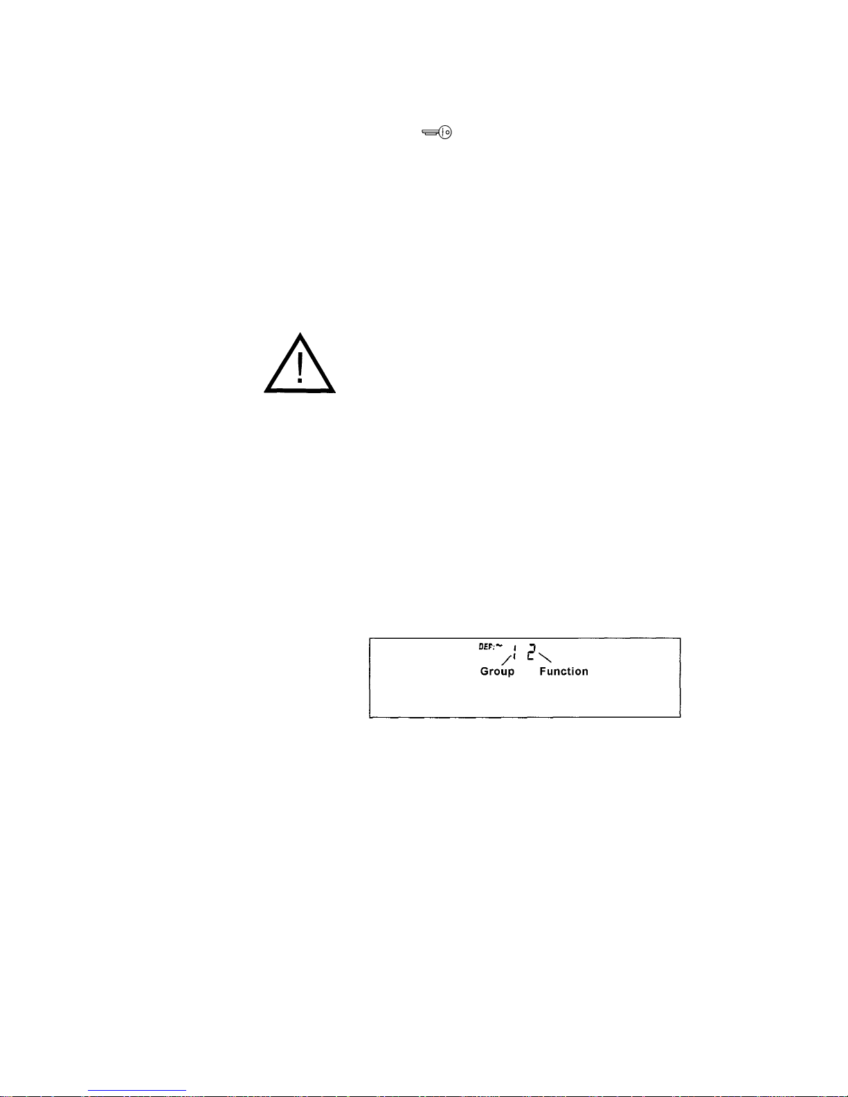
Use the "
codes
" to select the desired function in the
menu of the scale operating program.
Each code consists of a left-hand number for the function
group and a right-hand number for a function within a
group.

24
Factory Settings
Code
1 — 1 7 — 2
2 — 2 8 — 2
3 — 3 9 — 14
4 — 1 10 — 1
5 — 5 11 — 3
6 — 2 12 — 2
How to Access the Scale Operating Program
Insert the
in the lock located on the side of the
display head.
With the scale turned off, hold down the
key and briefly
press the
key
(8)
.

25
After the readout appears, release the
key.
To check a menu code setting, select the desired function
group using the
or key.
Press the
key to access a particular function.
Now the numeric code for the function will be displayed.
The function setting is identified by the symbol "~" that
appears after "
DEF
."
Use the keys labeled
and to select the desired
function.
Use the
key to confirm the setting; the code will then
disappear.
Now you can select the next function group.
Remove the key after you have finished entering the
desired codes and
only a function group
is displayed.
By doing so, you will leave the scale operating program
and the code changes will be saved at the same time.
lf you turn off the scale using the ON/OFF key while
the scale operating program is accessed, none of the
code changes will be stored.
The following pages will give you a list of the functions in
the scale operating program.
26
List of the Programmable menu Code Settings
“*” = Factory setting
Code Weight units
1 1* Grams g
1 2 Kilograms kg
1 3 Pounds lb
1 4 Ounces oz
1 5 Troy ounces ozt
1 6 grams
«0»
lf you change between grams and kilograms, the product weights
stored will remain valid, but not if you change the code to other weight units.
Code Acoustic Signal
2 1 Off
2 2* On
Code Application Mode for Weight Display
3 1 Digital weight readout only (weighing mode)
3 2 Over/under application without digital weight readout
3 3* Over/under application with net weight readout
3 4 Over/under application with readout of the difference in weight
(weight displayed = difference from the target weight)
Code Ambient Conditions
4 1* Stable (100 ms display update)
4 2 Stable to unstable (200 ms display update)

27
Code Stability Range
5 1 0,25 digit
5 2 0,5 digit
5 3 1 digit
5 4 2 digits
5 5* 4 digits
5 6 8 digits
5 7 16 digits
5 8 32 digits
The motion detection symbol "~" will appear only if a change in weight beyond the
defined number of digits is detected.
Code Tare Parameter (Zeroing the Display)
6 1 Without stability control
(the tare command is immediately executed)
6 2* At stability
(the tare command is stored until the scale has stabilized and is then executed)
Code Auto-Zero
7 1 Off
7 2* On
The scale features an automatic zero tracking function, known as "Auto Zero.
When this function is on, changes off zero ≤ 0.5 of a digit per second are set to zero
automatically after the display is zeroed with the tare key.

28
Code Data Output Parameter Printout
8 1 Single print when key is pressed, regardless of stability Actual weight
8 2* Single print when key is pressed and readout is stable Actual weight
8 3 Single print when key is pressed and weight readout is
stable & within the display range
Actual weight
8 4 Auto print regardless of stability Actual weight
8 5 Auto print when readout is stable Actual weight
8 6 Auto print when the weight readout is in the display
scale range and stable
Actual weight
8 7 Single print activated by load when readout is stable Actual weight
8 8 Single print activated by load when readout is stable and
within the display scale range
Actual weight
8 9 Single print when key is pressed, regardless of stability Weight difference
8 10 Single print when key is pressed and readout is stable Weight difference
8 11 Single print when key is pressed and readout is
stable & within the display scale range
Weight difference
8 12 Auto print regardless of stability Weight difference
8 13 Auto print when readout is stable Weight difference
8 14 Auto print when readout is stable and within display
scale range
Weight difference
8 15 Single print activated by load when readout is stable Weight difference
8 16 Single print activated by load when readout is
stable & within the display scale range
Weight difference
Single print = Output of an individual weight
Auto print = Automatic, continuous output of weights
(can be stopped and started by pressing the print key)
Stability; stable = The motion detection symbol is not displayed
Display scale range = Analog display of the weighing range with user-definable
scale divisions
Activated by load = An individual value is output automatically when a load is on
the platform and the scale has stabilized.
This procedure may be repeated once the weight is removed from the platform.

29
Code Analog Display/Backlighting
9 1 Marker Backlighting off
9 2 Bar graph for sample weight Backlighting off
9 3 Bar graph for weight difference Backlighting off
9 4 Not assigned
9 5 Marker Backlighting on
9 6 Bar graph for sample weight Backlighting on
9 7 Bar graph for weight difference Backlighting on
9 8 Not assigned
9 9 Marker Backlighting off, LED on
9 10 Bar graph for sample weight Backlighting off, LED on
9 11 Bar graph for weight difference Backlighting off, LED on
9 12 Not assigned
9 13 Marker Backlighting on
9 14* Bar graph for sample weight Backlighting on, LED on
9 15 Bar graph for weight difference Backlighting on, LED on
Code Product Selection Mode
10 1* Only with inserted key
10 2 Without key
Code Entry Mode for the Target Weight and Limits
11 1 Target weight by loading sample; retain same setting
for over/under tolerance limits
11 2 Target weight by loading sample; over/under limits by loading underweight
and overweight samples
11 3* Target weight by loading sample; over/under limits by numeric
entries using keys
11 4 Not assigned
11 5 Target weight by numeric entry using keys; retain same setting for
over/under tolerance limits
11 6 Target weight by numeric entry using keys; over/under limits by loading
underweight and overweight samples
11 7 Target weight by numeric entry using keys; over/under limits by numeric
entries using keys
Code RED/GREEN/YELLOW Indicators
12 1
"RED" off when load approx. <5% of the target weight,
weight readout at stability
12 2*
"RED" on when load approx. <5% of the target weight,
weight readout regardless of stability
12 3
"RED" off when load approx. <5% of the target weight,
weight readout at stability
12 4
"RED" on when load approx. <5% of the target weight, LED only when readout
weight readout at stability is stable
30
Mounting Instructions
Changing the Display Mounting
(Raised Display to Remote Display)
— Loosen the cable clamp on the support arm
— Remove the retainer bars for the support arm
from the display head
— Dismount the display head
— Remove the three screws from the support arm
base plate
— Dismount the support arm
— Use the retainer bars to fasten the holder to the
display head
How to Install the Interface Cable
The interface cable should be installed only by a
certified electrician.
Ask for separate instructions describing how to install the
interface cable.

31
Changing the Scale Housing Cover
— Remove the weighing platform
— Unscrew the 4 platform support disks
— Gently pull the left and right sides of the scale
housing cover outward and lift it off
— Place a new housing cover on the scale base,
making sure that both sides snap in audibly
— Refasten the four platform support disks
using the screws
— Reposition the weighing platform
32
Interface Description (Option)
lf you wish to record weight data using the Sartorius Data Printer, just plug the printer
connector Mo the interface port of the scale. You do not need to adjust any settings!
(You can also interface your scale with a Computer.)
General Specifications
Type of interface Serial point-to-point connector
Operating mode Asynchronous, simplex
Standard V24-V28, RS232 C-S
Handshake lines Clear to Send (CTS)
Data Terminal Ready (DTR)
Initialization External or automatic print command depending
of the interface on the code selected (8 1 to 8 16)
Character coding 7-bit ASCII
Transmission rate 1,200 baud
Parity Odd
Synchronization 1 Start bit, 1 stop bit
Additional port lines for 4, for upper/lower limits,
over/under checkweighing tolerance range and target
Data Output Format
1 2 3 4 5 6 7 8 9 10 11 12 13 14 15 16 17 18 19 20 21 22
H H - - - -
+
-
- - Z Z Z Z Z Z Z _ X X X CR LF
1st and 2nd characters: Weight difference or net weight
3rd to 6th characters: Space
7th character: Plus or minus signor space
8th and 9th characters: Space
10th to 16th characters: Digit, space or decimal point
17th character: Space
18th to 20th characters: Letter or space
21st character: Carriage Return
22nd character: Line Feed

33
Data Output Parameters
(Codes
8 1
to
8 16
)
Data can be transferred to the output port depending on
the particular stability state of the weighing system (stability parameter: stable readouts).
You can choose to have data transferred regardless of
stability or only when the readout is stable.
lf you opt to have data transferred only when the weighing
system has stabilized, an output command will remain
stored until the system has stabilized.
For the auto print setting (automatic data output), weight
data are transferred continuously the moment you turn on
the power. lf you have additionally selected the stability
parameter for this Option, only data for stable readouts
will be output. To stop and start automatic data transfer,
press the print key.
Each signal received by the RxD line will initiate data
transfer (external data request).
Interfacing Devices with the Scale (RS Interface)
Make sure that the interface port is electrically connected
to the scale housing. The interface cable supplied as an
optional accessory is shielded and must be installed so
that the interface end is electrically connected to the
housing. This electrical connection may result in interference caused by ground loops or by transient currents if
you have grounded the housing or connected the protective grounding conductor for AC power. lf necessary,
connect an equipotential bonding conductor to the scale.

34
Pin Assignment for the Interface
Female Interface Connector:
25-position D-submini DB25S with screw lock hardware for the cable gland
Male Connector Required:
25-pin D-submini DB25S with integrated shielded cable clamp assembly (Amp type 826 982-1) and
fastening screws (male screws for female screw lock, Amp type 164 868-1)
Pin Assignment
Designations Direction Standard Level
Pin 1: Protective Ground
Pin 2: Data Output (TxD) Output RS323
Pin 3: Data lnput (RxD) lnput RS232
Pin 4: Not Connected
Pin 5: Clear to Send (CTS) lnput RS232
Pin 6: Not Connected
Pin 7: Internal Ground
Pin 8: Internal Ground
Pin 9: Not Connected
Pin 10: Not Connected Print/Tare*)
Pin 11: +12 V Output (50 mA max.)
Pin 12: Reset —| Output TTL
Pin 13: +5 V Output (50 mA max.)
Pin 14: Internal Ground
Pin 15: lnput open Collector
Pin 16: Low Signal Output LS-TTL
Pin 17: OK Signal Output LS-TTL
Pin 18: High Signal Output LS-TTL
Pin 19: Set Signal Output LS-TTL
Pin 20: Data Terminal Ready (DTR) Output RS232
Pin 21: Not Connected
Pin 22: Not Connected
Pin 23: Not Connected
Pin 24: Not Connected
Pin 25: +5 V Output (50 mA max.)
*) Print or tare (have this parameter implemented or changed by a Sartorius service technician)

35
Options and Accessories
Options
Interface
YDO 01 TS
(for connecting a data printer or a PC)
Display holder
YDH 01 TS
for benchtop or wall mounting
Spacer feet
YAS 01 TS- 00
for lifting the scale by about 8 cm (3") 000 V 001
Spare scale housing cover 69 T 00001
Accessories
Data printer
with date/time YDP 02-0DV1
& statistics functions
Print speed approx. lines/sec. 1.5
Printer housing (W x D x H)
in mm 150x138x43
in inches 5.9x5.4x1.7
Calibration weight
for TS 6100 B 707213
Calibration weight
for TS 12 707218

36
Specifications
Model
TS 6100B TS 12
Capacity g 6,100 12,100
Readability g 0.5 1
Tare range (by subtraction) g -6,100 -12,100
Standard deviation g
≤ ± 0.5 ≤ ± 1
Max. linearity g
≤ ± 0.5 ≤ ± 1
Stabilization time (typical) s 1.1
Display Update
– when the readout stabilizes
(depends on the filter level
selected)
– when the load changes
s
s
0.1/0.2
0.1
Adaptation to application requirements
and ambient conditions
By selection of one of 2 optimized filter levels
Stability range d 0.25 ... 32 (selectable)
Ambient temperature range K 273 — 313 (0oC...+40oC) (32oF … 104oF)
Moisture-proof rating acc. to DIN 40040 Class F, non-condensing
Dust and water protection rating in
conformance with DIN 40050/IEC529
IP65
Sensitivity drift within 10...30°C /oC
≤±2.5 ∙ 10
-6
Platform size
mm
in.
260 x 210
10.2 x 8.4
Scale housing (W x D x H)
mm
in.
260 x 295 x 110/450
10.2 x 11.6 x 4.3/17.7
Net weight, approx.
kg
~lb
6.5
14.3
Power requirements
(voltage + frequency)
115 or 230 depending on the type
of power supply used; 50-60 Hz
Allowable voltage fluctuation -20% ... +15%
Power consumption (typ.) VA 14

37
Troubleshooting Guide
Problem … Causes … Solution
No segments appear in the weight
display
(7)
- No AC power available
- The power supply is not plugged
in
- Check AC power supply
- Plug in power supply
Display shows
“L”
- The weighing platform
(5)
is not in
place
- Position the platform
Display shows
“H”
- The load exceeds the capacity of
the scale
- Unload the scale
The weight readout changes
constantly
- Unstable ambient conditions
- Too much Vibration or the scale is
exposed to a draft
- Set up the scale in another area
- Access the menu to select the
proper code for the particular type
of weighing environment
Display shows
“EO”
- The platform was not empty
during calibration
- Clear weighing platform and
repeat calibration procedure
The weight readout is obviously
wrong
- The scale has not been calibrated
- The scale has not been tared
before weighing
- Calibrate the scale
- Tare before weighing

38
Care and Maintenance
Clearing
Wash down the scale with cleaning agents that you
commonly use in the food industry.
Important Note:
Featuring the IP 65 protection rating (approximately
equivalent to NEMA 4), the scale is dust-tight and
washdown-resistant. See the "Test Mark Award Certificate" issued by the TÜV, the German Association
for Technical Inspection.
Safety Inspection
lf there is any indication that safe Operation of the scale
with the power supply is no longer warranted, turn off the
power and unplug the scale from the power supply immediately. Lock the scale in a secure place to ensure that it
cannot be used for the time being.
In this case, notify your nearest Sartorius Service Center
or the International Technical Support Group based in
Goettingen, Germany. Only Sartorius service technicians
who are authorized by Sartorius and have the proper
manuals are allowed to perform maintenance and repair
work on the scale.
Safe Operation of the scale with the power supply is no
longer ensured when
— there is visible damage to the power supply
— the power supply no longer functions properly
We recommend that the scale and power supply be
inspected according to the following checklist by a qualified Sartorius service technician:
— Leakage current <0.05 mA measured by a prop-
erly calibrated multimeter
— Insulation resistance >7 megohms measured with
a constant voltage of at least 500 V at a 500
kohm load.
The duration and number of measurements should be
determined by a qualified Sartorius service technician
according to the particular ambient and operational conditions. However, such inspection should be done at least
once a year.


Sartorius AG
B 37070 Göttingen
P Weender Landstraße 94–108, 37075 Göttingen
T (0551) 308-0, F (0551) 308-3289
Internet: http://www.sartorius.com
Copyright by Sartorius AG, Göttingen, Deutschland.
All rights reserved. No part of this publication may be
printed or translated in any form or by any means without
the prior written permission of Sartorius AG.
Sartorius AG reserves the right to make change to the
technology, features, specification and design of the equipment
without notice.
 Loading...