

Sartorius Sterisart Universal Pump 16420 Operating Instructions Manual

Operating Instructions | Betriebsanleitung
Sterisart Universal Pump 16420
Sterisart
®
Universal-Pumpe 16420
85030-531-20

Auf der beiliegenden CD befindet sich die Bedienungsanleitung
für Sterisart® Universal-Pumpe 16420 als PDF-File in französischer,
italienischer und spanischer Sprache.
Sollte die CD fehlen können Sie diese unter Angabe
der Bestellnummer bei uns beziehen:
Bestellnummer: 85032-537-64
Publikationsnummer: SLD6026-l
Sartorius Stedim Biotech GmbH
Technical Editorial Department
August-Spindler-Strasse 11
37079 Goettingen, Germany
www.sartorius-stedim.com
Systemvoraussetzungen:
Windows® XP oder höher
Adobe® Reader® 5.0 oder höher
The enclosed CD contains the operating instructions
for Sterisart Universal Pump 16420 as a PDF file in
French, Italian and Spanish.
If the CD is missing, you can obtain a copy form us by
specifying the order number:
Order number: 85032-537-64
Publication number: SLD6026-l
Sartorius Stedim Biotech GmbH
Technical Editorial Department
August-Spindler-Strasse 11
37079 Goettingen, Germany
www.sartorius-stedim.com
System requirements:
Windows® XP or higher
Adobe® Reader® 5.0 or higher

Contents 3
English ................................................ Page 3
Deutsch ............................................... Seite 35
Contents
Manufacturer|Distributor........................4
EC Declaration of Conformity .....................4
General Safety Information.......................5
1 Intended Use of the Sterisart Universal Pump .....7
2 Important Notes on the Safe and
Proper Usage of the Sterisart Universal Pump .....7
3 Unpacking the Pump and Checking the
Equipment Supplied . . . . . . . . . . . . . . . . . . . . . . . . . . . . 8
4 Description of the Sterisart Universal Pump .......9
5 Startup ......................................11
6 Application...................................13
6.1 Operating the Sterisart Universal Pump 16420...14
7 Configuring the Sterisart Pump.................18
8 Emergency Operation Mode ....................24
9 Maintenance .................................24
10 Cleaning and Sanitization ......................25
11 Installation in an Isolator ......................27
12 Important Notes Concerning the Warranty.......27
13 Troubleshooting...............................28
14 Technical Specifications........................29
15 Ordering Information for the
Sterisart Universal Pump .......................30
16 Ordering Information for Consumables ..........31
17 Literature ....................................32
18 Information and Instructions on Disposal ........32
Non-hazardous Declaration......................33

Manufacturer|Distributor
Manufacturer: Möller Medical GmbH
Wasserkuppenstr. 29-31
D-36043 Fulda, Germany
Distributor: Sartorius Stedim Biotech GmbH
August-Spindler-Strasse 11
D-37079 Goettingen, Germany
Tel.: +49.551.308.0
Fax. +49.551.308.3289
www.sartorius-stedim.com
EC Declaration of Conformity
We hereby declare that the Sterisart Universal pump 16420 has been designed
and manufactured according to the following directives:
2006/95/EC – Low voltage
2006/42/EC – Machinery
2004/108/EC – Electromagnetic compatibility
2002/95/EC – RoHS Directive
The Sterisart Universal pump 16420 is labeled with the CE mark.
4 Manufacturer|Distributor
General Safety Information 5
General Safety Information
Explanation of Safety Symbols Used
These operating instructions contain important information which is visibly marked.
This information must be observed in order to avoid hazards to users as well as to
avoid damage and|or malfunctions to the device.
Symbols in the operating instructions:
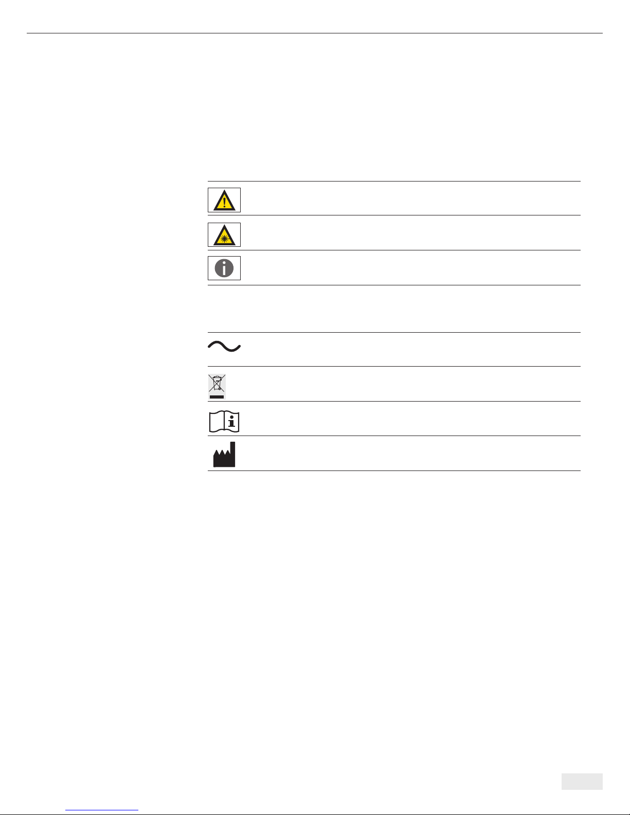
Important Note! Important information
Danger! General danger with risk of injury
Laser warning
General information and| or help
Symbols on the manufacturer‘s ID label
AC voltage
Return and disposal
Observe instructions for use
Manufacturer

6

1 Intended Use of the
Sterisart Universal Pump
The new Sterisart Universal pump is a peristaltic pump equipped with appropriate
devices for attaching a closed sterility test system and a sample container.
The pump draws liquid from the sample container into the specially designed double
tubing, distributing the liquid equally to both sample containers of the sterility test
system. The sample is rinsed in a similar way. After the nutrient media is added, the
sample containers are incubated for a prescribed time and evaluated.
2 Important Notes on the Safe
and Proper Usage of the Sterisart
Universal Pump
– The Sterisart Universal pump must be switched off before any electrical connections
are made or broken (e.g. when plugging in or unplugging the power cable, foot
switch or control unit with display).
– The Sterisart Universal pump must only be used with the original current-carrying
parts supplied with it (power cable with ferrite core, D-Sub connecting cable and
foot switch). The D-Sub protective cap supplied must cover the port when the
D-Sub connecting cable is not connected.
– The Sterisart Universal pump is designed for use with Sterisart NF filtration systems.
The suitability of any other tubing must be approved by Sartorius.
– Only authorized Sartorius service technicians are allowed to open the pump
housing.
– Do not expose the Sterisart Universal pump to extreme temperatures.
– Improper use or handling will invalidate the manufacturer‘s guarantee.
– Sterisart Universal pump may only be used with a grounded, readily accessible
and fuse-protected electrical outlet that complies with national standards.
– When using device components that do not correspond to their original version,
performance, safety and EMC behavior can be negatively affected.
Intended Use of the Sterisart Universal Pump | Important Notes on the Safe and Proper Usage of the Sterisart Universal Pump 7

3 Unpacking the Pump and Checking
the Equipment Supplied
When unpacking the Sterisart Universal pump 16420 make sure not to leave any
parts in the packaging. The equipment supplied includes the following accessories
(1 piece each):
– Sterisart Universal pump 16420
– Control unit
– Clamp for control unit
– Power cable (country-specific)
– Draining container
– Draining container cover (Sterisart units)
– Drain tubing
– Fastening arm
– Holding ring for bottles
– Support rod
– Bow
– Clamping lever with sleeve
– Operating instructions in German|English
8 Unpacking the Pump and Checking the Equipment Supplied

Description of the Sterisart Universal Pump 9
4 Description of the Sterisart
Universal Pump
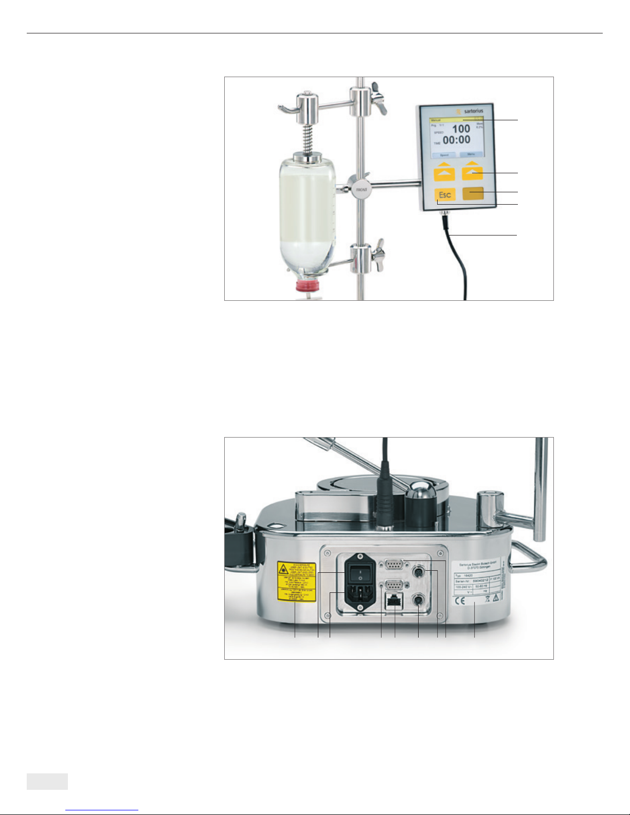
Fig. 1
The Sterisart Universal pump (Model 16420, see Fig. 1) consists of pump housing (1)
with pump head (2), lever (3), bow (4) and handles (5). On the right handle, there is
also a bolt with a tilting lock for the draining container (14). The selecting knob (6)
is located on the front right. The stand (7), including holding ring for bottles (8),
fastening arm (9) and optional ampoule breaker (10), is located on the left side of the
pump. Additionally, the control unit (11) is also fastened to the stand via the control
unit clamp (12) and connected to the pump via the connecting cable plug (13)
(see Fig. 1).
Laser warning
The internal barcode scanner emits a laser beam.
Do not look directly into the beam.
2
1
4
14
15
5
6
7
9
10
8
3
11
12
13
a
b
d
c
e
8 1 2 5 7 6 3 4 9
Fig. 2
The display and control unit consists of (Fig. 2): glass display (a), 2 soft keys (b),
1 Esc key (c), window for barcode scanner (d), pump connecting cable with plug (e).
The draining container (Fig. 1; 14) for the sterility test containers is fastened to the
right of the pump. Here, a draining tube can be connected to the designated flange
connection (Fig. 1; 15).
Fig. 3
Located on the rear panel (see Figure 3): On|Off switch (1), AC power socket (2),
socket for the foot switch (3), an RS-232 interface port for connecting a PC/MMC
card reader (4), an RS-232 interface port for connecting an external barcode scanner
(5), the syringe actuator (6, optional), the RS-485 port (7), a laser warning label (8)
and the manufacturer’s ID label (9).
10 Description of the Sterisart Universal Pump
5 Startup
Set up the Sterisart universal pump ergonomically in a suitable area (cleanroom,
laminar flow work bench, isolator).
Before initial start-up, the accessories supplied must be assembled on the Sterisart
Universal pump. Please proceed in the following order:
At the back left, push the stand (Fig. 1, 7) onto the pins of the upper part of the pump
until it is firmly in place. The holes in the foot of the stand can be used to change the
position of the stand.
– First, fasten the holding ring for bottles to the stand (Fig. 1, 8), next fasten the con-
trol unit clamp (Fig. 1, 12) with the display and control unit (Fig. 1, 11; only for version 16420) and the fastening arm (Fig. 1, 9). Then make the electrical connection
to the pump via the control unit‘s cable and plug contact (Fig. 1, 13). If necessary,
attach the ampoule breaker (Fig. 1, 10) beforehand.
– Insert the bow (Fig. 1, 4) and the clamping lever (Fig. 1, 3) on the corresponding
bolts on the top of the pump. The lever is jacketed in a plastic sleeve that can be
removed for cleaning. If signs of wear appear on this sleeve after it has been in use
for some time, it can be re-ordered as a spare part (see Chapter 14).
– After attaching the drain tubing to the flange connection (Fig. 1, 15) on the drain-
ing container (Fig. 1, 14), attach the draining container to the appropriate bolt
with tilting lock on the right handle (Fig. 1, 5). The draining container and the
cover plate are attached by moving the tilting lock.
– Fasten the end of the drain tubing to the appropriate drain.
Very Important Note!
Always make sure that there is a sufficient liquid level differential (> 5 cm)
between the draining container and the drain. This makes safe drainage possible
and prevents backflow into the draining container. Make sure that the drain
tubing is kept lower than the pump to prevent the drain pan from overflowing.
Treat the waste as a biohazard. Only dispose of it in accordance with current
regulations.
Startup 11

– Plug the optional foot switch into the designated socket located on the rear panel.
(see Fig 3, 3). Fasten the plug to the socket by turning it clockwise.
– Plug the power cable into the male power socket on the back of the Sterisart
Universal pump and into a grounded electrical outlet (Fig. 3, 2).
– Use the On|Off switch (Fig. 3, 1) at the front of the Sterisart Universal pump
to turn it on.
After connecting the power, a boot sequence will appear for 6 seconds with relevant
information (Fig. 4). This displays the current software version of the main board
(main firmware), the software version of the display and control unit (UI firmware)
as well as the device bus address (Fig. 4).
During startup, the control unit carries out a self test whereby the internal barcode
scanner is turned on for a brief time.
After a successful switch-on test, the system is factory set to switch into the manual
operating mode (see Fig. 6).
12 Startup
Fig. 4
Application 13
6 Application
Caution!
General danger with risk of injury
Do not operate the Sterisart Universal pump until the tubing has been properly
installed. The pump may only be operated with the tubing inserted and only by
one person at a time. Never pump any flammable, corrosive or explosive fluids.
Users should always wear tight-fitting clothing (no ties, etc.).
To be able to operate the pump, Sterisart sterility test systems must be installed
beforehand. To do this, follow the steps given below:
Remove the sterility test systems from their respective packaging and place
the sterility test sample containers in the container for draining on the right side
of the pump.
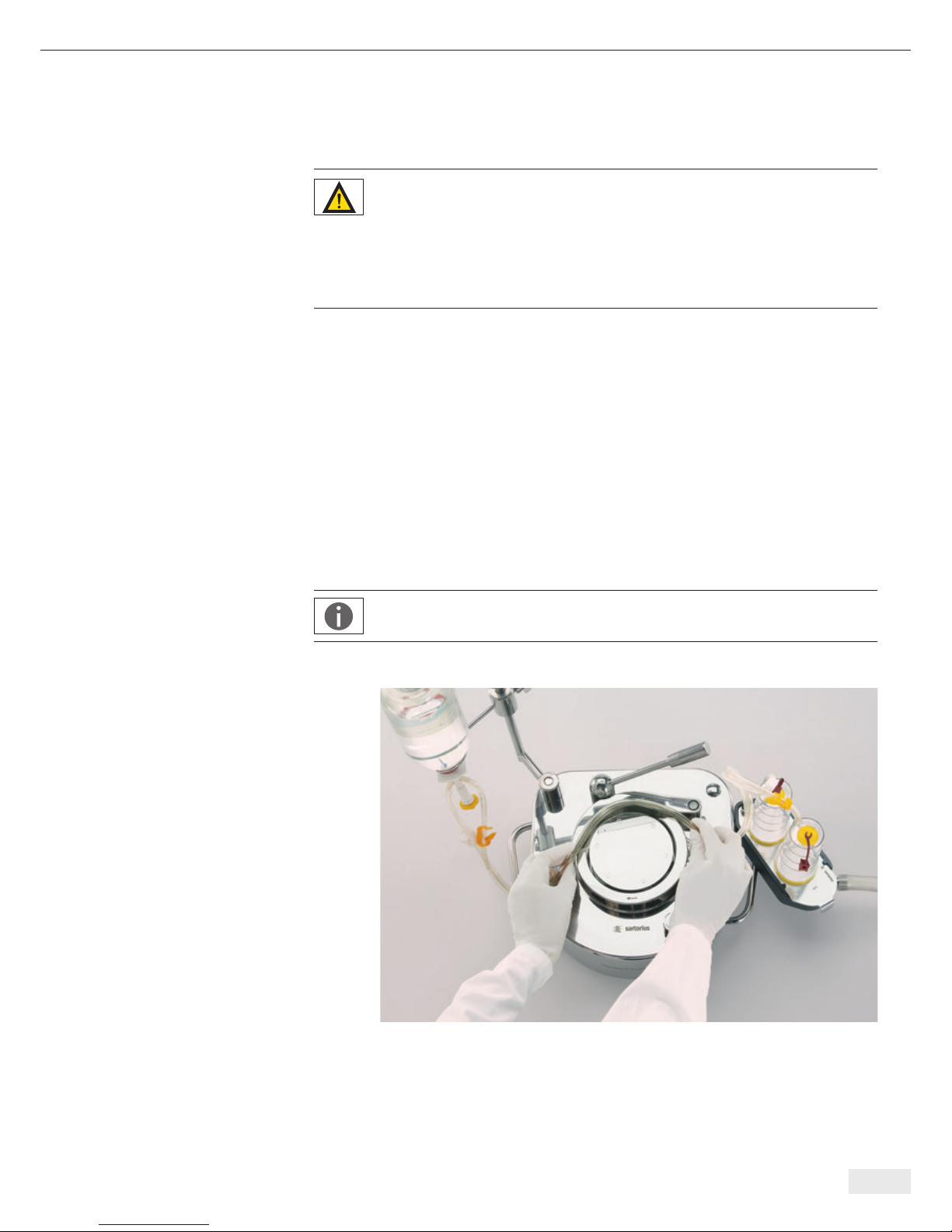
– Now open the lever and the bow.
– Keep the tubing around the rotor of the pump so that no kinks occur and the tub-
ing is not under tension (the arrow on the fixed part surrounding the pump head
indicates the later direction of rotation, Fig.5). The tubing is attached by simply
inserting it (with it lying on the ground) and fastening the lever (3). In this way,
the tubing is automatically correctly positioned.
Important Note!
When threading the tubing, make sure that it is not kinked or twisted.
Fig. 5
– To start the pumping process, the tubing must be fully inserted and the lever
must be engaged. A safety function ensures that the pump does not start if the
lever or the bow are open.

– After threading the tubing and closing the lever, insert the removal spike|needle of
the Sterisart NF system as described in the instructions for the Sterisart NF sterility
test system. Then attach the test liquid container (e.g., bag or bottle) by hanging
it on the support rod (bag) or by placing it in the holding ring on the support rod
(bottle). The holding ring accepts bottles of various sizes. The holder must be turned
so that the sterility test system tubing is not under tension after the spike|needle
has been inserted and so that the spike|needle cannot slip out of the container.
For testing ampoules, an ampoule breaker is also attached to the support rod.
Use the integrated knife to scratch the neck of the ampoule, then snap off the top.
The broken-off top of the ampoule falls into the collection container (which can
be emptied later).
– For the following pumping process, make sure that the Sterisart NF sample
containers are correctly positioned in the intended holders, and that the tubing has
been inserted without tension or kinking.
Important Note!
When the lever is opened, the Sterisart Universal pump is turned off
immediately by a safety function. In this event, the Sterisart Universal
pump can be restarted after adequately closing all components.
6.1 Operating the Sterisart Universal Pump 16420
All operating parameters of the Sterisart Universal pump 16420 are saved in
programs. Once you have switched on the pump, it will enter the first program
saved (default = “Manual”). Press the right-hand soft key Menü (German for “menu”)
to access the list of programs (program menu).
The following programs are predefined:
1. Manual
see section 6.1.1
2. Manual Record
see section 6.1.2
14 Application
6.1.1 Manual Program
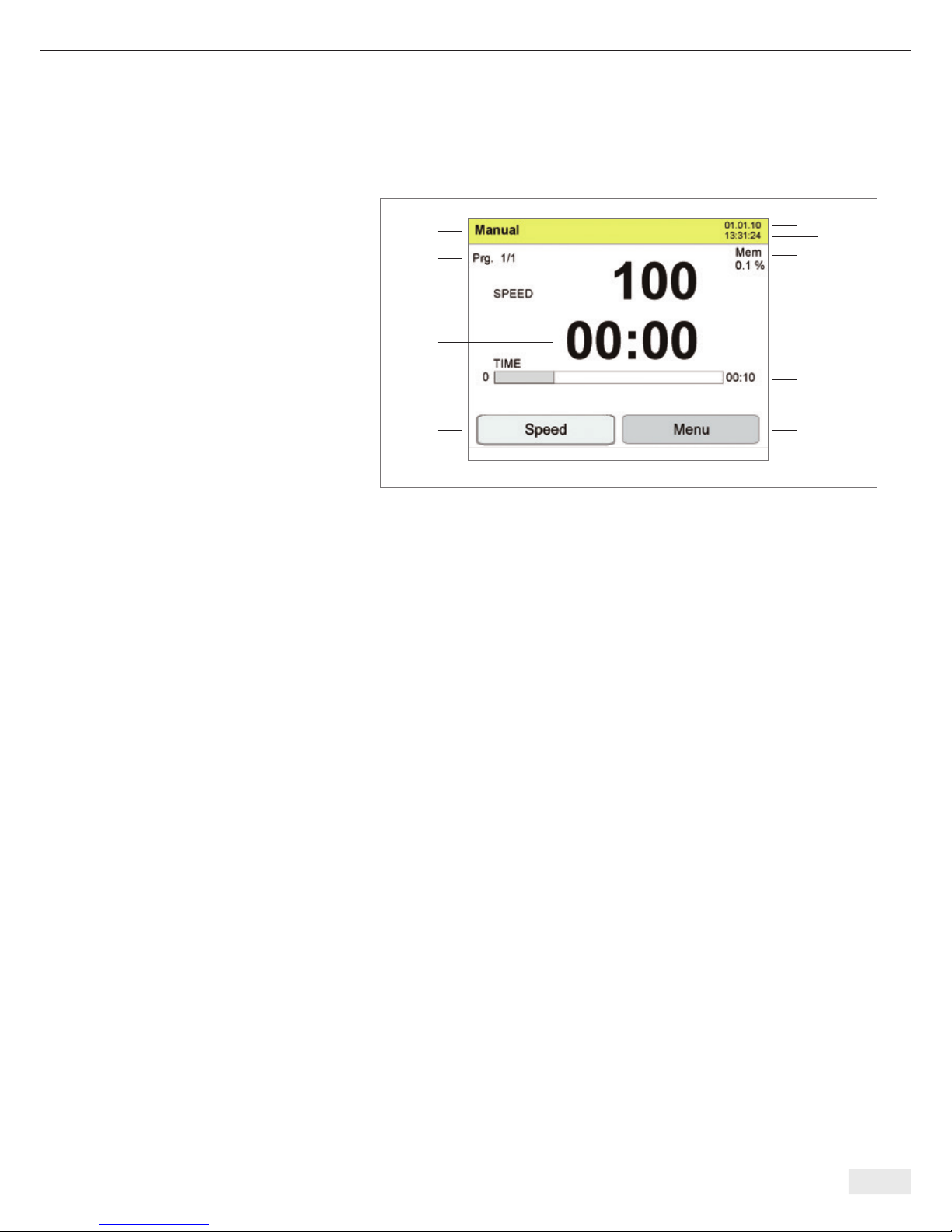
We will use the Manual program here as an example to explain all the information
that can be displayed (Fig. 6):
Fig. 6
The following information is shown in the display (Fig. 6):
1: Operating mode (Manual)
2: Current program step (here: Prg. 1/1)
3: Date (dd:mm:yy)
4: Time 24h
5: Speed, factory-set
6: Level of memory capacity already used (Mem: indicates the amount of memory
used in %. Please note: 50 data records (see 6.1.2) take up approx. 1% of the
internal memory capacity).
7: Pump time (current) (shows how long the pump has been running)
8: Preprogrammed pump time (in the Manual operating mode, this setting is 0;
i.e., inactive so that this information is not shown on the display .
9: Soft key: current function (in this case: Speed). The white background indicates
that the value (Speed) can be changed (by turning the selecting knob). If the soft
key does not have a white background (Esc key pressed), the value cannot be
changed. Pressing the soft key (Speed) again returns it to a white background.
Pressing the soft key with a white background (current function: Speed) switches
the display to Duration. Here the preprogrammed pump time can be changed
(turning the selecting knob). If the soft key does not have a white background
(Esc key pressed), the value cannot be changed. Pressing the soft key (Duration)
again, returns it to a white background. Here you can return to the Speed display
by re-pressing the soft key (Duration).
Soft key: current function (in this case: Speed). The black background indicates that
you can change this value (Speed) (by turning the selecting knob). If the soft key
does not have a black background (Esc key pressed), the value displayed cannot be
changed. Pressing the soft key (Speed) again returns it to black background.
When you press the soft key with a black background (current function: Speed),
the display will change to Duration. Here you can change the preprogrammed
time by turning the selecting knob. If the soft key does not have a black back-
ground (Esc key pressed), the value cannot be changed. Pressing the soft key
(Duration) again, returns it to a black background. Here you can press the soft
key (Duration) one more time to return to the Speed display.
10: Soft key: Menu (for selecting the individual programs: Program Menu)
Application 15
3
1
2
5
7
9
4
6
8
10

16 Application
Program Sequence
The pump is in the basic operating state (Manual program). To start the pumping pro-
cess, press the selecting knob or the foot switch. To stop the pump, press the selecting
knob or the foot switch again. In this case, you can change the pump
rate (Speed) before and during a pumping procedure in a range between 10 – 100
(infinitely; does not correspond to revolutions per minute).
After re-pressing the left Speed soft key, the Duration soft key is available.
A specific pump time can be entered via Duration.
Note: When you enter a specific pump time in Duration, the current pump
time is set to zero.
The Esc key has two different functions, depending on the state of the program:
a) The left soft key (Speed|Duration) has a white background (active). Pressing the
Esc key deactivates the current soft key function (Speed|Duration) so that the
respective value (Speed|Duration) can no longer be set (no white background).
b) The left soft key (Speed|Duration) does not have a white background (inactive).
By pressing the Esc key, the current pump time is reset.
To switch off the pump, use the On|Off switch on the back panel of the pump
housing.
6.1.2 Manual Record Program (Manual Operating Mode with Data Collection)
For preparing the pump for initial start-up, see Chapter 6.
This mode is reached by pressing the Menu key once. The Program Menu appears
on the display and lists the following options (Fig. 7):
a) Manual
b) Manual Record
The different operating modes are selected by turning the selecting knob.
For final selection of an operating mode, press the selecting knob (in this case:
Manual Record).
The difference between the Manual program and this Manual Record program is that
when the latter begins, a data record can be collected in the manual mode.
The display will now prompt a barcode scan (Scan Operator, Fig. 8).
The control unit now waits until either data recording is started by pressing the left
Scan soft key (barcode is scanned via the internal barcode scanner), the current data
set recording (current scan process) is bypassed by pressing the Esc key or the program is stopped and returned to the Program menu by pressing the Menu key.
Note: The Scan soft key does not have to be pressed for an external scanner.
The control unit automatically reads the data from the external scanner and
assigns it to the appropriate data records. In the example in Fig. 8, this data is
assigned to the “Operator“ parameter. The control unit automatically switches
to the next parameter as soon as the data have been scanned.
Fig. 7
Fig. 8

Application 17
Fig. 9
To read in a barcode, hold it under the laser beam within 10 seconds after you have
pressed the Scan key (see Fig. 9). If no barcode is recognized or read in during this
time, press the Scan key again to repeat this procedure. A successful scanning process
is confirmed by an acoustic signal. At the same time, the barcode recognized is shown
on the display for approx. 1 second.
Follow the same procedure to scan in the 5 additional barcodes in the order given
below:
– Scan sterility test unit
– Scan sample
– Scan rinsing fluid
– Scan tryptic soy (TSB)
– Scan thioglycollate (FTM)
You can press the Esc key at any time during scanning to skip an item.
After scanning, the pump will be in the basic operating state as in Manual Program
(see section 6.1.1)
At the end of the sterility test, the data records collected can be output using a PC
or an optionally available MMC/SD card reader.
For more on the topic of data evaluation, see separate instructions for use.
7 Configuring the Sterisart Pump
Press the Menu soft key twice to go to the pump’s configuration menu (Fig. 10).
Here, the following parameters can be set.
If you do not press any key or switch within 60 seconds (default can be changed in
menu item “Operation Timeout Menu“), you will automatically exit from the system
menu and the pump will return to the last program step it was performing.
In general, a changed value is first saved by pressing the selecting knob. You can also
exit the System menu by pressing the Esc key. In this way, the set value is not applied.
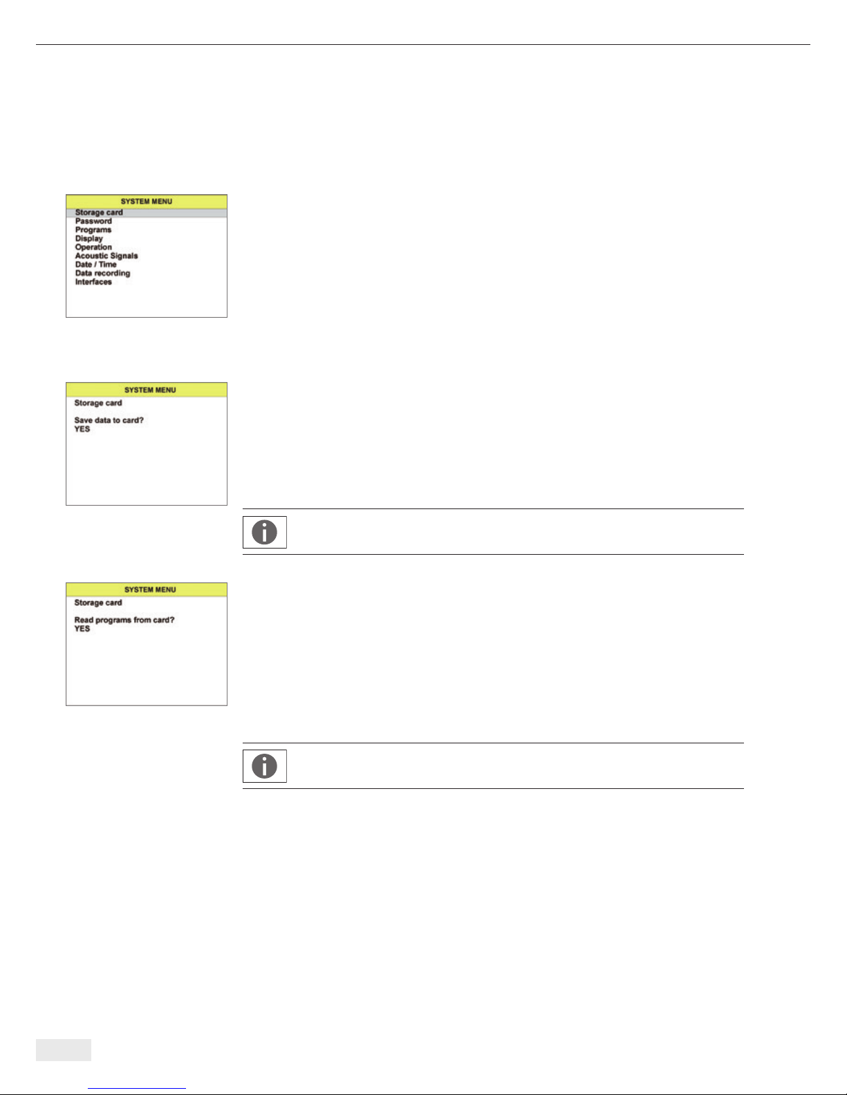
Storage Card (Memory Card)
To access this menu, you will first need to connect an external card reader and insert
an MMC/SD. Interface configuration is not required.
Save data to card (Fig. 11):
Default setting: No
Selectable options: No|Yes
By confirming this menu prompt (selectable option: Yes), all data records logged up
to this point will be transferred to the MMC/SD card in the card reader and deleted
from the pump memory to provide free memory space. Active data transfer is
indicated by a series of bars. While this is being displayed, do NOT remove the card.
Note: If there is no MMC/SD card in the card reader, the “File error” error
message is displayed.
Read programs (Fig. 12):
Default setting: No
Selection options: No|Yes
By pressing Okay to confirm this prompt (selectable option: YES), the program
structure currently on the storage card will be transferred to the pump. Active data
transfer is indicated by a series of bars. While this is being displayed, do NOT remove
the card.
Here, it is important that the current program be in the root directory (main
directory) of the card and exactly matches the file name “Programm.smm.”
18 Configuring the Sterisart Pump
Fig. 10
Fig. 11
Fig. 12

Configuring the Sterisart Pump 19
Fig. 13
Fig. 14
Password
Inputting a password (Fig. 13):
Default setting: 0
Minimum value: 0
Maximum value: 29999
The password can be a 5-digit number and it is entered using the selecting knob.
Password entry must be confirmed by re-pressing the selecting knob.
Entries visible for the user in the System menu are released by entering two freelyselectable passwords. These levels are then accessible to all users without the further
need of entering a password. The following relationship exists between the respective
password and the entries in the System menu.
Password 1:
Password factory setting 101
Levels: Memory card, password,
Programs, display,
Operation, audio signals
Password 2:
Password factory setting 202
Levels: Memory card, password,
Programs, display,
Operation, audio signals,
Date|Time, data recording, interfaces
Note: If there is no agreement with the saved password and the password just
entered, the system automatically returns to the System menu.
After entering the password, the user can change the respective default password.
The following relationship exists between the password entered at the beginning and
the changes that can be made to the default passwords:
Changing password 1 (Fig. 14):
Default setting: 101
Minimum value: 0
Maximum value: 29999
The 101 default password can be changed in this menu.
Changing password 2:
Default setting: 202
Minimum value: 0
Maximum value: 29999
The 202 default password can be changed in this menu.
Note:
When entering password 2, the user also has the option of changing password 1.

Fig. 15
Programs (Fig. 15):
Using this menu item, adjustments can be made to the program step that is currently
activated. In detail, these are:
Speed Minimum
Default setting: 10
Minimum value: 10
Maximum value: 100
This parameter displays the lower limit value of the speed of the current program step
down to which the later user may change the speed.
Standard Speed
Default setting: Current speed
Minimum value: Speed Minimum
Maximum value: Speed Maximum
This value displays the speed of the current program step. The operator can change
the speed within the limit values Speed Minimum and Speed Maximum.
Speed Maximum
Default setting: 100
Minimum value: 10
Maximum value: 100
This parameter displays the upper limit value of the speed of the current program
step up to which the later user may change the speed
Speed Steps (Increments)
Default setting: 10
Minimum value: 1
Maximum value: 10
This value represents the amount the current speed is increased or reduced by turning
the wheel by one position.
Speed Adjustment Timeout [s]
Default setting: 0 s (Speed soft key always with white background)
Minimum value: 0 s (Speed soft key always with white background)
Maximum value: 120 s
The Speed soft key looses the white background (becomes inactive) if the key is not
pressed before this time expires. The soft key would then have to be pressed again
to make a new change to the Speed value.
The value 0 means that the time period does not end, i.e. the soft key no longer
deactivates automatically.
Duration Minimum [s]
Default setting: 0 s (infinite pump time)
Minimum value: 0 s (infinite pump time)
Maximum value: 1800 s
This parameter represents the lower limit value of the current program step‘s duration down to which the later user may change the duration
20 Configuring the Sterisart Pump
 Loading...