

Sartorius Signum 1,Signum 3,Signum 2,SIWRDCP,SIWADCP,SIWSDCSP,SIWSDCP,SIWABBP,SIWSBBP Operating Instruction
Operating Instruction
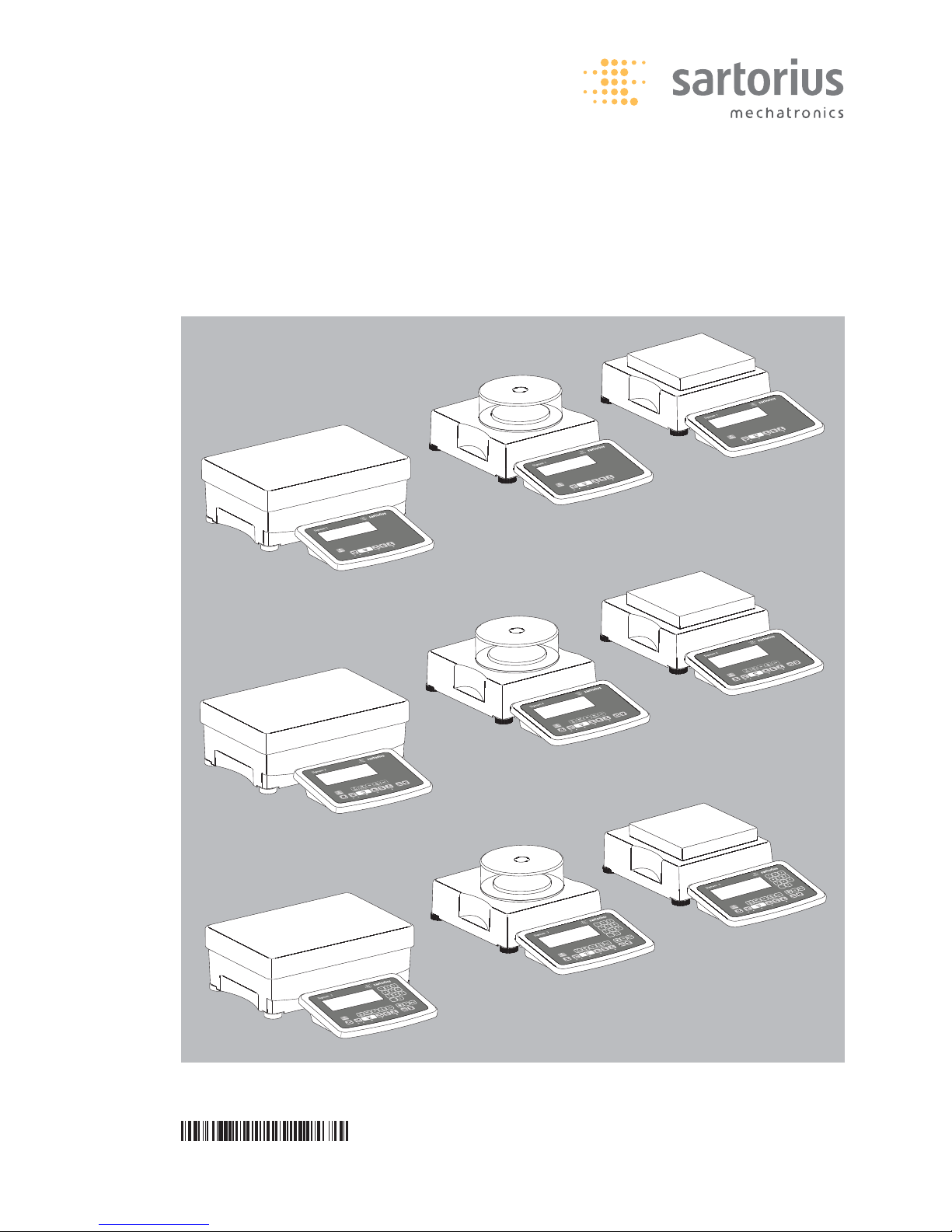
Sartorius Signum 1| Signum 2 | Signum 3
Models SIWRDCP | SIWADCP | SIWSDCP | SIWSDCSP | SIWABBP | SIWSBBP
Complete Scales
98648-014-73

Signum 1, 2 and 3 are precise and
rugged complete scales that give you
reliable weighing results.
The Signum Series of compact scales
includes models with strain-gauge
weighing systems as well as versions
equipped with monolithic technology,
using the principle of electromagnetic
force compensation.
These compact industrial scales offer
the following special features:
– Rugged and durable Sartorius quality
– Flexible options for display unit
installation
– Wide range of configuration options
for customized operation
– Variety of optional data interfaces
– Optional IP65 protection from dust and
jets of water
– Optional versions for use in zone 2
and 22 hazardous areas
– High quality workmanship and materi-
als
– Choice of application levels
– Available in weighing capacities
between 3 kg and 60 kg; choice of res-
olutions available for each capacity
– Verifiable models in accuracy
classes k (SIWS) and l (SIWR)
– Preload values can be defined
(for equipment installed on the scale)
Additional features include:
– Large keys with positive click action
– Numeric and alphabetic input
– Large backlit 14-segment display
– Connectivity for two weighing plat-
forms (digital platform or, using an
optional A/D converter, analog plat-
form)
Advantages in routine weighing tasks:
– Fast response times
– Independence from location of platform
installation
– Designation of weight values with up
to 4 lines of alphanumeric text
– Flexibility afforded by diversity of
interfaces
– Security through password protection
Range of Models
Three different types of weighing technology are used in the Signum Series,
offering different performance levels:
Signum Regular
(SIWRDCP Models)
– Standard weighing system
(all SIWR models)
– Resolutions up to 35,000d
– Models verified at the factory for use
in legal metrology, Class l, with:
2+3000/3500e (dual range);
1+6000/7500e and
1+3000e (single range)
– The single-range scales with variable
scale intervals are available with your
choice of fixed or adjustable fine range
Signum Advanced
(SIWADCP Models)
– Mechatronic weighing system
(all SIWA… Models)
– Resolutions up to 65,000d
(Models SIWABBP)
– Mechatronic weighing system
– Resolutions up to 150,000d
Signum Supreme
(SIWSDCP Models)
– Monolithic weighing system
(all SIWS Models)
– Resolutions up to 350,000d
(all SIWSBBP Models)
– Monolithic weighing system
– Resolutions up to 620,000d
– Models verified at the factory for use
in legal metrology, Class K, with:
1+30,000e; 1+62,000e (e=d);
1+6000e; 31,000e,61.000e
(single and dual range);
16,000e (single and dual range, each
with internal motorized calibration
weight)
– The single-range scales with variable
scale intervals are available with your
choice of fixed or adjustable fine range
Signum Supreme featuring
a stainless steel housing
(SIWSDCS Models)
– Monolithic weighing system
(all SIWS models)
– Resolutions up to 350,000d
– Models verified at the factory for use in
legal metrology, Class K, with:
1+30,000e (e=d); 1+6000e; 35,000e
(single and dual range); 16,000e
(single and dual range, each with
internal motorized calibration weight)
– The dual range scales are available with
your choice of fixed or adjustable fine
range
Signum Regular, Advanced and
Supreme models are all available with
applications levels 1, 2 and 3.
Symbols
The following symbols are used in
these instructions:
§ denotes general operating instructions
$ indicates instructions for exceptional
cases
> describes the outcome of an
operating step
!indicates a hazard
For technical advice on applications,
call the hotline at:
Phone (in Germany):
+49(0)551.308.4440
Fax (in Germany):
+49(0)551.308.4449
Intended Use
2

Intended Use 2
Warnings and Safety Precautions 4
Getting Started 5
Unpacking the Scale 5
Equipment Supplied 5
Installation 5
Conditioning the Scale 5
Checking the Geographical Data
for Use in Legal Metrology 5
Installing the Display and
Control Unit 6
Leveling the Weighing Platform 8
General View of the Equipment 9
Display and Keypad 9
Back Panel 9
Operating Design 10
Input 10
Keypad Input 10
Input Through the Digital
Control Port 11
Input Using a Bar Code Scanner
or External Keyboard 11
Display Modes 12
Measured Value Display 13
Saving Data in Weighing Mode 13
Operating Menu Navigation 14
Error Codes 15
Data Output 15
Saving Data 15
Configuration 16
Setting the Language 16
Configuring a Password 17
Operating Menu Overview 18
Operation 38
Basic Weighing Function 38
Weighing W 38
Device Parameters 38
Tare Function in Weighing 39
Numeric Input for Weighing 40
Weighing with Variable Tare Values 41
Calibration and Adjustment 42
SQmin Function 46
Data ID Codes 48
Combining Application Programs 50
Counting 51
Neutral Measurement 55
Averaging 58
Weighing in Percent 61
Checkweighing 64
Checkweighing toward Zero 67
Classification 68
Totalizing 71
Net-total Formulation 74
Examples of Application
Combinations in Signum 3 78
Configuring Printouts 80
Interface Port 83
Connecting a Second Weighing
Platform 84
Pin Assignment Chart 84
Pin Assignments for COM1 84
Pin Assignments for UniCOM 84
Wiring Diagram (Display and
Control Unit <—> Computer) 85
Configuring the Data Interface
as a COM Port 86
Data Input Format 86
Data Output Format 87
Configuring the Data Interface
as a Printer Port 88
Automatic Data Output (SBI) 89
GMP-compliant Printouts 90
Error Codes 91
Care and Maintenance 92
Recycling 92
Overview 93
Common Specifications 94
Signum Model Designator 94
Details on Available Resolutions 95
Model-specific Specifications 96
Dimensions (Scale Drawings) 99
Accessories 101
Declaration of Conformity 104
EC Type-Approval 107
Plates and Markings 109
Index 114
Appendix
General Password 117
Contents
3

Signum scales comply with the
European Council Directives as well as
international regulations and standards
for electrical equipment, electromagnetic compatibility, and the stipulated
safety requirements.
§ To prevent damage to the equipment,
read these installation instructions
carefully before using your Signum
scale.
!Do not use this equipment in hazardous
areas. If you use electrical equipment
in installations and under ambient
conditions subject to stricter safety
standards than those described in the
manual, you must comply with the
provisions as specified in the applicable
regulations for installation in your
country.
!The display and control unit may
be opened only by authorized service
technicians who have been trained by
Sartorius and who follow Sartorius’
standard operating procedures
for maintenance and repair work.
!Make absolutely sure to unplug the
display and control unit from power
before you connect or disconnect
any electronic peripheral devices to
or from the interface port.
– On request, Sartorius will provide infor-
mation on the minimum operating
specifications (in accordance with the
standards for defined immunity to
interference).
!If the equipment is exposed to excessive
electromagnetic interference, it can
affect the value displayed. Once the
disturbance has ceased, the instrument
can be used again in accordance with
its intended purpose.
– Connect only Sartorius accessories and
options, as these are optimally designed
for use with your Signum scale.
– Warning when using pre-wired RS-232
connecting cables: RS-232 cables
purchased from other manufacturers
often have pin assignments that are
incompatible with Sartorius products.
Be sure to check the pin assignments
against the chart in this manual before
connecting the cable, and disconnect
any lines identified differently from
those specified by Sartorius.
$ If there is visible damage to the
equipment or power cord, unplug
the equipment and lock it in a secure
place to ensure that it cannot be
used for the time being.
– Use only extension cords that meet
the applicable standards and have
a protective grounding conductor.
!Disconnecting the ground conductor
is prohibited.
– Note on installation:
The operator shall be responsible for
any modifications to Sartorius equipment and for connections of cables not
supplied by Sartorius and must check
and, if necessary, correct these modifications.
If Option L8 (24-volt module) for connection to low-voltage sources is used,
be sure to comply with the requirements for safety extra low voltage
(SELV) and protective extra low voltage
(PELV).
NOTE:
This equipment has been tested and
found to comply with the limits
pursuant to part 15 of FCC Rules.
These limits are designed to provide
reasonable protection against harmful
interference. This equipment generates,
uses and can radiate radio frequency
energy and, if not installed and used
in accordance with these instructions,
may cause harmful interference to
radio communications. For information
on the specific limits and class of this
equipment, please refer to the Declaration of Conformity. Depending on the
particular class, you are either required
or requested to correct the interference.
If you have a Class A digital device,
you need to comply with the FCC statement as follows:
“Operation of this equipment in a
residential area is likely to cause harmful interference in which case the user
will be required to correct the interference at his own expense.” If you have
a Class B digital device, please read
and follow the FCC information given
below:
“[…] However, there is no guarantee
that interference will not occur in a
particular installation. If this equipment
does cause harmful interference to
radio or television reception, which can
be determined by turning the equipment off and on, the user is encouraged
to try to correct the interference by one
or more of the following measures:
– Reorient or relocate the receiving
antenna.
– Increase the separation between
the equipment and receiver.
– Connect the equipment into an
outlet on a circuit different from
that to which the receiver is
connected.
– Consult the dealer or an experienced
radio/TV technician for help.”
Before you operate this equipment,
check which FCC class (Class A or Class
B) it has according to the Declaration of
Conformity included. Be sure to observe
the information of this Declaration.
– Do not expose the equipment
to aggressive chemical vapors or to
extreme temperatures, moisture,
shocks, or vibration.
– Clean your Signum scale only in accor-
dance with the cleaning instructions
(see “Care and Maintenance”).
$ If you have any problems with your
Signum scale: contact your local
Sartorius office, dealer or service center.
IP Rating
Industrial protection ratings for the
housing:
– All models are rated to IP43 (if Option
I65 was ordered; the equipment is rated
to IP65)
– The IP43 (or optional IP65) protection
rating for the display and control unit
is ensured only if the rubber gasket
is installed and all connections are
fastened securely (including the caps on
unused sockets). Weighing platforms
and equipment must be installed and
tested by a certified technician.
– If you install an interface port or
battery connector after setting up your
Signum, keep the protective cap(s) in
a safe place to be used for protecting
the interface port or battery connector
when not in use, or prior to shipment.
Do not leave the interface ports un-
covered. If you are not using a parti-
cular connector, replace the cap
to protect the data interface from
vapors, moisture and dust or dirt.
Using the Equipment in
Legal Metrology
– If the scale is to be verified, make sure
to observe the applicable regulations
regarding verification.
– If any of the verification seals are
damaged, make sure to observe
the national regulations and standards
applicable in your country in such
cases. In some countries, the equipment
must be re-verified.
Warnings and Safety Precautions
4

Unpacking the Scale
§ After unpacking the equipment,
please check it immediately for any
external damage.
$ If you detect any damage, proceed
as directed in the chapter entitled
“Care and Maintenance,” under
“Safety Inspection.”
$ Save the box and all parts of the
packaging for any future transport.
Unplug all connected cables before
packing the equipment.
Equipment Supplied
– Complete scale
– Operating instructions (this manual)
– Special accessories as listed on the
bill of delivery, if ordered
Installation
Choose a location that is not subject
to the following negative influences:
– Heat (heater or direct sunlight)
– Drafts from open windows and doors
– Extreme vibrations during weighing
– Excessive moisture
Conditioning the Scale
Moisture in the air can condense on
cold surfaces whenever the equipment
is moved to a substantially warmer
place. To avoid the effects of conden-
sation, condition the scale for about
2 hours at room temperature, leaving
it unplugged from AC power.
Equipment not in Use
Switch off the equipment when
not in use.
Checking the Geographical Data
Entered for Use in Legal Metrology
(SIWR Models Only)
Preparation
(See also the “Device Information”
menu items listed under “Operating
Menu Overview” in the chapter
entitled “Configuration.”
§ Press the e key to turn on the scale
§ While all segments are lit,
press the T key
>
Appl is displayed
§ To select “Device-specific information,”
press k repeatedly; press T
to confirm
§ To switch the display between
information on weighing platform 1
and weighing platform 2, press k
repeatedly; press T to confirm
> View geographical data (configured
prior to verification); for example:
Latitude (in degrees):
51
4
Altitude (in meters): 513
5
or
Gravitational acceleration (in m/s
2
):
9,810
6
The scale can be used in legal
metrology anywhere in Germany if the
geographical data is as follows:
– Latitude: 51.00 degrees
– Altitude: 513 m
This data corresponds to the following
value:
– Gravitational acceleration: 9.810 m/s
2
These values are calculated for Germany
based on a mean value for the Earth’s
acceleration. The greater the precision
of the geographical data entered, the
greater the precision achieved with
the weighing instrument; the tolerance
range, however, is restricted accordingly
(see above).
The tolerances ranges, for example
for a scale with 3000e, are as follows:
– ± 100 for the latitude, and
– ± 200 for the elevation above sea level.
!If used outside the specified zone,
the scale must be re-verified for
use in legal metrology: Please contact
an authorized service technician.
Getting Started
5

Installing the Display and Control Unit
The following options are available for installing the display and control unit:
– Attached to the front of the weighing platform
– On a column; part number YDH01P (optional)
Fastening the display and control unit to the weighing platform:
§ Guide the display and control unit onto the retainer bracket.
§ Level the weighing platform (see page 7).
Operating the display and control unit separately:
§ Turn the weighing platform over and place it on a soft surface to avoid damaging
the weighing system.
§ Remove the display and control unit retainer bracket.
§ Take the cable out of the cable channel.
§ Turn the weighing platform right side up and place it so that it rests on its feet.
§ Level the weighing platform (see page 8).
Installing the display and control unit on the YDH01P column:
§ Turn the weighing platform over and place it on a soft surface to avoid
damaging the weighing system.
§ Remove the display and control unit retainer bracket.
§ Take the cable out of the cable channel.
§ Use the four hexagonal screws provided (M4+8) to attach the column
to weighing platform (back panel facing downward).
§ Turn the weighing platform right side up and place it so that it rests on its feet.
Getting Started
6
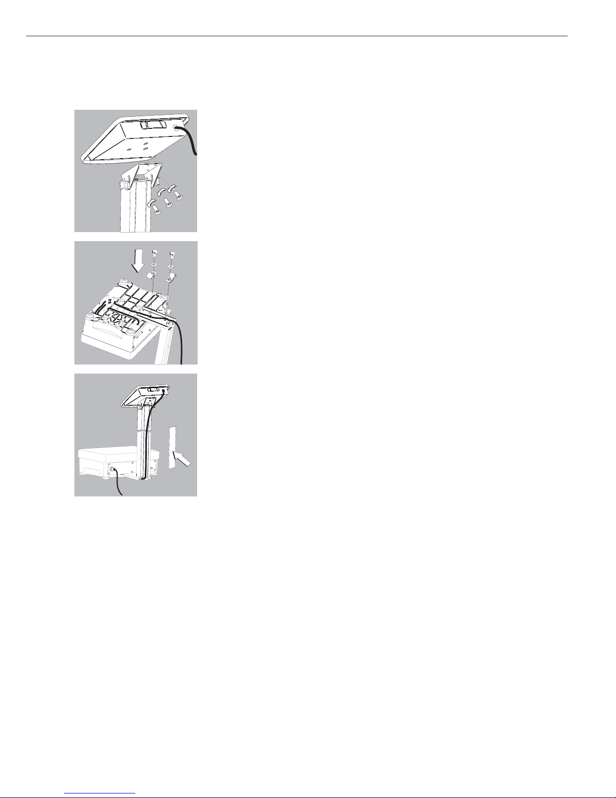
§ Loosen the two locking bolts at the top of the column to facilitate installation
of the display and control unit.
§ Use the 6 hexagonal screws to attach the display and control unit to the top
of the column.
§ Adjust the display and control unit to the desired angle and
tighten the locking bolts at the top of the column.
§ A recessed space is provided in the scale base, accessed from the bottom of the scale,
for any excess length of cable.
§ Guide the connecting cable along the channel on the bottom of the weighing platform.
§ Use the cable clamps provided to affix the cable that connects the display and control
unit to the weighing platform to the bottom of the column.
§ Turn the weighing platform right side up and place it so that it rests on its feet.
§ Attach the cable retainer to affix the cable connecting the display and control
unit to weighing platform to the back of the column.
7

Connecting the Scale to AC Power
§ Check the voltage rating and the plug design.
$ The equipment is powered through the installed power cord. The power supply is
built into display and control unit, which can be operated with a supply voltage of
100 Vac to 240 Vac.
Make sure that the voltage rating printed on the manufacturer's ID label is identical
to that of your local line voltage. If the voltage specified on the label or the plug design
of the AC adapter do not match the rating or standard you use, please contact your
Sartorius office or dealer.
The power connection must be made in accordance with the regulations applicable in
your country.
To power a device of protection class 1, plug the power cord into an electrical
outlet (mains supply) that is properly installed with a protective grounding conductor
(protective earth = PE). The power plug or a different, suitable disconnecting device for
the power must be easily accessible.
Safety Precautions
If you use an electrical outlet that does not have a protective grounding conductor,
make sure to have an equivalent protective conductor installed by a certified electrician
as specified in the applicable regulations for installation in your country. Make sure
the protective grounding effect is not neutralized by use of an extension cord that lacks
a protective grounding conductor.
Warmup Time
To deliver exact results, the scale must warm up for at least 30 minutes after initial
connection to AC power or after a relatively long power outage. Only after this time will
the scale have reached the required operating temperature.
Using Equipment Verified as Legal Measuring Instruments in the EU*:
$ Make sure to allow the equipment to warm up for at least 24 hours after initial
connection to AC power or after a relatively long power outage.
Connecting a Bar Code Scanner (Accessory; Order No. YBR02FC)
!Disconnect the display and control unit from AC power (unplug the AC adapter)
$ Installation:
please see “Pin Assignment Charts" in this manual (implemented via the YCC02-BR02
connecting cable or as Option M8)
Leveling the Weighing Platform
Purpose:
– To compensate for uneven areas at the place of installation
– To ensure that the equipment is placed in a perfectly horizontal position
for consistently reproducible weighing results
Always level the weighing platform again any time after it has been moved
to a different location.
§ Level the weighing platform using the four leveling feet. Turn the feet until
the air bubble is centered in the level indicator.
§ Check to ensure that all leveling feet rest securely on the work surface.
> Each of the leveling feet must support an equal load.
> Adjusting the leveling feet:
To raise the weighing platform, extend the leveling feet (turn counterclockwise).
To lower the weighing platform, retract the leveling feet (turn clockwise).
* Including the Signatories of the Agreement on the European Economic Area
Getting Started
8
9
Reference
REF
Signum 3
n
Scale
#
Zero
0
Tare
T
Function
Fn
Print
ISOTest
Resolution
x10
NET
B/G
ID
Mem
On
Standby
Info
CF
Clear
Function
Toggle
OK
0
.
2 3
987
4 5 6
1
A
10
9
8
7
16
15
14
13
12
11
17
18
19
1
2
3
4
5
6
Info
n
Scale
#
Zero
0
Tare
T
Function
Fn
Print
ISOTest
On
Standby
Resolution
x10
NET
B/G
CF
Clear
Function
Toggle
Reference
REF
OK
Signum 2
A
10
9
8
7
16
15
17
18
19
1
2
3
4
5
6
Zero
0
Tare
T
Function
Fn
Print
ISOTest
On
Standby
Signum 1
A
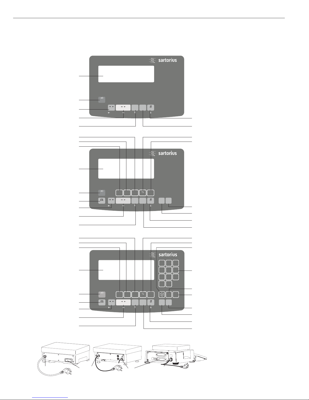
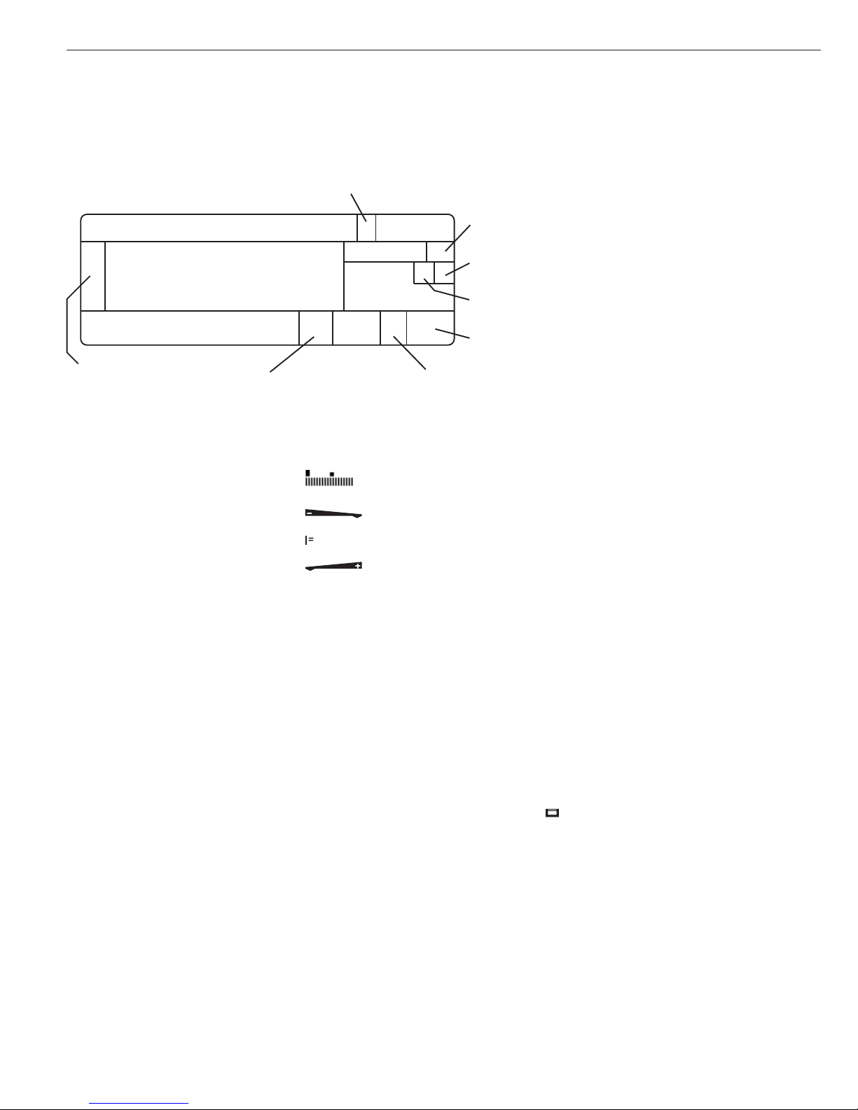
Display and Keypad
1 Display (for details, see the chapter
entitled “Operating Design”)
2 On/off key
3 Toggle key (toggle display between
weighing platforms)
4 Zero key
5 Tare key
6 Function key (toggle between gross
and net values)
7 Start calibration or adjustment
8 Print key (data output)
9 Toggle unit between normal and
10-fold higher resolution
10 View gross value (net value plus tare)
View net value (gross value minus tare)
11 Save data
12 ID key (for entering operator ID)
13 Alphanumeric keypad
14 Toggle between application program
and application-specific information
15 Info key
(shows ID codes and tare values)
16 Toggle key
(function depends on application)
17 OK key
(function depends on application)
18 Reference value key
(function depends on application)
19 Clear function key (function
depends on active application)
Back Panel
20 RS-232C interface (COM1)
(standard equipment)
21 Power cord connection
General View of the Equipment
Signum 1
Signum 2
Signum 3
2021
8
7
1
2
4
5
6
2021 21
Keys
Operation of the Signum 1, Signum 2
or Signum 3 scale involves just a few
keys. These keys have one function
during measurement and another
during configuration. Some of the keys
have one function when pressed briefly,
and another activated by pressing
and holding the key for longer than
2 seconds.
If a key is inactive, this is indicated
as follows when it is pressed:
– The error code “———-” is displayed
for 2 seconds. The display then returns
to the previous screen content.
You can use Signum 2 or 3 to collect
weight values from two weighing
platforms, calculate and display weight
values using application programs,
and assign IDs to the samples weighed.
Configure the display and control
unit first, using the operating menu
to prepare the desired application
program (printer settings, etc.).
Then you can begin weighing.
Input
Keypad Input
Labeled Keys
Some keys have a second function,
activated by pressing and holding
the key for over two seconds.
Whether a function is available
depends on the operating state
and operating menu settings.
e On/off
(in standby mode,
Off is
displayed).
Signum 2 and 3 only:
n If a second weighing platform
is connected, this key toggles the
display between the two readouts.
( – Zero the scale
– Cancel calibration/adjustment
) – Tare the scale
k Toggle between 1
st
and 2ndweight
unit, or gross and net values,
or normal and 10-fold higher resolution, depending on operating
menu settings (depends on model)
J Start calibration or adjustment
p – To print: press briefly.
– To print GMP footer:
Press and hold (> 2 seconds)
Signum 3 only:
I To toggle the scale to Info mode
Signum 3 only:
d ID key (for entering operator ID)
Signum 2 and 3 only:
K Toggle unit between normal and
10-fold higher resolution
Signum 2 and 3 only:
l Net-gross value key
Signum 2 and 3 only:
w Toggle between display modes
within an application program
Signum 2 and 3 only:
r Lets you modify reference values
Signum 2 and 3 only:
O Saves a value or starts an application
program.
Signum 3 only:
R Saves a value in product data
memory
Signum 3 only:
D Toggle applications
Operating Design
10
Reference
REF
Signum 3
n
Scale
#
Zero
0
Tare
T
Function
Fn
Print
ISOTest
Resolution
x10
NET
B/G
ID
Mem
On
Standby
Info
CF
Clear
Function
Toggle
OK
0
.
2 3
987
4 5 6
1
A
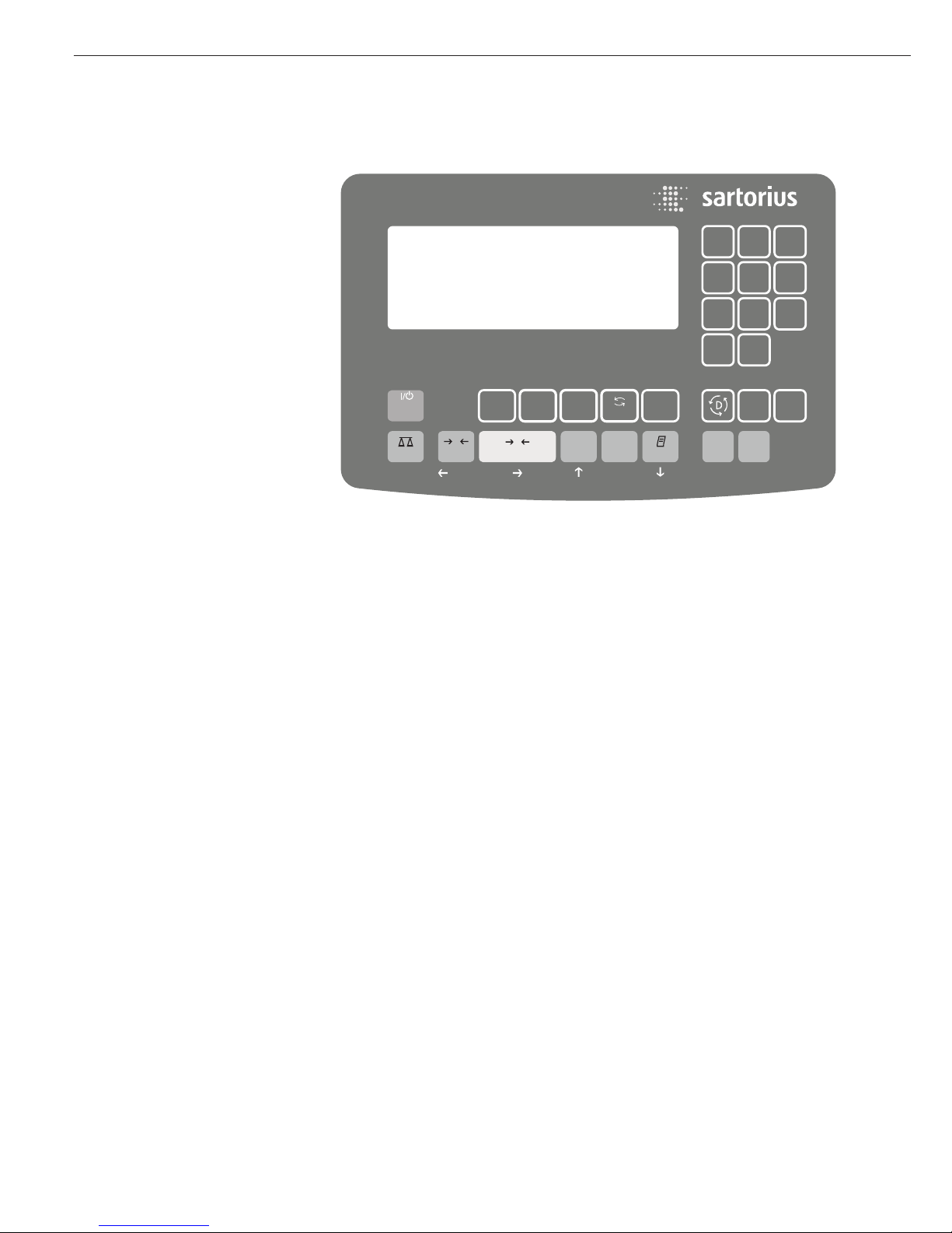
Operating Elements: Signum 3

11
Signum 2 and 3 only:
I Press to view either application data
or manual tare values, depending
on the key pressed subsequently
(e.g., ))
Signum 2 and 3 only:
c – Quit an application or delete an
input character
Signum 3 only:
0, 1, 2 … 9
Enter numbers, letters and other
characters
Numeric Input via the Keypad
(Signum 3 Only)
§ To enter numbers (one digit at a time):
Press 0, 1, 2 … 9
§ To save input:
Press the required key (e.g., )
to save manual tare input)
$ To delete a digit:
Press c
Loading a Tare Value from
the Weighing Platform
To save the weight on the
weighing platform as a tare weight:
Press the ) key
Input Through the Digital
Control Port
You can connect a remote hand switch
or foot switch to the input control line,
for use with all application programs.
Assign one of the following functions
to this switch in the Setup menu, under
Device parameters - Control input
(
ctrl io):
CTRL IO
CTRL INP
8
8.4 Universal IN
…
…
…
CTRL OUT
For a detailed list of menu items, please see
the chapter entitled “Configuration.”
Input over the ASCII Port
See page 86, “Data Input Format.”
Input using a Bar Code
Scanner or External
Keyboard
Input over a bar code scanner or
keyboard is handled by the Signum in
the same manner as keypad input:
– Weight values for tare memory
– Reference weight values for the
Counting, Neutral Measurement and
Weighing in Percent applications
– Numeric values
– Product identifiers
Signum 2 and 3 only:
Bar code scanner input can trigger
a function or load information for
display on the display and control unit.
You can configure this option in the
operating menu under
Barcode.
Con los ajustes REF y TARE se utliza el
valor del código de barras como valor
de referencia o valor de tara. Esta difer-
enciación puede realizarse también por
medio del código de barras. En barcode:
header aparece el valor en el display.
Measured value line
Application symbol
Bar graph
Plus/minus sign;
stability symbol
Unit
Tare assignment
Printing
is active
Scale weighing capacity
Calculated
value
Battery
symbol
GMP printing
is active
Reference value
for application
Data transfer
Memory
Counting:
reference sample updating/
automatic totalizing
Display Modes
There are two display modes:
– Normal operation (weighing mode)
– Operating menu (for configuration).
Weighing Mode: Display of Measured
and Calculated Values
Application, printing and battery
symbols:
The application symbol indicates the
selected program; for example:
A Counting application.
Other symbols shown here
include:
S Printing mode active
T GMP printing mode active
The battery symbol b indicates
the charge level of the external
rechargeable battery.
Bar graph:
The bar graph shows the percentage
of the weighing platform's capacity that
is “used up" by the load on the scale
(gross value).
0% Lower limit
100% Upper limit
The following symbols indicate
tolerance levels for Checkweighing:
Bar graph with
10% markings
Minimum
Target
Maximum
Plus/minus sign:
S or D for weight value or calculated
value,
U zero-setting symbol: when the
weighing platform is zeroed or tared,
indicates that the deviation from zero is no
more than 0.25e (verified models only).
Measured value/result line:
This field shows weight values, calculated
values and input characters.
Unit and stability:
When the weighing system reaches
stability, the weight unit or the unit for
a calculated value is displayed here.
Tare in memory, calculated values:
The following symbols may be
displayed here:
a Calculated value (not valid in
legal-for-trade applications)
NET Net value (gross value minus tare)
B/G Gross value (net value plus tare)
Data in tare memory, calculated values,
designation of the active weighing
platform:
pt Identification of manual tare input
(using a bar code scanner) when
viewing tare information
wp1 Display of the active weighing
platform when 2 platforms are
connected.
Symbol flashes to prompt adjustment of the weighing platform,
if the isoCAL function is active
Application symbols:
For input and display of detailed
information; e.g., for the selected
application.
A Counting
B Weighing in Percent
V Averaging (Animal Weighing)
H Checkweighing
W Classification
Checkweighing toward Zero
L Totalizing
M Net-total Formulation
Operating Design
12
13
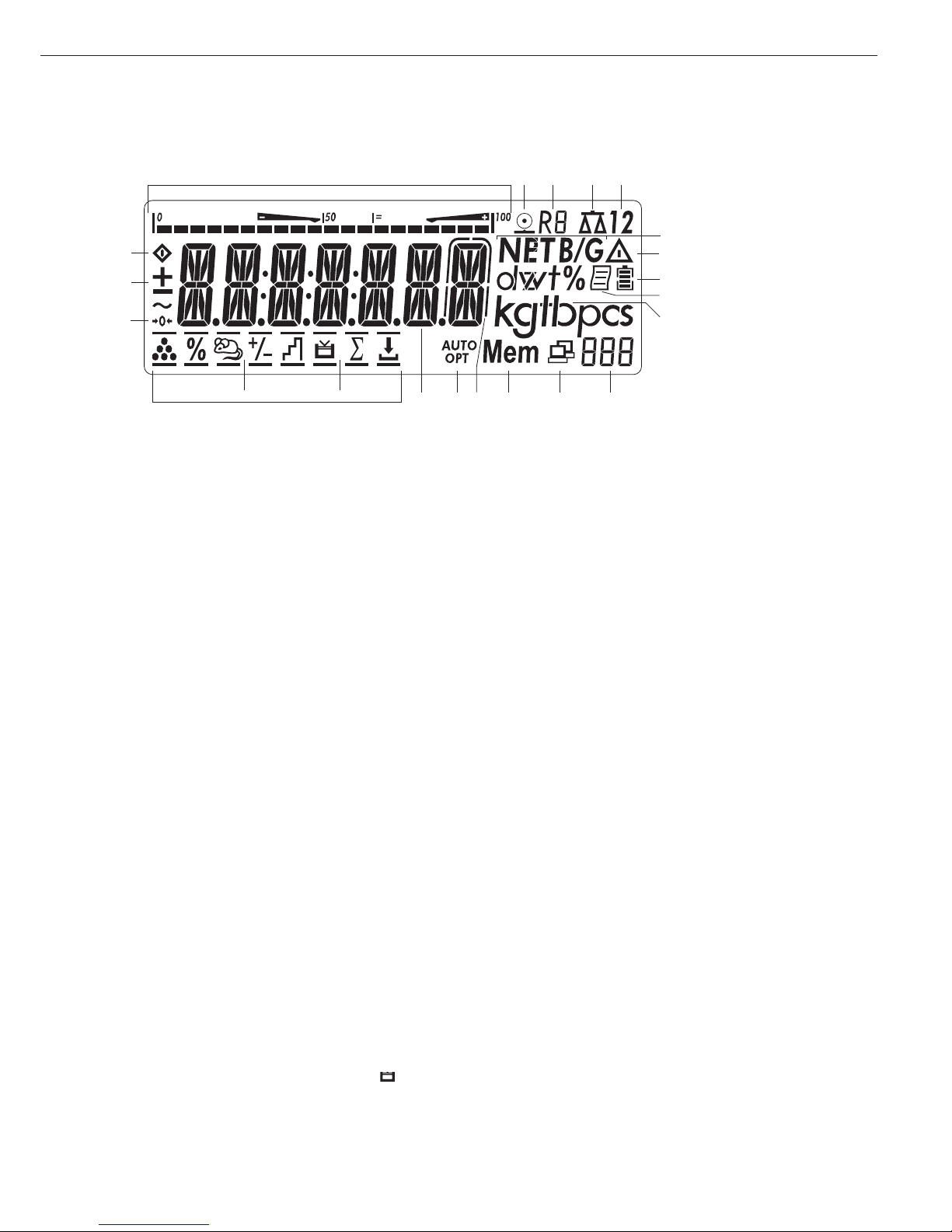
Display in Weighing Mode
The illustration above depicts all of the
main display elements and symbols that
can be shown during weighing.
1. Bar graph
– Shows the percentage of the
weighing platform’s capacity that is
“used up” by the load on the scale
(gross value), or
– Shows the measured value in
relation to a target value (with the
Checkweighing or Classification
application)
2. Printing in progress
3. Display of the range on multiple-range
instruments
4. Indicates active weighing platform;
flashes to prompt calibration/
adjustment
5. Selected weighing platform (1 or 2)
6. Indicates whether the value on the
main display is net or gross
(with tare in memory or preset tare)
7. Identifies the value on the main display
as calculated (value not valid in legal
metrology)
8. Battery symbol showing status of
rechargeable battery (empty outline
indicates battery is drained)
9. GMP-compliant printing in progress
(Signum 2 and 3 only)
10. Weight unit of the value displayed
Signum 2 and 3 only:
11. Numeric display; e.g., showing
reference value
Signum 2 and 3 only:
12. Symbol indicating data transfer:
– Interface initialized
– Flashes during data transfer
13. Symbol for product data memory
14. In legal metrology, on equipment
with e = d, the digit shown with
a border is d < e.
15. Auto or opt (Signum 2 and 3 only):
– Auto: Depending on the weight
value, a reaction is triggered
in the application
– Opt: Reference sample value is
being updated (optimized)
automatically (Counting
application)
16. Weight value or calculated value
(main display)
17. Application symbols for applications
in Signum 2 and 3:
Application 1:
A Counting
B Weighing in Percent
V Averaging (Animal Weighing)
Application 2:
H Checkweighing
W Classification
Checkweighing: Batching to a
Target Value
Application 3:
L Totalizing
M Net-total Formulation
Verified models only:
18. The zero-setting symbol is displayed
after the active scale or weighing
platform has been zeroed (indicates
that the deviation from zero is equal or
less than 0.25 e)
19. Plus or minus sign for the value
displayed
20. Busy symbol; indicates that an internal
process is in progress
Saving Data in Weighing Mode
All of the application parameters saved
(e.g., reference values) remain in
memory and are still available after
– the Signum has been switched off
– you return to the originally selected
application from a second one (e.g.,
when you switch from Averaging back
to Counting, all parameters saved
for Counting are available)
13
4
5
6
7
8
9
10
11
12131415
16
17
18
19
20
Appl. 1 Appl. 2 Appl. 3
2
Configuration
(Operating Menu)
The keys below the readout let you
navigate the menu and define parameters
for configuration.
Opening the Menu
Press the e key to switch the Signum off
and then on again; while all segments are
displayed, press the ) key briefly.
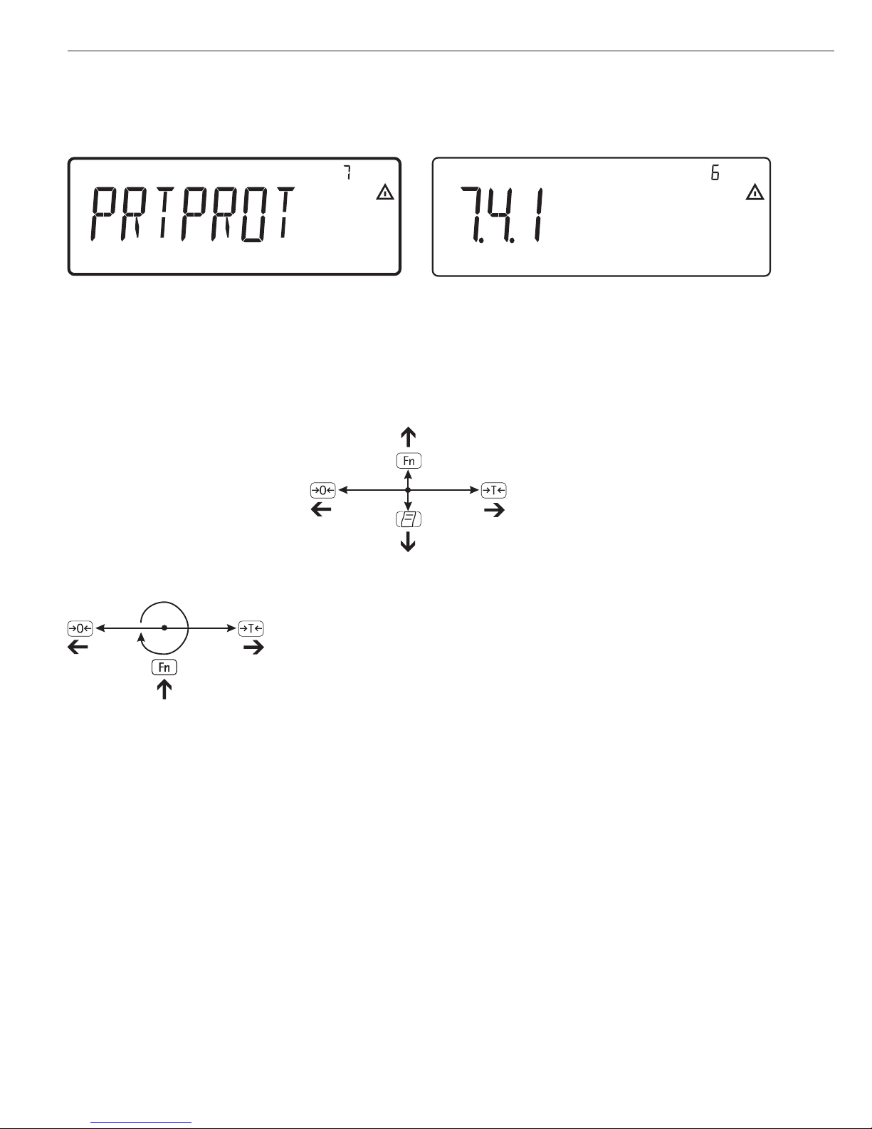
Navigating the Menu
( Close the active submenu and
return to the next higher menu level
(“back”)
) – Press briefly:
Select and save a menu item
– Press and hold (> 2 seconds):
Exit the menu
k Show the next item on the same
menu level (the display scrolls
through all items in series)
p Print the menu settings starting
from the current position, or print
Info data
Alphanumeric Input in the Menu
( – Press briefly:
Activate character to the left
of the currently active character
(when first character is active:
exit the input mode without
saving changes)
– Press and hold (> 2 seconds):
Exit the input mode without
saving changes
) – Press briefly:
Confirm currently active
character and move 1 position
to the right (after the last
character: save input)
– Press and hold (> 2 seconds):
Save current input and display
the menu item
k – Cursor in first position,
no characters entered yet:
Delete character(s) and enter 0
– Change the displayed character;
scroll forward (sequence:
0 through 9, decimal point,
minus sign, A through Z, space)
p – Cursor in first position,
no characters entered yet: Delete
entire string and enter a space
– Change the displayed character;
scroll backwards (sequence:
Space, Z through A, minus sign,
decimal point, 9 through 0)
Numeric input in Signum 3 operating
menu:
Enter values (date and time, etc.) using
the 10-key numeric keypad
Saving Menu Settings
The parameters selected in the operating
menu remain saved after you switch off
the Signum.
You can prevent unauthorized changes
in operating menu settings by requiring
password input for menu access.
Operating Design
14
Display of menu settings: Text menu (example) Display of menu settings: Numeric menu (example)

15
Errors
– If a key is inactive, “———-” or
“No function” is displayed briefly
(2 seconds) and an acoustic signal
(double-beep) is emitted
– Temporary errors are displayed for
2 seconds in the measured value/result
line (e.g.,
Inf 09); fatal errors (e.g.,
Err 101) can be cleared by switching
the scale off and then on again.
Error codes are described in detail
under “Error Codes” on page 90.
Data Output
Printer
You can connect two strip or label printers
to Signum 1, 2 or 3, and have printouts
generated at the press of a key or automatically. Printout formats are user-definable. You can also configure separate
summarized printouts, and print a list of
the active menu settings. See “Configuring
Printouts” on page 80 for details.
Digital Input/Output
Interface + Optional I/O
The digital I/O interface is supported
by the Checkweighing and Classification
applications.
Checkweighing
The output device has a number
of control functions. Four data outputs
transfer signals for “less than,” “equal to,”
“greater” and “set.” You can define
whether the outputs are always active or
are activated only at stability, only within
the checkweighing range, only within
the checkweighing range at stability, or
switched off.
Classification
Four data outputs transfer information on
the class of the load (Class 1, 2, 3, 4 or 5)
and indicate when the minimum load is
exceeded (Set). You can define whether
the outputs are always active, activated
only at stability, or off. For details,
see “Classification” on page 68.
COM Port
You can define a number of parameters
for this SBI and SMA interface (print command, time-dependent autoprint, ID
codes). See “Interface Port” on page 82 for
details.
Backup
Application parameters (such as reference
values) are saved when you change application programs or switch off the Signum.
You can assign a password to prevent
unauthorized users from changing settings
in the “Device parameters” menu under:
Setup
Password
See also page 18.
You can configure the Signum by
selecting parameters in the operating
menu. The parameters are combined
in the following groups (this is the
first menu level):
– Application parameters
– Fn key function
– Device parameters
– Device-specific information (“
Info”)
– Language
When used in legal metrology,
not all parameters can be accessed.
Factory-set parameters are identified by
an “*” in the list starting on page 19.
You can choose from five languages
for the display of information:
– German
– English (factory setting)
– English with U.S. date/time format
– French
– Italian
– Spanish
Printing parameter settings:
§ Open the operating menu and
press the p key
Scope of printout:
Depends on the active menu level
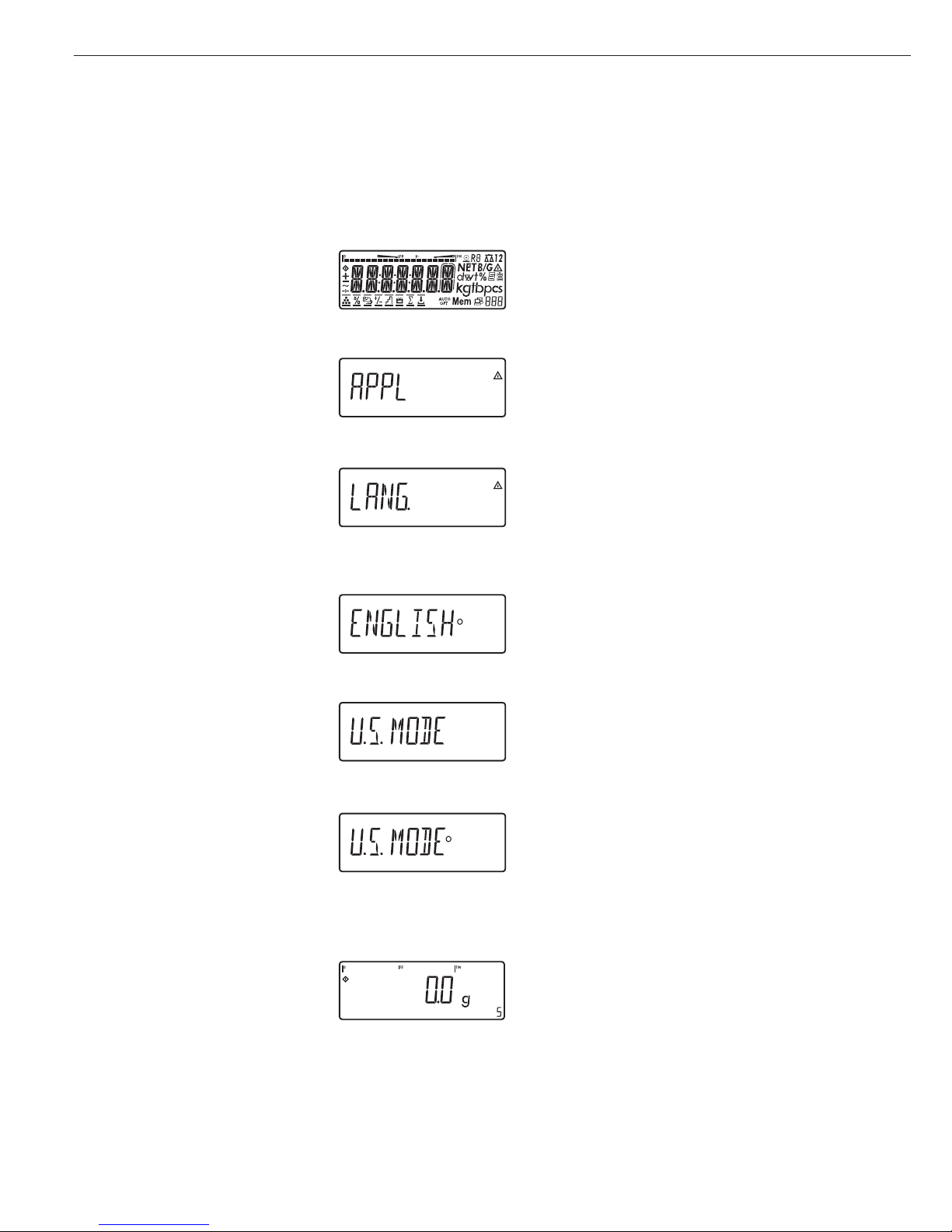
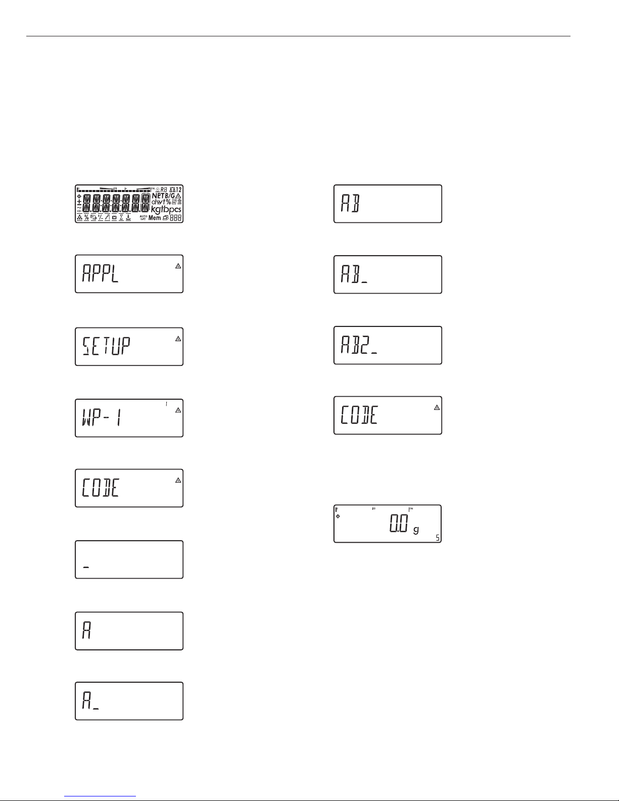
Setting the Language
Example: Selecting “U.S. Mode” for the language
e
Switch on the scale
)
While all segments are lit,
press the ) key
The first item in the main menu is shown:
APPL
k
Switch to the LANG. menu item (press
k repeatedly until
LANG. is shown)
)
Select LANG. to open the submenu for
setting the language
The currently active language setting is
shown
k
Press k repeatedly until U.S. Mode
is displayed
)
Confirm this menu item
(
Exit this menu level and configure
other settings as desired, or
)
(press and hold) Exit the operating menu
Configuration
16
17
Configuring a Password
Example:
Assign a password (in this example,
AB2) to protect the application program settings APPL
and the device parameters SETUP from unauthorized changes
e
1 Switch on the Signum
)
2 While all segments are lit,
press )
The first item in the main
menu is shown:
APPL
k
3 Select the SETUP menu
item (press k repeatedly
until
SETUP is displayed)
)
4 Open the SETUP menu
k
5 Select the PASSWORD menu
item (press k repeatedly
until
PASSWORD is displayed)
)
6 Open the PASSWORD menu
p, p
7 Enter the first character
using the p and k keys
(in this example:
a symbol
is shown on the readout)
)
8 Save the character
p, p, p
9 Enter the second character
using the p and k keys
(in this example:
B)
)
10 Save the character
k, k, k
, 11 Enter the third character
using the p and k keys
(in this example:
2)
)
12 Save the password
(
13 Exit this menu level
to configure other menu
settings, or
)
14 Exit the operating menu
(press and hold the ) key)
To delete a password:
Overwrite the old password
with the new password, or enter
a space as the password and
press ) to confirm
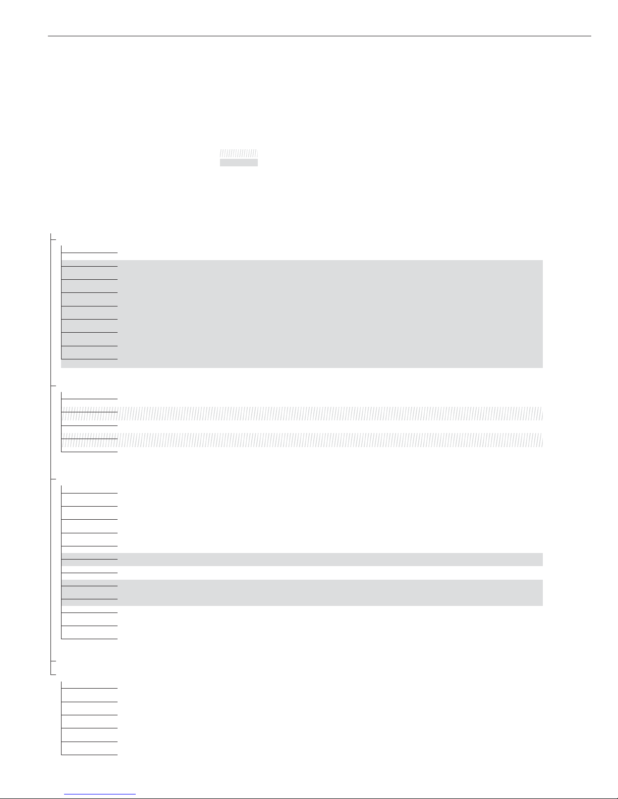
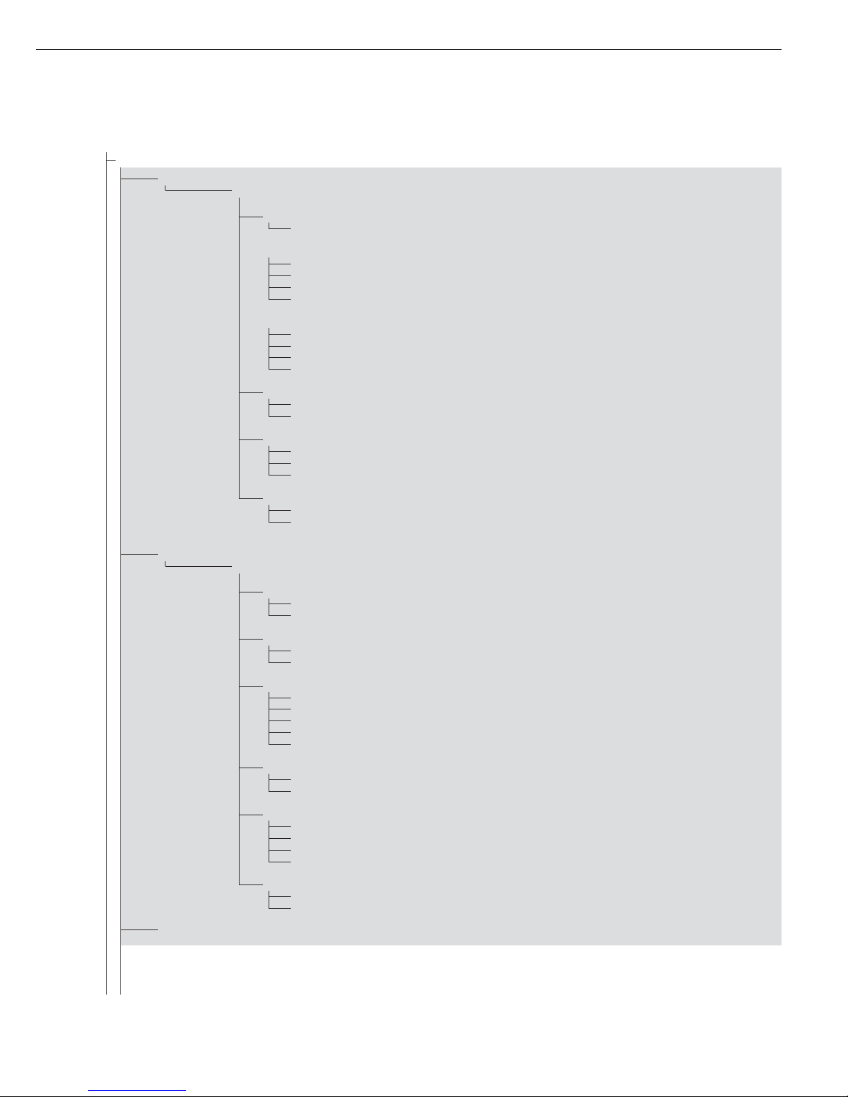
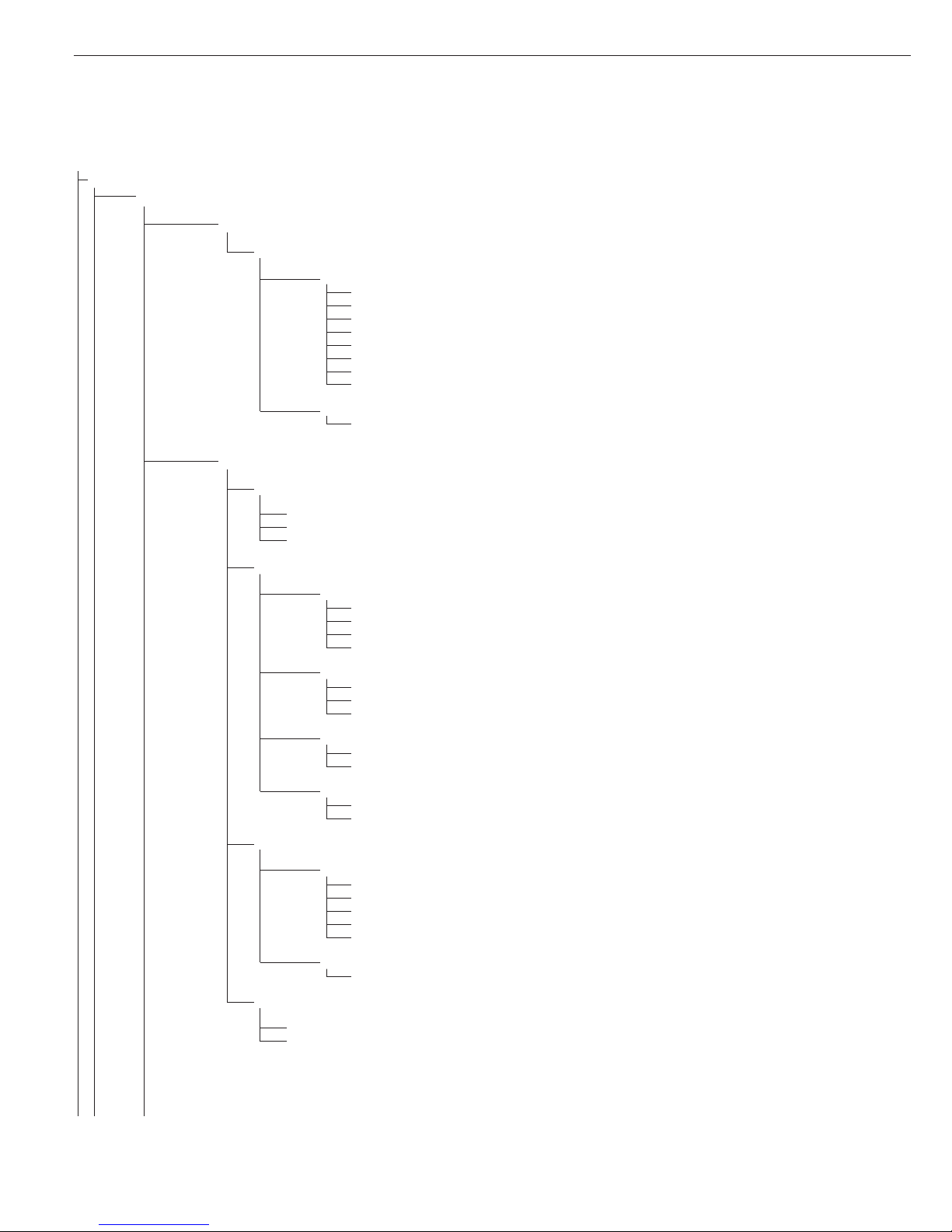
1stlevel 2ndlevel Function
display display
Menu
appl Select and configure application programs
weigh. Basic weighing function
count. Counting
neutr.m Neutral measurement
anim.wg Averaging (animal weighing)
check.wg Checkweighing
clss. Classification
perc.wg Weighing in percent
net tot Net-total formulation
totaliz Totalizing
Fn-Key Define the function of the k key
off No function
gro net Gross/net toggling (Signum 1 only)
2.unit Show 2
nd
weight unit
res 10 10-fold increased resolution (Signum 1 only)
SQmin Show the minimum permissible sample quantity
Setup Adapt Signum to user requirements
wp1 Settings for weighing instrument on WP1
com1 Settings for the RS-232 interface
UNICOM Settings for the optional second interface
comspec Reference weigher connection: configure the A/D converter (optional)
ctrl IO Set the function of the universal input (control line)
barcode Set the bar code scanner function
prtprot Configure the printout
Utilit Operating parameters
time Set the time
Date Set the date
password Enter a password to protect menu settings
SQmin User options: – Display minimum permissible sample quantity
– Include SQmin in GLP printout
Info View device-specific information (service date, serial number, etc.)
Lang Select language for calibration, adjustment and GMP printouts
deutsch German
english English
u.s. mode English with U.S. date/time format
franc. French
ital. Italian
espanol Spanish
Operating Menu Overview
You can configure the Signum to meet
individual requirements by entering
user data and setting selected parameters
in the operating menu.
Menu levels are identified by texts, and numeric codes identify the individual settings.
= Setting/function available in Signum 1 only
= Setting/function available in Signum 2 and 3 only
Configuration
18
19
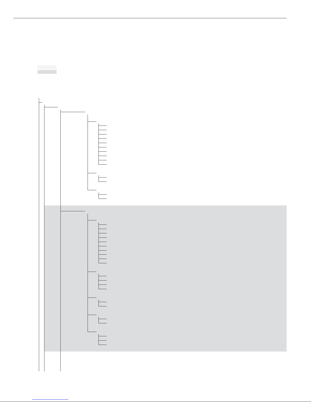
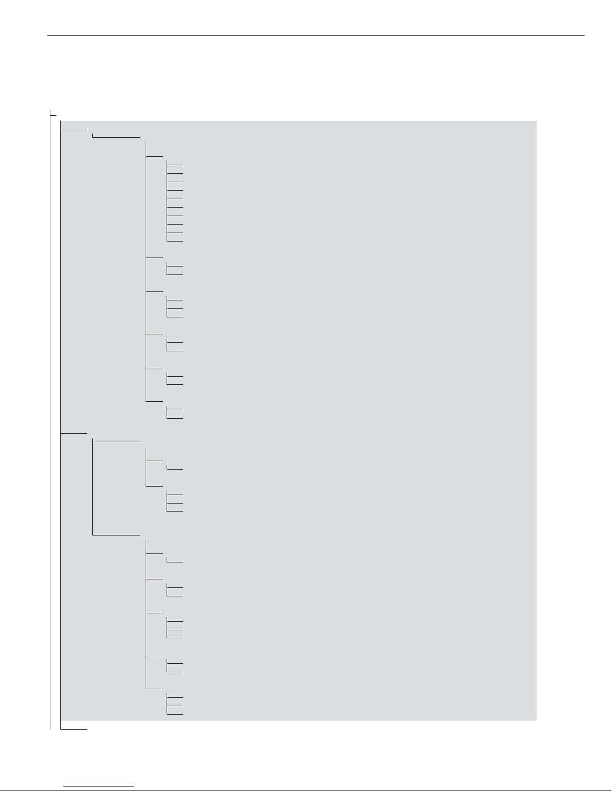
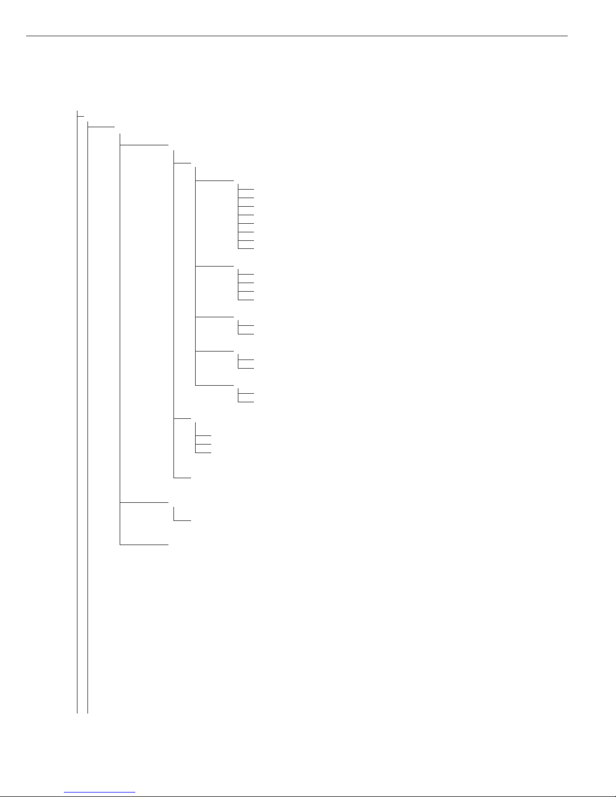
Operating Menu
= Setting/function available in Signum 1 only
= Setting/function available in Signum 2 and Signum 3 only
* Factory setting
Menu
appl Application programs
appl1**
weigh.
Basic Weighing Function
3.5. Minimum load for automatic taring and automatic printing
3.5.1* 1 digit
3.5.2 2 digits
3.5.3 5 digits
3.5.4 10 digits
3.5.5 20 digits
3.5.6 50 digits
3.5.7 100 digits
3.5.8 200 digits
3.5.9 500 digits
3.5.10 1000 digits
3.7. Automatic taring: first weight tared
3.7.1* Off
3.7.2 On
9.1. Factory settings for all application programs
9.1.1 Yes
9.1.2* No
count. Counting
3.6. Minimum load for initialization
3.6.1* 1 digit
3.6.2 2 digits
3.6.3 5 digits
3.6.4 10 digits
3.6.5 20 digits
3.6.6 50 digits
3.6.7 100 digits
3.6.8 200 digits
3.6.9 500 digits
3.6.10 1000 digits
3.9. Resolution for calculation of reference value
3.9.1* Display resolution
3.9.2 Display resolution + 1 decimal place
3.9.3 Display resolution + 2 decimal places
3.9.4 Internal resolution
3.11. Parameter for saving weight (“storage parameter”)
3.11.1* At stability
3.11.2 At increased stability
3.12. Reference sample updating (“APW update”)
3.12.1 Off
3.12.3* Automatic
3.13. Reference weighing instrument
3.13.1* No reference instrument selected
3.13.2 Weighing platform WP 1
3.13.3 Weighing platform WP 2
** Menu level used in Signum 3 only
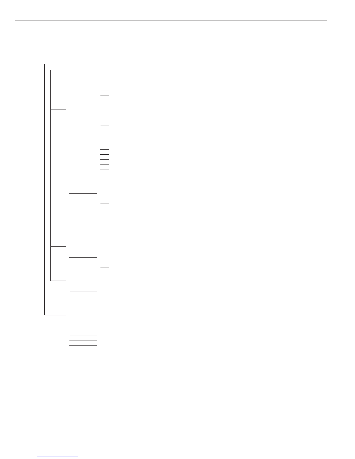
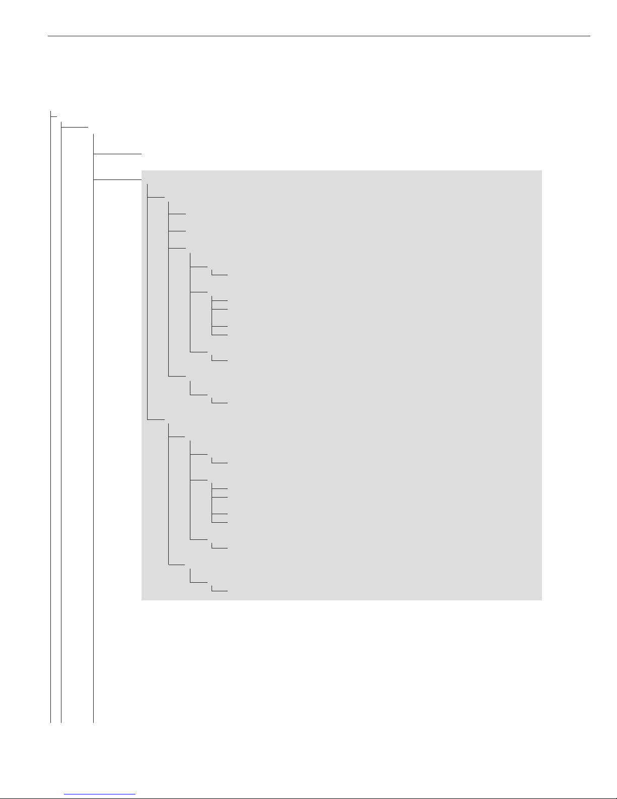
appl
appl 1**
neutr.m
Neutral Measurement
3.6. Minimum load for initialization
Numeric menu as for Counting
3.9. Resolution for calculation of reference value
3.9.1* Display resolution
3.9.2 Display resolution + 1 decimal place
3.9.3 Display resolution + 2 decimal places
3.9.4 Internal resolution
3.10. Decimal places in displayed result
3.10.1 * None
3.10.2 1 decimal place
3.10.3 2 decimal places
3.10.4 3 decimal places
3.11. Parameter for saving weight
3.11.1* At stability
3.11.2 At increased stability
3.13. Reference weighing instrument
3.13.1* Off
3.13.2 To weighing platform WP1
3.13.3 To weighing platform WP2
anim.wg Averaging (Animal Weighing)
3.6. Minimum load for automatic start
Numeric menu as for Counting
3.18. Start of averaging routine
3.18.1* Manual
3.18.2 Automatic
3.19. Averaging
3.19.1 0.1 % of the animal/object
3.19.2* 0.2% of the animal/object
3.19.3 0.5 % of the animal/object
3.19.4 1% of the animal/object
3.19.5 2% of the animal/object
3.19.6 5% of the animal/object
3.19.7 10% of the animal/object
3.19.8 20% of the animal/object
3.19.9 50% of the animal/object
3.19.10 100 % of the animal/object
3.20. Automatic printout of results
3.20.1* Off
3.20.2 On
3.21. Static display of result after load removed
3.21.1* Display is static until unload threshold reached
3.21.2 Display is static until c is pressed
* Factory setting
** Menu level used in Signum 3 only
Configuration
20
21
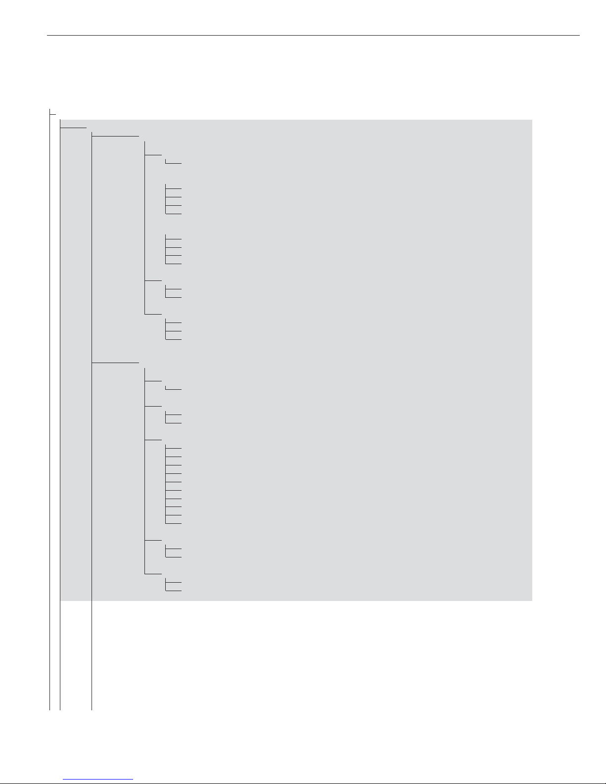
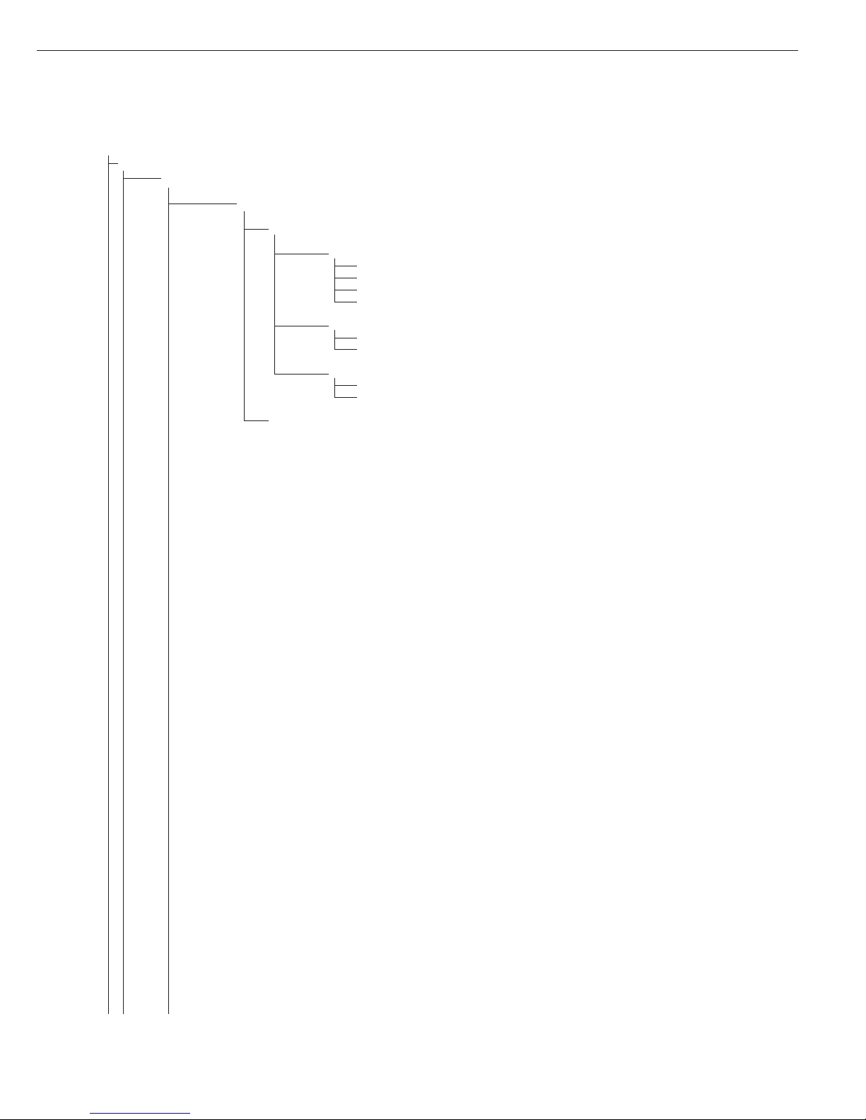
appl
appl 1**
perc.wg
Weighing in Percent
3.6. Minimum load for saving initialization
Numeric menu as for Counting
3.9. Resolution for calculation of reference value
3.9.1* Display resolution
3.9.2 Display resolution + 1 decimal place
3.9.3 Display resolution + 2 decimal places
3.9.4 Internal resolution
3.10. Decimal places in displayed result
3.10.1* None
3.10.2 1 decimal place
3.10.3 2 decimal places
3.10.4 3 decimal places
3.11. Parameter for saving weight
3.11.1* At stability
3.11.2 At increased stability
3.13. Reference weighing instrument
3.13.1* Off
3.13.2 To weighing platform WP1
3.13.3 To weighing platform WP2
3.15. Display of calculated value
3.15.1* Residue
3.15.2 Loss
Appl 2**
check.wg Checkweighing
4.2. Checkweighing range
4.2.1* 30 to 170%
4.2.2 10% to infinity
4.3. Activate control line for “Set” as:
4.3.1* “Set” output
4.3.2 Ready to operate (for process control systems)
4.4. Activation of outputs
4.4.1 Off
4.4.2 Always active
4.4.3 Active at stability
4.4.4* Active within checkweighing range
4.4.5 Active at stability within the checkweighing range
4.5. Parameter input
4.5.1* Min, max, target
4.5.2 Only target with percent limits
4.6. Automatic printing
4.6.1* Off
4.6.2 On
4.6.3 Only values within tolerance
4.6.4 Only values outside tolerance
4.7. Checkweighing toward zero
4.7.1* Off
4.7.2 On
Off Disabled
* Factory setting
** Menu level used in Signum 3 only
Appl
Appl 2**
class.
Classification
3.6. Minimum load for initialization and defining the class 1 lower limit
3.6.1* 1 digit
3.6.2 2 digits
3.6.3 5 digits
3.6.4 10 digits
3.6.5 20 digits
3.6.6 50 digits
3.6.7 100 digits
3.6.8 200 digits
3.6.9 500 digits
3.6.10 1000 digits
4.3. Activate control line for “Set” as:
4.3.1* “Set” output
4.3.2 Ready to operate (for process control systems)
4.7. Activation of outputs
4.7.1 Off
4.7.2 Always active
4.7.3* Active at stability
4.8. Number of classes
4.8.1* 3 classes
4.8.2 5 classes
4.9. Parameter input
4.9.1* Weight values
4.9.2 Percentage
4.10. Automatic printing
4.10.1* Off
4.10.2 On
Appl 3**
net tot Net-total Formulation (Second Tare Memory)
3.6. Minimum load for automatically saving/transferring values
Numeric menu as for Counting
3.17. Printout when value is saved in totalizing memory
3.17.1 Automatic printout of results off
3.17.2* Generate printout with complete standard configuration each time O is pressed
3.17.3 Generate printout with complete standard configuration only once when O is pressed
totaliz Totalizing
3.6. Minimum load for automatically saving/transferring values
Numeric menu as for Counting
3.16. Values saved automatically
3.16.1* Off
3.16.2 On
3.17. Printout when value is saved in totalizing memory
3.17.1 Automatic printout of results off
3.17.2* Individual of transaction by pressing O
3.17.3 Print components of transaction by pressing O
3.22. Source of data for values saved automatically
3.22.1* Application 1
3.22.2 Application 2
3.23. Value(s) to be saved
3.23.1* Net
3.23.2 Calculated
3.23.3 Net and calculated
oFF Disabled
* Factory setting ** Menu level used in Signum 3 only
Configuration
22
23
appl
a.tare
3.7. Autom. taring: first weight tared
3.7.1* Off
3.7.2 On
m.weigh
3.5. Minimum load for automatic taring and automatic printing
3.5.1 * 1 digit
3.5.2 2 digits
3.5.3 5 digits
3.5.4 10 digits
3.5.5 20 digits
3.5.6 50 digits
3.5.7 100 digits
3.5.8 200 digits
3.5.9 500 digits
3.5.10 1000 digits
a.start
3.8. Start application with most recent application data when Signum is switched on
3.8.1 Automatic (on)
3.8.2* Manual (off)
sel.cf
3.24. Selective deleting with the c key
3.24.1* Clear all application data
3.24.2 Clear only selected applications
Tare F.
3.25. Tare function
3.25.1 Add input value (weight value) for taring
3.25.2 Tare value can be overwritten
def.app
9.1. Factory settings for all application programs
9.1.1 Yes
9.1.2* No
fn-key k Key Assignment
off * No k key function
gro net Signum 1 only: Gross/net toggling
2. unit Show 2nd Weight unit
res 10 Signum 1 only: 10-fold increased resolution Display: max. 10 seconds
SQmin Show the minimum permissible sample quantity
* Factory setting

Setup Device Parameters
Password prompt displayed if a password is configured
wp-1
1
Weighing platform 1
(Display designation of this menu level: 1)
1.1. Adapt weighing instrument to ambient conditions (adapt filter)
1.1.1 Very stable conditions
1.1.2* Stable conditions
1.1.3 Unstable conditions
1.1.4 Very unstable conditions
1.2. Application filter
1.2.1* Final readout
1.2.2 Filling mode
1.2.3 Low filtering
1.2.4 Without filtering
1.3. Stability range
1.3.1 4 digit
1.3.2 1 digit
1.3.3 1 digit
1)
1.3.4* 2 digits
1)
1.3.5 4 digits
1)
1.3.6 8 digits
1)
1.4. Stability symbol delay
1.4.1 No delay
1.4.2* Short delay
1.4.3 Average delay
1.4.4 Long delay
1.5. Taring
1)
1.5.1 Without stability
1.5.2* After stability
1.6. Auto zero
1.6.1* On
1.6.2 Off
1.7. Weight Unit 1
2)
1.7.1 Grams / o
1.7.2 Grams / g
1.7.3* Kilograms / kg
1.7.4 Carats / ct
1)
1.7.5 Pounds / lb
1)
1.7.6 Ounces / oz
1)
1.7.7 Troy ounces / ozt
1)
1.7.8 Hong Kong taels / tlh
1)
1.7.9 Singapore taels / tls
1)
1.7.10 Taiwanese taels / tlt
1)
1.7.11 Grains /GN
1)
1.7.12 Pennyweights / dwt
1)
1.7.14 Parts per pound / lb
1)
1.7.15 Chinese taels / tlc
1)
1.7.16 Mommes / mom
1)
1.7.17 Austrian carats / k
1)
1.7.18 Tola / tol
1)
1.7.19 Baht / bat
1)
1.7.20 Mesghal / MS
1)
1.7.21 Tons / t
1.7.22 Pounds:ounces (lb:oz)
1.8. Display accuracy 1
1.8.1* All digits
1.8.2 Reduced by 1 decimal place for load change
1.8.14 10-fold increased resolution
1.8.15 Resolution increased by 2 scale intervals (e.g., 5 g to 1 g)
1.8.16 Resolution increased by 1 scale interval
(e.g., from 2 g to 1 g or from 10 g to 5 g)
1)
Not available on instruments verified for use in legal metrology
2)
Depends on weighing platform model
* Factory setting
Configuration
24

25
Setup
wp-1
1
1.9. Calibration and adjustment
1.9.1* External calibration/adjustment; default weight
1.9.3 External calibration/adjustment; weight can be selected under menu item 1.18.1
1.9.4 Internal calibration/adjustment (models with built-in motorized calibration weight only)
1.9.8 Set preload
1.9.9 Clear preload
1.9.10 No function when you press the J key
1.10. Calibration/adjustment sequence
1.10.1 Calibration with automatic adjustment
1.10.2* Calibration with adjustment triggered manually
1.11. Zero-setting range
1.11.1 1 percent/max. cap.
1.11.2* 2 percent/max.cap.
1.12. Initial zero-setting range
1.12.1* Factory setting (depends on model)
1.12.2 2 percent/max. cap.
1.12.3 5 percent/max.cap. (setting depends on model)
1.13. Tare/zero at power on
1.13.1* On
1.13.2 Off, load previous tare value
1.13.3 Only zero at power on
1.15. Calibration prompt
1.15.1* Off
1.15.2 Calibration prompt (W) flashes on the display
1.16. External calibration/adjustment
1)
1.16.1* Accessible
1.16.2
2)
Blocked
1.17. Calibration weight unit
1.17.1 Grams
1.17.2* Kilograms
1.17.3 Pounds
1)
1.18. Enter calibration weight
1.18.1 External user-defined weight (enter value; e.g.: 10,000 kg)
3.1. Weight unit 2
3)
3.1.1 Grams / o
3.1.2 Grams / g
3.1.3* Kilograms / kg
3.1.4 Carats /ct
1)
3.1.5 Pounds /lb
1)
3.1.6 Ounces /oz
1)
3.1.7 Troy ounces / ozt
1)
3.1.8 Hong Kong taels / tlh
1)
3.1.9 Singapore taels / tls
1)
3.1.10 Taiwanese taels / tlt
1)
3.1.11 Grains / GN
1)
3.1.12 Pennyweights / dwt
1)
3.1.14 Parts per pound / lb
1)
3.1.15 Chinese taels / tlc
1)
3.1.16 Mommes / mom
1)
3.1.17 Austrian carats /k
1)
3.1.18 Tola / tol
1)
3.1.19 Baht / bat
1)
3.1.20 Mesghal / MS
1)
3.1.21 Tons / t
3.1.22 Pounds:ounces (lb:oz)
3.2. Display accuracy 2
3.2.1* All digits
3.2.2 Reduced by 1 decimal place for load change
3.2.14 10-fold increased resolution
3.2.15 Resolution increased by 2 scale intervals (e.g., 5 g to 1 g)
3.2.16 Resolution increased by 1 scale interval (e.g., from 2 g to 1 g or from 10 g to 5 g)
3.3. Weight unit 3
3)
(settings as for 3.1, “Weight unit 2”)
3.4. Display accuracy
3)
(settings as for 3.2, “Display accuracy 2”)
9.1. Restore factory settings in WP1 numeric menu
9.1.1 Yes
9.1.2* No
1)
= Not available on instruments verified for use in legal metrology
2)
= Factory setting on instrument verified for use in legal metrology
3)
= Menu depends on weighing platform model
* Factory setting

Setup
Com1
2
Interface port 1
(Display designation of this menu level: 2)
off
*
Off
WP2 Weighing platform 2
rs-232
*
RS-232
sbi-std SBI standard version
sbi-app SBI trade version (for legal metrology)
bpi-232
*
XBPI-232
1)
1.1. through 1.8.
Numeric menu as for WP1
1.9. Calibration and adjustment
1.9.1* External calibration/adjustment; default weight
1.9.3 External calibration/adjustment;
weight can be selected under menu item 1.18.1
1.9.4 Internal calibration/adjustment
1.9.10 No function when you press and hold J > 2 sec
1.10. through 9.1.
Numeric menu as for WP1
adc-232 ADC-232
1)
1.1. through 9.1.
Numeric menu as for WP1
datprot Data protocol
sbi
*
SBI: standard version
5.1. Baud rate
5.1.1 150 baud
5.1.2 300 baud
5.1.3 600 baud
5.1.4* 1200 baud
5.1.5 2400 baud
5.1.6 4800 baud
5.1.7 9600 baud
5.1.8 19,200 baud
5.2. Parity
5.2.2 Space
2)
5.2.3* Odd
5.2.4 Even
5.2.5 None
3)
5.3. Number of stop bits
5.3.1* 1 stop bit
5.3.2 2 stop bits
5.4. Handshake mode
5.4.1 Software handshake
5.4.3* Hardware handshake, 1 character after CTS
5.6. Number of data bits
5.6.1* 7 data bits
5.6.2 8 data bits
6.1. Data output: manual/automatic
6.1.1 Manual without stability
6.1.2* Manual after stability
6.1.4 Automatic without stability
6.1.5 Automatic with stability
6.1.7 Protocol for computer (PC)
1)
Menu depends on weighing platform model
2)
not with setting 5.6.2 (8 bits)
3)
not with setting 5.6.1 (7 bits)
* Factory setting
Configuration
26
27
Setup
Com1
2
datProt
sbi
*
6.3. Time-dependent automatic data output
6.3.1* 1 display update
6.3.2 2 display updates
6.3.4 10 display updates
6.3.7 100 display updates
7.2. Data output: line format for printout
7.2.1 For raw data: 16 characters
7.2.2* For other applications: 22 characters
9.1. Restore factory settings in numeric menu COM1: SBI
9.1.1 Yes
9.1.2* No
bpi-232 XBPI-232
* Factory setting
Setup
Com1
2
datProt
SMA SMA interface function
5.1. Baud rate
5.1.1 150 baud
5.1.2 300 baud
5.1.3 600 baud
5.1.4 1200 baud
5.1.5 2400 baud
5.1.6 4800 baud
5.1.7* 9600 baud
5.1.8 19,200 baud
5.2. through 5.6.
Numeric menu as for SBI
Printer Printer configuration
YDP01IS YDP01IS
line
*
Strip printer
label Label printer
lab ff Label printer with manual feed
YDP02 YDP02 variants
5.1. Baud rate
5.1.4* 1200 baud
5.1.5 2400 baud
5.1.6 4800 baud
5.1.7 9600 baud
5.2. Parity
5.2.2 Space
5.2.3* Odd
5.2.4 Even
5.3. Number of stop bits
5.3.1* 1 stop bit
5.3.2 2 stop bits
5.4. Handshake mode
5.4.1 Software handshake
5.4.3* Hardware handshake, 1 character after CTS
YDP03 YDP03-0CE
5.1. Baud rate
5.1.4* 1200 baud
5.1.5 2400 baud
5.1.6 4800 baud
5.1.7 9600 baud
5.1.8 19,200 baud
5.2. through 5.4.
Numeric menu as for YDP02
YDP02IS YDP02IS
line
*
Strip printer
label Label printer
* Factory setting
Configuration
28
29
Setup
Com1
2
Printer
Uni-pri Universal interface
5.1. Baud rate
5.1.1 150 baud
5.1.2 300 baud
5.1.3 600 baud
5.1.4 1200 baud
5.1.5 2400 baud
5.1.6 4800 baud
5.1.7* 9600 baud
5.1.8 19,200 baud
5.2. Parity
5.2.2 Space
1)
5.2.3 Odd
5.2.4 Even
5.2.5* None
2)
5.3. Number of stop bits
5.3.1* 1 stop bit
5.3.2 2 stop bits
5.4. Handshake mode
5.4.1* Software handshake
5.4.3 Hardware handshake, 1 character after CTS
5.6. Number of data bits
5.6.1 7 data bits
5.6.2* 8 data bits
YDP04IS
*
YDP04IS
line
*
Strip printer
label Label printer
lab ff Label printer with manual feed
yam01is YAM01IS as electronic memory for print data
Memory Verifiable data memory
yam01is YAM01IS external data memory
oFF Off (disabled)
1)
not with setting 5.6.2 (8 bit)
2)
not with setting 5.6.1 (7 bits)
* Factory setting
Setup
unicom
3
Interface port 2 (Optional)
(Display designation of this menu level: 3)
off
*
Off
WP2 Weighing platform 2
rs-232 RS-232
sbi-std SBI standard version
sbi-app SBI trade version (for legal metrology)
bpi-232
*
XBPI-232
1)
1.1. through 1.8.
Numeric menu as for WP1
1.9. Calibration and Adjustment
1.9.1* External calibration/adjustment; default weight
1.9.3 External calibration/adjustment;
weight can be selected under menu item 1.18.1
1.9.4 Internal calibration/adjustment
1.9.10 No function when you press J
1.10. through 9.1.
Numeric menu as for WP1
adc-232 ADC-232
1)
1.1. through 9.1.
Numeric menu as for WP1
rs-485
*
RS-485
is-485
*
Connection of Sartorius IS weighing platform
1)
1.1. through 1.8.
Numeric menu as for WP1
1.9. Calibration and adjustment
1.9.1* External calibration/adjustment; default weight
1.9.3 External calibration/adjustment;
weight can be selected under menu item 1.18.1
1.9.4 Internal calibration/adjustment
1.9.10 No function when you press J
1.10. through 9.1.
Numeric menu as for WP1
adc-485 ADC-485
1)
1.1. through 9.1.
Numeric menu as for IS-485
* Factory setting
Configuration
30
 Loading...