

Page 1
Operating Instructions | Betriebsanleitung
Sartocheck® 4 plus Filter tester | Filter tester MultiUnit
Filter Integrity Tester | Filterintegritäts-Testgerät
1000025369
Page 2

2 Contents
Contents | Inhalt
English .............................................. Page 3
Deutsch ............................................. Seite 94
Page 3

1. Contents
1. Contents ........................................2
1.1 Contents ....................................3
1.2 FCC ......................................5
2. Overview and Proper Use .........................6
2.1 Overview .....................................6
2.2 Proper Use ...................................6
2.3 Technical Specifications ........................7
2.3.1 Dimensions and Weight ..................7
2.3.2 Connection Data .......................7
2.3.3 Pneumatics ............................7
2.3.4 Test Media .............................7
2.3.5 Product-specific Data ...................8
2.3.6 Test Methods ...........................9
2.3.7 General Data ...........................9
3. Safety ..........................................10
3.1 Notes | Warnings | Descriptions .................10
3.1.1 Manufacturer’s ID Label .................10
3.2 Installed Safety Equipment .....................11
3.3 Safety Precautions ............................11
3.4 Operator’s Obligations .........................12
3.5 Safety Tests and Inspections Carried Out by
the Manufacturer at the Facilities ................12
4. General Warnings ................................13
4.1 Hazards ......................................13
4.2 Operating Personnel and Service
and Maintenance Personnel .....................13
4.3 Installation of Replacement Parts ................14
4.4 Shutdown Procedure ..........................14
5. Installation ......................................15
5.1 Equipment Supplied ...........................15
5.2 Receipt of Delivery ............................15
5.3 Installation Instructions ........................16
5.3.1 Ambient Conditions and Conditions
at the Place of Installation ................16
5.3.2 Transport and Unpacking the Equipment ....16
5.4 Connections .................................17
5.4.1 Front Panel and Back Panel ..............17
5.4.2 Left and Right Panels ....................17
5.4.3 Left and Right Panels Sartocheck® 4
MultiUnit ..............................18
5.5 Connections with Internal Pressure Sensor .........18
5.6 Connections with External Pressure Sensor .........20
5.6.1 Inserting Paper Roll and Ribbon Cartridge . . .21
5.6.2 Sartocheck® 4 MultiUnit ..................22
6. Function ........................................23
6.1 General Functional Description .................23
6.2 Test Programs ................................23
6.3 Managing the Test Results .....................24
6.4 Function Test ................................24
6.5 Cleaning ....................................24
6.6 User Interrupt ...............................24
6.7 Self-Test for Broken Conductors and
Short-Circuiting ..............................24
6.8 Calibration ..................................24
6.9 Internal Pressure Sensor .......................24
6.10 Pressure Gauge Function .......................24
6.11 Cleaning | Drying .............................24
6.12 Safety Functions ..............................24
6.13 Software Update .............................25
6.14 Serial Number ................................25
7. Operation .......................................26
7.1 Switching on the Unit .........................26
7.1.1 Operating Elements .....................26
7.2 Switching the Unit ON and OFF .................28
7.2.1 Running a Test .........................29
7.2.2 Switching Off the Unit ..................29
7.2.3 Switching Off the Unit in the Event
of a Power Failure ......................29
7.3 Tests ........................................29
7.3.1 Test Parameters ........................29
7.3.2 Test Methods ..........................30
7.3.3 Programming Tests (F2 – Main Menu) .....30
7.4 Diffusion Test ................................31
7.5 Bubble Point Test .............................35
7.6 Customer-Specific BP .........................36
7.7 Diffusion and Bubble Point Test (Combined Test) . . .36
7.8 Water Intrusion Test | Water Flow Test . . . . . . . . . . .37
7.9 Pressure Drop Test ............................38
7.10 Multipoint Diffusion Test ......................38
7.11 Customer-Specific Multipoint Diffusion Test ......39
7.12 Volume Measurement .........................39
7.13 Plate Holder Test .............................40
7.14 Installed Bag Test .............................41
7.15 Program Database (F4 – Main Menu) ............42
7.15.1 Loading Test Program from Internal
Memory (F1) ...........................43
7.15.2 Uploading Test Program from SD card (F2) . .43
7.15.3 Saving Backup to SD card (F4) ............45
7.15.4 Loading Backup from SD card (F6) .........46
7.15.5 Deleting PLC Programs (F8). . . . . . . . . . . . . . .47
7.16 Visualize (F3 – Main Menu) ....................47
Contents 3
Page 4

4 Contents
7.17 Results Database (F5 – Main Menu) ...........47
7.18 Special Functions (F6 – Main Menu) ...........49
7.18.1 Function Test MU (F1) ................49
7.18.2 Function Test TU (F2) .................50
7.18.3 Cleaning (F3) . . . . . . . . . . . . . . . . . . . . . . . .50
7.18.4 Drying (F4) .........................52
7.18.5 Pressure Gauge Function (F5) ..........52
7.18.6 Modify Own Password (F6) ............53
7.19 Service (F7 – Main Menu) ....................53
7.19.1 Load Program from TU (F1-Service) .....54
7.19.1.1 External reference volume .....55
7.19.1.2 Network Settings .............56
7.19.1.3 Test Unit Address Allocation ....57
7.19.2 Hardware Configuration (F2-Service) ....58
7.19.3 Calibration|Adjustment (F3-Service) . . . .62
7.19.3.1 Calibration and Adjustment of
the Internal Pressure Sensor . . . .63
7.19.3.2 Calibration and Adjustment
of the External Pressure Sensor
Input .......................65
7.19.4 User Data Management (F4-Service) . . . .66
7.20 Using the Barcode Scanners (optional) .........67
8. Maintenance | Servicing ........................68
8.1 Maintenance ..............................68
8.1.1 Exchanging the Fine-wire Fuses ........68
8.1.2 Sartorius Stedim Biotech Service Menu . .68
8.2 Cleaning .................................68
9. Troubleshooting ................................69
9.1 Disposal and repair instructions ..............69
9.2 Troubleshooting ...........................69
10. Emergencies ...................................80
11. Information and Instructions on Disposal
and Repairs ...................................80
12. Appendix ......................................81
12.1 Detailed Test Description ....................81
12.1.1 Diffusion Test
(Only valid for the
Sartocheck
®
4 plus Filter tester) ........81
12.1.2 Bubble Point Test
(Only valid for the
Sartocheck® 4 plus Filter tester) ........82
12.1.3 Pressure Drop Test ...................83
12.1.4 Plate Holder Test .....................83
13. Electronic Data Transfer via Network Connection ..84
13.1 Network Concept ..........................84
13.2 FTP Server Requirements ....................85
13.2.1 How to Configure Your FTP Server ......85
14. PLC Control ...................................86
14.1 Digital Inputs ..............................86
14.1.1 START Input .........................86
14.1.2 PROG Input .........................86
14.1.3 STOP Input ..........................86
14.2 Digital Output .............................86
14.2.1 POWER on ..........................86
14.2.2 TEST RUNNING ......................86
14.2.3 ERROR .............................86
14.2.4 TEST OK ............................86
14.2.5 TEST not OK .........................86
14.2.6 External Valve 1. . . . . . . . . . . . . . . . . . . . . .86
14.2.7 External Valve 2. . . . . . . . . . . . . . . . . . . . . .86
14.3 Pin Layout ................................87
14.4 Examples .................................88
14.5 Outlets ...................................91
15. Index .........................................92
Page 5

1.2 FCC Note:
This equipment has been tested and found to comply with the limits for a Class B
digital device, pursuant to part 15 of the FCC Rules. These limits are designed
to provide reasonable protection against harmful interference in a residential
installation. This equipment generates, uses and can radiate radio frequency energy
and, if not installed and used in accordance with the instructions, may cause
harmful interference to radio communications. However, there is no guarantee that
interference will not occur in a particular installation. If this equipment does cause
harmful interference to radio or television reception, which can be determined
by turning the equipment off and on, the user is encouraged to try to correct the
interference using one or more of the following measures:
– Reorient or relocate the receiving antenna.
– Increase the separation between the equipment and receiver.
– Connect the equipment to an outlet on a circuit different from that
to which the receiver is connected.
– Consult the dealer or an experienced radio | TV technician for help.
Shielded Cables
Connections between the devices and peripherials must be made using shielded
cables in order to maintain compliance with FCC radio frequency emission limits.
Modifications
Any modifications made to this device that are not approved by Sartorius Stedim
Biotech GmbH may void the authority granted to the user by the FCC to operate
this equipment.
This instruction manual is based on screen shots from software version 3.1.3.
It is also valid for later software versions.
Translation
When the unit is supplied to countries in the EEA, the operating instructions must be
translated into the language or languages of the country of use. If any discrepancies
arise in the translated text, the original German operating instructions shall form the
basis for clearer interpretation or the manufacturer must be contacted.
Copyright
Reproduction, dissemination, transfer by any means and other use is not permitted
without the prior written consent of Sartorius Stedim Biotech GmbH. Offenders will
be liable for damages. All rights reserved.
Contents 5
Page 6
2. Overview and Proper Use 2. Overview and Proper Use
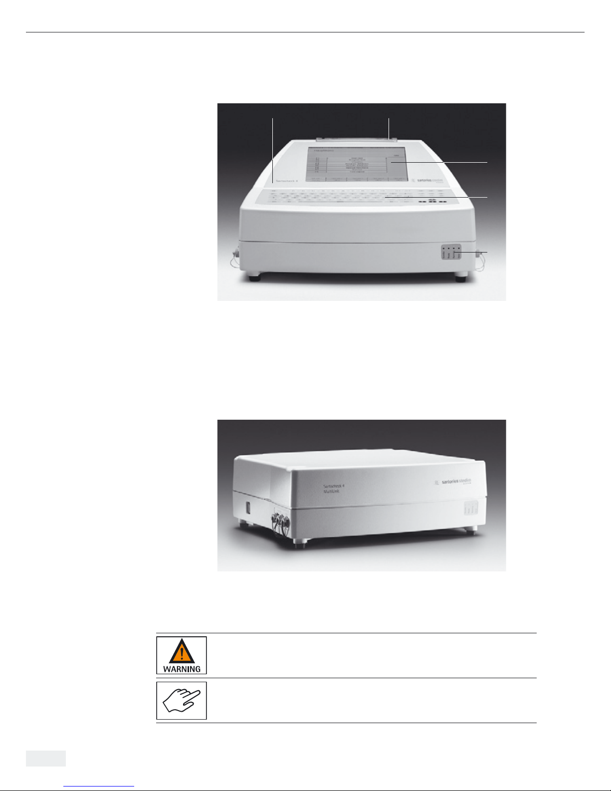
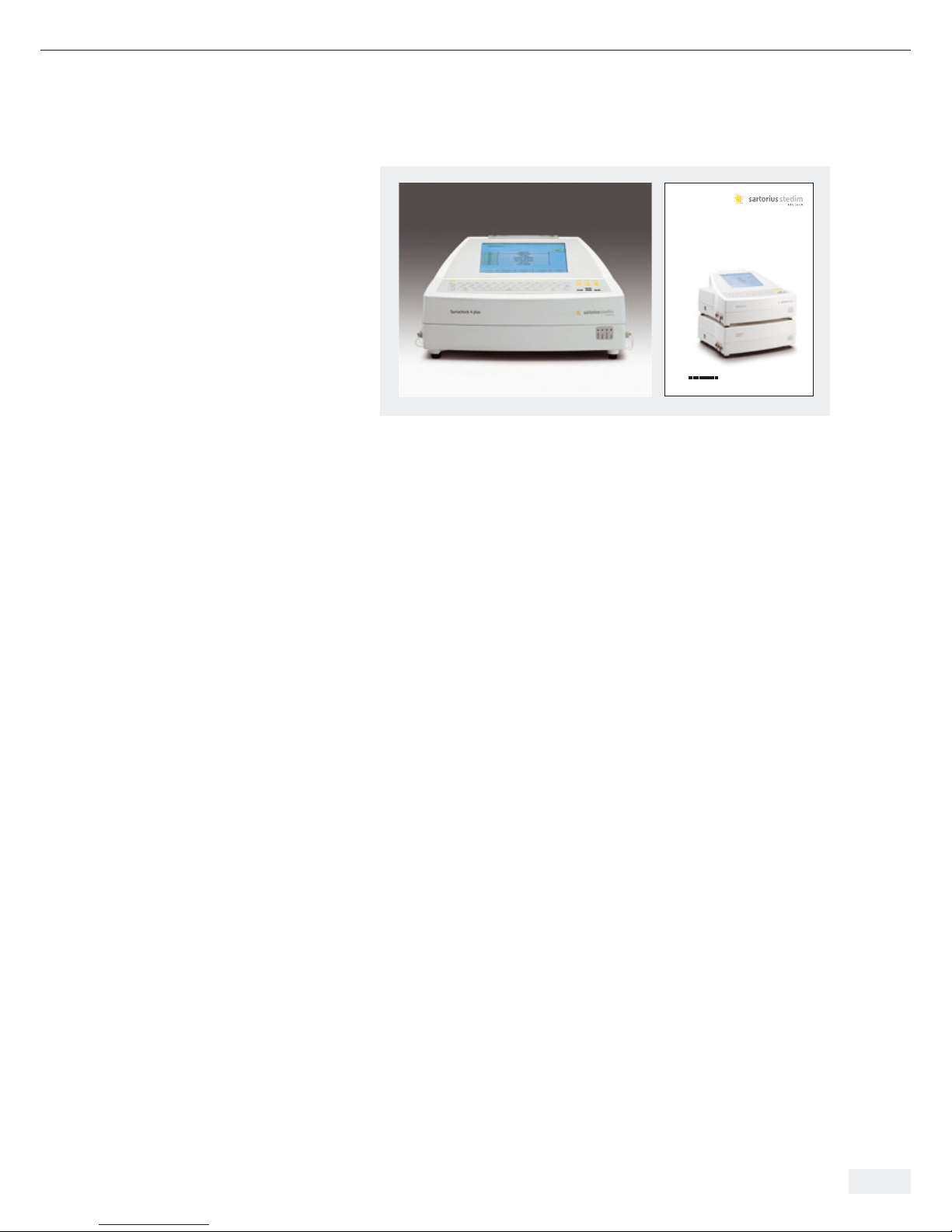
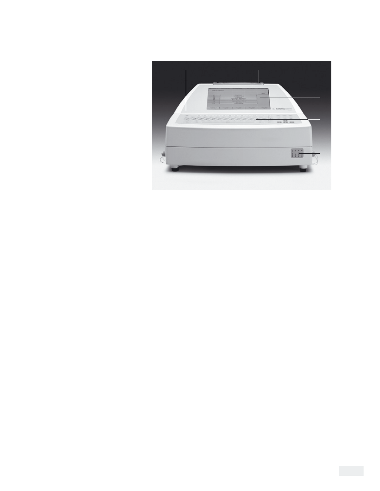
2.1 Overview: Sartocheck® 4 plus
Filter tester
Fig. 2-1 | Overview
Picture of Sartocheck® 4 plus Filter tester
1 Housing
2 Printer
3 Touch screen
4 Keypad
5 Indicator lights
Overview: Sartocheck® 4 plus Filter tester MultiUnit
Fig. 2-2 | Overview
2.2 Proper Use Sartocheck® 4 plus Filter tester is a filter integrity tester. It was exclusively developed,
constructed and built for the industrial and commercial purpose of conducting filter
tests in pharmaceutical and biotechnological production and laboratory operations.
The unit is not intended for use in or with explosive atmospheres!
The system is exclusively designed for the purpose defined above. Any other
application above or beyond this or any modifications to the unit without the
written permission of the manufacturer is not considered proper use.
12
3
4
5
6 Overview and Proper Use
Page 7
Sartorius Stedim Biotech GmbH cannot assume liability if Sartocheck® 4 plus test
units are subjected to improper use or improper operation. Sartorius Stedim Biotech
is not liable for any damages resulting therefrom. The operator bears the sole risk.
Proper use also includes compliance with operating, inspection and maintenance
conditions prescribed by the manufacturer. Non-compliance with the warnings in
the operating instructions and installation instructions, in particular, constitutes
improper use of the equipment. Only EMC-tested control leads and accessories may
be used. Units may only be returned in their original boxes or appropriate secure
packaging. No liability can be accepted for transport damage.
2.3 Technical Specifications
2.3.1 Dimensions and Weight Sartocheck
®
4 plus Filter tester
Length: 460 mm
Width: 390 mm
Height: 245 mm
Weight: 15 kg
Packing Weight: 2.7 kg
Sartocheck
®
4 plus Filter tester MultiUnit
Length: 460 mm
Width: 390 mm
Height: 150 mm
Weight: 13 kg
Packing Weight: 2.7 kg
2.3.2 Connection Data Sartocheck
®
4 plus Filter tester | Sartocheck® 4 plus Filter tester MultiUnit
Power requirements
Operating voltage: 100-240 V/±10%
Number of phases: 1 Ph/N
Neutral conductor: Loadable N (in the Appendix)
Grounding conductor: Separate SL (yellow-green) (in the Appendix)
Frequency: 47-63 Hz
Protection rating: IP 44
Installation: According to VDE regulations
Permissible voltage fluctuation: ± 10% from normal value
Maximum operating pressure: 10 bar g
Operating pressure: min. 4 bar g
Maximum power input: 74 Watt
Internal limit pressure: 10 bar g
2.3.3 Pneumatics Sartocheck
®
4 plus Filter tester | Sartocheck® 4 plus Filter tester MultiUnit
Required compressed air 4–9 bar g
Water, oil and particle free
2.3.4 Test Media Sartocheck
®
4 plus Filter tester | Sartocheck® 4 plus Filter tester MultiUnit
Test gas: Compressed air, dehydrated and deoiled
Wetting fluid: Water or as described with the process validation
documents for the filter cartridge to be tested
Overview and Proper Use 7
Page 8

8 Overview and Proper Use
2.3.5 Product-specific Data Manual input range upstream system volume 01) –150000 ml
Measuring Ranges
– Test pressure: 100–8000 mbar g
– Pressure drop: 1–2000 mbar
– Max. measurable volume: 150 L
– Diffusion: 0.1–3000 ml/min
– Water intrusion: 0.1–999 ml/10 min
– Water flow: 0.01–99.9 ml/min
– Bubble point: 100–8000 mbar
Measuring Accuracy
– Pressure ± 0.1% | ± 9.5 mbar full scale
– Pressure drop ± 1 mbar
– Net volume measurement ± 4%
– Diffusion ± 5%
– Water intrusion ± 5%
– Bubble point ± 50 mbar
Operating Conditions
– Room temperature +15°C to +35°C
– Rel. humidity 10-80%
Touch screen (Sartocheck
®
4 plus Filter tester only)
– Size 10.4“
– Color 256 colors
Interface Port for Data Output
– Serial port TU RS232| RS485
– Serial port MU RS232 (Sartocheck® 4 plus
Filter tester only)
– PLC port binary signals 12 pins
– Network Connection RJ45
Selectable languages:
English, German, French, Spanish, Italian
1)
When 0 is input, the upstream system volume is measured. Volume input and volume measurement are
not applicable for bag testing.
Page 9
Overview and Proper Use 9
2.3.6 Test Methods Test method Without ext. ref. tank With ext. ref. tank
Press. drop test All filter systems up to Not applicable
net volume of 150 L
Diffusion test
Cartridge systems up to Cartridge systems up
net volume of 14 L net volume of 150 L
Bubble point test Small systems and cartridge Small systems and cartridge
systems up to net volume systems up to net volume
of 14 L of 150 L
Multipoint diffusion Cartridge systems up to –
test net volume of 14 L
Diffusion and Cartridge systems up to Cartridge systems up to
bubble point test net volume of 14 L net volume of 150 L
(complete test)
Intrusion test, Cartridge systems up to –
water flow test net volume of 14 L
2.3.7 General Data Ambient conditions
Ambient temperature: +5 up to +35°C
Noise level: < 70 dB (A)
Humidity: 95% at 25°C
The unit should be set up under ambient conditions that produce no negative
effects during operation and processing, e.g. from contaminated airflows,
metallic dust or fluids from leaks, condensation, aerosols or widely changing
temperature conditions.
Page 10

3. Safety 3. Safety
Operating instructions are binding;
designated by a “book”.
Warnings
are designated by a “Hazard” triangle.
Electrical Hazards
are designated by the symbol to the left.
Notes
are designated by a “Hand”.
Grounding Conductor Connection
is designated by this symbol at the connection sites.
Mandatory Instructions
for handling electrical plug connections.
3.1.1 Manufacturer’s ID Label
Fig. 3-1 | Manufacturer’s ID Label Sartocheck® 4 plus Filter tester
Fig. 3-2 | Manufacturer’s ID Label Sartocheck
®
4 Filter tester MultiUnit
10 Safety
3.1 Notes | Warnings |
Descriptions
Page 11
The information given in these operating instructions applies to Sartocheck® 4 plus
Filter tester, Order no. 26288---FT and Sartocheck® 4 Filter tester MultiUnit,
Order no. 26288---FM.
The manufacturer’s label is affixed to the rear panel of the unit.
Important: if you have any questions
Always have the following information ready:
– Model
– Version
– Serial number
Having the right information readily available will ensure correct and quick
processing.
3.2 Installed Safety Equipment The installed safety equipment must be inspected at regular test intervals
(d = daily, w = weekly, m = monthly). The test methods used are: S = sight inspection,
F = functional testing.
The unit has the following safety equipment installed:
Line Disconnector
The unit is disconnected from the mains voltage by switching off the unit or when
the unit is unplugged from the wall outlet (mains supply).
Housing
All unit-specific components are shielded against external influences by a plastic
housing. It is strictly forbidden to disengage or dismantle the safety equipment.
The function of this safety equipment must be inspected and tested according to the
instructions given in the Chapter “Maintenance”.
The operator is responsible for instructing the operating personnel and
service and maintenance personnel about the meaning and the function
of the safety equipment.
These operating instructions are an integral part of the unit and must be available to
operating personnel and service and maintenance personnel at all times.
The safety precautions and warnings contained herein must be observed.
3.3 Safety Precautions The operator must
(to be carried out by – instruct their operating and servicing personnel in the use of the filter cartridge
the operator) housing’s safety devices and
– ensure that the safety precautions are complied with.
– prevent unauthorized persons (not operating and servicing personnel) from
accessing the filter cartridge housing danger zone.
These operating instructions must be kept in a safe place for future reference.
The frequency of inspections and checks must be observed.
The work described in these operating instructions is explained in such a way that it
can be understood by trained workers and qualified technicians.
Safety 11
Test
Interval Method
m S/F
Test
Interval Method
m S
Page 12
12 Safety
Definitions Adapted from EN 60204-1:
Trained Worker
A person familiarized with and, if applicable, trained in their particular duties by
a qualified technician and instructed about the potential dangers in the event of
improper conduct and on the necessary safety devices and safety precautions.
Qualified Technician
A person who, by virtue of their technical training, know-how, experience and
knowledge of relevant standards, is able to assess the work assigned to them
and identify potential dangers.
3.4 Operator’s Obligations
In the European Economic Area (EEA), the laws to nationally implement Council
Directive (89/391/EEC), as well as the corresponding individual Directives and specifically including Council Directive (89/655/EEC) concerning the minimum safety and
health requirements for the use of work equipment by workers during labor, must be
observed and complied with in their respectively valid versions.
In Germany, the Operational Safety Regulation dated October 2002 must be
observed (regulation transposing the above-mentioned Directives into national law).
The operator must obtain a local operating permit and follow the regulations and
restrictions set forth therein.
Additionally, the operator must comply with the local rules and
regulations for:
– The safety of the personnel (accident prevention regulations)
– The safety of the work equipment (protective gear and equipment and
maintenance)
– Product disposal (Waste Management Act)
– Material disposal (Waste Management Act)
– Cleaning (cleaning agents and disposal) and the environmental rules
and regulations.
3.5 Safety Tests and Inspections 1. Measurement of airborne noise
Carried Out by the 2. Testing and inspection according to DIN EN 61010-1
Manufacturer at the Facilities
Page 13
General Warnings 13
4. General Warnings 4. General Warnings
4.1 Hazards The safety systems and safety notes described in these operating instructions should
be complied with accordingly.
Keep the work area of the Bag tester free of objects during operation so that
unimpeded access is possible at all times.
Before any installation, servicing or repair work is carried out, make sure you
are aware of the electrical hazards!
Unplug the equipment from the wall outlet (mains supply) before opening it!
Observe the required operating conditions, especially with regard to the temperature
of the medium. It is transmitted to the components. Touching components or contact
with the medium can result in burns or scalding.
In order for the Sartocheck® 4 plus Filter tester to be EMC compliant, the original
Ethernet cable must be used.
4.2 Operating Personnel and Operating personnel and service and maintenance personnel are persons who are
Service and Maintenance responsible for the transport, installation, operation, equipping, maintenance and
Personnel cleaning as well as troubleshooting on the unit.
1. The unit may only be operated by trained and authorized persons in accordance
with operating instructions that have been issued by the operator.
2. The responsibilities for operation of the unit must be clearly set down and
observed so that no ambiguities arise with respect to safety.
3. The safety precautions and warnings given in the operating instructions must be
complied with when carrying out any work (operation, maintenance, repairs etc.).
4. The operator shall never work in any way that could impair the safety of the
unit or him | herself or others.
5. It is the responsibility of the operator to ensure that only authorized persons
work on the unit.
6. It is the responsibility of the operator to report immediately any changes
occurring on or to the unit to the operating company.
7. It is the responsibility of the operator to ensure that the unit is only operated
in perfect working condition.
Page 14
4.3 Installation of Please note that replacement parts and Replacement Parts accessories that not have
been supplied by Sartorius Stedim Biotech GmbH have not been tested and approved
by Sartorius Stedim Biotech GmbH. The installation of and|or the use of such
products can therefore have a negative effect on the design properties of the unit as
constructed.
Sartorius Stedim Biotech GmbH is not liable for any damages resulting from the use
of non-original parts or non-original accessory parts.
Standard parts can be purchased from specialized dealers.
4.4 Shutdown Procedure
The following shutdown procedure must be followed before any cleaning,
servicing or repair work is carried out.
1. Line disconnect
Turn off the main switch by pulling out the AC adapter of the mains supply.
2. Compressed air supply
Turn off the compressed air supply and vent system.
Personnel may suffer physical injuries or fatalities if this procedure is not followed!
14 General Warnings
Page 15
5. Installation 5. Installation
5.1 Equipment Supplied
Fig. 5-1 | Sartocheck® 4 plus Filter tester
The equipment supplied with the Sartocheck® 4 plus Filter tester includes:
1. Sartocheck® 4 plus Filter tester, Order no. 26288---FT
2. Operating instructions and technical documents
3. Accessories (not shown in the picture)
– Tubing “Inlet” with compressed air filter (I.D. = 6 mm) Order no.: 18104
– Tubing “Outlet” (I.D. = 4 mm) Order no.: 18103
– Spare ink ribbon cartridge Order no.: 6982141
– Spare roll of printer paper Order no.: 6982142
– Country-specific power cord
The equipment supplied with the Sartocheck® 4 Filter tester MultiUnit includes:
1. Sartocheck® 4 Filter tester MultiUnit, Order no. 26288---FM
2. Operating instructions and technical documents
3. Accessories (not shown in the picture)
– Tubing “Inlet” with compressed air filter (I.D. = 6 mm) Order no.: 18104
– Tubing “Outlet” (I.D. = 4 mm) Order no.: 18103
– Country-specific power cord
– Connecting cable Sartocheck
®
4 plus Filter tester MultiUnit and
Sartocheck® 4 plus Bag tester MultiUnit, Order no.: 1ZE---0010
5.2 Receipt of Delivery Incoming inspection:
– Check the shipment for damage!
– Check the shipment against the delivery note to ensure that it is complete!
Complaints
If the shipment was damaged during transit:
– Immediately contact the carrier!
– Keep the packaging material (in case the carrier wants to inspect it or
the shipment has to be returned to us)
If the shipment is not complete:
– Immediately contact Sartorius Stedim Biotech GmbH or the Customer Service
Department in your country!
If the delivery has other defects:
– Immediately contact Sartorius Stedim Biotech GmbH or the Customer Service
Department in your country!
Operating Instructions | Betriebsanleitung
Sartocheck® 4 plus Filter tester | Filter tester MultiUnit
Filter Integrity Tester | Filterintegritäts-Testgerät
85032-536-78
1 2
Installation 15
Page 16
Packaging for Return Shipment
Use the original packaging and original packaging material as far as possible.
If the original packaging and original packaging material are
no longer available:
– Commission a packaging company with specialized technicians.
– Pack the unit in a shipping container in such a way that mechanical
damage is prevented.
If you have any questions about packaging and transport securing devices,
please contact Sartorius Stedim Biotech GmbH.
Check the equipment supplied against the delivery note. Please report incomplete
deliveries immediately to the shipping carrier or the supplier.
Interim Storage
The external packaging of the unit and its spare and replacement parts is designed
for a storage period of three months from delivery.
Units kept in interim storage must be stored in a closed, dry room at temperatures
from +5°C to max. +50°C.
5.3 Installation Instructions
5.3.1 Ambient Conditions Select a place of installation that meets the following conditions:
and Conditions at the Place t No relatively high temperature or exposure to heat or sun
of Installation t No strong drafts
t No aggressive chemical environments
t No strong vibrations
t No dust
t No major humidity effects
5.3.2 Transporting and The unit and its accessories are packaged according to the national custom and
Unpacking the Equipment protected against impacts. To avoid damaging the equipment, please comply with
the following notes and instructions:
t Please observe the Technical Specifications in Chapter 3!
t Please observe the weight. For transport to the unpacking site, use a floor
truck if appropriate.
t
To prevent the unit from slipping, it should always be carried or lifted by two people.
t To open the packaging, remove the unit and place it on a workbench
or table intended for that purpose.
t The workbench or table must be level and able to bear the appropriate load.
Allow sufficient space around the workbench or table for the operator to work.
t Unpack the accessories and technical documents and put them in a safe place.
t Moisture in the air can condense on the surfaces of a cold unit whenever it is
brought into a substantially warmer place. If you transfer the unit to a warmer
area, make sure to condition it for about 2 hours at room temperature, leaving it
plugged into AC power. The positive temperature differential between the inside
of the unit and the ambient environment essentially protects the unit against
humidity and moisture.
Open the packaging carefully. It is a good idea to save the packaging material
(in case the carrier wants to inspect it or the shipment has to be returned).
Dispose of packaging materials in compliance with prevailing environmental
safety regulations.
16 Installation
Page 17
5.4 Connections Before starting up the unit; make sure that the unit is stable and secure.
Check all pneumatic and electrical connections on the unit.
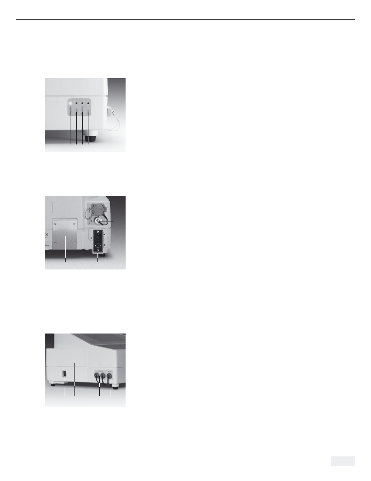
5.4.1 Front Panel and Back Panel The following displays are located on the front panel:
1 Standby
Is lit up when Sartocheck
®
4 plus Filter tester is ready for operations, but not
currently running any test program. (Blinking LED)
2 Ready
Lights up when the result of the filter test is ready. (LED lit)
3 Running
Is lit up when a test is currently running. (LED lit)
4 Error
Lights up when the test unit has identified an error and cancelled the test.
(LED lit)
The following connection ports are located on the back panel:
1 Housing ventilator
The unit is equipped with a ventilator that ensures that Sartocheck® 4 plus
Filter tester is kept at a constant temperature.
2 Serial port MU (Management Unit)
This port is used for connecting accessories (e.g. barcode scanner).
3 AC adapter
Power plug for connecting the power cord to mains supply.
4 Fuses
Fine-wire fuses between unit and mains supply.
5 Network Connection
RJ45
5.4.2 Left and Right Panels
Sartocheck® 4 plus Filter tester Located on the left panel:
1 Main power switch
Switch on the power with the main power switch.
2 SD Card Reader
The SD card reader is designed for standard SD cards for inputting and
storing data.
3 Serial port TU (test unit)
Port for connecting additional test units (Multiunits).
4 PLC Port
Port for connecting PLC controller signal input and output.
1 2 3 4
Fig. 5-2 | Front Panel
14
3
2
5
Fig. 5-3 | Back Panel
1 2 3 4
Fig. 5-4 | Left panel
Installation 17
Page 18
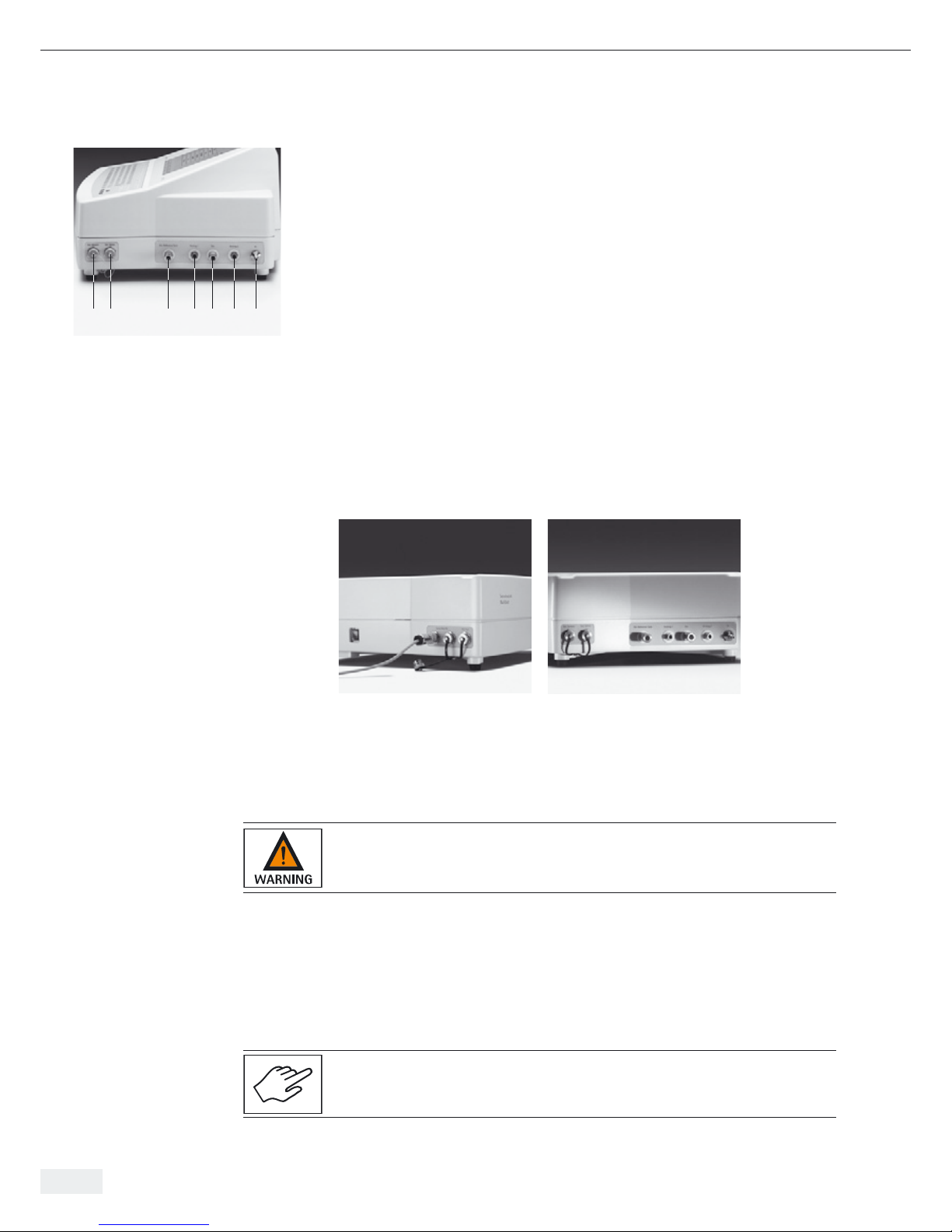
Located on the right panel:
1 Ext. sensors
Port for connecting an external pressure sensor.
2 Ext. valves
Port for connecting external valves.
3 Ext. reference tank
Quick connector for external reference tank.
4 Venting 1
Quick connector for Venting 1.
5 OUT
Quick connector for test tubing.
6 Venting 2
Quick connector for Venting 2.
7 IN
Quick connector for compressed air supply.
5.4.3 Left and Right Panels
Sartocheck
®
4 Filter tester MultiUnit
5.5 Pneumatic Connections Sartocheck® 4 plus can be operated with an internal pressure sensor and with
different ports for connecting tubing. The ports for connecting tubing, for both
the Sartocheck® 4 plus and Sartocheck® 4 MultiUnit, are illustrated in Fig. 5-8,
Fig. 5-9 and Fig. 5-10.
Do not connect Sartocheck® 4 plus Bag tester to pressurized or high temperature systems! Wait until the whole system is at room pressure and temperature!
Inlet Pressure During Operation with Internal Pressure Sensor
The minimum operating pressure required depends on the test method selected,
but should be at least:
> 4000 mbar and > 500 mbar above the test pressure or above the max. B.P. entered.
Sartocheck® 4 plus automatically detects the operating pressure during the function
test before starting each test and during the whole test sequence.
Check to make sure that all inlet and outlet pressure tubing is connected properly,
that all electrical connections have been correctly installed, and that the paper roll
as well as the ribbon cartridge have been inserted.
1 2 3 4 5 6 7
Fig. 5-5 | Right panel
Fig. 5-6 | Left panel Fig. 5-7 | Right panel
18 Installation
Page 19

Installation 19
Fig. 5-8 | Connection with internal pressure sensor
Fig. 5-9 | Connection with internal pressure sensor and external vent
Fig. 5-10 | Connection with internal pressure sensor and external volume reference tank
Sartocheck 4 plus
Sartocheck 4 plus
Sartocheck 4 plus
Page 20

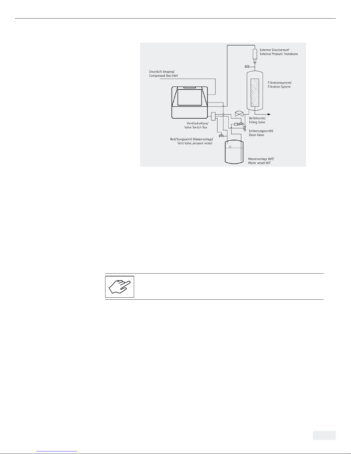
5.6 Connections with Sartocheck® 4 plus can be operated with an external pressure sensor and with
External Pressure Sensor different ports for connecting tubing. The ports for connecting tubing, for both the
Sartocheck
®
4 plus and Sartocheck® 4 MultiUnit, are illustrated in Fig. 5-11, Fig. 5-12
and Fig. 5-13.
Check to make sure that all inlet and outlet pressure tubing is connected properly,
that all electrical connections have been correctly installed, and that the paper roll
as well as the ribbon cartridge have been inserted.
Fig. 5-11 | Connection with external pressure sensor and manual valves
Fig. 5-12 | Connection with external pressure sensor and external valves
Sartocheck 4 plus
Sartocheck 4 plus
20 Installation
Page 21
Installation 21
Fig. 5-13 | Connection with external pressure sensor for WIT
5.6.1 Inserting Paper Roll To insert or change the paper roll, lift the cover off the paper feed. Pull the feed
Ribbon Cartridge mechanism out of the assembly and push the cover to the left and lift it out
of its attachments. Now lift the paper feed mechanism out of the Sartocheck® 4 plus
housing.
Insert a new paper roll into the paper slot and slide the paper feed mechanism back
into the housing. Thread the end of the paper through the slot of the paper feed.
Make a final check to ensure that the feed mechanism is locked in place.
Close the printer cover and secure the splashguard. Check to make sure that the
splashguard is locked in place.
To change the ribbon cartridge (when the feed mechanism is pulled outwards)
lift the previously installed cartridge out of the paper feed and insert a new one.
Apply slight pressure to lock the cartridge in.
Sartocheck 4 plus
Page 22

22 Installation
5.6.2 Sartocheck® 4 plus Sartocheck® 4 Bag tester MultiUnits are connected to the Sartocheck® 4 plus Filter
Filter tester MultiUnits tester MultiUnit or to the Sartocheck® 4 plus Bag tester via the serial port TU
connection ports. Different ways of connecting are shown below in Fig. 5-14 to 5-17.
The location of the Sartocheck
®
4 Bag tester MultiUnits, relative to the Sartocheck®
4 plus Filter tester or to the Sartocheck® 4 plus Filter tester MultiUnit, will determine
which method is best suited for the application.
Fig. 5-14 | Serial connection to a Bag tester
Fig. 5-15 | Serial connection to a Filter tester
Page 23
Function 23
6. Function 6. Function
Fig. 6-1 | Overview
Picture of Sartocheck® 4 plus Filter tester
1 Housing
2 Printer
3 Touch screen
4 Keypad
5 Indicator lights
6.1 General Functional Description Sartocheck® 4 plus Filter tester is a qualifiable filter integrity testing unit, consisting
of a data management unit, a test unit and up to four additional Filter tester
MultiUnits or Bag tester MultiUnits.
The test unit is a mechanically, pneumatically and electrically closed functional unit.
A test unit cannot be operated directly by the user, but is 100% controlled by the
data management unit via an internal RS 485 interface. With the help of its electrical
and pneumatic peripheral devices, the data management unit performs the actual
filter tests along with a series of other additional functions.
Bag Test
The main purpose of Sartocheck® 4 plus Bag tester is to test single use bags and
single use bioreactors according to the pressure drop method.
Filter Integrity Test
The main purpose of Sartocheck® 4 plus Filter tester is to test the integrity
of membrane filters according to various methods.
6.2 Test Programs In the test program, the procedural steps and the parameters are set down for either
the bag test or for the filter integrity test.
A programmed test program can be loaded into the test unit and the test will be run
independently.
– Load a test program
– Run a test program
The test unit runs through the previously loaded test program, in other words,
it carries out the test and saves the result in non-volatile memory. The data management unit monitors the progress of the bag test or the filter integrity test, i.e. it reads
in the current data in order to present them to the user.
12
3
4
5
Page 24

24 Function
6.3 Managing the Test Results Sartocheck® 4 plus Filter tester processes the measured raw data (the test results),
which means that the unit values are converted and numbers transformed into text.
6.4 Function Test With the function test, the user is able to interactively test the functionality
of pneumatic components. The proportional valves are not explicitly, but rather
implicitly tested in this context.
6.5 Cleaning Sartocheck
®
4 plus Filter tester starts the procedure for cleaning and flushing the
internal lines and the volume reference tank.
6.6 User Interrupt The user can interrupt any test on Sartocheck
®
4 plus Filter tester by pressing the
[STOP] button. Pressing the [arrow upwards] and [STOP] buttons simultaneously
will interrupt tests on all Sartocheck® 4 plus Filter tester MultiUnits or
Sartocheck® 4 Bag tester MultiUnits connected to the Sartocheck® 4 plus Filter tester,
as well as any test running on the Sartocheck
®
4 plus Filter tester unit.
6.7 Self-Test for Broken While controlling the valves and sensors, the Sartocheck® 4 plus Filter tester
Conductors and Short-Circuiting hardware can check whether there are any broken conductors or short-circuits.
6.8 Calibration The calibration function is designed to calibrate the internal pressure sensor with
the help of more accurate reference measuring equipment, and if necessary, adjust it.
The sensor has a monitored calibration date.
An adjustment routine automatically follows the test. The test can also be activated
separately. Sartocheck® 4 plus Filter tester saves the raw data for the calibration
record in permanent memory.
The operator can use the following sensor type for determining the reference
pressure:
t Relative pressure sensor:
The measured reference pressures relate to the ambient pressure. The ambient
pressure must be known or measured with additional reference measuring
equipment.
6.9 Internal Pressure Sensor Sartocheck® 4 plus Filter tester sets 8 pressure values and compares them with
the internal pressure sensor and the pressure values measured on the reference
measuring instrument (connected to the “OUT” connector) to calculate scale
and linearization.
6.10 Pressure Gauge Function When in the pressure gauge function, Sartocheck
®
4 plus Filter tester acts like
a digital pressure measuring device.
6.11 Cleaning | Drying Through the pneumatic connectors, Sartocheck
®
4 plus Filter tester is able to
flush almost all internal volumes. It is the responsibility of the user to use original
Sartocheck® equipment only (Cleaning Kit type 26288---CK”).
6.12 Safety Functions t As one of its technical options, Sartocheck® 4 plus Filter tester runs the test step
Initialization | Security Status in the event of a power failure. Basically, what this
step does is close the compressed air supply and the block valve to the test set-up.
t Sartocheck® 4 plus Filter tester is not responsible for ensuring whether the
pressure supplied to the system being tested is too high. This means that the
user must make sure that the programmed pressure cannot damage the system
being tested.
Page 25

Function 25
6.13 Software Update The operating software on Sartocheck® 4 plus Filter tester is updated with a
corresponding program run with an external PC|laptop. The Management Unit
may be updated with an SD card. Since the configuration data are localized in
a battery-backed RAM, they remain unchanged during any software update.
6.14 Serial Number Every unit bears its own unique serial number. The serial number may not be changed
during a software update.
t The serial number is entered for the first time during production of the unit.
t If the PCB has to be replaced during repairs that may arise later,
the unit must be assigned the exact same serial number that is imprinted
on the manufacturer’s label.
Page 26
26 Function
7. Operation 7. Operation
7.1 Switching On the Unit
Fig. 7-1 | Overview
Picture of Sartocheck
®
4 plus Filter tester
1 Housing
2 Printer
3 Touch screen
4 Keypad
5 Indicator lights
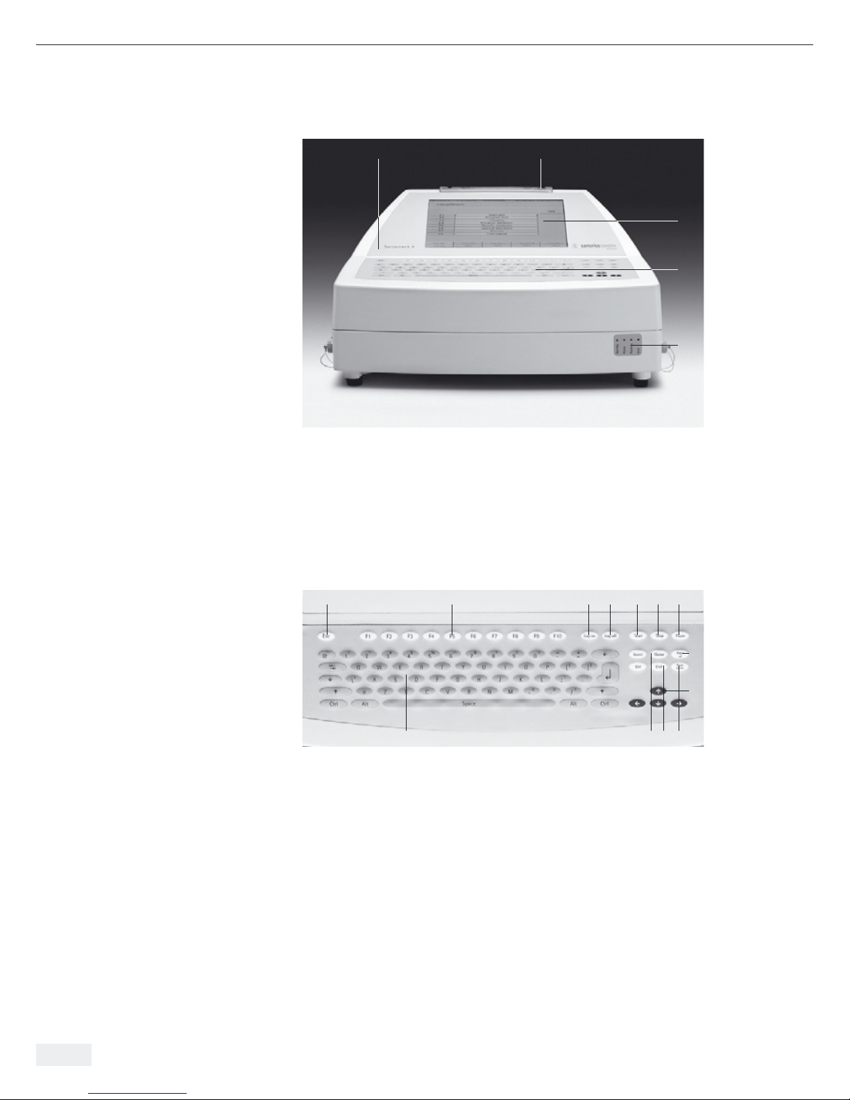
7.1.1 Operating Elements
Fig. 7-2 | Display and control panel
The display and control panel features the following operating elements:
1 Esc
Press this key to cancel the current procedure.
2 F1-F 10
Function keys F1-F10 correspond to the function types displayed on touch screen.
3 Log on
Press this key to switch on the log-on screen.
4 Log off
Press this key to log the current user off.
12
3
4
5
8 109 12
11
13
7
654321
Page 27

Function 27
5 Start
Press this key to start a test.
6 Stop
Press this key to stop a running test.
7 Paper
This key advances the paper in the internal printer.
8 PC keypad
Is used for inputting and starting processes.
9 Home
When this key is pressed, programming is cancelled without saving. The former
test is reinstated and the user is automatically taken back to the Main Menu.
10 End
Press this key to jump to the end of the input line when entering parameters
and data.
11 Page up
Press this key to scroll a page back in the service menu guidance.
12 Page down (toggle key)
Press this key to scroll to the next service menu window.
13 All Test Stop
Pressing the [Ç] and [STOP] buttons simultaneously will stop all running tests
on all MultiUnits, as well as any running test on the Sartocheck
®
4 plus Filter
tester unit.
Both the keypad and the touch screen can be used to operate Switching Sartocheck®
4 plus Filter tester. These two options can also be combined.
Individual menu items can be selected Sartocheck® 4 plus Filter tester with function
keys, on the keypad or by pressing the touch screen. Selection from lists is done by
entering the line number or by direct selection on the touch screen.
All dialog boxes are set up so that the operator can tell by the color which part
of the touch screen can be operated, which are the input boxes and which areas are
for information only. Function keys and other keys that can be pressed on the
screen and on the keypad are highlighted in yellow.
Input boxes are white. Non-changeable information boxes or function keys
that have already been activated are highlighted in gray. Selected dialog boxes are
colored blue. Warnings and error messages appear in red.
Page 28
28 Operation
7.2 Switching the Unit If you want to switch the unit on, proceed as follows:
ON and OFF
Before you switch on the power supply and the compressed air, compare the
connection data for the unit (see the Chapter 01 Technical Specifications) with
the data for the mains current and the compressed air supply.
Connect Sartocheck® 4 plus Filter tester to the mains supply by plugging the power
cord into the wall outlet, install all tubing connections. The unit is now ready for
operation.
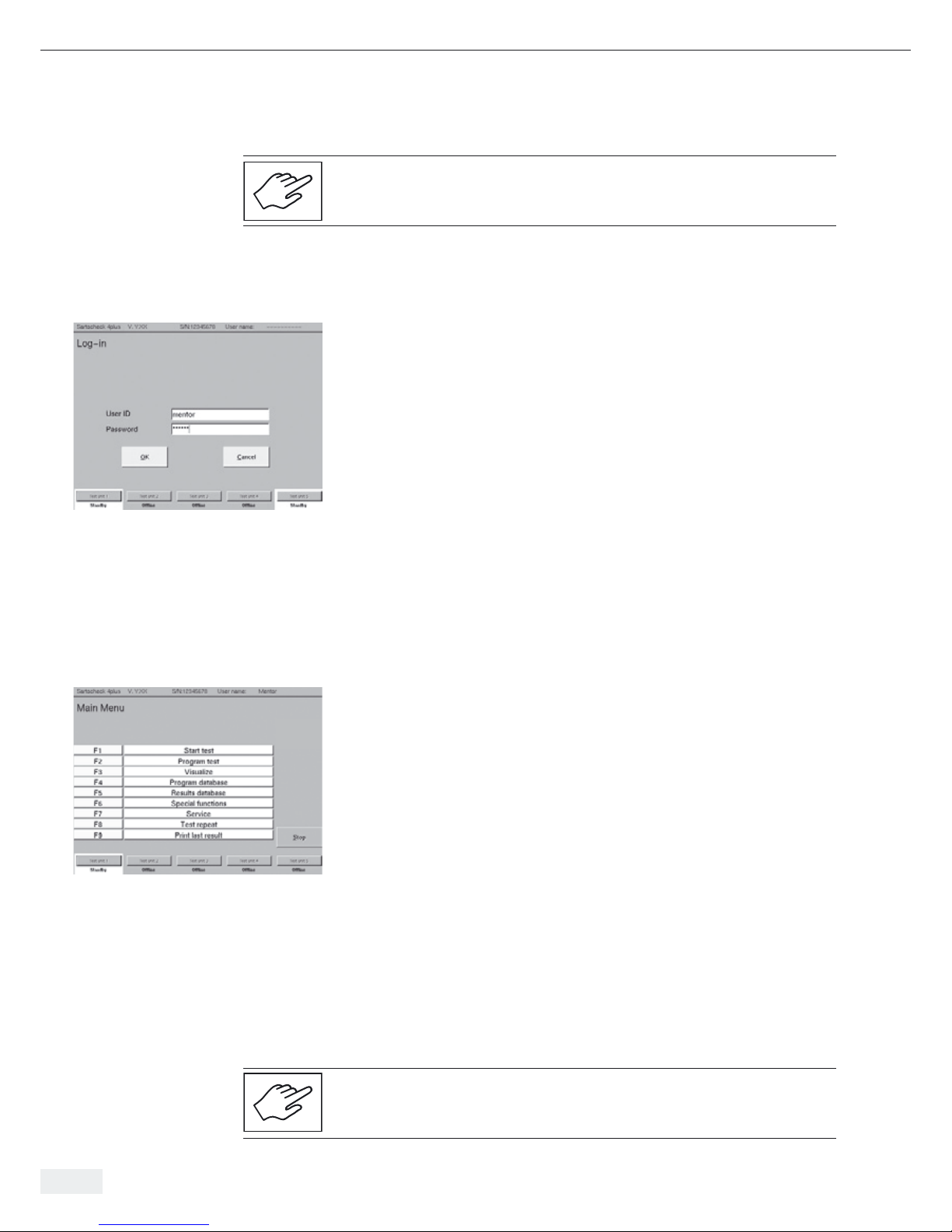
Login menu
User ID: Enter operator’s name
Password: Enter operator’s password
OK: Confirm correct entry
Cancel: Delete entry
Important Note: When Sartocheck® 4 plus Filter tester is delivered it is factory
set for the following user:
Name: mentor
Password: mentor
Operators must log-in before activating the Main Menu.
The operator logs in by pressing the “Login” key on the keypad. After pressing the
“Login” key, the user will be asked for their name and password. When both are
entered correctly, the keypad and touch screen are released for use. When the operator stops working with Sartocheck
®
4 plus Filter tester, they must always log out by
pressing the “Logout” key. Sartocheck® 4 plus Filter tester is then blocked for further
operation until another operator logs in.
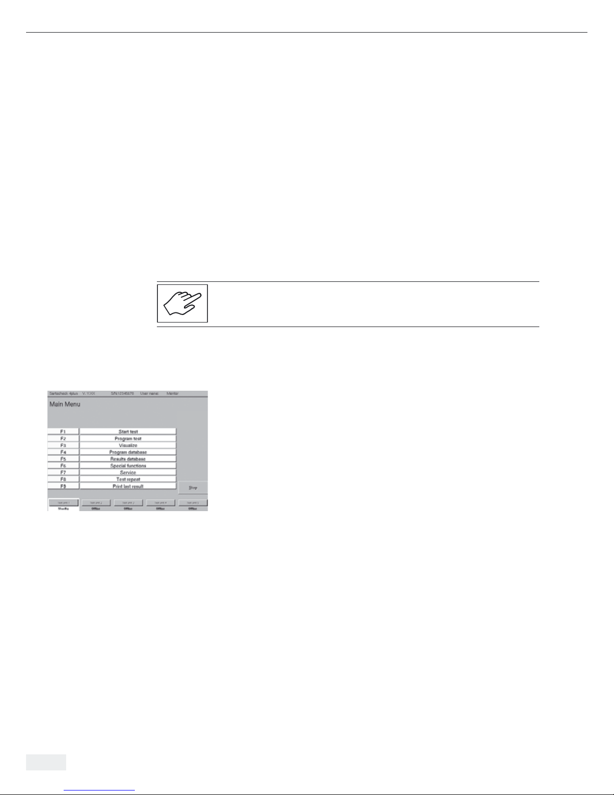
Information line with model, version, system number and user name.
Menu display: Main Menu
F1-F8: Select the function menus with the function keys
Selects the function menus
Functional unit selected and operational status.
The Main Menu appears.
t Before starting a test, allow the unit to warm up for about 20–30 min.
For shut-down times < 30 min and constant ambient temperatures, the warm-up
phase can be shortened accordingly. For more information about the tests, see
Chapter 7.3 ff.
t Program the data for the test routine.
t The Sartocheck® 4 plus Filter tester ready for operation (by the logged-in user).
t Start the test.
Only service technicians or trained personal may install connections and start up
the unit!
Fig. 7-3 | Login menu
Fig. 7-4 | Main Menu
Page 29

Operation 29
7.2.1 Running a Test Run the test according to the test procedure that you selected and programmed.
7.2.2 Switching Off the Unit When switching off the unit, proceed as follows:
t Run the test to the end.
t Close the compressed air supply at the compressed air supply port.
t Run the log-off function.
t Turn off the main power switch.
7.2.3 Switching Off the Unit in In the event of a power failure, all valves will be switched to a secure state.
the Event of a Power Failure This guarantees that the system being tested is vented. The ongoing test is cancelled.
No test result will be available.
Loss of Compressed Air
In the event that the compressed air supply stops, the test is automatically
cancelled and an error message appears. “Target pressure not reached”. The system
is vented automatically. When the supply of compressed air resumes, the unit must
be restarted and the test repeated.
7.3 Tests
7.3.1 Test Parameters To obtain reliable and reproducible test results, observe the following:
t Run the test at room temperature (approx. 15–30°C), whenever possible.
t During a test run, always avoid any temperature changes.
t The upstream side of the system must be absolutely leak-free
t Do not connect the tester to pressurized systems.
t For filter testing: If you wish to use other types of compressed gas and| or wet-
ting fluids not specified by Sartorius Stedim Biotech, consult your local Sartorius
Stedim Biotech office or Sartorius Stedim Biotech GmbH in Germany.)
t For the Water Intrusion Test, the surface tension of the water must be
> 70 dyn/cm.
t Always enter correct test parameters. Incorrect test parameters will lead to
incorrect test results or erroneous evaluations.
Calibration
The Sartocheck 4 plus Filter tester should be re-calibrated at least once a year,
twice being preferable.
Page 30
30 Operation
7.3.2 Test Methods With the Sartocheck® 4 plus Filter tester, you can directly select a particular test
method. This greatly simplifies programming the data for a test, since only the
parameters that are relevant for the selected test are displayed.
You can select any of the following test methods:
Test methods
1 Diffusion test
2 Bubble point test (Standard and Customer specific)
3 Diffusion and bubble point test
4 Water intrusion test
5 Pressure drop test
6 Multipoint diffusion test (Standard and Customer specific)
7 Volume measurement
8 Plate holder test
9 Installed bag test
System Venting
At the end of each test, after a power failure or after switching off the unit during
a test, the system is automatically vented.
7.3.3 Programming Tests The Sartocheck® 4 plus Filter tester cannot perform bag tests.
(F2 – Main Menu) Nevertheless it is possible to program bag tests due to the fact that additional Bag
tester MultiUnits may be connected to the Filer tester. The test parameters for the
individual tests are entered and selected on Sartocheck
®
4 plus Filter tester by using
the keypad or the touch screen. The Main Menu is the starting point for programming. The following example uses a diffusion test to illustrate how to program
data for tests and run test sequences (F2 – Main Menu). The programming and test
sequences are identical for the other test types.
Before we start programming, we would like to explain a few important keys
and|or touch commands.
The Sartocheck® displays are set up with yellow buttons located on the right side
of the screen. These buttons always have the same functions:
Main Menu: The program jumps back to the Main Menu (see Fig. 7-5)
Page Up: the program scrolls to the previous page of the screen
Page Down: the program scrolls to the next page of the screen
List Up: Whenever a list is displayed on the screen, use LIST UP
to scroll up the list
List Down: Whenever a list is displayed on the screen, use LIST DOWN
to scroll down the list
Enter: Confirms the selected function, action or entry.
Following confirmation, the yellow key turns gray
Fig. 7-5 | Main Menu
Page 31

Operation 31
Programming Tests
Select the programs in the menu “Programming tests: Program selection”. You can
select existing programs by entering the line numbers or by selecting them directly
on the touch screen. The selected line is highlighted in blue. Scroll back and forth
in the program selection list with List DOWN|UP. Confirm the selected program line
by pressing Enter. The Enter key turns gray. If you would like to correct the program
memory location, select a new line number or highlight the new line directly on
the touch screen.
Re-confirm by pressing Enter. Press PAGE DOWN to scroll to the next page.
The diffusion test is used as an example.
If the optional Barcode Scanner is used for programming, please compare chapter
7.18 on page 49).
Optional Parameters for Detection of Disconnected Filters
In case of a disconnected filter (housing), an integrity test can be successfully
performed because the test-evaluating parameters (e.g. BP
min
, Diff
max
) are fulfilled.
To avoid such situations, it is possible to define four additional parameters.
A non-standard test (compare fig. 7-8) must be chosen to get access to these
parameters. As soon as at least one of these listed parameters are not fulfilled, a
warning message is displayed | printed. The following parameters can be defined:
Min. limits: Parameters can be activated | deactivated
The parameters can be activated / deactivated.
If deactivated the here below described limits will have no impact
on the test sequence.
Min. DIF/WIT/WFT: A minimal diffusion rate can be defined.
This parameter is valid for diffusion test, WIT and WFT.
If the measured value falls below this limit a warning message
will be printed at the end of the test together with the test
evaluation. It is then responsibility of the of the quality assurance
to decide if the test is conforming or not.
The test evaluation of the Sartocheck 4 plus remains “passed”.
Min. Flow BPT: A minimum flow rate can be defined for the Bubble Point Test.
This value represents the minimum flow that must be
measured at BP
max
.
If the measured value falls below this limit a warning message
will be printed at the end of the test together with the test
evaluation. It is then responsibility of the quality assurance to
decide if the test is conforming or not.
The test evaluation of the Sartocheck 4 plus remains “passed”.
Min. Volume: A minimal net volume can be defined. A net volume measure-
ment below this value will abort the test. An error message will
be printed.
Max. Volume: A maximal net volume can be defined. A net volume measure-
ment above this value will abort the test. An error message will
be printed.
Fig. 7-6 | Programming tests: Program selection
Fig. 7-6b | Optional parameters
Page 32

32 Operation
7.4 Diffusion Test When pressure is applied to the upstream side of a wet filter, a diffuse gas stream
starts to flow through the filter membrane after a short time. Diffusion is dependent
on the effective filter surface area. The diffusion test is not suitable for testing disk
filter systems. However, the diffusion test is a very well suited test method for the
integrity testing of medium-sized and larger filter cartridge systems starting from
approx. 150 cm
2
. The diffusion value refers to a test pressure, which means there is
a direct correlation to the actual retention behavior of the filter (for a more detailed
description, see Chapter 12, Appendix).
In the menu “Programming tests: Program selection”, the test type is selected.
– Select test type (standard test or user-defined test)
In the menu “Test parameters: External connections,” decisions about external
connections and the configuration are entered. The function keys are used here to
enter the appropriate settings. The following external connections and parameters
must be configured for all tests:
– Standard test (Yes|No)
– External pressure sensor (Yes|No)
– External valves (Yes | No)
The parameters for the standard test are defined in the configured Service Menu.
Unlike the defaults (standard values), the values can be individually adjusted.
For the diffusion test, you have the following options:
Pressure unit: mbar|psi|hPa
Automatic test mode: No| Yes
Enter parameters for the diffusion test
Test pressure: from 100 – 8000 mbar
Stabilization time: in min.
Test time: in min.
Max. diff.: in ml/min
Net volume: in ml
In the menu “Test parameters: Diffusion test,“ the parameters for the diffusion test
are entered with or without net volume measurement.
For tests with volume measurements:
– Test pressure
– Stabilization time
– Test time
– Max. diffusion
When conducting tests without volume measurement, net volume should
be entered separately.
The test parameter data can be found in the validation documents of the respective
filter cartridge.
Locks
The locks are activated for the test parameters (default). After entering with the
Shift + F keys, the programmer can lock the data to prevent any changes.
The dialog boxes are then highlighted in gray. The user can no longer change
the entered data.
Fig. 7-7 | Programming tests: Program selection
Fig. 7-8 | Test parameters: External connections
Fig. 7-9 | Test parameters: Diffusion test
Page 33

Operation 33
Enter record data 1 (up to 32 characters per field)
Company: Company name
Building: Building name; house number
Department: Identification of the department
Manufact. site: Production sector
Product: Product name
Product lot: Batch number
Filter: Filter size
Filter lot: Number of the filter batch
Locks
After entering with the Shift + F keys, the programmer can lock the data
to prevent any changes. The dialog boxes are then highlighted in gray.
The user can no longer change the entered data. The relevant record data are
entered in the menu “Test program: Record data 1.”
Entry of record data 2
Filter line: Name of filter line
Housing: Type of housing
Wetting medium: Type of wetting medium
Test gas: Type of test gas
Water quality: Data on water quality
Comment: Name of operational process
Comment 2: Enter test-relevant remarks
Comment 3: Enter test-relevant remarks
Start the Test Program
Save:
After confirmation, the data are saved
The menu “Test program: Start” lists the options for that test start.
Once the programming is finished, the test can be started.
Choose the test unit on which to perform the integrity test.
Only test units that are currently available will be selectable.
Fig. 7-10 | Test program: Record data 1
Fig. 7-11 | Test program: Record data 2
Fig. 7-12 | Test program: Start
Fig. 7-13 | Test unit selection
Page 34

34 Operation
The test sequence is structured as follows:
Pressurization
Sartocheck
®
4 plus Filter tester adjusts the pressure to the pre-programmed test
pressure.
After a short waiting period during which the system is tested for major leakage,
the program goes into the stabilization phase.
Stabilization Phase
During the stabilization phase, the test pressure is adjusted to the exact desired
value. Fluctuations in test pressure occur as a result of cartridge compaction and
temperature variations created by the different filter housing temperatures and
the downstream air flowing in from the compressed air supply.
These fluctuations in test pressure are compensated for during stabilization.
About half of the stabilization time is utilized to carry out volume measurement
(when volume measurement is selected).
Test Phase
In the test phase, the system is in a closed state. The pressure drop resulting from
diffusion is measured over the test time entered.
Volume Measurement
A clock is shown during the volume measurement.
Fig. 7-14 | Test: Start
Fig. 7-15 | Stabilization
Fig. 7-16 | Volume measurement
Page 35

Operation 35
Volume Measurement
The volume is displayed in ml.
In the test phase, the current diffusion value is displayed as a graph and additionally
as a numerical value. The graph is designed so that the limit is drawn as a red line.
If the actual value is below this, the integrity of the filter is proven.
7.5 Bubble Point Test In wet membranes, the wetting liquid is held inside the porous structure by capillary
force. This force increases as the pore size decreases. A specific gas pressure
dependent on the pore size of the membrane is necessary to force out the liquid
from the pores. This pressure is generally designated as the “Bubble Point,” or
B.P. for short. It generally indicates the largest pores of a filter since liquid is first
expelled from them. Hence, it follows that the B.P. of a filter depends both on the
filter material (the contact angle varies from material to material) and, in particular,
on the surface tension of the wetting fluid. Low surface tensions, as are present
in organic solvents, detergents and emulsifiers yield low B.P.’s.
Since the surface tension also depends on the temperature, different wetting
fluid temperatures will also yield different B.P.’s. The Bubble Point Test is especially
suitable for checking the integrity of disc filter systems.
(For a more detailed description, see Chapter 12, Appendix).
Test parameters: Bubble Point Test
Enter the parameters: BP Min. in mbar
BP Max. in mbar
System test class: e.g. standard
Net volume: Enter or measure, if Enter: Volume in ml
Recommendation for test-class selection:
Small Systems: disc filters, mini cartridges, capsules up to 5“
Standard Systems: 10‘‘–20‘‘ filter cartridges and capsules
Special Systems: 30“ and small multiple cartridge systems
For bigger systems please use the customer specific BP Test.
Please contact Sartorius Stedim Biotech if specific settings are needed.
Fig. 7-17 | Volume Measurement
Fig. 7-18 | Test Phase
Fig. 7-19 | Test parameters: Bubble Point Test
Page 36

36 Operation
7.6 Customer-Specific BP The normal bubble point test (as previously described) uses a standard set-up of
parameters to cover most of applications. However, some applications in which the
wetting fluid differs considerably from water (e.g. oily or viscous products) or in
which the filtration area is large (multi-round housings), bubble point detection can
be optimized using the customer-specific bubble point test.
Please ask for Sartorius Stedim Biotech support to program the optimal parameters.
Test parameters: customer-specific BP
Start factor: Enter the factor
Prestabilization: in sec.
Stability by phase: in sec.
Phase test: in sec.
A1 Criterion : in ml/min
A2 Criterion : in ml/min
7.7 Diffusion and Bubble Point This test method is a combination of the diffusion and the B.P. tests and is
Test (Combined Test) predominantly used to check the integrity of membrane filters.
Test parameters: Diffusion and Bubble Point Test
Test pressure: in mbar
Stabilization time: in min.
Test time: in min.
Max. diffusion: in ml/min.
Min BP: in mbar
Max BP: in mbar
Net volume: Enter or measure, if Enter: Volume in ml
Fig. 7-20 | Test parameters: Customer-specific BP
Fig. 7-21 | Test parameters: Diffusion + BP Test
Page 37

Operation 37
7.8 Water Intrusion Test | This test method is used exclusively to test hydrophobic gas filter elements.
Water Flow Test The test sequence of this test method is the same as that of the Diffusion Test.
However, the Water Intrusion Test differs from the latter test in that the hydrophobic
filter element in the filter housing is flooded upstream with water to blind the filter
so that when a pressure gradient is applied, the water volume intruding into and
diffusing through the hydrophobic filter matrix per unit of time is calculated
from the pressure drop, instead of the gas stream diffusing through the membrane
as in the Diffusion Test.
1. The Water Intrusion Rate: Indicates the rate calculated from the pressure drop,
test time and upstream volume (analogous to the calculation of diffusion).
2. The Water Flow Rate: Indicates the rate related to the water flow in the
membrane (Water Intrusion converted to “Water Flow”).
The Water Intrusion Test is suitable for all hydrophobic systems of approx. 1000cm
2
filtration area and larger, all the way to process-scale systems.
(For a more detailed description, see Chapter 12, Appendix)
Test parameters: Water Intrusion Test
Test pressure: in mbar
Stabil. time 1: in min.
Stabil. time 2: in min.
Test time: in min.
Max. WIT: in ml/min
Auto filling: Yes| No
Net volume: Enter or measure, if Enter: Volume in ml
Remark:
Stab 1 is the stabilization time before Netvolume determination. This time is needed
to compact the filter system and therefore to avoid misinterpretation.
Stab 1 should not be less than 3 min.
Stab 2 is the stabilization time before the water-intrusion (water-flow) measurement. The stab 2 value is available in the validation guide of the filter cartridges.
The standard value is 10 min.
Fig. 7-22 | Test parameters: Water Intrusion Test
Page 38

38 Operation
7.9 Pressure Drop Test The Pressure Drop Test is based on the change in pressure within a filter system
connected upstream. This change is caused by the diffusive gas stream flowing
through a wet membrane at a given test pressure (see “Diffusion Test”).
The pressure drop measured in the process can be used as a direct measure of the
filter system’s integrity, provided that the upstream volume of the system is constant
and known. For this reason, a Pressure Drop Test is recommended mainly to leak-test
empty housings and pressure vessels with a known volume.
We additionally recommend that you carry out the following Pressure Drop Test to
check for major leakages. (For a more detailed description, see Chapter 12, Appendix).
Pressure Drop Test
Test pressure: 3000 mbar
Stabilization time: 3 min
Test time: 3 min
Pressure drop: max. 3 mbar
Test parameters: Pressure Drop
Test pressure: in mbar
Stabilization time: in min.
Test time: in min.
Max. pressure drop: in mbar
7.10 Multipoint Diffusion Test The Multipoint Diffusion Test is based on the dependence of the diffusive gas
flow to the actual test pressure. Starting at a given minimum pressure, the test
pressure is increased step by step up to the maximum value, or the bubble point,
and the diffusion is measured for each pressure increment. All values are output
by Sartocheck
®
4 plus in the form of a pressure|diffusion curve and a data table.
The slope of the curve allows changes in the filter material to be identified before
the next filtration run so that by comparing the curves obtained at the beginning of
the filter’s use, any defects can be detected before they can spoil an actual filtration
run. The Multipoint Diffusion Test is thus suitable as an additional test method for
verifying integrity test results.
Test parameters: Multipoint Diffusion Test
Min. test press.: in mbar
Max. test press.: in mbar
Pressure incr.: e.g. in 100 mbar increments
Test class: e.g. Standard
Net volume: Enter or measure, if Enter: Volume in ml
Fig. 7-23 | Test parameters: Pressure Drop Test
Fig. 7-24 | Test parameters: Multipoint Diffusion Test
Page 39

Operation 39
7.11 Customer-Specific The normal Multipoint Diffusion Test does not determine a pass or fail result.
Multipoint Diffusion Test This Customer-Specific Multipoint Diffusion Test allows the user to enter a maximum
diffusion limit line. Up to eight (8) points can be used to define this limit line
(pressure vs. diffusion). During test execution the actual measured diffusion will
be compared to this limit line to determine a pass or fail result.
7.12 Volume Measurement This test method measures the net volume of the system (e.g. filter housing).
The Sartocheck
®
4 plus Filter tester uses its internal or external reference tank
pressurized to the programmed pressure to determine the unknown volume. This is
not an integrity test. Rather, this test enables net volume validation of vent filter
installation for water intrusion tests using an external pressure sensor, for instance.
Please ask for Sartorius Stedim Biotech support before performing any net volume
validation.
Enter test parameters: Volume Measurement
Test pressure: in mbar
Stabilization time: in min.
Fig. 7-25 | Limit line parameters
Fig. 7-26 | Test parameters: Volume Measurement
Page 40

40 Operation
7.13 Plate Holder Test This test sequence may be programmed on the Sartocheck 4 plus Filter tester but
may only be performed if a Bag tester MultiUnit is connected. The test sequence
is designed for leak testing of 2 dimensional bags (e.g. Flexboy) being maintained
between 2 metal plates during the test e.g. using the FlexAct BT trolley equipped with
fleeces. The test sequence is based on the change in pressure within the bag system
including connected tubes.
The pressure drop measured in the process can be used as a direct measure of the bag
set-up leak tightness and absence of pinholes or similar defects, provided that the
upstream volume of the system is constant.
Enter parameters for the plate holder test
Test pressure: from 3–300 mbar
Stabilization time: 10-3600 seconds.
Test time: 10-3600 seconds
Max. pressure drop: 1-programmed test pressure
Please verify the test parameters for the bag being tested. Applying too high a test
pressure may jeopardize the integrity of the bag.
Since the viscosity of the remaining liquid may influence the leak rate of an eventual
pinhole, please do not mix up pre-use test values with specifically validated post-use
values.
This test can also be used for testing vessels as long as they resist the applied
pressure.
Enter record data 1 (up to 32 characters per field)
Company: Company name
Building: Building name; house number
Department: Identification of the department
Manufact. site: Production sector
Product: Product name
Product lot: Batch number
Bag type: E.g. Flexboy 50L
Bag lot: Number of the bag batch
Locks
After entering with the Shift + F keys, the programmer can lock the data to prevent
any changes. The dialog boxes are then highlighted in gray. The user can no longer
change the entered data. The relevant record data are entered in the menu
“Test program: Record data 1.”
Entry of record data 2
Nom. bag volume: Nominal volume of the bag
Test gas: Type of gas
Comment: Name of operational process
Comment 2: Enter test-relevant remarks
Comment 3: Enter test-relevant remarks
Fig. 7-27 | Test parameters for plate holder test
Fig. 7-28 | Data log group 1
Fig. 7-29 | Data log group 2
Page 41

Operation 41
7.14 Installed bag Test This test sequence may be programmed on the Sartocheck 4 plus Filter tester but
may only be performed if a Bag tester MultiUnit is connected. The test sequence is
designed for leak testing of 3 dimensional bags (e.g. STR Cultibags) being installed in
the appropriate STR holder equipped with fleeces.
The test sequence is based on the change in pressure within the bag system including
connected tubes and vent filters.
The pressure drop measured in the process can be used as a direct measure of the
bag set-up leak tightness and absence of flaws or similar defects, provided that the
upstream volume of the system is constant.
Enter parameters for the plate holder test
Test pressure: from 3–50 mbar
Stabilization time: 1-1080 minutes.
Test time: 1-1080 minutes
Max. pressure drop: 1-programmed test pressure
Filling time: 1-1080 minutes
Please verify the test parameters for the bag being tested. Applying too high a test
pressure may jeopardize the integrity of the bag.
Since the viscosity of remaining liquid may influence the leak rate of an eventual
flaw, please do not mix up pre-use test values with specifically validated post-use
values.
This test can also be used for testing vessels as long as they resist the applied
pressure.
Enter record data 1 (up to 32 characters per field)
Company: Company name
Building: Building name; house number
Department: Identification of the department
Manufact. site: Production sector
Product: Product name
Product lot: Batch number
Bag type: E.g. STR Cultibag 1000L
Bag lot: Number of the bag batch
Locks
After entering with the Shift + F keys, the programmer can lock the data to prevent
any changes. The dialog boxes are then highlighted in gray. The user can no longer
change the entered data. The relevant record data are entered in the menu
“Test program: Record data 1.”
Entry of record data 2
Nom. bag volume: Nominal volume of the bag
Test gas: Type of gas
Comment: Name of operational process
Comment 2: Enter test-relevant remarks
Comment 3: Enter test-relevant remarks
Fig. 7-30 | Test parameters for installed bag test
Page 42

42 Operation
7.15 Program Database All test programs created are saved in the program database.
(F4 – Main Menu) Sartocheck® 4 plus Filter tester features the option to archive 250 user-programmable
test programs in its internal database. The program data in the program item “Program database (F4)” can be managed.
The following functions can be selected:
F1: Load test programs from internal memory
This will display all programs inside the Sartocheck
®
4 plus Filter tester
F2: Upload test programs from SD card
This gives the possibility to install new programs in the Sartocheck® 4 plus
Filter tester (e.g. transfer from one Sartocheck
®
4 plus to another)
F3: Upload test program from network
Allows uploading test programs from the network, eventually previously
downloaded from another Sartocheck® 4 plus, if the if FTP directory is identical
for both Sartocheck
®
s.
F4: Save backup to SD card
Saves a full copy of the programs set-up to an SD card
F5: Save backup to network
Saves a full copy of the programs set-up to the network
F6: Load backup from SD card
Restores a copy of test programs set-up from an SD card
(this will overwrite the existing programs)
F7: Load backup from network
Restores a copy of test programs set-up from the network
(this will overwrite the existing programs)
F8: Delete PLC programs
With F4 and F5, the test programs are stored in backup format.
This applies to the entire program database only. Individual programs cannot
be stored in backup format.
Fig. 7-31 | Program database
Page 43

Operation 43
7.15.1 Loading Test Program from When loading test programs from internal memory, all test programs are displayed
Internal Memory (F1) in the program selection list. You can highlight the programs by entering the list
number or using the touch screen. There is an entry line “From ## to ##”above the
program list. In this line, you can highlight test program blocks.
Confirm your selection by pressing enter.
The highlighting can be removed with the button “Undo marking”.
The highlighted test program is displayed above the function keys F1-F4.
When test program blocks are highlighted, you can scroll through the selection
list with LIST UP|DOWN.
You can select the following functions:
F1: View
Display the parameters predefined in the test program along with
previously defined record data.
F2: Print
Print out the test program on the internal printer
F3: Save parameters to SD card
Save the test program to an SD card
F4: Save to network
Save the test program to the FTP server
F5: Save as program PLC 1
Save the selected program to memory location PLC 1
F6: Save as program PLC 2
Save the selected program to memory location PLC 2
F7: Delete
Delete the test program
7.15.2 Uploading Test Program With this function you can upload test programs previously archived on SD card
from SD card (F2) back into the Sartocheck
®
4 plus program database. Insert the SD card into the
Sartocheck® 4 plus and press PAGE DOWN.
Fig. 7-32 | Program database: Internal memory
Fig. 7-33 | Program database
Fig. 7-34 | Program database: Load test program
Page 44

44 Operation
The data on the SD card are uploaded and displayed in a program selection list.
Here you can select the programs as described (see Fig. 7-28: Program databases:
Internal memory).
After you have selected the program or the program block, you will be prompted
to assign a memory location number and|or memory location to this program or
program block in Sartocheck
®
4 plus.
The test program and|or the test program section will be uploaded and saved
to the selected internal program memory location.
If the memory location number you have selected is already assigned, a warning
will be displayed. With PAGE UP, you can select a new program memory location.
By pressing Enter, the program data already stored in the internal memory will be
overwritten with the new data.
Loading the test program from the network (F3) follows the same procedure as
loading from an SD card (F2).
Fig. 7-35 | Program database: Load test program
Fig. 7-36 | Test program:
Assign memory location number
Fig. 7-37 | Program database:
Program memory location
Fig. 7-38 | Test program:
Assign memory location number
Page 45

Operation 45
7.15.3 Saving Backup to SD Card (F4) With the backup function, all test programs in the internal memory will be written
on an SD Card (F3) and|or the test programs in the internal memory will be rewritten
(F4). Insert the SD Card into the SD card reader and then press PAGE DOWN.
Only use the backup function for saving data, not for archiving data.
The backup files can only be viewed with Sartocheck® 4 plus because file compression
is specific to Sartocheck® 4 plus. For archiving your program files, we recommend you
use the (F1) function “Test programs from internal memory” -> (F3) “Save on
an SD card.”
You have to individually name your backup files.
Type in the backup file name and confirm by pressing enter.
Then all data in the program database will be written to the backup file.
If the backup SD card already contains a backup file, you must confirm that
the data will be overwritten before saving or cancel the backup routine.
Saving the backup to the network (F5) follows the same procedure as from an
SD card (F4).
Fig. 7-39 | Program database: Save backup
Fig. 7-40 | Program database: Save backup
Fig. 7-41 | Program database: Save backup
Page 46

46 Operation
7.15.4 Loading Backup from SD card (F6) When reloading backup files, insert the backup SD card into the SD card reader.
If you want to save more than one backup file, open the backup selection list.
where you can select the file you want.
When re-saving a backup file, all test programs in the internal memory are
overwritten with the backup files.
Loading the backup from the network (F7) follows the same procedure as from an SD
Card (F6).
Fig. 7-42 | Program database: Read backup
Fig. 7-43 | Program database: Load backup
Fig. 7-44 | Program database: Load backup
Page 47

Operation 47
7.15.5 Deleting PLC Programs (F8) This function will delete programs in memory locations PLC 1 and PLC 2 from
the selected test unit.
7.16 Visualize (F3 – Main Menu) This function will display the test status of any currently active test unit.
Only active test units will be selectable. Direct access to this screen is also possible
by using the status buttons at the bottom of all screens.
7.17 Results Database The results database is structured analogously to the program database.
(F5 – Main Menu) This is where all test results are saved. The functions of the results database
are similar to those of the program database.
F1: Test results from internal memory
This will display all test results inside the Sartocheck
®
4 plus Filter tester
F2: Write test results from SD Card to memory
This enables the results to be uploaded to the internal memory of the
Sartocheck
®
4 plus Filter tester
F3: Upload test results from network
Displays all results on the network in the corresponding directory
F4: Save all test results to SD card
Saves all test results in the Sartocheck
®
4 plus Filter tester on an SD card
F5: Save all test results to network
Saves all test results on the network in the corresponding FTP directory
F6: Manage audit trail
Manages the audit trail and defines which events are traced
Fig. 7-45 | PLC program deletion
Fig. 7-46 | Visualize
Fig. 7-47 | Results database
Page 48

48 Operation
With F1, all test results from the internal memory are displayed in a selection list.
The list is structured as follows:
The first column shows whether the result has already been saved. The saved program
displays a diskette symbol. In the following columns, the current memory location
number, the date of creation with time, serial number of your Sartocheck
®
4 plus
Filter tester, the integrity test type as well as the individual name of the test program
are displayed. The last column provides information about the test evaluation:
OK: Test passed
NN: Test cancelled, no result
F: Test not passed, line is displayed in red.
You can highlight the results by entering the list number or using the touch screen.
Above the results list there is an entry line “From ### to ###”. In this line, you can
highlight the test results block.
Confirm your selection by pressing enter.
The highlighting is cancelled by selecting “Remove highlighting.”
Above the function keys F1-F5, the highlighted test result is displayed.
In the highlighted test results blocks, you can scroll through the selection list
with LIST UP|DOWN. The following functions can be selected:
F1: View
The test results are displayed
F2: Printout
Prints out the test results on the internal printer
F3: Save to SD card
Saves the test results to SD card
F4: Save to network
Saves the test results to the network
F5: Delete
Deletes the test results
In the menu Results database: Save to SD card and save to network
The highlighted result will be saved to the SD card or the network.
When saving the results, Sartocheck
®
4 plus Filter tester establishes a file name.
This file name is uniquely assigned. It is comprised of the following:
yymmdd_hhmm_04WIT12345678#.s4r
yymmdd: Year, month, day in which the test was started
hhmm: Hour, minute at which the test was started
04: Memory location number of the test program
WIT: Test type
12345678: Serial number of the Sartocheck® 4 plus Filter tester
#: Counting number (It is theoretically possible that a test is started
twice in one minute, if the first test was cancelled immediately after
it was started)
Fig. 7-48 | Results database: Internal test results
Fig. 7-49 | Results database: Internal test results 1
Fig. 7-50 | Results database: Save
Page 49

Operation 49
When loading the test results from SD card or the network, all test results located
on the SD card or network are displayed in a list. This list has the same structure
as the list of the internal test results. Here you can highlight individual results or
result blocks and display or print them out.
It is not possible to save external result files back into the Sartocheck® 4 plus
Filter tester results database. It is only possible to display the external result files.
7.18 Special Functions In the menu “Special functions”, you will find Sartocheck
®
4 plus Filter tester
functions that are (F6 – Main Menu) not directly linked to bag or filter testing.
Here, the function tests for the management unit and the test unit are carried out.
The cleaning procedure and drying procedure for the internal pneumatic block
and internal volume reference tank can be selected here. Furthermore, pressure
gauge functions can be activated in the special functions menu. The user can change
their own password as long as they have access rights to this menu.
For more details, refer to the menu “Service user management”.
In the menu “Special functions”, the corresponding functions can be activated
with the F1-F6 keys.
While the Special Functions menu is active, visualizing a currently running test is not
possible. Any test unit that is currently active will not be selectable through the
Special Functions menu.
7.18.1 Function Test MU (F1) With the Function test MU (management unit), you can check Sartocheck® 4 plus
Filter tester peripherals.
F1: Printer function test
Prints out all print characters in black and red on the internal printer
F2: SD card function test (SD card reader)
After inserting an SD card, you can select from three different test procedures:
Read only |Check file format|Write and read
F3: Touch screen function test
The function of each individual touch field can be checked
F5: Format SD card
Fig. 7-51 | Special functions
Fig. 7-52 | Function test MU
Page 50

50 Operation
7.18.2 Function Test TU (F2) The TU Function test will check the pneumatic block of the selected test unit. Here
you are interactively guided through a test menu in which all valves and outlet ports
are individually checked. Please follow instructions in the Sartocheck
®
4 plus Filter
tester display. Using the valve diagram you will be able to identify immediately which
valves are working properly.
The indicator lights next to the valve will light up green. In the event of an error,
they will light up red.
7.18.3 Cleaning (F3) To be able to connect the cleaning kit to the Sartocheck® 4 plus Filter tester, please
connect the test tubing between the Sartocheck and the cleaning kit appropriately.
The cleaning menu allows you to flush all internal pneumatic parts completely,
from the valves to the internal reference tank.
The cleaning procedure is divided into multiple interactive steps. Sartocheck® 4 plus
will guide you through each individual step. A diagram will show you which
connections are to be connected with the flushing tubing during the current step.
After you have installed all the connections according to instructions, press the
start button. Sartocheck
®
4 plus Filter tester then automatically carries out the
current cleaning step. At the end of cleaning, the drying menu is activated
automatically. We recommend that you also carry out a drying routine after every
cleaning. This is done to ensure that no detergent solution remains in the pneumatic
block.
If drying is not performed after cleaning, a message stating that the drying cycle
has been cancelled will display every time a test is started. Once the drying cycle has
been completed, this message will no longer display.
Please read the separate manual for the Sartocheck
®
Cleaning Kit carefully
before starting the cleaning procedure! Only original Sartocheck
®
equipment
may be used for cleaning and drying. Any misuse or use of unsuitable
components may result in injury the operator or damage to the unit.
Fig. 7-53 | Special functions: Function test TU
Fig. 7-54 | Cleaning
Fig. 7-55 | Cleaning
Page 51

Operation 51
Description of the connections:
a: IN – Inlet pressure tubing
Connect inlet pressure tubing
b: Venting 2
Connect this outlet as defined
c: OUT – Outlet pressure tubing to the filter housing
Connect this outlet as defined
d: Venting 1
Connect this outlet as defined
e: Ext.Ref.Tank / Venting 3
Connect this outlet as defined.
For the Sartocheck 4 plus Filter tester you will need a coded Stäubli
connector, see accessories.
f: Shut-off valve
This valve may only be opened once all the cleaning equipment
is installed and the cleaning procedure is started.
g: Pressure Vessel
Connect the pressure vessel as defined and fill with cleaning fluid.
h: Collecting Flask
Connect the collecting flask as defined. This vessel serves to collect the
cleaning | rinsing fluid (drain) used.
The cleaning fluid we recommend:
Water (cold, warm or hot; never use warm or hot water for protein contamination!)
Buffer solutions, e.g. 0.9 % NaCl Solution
Sodium hydroxide solution, max. 1 M
In step 5, clean all the pneumatic components, i.e. the pneumatic block and
the internal reference tank are flushed with water. This is done to ensure that no
detergents remain in Sartocheck® 4 plus Filter tester.
If you have not installed the connections in accordance with the diagram and the
procedure has already started, we recommend that you cancel cleaning and restart.
The pneumatic components can be damaged or their function impaired by improper
connection. Improperly connected tubing can also impair the effectiveness of the
cleaning procedure. Therefore, cleaning should be restarted.
The duration of the individual cleaning steps is predefined at 10 min per step.
If it is necessary to change the time for the cleaning and drying steps, this can be
done within the Service Menu.
To access this menu from the main menu, press F7 Service menu, F2 Software
configuration, F10 Test unit parameters, F3 Edit parameters, F1 Cleaning | Drying.
Fig. 7-56 | Cleaning
Fig. 7-57 | Cleaning
Fig. 7-57b | Cleaning
Fig. 7-57c | Cleaning
Page 52

52 Operation
7.18.4 Drying (F4) After cleaning, drying follows. The drying program is structured analogously to the
cleaning program. Here too, you will be interactively guided through the individual
steps. The diagram will show you how the connections should be produced.
Description of the connections:
a: IN – Inlet pressure tubing
Connect inlet pressure tubing
b: Venting 2
Connect this outlet as defined
c: OUT – Outlet pressure tubing to the filter housing
Connect this outlet as defined
d: Venting 1
Connect this outlet as defined
e: Ext.Ref.Tank | Venting 3
Connect this outlet as defined.
You will need a coded Stäubli connector, see “Accessories.”
f: This valve must not be opened before the complete drying equipment
is installed and the drying program started.
g: Pressure Vessel
The pressure vessel is not used during the drying process.
h: Collecting Flask
Connect the collecting flask as defined. This vessel is used for collecting
the used cleaning | rinsing fluid.
7.18.5 Pressure Gauge Function (F5) With the pressure gauge function, the internal and the external pressure sensor
can be used for gas measurement. For measurement with the internal pressure
sensor, the sensor (pressure gauge) is connected to the outlet. The remaining
pneumatic components are turned off. Now, Sartocheck
®
4 plus Filter tester works
like a digital pressure gauge of accuracy class 0.1 and can be used to calibrate other
pressure gauges.
Do not use the pressure gauge function to monitor the pressure during
liquid filtration!
During measurement with the internal pressure sensor, a connection needs to be
made to the outlet connector to accurately read the atmospheric pressure.
Fig. 7-58 | Drying
Fig. 7-58a | Drying
Fig. 7-59 | Special function: Pressure gauge function
Page 53

Operation 53
7.18.6 Modify Own Password According to the settings for the password expiration date, the user must change
his or her password. By entering an old password, the user can store a new
password and confirm. This password will then be valid until the defined expiration
date is reached.
For more details, please refer to the menu:
Service -> Software configuration -> Management unit parameters -> Parameter
processing-> Password
7.19 Service (F7 – Main Menu) In the Service Menu, the hardware and software configurations are made,
calibration of the internal pressure sensor and external pressure sensor are carried
out and the user of Sartocheck
®
4 plus Filter tester and|or new users are managed.
F1: Hardware configuration
– Interface: Define interface and external connections
F2: Software configuration
– Language
– Date format
– Time
– Reference pressure data
– Unit of measure
– Record data
– Management unit parameters
F3: Calibration and adjustment
Internal pressure sensors and external pressure sensor inlets
F4: User data management
– Assign new user
– Delete user
F6: Manage user file
This function makes it possible to save and upload user rights to and from the
net work and SD cards.
While the Service menu is active; visualizing a currently running test is not possible.
Any test unit that is currently active will not be selectable through the Service menu.
Fig. 7-60 | Special Function:
Modify own password
Fig. 7-61 | Service Menu
Page 54

54 Operation
7.19.1 Hardware Configuration F1: External reference volume
(F1-Service) F2: Network settings
F3: Test unit address allocation
F5: PLC interface test
7.19.1.1 External reference volume In the hardware configuration, the volume for the external reference tank for each
test unit is set separately.
The external reference tank function is only valid for the Filter tester.
7.19.1.2 Network settings
Fig. 7-62 | Service Menu: Hardware configuration
Fig. 7-63 | Service Menu: Hardware configuration
Fig. 7-64 | Network setting
Page 55

Operation 55
Selecting F1 from the Network settings menu brings up the Network connection
menu. Within this menu is where the IP address of the Sartocheck® 4 plus Filter tester
is identified as well as the addresses of the server and gateway. Explanations of the
parameters follow:
F1: Address allocation
There are two (2) choices for this item
Automatic: This is chosen if a dynamic address assignment via DHCP is made.
If this option is chosen, all subsequent fields will be grayed out, as the DHCP
server will automatically provide the parameters.
Manual: If a static address assignment is being made, then this option should
be chosen. At in minimum the SC4 plus IP address and the subnet mask must
be entered.
F2: SC4 plus IP address
If a static address assignment is selected (manual), the IP address of the
Sartocheck
®
4 plus Filter tester is entered here
F3: Subnet mask
Use the information from the subnetwork screen to define the network type
F4: DNS server address
If a static address assignment is selected (manual), enter the IP address of
the DNS server potentially existing on the network.
This is required for the resolution of addresses such as ftp.company.com
F5: Gateway
A gateway address is needed if the FTP server is located in a network other
than the Sartocheck® 4 plus Filter tester.
Selecting F2 from the Network settings menu brings up the FTP server menu.
Within this menu is where the IP address and port of the FTP server are set, as well as
the user name and password that the Sartocheck
®
4 plus Filter tester should use when
accessing the FTP server. Explanations of the parameters follow:
F1: Server address
Enter the FTP server address as the numerical IP address (xxx.xxx.xxx.xxx) or,
if a DNS server is available, as a name such as ftp.customernet.com
F2: Port
Enter the FTP port (typically port 21) to which the request should be made for
the connection setup
F3: User name
Enter the user name of the user setup on the FTP server
F4: Password
Enter the applicable password
F5: Timeout
Enter the time out (or wait time) for responses from the FTP server
Fig. 7-65 | Network connection
Fig. 7-66 | FTP Server
Page 56

56 Operation
Selecting F3 from the Network settings menu brings up the FTP directories menu.
Entered here are the names of the directories that have been created in the user
directory on the FTP server. Sub directories can also be entered, separated by the
slash character (results/today)
Selecting F4 from the Network settings menu will allow the user to test the
configuration of the network connection.
Selecting F5 from the Network settings menu brings up the periodic save menu.
This menu is used to activate and configure the periodic save feature. Explanations
of the parameters follow:
F1: Periodic save
Select “Active” or “Not active” to turn on or off this feature
F2: Time Period
Select a predetermined time period or manual
F3: Manual time input
If manual was selected above, enter a time between 5–10000 minutes
Fig. 7-67 | FTP directories
Fig. 7-68 | Network settings
Fig. 7-69 | Periodic save
Page 57

Operation 57
7.19.1.3 Test unit address This function sets the address of the test unit so that the Sartocheck® 4 plus Filter
tester can allocation recognize it. The address Test Unit #1 is reserved for the
Sartocheck
®
4 plus Filter tester.
Allowable addresses for the MultiUnits are Test Unit #2 through Test Unit #5.
MultiUnits come from the factory with no address allocation, and therefore
must be set by the user.
When connecting MultiUnits to the Sartocheck® 4 plus Filter tester for the first time,
it is important that only one new MultiUnit be connected at a time. Two or more
units that have the same address allocation, or no address allocation (default setting
from the factory), will cause a communication conflict.
When transferring a MultiUnit to be used with a different Sartocheck® 4 plus Filter
tester, it is advisable to first set the address allocation back to the default settings.
MultiUnit address allocation procedure:
t MultiUnit should be turned on, but the communication cable to the MultiUnit
should not be connected.
t From the Hardware configuration screen of the Sartocheck® 4 plus Filter tester,
press F3 (Test Unit address allocation).
t Connect the MultiUnit communication cable when prompted by the
Sartocheck® 4 plus Filter tester and press “Page down”.
t The new MultiUnit will be displayed in F7 as “New test unit” with the appropriate
serial number.
t Select F7 and press “Page down”.
t Available test unit address locations will be shown.
t Select the desired address location and press “Page down”.
Change a MultiUnits address allocation:
t From the Hardware configuration screen of the Sartocheck® 4 plus Filter tester,
press F3 (Test Unit address allocation), then press “Page down”.
t Select the appropriate test unit and press “Page down”.
t Select the desired address location and press “Page down”.
To set the MultiUnit back to the factory default setting, select F7
[Reset to standard address] and press “Page down”.
Fig. 7-70 | Service Menu: Hardware configuration
Fig. 7-71 | Service Menu: Hardware configuration
Page 58

58 Operation
7.19.2 Software Configuration With the software configuration you can define:
(F2-Service)
Language German
English
French
Spanish
Italian
Date format dd.mm.yyyy
dd/mm/yyyy
dd-mm-yyyy
mm/dd/yyyy
yyyy/mm/dd
yyyy.mm.dd
Date as defined above
Time hh.mm.ss
Reference 1000 mbar (abs)
Pressure 1013.25 mbar (abs)
Units of measure
Pressure mbar
psi
hPa
WIT unit ml/10min
ml/min
Temperature °C
°F
K
All units of measure can be reset to Sartorius Stedim Biotech values using F1.
Pressure: mbar
WIT unit: ml/10min
Temperature: °C
Record data
For each type of test (Diffusion, Bubble Point, etc.) you can define your basic record
data. These defined parameters will then apply to all test programs. Go from the
Service Menu – Software Configuration – Record data to the overview screen of
the test type. Now select the desired test type, e.g. Diffusion or Bubble Point Test.
You are immediately taken to the list of the record fields.
Starting with company, building and department, you can now define individual
record fields by placing a checkmark or cancelling in the “Selection” field.
Fig. 7-72 | Service Menu: Software configuration
Fig. 7-73 | Service Menu: Software configuration
Fig. 7-74 | Service Menu: Software configuration
Fig. 7-74b | Service Menu: Software configuration
(continued)
Page 59

Operation 59
The selections of the individual fields determine which fields are displayed and
accessible during an integrity test, as well as which fields will be printed out on the
Sartocheck
®
4 plus Filter tester’s internal printer.
Note: Fig. 7-75 is valid for the protocol settings of the combined diffusion
and bubble point test.
Management Unit Parameters
In the submenu “Management Unit Parameters”, you can set the following options:
F3: Edit parameters
Edits the management unit software parameters
F4: Save parameters to SD card
Saves the management software configuration file on SD card
F5: Save parameters to network
Saves the management software configuration file on the network in
the corresponding FTP directory
F6: Load parameters from SD card
Loads the management software configuration from SD card
F7: Load parameters from network
Loads the management software configuration from the corresponding
FTP directory in the network
F8: Print parameters
Prints the parameters of the management unit software
F9: Set standard parameters
Sets back the factory default parameters
Fig. 7-75 | Service Menu: Software configuration
Fig. 7-76 | Service Menu: Software configuration
Fig. 7-77 | Service Menu: Software configuration
Page 60

60 Operation
Edit Parameters
F1: Password
You can Activate |Deactivate the password expiration date. When the password
expiration date is activated, the password must be renewed after the password
expiration date. Minimum duration is 1 day and a maximum 366 days. After
the password expiration date has expired, you will automatically be prompted
to renew the password. The max wrong password attemps can be set from
1-999. The minimum password length can be set from 1-999. Change password new user: if activated, the newly created user must change the password
during the initial connection.
F2: Test program
Automatic Test Time Mode can shorten the test time if the values are
constant within a defined tolerance. When Automatic Test Time Mode is
deactivated, the test time is used that is set during the programming of the
test program. The sequential tests function is used for repeating the same test.
F3: Hardware
Furthermore, the internal printer can be turned ON |OFF.
Management unit parameters
– Save parameters to SD card, F4
– Load parameters from SD card, F5
With these two options, you can save Sartocheck
®
4 plus management
unit parameters to an SD card, and|or load saved data from an SD card into
Sartocheck® 4 plus Filter tester. The management unit parameters stored in
Sartocheck® 4 plus Filter tester are overwritten with those on the SD card.
F4: Auto Log Off
To activate|deactivate the auto log off and to define the timeout
F5: Results database
To define after how many test results the Sartocheck
®
4 plus Filter tester will
give a warning message that the memory will soon be full
F6: PDF
To activate | deactivate saving of the test result files in PDF format.
To select the PDF page format A4 | Letter
F7: Data input
Input device: Keyboard/Keyboard+barcode/Only barcode scanner
Report field: select which filed should be scanned
for recognition by the barcode
Fig. 7-78 | Service Menu: Software configuration
Page 61

Operation 61
Here you can activate and deactivate the Auto Log Off function and set the auto
log off time between 1 and 99 minutes
Defines when the Sartocheck
®
4 plus Filter tester gives a warning message that the
warning limit has been reached. Saving the test results on an SD card or on the
network followed by deleting them is then recommended.
When uploading from the network or from an SD card (F6 or F7 from “Management
unit parameters” menu), you get a warning message to prevent involuntary overwriting of data
Save as PDF file
When data are stored on an SD card or via a network, the option of saving PDF files
can be activated and the format (A4 | letter) can be defined. The content of the PDF
file is identical to that on the paper printout.
Fig. 7-79 | Service Menu: Software configuration
Fig. 7-80 | Service Menu: Software configuration
Fig. 7-81 | Service Menu: Software configuration
Abb. 7-81a | Service Menu: Software configuration
Page 62

62 Operation
7.19.3 Calibration|Adjustment Calibration serves to compare the internal pressure sensor and the external
(F3-Service) pressure sensor with an appropriate reference. If the deviations are outside
the defined tolerance range, an adjustment is required. During adjustment to
the defined pressure and|or current, surge sites are set and compared with the
reference. The reference values are entered into the adjustment chart.
After the adjustment is completed, you can immediately start a new calibration.
The calibration curves are stored in Sartocheck
®
4 plus Filter tester and can be printed
out at any time.
For the internal pressure sensor and the external pressure sensor, you set a
calibration interval and a calibration reminder.
Before performing the actual calibration, allow Sartocheck® 4 plus Filter tester to
warm up to operating temperature. This is done by turning Sartocheck
®
4 plus Filter
tester on 30 minutes prior to calibration.
The procedures for calibration and adjustment are identical.
The calculation procedures differ in that calibration calculates and displays the
deviation to internal adjustment curves. During adjustment, on the other hand,
a new adjustment curve is plotted.
Firstly, you define which sensor and|or sensor inlet you want to calibrate.
In the case of multi-unit operation, all logged-on multi-units are displayed.
Their sensors are also calibrated via the central unit and adjusted, if applicable.
By contrast, all calibration curves are stored in each multi-unit.
Use the function keys F1-F5 to select the test unit (MultiUnit). The internal
pressure sensor calibration values of the respective test unit may be printed.
Use the “Print” button to print out the calibration protocol of the sensors
highlighted in blue.
Press “Page Down” to go to the next window, in which the calibration interval
and the calibration reminder for the sensor selected can be predefined.
The calibration should be checked at least once or twice annually. For your
assistance, Sartocheck® 4 plus Bag tester provides the option to enter the calibration
interval and a calibration reminder. These entries only serve as a reminder and do
not affect the functioning of the device.
The calibration interval can be preset from 1 day to a maximum of 366 days.
The same applies to the calibration reminder, which can be predefined from
0 to 366 days. The value “0” disables the reminder function.
After you have set the calibration interval and the reminder interval before the
calibration, press Page Down to go to the next screen page. Use F1 to define whether
a calibration or adjustment is to be performed. You can also enter information about
the reference equipment (F4-F10 for internal pressure sensor, F4-F8 for external
pressure sensor).
Fig. 7-82 | Calibration|Adjustment
Fig. 7-83 | Calibration
Page 63

Operation 63
Connect the Sartocheck 4 plus Filter tester to a supply with sufficient current and
compressed air (max. 7–10 bar). Connect, the outlet “OUT” to your reference sensor.
Enter the data of your reference in the designated list. In the event that you have a
relative pressure sensor as reference, enter the data in the list on the next page.
Service Menu Calibration|Adjustment
TU1: Internal pressure sensor
F1: Select operational step adjustment
F2: Enter the following pressure range calibration:
– Bag tester only: 0 – 0.6 bar
– Filter tester: 0 – 6 bar or 0 – 8 bar
Reference sensor
F5: Type of sensor (not selectable for the Bag tester)
F6: Identification (e.g. manufacturer)
F7: Serial number
F8: Certificate number
F9: Internal number
F10: Remarks
The information for describing the reference sensor has no effect on the actual
calibration|adjustment, but is entered for documentation purposes and is printed
out on the records accordingly.
If a relative pressure sensor is used as reference (only valid for the Filter tester),
enter the additional specifications for the ambient pressure reference into the
corresponding list.
Service Menu calibration
TU1: Internal pressure sensor
F1: Unit of measure
Ambient pressure in mbar (abs); only shown if the relative pressure sensor
has been selected
F4: Identification of reference current source (e.g. manufacturer)
F5: Serial number of reference
F6: Calibration certificate number
F7: Internal number
F8: Remarks
With Page Down, start the actual calibration and|or adjustment.
Sartocheck
®
4 plus Filter tester now runs up to the first pressure level. After pressure stabilization, you are prompted to enter the pressure applied to the reference
sensor into the field “reference pressure”. Afterwards, the next pressure level is run
automatically, and stabilized. You are again prompted to enter the reference pressure
value. Continue to repeat this procedure until the last pressure level has been processed. Then, calculation of the data is performed and, depending on the procedure
selected (calibration or adjustment) the results table is displayed.
The figure 7-82 shows the pressure steps for the Sartocheck® 4 plus Filter tester.
7.19.3.1 Calibration and
Adjustment of the Internal
Pressure Sensor
Fig. 7-84 | Relative presure reference
Fig. 7-85 | Ambient pressure reference
Fig. 7-86 | Calibration
Page 64

64 Operation
During calibration, the results are displayed as a deviation from the
adjustment curves.
Sartocheck
®
4 plus Bag tester:
If the deviation is below 0.025 % FS, an adjustment is not required.
At deviations of 0.025 – 0.5 % FS, an adjustment is recommended.
At deviations > 0.5 % FS, an adjustment is mandatory.
Sartocheck® 4 plus Filter tester:
If the deviation is below 0.05 % FS, an adjustment is not required.
At deviations of 0.05 – 0.1 % FS, an adjustment is recommended.
At deviations > 0.1 % FS, an adjustment is mandatory.
During adjustment, a new adjustment curve is calculated and activated using
the entered values. The data of the adjustment can be printed out on the internal
printer after the adjustment is completed. The new adjustment curve can then
be checked with a calibration.
“Page up” takes you back to the selection screen for test units (MultiUnits) and
sensors. Depending on “F10 perform calibration | adjustment?”, “Page down” is used
to immediately start an additional calibration or adjustment.
Fig. 7-87 | Result of the calibration
Fig. 7-88 | Result of the adjustment
Page 65

Operation 65
The calibration of the external pressur sensor input is only valid for the Sartocheck® 4
plus Filter tester and the Filter tester MultiUnit. Connect the Sartocheck® 4 plus to the
current and compressed air supply. Connect the electrical outlet “Ext. Sensors” to the
external reference current source (4-20 mA). Enter the data on your reference into
the designated list (see Figure 7.34).
Service-Menu Calibration|Adjustment
F1: select Calibration|Adjustment
Current Reference
F4: Model name
F5: Serial No.
F6: Certificate No.
F7: Internal No
F8: Comments
With Page Down, start the actual calibration and|or adjustment.
Enter the corresponding target value of the reference current supplied and wait
for approx. 3 s. If there is a difference between the predefined value and the value
read by the reference, then enter the read-in value in the table. If the values match
exactly, go with PAGE DOWN to the next reference point. Continue to repeat this
procedure until the last reference point has been run up and processed. Calculation
of the data is now complete. Depending on the procedure selected (calibration or
adjustment), the results table is displayed.
During calibration, the results are displayed as a deviation of the adjustment curves.
This classified result is output in addition to the table providing the values for
the current supplied. Use “Print” to generate a printout for the calibration just
carried out.
During adjustment, a new adjustment curve is calculated and activated using
the entered values. The data of the adjustment can be printed out on the internal
printer after the adjustment is completed. The new adjustment curve can then
be checked with a calibration.
“Page up” takes you back to the selection screen for test units (MultiUnits) and
sensors. “Page down” is used to immediately start an additional calibration or
adjustment, depending on “F10 perform calibration | adjustment?”.
7.19.3.2 Calibration and
Adjustment of the External
Pressure Sensor Input
Fig. 7-89 | External reference
Fig. 7-90 | External pressure sensor input
Fig. 7-91 | Result calibration
Fig. 7-92 | Result adjustment
Page 66

66 Operation
7.19.4 User Data Management The menu item “Manage users” can only be accessed by users with administrator
(F4 – Service) rights. Here, new users can be created or old users deleted. The user management
is based on three user hierarchies:
1. Standard User
2. Administrator
3. Service (Sartorius Stedim Biotech)
You can define the user rights for 1. and 2. Hierarchy level 3 is only accessible
to trained service technicians.
When assigning standard user rights, the System administrator can assign individual
user rights from a “rights matrix”.
F5: Add new user
With F5 function, select “Add New User”.
Now enter the user ID. Keep your user ID as short as possible. Then enter the
full user name and the user’s function.
For the login procedure, you need your user ID.
These fields are “must” fields. Here it is mandatory that entries be made.
When finished, enter the password of the new user. After repeating the password,
press the “OK” button.
Now the new user is logged in.
You are automatically taken to the display “Manage users”.
In the line “F1 User name”, the name of the new user is displayed.
With PAGE DOWN, you scroll to the next screen.
F6: Delete user
This function deletes the user you have selected in F1 (User name). It is not
possible to delete your own user name.
F7: Modify user rights
After a new user has been added, you can now set up their special access
rights. Using the table, select the rights you want with the F1-F8 keys.
The checkmarks next to the rights in the list have been assigned to the user.
Checkmarks are placed or deleted with F1 to F10 or directly by touching the
touchscreen.
In case a user account has been blocked due to too many attempts, the
number of attempts can be reset to zero with or without the need to change
the password.
F8: Reset password count
Resets the previous number of attemps to zero.
F9: Enter new password
This field allows specifying the new password for a given user.
F10: Repeat new password
Use this field to repeat the new password entered in F9.
Fig. 7-93 | Service Menu: Manage user data
Fig. 7-94 | Service Menu: Modify user rights
Page 67

Operation 67
7.20 Using the Barcode Scanner In order to make the process of data entry more convenient and error-free, a barcode
(optional) scanner can be connected to Sartocheck® 4 plus Filter tester. Please note that it is
only allowed to use official Sartocheck accessories (barcode scanner type 26288--BS) to operate the unit.
The barcode scanner can be connected to the port “Serial Port MU” on the backside
of the unit. The scanner will be immediately recognized and is ready to use (“plug &
play”).
The function “Keyboard + barcode scanner” is activated by default upon delivery.
It does not oblige the operator to use a barcode scanner. Data entry can also be done
using the keyboard only.
Before using the barcode scanner, this function must be activated in the
Service Menu:
Principally, the Sartocheck
®
4 plus Filter tester barcode scanner is able to read all
1D-barcodes and 2D-data matrix codes. During the process of programming a test,
the scanner can be used to enter the data into the respective comment fields. For this
purpose, it is recommended to create a sheet with all the required coded information
(e.g. company name, name of the building etc.). This will increase the speed of creating test programs.
Programming a Test and Use of the barcode scanner allows automatic program selection after scanning.
Automatic Test Selection after Scanning This feature can be activated | deactivated separately (compare Fig. 7-91). This means
that Sartocheck® 4 plus searches within the program database for information which
matches the information coded in the barcode. After scanning, the unit displays only
those test program(s) suitable for the scanned filter cartridge. When numerous test
programs are defined in the program database, the process of finding the suitable
test is improved and mistakes are avoided.
Sartocheck
®
4 plus Filter tester allows you to either search within a single comment
field or to use all fields to finding the correct information. (compare Fig. 7-91).
The following procedure is recommended:
1. Defining a test program in the program database: it is recommended to use the
barcodes of the filter cartridges during test programming and to enter the coded
information into the dedicated comment field by scanning the barcode. Please
note that the cursor has to be in the correct comment field before the cartridge is
scanned. Following this procedure, more than one test program for each cartridge
type can also be programmed (e.g. separate programs for BP and Diff Test).
2. Starting a test: To start a suitable test for a specific filter cartridge, please choose
“Test Start” (F1) from the main menu. Then scan the barcode of the filter cartridge (exactly the barcode which was us to for program the test). After the process of scanning, Sartocheck® 4 plus Filter tester will only display the suitable test
program(s). If only a single test program can be found, Sartocheck® 4 plus Filter
tester will automatically select that one.
3. Continue according to the standard way of starting a test.
Fig. 7-95 | Activation of the barcode scanner
Page 68

68 Operation
8. Maintenance|Servicing 8. Maintenance|Servicing
8.1 Maintenance Maintenance Intervals
t Every 6-12 months
To ensure that your Sartocheck® 4 plus Filter tester will give you many years of highquality, consistent service, you can have it regularly calibrated. This is a service
we offer as part of a maintenance agreement. If the Sartocheck® 4 plus Filter tester
should show any unusual inconsistencies during an integrity test sequence, please
notify your local Sartorius Stedim Biotech office or directly contact the corporate
headquarters in Germany:
Sartorius Stedim Biotech GmbH
Service|FT
August-Spindler-Strasse 11
37079 Goettingen, Germany
Phone +49.551.308.0
Fax +49.551.308.3289
www.sartorius-stedim.com
Whenever you need to contact our technical customer service or require spare parts,
please contact your Sartorius Stedim Biotech representative or Sartorius Stedim Biotech GmbH directly with the name and identification of the unit.
Before exchanging the fine-wire fuses, turn off the unit and unplug it
from the wall outlet (mains supply).
Fuses:
Two 250 V/16 A time-delay fuses compliant with DIN 41662 IEC 60127-2/III or
IEC 127-3.
Remove the fuse socket and pull out the two fuses. Install the new fuses back in the
connection block. Now plug the unit back into the wall outlet.
8.1.2 Sartorius Stedim Biotech The Service Menu contains all internal operating functions, limits and test abort
Service Menu parameters. Major errors in measurement can occur if they are changed incorrectly.
Therefore, only a Sartorius Stedim Biotech service technician or a specially trained
member of your staff should change the parameters in the Service Menu.
Service Menu instructions are only given to specifically named and authorized
Service technicians who must confirm their receipt.
8.2 Cleaning For cleaning, use a wet cloth and wipe afterwards with a dry cloth. Make sure
that no humidity or moisture enters the device. Do not use solvents!
Follow the shutdown procedure (see Chapter 4.4) before carrying out
maintenance, cleaning and repair work!
8.1.1 Exchanging the
Fine-wire Fuses
Page 69

Maintenance | Servicing 69
9. Troubleshooting 9. Troubleshooting
The work and instructions for “Troubleshooting” described in these operating
instructions are explained in such a way that they can be understood and
carried out by trained workers and qualified technicians (see Definition in
Chapter 3.3 “Safety Precautions”) in
– Electrical|Electronics
– Mechanical|Maintenance
This personnel must be provided with the appropriate tools and testing devices.
In particular-, when maintenance and repair work is being carried out, the shutdown
procedures (see Chapter 4.4) must be carried out under all circumstances. If the
measures listed do not succeed, please contact the Sartorius Stedim Biotech GmbH.
9.2 Troubleshooting Whenever errors occur, they appear on the display. Proceed as prompted by the menu
guidance and observe the following instructions:
The current procedure continues after confirmation. The user is prompted with the
following instructions:
– The current procedure has been stopped. A user decision is required and must
be confirmed before Sartocheck® 4 plus continues to carry out or cancels the
procedure.
– The current procedure has been cancelled. The user receives the error code “Enter
elimination note” or the prompt to inform Sartorius Stedim Biotech Service.
If it becomes necessary to contact Sartorius Stedim Biotech Service,
please have the following information ready:
– Serial number
(see the back panel of Sartocheck® 4 plus Filter tester test print out with header
display)
– Version
(see header display)
– The four-digit error code
9.1 Disposal and repair
instructions
Page 70

70 Troubleshooting
Error Cause Solution
The Sartocheck
®
4 plus Filter tester | Main switch is in the “0ff” position Turn on main switch
Filter tester cannot be turned on.
Safety fuses blown Have a Sartorius Stedim Biotech Service
technician change the fuses.
The test cannot be started. Tests can be only started if the menu
items “Start test”, “Program test”
and “Test repeat” are activated
Error Message: The internal temperature of the Wait for the temperature to adjust
Temperature of the unit too high unit is outside the limits set in the
Temperature of the unit too low Service Menu
T
min
: +15°C
T
max
: +35°C
No printout is generated The paper is jammed in the printer Remove paper jam
There is no printer paper Insert new roll of paper
Automatic printing is turned off Turn on internal printer.
The measured data obtained for the The filter element has not been wetted Completely rewet the filter element
diffusion rate, pressure drop or intrusion or has been incompletely wetted
are unexpectedly high, and|or
There is housing or system leakage Check system for leakage and eliminate
drop curve is non-linear
filter system leakage
Excessive temperature drift Avoid temperature drift
The test pressure is too high Adjust the correct test pressure
(already in the B.P. range)
Stabilization and|or Check test times and extend them,
test phase too short if applicable
The water used for the intrusion Make sure that the surface tension
test does not have sufficient surface of the water is not < 70 dyn/cm
tension (for the water intrusion test).
The bubble point is unexpectedly low. The filter element has not been Completely rewet the filter element
or has been incompletely wetted
There is housing or system leakage Check system for leakage and eliminate
filter system leak
The wrong test code was entered Enter the correct test code
for an individual integrity test
The surface tension of the Reset test parameters if you use a
wetting fluid was too low non-standard wetting fluid or contact
the Validation Service of the Sartorius
Stedim Biotech GmbH.
Check temperature of wetting fluid.
Page 71

Troubleshooting 71
Error-List
Legend for ‘Type’
‘R’ Commit severity ‘Remark’
‘W’ Commit severity ‘Warning’
‘E’ Commit severity ‘Error’
Placeholder in ‘Usertext’
<ARG1>, <ARG2>, <ARG3> are placeholder that are filled with variable information like filename, testprogramnumber, testunitnumber etc.
Err no.: Type: Usertext:
-121 E File `<ARG1>` has incorrect checksum!
-120 E The user management file is corrupt. Standard parameters will be set. Please change (and add) parameters in the service
menu and save them!
-119 E The contents of the file does not match the expected file structure.
-118 E The stored calibration date of the external pressure sensor inlet is invalid
-117 E The stored calibration date of the internal pressure sensor is invalid
-116 E Error when writing the calibration date of the external pressure sensor inlet
-115 E Error when reading the calibration date of the external pressure sensor inlet
-114 E Error when writing the calibration date of the internal pressure sensor
-113 E Error when reading the calibration date of the internal pressure sensor
-112 E Audit trail file is damaged. Incorrect checksum. Please archive data to create a new audit trail file.
-111 E Time exceeded when stopping the test unit
-110 E The system log file could not be stored!
-109 E The configuration file of the test unit is corrupt. The standard parameters will be set. Please change parameters in the service menu and save them!
-108 E The configuration file of the management unit is corrupt. Standard parameters will be set. Please change parameters in the
service menu and save them!
-107 E The stored calibration protocol of the external pressure sensor is damaged. Please calibrate the external pressure sensor.
-106 E The stored calibration protocol of the internal pressure sensor is damaged. Please calibrate the internal pressure sensor.
-105 E The test program ‘<ARG1>’ could not be printed. Error: ‘<ARG2>’
-104 E The test program ‘<ARG1>’ could not be deleted.
-103 E The test program ‘<ARG1>’ could not be saved. The SD card is full.
-102 E The test program ‘<ARG1>’ could not be saved.
-101 E The test result ‘<ARG1>’ could not be printed. Error: ‘<ARG2>’
-100 E The test result could not be deleted.
-99 E The test result could not be saved to the SD card.The SD card is full.
-98 E The test result could not be saved.
-97 E The log file could not be saved to the SD card. The SD card is full.
-95 E Calibration interval of the external pressure sensor inlet invalid
-94 E Calibration interval of the internal pressure sensor invalid
-93 E Error when writing the calibration interval of the external pressure sensor inlet
-92 E Error when reading the calibration interval of the external pressure sensor inlet
-91 E Error when writing the calibration interval of the internal pressure sensor
-90 E Error when reading the calibration interval of the internal pressure sensor
-89 E Test results are damaged. The checksum is incorrect!
-88 E Cannot close touch screen file! Error: <ARG1>
-87 E Cannot open touch screen file! Error: <ARG1>
-86 E Error when setting touch screen coordinates. Error: <ARG1>
-84 E Error when stopping the test unit
-83 ... -82 E Calibration data of the internal pressure sensor invalid
Page 72

72 Troubleshooting
Err no.: Type: Usertext:
-81 E Error when writing the calibration data from the external pressure sensor inlet
-80 E Error when reading the calibration data of the external pressure sensor inlet
-79 E Error while writing the calibration data from the internal pressure sensor
-78 E Error when reading the calibration data from the internal pressure sensor
-76 E New main memory cannot be allocated
-75 E Unexpected file end when reading file
-74 E Software versions of test unit, data management unit and communication server are incompatible Software version of test
unit = <ARG1> Software version of data management unit = <ARG2> Software version of xbpi2 server = <ARG3>
-73 E System error file is too large
-71 E Error when opening system error file
-70 E Error when loading test result
-67 E Program is damaged. The checksum is incorrect!
-66 E Cannot terminate communication with the test units
-65 E Cannot start communication with the test units
-64 E System partition could only be mounted in readable condition!
-63 E System partition could only be mounted in an unwritable condition!
-62 E Cannot write to “sc4user” file. Please notify your system administrator
-61 E Cannot read “sc4user” file. Please add users or notify your system administrator
-49 E Cannot open audit trail file
-48 E Cannot open error log file of the data management unit
-47 E Cannot open error log file of the test unit
-46 E Cannot open message window
-45 E Unknown test method number ‘<ARG1>’
-44 E Test unit number ‘<ARG1>’ outside defined ranged
-43 E Cannot open configuration file of test unit ‘<ARG1>’ to write.
-42 E Cannot open configuration file of test unit ‘<ARG1>’ to read.
-41 E Cannot open configuration file of processing unit to write to memory.
-40 E Cannot open configuration file of processing unit to read from memory.
0 ... 2500 E Internal error
6001 E You cannot save any more test results. Please archive the result database.
6002 W A total of ‘<ARG1>’ out a max. ‘<ARG2>’ results have been saved. Please archive the results database.
6003 E There may be more than ‘<ARG1>’ measuring points. A maximal of ‘<ARG2>’ measuring points are allowed.
6004 E Min. BP must be less than max. BP
6005 E Limits for min. BP, max. BP: 100 mbar <= min. BP, max. BP <= 8000 mbar (1.45 psi < min. BP, max. BP <=116.03 psi) mbar
and hPa values have no decimal places, psi values have up to 2 decimal places.
6006 E Limits for volume: 10 ml <= vol <= 150000 ml
6007 E The test pressure must be less than the min. BP
6008 E Limits for times: 1 min <= stability time, test time <= 99 min
6009 E Limits for test pressure: 100 mbar <= test pressure <= 8000 mbar (1.45 psi < test pressure <= 116.03psi) mbar and hPa val-
ues have no decimal places, psi values have up to 2 decimal places.
6010 E Limits for diffusion: 0.1 ml/min <= max. diffusion <= 999.9 ml/min Diffusion values can have up to 1 decimal place.
6011 E Limits for pressure drop: 1 mbar <= max. pressure drop < test pressure (0.01psi < max. pressure drop < test pressure) mbar
and hPa values have no decimal places, psi values have up to 2 decimal places.
6012 ...
6013
E Limits for test water intrusion / water flow: 0.01 ml/min <= Max. water intrusion / max. water flow <= 99.99 ml/min (0.1
ml/10min <= Max. water intrusion / max. water flow <= 999.9 ml/10min) ml/min values have up to 2 decimal places,
ml/10min values have up to 1 decimal place.
6014 E Limits for min. and max. test pressure: 100 mbar <= min., max. test pressure <= 8000 mbar (1.45 psi < min., max. test pres-
sure <= 116.03 psi) mbar and hPa values have no decimal places, psi values have up to 2 decimal places.
6015 E Limits for MPD pressure increment: 25 mbar <= MPD pressure increment <= 500 mbar (0.36 psi < MPD pressure increment
<= 7.25 psi) MPD pressure increment < 0.5*test pressure difference mbar and hPa values have no decimal places, psi values
have up to 2 decimal places.
Page 73

Troubleshooting 73
Err no.: Type: Usertext:
6016 E Min. test pressure must be less than max. test pressure
6017 E Limits for BP pressure increment: 25 mbar <= BP pressure increment <= 100 mbar (0.36 psi < BP pressure increment <=
1.45 psi) mbar and hPa values have no decimal places, psi values have up to 2 decimal places.
6018 E Limits for BP FACTOR: 0.1 <= BP FACTOR <= 9.9
6019 E Limits for brief times: 1 sec <= brief stabiliz. time, brief test time <= 999 sec
6020 E Old password wrong! Please try to enter it again or notify your system administrator
6021 E New passwords are not identical! Please try to enter them again or notify your system administrator
6022 E New user ID already exists! Please try again
6023 E New user name already exists! Please try again
6024 E New password is same as old password! Please try again or inform your system administrator
6025 E Your password has expired! Please enter a new password or inform your system administrator
6026 E Wrong password! Please try again or inform your system administrator
6027 E Unknown user! Please add a new user or inform your system administrator
6028 E Log off not possible at the moment! Please try again later.
6029 E Calibration of the internal pressure sensor is due. Please calibrate the sensor.
6030 E Calibration of the internal pressure sensor is due in <ARG1> day. Please calibrate the sensor.
6031 E Calibration of the external pressure sensor input is due. Please calibrate the sensor.
6032 E Calibration of the external pressure sensor inlet is due in <ARG1> day. Please calibrate the sensor.
6033 E The audit trail file is full! Please archive it!
6034 E Limits for BP volume: 10 ml <= vol <= 50000 ml
6035 E Error while setting the date/time for the data management unit
6036 E Wrong parameter for setting the date
6037 E Wrong parameter for setting the time
6038 E Pressure differential after point ‘<ARG1>’ is ‘<ARG2>’ It must be at least as large as ‘<ARG3>’
6039 E Diffusion differential after point ‘<ARG1>’ is ‘<ARG2>’ It must be at least as large as ‘<ARG3>’
6040 E <ARG1> - <ARG2> error when creating program no.!
6041 E Timeout while setting the linearization standard parameters
6042 E Data not automatically stored ‘<ARG1>’ : <ARG2>
6043 E Serious internal error <ARG1> ; <ARG2> ; <ARG3>
6044 E The test program ‘<ARG1>’ could not be saved. <ARG2>
6045 E Error accessing temporary directory
6046 E The test result ‘<ARG1>’ could not be saved. The SD card is full.
6047 E Test unit address must be between range of 1 to 5.
6048 E You do not have sufficient access rights to perform this operation!
6049 E No user is logged in. Please log in first!
6050 E No test has been run yet!
6051 E Filter/system was vented.
6052 R Test passed.
6053 R Operation successful.
6054 R Operation not successful.
6055 R Test failed.
6056 E No test result.
6057 E Print failed, error <ARG1>.
6058 E No test programs were found.
6059 E The requested backup could not be loaded!
6060 E The directory could not be transferred - Please check network connection.
6061 E The temporary backup file could not be created.
6062 E The backup file could not be transferred.
6063 E The value entered is outside the valid range or number of decimals is wrong: <ARG1>
Page 74

74 Troubleshooting
Err no.: Type: Usertext:
6064 E The cleaning procedure was terminated early. - Close shutoff valve (f) - Disconnect “Venting 1” tubing from pressure tank
(g) Please run drying procedure now.
6065 E The drying process was stopped. Before the next test series, this process must be completely repeated. - Close shutoff valve
(f) - Disconnect “Venting 1” tubing from pressure tank (g) - Disconnect remaining tubing from pressure tank (g). Caution:
Tank (g) is being vented - Please disconnect all tubing from the connectors b-e.
6066 E File number must be between 0 and 5!
6067 E File ‘<ARG1>’ cannot be transferred! ‘<ARG2>’
6068 E There is no SD card inserted in the drive.
6069 E File “<ARG1>” could not be copied!
6070 E File “<ARG1>” does not exist!
6071 E SD card test: User break
6072 E SD card test: error!
6073 E SD card test: error or no SD card in the drive.
6074 E Formatting SD card: SD card is write-protected.
6075 E Error occurred when formatting SD card
6076 E Cannot establish network connection.
6077 E Test result could not be transferred.
6078 E Test result cannot be opened.
6079 R The network connection functional.
6080 E Cannot establish connection to server: <ARG1>
6081 E Writing test unit timer equalization failed ‘<ARG1>’
6084 R Test unit address allocation successful.
6085 E Test unit address allocation not successful.
6086 E The value entered is outside the valid range or number of decimals is wrong: <ARG1>
6087 E Unexpected change in serial number. Expected: ‘<ARG1>’ Now: ‘<ARG2>’
6088 ...
6089
E Unexpected change in test unit status.
6090 E Time exceeded when starting the program.
6091 ...
6092
W File’<ARG1>’ could not be transferred! ‘<ARG2>’ Do you want to cancel the procedure?
6093 W File’<ARG1>’ could not be deleted! Do you want to cancel the procedure?
6094 W Do you really want to change the measurement method?
6096 W Do you really want to delete the entry selected?
6098 W The current parameters are replaced by the factory settings. The parameters changed so far will be overwritten. Do you
really want to do that?
6099 W All data on the SD card will be overwritten. Are you sure you want to overwrite this data?
6100 W This SD card is not suitable for saving Sartocheck4 files. Do you want to reformat the SD card?
6101 W Drying is not performed completely! Do you want to start the test anyway?
6102 W This cancels the ongoing procedure! Do you really want to do this?
6105 W The file ‘<ARG1>’ already exists. Do you want to overwrite it?
6106 W There is no SD card in the drive! Please insert a formatted SD card in the drive to save the data. Do you want to repeat this
procedure?
6107 W There is no SD card in the drive. Please insert a formatted SD card to read the data. Do you want to repeat the procedure?
6108 W There is no properly formatted SD card in the drive! Please insert a formatted SD card to save the data. Do you want to
repeat the procedure?
6109 R Test results not found.
6110 E No function is currently assigned to the stop button. Either no tests are running or visualization is not activated.
6111 E The maximum number of ‘%’ users may not be exceeded.
6112 E SD card is write-protected.
6114 E It is not possible to start the selected procedure at the moment, because the former procedure has not yet been completed
- Please try again later
Page 75

Troubleshooting 75
Err no.: Type: Usertext:
6115 E Not possible to start visualization, as no test is running
6116 E Automatic program selection not possible as no program or report field input available
6117 W -Cancel ‘Error’ and ‘Ready’ states; -Cancel ‘Drying, internal/external adjustment not performed’; -Cancel ‘Test repeat, PLC
programs, last result’; -Abort program in progress Do you want this to be carried out?
6118 W Once you start the following procedure, it must be performed completely. Do you want to start this procedure?
6119 E Password was entered incorrectly too often. Please inform your system administrator.
6120 E New user needs to enter new password.
6121 E Temperature informations: <ARG1> <ARG2>
6122 E <ARG1> ----------------------------------------------------- Temperature informations: <ARG2> <ARG3>
6123 E No test result.
6124 E Cleaning and drying record not available.
6125 E Your password does not have the required minimum length of <ARG1> character(s); please enter new password.
6126 R The drying process was completed. - Close shutoff valve (f) - Disconnect “Venting 1” tubing from pressure tank (g) - Dis-
connect remaining tubing from pressure tank (g). Caution: Tank (g) is being vented - Please disconnect all tubing from the
connectors b-e.
6127 E The user file of the management unit is corrupt.
6901 ...
6902
E Printer server program cannot be addressed.
6903 E Unknown print job.
6904 E Job cannot be sent to printer server.
6905 E Response cannot be recieved from printer server.
6906 E Invalid print data.
6907 E Print job list is full.
6908 E Invalid test number for printing
6909 E Cannot write print file.
6910 E Cannot read print file.
6911 E Insufficient main memory for sending print job
6912 E Unknown error occurred during printing.
6999 E Internal error! <ARG1>
8000 ...
8300
E Communication error with test unit
9001 E It is not possible to start the selected procedure at the moment, because the former procedure has not yet been completed
- Please try again later
9004 E Only the internal reference tank is active
9005 E Both the internal and external reference tanks are active
9006 E The basic configuration data were re-initialized: (Address of the test unit, serial number, software version of the test unit) -
when the unit was initially operated at the factory - when the format of the data mentioned above was changed
9010 ...
9011
E The raw data of the graphs were not sent to the processing unit because the required component currently does not exist
9012 E The operating pressure ist too low. Please increase the operating pressure.
9013 E The operating pressure ist too high. Please reduce the operating pressure.
9014 E The operating pressure is not sufficient. Please increase the operating pressure.
9015 E The operating pressure is not stable. Please wait.
9101 E Error while venting Warning: The system is probably still pressurized!
9102 E The required test pressure exceeds the calibration range of the pressure sensor - Recalibrate using a wider calibration range
(0-8 bar/0-116.03 psi) - Work with a lower test pressure
9103 E The +12 V power supply is out of tolerance.
9104 E The -12V power supply is out of tolerance
9105 E The +24 V power supply is out of tolerance
9106 E Valve V1 does not close correctly.
9107 E No compressed air supply is available or valve V1 does not open correctly
Page 76

76 Troubleshooting
Err no.: Type: Usertext:
9108 E The ambient pressure measured is out of tolerance
9109 E The V2 valve for the reference tank is not operating properly or the reference tank is full
9110 E The internal reference tank is full
9112 E The test was subsequently cancelled because the operating pressure after the measurement was below 4 bar (58.02 psi)
9113 E The volume of the valve unit is 0 ml
9114 E During the pressure drop test, the pressure rose by more than 2 mbar (0.03 psi) - The temperature increased.
9115 E During the pressure drop test, the pressure drop exceeded the limit - The system leaks
9116 E The pressure drop test failed because the pressure drop exceeded the limit
9117 E Internal error
9118 E During calibration of the internal pressure sensor, the operating pressure for the selected pressure range is insufficient -
Increase the operating pressure
9119 E During calibration of the internal pressure sensor, all pressure values measured were the same so it is not possible to cali-
brate
9120 E During calibration/adjustment of the internal pressure sensor, the difference between two reference pressures is too small
for calibration to be performed.
9121 E During pressure buildup, the nominal pressure was exceeded
9122 E Timeout for pressure buildup exceeds the time limit
9123 E Internal error
9124 E During the stabilization time the system volume could not be stabilized sufficiently
9125 E The pressure drop at the end of stabilization exceeds the limit
9126 E Error while venting Warning: The system is probably still pressurized!
9127 E The loss of pressure during volume measurement exceeds the limit - Please check system for leakage - Please check config-
uration
9128 E The net volume determined is below 5 ml - Start cleaning cycle
9129 E During volume measurement (with an external reference tank > 6000 ml), the net volume measured was so large that it
was not possible to execute the test
9130 ...
9131
E During volume measurement (without an external reference tank) the net volume measured was so large that it was not
possible to execute the test
9132 E The volume measurement yielded a net volume greater than 12 l for the bubble point test or 50 l for the complete test
9133 E A considerable loss of pressure occurred at the beginning of the diffusion test - No filter housing was connected - The filter
cartridge is missing
9134 E During the diffusion test, a pressure increase occurred that may be caused by an increase in the temperature -Please wait
for the temperature to equalize -Check the temperature of the wetting liquid
9135 E During the diffusion test, the diffusion exceeded the limit -Please check the system for leakage -Check the configuration
-Rewet the filter
9136 E The last pressure value during the diffusion test exceeded the nominal pressure -Temperature increased during measure-
ment
9137 ...
9138
E During the bubble point or multi-point diffusion test, 5 consecutive pressure values exceeded the nominal pressure by 500
mbar (7.25 psi) -Reduce the operating pressure
9139 E The diffusion at the first bubble point pressure increment exceeds the limit - Check the system for leakage - Enter the cor-
rect test class - Adjust the diffusion limit
9140 E The diffusion at the second bubble point pressure increment exceeds the limit - Check the system for leakage - Enter the
correct test class - Adjust the diffusion limit
9141 E The diffusion from the third or higher bubble point pressure increment exceeds the limit - Therefore, the bubble point was
not recognized - Check the system for leakage - Enter the correct test class - Adjust the diffusion limit
9142 E Pressurization of housing has failed - Increase the operating pressure
9143 E The internal power supply is partially defective
9144 E The time it takes for stabilization exceeds the limit
9145 E During calibration of the temperature sensor, the commands were sent in an invalid sequence
9146 E During calibration of the temperature sensor, the type of sensor has been changed in between
9147 E During calibration of the temperature sensor, two identical temperatures were measured
9148 E During the bubble point test, the effective measuring time for the pressure curve was 0
Page 77

Troubleshooting 77
Err no.: Type: Usertext:
9149 E When testing for leakage during the water intrusion test, the water intrusion was too high: - No filter connected - No filter
cartridge in filter housing
9150 E The test program contains an invalid combination regarding the use of an external pressure sensor and an external valve -
Please enter the correct combination
9151 E During the water intrusion test, a pressure increase occurred that may be caused by an increase in temperature -Please
wait for temperature compensation -Check the temperature of the wetting liquid
9152 ...
9154
E Internal error
9155 E The required stabilization time is too short
9156 E During calibration/adjustment of the external pressure sensor input, the difference between two reference currents is too
low so that calibration is not possible.
9157 E During calibration of the external pressure sensor input, all pressure values/flow rates measured were identical so that cali-
bration is not possible
9158 E The time it takes to build up the pressure (to 100% nominal pressure) during external filling exceeds the limit
9159 E At the end of external filling, the actual pressure in the filter housing deviates too much from the nominal pressure
9160 E The duration of pressurization (up to 75% target pressure) during external filling exceeds the limit - The filter cartridge
may be damaged - Connect pressure supply to external valves
9161 E The duration of pressurization (up to 75% target pressure / filter fully wet)) during external filling exceeds the limit - Con-
nect pressure supply to external valves
9162 E During the bubble point and/or multipoint diffusion test, more than 200 pressure levels should be checked (e.g. [max. BP-
min. BP] / pressure level > 200)
9163 E Timeout for pressure drop exceeds the limit
9164 E The external pressure sensor indicates too high a pressure value (possible short-circuit)
9165 E Wrong code entered so access to service mode denied
9166 E The required test was not activated; the unit is in the service mode
9167 E The required service function was not activated; the unit is in the test mode
9168 E The nominal pressure decreased during filling (75% nominal pressure > nominal pressure + water column) - Do not change
pressure conversion vessel during filling - Reduce the “WIT filling factor” in the service menu
9169 E The external pressure sensor has line defect or it is not connected
9170 E The test has been discarded retrospectively as the external pressure sensor is not connected any longer
9171 E During stabilization, nominal pressure exceeded target pressure
9172 E During external filling, nominal pressure exceeded target pressure
9173 E The flow measured is out of tolerance - select the required current and impress - if necessary, load factory-set adjustment
first
9174 E The ambient pressure measured is out of tolerance Warning: system pressure is probably still on!
9175 E The test was cancelled by user/operator.
9176 E The test was cancelled by the PLC.
9177 E The test was cancelled by switching off the power supply.
9178 E During the MPD test, diffusion exceeded limit A2 -Please check the system for leakage -Check configuration -Rewet filter
9179 E Wrong parameters for the MDC test.
9180 E The differential between external and internal pressure sensor is too large.
9181 E The diffusion at the first bubble point pressure increment exceeds the limit - Check the system for leakage - Enter the cor-
rect test class - Adjust the diffusion limit
9182 E The pressure drop in the bubble point pressure stage exceeds the limit - Check system for leakage - Enter the correct test
class - Adjust the diffusion limit
9183 ...
9187
E Internal error
9188 E During volume measurement with an external reference tank, the net volume measured was so large that it was not possi-
ble to execute the test
9189 E During volume measurement without an external reference tank, the net volume measured was so large that it was not
possible to test the filter. It is recommened that you use an external reference tank.
9190 E Volume measurement yielded a net volume greater than 150L
9191 W Value below a defined min. limit - No filter/filter housing connected - Filter/filter housing incorrectly connected - Check
configuration
Page 78

78 Troubleshooting
Err no.: Type: Usertext:
9193 E Value above the max. volume.
9194 E Value below the min. volume.
9195 E The function was cancelled.
9196 W The internal temperature limit was exceeded.
9197 W The environmental temperature fluctuations during Stabilization time/Test time are out of the permissible tolerance of ±
<ARG1>. The actual temperature fluctuation is: Stabilization time: Min/Max ( <ARG2>) Test time: Min/Max ( <ARG3>)
9198 W The internal and external temperature limits were exceeded.
9199 W During monitoring using the pressure gauge function, the maximum allowed pressure was exceeded.
9201 E An internal valve has short-circuited at the supply voltage
9202 E An internal valve has short-circuited to ground
9203 E An internal valve has a broken conductor
9204 E An internal valve has short-circuited
9205 E An external valve has short-circuited at the supply voltage
9206 E An external valve has a broken conductor - Connect valve(s) - Electrically test valve(s)
9207 E The external filling valve has a broken conductor - Connect valve(s) - Electrically test valve(s)
9208 E The external drain valve has a broken conductor - Connect valve(s) - Electrically test valve(s)
9209 E The external vent valve has a broken conductor - Connect valve(s) - Electrically test valve(s)
9210 E The external block valve has a broken conductor - Connect valve(s) - Electrically test valve(s)
9211 E An external valve has short-circuited
9212 E An external proportional valve has short-circuited at the supply voltage
9213 E An external proportional valve has a broken conductor - Connect valve(s) - Electrically test valve(s)
9214 E The “small” external proportional valve has a broken conductor - Connect valve(s) - Electrically test valve(s)
9215 E The “large” external proportional valve has a broken conductor - Connect valve(s) - Electrically test valve(s)
9216 E An external proportional valve has short-circuited
9217 E An internal proportional valve has short-circuited at the supply voltage
9218 E An internal proportional valve has a broken conductor
9219 E The “small” internal proportional valve has a broken conductor
9220 E The “large” internal proportional valve has a broken conductor
9221 E An internal proportional valve has short-circuited
9222 E The external temperature sensor is not connected.
9301 E Internal error
9302 E internal error <ARG1>
9303 E Internal error
9304 E Valve has not been tested yet.
9305 E Valve does not close.
9306 E Valve does not open.
9307 E Valve 3 does not close. Function test should not be continued.
9308 E Valve 4 does not open. Function test should not be continued.
9309 ...
9310
E internal error <ARG1>
9315 E Communication error with A/D converter of the safety circuit
9316 E Communication error for reference adjustment of the safety circuit
9320 E The difference in pressure is too large. No meaningful adjustment possible.
9321 E The safety valve does not open although it has been electrically deactivated.
9322 E Adjustment could not be successfully completed within the time provided.
9323 ...
9325
E The safety valve opened because the pressure has been exceeded.
9326 E During test time, nominal pressure exceeded target pressure
9327 E The safety valve circuit did not respond although the pressure was too high.
Page 79

Troubleshooting 79
Err no.: Type: Usertext:
9328 E The safety valve circuit was not adjusted.
9329 E The safety valve circuit is not available.
9330 ...
9333
E Communication error with A/D converter of the safety circuit
9401 ...
9406
E Software versions of data management and test unit are incompatible
9407 E Internal CRC error in test program
9408 E Internal CRC error in test log data
9409 E Internal CRC error in test result data
9410 E Test results data not available.
9411 E Software versions of data management and test unit are incompatible
9901 ...
9912
E Internal error
9913 E Date/Time invalid
9914 ...
9980
E Internal error
9981 E The test method selected cannot be performed on the test unit chosen.
9982 E The selected function cannot be executed on the selected test unit.
9983 ...
9982
E Internal error
Page 80

80 Emergencies | Information and Instructions on Disposal and Repairs
10. Emergencies 10. Emergencies
The unit or any of its parts must be removed and disposed of in accordance
with local regulations.
11. Information and Instructions
on Disposal and Repairs
Packaging that is no longer required must be disposed of at the local waste disposal
facility. The packaging is made of environmentally friendly materials that can be used
as secondary raw materials.
The equipment, including accessories and batteries, does not belong in your regular
household waste. The EU legislation requires its Member States to collect electrical
and electronic equipment and dispose of it separately from other unsorted
municipal waste, with the aim of recycling it.
In Germany and many other countries, Sartorius takes care of the return and legally
compliant disposal of its electrical and electronic equipment on its own.
These products may not be placed with the household waste or brought to collection
centers run by local public disposal operations – not even by small commercial
operators.
For disposal in Germany and in the other Member States of the European Economic
Area (EEA), please contact our service technicians on location or our Service Center
in Goettingen, Germany:
Sartorius Stedim Biotech GmbH
Service | FT
August-Spindler-Strasse 11
37079 Goettingen, Germany
Phone +49.551.308.0
Fax +49.551.308.3289
www.sartorius-stedim.com
In countries that are not members of the European Economic Area (EEA) or
where no Sartorius affiliates, subsidiaries, dealers or distributors are located,
please contact your local authorities or a commercial disposal operator.
Prior to disposal and|or scrapping of the equipment, any batteries should be
removed and disposed of in local collection boxes.
Sartorius Stedim Biotech, its affiliates, subsidiaries, dealers and distributors will not
take back equipment contaminated with hazardous materials (ABC contamination) –
either for repair or disposal. Please refer to the accompanying leaflet|manual or
visit our Internet website (www.sartorius-stedim.com) for comprehensive information
that includes our service addresses to contact if you plan to send your equipment
in for repairs or proper disposal.
11. Information and Instructions on Disposal and Repairs
Page 81

Appendix 81
12. Appendix 12. Appendix
12.1 Detailed Test Description
12.1.1 Diffusion Test (Only valid for the When pressure is applied to the upstream side of a wet filter, a diffuse gas stream
Sartocheck® 4 plus Filter tester) starts to flow through the filter membrane after a short time.
This gas diffusion can be defined as follows:
6p
N = D · L ––––– · F
d
N = Molar flow per second
D = Diffusion coefficient
L = Solubility coefficient of the test gas in the wetting fluid
p = Differential pressure available at the membrane
d = Liquid layer thickness in the membrane
F = Effective filter area.
The equation above shows that the diffusion also depends on the solubility
coefficient “L” and the effective filter area “F,” among other factors.
This means that different wetting fluids and test gases will yield different diffusion
values on account of the different solubility coefficients, and extremely low diffusion
values will be obtained for small filter surfaces (e.g., disc filters).
As a result, these low diffusion values cannot be determined with sufficient accuracy
by state-of-the-art measuring technology. This is why the Diffusion Test should
not be run on disc filter systems. On the other hand, this test method is ideal for
integrity-testing medium- and large-area filter cartridge systems with approximately
1000 cm2 and above.
The diffusion of a filter element can be calculated as follows from the pressure drop,
test time, upstream system volume and the reference pressure (“p0” = 1000 mbar),
according to the German industrial standard DIN 58356, Part 2:
p1 · VN p
1
D = –––––––––– . In ––––––––– [ m I/min]
P
0
· t p1 - 6p
D = Diffusion in ml/min or ml/test time
p
1
= Test pressure in mbar at the beginning of a measurement
p2 = Pressure at the end of the measurement in mbar
6p = p1 – p2 (pressure at the end of a measurement) in mbar
VN = Upstream volume of a filter system in ml
t = Test time in min.
P0 = 1000 mbar (or actual measured barometric pressure).
The diffusion calculated is in reference to a constant test pressure and is
independent of the system’s volume so that a direct correlation with the actual
retention capability of a filter is given.
Page 82

82 Appendix
12.1.2 Bubble Point Test (Only valid for In wet membranes, the wetting liquid is held inside the porous structure by
the Sartocheck® 4 plus Filter tester) capillary force. This force increases as the pore size decreases. A specific gas pressure
dependent on the pore size of the membrane is necessary to force out the liquid
from the pores. This pressure is generally designated as the “Bubble Point,” or B.P. for
short. It indicates the largest pores of a filter since, liquid is first expelled through
them. An overproportional increase in the diffusion rate is characteristic for this
process. If the B.P. is below a defined limit, it can no longer be ensured that a filtration process will do the job intended (e.g., remove all bacteria in sterile filtration).
For an ideal capillary system, the Bubble Point can be calculated as follows:
2m · cos
B.P. = ––––––––––––
r
B.P. = Bubble Point
m = Surface tension of the
wetting liquid (sigma)
cos = Contact angle between
the wetting liquid and
the filter surface (theta)
r = Pore radius.
Hence, it follows that the Bubble Point of a filter depends both on the filter material
(the contact angle varies from material to material) and, in particular, on the surface
tension of the wetting fluid.
Low surface tensions, as are present in organic solvents, detergents and emulsifiers,
yield low B.P.s.
If the test pressure required for the diffusion or the Pressure Drop Test is attained,
or even if the pressure goes below this level, it is no longer possible to perform
the Bubble Point Test under standard conditions. In this case, the test parameters
must be changed. This must be kept in mind when the test parameters are entered.
Page 83

Appendix 83
12.1.3 Pressure Drop Test (Only valid The Pressure Drop Test is based on the change in pressure within a filter system
for the Sartocheck
®
4 plus Filter tester) connected upstream. This change is caused by the diffusive gas stream flowing
through a wet membrane at a given test pressure (see “Diffusion Test”).
The pressure drop measured in the process can be directly used as the measure
of the filter system’s integrity, provided that the upstream volume of the system
is constant and known.
At the same diffusion rate, lower pressure drops are yielded for larger upstream
volumes, and higher pressure drops for smaller upstream volumes.
Because the result is volume-dependent, this is mainly recommended for leak
testing empty housings with a known volume. It can also be derived from the
following simplified equation for determining pressure drop based on diffusion,
test time, net volume and atmospheric pressure:
D · t · P
0
–––––––––––– = 6p
V
N
6p = Pressure drop in mbar within test time “t”
D = Gas diffusion in ml/min
t = Test time in min
P0 = 1000 mbar or barometric pressure in mbar depending on setting
VN = Upstream volume of the system in ml.
For this reason, a Pressure Drop Test is recommended mainly to leak-test empty
housings and pressure vessels with a known volume.
12.1.4 Plate Holder Test (Only valid The plate holder test and the installed bag test are based on pressure drop measurefor the Sartocheck® 4 plus Bag tester) ment. The eventual change in pressure is caused by the diffusive gas stream flowing
through an eventual defect in the plastic film of the bag. The pressure drop measures
conformity of the bag set-up, provided that the volume of the system is constant and
known.
Page 84

84 Electronic Data Transfer via Network Connection
13. Electronic Data Transfer via
Network Connection
13.1 Network Concept The network solution for the Sartocheck® 4 plus Filter tester incorporates the TCP-IP
and FTP protocol standards, with data being transmitted via the Ethernet standard.
FTP uses the passive mode, that exclusively establishes one single TCP con nection.
Additional information:
t Electronic records are transmitted in ASCII (or if selected PDF) format, with an
appropriate checksum (CRC).
t Sartocheck® 4 plus is the communication master. All data transfer (import or
export) must originate from the Sartocheck® 4 plus.
t Inside the Sartocheck® 4 plus, an FTP-client program is running, which actively
transmits the electronic records to and from the server PC.
t Inside the server PC, an FTP-server program is running, which passively receives
the electronic records from the Sartocheck® 4 plus or provides them to the
Sartocheck® 4 plus.
t One server PC (with FTP-server) can serve one or more Sartocheck® 4 plus’s.
t One or more local PC’s can use the file share.
The following diagram describes the architecture and data flow:
Fig. 13-1 | Diagram showing the architecture and data flow
The following table shows the transmission of data between the Sartocheck® 4 plus
(SC4 plus) and a PC:
Entity (electronic record) SC4 plus to PC (export) PC to SC4 plus (import)
Test Programs X X
Test Results X X
Log Files X
Backup Files X X
Configuration Data X X
13. Electronic Data Transfer
via Network Connection
PC “1” on site
at the custom-
er’s facility:
PDF Reader
PC “n” on site
at the custom-
er’s facility:
PDF Reader
Sartocheck® 4
plus:
FTP-Client
Sartocheck
®
4
plus:
FTP-Client
Server PC:
FTP-Server
store SC4 plus data on file share
file share
Physical layer:
Ethernet
logical layers:
TCP-IP, FTP
“network”
Page 85

Electronic Data Transfer via Network Connection 85
Network Security
The network concept given above is designed for usage in a “closed system”- network
on the customer premises. This design concept leads to the following features of the
communication setup
– The FTP-data transfer is not encrypted in order to allow the
network administrator the customer ’s premises to control the network traffic.
– Since the FTP-password and –ID are not encrypted either and could therefore
be recorded, these ID-data are system parameters and have no logical link to the
user-ID data. Therefore, the user-ID data are still protected.
– To ensure the data integrity of the internal data produced by the Sartocheck
®
4
plus Bag tester, the Sartocheck® 4 plus Filter tester is the communication master.
No remote access is possible on the Sartocheck
®
4 plus system.
– Additionally, a firewall is installed on the Sartocheck® 4 plus Filter tester to
prevent any remote access via network. The firewall allows the Sartocheck® 4 plus
to respond to a network “ping”.
13.2 FTP Server Requirements An FTP server program must be installed on at least one PC to facilitate electronic
data transfer. The FTP server program can either be part of your PC’s operating
system or separately installed software. For the configuration of your FTP server,
please refer to the FTP server’s manual.
13.2.1 How to Configure Your The following topics should be considered during the configuration of the FTP server:
FTP Server – Should you create only one or more Sartocheck
®
4 plus Filter tester accounts on
your FTP server? This it depends on how you would like to archive your test data.
If you would like to save all the data in one folder, you should have only one
Sartocheck® 4 plus account on the FTP server which can be used by all Sartocheck®
4 plus ’s in the network.
– Should it be allowed to overwrite files on the FTP server? In order to avoid the
accidental deletion of your data, you should activate the overwrite protection on
your FTP server at minimum for the test result folder.
– Different access rights for the different folders? It might be helpful to allow
overwriting or deletion for the SC4 plus program folder or SC4 plus config folder
on the FTP server if you would like to share this files with several other SC4 plus
in the network. Modifications to the files could be carried out on one Sartocheck®
4 plus and copied afterwards into the FTP folder on the network. Existing older
versions will then be overwritten and the newest version wil be available on the
net work to the other SC4 plus’s.
Page 86

86 PLC Control
14. PLC Control 14. PLC Control
14.1 Digital Inputs There are three digital inputs available (START, PROG and STOP). An impulse at one of
these inputs has to be at least 450 msec long for it to be correctly identified.
450 ms
14.1.1 START Input An impulse at the START input will start the test program stored in PLC1 or PLC2,
depending on the PROG input below (see section 7.13.1 for loading test programs
into memory locations PLC1 and PLC2).
If a test unit is currently active, then an impulse at the START input will have
no effect.
14.1.2 PROG Input In order to start PLC2, the PROG input needs to be set to high before the START
impulse is initialized. After the test has been completed, the PROG input has to be set
to low again.
14.1.3 STOP Input An impulse at the STOP input has the same effect as pressing the STOP key
on the Sartocheck® 4 plus Filter tester unit and therefore will stop already started
programs on Sartocheck® 4 plus Filter tester.
14.2 Digital Output There are seven digital outlets with the following description and function:
14.2.1 POWER on This outlet is always high when the PLC-function is activated in the unit.
14.2.2 TEST RUNNING The outlet is set to high when a START impulse is initiated from the PLC and the
additional conditions described above are fulfilled.
14.2.3 ERROR The ERROR outlet is set to high with every error which can occur during the test run.
Additionally, it is high when the temperature control is addressed or the operating
pressure in the functional control is too low.
14.2.4 TEST OK The outlet is high after the test is finished and has passed.
14.2.5 TEST not OK The outlet is high after the test is finished and has failed.
14.2.6 External Valve 1 The outlet is high if a START impulse is sent by the PLC, and is set back at the end
of the measurement phase.
14.2.7 External Valve 2 The outlet is high if a START impulse is sent by the PLC, and is set back at the end
of the measurement phase.
All outlets are chargeable with 0.3A. All outlets except the “POWER ON” display
are reset at high with a STOP impulse. After this STOP impulse, the unit is again ready
for the next test.
Page 87

PLC Control 87
14.3 Pin Layout
Female
Input
Output
A
B
K
C
Start
Stop
Prog
Gnd
D
E
F
G
On/Standby
Test Running
Error
Test ok
H
Test not ok
L
ext. Valve 1
M
ext. Valve 2
J
+ 24V
Optoisolators
G
F
E
D
C
L
B
A
K
J
H
M
12 pin Connector, male
Solder side
Page 88

88 PLC Control
14.4 Examples Simple Testbox
Female
Input
Output
A
B
K
C
StartSW1
SW2
SW3
Stop
Prog
Gnd
D
E
F
G
On/Standby
Test Running
Error
Test ok
H
Test not ok
L
ext. Valve 1
M
ext. Valve 2
J
+ 24 V
Optoisolators
–
24 V
+
1.2 K
1.2 K
1.2 K
1.2 K
1.2 K
1.2 K
1.2 K
Led
Led
Led
Led
Led
Led
Led
G
F
E
D
C
L
B
A
K
J
H
M
12 pin Connector, male
Solder side
Page 89

PLC Control 89
PLC Connection
Female
Input
Output
Output
Input
A
B
K
C
Start
Stop
Prog
Gnd
D
E
F
G
On/Standby
Test Running
Error
Test ok
H
Test not ok
L
ext. Valve 1
M
ext. Valve 2
J
+ 24 V
1
2
3
Gnd
1
2
3
4
5
6
7
+ 24V
Optoisolators
G
F
E
D
C
L
B
A
K
J
H
M
12 pin Connector, male
Solder side
Page 90

90 PLC Control
Simple Relay Connection
Female
Input
Output
A
B
K
C
Start
Stop
Prog
Gnd
D
E
F
G
On/Standby
Test Running
Error
Test ok
H
Test not ok
L
ext. Valve 1
M
ext. Valve 2
J
+ 24 V
Optoisolators
– 24 V +
G
F
E
D
C
L
B
A
K
J
H
M
12 pin Connector, male
Solder side
Page 91

PLC Control 91
Name Function Outlet Status
D E F G H L M
Outlet D Unit is ready to use (stand by) 1 0 0 0 0 0 0
Outlet E Test running 1 1 0 0 0 1
1
1
2
Outlet F Error display 1 1 1 0 0 0 0
Outlet G Test passed (OK) 1 1 0 1 0 0 0
Outlet H Test failed (not OK) 1 1 0 0 1 0 0
Outlet L Ext. valve 1 see note 1
Outlet M Ext. valve 2 see note 2
Note 1: Outlet L not activated during a test until the end of stabilization time
Note 2: Outlet M not activated during a test until the end of measuring time
Plug Layout
Plug Function
Pin A START
Pin B STOP
Pin K PROG
Pin C GND
Pin D POWER ON
Pin E TEST RUNNING
Pin F ERROR
Pin G TEST OK
Pin H TEST NOT OK
Pin J +24 V DC
Pin L EXT. VALVE 1
Pin M EXT. VALVE 2
14.5 Outlets
Page 92

92 Index
15. Index
Hardware configuration 53f, 57
Hazard(s) 10, 14
Housing 6, 11, 17, 21, 23f, 26,
29, 31, 33f, 36, 38, 51,
52, 70, 76ff
If the delivery has other defects 16
If the shipment is not complete 15
Incoming inspection 15
Insert paper roll and ribbon cartridge 21
Installation 5, 7, 13ff, 39
Installation instructions 7, 16
Installation of replacement
or wear parts 14
Installed safety equipment 11
Interface port for data output 8
Interim storage 16
Internal pressure sensor 18f, 24, 52f, 62f
Left and right panels 17f
Line disconnector 11
Load test program from SD card (F2) 42
Load test program
from internal memory (F1) 42
Loss of compressed air 29
Maintenance 7, 11ff, 68, 69
Maintenance|servicing 68
Manage users 66
Manufacturer’s ID label 10
Measuring accuracy 8
Measuring ranges 8
More detailed test description 81
Multipoint diffusion test 30, 38, 39, 77
Network connection 8, 17, 55f, 74, 84
Notes 10, 13, 16
Notes|explanations 10
Operating conditions 8, 13
Operating elements 26
Operating personnel and service and
Maintenance personnel 11, 13
Operation 7, 9, 13, 18, 26ff
Operator’s obligations 12
Overview 6ff, 23, 26, 58
Overview and proper use 6ff
Ambient conditions and conditions at
the place of installation 9, 16
Appendix 7, 31, 35ff, 81
Auto Log Off 60f
Backup all test programs
on to SD card (F3) 42
Bubble point test 30f, 35f, 58, 59, 76, 82
Calibration 24, 29, 53, 62, 63f, 65,
71f
Calibration|adjustment
(only with multi test mode) 62f, 65
Changing the fine-wire fuses 68
Cleaning 12f, 14, 24, 50f, 68, 75
Cleaning (F3) 24, 50
Cleaning|drying 24, 60
Complaints 15
Connection data 7, 28
Connections 5, 10, 17f, 20, 28, 32,
50ff
Connections to the internal
pressure sensor 18
Connections to the external
pressure sensor 20
Contents 2ff
Copyright 2, 94
Diffusion test 30ff, 36ff, 76f, 81, 83
Diffusion test and bubble 30
Dimensions and weight 7
Disposal 12, 80
Drying (F4) 52
Emergencies 80
Equipment supplied 15f
External pressure sensor 18, 20f, 32, 39, 52f,
62, 71
Front panel and back panel 17
FTP Server 43, 55f, 56, 85
Function 11, 19, 23ff, 43, 45,
47, 48ff, 57, 61f, 67,
74ff
Function test 19, 24, 49, 50
Function test MU (F1) 49
Function test TU (F2), selection test unit 50
General data 9
General functional description 23
General warnings 13, 14
Grounding conductor connection 10
Page 93

Index 93
Technical specifications 7, 16, 28
Test media 7
Test methods 9, 11, 30
Test parameters 29ff, 37ff, 70, 82
Test programs 23, 42, 43, 45f, 58, 67,
74
Test sequence 34, 37, 40f, 68
Tests 6, 12, 23f, 27ff, 39, 49,
60
Touch screen 6, 8, 24, 26ff, 30f, 43,
48, 49, 71
Trained workers 11, 69
Translation 2
Transporting and unpacking
the equipment 16
Troubleshooting 13, 69
User interrupt 24
Visualize (F3 – Main Menu) 47
Water flow test 37, 72
Water intrusion test 29f, 37, 70, 72, 77
Packaging for return shipment 16
Panels 17f
Plug connections 10
Pneumatics 7
Power failure 24, 29f
Pressure drop test 30, 38, 76f
Pressure gauge function 24, 49, 52
Product specific data 8
Program database (F4 – Main Menu) 42
Programming tests (F2 – Main Menu) 30, 31
Proper use 6ff
Protective equipment 11
Receipt of delivery 15
Results database (F5 – Main Menu) 44
Safety 10ff, 16, 24, 69f
Safety functions 24
Safety precautions 11ff, 69
Safety tests and inspections 12
Selectable languages 8
Self test for broken conductors
and short-circuiting 24
Serial number 11, 25, 48, 57, 63, 69
Service (F7 – Main Menu) 53
Service Menu 27, 32, 51f, 58ff, 67f,
70ff
Shutdown procedure 14, 68f
Software configuration 51, 53, 58ff
Software update 25
Special functions (F6 – Main Menu) 46
Switching off the unit 11, 29, 30
Switching off the unit in the event
of a power failure 29
Switching the unit ON 28
Switching the unit ON and OFF 28
Page 94

94 Allgemein
Deutsch
Übersetzung
Bei Lieferung in die Länder des EWR ist
die Betriebsanleitung entsprechend in die
Sprache des Verwenderlandes zu übersetzen.
Sollten im übersetzten Text Unstimmigkeiten
auftreten, ist die Original-Betriebsanleitung
(deutsch) zur Klärung heranzuziehen oder der
Hersteller zu kontaktieren.
Copyright
Weitergabe sowie Vervielfältigung dieses
Dokuments, Verwertung und Mitteilung
seines Inhalts sind verboten, soweit nicht
ausdrücklich gestattet. Zuwiderhandlungen
verpflichten zu Schadenersatz.
Alle Rechte vorbehalten.
Page 95

Inhalt
1. Inhalt . . . . . . . . . . . . . . . . . . . . . . . . . . . . . . . . . . . . . . . . . . 95
1.1 Inhaltsverzeichnis . . . . . . . . . . . . . . . . . . . . . . . . . . . . 95
2. Übersicht und bestimmungsgemäße Verwendung . . . 97
2.1 Übersicht . . . . . . . . . . . . . . . . . . . . . . . . . . . . . . . . . . . 97
2.2 Bestimmungsgemäße Verwendung . . . . . . . . . . . . . . 98
2.3 Technische Daten . . . . . . . . . . . . . . . . . . . . . . . . . . . . . 98
2.3.1 Abmessungen und Gewicht . . . . . . . . . . . . . . 98
2.3.2 Anschlussdaten . . . . . . . . . . . . . . . . . . . . . . . . 99
2.3.3 Pneumatik . . . . . . . . . . . . . . . . . . . . . . . . . . . . 99
2.3.4 Testmedien . . . . . . . . . . . . . . . . . . . . . . . . . . . . 99
2.3.5 Produktspezifische Daten . . . . . . . . . . . . . . . . 100
2.3.6 Testmethoden. . . . . . . . . . . . . . . . . . . . . . . . . . 101
2.3.7 Allgemeine Daten. . . . . . . . . . . . . . . . . . . . . . . 101
3. Sicherheit . . . . . . . . . . . . . . . . . . . . . . . . . . . . . . . . . . . . . . 102
3.1 Hinweise|Erklärungen | Beschreibungen . . . . . . . . . 102
3.1.1 Gerätekennzeichnung . . . . . . . . . . . . . . . . . . . 102
3.2 Eingebaute Sicherheitseinrichtungen . . . . . . . . . . . . 103
3.3 Sicherheitsmaßnahmen . . . . . . . . . . . . . . . . . . . . . . . . 103
3.4 Pflichten des Betreibers. . . . . . . . . . . . . . . . . . . . . . . . 104
3.5 Sicherheitsprüfungen vom
Hersteller im Werk durchgeführt . . . . . . . . . . . . . . . . 104
4. Allgemeine Gefahrenhinweise. . . . . . . . . . . . . . . . . . . . . 105
4.1 Gefahren . . . . . . . . . . . . . . . . . . . . . . . . . . . . . . . . . . . . 105
4.2 Bedien- und Wartungspersonal . . . . . . . . . . . . . . . . . 105
4.3 Einbau von Ersatz- und Verschleißteilen . . . . . . . . . . 106
4.4 Ausschaltprozeduren . . . . . . . . . . . . . . . . . . . . . . . . . . 106
5. Installation . . . . . . . . . . . . . . . . . . . . . . . . . . . . . . . . . . . . . 107
5.1 Lieferumfang . . . . . . . . . . . . . . . . . . . . . . . . . . . . . . . . 107
5.2 Warenannahme . . . . . . . . . . . . . . . . . . . . . . . . . . . . . . 107
5.3 Aufstellungshinweise . . . . . . . . . . . . . . . . . . . . . . . . . 108
5.3.1 Umgebungs- und Standortbedingungen. . . . 108
5.3.2 Transport und Auspacken . . . . . . . . . . . . . . . . 108
5.4 Anschlüsse . . . . . . . . . . . . . . . . . . . . . . . . . . . . . . . . . . 109
5.4.1 Vorderseite und Rückseite. . . . . . . . . . . . . . . . 109
5.4.2 Linke und rechte Geräteseite . . . . . . . . . . . . . 109
5.4.3 Linke und rechte Geräteseite
Sartocheck® 4 MultiUnit . . . . . . . . . . . . . . . . . 110
5.5 Anschlüsse mit internem Drucksensor ............ 110
5.6 Anschlüsse mit externem Drucksensor............ 112
5.6.1 Einlegen von Papierrolle und Farbband ..... 113
5.6.2 Sartocheck® 4 plus Filter tester MultiUnit . . . 114
6. Funktion. . . . . . . . . . . . . . . . . . . . . . . . . . . . . . . . . . . . . . . . 115
6.1 Allgemeine Funktionsbeschreibung . . . . . . . . . . . . 115
6.2 Testprogramme . . . . . . . . . . . . . . . . . . . . . . . . . . . . . 115
6.3 Verwaltung der Testergebnisse . . . . . . . . . . . . . . . . 116
6.4 Funktions-Test . . . . . . . . . . . . . . . . . . . . . . . . . . . . . . 116
6.5 Reinigung . . . . . . . . . . . . . . . . . . . . . . . . . . . . . . . . . . 116
6.6 Benutzer-Abbruch . . . . . . . . . . . . . . . . . . . . . . . . . . 116
6.7 Selbstprüfung auf Durchgang und Kurzschluss . . . 116
6.8 Kalibrierung . . . . . . . . . . . . . . . . . . . . . . . . . . . . . . . . 116
6.9 Interner Drucksensor . . . . . . . . . . . . . . . . . . . . . . . . 116
6.10 Manometerfunktion . . . . . . . . . . . . . . . . . . . . . . . . . 116
6.11 Reinigung | Trocknung . . . . . . . . . . . . . . . . . . . . . . . 116
6.12 Sicherheits-Funktionen . . . . . . . . . . . . . . . . . . . . . . 116
6.13 Software-Update . . . . . . . . . . . . . . . . . . . . . . . . . . . 117
6.14 Seriennummer . . . . . . . . . . . . . . . . . . . . . . . . . . . . . . 117
7. Bedienung . . . . . . . . . . . . . . . . . . . . . . . . . . . . . . . . . . . . . . 118
7.1 Einschalten des Gerätes . . . . . . . . . . . . . . . . . . . . . . 118
7.1.1 Bedienungselemente . . . . . . . . . . . . . . . . . . . 118
7.2 Ein- und Ausschalten des Gerätes . . . . . . . . . . . . . . 120
7.2.1 Testdurchführung . . . . . . . . . . . . . . . . . . . . . 121
7.2.2 Ausschalten des Gerätes . . . . . . . . . . . . . . . . 121
7.2.3 Ausschalten des Gerätes bei
Ausfall der Energieversorgung . . . . . . . . . . . 121
7.3 Tests. . . . . . . . . . . . . . . . . . . . . . . . . . . . . . . . . . . . . . . 121
7.3.1 Testbedingungen . . . . . . . . . . . . . . . . . . . . . . 121
7.3.2 Testauswahl . . . . . . . . . . . . . . . . . . . . . . . . . . 122
7.3.3 Test programmieren (F2 – Hauptmenü). . . . 122
7.4 Diffusionstest. . . . . . . . . . . . . . . . . . . . . . . . . . . . . . . 123
7.5 Bubblepoint-Test . . . . . . . . . . . . . . . . . . . . . . . . . . . . 123
7.6 Kundenspezifischer BP . . . . . . . . . . . . . . . . . . . . . . . 128
7.7 Diffusionstest und Bubblepoint-Test
(Kompletttest) . . . . . . . . . . . . . . . . . . . . . . . . . . . . . . 128
7.8 Wasser-Intrusions-Test| Waterflow-Test . . . . . . . . . 129
7.9 Druckabfalltest. . . . . . . . . . . . . . . . . . . . . . . . . . . . . . 130
7.10 Multidiffusionstest. . . . . . . . . . . . . . . . . . . . . . . . . . . 130
7.11 Kundenspezifischer Multi diffusionstest . . . . . . . . . 131
7.12 Volumen-Messung . . . . . . . . . . . . . . . . . . . . . . . . . . . 131
7.13 Bagtest in Platteneinheit . . . . . . . . . . . . . . . . . . . . . 132
7.14 Bagtest in Installation . . . . . . . . . . . . . . . . . . . . . . . . 133
7.15 Programmdatenbank (F4 – Hauptmenü). . . . . . . . . 134
7.15.1 Testprogramm aus internem
Speicher (F1)
. . . . . . . . . . . . . . . . . . . . . . . . . . 135
7.15.2 Testprogramm von SD-Karte
einlesen (F2)
. . 135
7.15.3 Backup aller Testprogramme
auf SD-Karte speichern
(F4)
. . . . . . . . . . . . . 137
7.15.4 Backup aller Testprogramme
von SD-Karte einlesen
(F6)
. . . . . . . . . . . . . . 138
7.15.5 Löschen der PLC-Programme (F8) . . . . . . . . 139
7.16 Visualisieren (F3 – Hauptmenü) . . . . . . . . . . . . . . . . 139
Inhalt 95
Page 96

96 Inhalt
7.17 Ergebnisdatenbank (F5 – Hauptmenü) . . . . . . . . . 139
7.18 Sonderfunktionen (F6 – Hauptmenü) . . . . . . . . . . 141
7.18.1 Funktionstest VWE (F1). . . . . . . . . . . . . . . . 141
7.18.2 Funktionstest TU (F2) . . . . . . . . . . . . . . . . . 142
7.18.3
Reinigung (F3)
. . . . . . . . . . . . . . . . . . . . . . . 142
7.18.4
Trocknung (F4)
. . . . . . . . . . . . . . . . . . . . . . . 144
7.16.5 Manometerfunktion (F5) . . . . . . . . . . . . . . 144
7.18.6 Eigenes Kennwort ändern (F6). . . . . . . . . . 145
7.19 Service (F7). . . . . . . . . . . . . . . . . . . . . . . . . . . . . . . . 145
7.19.1 Programm aus TE laden (F1 – Service) . . . 146
7.19.1.1 Externes Referenzvolumen . . . . . 146
7.19.1.2 Netzwerk-Einstellungen. . . . . . . . 146
7.19.1.3 Zuweisung der Adresse der
Testeinheit . . . . . . . . . . . . . . . . . . . 149
7.19.2 Hardwarekonfiguration (F2 – Service) . . . 150
7.19.3 Kalibrierung|Justierung (F3 – Service) . . . 154
7.19.3.1 Kalibrierung und Justierung
des internen Drucksensors . . . . . . 155
7.19.3.2 Kalibrierung und
Justierung des externen
Drucksensoreingangs . . . . . . . . . . 157
7.19.4 Benutzer verwalten (F4 – Service). . . . . . . 158
7.20 Betrieb des Barcode Scanners (optional). . . . . . . . 159
8. Wartung|Service. . . . . . . . . . . . . . . . . . . . . . . . . . . . . . . 160
8.1 Wartung . . . . . . . . . . . . . . . . . . . . . . . . . . . . . . . . . . . 160
8.1.1 Sartorius Stedim Biotech
Service-Menü. . . . . . . . . . . . . . . . . . . . . . . . 160
8.2 Reinigung . . . . . . . . . . . . . . . . . . . . . . . . . . . . . . . . . . 160
9. Störung|Ursache|Behebung. . . . . . . . . . . . . . . . . . . . . 161
9.1 Fehlerbehebung . . . . . . . . . . . . . . . . . . . . . . . . . . . . . 161
9.1.1 Auswechseln der Feinsicherungen. . . . . . . 161
10. Notfall . . . . . . . . . . . . . . . . . . . . . . . . . . . . . . . . . . . . . . . . 172
11. Entsorgungs- und Reparaturhinweise . . . . . . . . . . . . . 172
12. Anhang . . . . . . . . . . . . . . . . . . . . . . . . . . . . . . . . . . . . . . . 173
12.1 Ausführliche Test-Erläuterung . . . . . . . . . . . . . . . . 173
12.1.1 Diffusionstest (gilt nur für
Sartocheck
®
4 plus Filter tester). . . . . . . . . 173
12.1.2 Bubblepoint-Test (gilt nur für
Sartocheck® 4 plus Filter tester). . . . . . . . . 174
12.1.3 Druckabfall-Test . . . . . . . . . . . . . . . . . . . . . 175
12.1.4 Bagtest in Platteneinheit . . . . . . . . . . . . . . 175
13. Elektronischer Datentransfer
per Netzwerkverbindung . . . . . . . . . . . . . . . . . . . . . . . . 176
13.1 Netzwerkstruktur. . . . . . . . . . . . . . . . . . . . . . . . . . . 176
13.2 FTP-Server-Anforderungen . . . . . . . . . . . . . . . . . . 177
13.2.1 Was muss ich beim Konfigurieren
meines FTP-Servers beachten?. . . . . . . . . . 177
14. PLC-Steuerung. . . . . . . . . . . . . . . . . . . . . . . . . . . . . . . . . 178
14.1 Digitale Eingänge . . . . . . . . . . . . . . . . . . . . . . . . . . 178
14.1.1 START-Eingang . . . . . . . . . . . . . . . . . . . . . . 178
14.1.2 PROG-Eingang. . . . . . . . . . . . . . . . . . . . . . . 178
14.1.3 STOP-Eingang . . . . . . . . . . . . . . . . . . . . . . . 178
14.2 Digitale Ausgänge . . . . . . . . . . . . . . . . . . . . . . . . . . 178
14.2.1 POWER ON . . . . . . . . . . . . . . . . . . . . . . . . . . 178
14.2.2 TEST läuft . . . . . . . . . . . . . . . . . . . . . . . . . . . 178
14.2.3 ERROR. . . . . . . . . . . . . . . . . . . . . . . . . . . . . . 178
14.2.4 TEST bestanden . . . . . . . . . . . . . . . . . . . . . . 178
14.2.5 TEST nicht bestanden . . . . . . . . . . . . . . . . . 178
14.2.6 Externes Ventil 1 . . . . . . . . . . . . . . . . . . . . . 178
14.2.7 Externes Ventil 2 . . . . . . . . . . . . . . . . . . . . . 178
14.3 Pinbelegung . . . . . . . . . . . . . . . . . . . . . . . . . . . . . . . 179
14.4 Beispiele . . . . . . . . . . . . . . . . . . . . . . . . . . . . . . . . . . 180
14.5 Ausgänge . . . . . . . . . . . . . . . . . . . . . . . . . . . . . . . . . 183
15. Index . . . . . . . . . . . . . . . . . . . . . . . . . . . . . . . . . . . . . . . . . 184
Page 97

2. Übersicht und bestimmungsgemäße
Verwendung
2.1 Übersicht:
Sartocheck® 4 plus Filter tester
Abb. 2-1 | Übersicht
Gerätefigur Sartocheck® 4 plus Filter tester
1 Gehäuse
2 Drucker
3 Touch Screen
4 Tastatur
5 Kontrollleuchten
Übersicht: Sartocheck® 4 plus Filter tester MultiUnit
Abb. 2-2 | Übersicht
12
3
4
5
Übersicht und bestimmungsgemäße Verwendung 97
2. Übersicht und bestimmungsgemäße Verwendung
Page 98

2.2 Bestimmungsgemäße Der Sartocheck® 4 plus Filter tester ist ein Filterintegritäts-Testgerät.
Verwendung Er wurde ausschließlich für den industriellen und kommerziellen Zweck der
Durchführung von Filter-Tests in der pharmazeutischen und biotechnologischen
Produktion sowie bei der Laborarbeit entwickelt, konstruiert und gebaut.
Das Gerät ist nicht für den Einsatz in|mit explosiven Atmosphären vorgesehen!
Das System wurde ausschließlich zum oben aufgeführten Zweck bestimmt.
Eine andere, darüber hinausgehende Benutzung oder ein Umbau des Gerätes ohne
schrift liche Absprache mit dem Hersteller gilt als nicht bestimmungsgemäß.
Für hieraus resultierende Schäden haftet der Hersteller nicht. Das Risiko trägt
allein der Betreiber.
Zur bestimmungsgemäßen Verwendung gehört auch die Einhaltung der vom
Hersteller vorgeschriebenen Betriebs-, Wartungs- und Instandhaltungsbedingungen.
Die Sartorius Stedim Biotech GmbH kann keine Haftung für Fehler|Schäden
übernehmen, die durch unsach gemäße Behandlung und|oder Fehlbedienung und
durch nicht bestimmungsgemäße Verwendung des Gerätes auftreten.
Eine unsachgemäße Behandlung liegt bei Nichteinhaltung der Betriebs anleitung,
insbesondere der Aufstellungshinweise, vor. Es dürfen nur EMV-geprüfte Steuerungsleitungen und Zubehör verwendet werden. Geräterück sendungen sind nur in
der Originalverpackung oder ent sprechend sicheren Verpackungen vorzunehmen.
Für Transportschäden wird keine Haftung übernommen.
Softwareversion
Diese Bedienungsanleitung bezieht sich auf die ursprünglich installierte Software. Version 3.13
2.3 Technische Daten
2.3.1 Abmessungen und Gewicht Sartocheck® 4 plus Filter tester
Länge: 460 mm
Breite: 390 mm
Höhe: 245 mm
Gewicht: 15 kg
Verpackungsgewicht: 2,7 kg
Sartocheck
®
4 plus Filter tester MultiUnit
Länge: 460 mm
Breite: 390 mm
Höhe: 150 mm
Gewicht: 13 kg
Verpackungsgewicht: 2,7 kg
98 Übersicht und bestimmungsgemäße Verwendung
Page 99

2.3.2 Anschlussdaten Sartocheck® 4 plus Filter tester | Sartocheck® 4 plus Filter tester MultiUnit
Anschlusspannung
Betriebsspannung: 100–240 V/±10%
Phasenanzahl: 1 Ph/N
Mittelpunktleiter: belastbarer N (in der Anlage)
Schutzleiter: separater SL (gelbgrün) (in der Anlage)
Frequenz: 47–63 Hz
Schutzklasse: IP 44
Installationsvorschrift: ausgeführt nach VDE
Spannungsschwankungen: ±10% vom Normalwert
Max. Betriebsdruck: 10 bar g
Min. Betriebsdruck: 4 bar g
Max. Leistungsaufnahme: 74 Watt
Interne Betriebsdruckbegrenzung: 10 bar g
2.3.3 Pneumatik Sartocheck
®
4 plus Filter tester | Sartocheck® 4 plus Filter tester MultiUnit
Erforderliche Druckluft 4 bis 9 bar g
trocken und ölfrei:
2.3.4 Testmedien Sartocheck
®
4 plus Filter tester | Sartocheck® 4 plus Filter tester MultiUnit
Prüfgas: Druckluft entölt und wasserfrei
Benetzungsmedium: Wasser oder gemäß den Prozessvalidierungsun-
terlagen für die zu testende Filterkerze
Übersicht und bestimmungsgemäße Verwendung 99
Page 100

2.3.5 Produktspezifische Daten Manueller Eingabebereich System-Nettovolumen 01) – 150.000 ml
Messbereiche
– Testdruck: 100 bis 8000 mbar g
– Druckabfall: 1 bis 2000 mbar
– Max. messbares Volumen 150 L
– Diffusion 0,1–3000 ml/min
– Wasserintrusion 0,1–999 ml/10 min
– Wasserdurchfluss 0,01–99,9 ml/min
– Bubblepoint 100–8000 mbar
Messgenauigkeit
– Druck ± 0,1% | ± 9,5 mbar full scale
– Druckabfall ± 1 mbar
– Nettovolumenmessung ± 4%
– Diffusion ± 5%
– Wasserntrusion ± 5%
– Bubblepoint ± 50 mbar
Betriebsbedingungen
– Raumtemperatur +15°C bis +35°C
– Relative Luftfeuchtigkeit 10 bis 80%
Touch Screen (nur Sartocheck
®
4 plus Filter tester)
– Größe 10,4“
– Farbe 256 Farben
Datenausgang
– Serial Port TU RS232|RS485
– Serial Port MU RS232 (nur Sartocheck® 4 plus Filter tester)
– PLC Port binäre Signale, 12 Pins
– Netzwerk-Anschluss RJ45
Wählbare Sprachen:
Englisch, Deutsch, Französisch, Spanisch, Italienisch
1)
Bei Eingabe von 0 wird das System-Nettovolumen gemessen.
Volumeneingabe und Volumenmessung gelten nicht für Bag-Testung.
100 Übersicht und bestimmungsgemäße Verwendung
 Loading...