

Page 1

Operating Instructions | Betriebsanleitung
Sartocheck® 3 plus
Filter Integrity Tester | Filterintegritäts-Testgerät
Version 1.00
1000025367
Page 2

Contents
English . . . . . . . . . . . . . . . . . . . . . . . . . . . . . 3
Inhalt
Deutsch ........................... 56
Translation
When the unit is supplied to countries in
the EEA, the operating instructions must be
translated into the language or languages of
the country of use. If any discrepancies arise
in the translated text, the original German
operating instructions shall form the basis
for clearer interpretation or the manufacturer
must be contacted.
Copyright
Reproduction, dissemination, transfer by any
means and other use is not permitted without
the prior written consent of Sartorius Stedim
Biotech GmbH. Offenders will be liable for
damages. All rights reserved.
Page 3

3
1.1 Table of Contents
1 Contents ..................... 3
1.1 Table of contents .............. 3
1.2 FCC .........................5
2 Overview and Proper Use ........ 6
2.1 Overview . . . . . . . . . . . . . . . . . . . . . 6
2.2 Proper Use ....................6
2.3 Technical Data ................ 7
2.3.1 Dimensions and Weight ......... 7
2.3.2 Connection Data ............... 7
2.3.3 Pneumatics ................... 7
2.3.4 Test Media ...................7
2.3.5 Product-Specific Data ........... 8
2.3.6 Test Methods .................8
2.3.7 General Data ..................8
3 Safety ....................... 9
3.1 Notes|Explanations ............. 9
3.1.1 Device Identification ............9
3.2 Integrated Safety Devices ....... 10
3.3 Safety Measures .............. 10
(to be Performed by the Operator)
3.4 Obligations of the Operator ...... 10
3.5 Safety Tests Performed by the
Manufacturer at the Factory ...... 10
4 General Warnings ............ 11
4.1 Hazards ....................11
4.2 Operating and
Maintenance Personnel ......... 11
4.3 Inserting Replacement
and Wearing Parts ............. 11
4.4 Switch-Off Procedures ......... 11
5 Installation ................. 12
5.1 Delivery Scope ............... 12
5.2 Goods Acceptance . . . . . . . . . . . . . 12
5.3 Setup Instructions ............. 13
5.3.1 Environmental and Site Conditions . 13
5.3.2 Transport and Unpacking ....... 13
5.4 Connections ................. 13
5.4.1 Front Side and Back Side ........13
5.4.2 Left and Right Sides of the Device . 14
5.4.3 SD Card Reader Description ...... 14
5.5 Connections with Internal
Pressure Sensor ............... 15
5.6 Replacing the Paper Roll and the
Ink Ribbon ................... 16
1 Contents
6 Functionality ................17
6.1 General Functional Description. . . . 17
6.2 Test Programs ................ 17
6.3 Management of the Test Results . . 17
6.4 Functionality Test ............. 17
6.5 Cleaning .................... 17
6.6 Self-Test for Broken Conductors
and Short-Circuiting ........... 18
6.7 Calibration .................. 18
6.8 Internal Pressure Sensor ........ 18
6.9 Pressure Gauge Function ........ 18
6.10 Cleaning|Drying .............. 18
6.11 Safety Functions .............. 18
6.12 Software Update .............. 18
6.13 Serial Number ................ 18
7 Operation ..................19
7.1 Switching on the Device ........ 19
7.1.1 Operating Elements . . . . . . . . . . . . 20
7.2 Switching the Device ON and OFF . 21
7.2.1 Test Execution ................ 22
7.2.2 Switching Off the Device ........ 22
7.2.3 Switching off the Device on
the Failure of the Power Supply ...22
7.3 Tests ...................... 22
7.3.1 Test Conditions ...............22
7.3.2 Test Selection ................ 22
7.3.3 Programming the Test ......... 23
7.4 Diffusion Test ................ 23
7.5 Bubble Point Test ............. 27
7.6 Diffusion and Bubble Point Test
(Complete Test) .............. 28
7.7 Water Intrusion Test|
Water Flow Test ..............28
7.8 Pressure Drop Test ............ 29
7.9 Multidiffusion Test ............ 29
7.10 Volume Measurement .......... 30
7.11 Customer-Specific BP. . . . . . . . . . . 30
7.12 Customer-Specific Multidiffusion . 30
7.13 Program Database ............. 31
7.13.1 Test Program From
Internal Memory
(F1 - program database) ......... 31
7.13.2 Reading in the Test Program
from the SD Card
(F2 - Program Database) ........ 32
7.13.3 Saving a Backup of All Test
Programs on SD Card ........... 33
7.13.4 Reading in the Backup of All
Test Programs from the SD
Card (F6 - Program Database) .... 34
7.14 Visualization ................. 35
Page 4

4
7.15 Special Functions ............. 35
7.15.1 Function Test of
Management Unit ............35
7.15.2 Function Test of Test Unit ...... 35
7.15.3 Cleaning ................... 36
7.15.4 Drying ..................... 37
7.15.5 Pressure Gauge Function .......37
7.15.6 Changing Your Own Password ...37
7.16 Service ....................38
7.16.1
Hardware Configuration ..........38
7.16.1.1 Interfaces and External Connections . 38
7.16.2 Software Configuration ..........39
7.16.3 Calibration|Alignment .......... 42
7.16.3.1 Calibration and Alignment of the
Internal Pressure Sensor ........ 43
7.16.4.2 Managing Users .............. 45
8 Maintenance|Servicing ....... 46
8.1 Maintenance ................ 46
8.1.1 Replacing the Microfuses ....... 46
8.1.2 Sartorius Stedim Biotech
Service Menu ................ 46
8.2 Cleaning ................... 46
9 Troubleshooting .............. 47
9.1 Troubleshooting .............. 47
10 Emergencies ................ 49
11 Information and Instructions
on Disposal and Repairs ....... 49
12 Annex ..................... 50
12.1 Detailed Test Description ....... 50
12.1.1 Diffusion Test ................ 50
12.1.2 Bubble Point Test ............. 50
12.1.3 Pressure Drop Test ............ 51
12.1.4 Water Intrusion Test|
Water Flow Test .............. 51
13 Index ...................... 53
Page 5

5
Shielded Cables
Connections between the devices
and peripherials must be made
using shielded cables in order to
maintain compliance with FCC
radio frequency emission limits.
Modifications
Any modifications made to this
device that are not approved by
Sartorius Stedim Biotech GmbH
may void the authority granted
to the user by the FCC to operate
this equipment.
1.2 FCC
Note:
This equipment has been tested
and found to comply with the
limits for a Class B digital device,
pursuant to part 15 of the FCC
Rules. These limits are designed
to provide reasonable protection
against harmful interference in
a residential installation. This
equipment generates, uses and
can radiate radio frequency energy
and, if not installed and used in
accordance with the instructions,
may cause harmful interference to
radio communications. However,
there is no guarantee that interference will not occur in a particular
installation. If this equipment
does cause harmful interference to
radio or television reception, which
can be determined by turning the
equipment off and on, the user is
encouraged to try to correct the
interference by one or more of the
following measures:
– Reorient or relocate the receiving
antenna.
– Increase the separation between
the equipment and receiver.
– Connect the equipment into
an outlet on a circuit different
from that to which the receiver
is connected.
– Consult the dealer or an experi-
enced radio| TV technician for help.
Page 6

2.2 Proper Use
The Sartocheck
®
3 plus is a filter
integrity tester. It was exclusively
developed, constructed and built
for the industrial and commercial
purpose of conducting filter tests
in pharmaceutical and biotechnological production and laboratory
operations.
The unit is not intended for use in
or with explosive atmospheres!
The system is exclusively designed
for the purpose defined above.
Any other application above or
beyond this or any modifications
to the unit without the written
permission of the manufacturer
is not considered proper use.
Sartorius Stedim Biotech GmbH
cannot assume liability if
Sartocheck
®
3 plus integrity test
units are subjected to improper use
or
improper operation. Sartorius
Stedim
Biotech is not liable
for
any damages resulting therefrom.
The operator bears the sole risk.
Proper use also includes compliance with operating, inspection and
maintenance conditions prescribed
by the manufacturer. Non-compliance with the warnings in the
operating instructions and installation instructions, in particular,
constitutes improper use of the
equipment. Only EMC-tested control leads and accessories may be
used. Units may only be returned in
their original boxes or appropriate
secure packaging. No liability can
be accepted for transport damage.
6
2 Overview and Proper Use
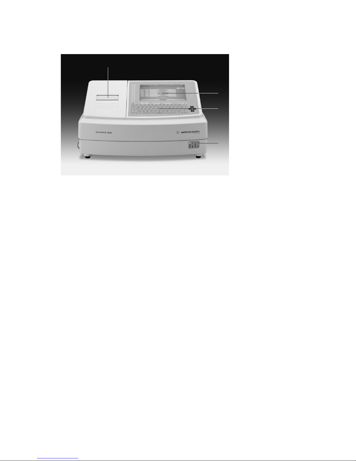
2.1 Overview: Sartocheck® 3 plus
Fig. 2-1 | Overview
Device figure
1 printer
2 display
3 keypad
4 Status LEDs
!
1
2
3
4
Page 7

7
2.3 Technical Data
2.3.1 Dimensions and Weight
Sartocheck
®
3 plus
Length: 460 mm
Width: 390 mm
Height: 212 mm
Weight: 13 kg
Packing Weight: 2.7 kg
2.3.2 Connection Data
Sartocheck
®
3 plus
Power requirements
Operating voltage: 100-240 V/±10%
Number of phases: 1 Ph/N
Neutral conductor: Loadable N (in the Appendix)
Grounding conductor: Separate SL (yellow-green) (in the Appendix)
Frequency: 47-63 Hz
Protection rating: IP 44
Installation: According to VDE regulations
Allowable voltage fluctuation: ± 10% from normal value
Maximum operating pressure: 10 bar g
Operating pressure: min. 4 bar g
Maximum power input: 74 Watt
Internal limit pressure: 10 bar g
2.3.3 Pneumatics
Sartocheck
®
3 plus
Required compressed air 4–9 bar g
Water, oil and particle free
2.3.4 Test Media
Sartocheck
®
3 plus
Test gas: Compressed air, dehydrated and deoiled
Wetting fluid: Water or as described with the process
validation documents for the filter cartridge
to be tested
Page 8

2.3.5 Product-Specific Data
Manual input range
upstream system volume 0
*1)
–100000 ml
*1)
When 0 is input, the upstream
system volume is measured.
Measuring Ranges
– Test pressure: 100–8000 mbar
– Pressure drop: 1–2000 mbar
– Max. measur-
able volume: 100000 ml
– Diffusion: 0.1–999.9 ml/min
– Water
intrusion: 0.1–999 ml/10 min
– Water flow: 0.01–99.9 ml/min
– Bubble point: 100–8000 mbar
Measuring Accuracy
– Pressure ± 0.1% ± 9.5 mbar
– Pressure drop ± 1 mbar
– Net volume
measurement ± 4%
– Diffusion ± 5 %
– Water
intrusion ± 5%
– Bubble point ± 50 mbar
Operating Conditions
– Room
temperature +15°C to +35°C
– Rel. humidity 10-80%
Display
– Size 8.4"
– Resolution 640 + 480 pixels
Data Output
– Service TU RS232 | RS485
– Service MU RS232
8
2.3.6 Test Methods
Test method Without ext. ref. tank With ext. ref. tank
Press. drop test: All filter systems up to net volume of 100 l
Diffusion test: Cartridge systems up to Cartridge systems up
net volume of 9000 ml net volume of 100000 ml
Bubble point test: Small systems and cartridge Small systems and cartridge
systems up to net volume systems up to net volume
of 9000 ml of 50000 ml
Multipoint diffusion Cartridge systems up to –
test: net volume of 9000 ml
Diffusion and Cartridge systems up to Cartridge systems up to
bubble point test net volume of 9000 ml net volume of 50000 ml
(complete test)
Intrusion test, Cartridge systems up to –
water flow test net volume of 9000 ml
2.3.7 General Data
Ambient conditions
Ambient
temperature: +5 up to
+35°C
Noise level: < 70 dB
Humidity: 95% at 25°C
The stated values apply from sea
level up to 2000 m.
The unit should be set up under
ambient conditions that produce
no negative effects during operation and processing, e.g. from
contaminated airflows, metallic
dust or fluids from leaks, condensation, aerosols or widely changing
temperature conditions.
!
Page 9

3.1 Notes|Explanations
Operating instructions
are binding;
the symbol is framed and
designated by a “book”.
Warnings
are framed and designated by
a “Hazard” triangle.
Electrical Hazards
are framed and designated by
the symbol to the left.
Notes
are framed and designated
by a “Hand”.
Grounding Conductor Connection
Is designated by this symbol at the
connection sites.
Mandatory Instructions
For handling electrical plug
connections.
9
3 Safety
The information contained in these
operating instructions applies to the
Sartocheck
®
3 plus, item no. 16290.
The manufacturer’s label is affixed
to the rear panel of the unit.
Important:
if you have any questions
Always have the following
information ready:
– Model
– Version
– Serial number
Having the right information
readily available will ensure correct
and quick processing.
!
Fig. 3-1 | Device identification Sartocheck® 3 plus
3.1.1 Device Identification
Page 10

10
3.2 Integrated Safety Devices
The installed safety equipment
must be inspected at regular test
intervals (d = daily, w = weekly,
m = monthly). The test methods
used are: S = sight inspection,
F = functional testing.
The unit has the following safety
equipment installed:
Line Disconnector
The unit is disconnected from the
mains voltage by switching off the
unit or when the unit is unplugged
from the wall outlet (mains supply).
Housing
All unit-specific components are
shielded against external influences
by a plastic housing. It is strictly
forbidden to disengage or dismantle the safety equipment. The function of this safety equipment must
be inspected and tested according
to the instructions given in the
Chapter “Maintenance”.
The operator is responsible for
instructing the operating personnel
and service and maintenance personnel about the meaning and the
function of the safety equipment.
These operating instructions are an
integral part of the unit and must
be available to operating personnel
and service and maintenance
personnel at all times.
The safety precautions and
warnings contained herein must
be observed.
3.3 Safety Measures
(to be performed by the operator)
The operator must
– Instruct his operating and servicing
personnel in the use of the filter
cartridge housing’s safety devices
and
– Ensure that the safety precautions
are complied with.
– The customer must prevent unau-
thorized persons (not operating and
servicing personnel) from access to
the filter cartridge housing danger
zone.
These operating instructions
must be kept in a safe place for
future reference. The frequency
of inspections and checks must
be observed.
The work described in these operating instructions is explained in such
a way that it can be understood
by trained workers and qualified
technicians.
Definitions Adapted from
EN 60204-1:
Trained Worker
A person familiarized with and, if
applicable, trained in his particular
duties by a qualified technician
and instructed about the potential
dangers in the event of improper
conduct and on the necessary safety
devices and safety precautions.
Qualified Technician
A person who, by virtue of his
technical training, know-how,
experience and knowledge of
relevant standards, is able to
assess the work assigned to him
and identify potential dangers.
3.4 Obligations of the Operator
In the European Economic Area
(EEA), the laws transposing Council
Directive (89/391/EEC) as well
as the corresponding individual
Directives and specifically including Council Directive (89/655/EEC)
concerning the minimum safety and
health requirements for the
use of work equipment by workers
at work into national law in their
respectively valid versions must be
observed and compiled with.
In Germany, the Operational Safety
Regulation dated October 2002
must be observed (regulation
transposing the above-mentioned
Directives into national law).
The operator must obtain a local
operating permit and follow the
regulations and restrictions set
forth therein.
Additionally, the operator must
comply with the local rules and
regulations for:
– The safety of the personnel
(accident prevention regulations)
– The safety of the work equipment
(protective gear and equipment and
maintenance)
– Product disposal
(Waste Management Act)
– Material disposal
(Waste Management Act)
– Cleaning
(cleaning agents and disposal)
and the environmental rules and
regulations.
3.5 Safety Tests Performed by the
Manufacturer at the Factory
Testing and inspection according
to DIN EN 61010-1
!
Test
Interval Method
m S
Test
Interval Method
m S/F
Page 11

11
4 General Warnings
4.1 Hazards
The safety systems and safety
notes described in these operating
instructions should be complied
with accordingly.
Keep the work area of the filter
cartridge housing free of objects
during operation so that unimpeded
access is possible at all times.
Before any installation, servicing
or repair work is carried out, make
sure you are aware of the electrical
hazards!
Unplug the equipment from the
wall outlet (mains supply) before
opening it!
Observe the required operating conditions, especially with regard
to the temperature of the medium.
It is transmitted to the components.
Touching components or contact
with the medium can result in
burns or scalding.
Wear suitable protective clothing
if necessary. Don’t forget that the
components of the filter cartridge
housing store heat and cool down
slowly.
4.2 Operating and Maintenance
Personnel
Operating personnel and service
and maintenance personnel are
persons who are responsible for the
transport, installation, operation,
equipping, maintenance and cleaning as well as troubleshooting on
the unit.
1. The unit may only be operated
by trained and authorized persons in accordance with operating
instructions that have been issued
by the operator.
2. The responsibilities for operation
of the unit must be clearly set
down and observed so that no
ambiguities arise with respect
to safety.
3. The safety precautions and
warnings given in the operating
instructions must be complied
with when carrying out any work
(operation, maintenance, repairs
etc.).
4. The operator shall never work in
any way that could impair the
safety of the unit or him| herself
or others.
5. It is the responsibility of the
operator to ensure that only
authorized persons work on
the unit.
6. It is the responsibility of the
operator to report immediately any
changes occurring on or to the unit
to the operating company.
7. It is the responsibility of the
operator to ensure that the unit is
only operated in perfect working
condition.
4.3 Inserting Replacement and
Wearing Parts
We must expressly draw your attention to the fact that replacement
parts and accessories that not have
been supplied by Sartorius Stedim
Biotech GmbH have not been tested
and approved by Sartorius Stedim
Biotech GmbH. The installation of
and|or the use of such products
can therefore have a negative effect
on the design properties of the unit
as constructed.
Sartorius Stedim Biotech GmbH is
not liable for any damages resulting
from the use of non-original parts
or non-original accessory parts.
Standard parts can be purchased
from specialized dealers.
4.4 Switch-off Procedures
The following shutdown procedure
must be followed before any
cleaning, servicing or repair work
is carried out.
1. Line disconnect
Turn off the main switch by pulling
out the AC adapter of the mains
supply.
2. Compressed air supply
Turn off the compressed air supply
and vent system.
Personnel may suffer physical injuries or fatalities if this procedure is
not followed!
!
Page 12

12
5 Installation
5.1 Delivery Scope
5.2 Goods Acceptance
Incoming inspection:
– Check the shipment for damage!
– Check the shipment against the
delivery note to ensure that it is
complete!
Complaints
If the shipment was damaged
during transit:
– Immediately contact the carrier!
– Keep the packaging material (in
case the carrier wants to inspect it
or the shipment has to be returned
to us)
If the shipment is not complete:
– Immediately contact Sartorius
Stedim Biotech GmbH or the
Customer Service Department in
your country!
If the delivery has other defects:
– Immediately contact Sartorius
Stedim Biotech GmbH or the
Customer Service Department in
your country!
The following are included in
the delivery scope of the Sartocheck
®
3 plus:
1. Filter integrity tester
Sartocheck
®
3 plus, item no. 16290
2. Operating instructions and
technical documents
3. Accessories (not shown in
the picture)
– Tubing “Inlet” with compressed
air filter (I.D. = 6 mm)
Order no.: 18104
– Tubing “Outlet”
(I.D. = 4 mm) Order no.: 18103
– Spare ink ribbon cartridge
Order no.: 6982141
– Spare roll of printer paper
Order no.: 6982142
– Country-specific power cord
Packaging for Return Shipment
Use the original packaging and
original packaging material as far
as possible.
If the original packaging and
original packaging material are
no longer available:
– Commission a packaging company
with specialized technicians.
– Pack the unit in a shipping
container in such a way that
mechanical damage is prevented.
If you have any questions about
packaging and transport securing
devices, please contact Sartorius
Stedim Biotech GmbH.
Check the equipment supplied
against the delivery note.
Please report incomplete deliveries
immediately to the shipping carrier
or the supplier.
Interim Storage
The external packaging of the unit
and its spare and replacement parts
is designed for a storage period of
three months from delivery.
Units kept in interim storage must
be stored in a closed, dry room at
temperatures from +5°C to max.
+50°C.
Fig. 5-1 | Sartocheck
®
3 plus
1 2
Page 13
13
5.3 Setup Instructions
5.3.1 Environmental and Site Conditions
Select a place of installation that
meets the following conditions:
– no significant heat irradiation from
heating or sunlight
– no strong airflows
– no chemically aggressive
environment
– no significant shocks
– no dust impingement
– no significant impingement of
humidity
5.3.2 Transport and Unpacking
The unit and its accessories are
packaged according to the national
custom and protected against
impacts. To avoid damaging the
equipment, please comply with the
following notes and instructions:
– Please observe the Technical Data
in Chap. 3.
– Please observe the weight.
For transport to the unpacking site,
use a floor truck if appropriate.
– To prevent the unit from slipping,
it should always be carried or lifted
by two people.
– To open the packaging, remove the
unit and place it on a workbench
or table intended for that purpose.
– The workbench or table must be
level and able to bear the appro-
priate load. Allow sufficient space
around the workbench or table
for the operator to work.
– Unpack the accessories and
technical documents and put them
in a safe place.
– Moisture in the air can condense
on the surfaces of a cold unit
whenever it is brought into a
substantially warmer place. If
you transfer the unit to a warmer
area, make sure to condition it for
about 2 hours at room temperature,
leaving it plugged into AC power.
The positive temperature differ-
ential between the inside of the
unit and the ambient environment
essentially protects the unit against
humidity and moisture.
Open the packaging carefully. It is
a good idea to save the packaging
material (in case the carrier wants
to inspect it or the shipment has
to be returned).
Dispose of packaging materials
in compliance with prevailing
environmental safety regulations.
5.4 Connections
Before starting up the unit; make
sure that the unit is stable and
secure. Check all pneumatic and
electrical connections on the unit.
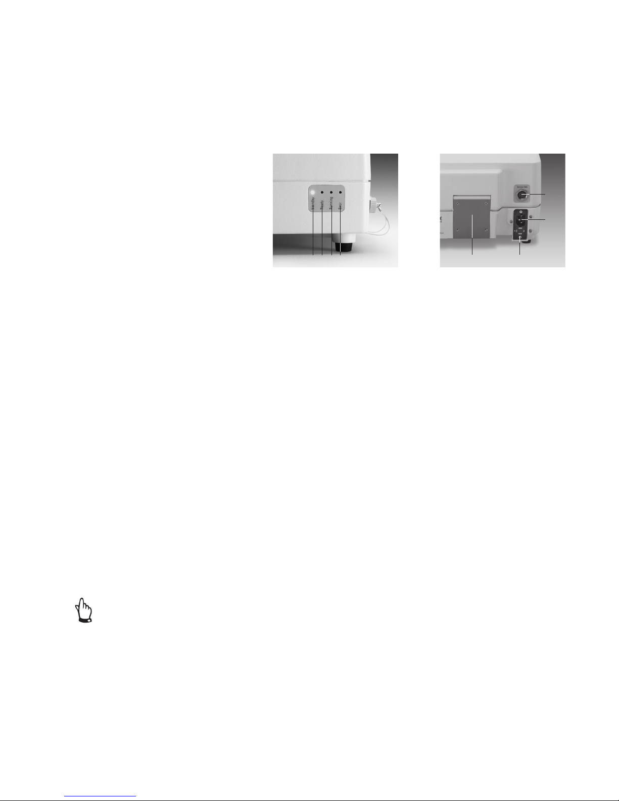
5.4.1 Front Side and Back Side
Fig. 5-2 | Front Panel
The following displays are located
on the front panel:
1 Standby
Is lit up when Sartocheck
®
3 plus is
ready for operations, but not currently running any test program.
(Blinking LED)
2 Ready
Lights up when the result of the
filter test is ready. (LED lit)
3 Running
Is lit up when a test is currently
running. (LED lit)
4 Error
Lights up when the test unit has
identified an error and cancelled the
filter integrity test. (LED lit)
Fig. 5-3 | Back Panel
The following connection ports
are located on the back panel:
1 Housing ventilator
In the device, there is a ventilator
which ensures a constant temperature in the Sartocheck
®
3 plus.
2 Service MU
Only Service function
(software upgrades)
3 AC adapter
Power plug for connecting the
power cord to mains supply.
4 Fuses
Fine-wire fuses between unit
and mains supply.
1 2 3 4
1 4
3
2
Page 14
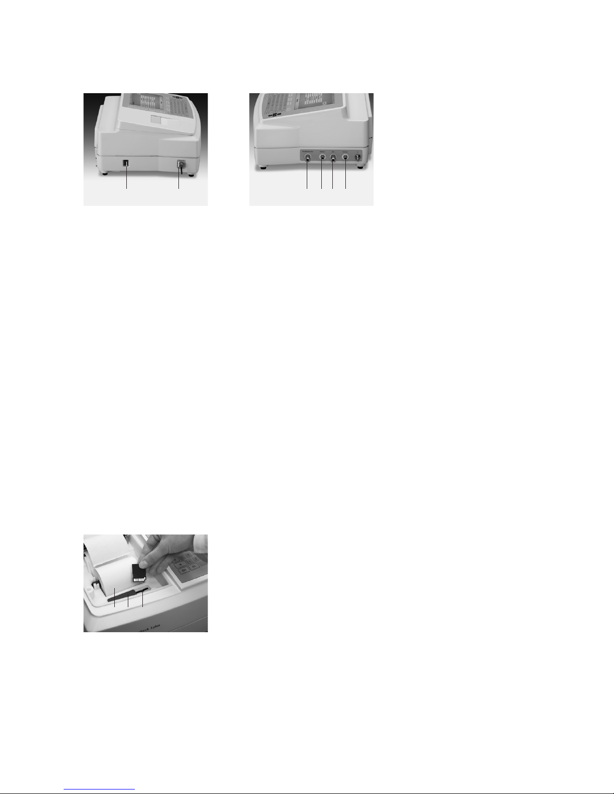
Fig. 5-4 | Left panel
Located on the left panel:
1 Main power switch
Switch on the power with the
main power switch.
2 Service TU
Only Service function
(software upgrades)
Fig. 5-5 | Right panel
Located on the right panel:
1 Ext. reference tank
Quick-release fastener for external
reference tank.
2 Venting 1
Outlet for ventilation 1
3 OUT
Quick-release fastener for test tube
4 Venting 2
Outlet for ventilation 2
5 IN
Quick-release fastener for
compressed air supply
14
5.4.3 SD card reader description
Fig. 5-6
1 SD card reader
2 cover
3 paper roll
1 2 3 4 5
1 2
123
Underneath the printer cover, there
is an SD card reader which can be
used for saving the test programs.
To prevent contamination, the
cover should be moved over the
opening (dust protection).
Do not remove the SD-Card during
the process of reading or writing.
5.4.2 Left and Right Device Sides of the Sartocheck
®
3 plus
Page 15

15
5.5 Connections With Internal
Pressure Sensor
The Sartocheck
®
3 plus can be
operated with an internal pressure
sensor and with various tube connections. The tube connections for
the Sartocheck
®
3 plus are shown in
Fig. 5-7 and Fig. 5-8.
Attention!
Do not connect Sartocheck
®
3 plus
to pressurized or high temperature
systems! Wait until the whole
system is at room pressure and
temperature!
Inlet Pressure During Operation
with Internal Pressure Sensor
The minimum operating pressure
required depends on the test method selected, but should be
at least:
> 4000 mbar and > 500 mbar
above the test pressure or above
the max. B.P. entered.
Check to make sure that all inlet
and outlet pressure tubing is connected properly, that all electrical
connections have been correctly
installed, and that the paper roll
as well as the ribbon cartridge
have been inserted.
Fig. 5-7 | Connection with internal pressure sensor
Fig. 5-8 | Connection with internal pressure sensor and external vent
Sartocheck® 3 plus
Sartocheck® 3 plus
Page 16

16
5.6 Replacing the Paper Roll and
the Ink Ribbon
To replace the paper roll, first
remove the printer cover by pushing
it backwards on the device. After
the cover has moved out of the
locking mechanism, it can easily be
removed by lifting it upwards.
Push the spindle into the hole in
the paper roll and insert the roll in
such a way that the spindle lies in
the holding device provided. The
paper must be fed on the lower
side backwards towards the print
unit. Feed the start of the paper
strip from the front directly into the
opening of the printer and briefly
press the "Paper" key. The paper
now feeds automatically through
the printer, along the ink ribbon,
and re-emerges from the top of the
print unit.
Now feed the printer paper from
the back|below through the slot in
the printer cover to its upper side so
that the paper re-emerges from the
device under the transparent cover.
Now replace the printer cover
on the device by feeding it from
above|behind onto the device and
pushing it from the back towards
the front until the cover slides into
the locking mechanism provided.
To replace the ink cartridge, the
printer cover must also be removed.
Afterwards, the black unit with
the ink ribbon can be removed by
pulling it upwards on its right side
(label "Lift"). The new ink cartridge
can then be reinserted in the opposite sequence and the printer cover
can be closed again.
Make sure that the spindle of the
paper roll is correctly positioned in
the holding device provided.
Otherwise, the paper roll may jam
during the printing operation.
Page 17

17
Sartocheck
®
3 plus
1. printer
2. display
3. keypad
4. LED status lights
Fig. 6-1 | Overview
6 Functionality
6.1 General Functional Description
The Sartocheck® 3 plus is a
qualifiable filter integrity tester and
consists of a management unit and
a test unit.
The test unit is a mechanically,
pneumatically and electrically
closed functional unit.
A test unit cannot be operated
directly by the user, but is 100%
controlled by the data management
unit via an internal RS 485 interface. With the help of its electrical
and pneumatic peripheral devices
the data management unit performs
the actual filter tests along with a
series of other additional functions.
Filter Integrity Test
The main purpose of Sartocheck
®
3
plus is to test the integrity of membrane filters according to various
methods.
6.2 Test Programs
In the test program, the procedural
steps and the parameters are set
down for the filter integrity test.
A programmed test program can
be loaded into the test unit and
the test will be run independently.
– Loading a test program
– Run a test program
The test unit runs through the
previously loaded test program, in
other words, it carries out the filter
integrity test and saves the result
in non-volatile memory. The data
management unit monitors the
progress of the filter test, i.e. it
reads in the current data in order
to present them to the user.
6.3 Management of the Test Results
In the management unit of the
Sartocheck
®
3 plus, the measured
raw date (the test results) are processed further, i.e. the units are
recalculated and the numbers are
converted into text.
6.4 Functionality Test
With the function test, the user
is able to interactively test the functionality of pneumatic
components. The proportional
valves are not explicitly, but
rather implicitly tested in this
context.
6.5 Cleaning
Sartocheck
®
3 plus starts the
procedure for cleaning and flushing
the internal lines and the volume
reference tank.
1
2
3
4
Page 18

18
6.13 Serial Number
Every unit bears its own unique
serial number. The serial number
may not be changed during a
software update.
– The serial number is entered for
the first time during production
of the unit.
– If the PCB has to be replaced
during repairs that may arise later,
the unit must be assigned the
exact same serial number that is
imprinted on the manufacturer’s
label.
6.6 Self-Test for Broken Conductors
and Short-Circuiting
While controlling the valves and
sensors, the Sartocheck
®
3 plus
hardware can check whether there
are any broken conductors or
short-circuits.
6.7 Calibration
The calibration function is used
to calibrate the internal pressure
sensor with the aid of more precise
reference measuring devices and to
adjust it if necessary. Each sensor
runs its own calibration date.
An adjustment routine automatically follows the test. The test can
also be activated separately.
Sartocheck
®
3 plus saves the raw
data for the calibration record in
permanent memory.
The operator can use the following
sensor types for determining the
reference pressure:
– Absolute pressure sensor:
The reference pressures are measured directly.
– Relative pressure sensor:
The measured reference pressures
relate to the ambient pressure. The
ambient pressure must be known or
measured with additional reference
measuring equipment.
6.8 Internal Pressure Sensor
Sartocheck
®
3 plus sets either 6 or 8
pressure values and compares them
with the internal pressure sensor
and the pressure values measured
on the reference measuring instrument (connected to the “OUT”
connector) to calculate scale and
linearization.
6.9 Pressure Gauge Function
In the pressure gauge function,
the Sartocheck
®
3 plus behaves
like a digital pressure measuring
device. To do so, it uses the internal
pressure sensor.
6.10 Cleaning|Drying
Through the pneumatic connectors, Sartocheck
®
3 plus is able to
flush almost all internal volumes.
The user is responsible for ensuring
that no damage occurs to any components of the Sartocheck
®
3 plus
due to the pressure built up by the
pump used in the cleaning.
6.11 Safety Functions
– As one of its technical options,
Sartocheck
®
3 plus runs the test
step Initialization| Security Status in
the event of a power failure. Basically, what this step does is close
the compressed air supply and the
block valve to the filter housing.
– Sartocheck
®
3 plus is not responsible for ensuring whether the maximum pressure for the compressed
air supply to the filter housing is
too high. That means the user must
make sure that the initial pressure
cannot damage the filter housing.
6.12 Software Update
The operating software on
Sartocheck
®
3 plus is updated
with a corresponding program run
exclusively with an external Laptop
(via the jacks Service MU| Service
TU). Since the configuration data
are localized in a battery-backed
RAM, they remain unchanged
during any software update.
Page 19
19
7 Operation
Picture of Sartocheck® 3 Plus
1 printer
2 display
3 keypad
4 status lights
Fig. 7-1 | Overview
7.1 Switching on the device
1
2
3
4
Page 20

General operating concept
The Sartocheck
®
3 plus can be
operated using the keypad and the
various function keys. In general,
the menu is structured so that
the respective menu items can be
selected using the function keys to
the left and right next to the display. Alphanumeric entries can be
made via the keypad. Menu items
for which the alternative contents
have already been set (e.g. Yes or
No) can be changed by pressing
the associated function keys several
times.
The Sartocheck
®
3 plus has an internal memory to store user-specific
settings and programmings (e.g.
test programs). There is no electronic results database. Only the last
test result is retained in the memory, so that it can be printed out
again if necessary. This means that
the Sartocheck® 3 plus is a purely
paper-based system. The requirements with respect to 21 CFR Part
11 are therefore not applicable to
this tester.
To be able to archive test programs
or switch between different testers,
an SD card reader is integrated.
This is located under the printer
cover and can be used for standard
SD cards (max. 2 GB).
20
The display and control panel
features the following operating
elements:
1 Esc
Press this key to cancel the current
procedure.
2 F1-F 10
The function keys F1 to F10
correspond to the function types
shown on the display.
3 Log on
When pressed, the logon screen
is activated.
4 Log off
Press this key to log the current
user off.
5 Function keys (unlabelled)
The unlabelled function keys
located to the right of the display
are used to select the menu items
appearing directly adjacent to the
keys on the display during operation.
6 Cursor keys
The cursor keys labelled with arrows
can be used to navigate in the
menu.
7 Paper
This key advances the paper in the
internal printer.
8 PC keypad
Is used for inputting and starting
processes.
9 Home
When this key is pressed, programming is cancelled without saving.
The former test is reinstated and
the user is automatically taken back
to the Main Menu.
10 End
Press this key to jump to the end
of the input line when entering
parameters and data.
7.1.1 Operating Elements
Fig. 7-2 | Display and control panel
7
8
9 10 432
1
6
5
Page 21

21
Fig. 7-3 | Login menu
Fig. 7-4 | Main Menu
7.2 Switching the device ON and OFF
If you want to switch the unit on, proceed as follows:
Before you switch on the power supply and the compressed air, compare the
connection data for the unit (see the Chapter 01 Technical Specifications) with
the data for the mains current and the compressed air supply.
Connect Sartocheck
®
3 plus to the mains supply by plugging the power cord into
the wall outlet, install all tubing connections. The unit is now ready for operation.
Login menu
User ID: Enter operator’s name
Password: Enter operator’s password
OK: Confirm correct entry
Cancel: Delete entry
Important Note: When Sartocheck
®
3 plus is delivered it is factory set for
the following user:
Name: mentor
Password: mentor
Every operator must log-in before he can activate the Main Menu.
The operator logs in by pressing the “Login” key on the keypad. After pressing
the “Login” key, the user will be asked for his name and password. If both are
correct, then the keypad is activated for use. When the operator stops working
with Sartocheck
®
3 plus, he must always log out by pressing the “Logout” key.
Sartocheck
®
3 plus is then blocked for further operation until another operator
logs in.
Please note that a running integrity test is aborted if the “logout” key is pressed.
Information line with model, version, system number and user name.
Menu display: Main Menu
F1- F8: Select the function menus with the function keys
Help: Selects the Help Menu
Selects the function menus
The Main Menu appears.
– Before starting a test, allow the unit to warm up for about 20-30 min.
For shut-down times < 30 min and constant ambient temperatures, the warm-up
phase can be shortened accordingly. For more information about the tests, see
Chapter 7.3 ff.
– Program the data for the test execution.
– The Sartocheck
®
3 plus is ready to be started (by the registered user).
– Start the test.
Only service technicians or trained personal may install connections and start up
the unit!
Page 22

7.2.1 Test Execution
Run the test according to the test
procedure that you selected and
programmed.
7.2.2 Switching Off the Device
When switching off the unit,
proceed as follows:
–
Run through the test to the end.
–
Close the compressed air intake on
the compressed air supply.
–
Run the log-off function.
–
Turn off the main switch.
7.2.3 Switching off the Device on the
Failure of the Power Supply
In the event of a power failure, all
valves will be switched to a secure
state. This guarantees that the filter
housing is vented. The ongoing test
is cancelled. No test result will be
available.
Loss of Compressed Air
In the event that the compressed
air supply stops, the test is automatically cancelled and an error
message appears. “Target pressure
not reached”. The system is vented
automatically. When the supply
of compressed air resumes, the
unit must be restarted and the
test repeated.
7.3 Tests
7.3.1 Test Conditions
To obtain reliable and reproducible
test results, observe the following:
– Run the integrity test at room
temperature (approx. 15–30°C),
whenever possible.
– During an integrity test run, always
avoid any temperature changes.
– The upstream side of the filter
system must be absolutely leak-free
(Run pressure hold test).
– Do not connect the integrity tester
to pressurized systems.
– If you wish to use other types of
compressed gas and|or wetting
fluids not specified by Sartorius
Stedim Biotech, consult your local
Sartorius Stedim Biotech office or
Sartorius Stedim Biotech Technical
Support (see Chap. 8.1)
– For the Water Intrusion Test,
the surface tension of the water
must be > 70 dyn/cm.
– Always enter correct test param-
eters. Incorrect test parameters will
lead to incorrect test results or
erroneous evaluations.
Reference Pressure
On delivery, the Sartocheck
®
3 plus
is set to a reference pressure of
1000 mbar.
Calibration
The integrity tester should be
re-calibrated at least once a year,
twice being preferable.
7.3.2 Test Selection
With the Sartocheck
®
3 plus, you
can directly select a particular
integrity test method. This greatly
simplifies programming the data
for a test, since only the parameters
that are relevant for the selected
test are displayed.
You can select any of the following
test methods:
Test Methods
1 Diffusion Test
2 Bubble Point Test
3 Diffusion Test and Bubble Point
Test (complete test)
4 Water Intrusion Test
5 Water Flow Test
6 Pressure Drop Test
7 Multipoint Diffusion Test
8 Volume Measurement
9 Customer-Specific BP
10 Customer-Specific Multipoint
Diffusion Test
System Venting
At the end of each test, after a
power failure or after switching
off the unit during a test, the
system is automatically vented.
22
Page 23

23
7.3.3 Programming the Test (F2 – Main Menu)
The test parameters of the individual tests on the Sartocheck
®
3 plus are entered or
selected using the keypad. The Main Menu is the starting point for programming.
The following example uses a diffusion test to illustrate how to program data for
tests and running test sequences (F2 – Main Menu). The programming and test
sequences are identical for the other test types.
Before we start with the programming, let’s first explain a few important key
commands.
The Sartocheck
®
displays are set up with yellow buttons located on the right side
of the screen. These buttons always have the same functions:
Help: Starts the Online Help function
Main Menu: The program jumps back to the Main Menu (see Fig. 7-5)
Page Up: the program scrolls to the previous page of the screen
Page Down: the program scrolls to the next page of the screen
List Up: Whenever a list is displayed on the screen, use LIST UP
to scroll up the list
List Down: Whenever a list is displayed on the screen, use LIST DOWN
to scroll down the list
Enter: Confirms the selected function, action or entry.
Following confirmation, the yellow key turns gray
The respective functions can be activated using the unlabelled function keys to the
right of the display.
Programming Tests
Select the programs in the menu “Programming tests: Program selection”.
Already existing programs can be selected by entering the program number in the
field provided for this purpose above the list or by marking. The selected line is
highlighted in blue. Scroll back and forth in the program selection list with List
DOWN|UP. Confirm the selected program line by pressing Enter. The Enter key
turns gray. If you would like to correct the program memory location, select a new
line number or highlight the new line directly on the touch screen.
Re-confirm by pressing Enter. Press PAGE DOWN to scroll to the next page.
The diffusion test is used as an example.
7.4 Diffusion Test
When pressure is applied to the upstream side of a wet filter, a diffuse gas stream
starts to flow through the filter membrane after a short time. The diffusion is
dependent on the effective filter surface, among other things. The diffusion test
is not suitable for testing disk filter systems. However, the diffusion test is a very
well suited test method for the integrity testing of medium-sized and larger filter
cartridge systems starting from approx. 150 cm
2
. The diffusion value refers to a test
pressure, which means there is a direct correlation to the actual retention behavior
of the filter (for a more detailed description see Chapter 12, Appendix).
In the menu “Programming tests: Program selection”, the test type is selected.
– Select test type (standard test or user-defined test)
Fig. 7-5 | Main Menu
Fig. 7-6 | Programming tests:
Program selection
Fig. 7-7 | Programming tests:
Program selection
Page 24
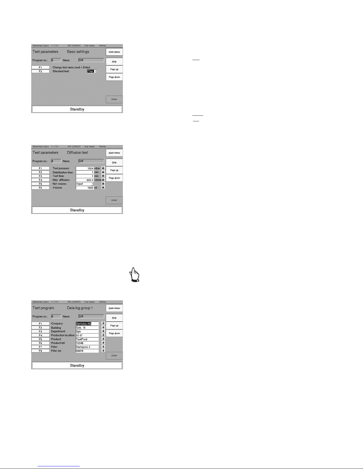
24
Test Parameters
Enter external connections
Standard test: Yes|No
In the menu “Test parameters: Basic settings,” parameters of the configuration are
entered. The function keys are used there to enter the appropriate settings.
The parameters for the standard test are defined in the configured Service Menu.
Unlike the defaults (standard values), the values can be individually adjusted.
For the diffusion test, you have the following options:
Pressure unit: mbar|psi| hPa
Automatic test mode: No|Yes
Enter parameters for the diffusion test
Test pressure: from 50-8000 mbar
Stabilization time: in min.
Test time: in min.
Max. diff.: in ml/min
Net volume: in ml
In the menu “Test parameters: diffusion test,“ the parameters for the diffusion test
are entered with or without net volume measurement.
For tests with volume measurements:
– Test pressure
– Stabilization time
– Test time
– Max. diffusion
When conducting tests without volume measurement, net volume should be
entered separately.
The test parameter data can be found in the validation or data sheets documents of
the respective filter cartridge.
Locks
The locks are activated for the test parameters (default). After entering with
the Shift + F keys, the programmer can lock the data to prevent any changes.
The dialog boxes are then highlighted in gray. The user can no longer change
the entered data.
Enter record data 1
Company: Company name
Building: Building name; house number
Department: Identification of the department
Production site: Production sector
Product: Product name
Product lot: Batch number
Filter: Filter size
Filter lot: Number of the filter batch
Fig. 7-8 | Test parameters:
External connections
Fig. 7-9 | Test parameters:
Diffusion test
Fig. 7-10 | Test program: Log data 1
Page 25

25
Entry of record data 2
Filter line: Name of filter line
Housing: Type of housing
Wetting medium: Type of wetting medium
Test gas: Type of test gas
Water quality: Data on water quality
Comment: Name of operational process
Comment 2: Enter test-relevant remarks
Comment 3: Enter test-relevant remarks
Start the Test Program
Save:
After confirmation, the data are saved
The menu “Test program: Start” lists the options for that test start.
Once the programming is finished, the test can be started.
(Pressing “Page Down”)
Fig. 7-11 | Test program: Record data 2
Fig. 7-12 | Test program: Start
Page 26
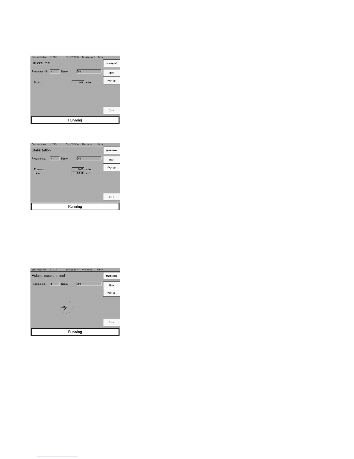
26
The test sequence is structured as follows:
Pressurization
Sartocheck
®
3 plus adjusts the pressure to the pre-programmed test pressure.
After a short waiting period during which the system is tested for major leakage,
the program goes into the stabilization phase.
Stabilization Phase
During the stabilization phase, the test pressure is adjusted to the exactly desired
value. Fluctuations in test pressure occur as a result of cartridge compaction and
temperature variations created by the different filter housing temperatures and
the downstream air flowing in from the compressed air supply.
These fluctuations in test pressure are compensated for during stabilization.
About half of the stabilization time is utilized to carry out volume measurement
(when volume measurement is selected).
Test Phase
In the test phase, the system is in a closed state, i.e. no compressed air is pumped
into the filter housing. This means that no medium (compressed air) or energy
is exchanged (temperature air from the compressed air supply) with the ambient
environment. The pressure drop resulting from diffusion is measured over the test
time entered.
Volume Measurement
The display shows a clock when the volume measurement is performed.
Fig. 7-13 | Test: Pressurization
Fig. 7-14 | Stabilization
Fig. 7-15 | Volume measurement
Page 27

27
Volume Measurement
The volume is displayed in ml.
In the test phase, the current diffusion value is displayed as a graph and additionally
as a numerical value. The graph is designed so that the limit is drawn as a red line.
If the actual value is below this, the integrity of the filter is proven.
7.5 Bubble Point Test
In wetted membranes, the wetting liquid is held inside the porous structure by
capillary force. This force increases as the pore size decreases. A specific gas pressure
dependent on the pore size of the membrane is necessary to force out the liquid
from the pores. This pressure is generally designated as the “Bubble Point,” or
B.P. for short. It generally indicates the largest pores of a filter since liquid is first
expelled from them. Hence, it follows that the B.P. of a filter depends both on the
filter material (the contact angle varies from material to material) and, in particular,
on the surface tension of the wetting fluid. Low surface tensions, as are present
in organic solvents, detergents and emulsifiers yield low B.P.’s.
Since the surface tension also depends on the temperature, different wetting fluid
temperatures will also yield different B.P.’s. The Bubble Point Test is especially
suitable for checking the integrity of disc filter systems. (For a more detailed
description, see Chapter 12, Appendix).
Test parameters: Bubble Point Test
Enter the parameters: BP Min. in mbar
BP Max. in mbar
System test code: e.g. standard
Net volume: Enter or measure, if Enter: Volume in ml
Fig. 7-16 | Volume Measurement
Fig. 7-17 | Test Phase
Fig. 7-18 | Test parameters:
Bubble Point Test
Page 28

7.6 Diffusion Test and Bubble-Point Test (Complete Test)
This test method is a combination of the diffusion and the B.P. tests and is
predominantly used to check the integrity of membrane filters.
Test parameters: Diffusion and Bubble Point Test
Test pressure: in mbar
Stabilization time: in min.
Test time: in min.
Max. diffusion: in ml/min.
Min BP: in mbar
Max BP: in mbar
Net volume: Enter or measure, if Enter: Volume in ml
7.7 Water Intrusion Test | Water Flow Test
This test method is used exclusively to test hydrophobic gas filter elements. The
test sequence of this test method is the same as that of the Diffusion Test. However,
the Water Intrusion Test differs from the latter test in that the hydrophobic filter
element in the filter housing is flooded upstream with water to blind the filter so
that when a pressure gradient is applied, the water volume intruding into and
diffusing through the hydrophobic filter matrix per unit of time is calculated from
the pressure drop instead of the gas stream diffusing through the
membrane as in the Diffusion Test.
1. The Water Intrusion Rate: Indicates the rate calculated from the pressure drop,
test time and upstream volume (analogous to the calculation of diffusion).
2. The Water Flow Rate: Indicates the rate related to the water flow in the membrane
(Water Intrusion converted to “Water Flow”).
The Water Intrusion Test is suitable for all hydrophobic systems of approx.
1000 cm
2
filtration area and larger, all the way to process-scale systems.
(For a more detailed description, see Chapter 12, Appendix)
Test parameters: Water Intrusion Test
Test pressure: in mbar
Stabil. time 1: in min.
Stabil. time 2: in min.
Test time: in min.
Max. WIT: in ml/min
Net volume: Enter or measure, if Enter: Volume in ml
Remark
Stab 1 in the stabilization time before Netvolume determination. This time is needed,
in order to compact the filter system therefore to avoid misinterpretation.
Stab 1 should not set less than 3 min.
Stab 2 is the stabilization time before the water-intrusion (water-flow) measurement. The stab 2 value is available in the validation guide of the filter cartridges.
The standard value is 10 min.
28
Fig. 7-19 | Test parameters:
Diffusion + BP Test
Fig. 7-20 | Test parameters:
Water Intrusion Test
Page 29
29
Fig. 7-21 | Test parameters:
Pressure Drop Test
Fig. 7-22 | Test parameters:
Multipoint Diffusion Test
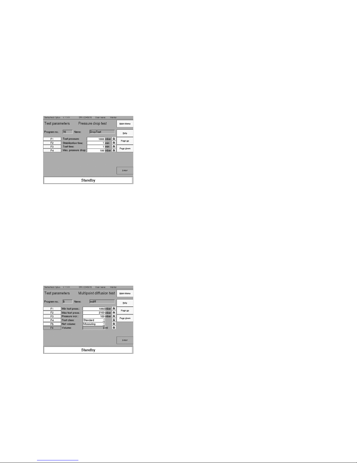
7.8 Pressure Drop Test
The Pressure Drop Test is based on the change in pressure within a filter system
connected upstream. This change is caused by the diffusive gas stream flowing
through a wet membrane at a given test pressure (see “Diffusion Test”).
The pressure drop measured in the process can be used as a direct measure of
the filter system’s integrity, provided that the upstream volume of the system
is constant and known. For this reason, a Pressure Drop Test is recommended
mainly to leak-test empty housings and pressure vessels with a known volume.
We additionally recommend that you carry out the following Pressure Drop Test
to check for major leakages. (For a more detailed description, see Chapter 12,
Appendix).
Pressure Drop Test
Test pressure: 3000 mbar
Stabilization time: 3 min
Test time: 3 min
Pressure drop: max. 3 mbar
Test parameters: Pressure Drop
Test pressure: in mbar
Stabilization time: in min.
Test time: in min.
Max. pressure drop: in mbar
7.9 Multipoint Diffusion Test
The multipoint diffusion test is based on the pressure dependency of the diffusive
gas flow through moistened filters. Starting at a given minimum pressure, the test
pressure is increased step by step up to the maximum value, or the bubble point,
and the diffusion is measured for each pressure increment. All values are output
by Sartocheck
®
3 plus in the form of a pressure| diffusion curve and a data table.
The slope of the curve allows changes in the filter material to be identified before
the next filtration run so that by comparing the curves obtained at the beginning of
the filter’s use, any defects can be detected before they can spoil an actual filtration
run. The Multipoint Diffusion Test is thus suitable as an additional test method for
verifying integrity test results.
Test parameters: Multipoint Diffusion Test
Min. test press.: in mbar
Max. test press.: in mbar
Pressure incr.: e.g. in 100 mbar increments
Test class: e.g. Standard
Net volume: Enter or measure, if Enter: Volume in ml
Page 30

30
7.10 Volume Measurement
This test method measures the net volume of the system (e.g. filter housing).
The Sartocheck
®
3 plus uses its internal or external reference tank pressurized to
the
programmed pressure to determine the unknown volume. This is not an integrity
test. Rather, this test enables net volume validation of vent filter installation for
water intrusion tests for instance.
Please contact Sartorius Stedim Biotech support before performing any net volume validation.
Enter test parameters: Volume Measurement
Test pressure: in mbar
Stabilization time: in min.
7.11 Customer-Specific BP
The normal bubble point test (as previously described) uses a standard set-up of
parameters to cover most of applications. However, some applications in which the
wetting fluid differs considerably from water (e.g. oily or viscous products) or in
which the filtration area is large (multi-round housings), bubble point detection can
be optimized using the customer-specific bubble point test.
Please contact Sartorius Stedim Biotech customer service, which will adjust your
Sartocheck
®
3 plus program to the optimal parameters for your application.
Test parameters: customer-specific BP
Start factor: Enter the factor
Prestabilization: in sec.
Stability by phase: in sec.
Phase test: in sec.
A1 Criterion : in ml/min
A2 Criterion : in ml/min
7.12 Customer-Specific Multipoint Diffusion Test
The normal Multipoint Diffusion Test does not determine a pass of fail result. This
Customer-Specific Multipoint Diffusion Test allows the user to enter a maximum
diffusion limit line. Up to eight (8) points can be used to define this limit line
(pressure vs. diffusion). During test execution the actual measured diffusion will
be compared to this limit line to determine a pass of fail result.
Fig. 7-23 | Test parameters:
Volume Measurement
Fig. 7-24 | Test parameters:
Customer-specific BP
Fig. 7-25 | Diffusion threshold value line
Page 31

31
7.13 Program Database (F4 – Main Menu)
All test programs created are saved in the program database.
Sartocheck
®
3 plus features the option to archive 250 user-programmable test
programs in its internal database. The program data in the program item “Program
database (F4)” can be managed.
The following functions can be selected:
F1: Load test programs from internal memory
All of the programs available in the Sartocheck
®
3 plus are displayed.
F2: Upload test program from SD card
You have the option of installing new programs in the Sartocheck
®
3 plus
(e.g. transferring from one Sartocheck
®
3 plus to another).
F3: Save backup to SD card
A copy of the program settings is saved to the SD card.
F4: Load backup from SD card
A copy of the test program settings is loaded from an SD card.
With F4 the test programs are stored in backup format.
This applies to the entire program database only. Individual programs cannot
be stored in backup format.
7.13.1 Test Program From Internal Memory (F1 - program database)
When loading test programs from internal memory, all test programs are displayed
in the program selection list. You can highlight the programs by entering the list
number (F1) in the fields provided for this purpose or via the function keys F2–F10
mark. There is an entry line “From ## to ##”above the program list. In this line,
you can highlight test program blocks (via F1).
Confirm your selection by pressing enter.
The highlighting can be removed with the button “Undo marking”.
The highlighted test program is displayed above the function keys F1-F4.
When test program blocks are highlighted, you can scroll through the selection
list with LIST UP|DOWN
You can select the following functions:
F1: View
Display the parameters predefined in the test program along with
previously defined record data.
F2: Print
Print out the test program on the internal printer
F3: Save to SD card
The test program is saved to the SD card
F4: Delete
Delete the test program
Fig. 7-26 | Program database
Fig. 7-27 | Program database:
Internal memory
Fig. 7-28 | Program database
Page 32

32
7.13.2 Uploading in the Test Program from the SD Card (F2 - Program Database)
Save SD card archived test programs back into the Sartocheck
®
3 plus program data-
base. To do so, insert an SD card into the drive of the Sartocheck
®
3 plus and press
PAGE DOWN.
The data on the SD card are uploaded and displayed in a program selection list.
Here you can select the programs as described (see Fig. 7-27: Program databases:
Internal memory).
After you have selected the program or the program block, you will be prompted
to assign a memory location number and|or memory location to this program or
program block in Sartocheck
®
3 plus.
The test program and|or the test program section will be uploaded and saved
to the selected internal program memory location.
Fig. 7-30 | Program database:
Load test program
Fig. 7-31 | Test program:
Assign memory location number
Fig. 7-32 | Program database:
Program space
Fig. 7-29 | Program database:
Load test program
Page 33

33
If the memory location number you have selected is already assigned, a warning
will be displayed. With PAGE UP, you can select a new program memory location.
By pressing Enter, the program data already stored in the internal memory will be
overwritten with the new data.
7.13.3 Saving a Backup of all Test Programs on SD Card (F3)
With the backup function, all test programs in the internal memory will be written
on a diskette (F3) and| or the test programs in the internal memory will be rewritten
(F4). Insert the SD card into the disk drive and then press PAGE DOWN.
Only use the backup function for saving data, not for archiving data.
The backup files can only be viewed with a Sartocheck® 3 plus, because a
Sartocheck® 3 plus-specific data compression method is used here. For archiving
your program files we recommend you use the (F1) function “Test programs from
internal memory” -> (F3) “Save on a SD card.”
You have to individually name your backup files.
Type in the backup file name and confirm by pressing enter.
Then all data in the program database will be written to the backup file.
If the backup SD-Card already contains a backup file, you must confirm that
the data will be overwritten before saving or cancel the backup routine.
Fig. 7-34 | Program database: Save backup
Fig. 7-35 | Program database: Save backup
Fig. 7-36 | Program database: Save backup
Fig. 7-33 | Test program:
Assign memory space
Page 34

34
7.13.4 Reading in the Backup of all Test Programs from the SD Card
(F4 - Program Database)
When reloading backup files, insert the backup diskette in the SD card drive.
If you want to save more than one backup file, open the backup selection list
where you can select the file you want.
When re-saving a backup file, all test programs in the internal memory are
overwritten with the backup files.
Load backup from network (F7) follows the same procedure as from a diskette (F6).
Fig. 7-37 | Program database:
Reading in the backup
Fig. 7-38 | Program database:
Reading in the backup
Fig. 7-39 | Program database:
Reading in the backup
Page 35

35
7.14 Visualization (F3 – Main Menu)
Generally, you can continue to work with the Sartocheck
®
3 plus (e.g. a new
program can be written) while a filter test is running in the background. If you then
want to get information about the current status of the running filter test, you can
display the current filter integrity test with the “Visualization” function.
7.15 Special Functions (F6 – Main Menu)
In the menu “Special functions” you will find Sartocheck
®
3 plus functions that are
not directly linked to filter integrity testing.
Here, the function tests for the management unit and the test unit are carried out.
The cleaning procedure and drying procedure for the internal pneumatic block and
internal volume reference tank can be selected here. Furthermore, pressure gauge
functions can be activated in the special functions menu. The user can change
his/her own password as long as he|she has access rights to this menu. For more
details, refer to the menu “Service user management”.
In the menu Special functions, the corresponding functions can be activated
with the F1-F6 keys.
7.15.1 Function Test of Management Unit (F1 – special functions)
With the function test MU (management unit), you can test the peripherals of the
Sartocheck® 3 plus.
F1: Printer function test
Print out all print characters in black and red on the internal printer
F2: Function test SD card
After inserting an SD card, you can select three different test procedures:
Read only|Check file format |Write and read
F4: Format SD card
Format SD cards
7.15.2 Function Test of Test Unit (F2 – special functions)
The TU Function test will check the pneumatic block. Here you are interactively
guided through a test menu in which all valves and outlet ports are individually
checked. Please follow instructions in the Sartocheck
®
3 plus display. Using the valve
diagram you will be able to identify immediately which valves are working properly.
The indicator lights next to the valve will light up green. In the event of an error
they will light up red.
Fig. 7-41 | Special functions
Fig. 7-40 | Visualize
Abb. 7-42 | Function test MU
Abb. 7-43 | Special functions:
Function test TU
Page 36

36
7.15.3 Cleaning (F3 – special functions)
To perform the cleaning and the drying cycle, you will need a Sartocheck® cleaning
kit (art. n° 16288---CK).
The cleaning menu allows you to flush all internal pneumatic parts completely,
from the valves to the internal reference tank.
The cleaning procedure is divided into 5 interactive steps. Sartocheck
®
3 plus will
guide you through each individual step. A diagram will show you which connections
are to be connected with the flushing tubing during the ongoing step.
After you have installed all the connections according to instructions, press the
start button. Sartocheck
®
3 plus then automatically carries out the current cleaning
step. At the end of cleaning, the drying menu is activated automatically. We recommend that you also carrying out a drying routine after every cleaning. This is done
to ensure that no detergent solution remains in the pneumatic block.
If drying is not performed after cleaning, a message stating that the drying cycle
has been cancelled will display every time a test is started. Once the drying cycle has
been completed, this message will no longer display.
Description of the connections:
a: IN – Inlet pressure tubing
Connect inlet pressure tubing
b: Venting 2
Connect this outlet as defined for each individual step
c: OUT – Outlet pressure tubing to the filter housing
Connect this outlet as defined for each individual step
d: Venting 1
Connect this outlet as defined for each individual step
e: Ext.Ref.Tank
Connect this outlet as defined for each individual step.
You will need a coded Stäubli connector, see accessories.
f: Rinsing fluid
Rinsing fluid, usually water
g: Ext. pump
Laboratory peristaltic pump or diaphragm pump
Power max: 1000 ml/min
h: Cleaning fluid
Cleaning fluid
The cleaning fluid we recommend:
Water (cold, warm or hot; never use warm or hot water for protein contamination!)
Buffer solutions, e.g. 0.9 % NaCl Solution
Sodium hydroxide solution, max. 1 M
In step 5, clean the entire pneumatic components, i.e. the pneumatic block and
the internal reference tank are flushed with water. This is done to ensure that no
detergents remain in Sartocheck
®
3 plus.
If you have not installed the connections in accordance with the diagram and the
procedure has already started, we recommend that you cancel cleaning and restart.
The pneumatic components can be damaged or their function impaired by improper
connection. Improperly connected tubing can also impair the effectiveness of the
cleaning procedure. Therefore cleaning should be restarted.
Fig. 7-44 | Cleaning
Fig. 7-45 | Cleaning
Fig. 7-46 | Special functions:
Function test TU
Fig. 7-47 | Cleaning
Page 37

37
7.15.4 Drying (F4)
After cleaning, drying follows. The drying program is structured analogously to the
cleaning program. Here too you will be interactively guided through the individual
steps. The diagram will show you how the connections should be produced.
Description of the connections:
a: IN – Inlet pressure tubing
Connect inlet pressure tubing
b: Venting 2
Connect this outlet as defined for each individual step
c: OUT – Outlet pressure tubing to the filter housing
Connect this outlet as defined for each individual step
d: Venting 1
Connect this outlet as defined for each individual step
e: Ext.Ref.Tank
Connect this outlet as defined for each individual step.
You will need a coded Stäubli connector, see “Accessories.”
f: Receptacle – Fluid holding tank
For collecting the fluid still remaining in the pneumatic block and internal
reference tank
Laboratory peristaltic pump or diaphragm pump
Power max: 1000 ml/min
During the drying cycle two (2) compressed air sources are required
(connections a & e)
7.15.5 Pressure Gauge Function (F5)
With the pressure gauge function, you can use the internal pressure sensor for
gas pressure measurement. For measurement with the internal pressure
sensor, the sensor (pressure gauge) is connected to the outlet. The remaining
pneumatic components are turned off. Now, Sartocheck
®
3 plus works like a digital
pressure gauge of accuracy class 0.1 and can be used to calibrate other pressure
gauges. During measurement with an external pressure sensor, Sartocheck
®
3 plus
operates like a digital pressure gauge of accuracy class 0.1 and can also be used
to calibrate other pressure gauges.
Do not use the pressure gauge function to monitor the pressure during
liquid filtration!
7.15.6 Changing Own Password (F6)
According to the settings for the password expiration date, the user must change
his or her password. By entering an old password, the user can store a new
password and confirm. This password will then be valid until the defined expiration
date is reached.
For more details, please refer to the menu:
Service -> Software configuration -> Management unit parameters -> Parameter
processing-> Password
Fig. 7-48 | Drying
Fig. 7-49 | Special function:
Pressure gauge function
Fig. 7-50 | Special Function:
Modify own password
Page 38

38
7.16 Service (F7 – Main Menu)
In the Service menu, the hardware and software configurations are performed,
the calibration of the internal pressure sensor is performed and the users of the
Sartocheck® 3 plus are managed or new users are created.
F1: Load program from TU
F2: Hardware configuration
F3: Software configuration
– Language
– Date format
– Time
– Reference pressure data
– Unit of measure
– Record data
– Management unit parameters
F4: Calibration and adjustment
Internal pressure sensor
F5: User data management
– Assign new user
– Delete user
While the Service menu is active; access to visualize a currently running test is
not allowed.
7.16.1 Hardware Configuration (F2-Service)
F1: External reference volume
7.16.1.1 External Reference Volume
In the hardware configuration, the volume of the external reference
container is set.
Fig. 7-51 | Service Menu
Fig. 7-52 | Service Menu:
Hardware configuration
Fig. 7-53 | Service Menu:
Hardware configuration
Page 39

39
7.16.2 Software Configuration (F3-Service)
With the software configuration you can define:
Language German
English
French
Spanish
Italian
Date format dd.mm.yyyy
dd/mm/yyyy
dd-mm-yyyy
mm/dd/yyyy
yyyy/mm/dd
yyyy.mm.dd
Date as defined above
Time hh.mm.ss
Reference 1000 mbar (abs)
pressure 1013.25 mbar (abs)
– Unit of measure
Pressure mbar
psi
hPa
WIT unit ml/10min
ml/min
Temperature °C
°F
K
All units of measure can be reset to Sartorius Stedim Biotech values using F1.
Pressure: mbar
WIT unit: ml/10min
Temperature: °C
– Test log data
For each type of test (Diffusion, Bubble Point, etc) you can define your basic record
data. These defined parameters will then apply to all test programs. Go from the
Service Menu – Software Configuration – Record data to the overview screen of
the test type. Now select the desired test type, e.g. Diffusion or Bubble Point Test.
You are immediately taken to the list of the record fields.
Starting with company, building, department you can now define individual record
fields by placing a checkmark or canceling in the “Selection” field.
The selected fields are printed out by the internal printer of the Sartocheck® 3 plus.
Individual fields can be activated or deactivated by pressing the respective function
key.
Fig. 7-54 | Service Menu:
Software configuration
Fig. 7-55 | Service Menu:
Software configuration
Fig. 7-57 | Service Menu:
Software configuration
Fig. 7-56 | Service Menu:
Software configuration
Page 40

40
Management Unit Parameters
In the submenu “Management Unit Parameters”, you can set the following options:
F3: Edit parameters
Edits the management unit software parameters
F4: Save parameters to SD card
The file “Software configuration management unit parameters”
is saved to an SD card.
F5: Load parameters from SD card
The file “Software configuration management unit parameters”
is loaded from an SD card.
F6: Print parameters
Prints the parameters of the management unit software
F7: Set standard parameters
Sets back the factory default parameters
Fig. 7-58 | Service Menu:
Software configuration
Fig. 7-59 | Service Menu:
Software configuration
Page 41

41
Edit Parameters
F1: Password
You can activate|deactivate the password’s validity. When the password
expiration date is activated, the password must be renewed after the password expiration date. Minimum duration is 1 day and a maximum 366 days.
After the password expiration date has expired, you will automatically be
prompted to renew the password.
F2: Test program
Automatic Test Time Mode can shorten the test time if the values are
constant within a defined tolerance. When the automatic test time mode is
deactivated, the test time is used that is set during the programming of the
test program.
F3: Hardware
The internal printer can be turned ON|OFF.
F4: Auto Log Off
To activate| deactivate the auto log off and to define the timeout
Fig. 7-60 | Service Menu:
Software configuration
Fig. 7-61 | Service Menu:
Software configuration
Page 42

7.16.3 Calibration |Alignment (F4-Service)
The calibration serves to compare the internal pressure sensor with an appropriate
reference. If the deviations are outside the defined tolerance range an adjustment
is required. During adjustment to the defined pressure and| or current, surge sites
are set and compared with the reference. The reference values are entered into the
adjustment chart. After the adjustment is completed you can immediately start a
new calibration.
The calibration curves are stored in Sartocheck
®
3 plus and can be printed out at
any time.
For the internal pressure sensor you set a calibration interval and a calibration
reminder.
Before performing the actual calibration, allow Sartocheck
®
3 plus to warm up to
operating temperature. This is done by turning Sartocheck
®
3 plus on 30 minutes
prior to calibration.
The procedures for calibration and adjustment are identical.
The calculation procedures differ in that calibration calculates and displays the
deviation to internal adjustment curves. During adjustment, on the other hand,
a new adjustment curve is plotted.
With “Print”, you can print out the calibration log of the sensor.
Press “Page Down” to go to the next window, in which the calibration interval
and the calibration reminder for the sensor selected can be predefined.
The calibration should be checked at least once or twice annually. For your
assistance, Sartocheck
®
3 plus provides the option to enter the calibration interval
and a calibration reminder. These entries only serve as a reminder and do not affect
the functioning of the device.
The calibration interval can be preset from 1 day to a maximum of 366 days.
The same applies to the calibration reminder, which can be predefined from
0 to 366 days. The value “0” disables the reminder function.
After you have set the calibration interval and the reminder interval before the
calibration, press Page Down to go to the next screen page. Use F1 to define whether a calibration or adjustment is to be performed. You can also enter
information about the reference equipment (F4-F10 for internal pressure sensor.
42
Fig. 7-62 | Calibration interval
Page 43

43
Fig. 7-65 | Entry of the reference values
Fig. 7-63 | Reference sensor
7.16.3.1 Calibration and Alignment of the Internal Pressure Sensor
Connect the Sartocheck
®
3 plus to a supply with sufficient current and compressed
air (max. 7-10 bar). Connect, the outlet “OUT” to your reference sensor. Enter the
data of your reference in the designated list. In the event that you have a relative
pressure sensor as reference, enter the data in the list on the next page.
Service Menu Calibration|Adjustment
TU1: Internal pressure sensor
F1: Select operational step adjustment
F2: Enter pressure range calibration in bar: 0–6 bar| 0-8 bar
Reference sensor
F5: Type of sensor; absolute pressure sensor or relative pressure sensor
F6: Identification (e.g. manufacturer)
F7: Serial number
F8: Certificate number
F9: Internal number
F10: Remarks
The information for describing the reference sensor has no effect on the actual
calibration|adjustment, but is entered for documentation purposes and is printed
out on the records accordingly.
If a relative pressure sensor is used as reference , enter the additional specifications
for the ambient pressure reference into the corresponding list.
Service Menu calibration
TU1: Internal pressure sensor
F1: Unit of measure
Ambient pressure in mbar (abs); only shown if the relative pressure sensor has been
selected
F4: Identification of reference current source (e.g. manufacturer)
F5: Serial number of reference
F6: Calibration certificate number
F7: Internal number
F8: Remarks
With Page Down, start the actual calibration and|or adjustment.
Sartocheck
®
3 plus now runs up to the first pressure level. After pressure stabilization, you are prompted to enter the pressure applied to the reference sensor into the
field “reference pressure”. Afterwards, the next pressure level is run automatically,
and stabilized. You are again prompted to enter the reference pressure value.
Continue to repeat this procedure until the last pressure level has been processed.
Then, calculation of the data is performed and, depending on the procedure
selected (calibration or adjustment) the results table is displayed
Fig. 7-64 | Environmental pressure reference
Page 44

44
During calibration, the results are displayed as a deviation from the adjustment
curves. If the deviation is below 0.1 % FS, an adjustment is not required.
At deviations of 0.1-0.2 % FS, an adjustment is recommended. At deviations
> 0.2 % FS, an adjustment is mandatory.
During adjustment, a new adjustment curve is calculated and activated using
the entered values. The data of the adjustment can be printed out on the internal
printer after the adjustment is completed. The new adjustment curve can then
be checked with a calibration.
Fig. 7-67 | Result of the adjustment
Fig. 7-66 | Result of the calibration
Page 45

45
7.16.4 Managing Users (F5 – Service)
The menu item “Manage users” can only be accessed by users with administrator
rights. Here, new users can be created or old users deleted. The user management
is based on three user hierarchies:
1. Standard User
2. Administrator
3. Service (Sartorius Stedim Biotech)
You can define the user rights for 1. and 2. Hierarchy level 3 is only accessible
to trained service technicians.
When assigning standard user rights, the System administrator can assign individual
user rights from a “rights matrix”.
F5: Add new user
With F5 function, select “Add New User”.
Now enter the user ID. Keep your user ID as short as possible. Then enter the full
user name and the user’s function.
For the login procedure you need your user ID.
These fields are “must” fields. Here it is mandatory that entries are made.
Then, enter the password of the new user. After repeating the password,
press the “OK” button.
Now the new user is logged in.
You are automatically taken to the display “Manage users”.
In the line “F1 User name” the name of the new user is displayed.
With PAGE DOWN, you scroll to the next screen.
F6: Delete user
This function deletes the user you have selected in F1 (User name). It is not possible
to delete your own user name.
F7: Modify user rights
After a new user has been added, you can now set up his special access rights.
Using the table, select the rights you want with the F1-F8 keys. The checkmarks
next to the rights in the list have been assigned to the user. Checkmarks are placed
or deleted with F1 to F10.
Fig. 7-68 | Service menu:
Manage users
Fig. 7-69 | Service menu:
Modify user rights
Page 46

8.1 Maintenance
Maintenance Intervals
– Every 6-12 months
To ensure that your Sartocheck
®
will
give you long years of high-quality,
consistent service, you can have it
regularly calibrated. This
is a service we offer as part of
a maintenance agreement. If your
device ever shows irregularities in
the measuring procedure or if you
require information, please contact one of the representatives of
Sartorius Stedim Biotech or contact
the following location directly:
Sartorius Stedim Biotech GmbH
Service|FT
August-Spindler-Strasse 11
37079 Goettingen, Germany
Phone +49.551.308.0
Fax +49.551.308.3289
www.sartorius-stedim.com
If you require technical customer
service or replacement parts, please
have your device identification
ready when contacting one of the
representatives of Sartorius Stedim
Biotech or Sartorius Stedim Biotech
GmbH directly.
8.1.1 Replacing the Microfuses
Warning:
Before exchanging the fine-wire
fuses, turn off the unit and unplug
it from the wall outlet (mains
supply).
Fuses:
Two 250 V/16 A time-delay fuses
compliant with DIN 41662 IEC
60127-2/III or IEC 127-3.
Remove the fuse socket (see page
13) and pull out the two fuses.
Install the new fuses back in the
connection block. Now plug the
unit back into the wall outlet.
8.1.2 Sartorius Stedim Biotech
Service Menu
The Sartorius Stedim Biotech
Service menu contains all internal function thresholds and abort
criteria, the improper changing
of which can result in substantial
measurement errors. Therefore, only
a Sartorius Stedim Biotech service
technician or a specially trained
member of your staff should
change the parameters in the
Service Menu.
A Service Menu instructions are
only handed out to specifically
named and authorized Service
technicians who must confirm
receipt.
8.2 Cleaning
For cleaning, use a wet cloth and
wipe afterwards with a dry cloth.
Make sure that no humidity or
moisture enters the device. Do not
use solvents!
Follow the shutdown procedure
(see Chapter 4.4) before carrying
out maintenance, cleaning and
repair work!
46
8 Maintenance|Service
!
Page 47

47
9 Troubleshooting
The work and instructions for
“Troubleshooting” described in
these operating instructions are
explained in such a way that they
can be understood and carried out
by trained workers and qualified
technicians (see Definition in
Chapter 3.3 “Safety Precautions”)
in
– Electrical|Electronics
– Mechanical|Maintenance
This personal must be provided
with the appropriate tools and
testing devices. In particular, when
maintenance and repair work is
being carried out, the shutdown
procedures (see Chapter 4.4)
must be carried out under all
circumstances. If the measures
listed do not succeed, please
contact the Sartorius Stedim Bio-
tech GmbH.
9.1 Troubleshooting
Whenever errors occur, they appear
on the display. Proceed as prompted by the menu guidance and
observe the following instructions:
The current procedure continues after confirmation. The user
is prompted with the following
instructions:
– The current procedure has been
stopped. A user decision is required
and must be confirmed before
Sartocheck
®
3 plus continues to
carry out or cancels the procedure.
– The current procedure has been
cancelled. The user receives the
error code “Enter elimination note”
or the prompt to inform Sartorius
Stedim Biotech Service.
If it becomes necessary to contact
Sartorius Stedim Biotech Service,
please have the following information ready:
– Serial number
(see the back panel of Sartocheck
®
3 plus test print out with header
display)
– Version
(see header display)
– The four-digit error code
!
Page 48

Fault Cause Remedy
Sartocheck® 3 plus cannot be switched on The main switch is set to “0” Turn on the main switch
Defective safety fuses Ask Sartorius Stedim Biotech Service to
replace the fuses
The test cannot be started. Tests can be only started if the menu
items “Start test”, “Program test”
and “Test repeat” are activated
Error Message: The internal temperature of the Wait for the temperature to adjust
Temperature of the unit too high unit is outside the limits set in the
Temperature of the unit too low Service Menu
T
min
: +15°C
T
max
: +35°C
No printout is generated The paper is jammed in the printer Remove paper jam
There is no printer paper Insert new roll of paper
Automatic printing is turned off Turn on internal printer.
The measured data obtained for the The filter element has not been Completely rewet the filter element
diffusion rate, pressure drop or intrusion or has been incompletely wetted
are unexpectedly high, and|or drop curve
is non-linear There is housing or system leakage Check system for leakage and eliminate
filter system leakage
Excessive temperature drift Avoid temperature drift
The test pressure is too high Adjust the correct test pressure
(already in the B.P. range)
Stabilization and| or Check test times and extend them,
test phase too short if applicable
The water used for the intrusion Make sure that the surface tension of the
test does not have sufficient surface water is not < 70 dyn/cm (for the water
tension intrusion test).
The bubble point is unexpectedly low. The filter element has not been Completely rewet the filter element
or has been incompletely wetted
There is housing or system leakage Check system for leakage and eliminate
filter system leak
The wrong test code was entered Enter the correct test code
for an individual integrity test
The surface tension of the In the event of a moistening medium
wetting fluid was too low which deviates from the standard,
redetermine the test parameters or consult
the Validation Service of Sartorius Stedim
Biotech GmbH
48
Page 49

The unit or any of its parts must
be removed and disposed of in
accordance with local regulations.
49
10 Emergencies 11 Information and Instructions on Disposal and Repairs
Packaging that is
no longer required
must be disposed of
at the local waste
disposal facility. The
packaging is made
of environmentally
friendly materials
that can be used as secondary raw
materials.
The equipment, including accessories and batteries, does not
belong in your regular household
waste. The EU legislation requires
its Member States to collect electrical and electronic equipment and
disposed of it separately from other
unsorted municipal waste with the
aim of recycling it.
In Germany and many other
countries, Sartorius AG (holding
company of Sartorius Stedim Biotech GmbH) takes care of the return
and legally compliant disposal of its
electrical and electronic equipment
on its own. These
products may not be placed with
the household waste or brought
to collection centers run by local
public disposal operations – not
even by small commercial operators.
For disposal in Germany and in
the other Member States of the
European Economic Area (EEA),
please contact our service technicians on location or our Service
Center in Goettingen, Germany:
Sartorius AG
Service Center
Weender Landstrasse 94-108
37075 Goettingen, Germany
In countries that are not members
of the European Economic Area
(EEA) or where no Sartorius
affiliates, subsidiaries, dealers or
distributors are located, please
contact your local authorities or
a commercial disposal operator.
Prior to disposal and|or scrapping
of the equipment, any batteries
should be removed and disposed
of in local collection boxes.
Sartorius AG, its affiliates, subsidiaries, dealers and distributors
will not take back equipment contaminated with hazardous materials
(ABC contamination) – either for
repair or disposal. Please refer to
the accompanying leaflet|manual
or visit our Internet website (www.
sartorius.com) for comprehensive
information that includes our service addresses to contact if you plan
to send your equipment
in for repairs or proper disposal.
Page 50

12.1 Detailed Test Description
12.1.1 Diffusion Test
When pressure is applied to the
upstream side of a wet filter, a
diffuse gas stream starts to flow
through the filter membrane after
a short time.
This gas diffusion can be defined
as follows:
∆p
N = D · L ––––––– · F
d
N = Molar flow per second
D = Diffusion coefficient
L = Solubility coefficient of the
test gas in the wetting fluid
∆p = Differential pressure available
at the membrane
d = Liquid layer thickness in the
membrane
F = Effective filter area.
The equation above shows that
the diffusion also depends on the
solubility coefficient “L” and the
effective filter area “F,” among
other factors.
This means that different wetting
fluids and test gases will yield
different diffusion values on
account of the different solubility
coefficients, and extremely low
diffusion values will be obtained
for small filter surfaces (e.g., disc
filters). As a result, these low diffusion values cannot be determined
with sufficient accuracy by stateof-the-art measuring technology.
This is why the Diffusion Test
should not be run on disc filter
systems. On the other hand, this
test method is ideal for integritytesting medium- and large-area
filter cartridge systems with approximately 1000 cm
2
and above.
The diffusion of a filter element can
be calculated as follows from the
pressure drop, test time, upstream
system volume and the reference pressure (“p0” = 1000 mbar),
according to the German industrial
standard DIN 58356, Part 2:
p
1
· VN p
1
D = –––––––––– . In ––––––––– [ m I / m i n ]
P
0
· t p1 - ∆p
D = Diffusion in ml/min or ml/
test time
p
1
= Test pressure in mbar at the
beginning of a measurement
p
2
= Pressure at the end of the
measurement in mbar
∆p = p
1
- p2 (pressure at the end
of a measurement) in mbar
V
N
= Upstream volume of a filter
system in ml
t = Test time in min.
P
0
= 1000 mbar (or actual meas-
ured barometric pressure).
The diffusion calculated is in reference to a constant test pressure
and is independent of the system’s
volume so that a direct correlation
with the actual retention capability
of a filter is given.
12.1.2 Bubble Point Test
In wet membranes, the wetting liquid is held inside the porous structure by capillary force. This force
increases as the pore size decreases.
A specific gas pressure dependent
on the pore size of the membrane
is necessary to force out the liquid
from the pores. This pressure is
generally designated as the “Bubble
Point,” or B.P. for short. It indicates
the largest pores of a filter since
liquid is first expelled from them.
An overproportional increase in the
diffusion rate is characteristic for
this process. If the B.P. is below a
defined limit, it can no longer be
ensured that a filtration process will
do the job intended (e.g., remove all
bacteria in sterile filtration).
For an ideal capillary system, the
Bubble Point can be calculated as
follows:
2σ · cos
B . P . = ––––––––––––
r
B.P. = Bubble Point
σ = Surface tension of the
wetting liquid (sigma)
cos = Contact angle between
the wetting liquid and
the filter surface (theta)
r = Pore radius.
Hence, it follows that the Bubble
Point of a filter depends both on
the filter material (the contact angle
varies from material to material)
and, in particular, on the surface
tension of the wetting fluid.
Low surface tensions, as are present
in organic solvents, detergents
and emulsifiers, yield low B.P.s. If
the test pressure required for the
diffusion or the Pressure Drop Test
is attained, or even if the pressure
goes below this level, it is no longer
possible to perform the Bubble
Point Test under standard conditions. In this case, the test parameters must be changed. This must
be kept in mind when the test
parameters are entered.
The Bubble Point Test is especially
suitable for checking the integrity
of disc filter systems.
50
12 Annex
Page 51

12.1.3 Pressure Drop Test
The Pressure Drop Test is based
on the change in pressure within a
filter system connected upstream.
This change is caused by the diffusive gas stream flowing through
a wet membrane at a given test
pressure (see “Diffusion Test”).
The pressure drop measured in
the process can be directly used as
the measure of the filter system’s integrity, provided that the
upstream volume of the system
is constant and known.
At the same diffusion rate, lower
pressure drops are yielded for larger
upstream volumes, and higher
pressure drops for smaller upstream
volumes.
For this reason, a Pressure Drop
Test is recommended mainly to
leak-test empty housings and pressure vessels with a known volume.
This is also obtained by using the
following simplified equation for
calculating the pressure drop from
the diffusion, test time, upstream
volume and p
0
.
D · t · P
0
–––––––––––– = ∆p
V
N
∆p = Pressure drop in mbar
within test time “t”
D = Gas diffusion in ml/min
t = Test time in min
P
0
= 1000 mbar or barometric
pressure in mbar depending
on setting
V
N
= Upstream volume of the
system in ml.
For this reason, a Pressure Drop
Test is recommended mainly to
leak-test empty housings and
pressure vessels with a known
volume.
51
12.1.4 Water Intrusion Test|
Water Flow Test
This test method has been specially developed for the testing of
hydrophobic air filter candles. The
principle of the test sequence corresponds to the diffusion test. The
difference is that the hydrophobic
filter element or the filter housing
must be flooded with water before
the actual testing. In this way, during the pressurization of the system,
by measuring the pressure drop that
occurs in the housing during the
test period, the volume of water
that penetrates into the hydrophobic filter matrix (water intrusion)
can be calculated.
The water intrusion test is suitable
for all hydrophobic systems with
a filter surface from approx.
1000 cm
2
. The water intrusion
is calculated according to the
following equation by means of
the measured pressure drop with
consideration of the net volume
and the test time:
∆p
(∆t)
· V
N
I = ––––––––––––– [ m l / t ]
P
O
P0 = Standard reference pressure
(1000 mbar)
∆p
(∆t)
= is the pressure drop volume
of the printout protocol
V
N
= System net volume ml
The water flow value is calculated
according to the following equation
by means of the measured pressure
drop with consideration of the net
volume and the test time:
∆p
(∆t)
· V
N
W F = ––––––––––––– [m l/ t ]
P
als.
– ∆p
Page 52

52
13 Index
Annex .................................... 50
Auto log-off ............................... 41
Backup of all test programs on
SD card (F3), saving .......................... 33
Backup of all test programs on
SD card (F4), loading ......................... 34
Bubble-point test. . . . . . . . . . . . . . . . . . . . . . . . . . . . 28
Calibration ................................ 18
Calibration | alignment ....................... 42
Cautions ............................... 11, 47
Cleaning (F3) ............................... 36
Cleaning ............................... 35, 46
Cleaning|Drying ............................ 18
Complaints ................................ 12
Compressed air failure ........................ 22
Connection data ............................. 7
Connections ............................... 13
Connections with internal pressure sensor ......... 15
Contents ................................... 3
Copyright ................................. 55
Danger .................................... 9
Dangers ................................... 10
Data output ................................. 8
Delivery has other defects ...................... 12
Delivery is not complete ....................... 12
Delivery scope .............................. 12
Detailed test explanation ...................... 50
Device identification .......................... 9
Diffusion test ............................ 23, 50
Diffusion test and bubble-point test .............. 28
Dimensions and weight ........................ 7
Display .................................. 6, 8
Disposal ................................... 49
Drying (F4) ................................ 18
Emergency ................................. 49
Environmental and site conditions ............... 13
External pressure sensor .................... 18, 24
Fault | Cause | Remedy ........................ 48
Front side and back side ....................... 13
Functionality ............................... 17
Functionality test ............................ 17
Functionality test MU (F1) ..................... 31
Functionality test TU (F2), selection of test unit ..... 31
General data ................................ 8
General functional description .................. 17
General Warnings. . . . . . . . . . . . . . . . . . . . . . . . . . . . 11
Goods acceptance ........................... 12
Hardware configuration ....................... 38
Housing. . . . . . . . . . . . . . . . . . . . . . . . . . . . . . . . . . . 10
Inserting replacement and wearing parts .......... 11
Installation ................................ 12
Integrated safety devices ...................... 10
Intermediate storage ......................... 12
Internal pressure sensor ....................... 18
Left and right sides of the device ................ 14
Mains separation device ...................... 10
Maintenance ............................... 46
Maintenance | Service ........................ 46
Measurement accuracy ........................ 8
Measuring ranges ............................ 8
Multidiffusion test .......................... 20
Note ................................ 9, 11, 13
Notes | Explanations .......................... 9
Obligations of the operator .................... 10
Operating and maintenance personnel ............ 11
Operating conditions ......................... 8
Operating elements .......................... 20
Operation ................................. 19
Overview . . . . . . . . . . . . . . . . . . . . . . . . . . . . . . . . . . . 6
Overview and proper use ....................... 6
Packaging for returns ........................ 12
Plug-in connectors ........................... 9
Pneumatics ................................. 7
Power failure .............................. 22
Pressure drop test ........................ 22, 29
Pressure gauge function ................... 18, 37
Product-specific data ......................... 8
Program database (F4 – main menu) ............. 31
Programming the test (F1 – main menu) .......... 23
Programming the test (F2 – main menu) .......... 23
Proper use ................................. 6
Protection devices ........................... 10
Protective conductor connection ................. 9
Page 53

53
Reading in the test program from the SD card (F2) ... 32
Replacing the microfuses ..................... 46
Replacing the paper roll and the ink ribbon ........ 16
Safety ..................................... 9
Safety checks .............................. 10
Safety functions ............................ 18
Safety measures ............................ 10
Selectable languages .......................... 8
Self-check for transit and short-circuit ........... 18
Serial number .............................. 18
Service (F7 – main menu) ..................... 38
Service menu .............................. 46
Setup instructions ........................... 13
Skilled employees ........................... 10
Software configuration ....................... 39
Software update ............................ 18
Special functions (F6 – main menu) .............. 35
Switching off the device ...................... 22
Switching off the device on the failure
of the power supply ......................... 22
Switching on the device ...................... 19
Switching the device on and off ................ 21
Switch-off procedures ........................ 11
Table of contents ............................ 3
Technical data .............................. 7
Test conditions ............................. 22
Test execution ............................. 22
Test media ................................. 7
Test methods ............................ 8, 22
Test program from internal memory (F1) .......... 31
Test programs .............................. 17
Test selection .............................. 22
Tests .................................... 22
Trained person ............................. 10
Translation ................................. 2
Transport and unpacking ..................... 13
Troubleshooting ............................ 48
User abort ................................. 17
Users, managing ............................ 45
Visualization (F3 – main menu) ................. 35
Water intrusion test | Water flow test ............ 28
Page 54

Page 55

55
Deutsch
Übersetzung
Bei Lieferung in die Länder des EWR’s ist
die Betriebsanleitung entsprechend in die
Sprache des Verwenderlandes zu übersetzen.
Sollten im übersetzten Text Unstimmig keiten
auftreten, ist die Original-Betriebsanleitung
(deutsch) zur Klärung heranzuziehen oder der
Hersteller zu kontaktieren.
Copyright
Weitergabe sowie Vervielfältigung dieses
Dokuments, Verwertung und Mitteilung
seines Inhalts sind verboten, soweit nicht
ausdrücklich gestattet. Zuwiderhandlungen
verpflichten zu Schadenersatz.
Alle Rechte vorbehalten.
Page 56

56
1.1 Inhaltsverzeichnis
1 Inhalt ...................... 56
1.1 Inhaltsverzeichnis ............. 56
2 Übersicht und Bestimmungs-
gemäße Verwendung .......... 58
2.1 Übersicht .................... 58
2.2 Bestimmungsgemäße Verwendung . 58
2.3 Technische Daten. . . . . . . . . . . . . . 59
2.3.1 Abmessungen und Gewicht ...... 59
2.3.2 Anschlussdaten ............... 59
2.3.3 Pneumatik ................... 59
2.3.4 Testmedien .................. 59
2.3.5 Produktspezifische Daten ........ 60
2.3.6 Testmethoden ................ 60
2.3.7 Allgemeine Daten. . . . . . . . . . . . . . 60
3 Sicherheit ................... 61
3.1 Hinweise |Erklärungen .......... 61
3.1.1 Gerätekennzeichnung .......... 61
3.2 Eingebaute Sicherheits-
einrichtungen ................ 62
3.3 Sicherheitsmaßnahmen
(vom Betreiber durchzuführen) ... 62
3.4 Pflichten des Betreibers ......... 62
3.5 Sicherheitsprüfungen vom
Hersteller im Werk durchgeführt ... 62
4 Allgemeine Gefahrenhinweise .... 63
4.1 Gefahren ...................63
4.2 Bedien- und Wartungspersonal ... 63
4.3 Einbau von Ersatz- und
Verschleißteilen ............... 63
4.4 Abschaltprozeduren ............ 63
5 Installation ..................64
5.1 Lieferumfang ................ 64
5.2 Warenannahme ............... 64
5.3 Aufstellungshinweise .......... 65
5.3.1 Umgebungs- und Standort-
bedingungen ................. 65
5.3.2 Transport und Auspacken. . . . . . . . 65
5.4 Anschlüsse ................... 65
5.4.1 Vorderseite und Rückseite ....... 65
5.4.2 Linke und rechte Geräteseite ..... 66
5.4.3 SD-Kartenleser Beschreibung ..... 66
5.5 Anschlüsse mit internem
Drucksensor .................. 67
5.6 Wechseln von Papierrolle
und Farbband ................ 68
1 Inhalt
6 Funktion .................... 69
6.1 Allgemeine
Funktionsbeschreibung ......... 69
6.2 Testprogramme . . . . . . . . . . . . . . . 69
6.3 Verwaltung der Testergebnisse ... 69
6.4 Funktions-Test ...............69
6.5 Reinigung ................... 69
6.6 Selbstprüfung auf Durchgang
und Kurzschluss .............. 70
6.7 Kalibrierung ................. 70
6.8 Interner Drucksensor ........... 70
6.9 Manometerfunktion ............ 70
6.10 Reinigung|Trocknung .......... 70
6.11 Sicherheits-Funktionen ......... 70
6.12 Software-Update .............. 70
6.13 Seriennummer ................ 70
7 Bedienung. . . . . . . . . . . . . . . . . . . 71
7.1 Einschalten des Gerätes ......... 71
7.1.1 Bedienungselemente ........... 72
7.2 Ein- und Ausschalten des Gerätes . 73
7.2.1 Testdurchführung ............. 74
7.2.2 Abschalten des Gerätes. . . . . . . . . . 74
7.2.3 Abschalten des Gerätes bei
Ausfall der Energieversorgung .... 74
7.3 Tests ....................... 74
7.3.1 Testbedingungen .............. 74
7.3.2 Testauswahl ................. 74
7.3.3 Test programmieren ........... 75
7.4 Diffusionstest ................ 75
7.5 Bubble-Point-Test ............ 79
7.6 Diffusionstest und Bubble-
Point-Test (Kompletttest) ....... 80
7.7 Wasser-Intrusions-Test |
Waterflow-Test ............... 80
7.8 Druckabfalltest ............... 81
7.9 Multidiffusionstest ............. 81
7.10 Volumen-Messung ............. 82
7.11 Kundenspezifischer BP .......... 82
7.12 Kundenspezifischer
Multi diffusionstest ............. 82
7.13 Programmdatenbank .......... 83
7.13.1 Testprogramm aus internem
Speicher (F1 - Progragmmdatenbank)
83
7.13.2 Testprogramm von SD-Karte
einlesen (F2 - Programmdatenbank) . 84
7.13.3 Backup aller Testprogramme
auf SD-Karte speichern
...........
85
7.13.4 Backup aller Testprogramme
von SD-Karte einlesen
(F6 - Programmdatenbank)
....... 86
7.14 Visualisieren ................. 87
Page 57

57
7.15 Sonderfunktionen ............. 87
7.15.1 Funktionstest Verwaltungseinheit . 87
7.15.2 Funktionstest Testeinheit ....... 87
7.15.3
Reinigung
................... 88
7.15.4
Trocknung
....................89
7.15.5 Manometerfunktion ............ 89
7.15.6 Eigenes Kennwort ändern .......89
7.16 Service ..................... 90
7.16.1 Hardwarekonfiguration ......... 90
7.16.1.1 Schnittstellen und externe
Verbindungen ................ 90
7.16.2 Softwarekonfiguration .......... 91
7.16.3 Kalibrierung| Justierung ......... 94
7.16.3.1 Kalibrierung und Justierung
des internen Drucksensors ....... 95
7.16.4 Benutzer verwalten ............ 97
8 Wartung|Service ............. 98
8.1 Wartung .................... 98
8.1.1 Auswechseln der Feinsicherungen . . 98
8.1.2 Sartorius Stedim Biotech
Service-Menü ................98
8.2 Reinigung ................... 98
9 Störung|Ursache |Behebung ..... 99
9.1 Fehlerbehebung ............... 99
10 Notfall .................... 101
11 Entsorgungs- und
Reparaturhinweise ........... 101
12 Anhang ....................102
12.1 Ausführliche Test-Erläuterung ... 102
12.1.1 Diffusionstest ............... 102
12.1.2 Bubble-Point-Test ............ 102
12.1.3 Druckabfall-Test ............. 102
12.1.4 Wasserintrusionstest |
Water Flow Test .............. 103
13 Index. . . . . . . . . . . . . . . . . . . . . . 104
Page 58

58
2.1 Übersicht: Sartocheck
®
3 plus
Abb. 2-1 | Übersicht
Gerätefigur
1 Drucker
2 Display
3 Tastatur
4 Kontrollleuchten
2.2 Bestimmungsgemäße Verwendung
Der Sartocheck
®
3 plus ist ein Filterintegritäts-Testgerät. Es wurde
ausschließlich für die industrielle und gewerbliche Nutzung zur
Durchführung von Filtertests in
der pharmazeutischen und biotechnologischen Produktion und
in Labors entwickelt, konstruiert
und gebaut.
Das Gerät ist nicht für den Einsatz
in|mit explosiven Atmosphären
vorgesehen!
Das System wurde ausschließlich
zum oben aufgeführten Zweck
bestimmt. Eine andere, darüber
hinausgehende Benutzung oder ein
Umbau des Gerätes ohne schriftliche Absprache mit dem Hersteller
gilt als nicht bestimmungsgemäß.
Für hieraus resultierende Schäden
haftet der Hersteller nicht. Das
Risiko trägt allein der Betreiber.
Zur bestimmungsgemäßen Verwendung gehört auch die Einhaltung
der vom Hersteller vorgeschriebenen
Betriebs-, Wartungs- und Instandhaltungsbedingungen.
Die Sartorius Stedim Biotech GmbH
kann keine Haftung für Fehler|
Schäden übernehmen, die durch
unsach gemäße Behandlung
und|oder Fehlbedienung und durch
nicht bestimmungsgemäße Verwendung des Gerätes auftreten. Eine
unsachgemäße Behandlung liegt
bei Nichteinhaltung der Betriebsanleitung, insbesondere der Aufstellungshinweise, vor. Es dürfen
nur EMV-geprüfte Steuerungsleitungen und Zubehör verwendet
werden. Geräterück sendungen
sind nur in der Originalverpackung
oder ent sprechend sicheren
Verpackungen vorzunehmen.
Für Transportschäden wird keine
Haftung übernommen.
2 Übersicht und Bestimmungsgemäße Verwendung
!
1
2
3
4
Page 59

59
2.3 Technische Daten
2.3.1 Abmessungen und Gewicht
Sartocheck
®
3 plus
Länge: 460 mm
Breite: 390 mm
Höhe: 212 mm
Gewicht: 13 kg
Verpackungsgewicht: 2,7 kg
2.3.2 Anschlussdaten
Sartocheck
®
3 plus
Anschlusspannung
Betriebsspannung: 100–240 V/±10%
Phasenzahl: 1 Ph/N
Mittelpunktsleiter: belastbarer N (in der Anlage)
Schutzleiter: separater SL (gelbgrün) (in der Anlage)
Frequenz: 47–63 Hz
Schutzklasse: IP 44
Installationsvorschrift: ausgeführt nach VDE
Spannungsschwankungen: ±10% vom Normalwert
Betriebsdruck: max.: 10 bar g
Betriebsdruck: min. 4 bar g
Leistungsaufnahme: max.: 74 Watt
Interne Betriebsdruckbegrenzung: 10 bar g
2.3.3 Pneumatik
Sartocheck
®
3 plus
Erforderliche Druckluft 4 bis 9 bar g
trocken und ölfrei:
2.3.4 Testmedien
Sartocheck
®
3 plus
Prüfgas: Druckluft entölt und wasserfrei
Benetzungsmedium: Wasser oder gemäß den Prozessvalidierungs-
unterlagen für die zu testende Filterkerze
Page 60

60
2.3.5 Produktspezifische Daten
Manueller Eingabebereich
System-Nettovolumen 0
*1)
–
100.000 ml
*1)
Bei Eingabe von 0 wird das
System-Nettovolumen gemessen.
Messbereiche
– Testdruck: 100 bis 8.000 mbar
– Druckabfall: 1 bis 2.000 mbar
– Messbares
Volumen: 5 max.: 100.000 ml
– Diffusion: 0,1 bis 999,9 ml/min
– Wasser- 0,1 bis 999 ml/
Intrusion: 10 min
– Water-Flow: 0,01 bis 99,9 ml/min
– Bubble-Point: 100 bis 8000 mbar
Messgenauigkeit
– Druck + 0,1%
+ 9,5 mbar
– Druckabfall + 1 mbar
– Nettovolumen
Bestimmung + 4%
– Diffusion + 5%
– Wasser-
Intrusion + 5%
– Bubble Point + 50 mbar
Betriebsbedingungen
– Raum-
temperatur + 15°C bis + 35°C
– Relative Luft-
feuchtigkeit 10 bis 80%
Display
– Größe 8,4"
– Auflösung 640+480 Pixel
Datenausgang
– Service TU RS232|RS485
– Service MU RS232
wählbare Sprachen:
Englisch, Deutsch, Französisch,
Spanisch, Italienisch
2.3.6 Testmethoden
Testmethode ohne ext. Ref.-Behälter mit ext. Ref.-Behälter
Druckabfall-Test Alle Filteranlagen bis 100 l Nettovolumen
Diffusions-Test Kerzensysteme bis Kerzensysteme bis
9.000 ml Nettovolumen 100.000 ml Nettovolumen
Bubble-Point-Test Kerzensysteme und Kerzensysteme und
Kerzenanlagen bis Kerzenanlagen bis
9.000 ml Netto vo lu men
50.000 ml Netto vo lu men
Multidiffusions-Test Kerzensysteme bis –
9.000 ml Netto vo lu men
Diffusions- und Kerzensysteme bis Kerzensysteme bis
Bubble-Point-Test 9.000 ml Netto vo lu men 50.000 ml Nettovolumen
(Komplett-Test)
Intrusions-Test| Kerzensysteme bis –
Waterflow-Test 9.000 ml Netto vo lu men
2.3.7 Allgemeine Daten
Umgebungsbedingungen
Umgebungstemperatur: + 5 bis + 35°C
Geräuschpegel: < 70 dB
Luftfeuchtigkeit: 95% bei 25°C
Die angegebenen Werte gelten bei
NN bis 2000 m.
Die Umgebungsbedingungen sind
so zu gestalten, dass das Gerät
beim Ver ar bei tungs pro zess nicht
nachteilig, z. B. durch verunreinigte
Luftströme, Me tall stäu be oder
Flüssigkeiten von Le cka gen,
Kondensaten oder Aerosolen,
be ein flusst wird.
!
Page 61

61
3.1 Hinweise|Erklärungen
Betriebsanleitung verbindlich;
ist mit einem „Buch“ gekennzeichnet.
Gefahrenhinweise
sind mit einem Warn dreieck
„Gefahr“ gekennzeichnet.
Elektrische Gefährdungen
sind mit neben stehendem Symbol
gekennzeichnet.
Hinweise
sind mit einer «Hand» gekennzeichnet.
Schutzleiteranschluss
ist an den Anschlussstellen durch
dieses Symbol gekennzeichnet.
Gebotshinweis
für Umgang mit elektrischen
Steckverbindungen.
3 Sicherheit
Die Angaben in dieser
Betriebs anleitung gelten für
den Sartocheck
®
3 plus,
Artikel-Nr. 16290.
Das Typenschild ist auf der
Rück seite des Gerätes angebracht.
Wichtig für alle Rückfragen
ist die richtige Angabe von:
– Modell
– Geräteversion
– Seriennummer
Nur so ist eine einwandfreie und
schnelle Bearbeitung möglich.
!
Abb. 3-1 | Gerätekennzeichnung Sartocheck® 3 plus
3.1.1 Gerätekennzeichnung
Page 62

62
3.2 Eingebaute Sicherheitseinrichtungen
Die eingebauten Sicherheitseinrichtungen sind in regelmäßigen
Prüfintervallen (t = täglich,
w = wöchentlich, m = monatlich)
zu prüfen. Die dabei angewandten
Prüf me tho den sind:
S = Sichtprüfung, F = Funktions-
prüfung.
Das Gerät verfügt über folgende
eingebaute Sicherheitseinrichtungen:
Netztrenneinrichtung
Das Gerät wird vom Netz getrennt,
indem mit dem Netzschalter das
Gerät ausgeschaltet wird bzw. wenn
der Netzstecker aus der Netzsteckdose gezogen wird.
Gehäuse
Alle gerätespezifischen Bauteile sind
durch ein Kunststoffgehäuse nach
außen abgeschirmt.
Es ist strengstens untersagt, die
Sicherheitseinrichtungen außer
Kraft zu setzen. Die Funktionen
der Sicherheitseinrichtungen sind
entsprechend den Angaben im
Kapitel „Wartung“ zu überprüfen.
Das Bedien- und Wartungspersonal
ist über die Bedeutung und Funktion der Sicherheitseinrichtungen
vom Betreiber zu unterweisen.
Diese Betriebsanleitung ist Bestandteil des Gerätes und muss für das
Bedien- und Wartungspersonal
jederzeit zur Verfügung stehen.
Die darin enthaltenen Sicherheitshinweise sind zu beachten.
3.3 Sicherheitsmaßnahmen
(vom Betreiber durchzuführen)
Es wird darauf hingewiesen,
dass der Betreiber sein Bedien-
und Wartungspersonal:
– über die Schutzeinrichtungen des
Gerätes unterweist,
– bezüglich der Einhaltung der
Sicherheitsmaßnahmen überwacht.
– Der Betreiber hat sicherzustellen,
dass das Bedienen des Gerätes
und das Hantieren am Gerät
durch unbefugte Personen (kein
Bedien- und Wartungspersonal)
verhindert wird.
Diese Betriebsanleitung ist
für zukünftige Verwendung
aufzu bewahren. Die Häufigkeit
von Inspektionen und Kontrollmaßnahmen muss eingehalten
werden.
Die in dieser Betriebsanleitung
beschriebenen Arbeiten sind so
aufgeführt, dass sie von Fachkräften und unterwiesenen
Personen verstanden werden.
Definition angelehnt an die
EN 60204-1:
Unterwiesene Person
– Eine Person, die durch eine Fach-
kraft über die ihr über tra ge nen Aufgaben und die möglichen Gefahren
bei un sach ge mä ßem Verhalten
unterrichtet und erforderlichenfalls
angelernt sowie über die notwendigen Schutz ein rich tun gen und
Schutzmaßnahmen belehrt wurde.
Fachkraft
– Eine Person, die aufgrund ihrer
fachlichen Ausbildung, Kenntnisse
und Erfahrungen sowie Kenntnisse
der einschlägigen Normen die ihr
über tra ge nen Arbeiten beurteilen
und mögliche Gefahren erkennen
kann.
3.4 Pflichten des Betreibers
Im EWR (Europäischen Wirtschaftsraum) sind die nationale Umsetzung
der Rahmenrichtlinie (89/391/EWG)
sowie die dazugehörigen Einzelrichtlinien und davon besonders die
Richtlinie (89/655/EWG) über die
Mindestvorschriften für Sicherheit
und Gesundheitsschutz bei Benutzung von Arbeitsmitteln durch
Arbeitnehmer bei der Arbeit,
jeweils in der gültigen Fassung,
zu beachten und einzuhalten.
In Deutschland ist die Betriebssicherheitsverordnung vom Oktober
2002 zu beachten (Umsetzung der
o.g. Richtlinien in nationales Recht).
Der Betreiber muss sich die örtliche
Betriebserlaubnis einholen und
die damit ver bun de nen Auflagen
beachten:
Zusätzlich muss er die örtlichen
Bestimmungen für:
– die Sicherheit des Personals
(Unfallverhütungsvorschriften)
– die Sicherheit der Arbeitsmittel
(Schutzausrüstung und Wartung)
– die Produktentsorgung
(Abfallgesetz)
– die Materialentsorgung
(Abfallgesetz)
– die Reinigung (Reinigungsmittel
und Entsorgung)
und die Umweltschutzauflagen
einhalten.
3.5 Sicherheitsprüfungen vom
Hersteller im Werk durchgeführt
Prüfung und Überprüfung nach
DIN EN 61010-1
!
Prüfung
Intervall Methode
m S
Prüfung
Intervall Methode
m S/F
Page 63

63
4.1 Gefahren
Die in dieser Anleitung beschriebenen Sicherheitssysteme und
Sicherheitshinweise sind zu
beachten.
Halten Sie den Arbeitsbereich um
das Gerät während des Betriebes
frei von Gegenständen die nicht
unmittelbar zur Arbeit am Gerät
erforderlich sind.
Achten Sie beim Rüsten, Warten
und bei Reparaturarbeiten auf die
Gefahren durch elektrischen Strom!
Vor Öffnen des Gerätes Netzstecker
ziehen!
Achten Sie auf die Temperatur des
Mediums. Diese überträgt sich auf
die Bauteile. Bei Berührung von
Bauteilen bzw. bei Kontakt mit dem
Medium kann es zu Verbrennungen
und Verbrühungen kommen.
Tragen Sie ggf. entsprechende
Schutzkleidung. Beachten Sie, dass
Bauteile des Filterkerzengehäuses
die Wärme speichern und nur
langsam abkühlen.
4 Allgemeine Gefahrenhinweise
4.2 Bedien- und Wartungspersonal
Bedien- und Wartungspersonal
sind Personen, die für Transport,
Installation, Betrieb, Rüsten,
Wartung und Reinigung sowie die
Störungsbeseitigung des Gerätes
zuständig sind.
1. Das Gerät darf nur von ausgebildeten und autorisierten Personen
auf der Grundlage einer vom Betreiber zu erlassenden Betriebsinstruktion bedient werden.
2. Die Zuständigkeiten bei der
Bedienung des Gerätes müssen
klar fest ge legt und eingehalten
werden, damit unter dem Aspekt
der Sicherheit keine unklaren
Kompetenzen auftreten.
3. Bei allen Arbeiten (Betrieb,
Wartung, Reparatur usw.) sind
die in der Be triebs an lei tung
ange gebenen Sicherheitshinweise
einzuhalten.
4. Der Bediener hat jede Arbeitsweise
zu unterlassen, die die Sicherheit
am Gerät beeinträchtigen könnte.
5. Der Bediener hat dafür zu sorgen,
dass nur autorisierte Personen am
Gerät arbeiten.
6. Der Bediener ist verpflichtet,
eingetretene Veränderungen
am Gerät sofort dem Betreiber
zu melden.
7. Der Betreiber ist verpflichtet, das
Gerät immer nur in einwandfreiem
Zustand zu betreiben.
4.3 Einbau von Ersatz- und
Verschleißteilen
Wir machen ausdrücklich darauf
aufmerksam, dass Ersatz- und
Zubehörteile, die nicht von der
Sartorius Stedim Biotech GmbH
geliefert wurden, auch nicht von
der Sartorius Stedim Biotech GmbH
geprüft und freigegeben sind. Der
Einbau und| oder die Verwendung
solcher Produkte kann daher konstruktiv vorgegebene Eigenschaften
des Gerätes negativ verändern
Für Schäden, die durch die Verwendung von Nicht-Originalteilen oder
Nicht-Originalzubehörteilen entstanden sind, ist die Haftung durch
die Sartorius Stedim Biotech GmbH
ausgeschlossen
Norm-Teile können über den
Fachhandel bezogen werden.
4.4 Abschaltprozeduren
Die Vor Reinigungs-, Reparaturund Wartungsarbeiten ist folgende
Abschaltprozedur unbedingt
einzuhalten.
1. Netztrenneinrichtung
Durch Ziehen des Stromzuführungskabels ist die Stromzufuhr
zu unterbrechen.
2. Druckluftversorgung
Die Druckluftzufuhr ist abzusperren
und das System ist zu entlüften.
Bei Nichtbeachtung entstehen
Gefahren für Leib und Leben des
Personals!
!
Page 64

64
5.1 Lieferumfang
5.2 Warenannahme
Eingangskontrolle:
– Kontrollieren Sie die Lieferung auf
Schäden!
– Kontrollieren Sie die Vollständigkeit
anhand des Lieferscheines!
Bei Beanstandungen
Ist die Lieferung beim Transport
beschädigt worden:
– Setzen Sie sich sofort mit dem
Spediteur in Verbindung!
– Bewahren Sie die Verpackung auf
(wegen einer eventuellen Überprüfung oder für den Rückversand)
Ist die Lieferung nicht vollständig:
– Setzen Sie sich sofort mit der
Sartorius Stedim Biotech GmbH
oder mit dem Customer Service
Ihres Landes in Verbindung!
Hat die Lieferung andere Mängel:
– Setzen Sie sich sofort mit der
Sartorius Stedim Biotech GmbH
oder mit dem Customer Service
Ihres Landes in Verbindung!
Zum Lieferumfang des
Sartocheck®
3 plus gehören:
1. Filterintegritäts-Testgerät
Sartocheck
®
3 plus,
Artikel-Nr. 16290
2. Betriebsanleitung und Technische
Unterlagen
3. Zubehör (im Bild nicht dargestellt)
– Druckeingangsschlauch mit
Luftfilter (I.D. = 6 mm)
Artikel Nr.: 18104
– Druckausgangsschlauch
(I.D. = 4 mm) Artikel Nr.: 18103
– Ersatz Farbbbandkassette
Artikel Nr.: 6982141
– Ersatz Druckerpapier
Artikel Nr.: 6982142
– Länderspezifisches Netz-
anschlusskabel
Verpackung für den Rückversand
Verwenden Sie nach Möglichkeit die
Originalverpackung und das Originalverpackungsmaterial.
Falls beides nicht mehr
vorhanden ist:
– Fordern Sie eine Verpackungsfirma
mit Fachpersonal an.
– Verpacken sie das Gerät stoßsicher
in eine Transportkiste.
Bei auftretenden Fragen zur
Verpackung und Transportsicherung bitte Rücksprache
mit der Sartorius Stedim
Biotech GmbH halten.
Überprüfen Sie bitte den Lieferumfang mit den Lieferpapieren.
Reklamieren Sie unvollständige
Lieferungen sofort beim Spediteur
bzw. Lieferanten.
Zwischenlagerung
Die Frachtverpackung des Gerätes
und der Ersatz- und Austauschteile
ist bei An lie fe rung für eine Lagerdauer von 3 Monaten ausgelegt.
Eine eventuelle Zwischenlagerung
des Gerätes ist in einem geschlossenen, trockenen Raum bei Temperaturen von +5°C bis max. +50°C
möglich.
5 Installation
Abb. 5-1 | Sartocheck® 3 plus
1 2
Page 65

65
5.3 Aufstellungshinweise
5.3.1 Umgebungs- und Standortbedingungen
Wählen Sie einen Aufstellungsort,
der folgende Bedingungen erfüllt:
– keine größere Wärmeeinstrahlung
durch Heizung oder Sonne
– kein starker Luftzug
– keine chemisch aggressive
Umgebung
– keine größeren Erschütterungen
– keine Staubeinwirkung
– keine größere Einwirkung von
Feuchtigkeit
5.3.2 Transport und Auspacken
Das Gerät mit seinem Zubehör
ist landesüblich und stoßsicher
verpackt. Um Schäden zu vermeiden, bitten wir um Einhaltung
folgender Hinweise:
– Bitte Technische Daten Kap. 3
beachten!
– Bitte beachten Sie das Gewicht.
Beim Transport bis zur Auspackstelle ggf. entsprechendes
Flur fördermittel ver wen den.
– Um ein Abrutschen zu vermeiden,
bitte das Tragen und Hoch he ben
mit zwei Personen durchführen.
– Die Verpackung öffnen, das Gerät
entnehmen und auf einen dafür
vorgesehenen Arbeitstisch abstellen.
– Der Arbeitstisch muss ausgerichtet
und entsprechend der Belastung
ausgelegt sein. Um den Arbeitstisch
muss entsprechender Freiraum für
den Bediener vorhanden sein.
– Zubehör und technische Unterlagen
auspacken und an si che rer Stelle
deponieren.
– Da eine Betauung auftreten kann
(Kondensation von Luftfeuchtigkeit
am Gerät), wenn das Gerät aus
kalter Umgebung in eine wärmere
Umgebung gebracht wird, muss es
ca. zwei Stunden in ausgepackten
Zustand an seinem Standort akklimatisieren. Durch dauernde positive
Temperaturdifferenz zwischen
Ge rä te in nen raum und Umgebung
ist dann ein Feuchtigkeitseinfluss
nahezu auszuschließen.
Öffnen Sie die Verpackung möglichst so, dass das Verpackungsmaterial für einen eventuellen
Rück- oder Weitertransport wieder
verwendet werden kann und
deponieren es entsprechend.
Bei der Entsorgung von Verpackungsmaterialien sind die dafür
gültigen Umweltvorschriften zu
beachten.
5.4 Anschlüsse
Vor der Inbetriebnahme ist zu
prüfen, ob das Gerät sicher aufgestellt ist. Anschließend sind alle
Pneumatik- und Elektroanschlüsse
am Gerät herzustellen.
5.4.1 Vorderseite und Rückseite
Abb. 5-2 | Vorderseite
Auf der Vorderseite befinden sich
folgende Anzeigen:
1 Standby
Der Sartocheck
®
3 plus befindet sich
in betriebsbereitem Zustand und
führt kein Testprogramm aus.
(LED blinkt)
2 Ready
Das Ergebnis des Filtertests steht
zur Verfügung. (LED leuchtet)
3 Running
Im Moment wird ein Test
durchgeführt. (LED leuchtet)
4 Error
Die Testeinheit hat einen Fehler
erkannt und den Filtertest
abgebrochen. (LED leuchtet)
Abb. 5-3 | Rückseite
Auf der Rückseite befinden sich
folgende Anschlüsse:
1 Gehäuseventilator
Im Gerät befindet sich ein
Ventilator, der für eine konstante
Temperatur im Sartocheck
®
3 plus
sorgt.
2 Service MU
Diese serielle Schnittstelle hat nur
Funktion für den Sartorius Service
(Software Upgrades).
3 Netzstecker
Anschlusssteckdose für Netzkabel.
4 Sicherung
Feinsicherung zwischen Gerät und
Stromnetz.
1 2 3 4
1 4
3
2
Page 66

66
Abb. 5-4 | Linke Geräteseite
Auf der linken Geräteseite
befinden sich:
1 Netzschalter
Mit dem Netzschalter wird die
Spannung eingeschaltet.
2 Serial Port TU
Diese serielle Schnittstelle hat nur
Funktion für den Sartorius Service
(Software Upgrades).
Abb. 5-5 | Rechte Geräteseite
Auf der rechten Geräteseite
befinden sich:
1 Ext. Reference Tank
Schnellverschluss für externen
Referenztank.
2 Venting 1
Ausgang für Belüftung 1
3 OUT
Schnellverschluss für Testschlauch
4 Venting 2
Ausgang für Belüftung 2
5 IN
Schnellverschluss für Druckluftversorgung
1 2 3 4 5
5.4.3 SD-Kartenleser Beschreibung
Abb. 5-6
1 SD-Kartenleser
2 Abdeckung
3 Papierrolle
Unterhalb der Druckerabdeckung
befindet sich ein SD-Kartenleser,
der zum Abspeichern von Testprogrammen verwendet werden
kann. Um Verschmutzungen zu
vermeiden, sollte die Abdeckung
über die Öffnung geschoben
werden (Staubschutz).
Die SD-Karte darf während des
Lese- und Schreibvorganges nicht
entfernt werden.
5.4.2 Linke und rechte Geräteseite Sartocheck
®
3 plus
1 2
123
Page 67

67
5.5 Anschlüsse mit internem
Drucksensor
Der Sartocheck
®
3 plus kann mit
internem Drucksensor und mit verschiedenen Schlauchanschlüssen
betrieben werden. Die Schlauchanschlüsse für den Sartocheck
®
3
plus sind in den Abb. 5-7 und
Abb. 5-8 dargestellt.
Achtung
Testgerät nicht an druckbeaufschlagte Systeme anschließen und
warten, bis das gesamte System auf
die Raumtemperatur angeglichen
ist!
Eingangsdruck bei internem
Sensorbetrieb
Der minimal benötigte Betriebsdruck richtet sich nach der
gewählten Testmethode und
sollte mindestens:
> 4000 mbar und > 500 mbar
über Testdruck bzw. über der
max. B.-P.-Eingabe liegen.
Die Erkennung erfolgt automatisch
durch das Testgerät während der
Funktionskontrolle zu Beginn eines
jeden Tests.
Kontrollieren Sie, ob alle Ein- und
Ausgangsdruckschläuche richtig
angeschlossen sind, alle elektrischen
Steckverbindungen richtig hergestellt und die Papierrolle sowie das
Farbband eingelegt sind.
Abb. 5-7 | Anschluss mit internem Drucksensor
Abb. 5-8 | Anschluss mit internem Drucksensor und externem Volumen
Referenzbehälter
Sartocheck® 3 plus
Sartocheck® 3 plus
Page 68

68
5.6 Wechseln von Papierrolle und
Farbband
Zum Wechseln der Papierrolle
entfernen Sie zuerst den Druckerdeckel, in dem dieser am Gerät nach
hinten geschoben wird. Nachdem
sich der Deckel aus der Arretierung
bewegt hat, lässt sich dieser einfach
nach oben abnehmen.
Schieben Sie die Achse in das Loch
der Papierrolle und legen Sie die
Rolle so in die Halterung, dass die
Achse in die vorgesehene Halterung
liegt (wichtig, da sich sonst die
Papierrolle während des Druckens
verklemmen kann). Das Papier muss
auf der Unterseite nach hinten
zur Druckeinheit geführt werden.
Fädeln Sie nun den Anfang des
Papierstreifens von vorne gerade
in die Öffnung des Druckers
und betätigen Sie kurz die Taste
„Paper“. Das Papier wird jetzt automatisch durch den Drucker, entlang
am Farbband geführt und kommt
oben wieder aus der Druckereinheit
heraus.
Jetzt muss das Druckerpapier von
hinten|unten durch den Spalt im
Druckerdeckel zu dessen Oberseite
geführt werden, so dass das Papier
unter der transparenten Abdeckung wieder aus dem Gerät heraus
kommt.
Jetzt wird der Druckerdeckel wieder
auf das Gerät gesetzt, in dem dieser
von oben|hinten an das Gerät
herangeführt wird und von hinten
nach vorne geschoben wird, bis der
Deckel in die vorgesehene Arretierung rutscht.
Zum Wechseln der Farbkassette
muss ebenfalls der Druckerdeckel
entfernt werden. Danach kann die
schwarze Einheit mit dem Farbband
entfernt werden, in dem diese an
der rechten Seite (Beschriftung
„Lift“) nach oben bewegt wird. Die
neue Farbkassette kann dann entsprechend in umgekehrter Reihenfolge wieder eingesetzt werden und
der Druckerdeckel wieder geschlossen werden.
Page 69

69
Sartocheck
®
3 plus
1 Drucker
2 Display
3 Tastatur
4 Kontrollleuchten
Abb. 6-1 | Übersicht
6 Funktion
6.1 Allgemeine Funktionsbeschreibung
Der Sartocheck
®
3 plus ist ein
qualifizierbares Filter-Integritätstest-Gerät und besteht aus einer
Verwaltungs- und Testeinheit.
Die Testeinheit ist eine mechanisch,
pneumatisch und elektrisch in
sich abgeschlossene Funktionseinheit. Sie kann nicht direkt vom
Benutzer bedient werden, sondern
sie wird vollständig von der Verwaltungseinheit über eine interne
RS-485-Schnittstelle gesteuert. Mit
Hilfe ihrer elektrischen und pneumatischen Peripherie-Geräte führt
sie die eigentlichen Fil ter tests und
eine Reihe von Zusatz-Funktionen
durch.
Filtertest
Hauptaufgabe des Sartocheck
®
3
plus ist es, anhand von verschiedenen Verfahren die Integrität von
Membranfiltern zu testen.
6.2 Testprogramme
Im Testprogramm werden die
Vorgehensweise und die Parameter
für den Filtertest fest ge legt.
In der Testeinheit kann ein solches
Testprogramm geladen und autark
ausgeführt werden.
– Laden eines Testprogrammes
– Ausführen eines Testprogrammes
Die Testeinheit arbeitet das zuvor
geladene Testprogramm ab, d.h.
es führt den Filtertest durch und
speichert das Ergebnis ausfallsicher
ab. In der Verwaltungseinheit
wird der Fort gang des Filtertests
beobachtet, d.h. die aktuellen
Da ten werden gelesen, um sie
dem Benutzer zu präsentieren.
6.3 Verwaltung der Testergebnisse
In der Verwaltungseinheit des
Sartocheck
®
3 plus werden die
gemessenen Rohdaten (die Testergebnisse) wei ter ver arbeitet, d.h.
die Einheiten werden umgerechnet
und Zahlen in Texte verwandelt.
6.4 Funktions-Test
Der Funktions-Test gestattet es
dem Benutzer, pneumatische
Komponenten interaktiv auf
ihre Tüchtigkeit zu prüfen. Die
Proportionalventile werden in
diesem Rahmen nicht ausdrücklich,
sondern nur implizit getestet.
Der Funktions-Test ist nicht zu
verwechseln mit dem allgemeinen
Test-Schritt, „Funktions-Kontrolle“.
Ziel dieses Tests ist es, möglichst
alle Ventile zu testen.
6.5 Reinigung
Im Sartocheck
®
3 plus wird der
Vorgang der Reinigung und des
Spülens der internen Leitungen
und des Volumenreferenzbehälters
gestartet.
1
2
3
4
Page 70

70
6.13 Seriennummer
Jedes Gerät trägt eine eindeutige
Seriennummer. Die Seriennummer
ändert sich bei einem SoftwareUpdate nicht.
– Die Seriennummer wird bei der
Herstellung des Gerätes erstmalig
eingegeben.
– Wenn bei späteren Reparaturen die
Platine einmal getauscht werden
muss, muss man dem Gerät wieder
genau die Seriennummer zuordnen,
die außen auf dem Typenschild
aufgedruckt ist.
6.6 Selbstprüfung auf Durchgang
und Kurzschluss
Die Hardware des Sartocheck
®
3
plus kann bei der Ansteuerung der
Ventile und Sensoren prüfen,
ob ein Leitungsbruch oder ein
Kurzschluss vorliegt.
6.7 Kalibrierung
Die Kalibrierfunktion dient dazu,
den internen Drucksensor mit Hilfe
genauerer Referenz-Messgeräte
zu kalibrieren und gegebenenfalls
zu justieren. Nach einer Justierung
muss unmittelbar eine Kalibrierung
gestartet werden. Jede Kalibrierung
wird protokolliert. Die jeweils gültigen Protokolle werden dauerhaft
gespeichert und können jederzeit
auf dem internen Drucker ausgegeben werden.
Bei der Ermittlung des Referenzdrucks können Sie folgende
Sensortypen verwenden:
– Absolutdrucksensor
Die Referenzdrücke werden direkt
gemessen.
– Relativdrucksensor
Die gemessenen Referenzdrücke
beziehen sich auf den Umgebungsdruck. Dieser muss bekannt sein
oder mit einem weiteren ReferenzMessgerät ermittelt werden.
6.8 Interner Drucksensor
Der Sartocheck
®
3 plus stellt 6, bzw.
8 Druckwerte ein und vergleicht
diese mit jenem des internen
Druck sensors, sowie den mit dem
Referenz-Messgerät (am Anschluss
„OUT“ angeschlossen) gemessenen
Druckwerten, um die Skalierung
und Linearisierung zu berechnen.
6.9 Manometerfunktion
In der Manometerfunktion verhält
sich der Sartocheck
®
3 plus wie ein
Digital-Druckmessgerät. Es benutzt
dazu den internen Druck sensor.
6.10 Reinigung|Trocknung
Durch die pneumatische Verschaltung ist es im Sartocheck
®
3
plus möglich, nahezu alle internen
Volumina zu spülen. Der Benutzer
trägt die Verantwortung dafür,
dass der von der bei der Reinigung
eingesetzten Pumpe aufgebaute
Druck kein Bauteil des Sartocheck
®
3
plus beschädigt.
6.11 Sicherheits-Funktionen
– Im Rahmen der technischen
Möglichkeiten führt der Sartocheck
®
3 plus bei Stromausfall
den Test-Schritt lnitialisierungs|Sicherheitszustand (ein Zustand
kann eingenommen aber nicht ausgeführt werden) aus. Dadurch werden im wesentlichen die DruckluftZufuhr und das Trennventil zum
Filtergehäuse geschlossen.
– Der Sartocheck
®
3 plus trägt keine
Verantwortung dafür, ob der
maximale Druck der Druckluftversorgung für das Filtergehäuse
zu hoch ist. D.h. der Benutzer
muss dafür Sorge tragen, dass
der Primärdruck das Filtergehäuse
nicht schädigen kann.
6.12 Software-Update
Die Aktualisierung des Betriebsprogramms des Sartocheck
®
3 plus
erfolgt in einem entsprechenden
Programm ausschließlich mit einem
externen PC| Laptop (über die
Buchsen Service MU|Service TU).
Da sich die Konfigurationsdaten
in einem batteriegepuffertem
RAM befinden, bleiben bei einem
Software-Update diese Daten
unverändert.
Page 71

71
Sartocheck® 3 plus
1 Drucker
2 Display
3 Tastatur
4 Kontrolleuchten
7 Bedienung
Abb. 7-1 | Übersicht
7.1 Einschalten des Gerätes
1
2
3
4
Page 72

72
Das Bedienfeld umfasst folgende
Bedienungselemente:
1 Esc
Bei Betätigung wird der aktuelle
Eingabeprozess abgebrochen.
2 F1 bis F 10
Die Funktionstasten F 1 bis F 10
entsprechen den auf dem Display
dargestellten Funktionsarten.
3 Log on
Bei Betätigung wird der Anmeldebildschirm aktiviert.
4 Log off
Bei Betätigung wird der aktuell
angemeldete Benutzer ab ge mel det.
5 Funktionstasten (unbeschriftet)
Die unbeschrifteten Funktionstasten, die sich rechts neben dem
Display befinden, dienen dazu die
Menüpunkte anzuwählen, die beim
Betrieb direkt neben den Tasten im
Display erscheinen.
6 Cursortasten
Die mit Pfeilen beschrifteten
Cursortasten können dazu benutzt
werden, um auf dem Display
(bzw. im Menü) zu navigieren.
7 Paper
Bei Betätigung wird ein Papiervorschub auf dem internen Dru cker
gestartet.
8 PC-Tastatur
Eingabe- und Bearbeitungsteil.
9 Home
Bei Betätigung erfolgt der Abbruch
der Programmierung ohne zu
speichern. Es wird der alte Test
wieder hergestellt und es erfolgt
der Sprung zurück ins Hauptmenü.
10 End
Bei Eingabe von Parametern und
Daten wird an das Ende der Ein gabe zei le gesprungen.
Allgemeines Bedienkonzept
Der Sartocheck
®
3 plus lässt sich
durch die Tastatur und verschiedene Funktionstasten bedienen.
Generell ist das Menü so aufgebaut,
dass die jeweiligen Menüpunkte
über die Funktionsstasten links
und rechts neben dem Display
ausgewählt werden können. Alphanumerische Eingaben können über
die Tastatur eingegeben werden.
Menüpunkte, deren Inhaltsalternativen bereits vorgegeben sind
(z.B. Ja oder Nein) können durch
mehrmaliges Drücken der betreffenden Funktionstasten geändert
werden.
Der Sartocheck
®
3 plus hat einen
internen Speicher, um anwenderspezifische Einstellungen und
Programmierungen (z.B. Testprogramme) abzuspeichern. Es
gibt keine elektronische ErgebnisDatenbank. Lediglich das letzte
Testergebnis wird im Speicher
behalten, um dieses evtl. erneut
ausdrucken zu können. Dies bedeutet, dass der Sartocheck
®
3 plus ein
rein Papier-basiertes System ist.
Anforderungen hinsichtlich 21 CFR
Part 11 kommen daher bei diesem
Testgerät nicht zur Anwendung.
Um Testprogramme archivieren
zu können oder aber zwischen
verschiedenen Testgeräten
aus tauschen zu können, ist ein
SD- Kartenleser eingebaut. Dieser
befindet sich unter dem Druckerdeckel und kann für StandardSD-Karten (max. 2 GB) genutzt
werden.
7
8
9 10 432
1
7.1.1 Bedienungselemente
Abb. 7-2 | Bedienfeld auf dem Gerät
6
5
Page 73

73
Abb. 7-3 | Login-Menü
Abb. 7-4 | Hauptmenü
7.2 Ein- und Ausschalten des Gerätes
Beim Einschalten des Gerätes gehen Sie wie folgt vor:
Vor dem Einschalten der Energieeinspeisung und der Druck luft vergleichen Sie
die Anschlussdaten des Gerätes (siehe Kapitel Technische Daten) mit den Daten
des Stromnetzes und der Druckluft zuführung.
Schließen Sie den Sartocheck
®
3 plus mit dem Anschlusskabel am Stromnetz an,
stellen Sie die Schlauchanschlüsse her. Das Gerät ist jetzt betriebs bereit.
Login-Menü
Benutzererkennung: Eingabe der Bedienerkennung
Kennwort: Eingabe des Bediener-Passwortes
OK: Bestätigen der korrekten Eingabe
Abbrechen: Löschen der Eingabe und Sprung ins Hauptmenü
Bemerkung: Im Auslieferungszustand ist folgender Benutzer eingerichtet:
Name: mentor
Kennwort: mentor
Bevor sich das Hauptmenü bedienen lässt, muss sich der Bediener einloggen.
Dies ge schieht über die Tastatur mit der Taste „Login“. Nach dem Drücken
der Taste „Login“ fragt das Programm nach Benutzerkennung und Kennwort.
Ist beides korrekt, wird die Tastatur zur Benutzung freigeschaltet. Arbeitet der
Bediener nicht mehr mit dem Sartocheck
®
3 plus, kann er sich mit der Taste
„Logout“ ausloggen. Danach ist das Gerät für die weitere Bedienung solange
gesperrt, bis sich ein anderer Bediener einloggt.
Bitte beachten Sie, dass laufende Tests abgebrochen werden sobald die
„Logout“-Taste gedrückt wird.
Informationszeile mit Gerätetyp, Versionsnummer, Systemnummer
und Benutzername.
Menüanzeige: Hauptmenü
F1 bis F8: Anwahl der Funktions-Menüs über die Funktionstasten
Hilfe: Anwahl des Hilfsmenü
Anwahl der Funktions-Menüs
angewählte Funktionseinheit und Betriebszustand.
Es erscheint das Hauptmenü.
– Bevor ein Test gestartet wird, sollte eine Aufwärmphase von 20-30 min
abgewartet werden. Bei Ausschaltzeiten <30 min und gleichbleibenden
Umgebungstempera turen kann die Aufwärmphase entsprechend verkürzt
werden. Weitere Informationen zu den Tests siehe ab Kap. 7.3.
– Programmieren Sie die Daten für die Testdurchführung.
– Der Sartocheck
®
3 plus ist startbereit (durch den registrierten Benutzer).
– Starten Sie den Test.
Das Herstellen der Anschlüsse und die Inbetriebnahme darf nur von Fachpersonal
bzw. eingewiesenem Personal durchgeführt werden!
Page 74

74
7.2.1 Testdurchführung
Führen Sie den Test gemäß
ausgewählten und programmierten
Testverfahren durch.
7.2.2 Abschalten des Gerätes
Beim Abschalten gehen Sie wie
folgt vor:
–
Fahren Sie den Test zu Ende.
–
Schließen Sie die Druckluftzuführung an der Druckluftversorgung.
–
Führen Sie die Log off – Funktion
aus.
–
Schalten Sie den Netzschalter aus
7.2.3 Abschalten des Gerätes bei Ausfall
Energieversorgung
Stromausfall
Bei einem Stromausfall werden alle
Ventile in einen sicheren Zustand
gefahren. Es ist somit sichergestellt,
dass das Filtergehäuse belüftet ist.
Der aktuelle Test wird abgebrochen.
Es liegt kein Testergebnis vor.
Druckluftausfall
Bei Ausfall der Druckluft wird der
Test automatisch abgebrochen und
es erscheint eine Fehlermeldung
„Solldruck nicht erreicht“.
Die Entlüftung des Systems erfolgt
au to ma tisch. Wenn wieder
Druck luft anliegt, muss das Gerät
neu gestartet und der Test wiederholt werden.
7.3 Tests
7.3.1 Testbedingungen
Um jederzeit abgesicherte und vergleichbare Messergebnisse zu erhalten, ist bei der Testdurchführung
auf folgendes zu achten:
– Der Integritätstest sollte möglichst
bei Raumtemperatur (ca. 15-35 °C)
durchgeführt werden.
– Eine Temperaturdrift während des
Tests ist zu vermeiden.
– Das Filtersystem muss eingangs-
seitig in sich absolut dicht sein
(Druckhaltetest durchführen).
– Das Testgerät nicht an bereits
druck beaufschlagte Systeme
an schlie ßen.
– Einsatz von anderen Druckgasarten
und|oder Benetzungsmedien nur
nach Rücksprache mit Sartorius
Stedim Biotech Technical Support
(siehe Kap. 8.1)
– Beim Intrusionstest muss die
Oberflächenspannung des Wassers
> 72 Dyn/cm betragen.
– Immer korrekte Testparameter
eingeben. Falsche Testparameter
führen unweigerlich zu falschen
Testergebnissen bzw. zu Fehlbewertungen.
Bezugsdruck
Bei Auslieferung ist das Gerät für
die Diffusionsmessung auf einen
Bezugsdruckwert von 1000 mbar
eingestellt.
Kalibrierung
Das Testgerät sollte möglichst
zweimal, mindestens aber einmal
im Jahr neu kalibriert werden.
7.3.2 Testauswahl
Der Sartocheck
®
3 plus bietet Ihnen
die Möglichkeit, eine bestimmte
Testmethode direkt anzu wäh len.
Dadurch wird die Test programmierung wesentlich vereinfacht, da
nur die für den angewählten Test
relevanten Parameter angezeigt
werden. Folgende Testmethoden
stehen zur Auswahl:
Testmethoden
1 Diffusionstest
2 Bubble Point Test
3 Diffusionstest und Bubble Point
Test (Kompletttest)
4 Wasser Intrusions Test
5 Waterflow Test
6 Druckabfalltest
7 Multidiffusionstest
8 Volumenmessung
9 Kundenspezifischer BP
10 Kundenspezifischer Multi diffusions-
test
Automatische Entlüftung
Nach jedem Test, sowie bei
Stromausfall oder Abschalten des
Sartocheck
®
3 plus während der
Test phase, erfolgt eine automatische Systementlüftung.
Page 75

75
7.3.3 Test programmieren (F2 – Hauptmenü)
Die Testparameter der einzelnen Tests werden am Sartocheck
®
3 plus über die
Tastatur eingegeben bzw. gewählt. Ausgangspunkt dafür ist das Hauptmenü.
Im Folgenden wird der Programmier- und Testablauf (F2 – Haupt menü) am
Beispiel des Diffusionstests dargestellt. Der Programmier- und Testablauf ist bei
den weiteren Testarten identisch.
Bevor wir mit der Programmierung beginnen, möchten wir zuerst einige wichtige
Tastenbefehle erläutern.
Die Sartocheck
®
Dialoge sind alle so aufgebaut, dass sich an der rechten Bildschirm-
seite gelbe Tasten befinden. Diese haben immer folgende Funktionen:
Hilfe: die Online Hilfe wird gestartet
Hauptmenü: das Programm springt zum Hauptmenü zurück (siehe Abb. 7-5)
Page up: das Programm geht auf die vorherige Bildschirmseite
Page down: das Programm geht auf die nachfolgende Bildschirmseite
List up: befindet sich eine Liste auf der angezeigten Bildschirmseite,
so kann diese mit List up nach oben geblättert werden
List down: befindet sich eine Liste auf der angezeigten Bildschirmseite,
so kann diese mit List up nach unten geblättert werden
Enter: gewählte Funktion, Aktion oder Eingabe wird bestätigt
Nach der Bestätigung wechselt die gelbe Tastenfarbe auf grau
Die jeweiligen Funktionen können über die unbeschrifteten Funktionstasten rechts
neben dem Display aktiviert werden.
Test programmieren
Im Menü „Test programmieren: Programmauswahl“ erfolgt die Auswahl der
Programme. Bereits bestehende Programme können durch Eingabe der Programmnummer in dem dafür vorgesehenen Feld oberhalb der Liste oder durch Markieren
angewählt werden. Die markierte Zeile wird blau unterlegt. Mit „List down| up“
kann in der Programmauswahlliste vor bzw. zurückgeblättert werden.
Mit „Enter“ bestätigen Sie die ausgewählte Programmzeile. Mit „Enter“ gelangen
Sie zur nächsten Seite. Als Beispiel wird der Diffusionstest gewählt.
7.4 Diffusionstest
Wird ein benetzter Filter eingangsseitig mit Druck beaufschlagt, so stellt sich ein
diffusiver Gasstrom durch die Filtermembrane ein. Die Diffusion ist unter anderem
von der effektiven Filterfläche abhängig. Für die Testung von Planfilter-Systemen
ist der Diffusionstest nicht geeignet. Der Diffusionstest ist jedoch eine sehr gut
geeignete Testmethode zur Integritätsprüfung von mittleren und größeren Filterkerzen-Systemen ab ca. 150 cm
2
. Der Diffusionswert bezieht sich auf einen Testdruck, so da ss eine direkte Korrelation zum tatsächlichen Abscheideverhalten des
Filters gegeben ist (ausführliche Erläuterung siehe Kap. 12, Anhang).
Im Menü „Test programmieren: Programmauswahl“ erfolgt die Auswahl der Testart.
– Auswahl der Testart (Standardtest oder benutzerdefinierter Test)
Abb. 7-5 | Hauptmenü
Abb. 7-6 | Test programmieren:
Programmauswahl
Abb. 7-7 | Test programmieren:
Programmauswahl
Page 76

76
Testparameter
Standard-Test: Ja|Nein
Im Menü „Testparameter: Grundeinstellungen“ werden Festlegungen der Konfiguration getroffen. Dabei sind über die Funktionstasten die entsprechenden Einstellungen einzugeben. Für alle Tests müssen folgende externe Anschlüsse und Parameter konfiguriert werden:
– Standard-Test (Ja|Nein)
Die Parameter für den Standardtest werden in der Konfigurierung im Service-
Menü definiert. Abweichend von diesen Standard Werten können an dieser
Programmstelle die Werte individuell angepasst werden.
Für den Diffusionstest haben Sie folgende Möglichkeiten:
Druckeinheit: mbar |psi| hPa
Testzeitautomatik: Nein|Ja
Eingabe von Parametern für den Diffusionstest
Testdruck: von 50 bis 8000 in mbar
Stabilisierungszeit in min
Testzeit in min
max. Diff. in ml/min
Netto-Volumenwert in ml
Im Menü „Testparameter: Diffusionstest“ werden die Parameter für den
Diffusionstest mit oder ohne Netto-Volumenmessung eingegeben.
Bei Tests mit Volumenmessung:
– Testdruck
– Stabilisierungszeit
– Testzeit
– Max. Diffusion
Bei Tests ohne Volumenmessung ist zusätzlich das Netto-Volumen einzugeben.
Die Daten der Testparameter können aus den Validierungsunterlagen bzw. Datenblättern der jeweiligen Filterkerze entnommen werden.
Schlösser
Für die Testparameter sind die Schlösser geschlossen (Standardeinstellung).
Nach der Eingabe mit der Shift + Fkt-Taste, d.h. F1, F2 usw. können die Daten
vom Programmierer verschlossen werden. Die Felder sind dann grau hinterlegt.
Die Eingabedaten können dann vom Anwender nicht mehr verändert werden.
Eingabe der Protokolldaten 1
Firma: Firmenname
Gebäude: Bezeichnung; Hausnummer
Abteilung: Identifikation der Abteilung
Produktionsort: Produktionsbereich
Produkt: Produktbezeichnung
Produktcharge: Chargennummer
Filter: Filtergröße
Filtercharge: Nummer der Filtercharge
Abb. 7-8 | Testparameter:
Externe Anschlüsse
Abb. 7-9 | Testparameter: Diffusionstest
Abb. 7-10 | Testprogramm: Protokolldaten 1
Page 77

77
Im Menü „Testprogramm: Protokolldaten 1“ werden die relevanten Protokolldaten
eingegeben.
Eingabe der Protokolldaten 2
Filterlinie: Bezeichnung der Filterlinie
Gehäuse: Art des Gehäuses
Benetzungsmedium: Art des Benetzungsmediums
Prüfgas: Art des Prüfgases
Wasserqualität: Daten der Wasserqualität
Bemerkung: Bezeichnung des Arbeitsschrittes
Bemerkung 2: Eingabe testrelevanter Anmerkungen
Bemerkung 3: Eingabe testrelevanter Anmerkungen
Starten des Testprogramms
Speichern:
Bei Betätigung werden die Daten gespeichert
Im Menü „Testprogramm: Starten“ sind die Optionen für den Teststart angegeben.
Wenn die Programmierung abgeschlossen ist, kann der Teststart erfolgen.
(„Page Down“)
Wenn „speichern“ nicht gedrückt wird, dann wird das gerade programmierte
Testprogramm nicht gespeichert.
Abb. 7-11 | Testprogramm: Protokolldaten 2
Abb. 7-12 | Testprogramm: Starten
Page 78

78
Der Testablauf ist wie folgt gegliedert:
Druckaufbauphase
Der Sartocheck
®
3 plus regelt den Druck auf den zuvor programmierten Testdruck
ein. Nach einer kurzen Wartezeit, in der auf Grobleckage geprüft wird, geht das
Programm in die Stabilisierung.
Stabilisierungsphase
Während der Stabilisierungsphase wird der Testdruck auf den exakten Sollwert
eingestellt. Aufgrund von Kerzenkompaktion und Temperaturvarianzen, die aufgrund der unterschiedlichen Temperaturen von Filtergehäuse und nachströmender
Luft aus der Druckluftversorgung hervorgerufen wird, kommt es zu Testdruckschwankungen. Diese werden in der Stabilisierung ausgeglichen. In etwa der
Hälfte der Stabilizierungszeit findet die Volumenmessung statt (bei eingeschalteter
Volumenmessung).
Testphase
In der Testphase liegt ein geschlossenes System vor, d.h. es wird keine Druckluft
in das Filtergehäuse gepumpt. Somit findet auch kein Medium- (Druckluft) und
Energieausstausch (Temperatur Luft aus Druckluftversorgung) mit der Umgebung
statt. Der Druckabfall, als Ergebnis der Diffusion, wird über die eingegebene
Testzeit gemessen.
Volumenmessung
Im Display wird angezeigt, wenn die Volumenmessung durchgeführt wird.
Abb. 7-13 | Test: Druckaufbau
Abb. 7-14 | Stabilisierung
Abb. 7-15 | Volumenmessung
Page 79

79
Volumenmessung
Es erfolgt die Anzeige des Volumens in ml.
In der Testphase wird der aktuelle Diffusionswert graphisch dargestellt und
zusätzlich als Zahlenwert angezeigt. Die Graphik ist so aufgebaut, dass der
Grenzwert als rote Linie eingezeichnet ist. Befindet sich der aktuelle Wert
unterhalb dieser Linie, so ist der Filter integer.
7.5 Bubble-Point-Test
In benetzten Membranen wird die Benetzungsflüssigkeit durch Kapillarkräfte im
Inneren der Porenstruktur festgehalten. Diese Kraft nimmt mit kleiner werdenden
Porengrößen zu. Um die Flüssigkeit wieder aus der Filtermatrix auszutreiben, ist ein
ganz bestimmter porengrößenabhängiger Gasdruck erforderlich. Dieser Druckwert
wird als „Bubble-Point“ bezeichnet und zeigt die größten Poren eines Filters an,
da diese naturgemäß zuerst freigeblasen werden. Der Bubble-Point eines Filters
ist sowohl vom Filtermaterial (anderer Benetzungswinkel) als auch von der Oberflächenspannung des Benetzungsmediums abhängig. Niedrige Oberflächenspannungen (z.B. bei Lösungsmitteln) führen zu niedrigen Bubble-Point-Werten.
Da die Oberflächenspannung außerdem temperaturabhängig ist, ergeben sich bei
unterschiedlichen Mediumtemperaturen auch unterschiedliche Bubble-Point-Werte.
Der Bubble-Point-Test eignet sich vornehmlich zur Überprüfung von Planfiltersystemen. (ausführliche Erläuterung siehe Kap. 12, Anhang)
Testparameter Bubble-Point-Test
Eingabe der Parameter: BP Min. in mbar
BP Max. in mbar
Prüfklasse: Kleinsystem |Standard|Sondersystem
Nettovolumen: Eingeben oder Messen, bei Eingeben: Volumenwert in ml
Abb. 7-16 | Volumenmessung
Abb. 7-17 | Testphase
Abb. 7-18 | Testparameter:
Bubble-Point-Test
Page 80

80
7.6 Diffusionstest und Bubble-Point-Test (Kompletttest)
Diese Testmethode stellt eine Kombination von Diffusionstest und Bubble-PointTest dar und wird zur Überprüfung von Membran-Filtern eingesetzt.
Testparameter Diffusions und Bubble Point Test
Testdruck: in mbar
Stabilisierungszeit: in min
Testzeit: in min
Max. Diffusion: in ml/min
BP Min: in mbar
BP Max: in mbar
Nettovolumen: Eingeben oder Messen, bei Eingeben: Volumenwert in ml
7.7 Wasser-Intrusions-Test |Waterflow-Test
Dieses Testverfahren wird ausschließlich zur Überprüfung von hydrophoben
Filterelementen eingesetzt.
Vom Ablauf her entspricht dieses Verfahren dem Diffusionstest. Es unterscheidet
sich von diesem jedoch dadurch, dass das hydrophobe Filterelement im Filtergehäuse
eingangsseitig mit Wasser geflutet wird. Nach Anlegen eines Druck gradienten wird
der Druckabfall gemessen, der durch Eindringen von Wasser in die hydrophobe
Membrane hervorgerufen wird.
1. Wasserintrusionswert: Anzeige des aus Druckabfall, Testzeit und Nettovolumen
errechneten Wertes (analog zur Diffusionsberechnung).
2. Water-Flow-Wert: Anzeige des auf den Wasserfluss in die Membran bezogenen
Wertes (fiktive Diffusion auf „Wasserfluss“ umgerechnet).
Der Test eignet sich für alle hydrophoben Systeme ab ca. 1000 cm
2
Filterfläche bis
hin zu Großanlagen. (ausführliche Erläuterung siehe Kap. 12, Anhang)
Testparameter Wasser-Intrusions-Test
Testdruck: in mbar
Stab.-Zeit 1: in min
Stab.-Zeit 2: in min
Testzeit: in min
Max. Intrusion: in ml/min
Nettovolumen: Eingeben oder Messen, bei Eingeben: Volumenwert in ml
Erläuterung:
Stab 1 ist die Stabilisierungszeit vor der Nettovolumenmessung. Diese Zeit
ist notwendig, damit das Filtersystem vor der Volumenmessung ausreichend
kompaktiert wird. Stab 1 sollte mindestens 3 Minuten betragen.
Stab 2 ist die Stabilisierungszeit vor der Wasser-Instrusions (bzw. Water-Flow)
-Messung. Der Wert für Stab 2 ist aus den Validierungsunterlagen der Filterkerzen
zu entnehmen. Üblicher Wert für Stab 2 ist 10 Minuten.
Abb. 7-19 | Testparameter:
Diffusions+BP-Test
Abb. 7-20 | Testparameter:
Wasserintrusionstest
Page 81

81
7.8 Druckabfalltest
Der Druckabfalltest beruht auf der Druckänderung in einem eingangsseitig
geschlossenen Filtersystem bedingt durch den diffusiven Gasstrom durch die
benetzte Membrane bei vorgegebenem Prüfdruck (s. Diffusions-Test). Der dabei
gemessene Druckabfall kann nur als Maß für die Integrität herangezogen werden,
wenn das System-Nettovolumen bekannt ist. Da das Ergebnis volumenabhängig
ist, wird dieser vornehmlich für die Dichtigkeitsprüfung von Leergehäusen mit
bekanntem Volumen empfohlen. Außerdem ist die Durchführung folgender Dichtigkeitsprüfung zu empfehlen. (ausführliche Erläuterung siehe Kap. 12, Anhang)
Dichtigkeitsprüfung
Testdruck: 3.000 mbar
Stabilisierungszeit: 3 min
Testzeit: 3 min
Druckabfall: max. 3 mbar
Testparameter Druckabfalltest
Testdruck: in mbar
Stabilisierungszeit: in min
Testzeit: in min
Max. Druckabfall: in mbar
7.9 Multidiffusionstest
Der Multidiffusionstest beruht auf der Druckabhängigkeit des diffusiven Gas stromes
durch benetzte Filter. Beginnend bei einem vorgegebenen Minimaldruck wird der
Testdruck schrittweise bis zum max. Testdruck bzw. Bubble-Point erhöht und
jeweils die entsprechende Gasdiffusion bestimmt. Alle Werte werden in Form einer
Druck-|Diffusionskurve und Datentabelle ausgegeben.
Aus dem Kurvenverlauf lassen sich Veränderungen des Filtermaterials rechtzeitig
erkennen, so dass durch Vergleich mit zu Beginn des Filtereinsatzes ermittelten
Kurvenverläufen Defekte bereits kurz vor ihrem Auftreten erkannt werden können.
Der Multidiffusionstest eignet sich somit als zusätzliches Testverfahren zur
Absicherung von lntegritätstestergebnissen.
Testparameter Multidiffusionstest
Testdruck Min.: in mbar
Testdruck Max.: in mbar
Druckschritt: z.B. in 100 mbar Schritten
Prüfklasse: z.B. Standard
Nettovolumen: Eingeben oder Messen, bei Eingeben: Volumenwert in ml
Abb. 7-21 | Testparameter: Druckabfalltest
Abb. 7-22 | Testparameter:
Multidiffusionstest
Page 82

82
7.10 Volumen-Messung
Diese Testmethode misst das Nettovolumen des Systems (z.B. Filtergehäuse). Um
ein unbekanntes Volumen bestimmen zu können, verwendet das Sartocheck
®
3
plus Gerät den im internen oder externen Referenztank vorgegebenen, aufgebauten Druckwert. Dabei handelt es sich nicht um einen Integritätstest, sondern um
ein Test, der eine Validierung des Nettovolumens bei Belüftungsfilteranlagen für
Wasser-Intrusions-Tests ermöglicht. Bitte wenden Sie sich an den Sartorius Stedim
Biotech Kundendienst bevor Sie eine Nettovolumen-Validierung durchführen.
Eingabe von Testparametern für die Volumenmessung
Testdruck: in mbar
Stabilisierungszeit: in min
7.11 Kundenspezifischer BP
Beim normalen Bubble-Point-Test (wie zuvor beschrieben) werden die StandardParametereinstellungen verwendet, die für die meisten Anwendungen geeignet sind.
Bei Anwendungen, in denen die Benetzungsflüssigkeit stark von Wasser abweicht
(z.B. ölige oder zähflüssige Produkte) oder in denen die Filtrationsfläche groß ist
(Mehrfach-Gehäuse mit mehrfach-runden Einsätzen), kann das Ermitteln des
Bubble-Points durch einen kundenspezifischen Bubble-Point-Test optimiert
werden.
Bitte wenden Sie sich an den Sartorius Stedim Biotech Kundendienst,
der ihr Sartocheck
®
3 plus-Programm an die für Ihre Anwendung optimalen
Parameter anpassen wird.
Testparameter BP Kundenspezifisch
Startfaktor: Eingabe des Faktors
Vorstabilisierung: in sek
Stufenstab.: in sek
Stufentest: in sek
Kriterium A1: in ml/min
Kriterium A2 in ml/min
7.12 Kundenspezifischer Multidiffusionstest
Bei Durchführung des Standard-Multidiffusionstests wird keine Testbewertung
hinsichtlich des Bestehens oder des Nicht-Bestehens des Tests angezeigt.
Der kundenspezifische Multidiffusionstest erlaubt dem Anwender die Eingabe
einer maximalen Diffusions-Grenzwertlinie. Es können bis zu 8 Punkte ausgewählt
werden, die die Diffusions-Grenzwertlinie bestimmen (Druck gegen Diffusion).
Während der Testdurchführung wird der aktuell gemessene Diffusionswert mit
dem in der Diffusions-Grenzwertlinie vorgegebenem Diffusionswert verglichen
und eine Testbewertung hinsichtlich Bestehen oder Nicht-Bestehen wird angezeigt.
Abb. 7-23 | Testparameter: Volumenmessung
Abb. 7-24 | Testparameter:
BP Kundenspezifisch
Page 83

83
7.13 Programmdatenbank (F4 – Hauptmenü)
Alle gespeicherten Testprogramme werden in der Programmdatenbank archiviert.
Der Sartocheck
®
3 plus bietet die Möglichkeit, 250 frei programmierbare Testprogramme in seiner internen Datenbank zu archivieren. Im Programmpunkt „Programmdatenbank (F4 – Hauptmenü)“ können die Programmdaten verwaltet werden. Folgende Funktionen sind anwählbar:
F1: Testprogramm aus internem Speicher
Alle im Sartocheck
®
3 plus vorhandenen Programme werden angezeigt.
F2: Testprogramm von SD-Karte einlesen
Sie haben die Möglichkeit, neue Programme im Sartocheck
®
3 plus zu instal-
lieren (z.B. Übertragung von einem Sartocheck
®
3 plus an ein anderes).
F3: Backup sichern auf SD-Karte
Eine Kopie der Programmeinstellungen wird auf einer SD-Karte gespeichert.
F4: Backup laden von SD-Karte
Eine Kopie der Testprogrammeinstellungen wird von einer SD-Karte geladen
(dadurch werden die vorhandenen Programme überschrieben).
Mit F4 werden die Testprogramme als Backup-Format hinterlegt.
Dies gilt nur für die gesamte Programmdatenbank. Einzelne Programme können
nicht als Backup-Format hinterlegt werden.
7.13.1 Testprogramm aus internem Speicher (F1 – Programmdatenbank)
Beim Einlesen der Testprogramme aus dem internen Speicher werden alle Testprogramme in der Programmauswahlliste angezeigt. Sie können die Programme
durch Eingabe der Listennummer (F1) in den dafür vorgesehenen Feldern oder über
die Funktionstasten F2–F10 markieren. Oberhalb der Programmliste befindet sich
eine Eingabe zeile „Von ## bis ##“. In dieser Zeile können Sie Testprogrammblöcke
markieren (über F1).
Ihre Auswahl bestätigen Sie mit „Enter“.
Die Markierung wird mit „Markierung entfernen“ aufgehoben.
Bei markierten Testprogrammblöcken können Sie mit „List up|down“ durch die
Auswahlliste blättern. Folgende Funktion können Sie anwählen:
F1: Ansehen
Die im Testprogramm festgelegten Parameter, sowie bereits festgelegt
Protokolldaten werden angezeigt.
F2: Ausdrucken
Das Testprogramm wird auf dem internen Drucker ausgedruckt
F3: Speichern auf SD-Karte
Das Testprogramm wird auf SD-Karte gespeichert
F4: Löschen
Das Testprogramm wird gelöscht
Die beschriebenen Funktionen beziehen sich jeweils auf die gesamte Auswahlliste.
Bei Betätigung von „Ausdrucken“ werden also gegebenenfalls mehrere Programme
ausgedruckt.
Abb. 7-26 | Programmdatenbank
Abb. 7-27 | Programmdatenbank:
Interner Speicher
Abb. 7-28 | Programmdatenbank
Page 84

84
7.13.2 Testprogramm von SD-Karte einlesen (F2 – Programmdatenbank)
Mit dieser Funktion können Sie bereits auf SD-Karte archivierte Testprogramme
zurück in die Sartocheck
®
3 plus Programmdatenbank speichern. Hierzu legen
Sie eine SD-Karte in das Laufwerk des Sartocheck
®
3 plus ein und drücken
„Page-down“.
Die Daten der SD-Karte werden eingelesen und in einer Programmauswahlliste
angezeigt. Hier können Sie 1 Programm in der bereits beschriebenen Weise
auswählen (siehe Abb. 7-27: Programmdatenbank: Interner Speicher).
Nachdem Sie das Programm oder den Programmplatz ausgewählt haben, werden
Sie aufgefordert, diesem Programm oder Programmplatz einen Speicherplatz bzw.
Speicherbereich im Sartocheck
®
3 plus zuzuweisen.
Das Testprogramm bzw. der Testprogrammplatz wird eingelesen und auf den
gewählten internen Programmplatz gespeichert.
Abb. 7-30 | Programmdatenbank:
Testprogramm laden
Abb. 7-31 | Testprogramm:
Speicherplatz zuweisen
Abb. 7-32 | Programmdatenbank:
Programmplatz
Abb. 7-29 | Programmdatenbank:
Testprogramm laden
Page 85

85
Sollte der von Ihnen ausgewählte Speicherplatz bereits belegt sein, wird Ihnen
dies mit einer Warnmeldung angezeigt. Mit Page up können Sie einen neuen
Programmplatz wählen. Mit Enter werden die bereits hinterlegten Programmdaten
im internen Speicher mit den neuen Daten überschrieben.
7.13.3 Backup aller Testprogramme auf SD-Karte speichern (F3 – Programmdatenbank)
Mit der Backup-Funktion werden alle Testprogramme des internen Speichers auf
SD-Karte geschrieben (F3). Hierzu legen Sie bitte eine SD-Karte in das Laufwerk und
drücken anschließend „Page down“.
Verwenden Sie die Backup-Funktion nur zur Datensicherung, nicht zur Datenarchivierung. Die Backup-Dateien können nur mit einem Sartocheck
®
3 plus
eingesehen werden, da hier eine Sartocheck
®
3 plus spezifische Datenkompression angewendet wird. Zur Archivierung Ihrer Programmdateien wird die Funktion
(F1) „Test programme aus internen Speicher“ -> (F3) „Speichern auf SD-Karte“
empfohlen.
Sie haben die Möglichkeit, Ihre Backup-Dateien individuell zu benennen.
Geben Sie den Backup-Dateinamen ein und bestätigen Sie mit „Enter“.
Anschließend werden alle Daten der Programmdatenbank in die Backup-Datei
geschrieben.
Enthält die Backup-SD-Karte bereits eine Backup-Datei, so müssen Sie vor dem
Speichern das Überschreiben der Daten quittieren oder das Backup abbrechen.
Abb. 7-34 | Programmdatenbank:
Backup speichern
Abb. 7-35 | Programmdatenbank:
Backup speichern
Abb. 7-36 | Programmdatenbank:
Backup speichern
Abb. 7-33 | Testprogramm:
Speicherplatz zuweisen
Page 86

86
7.13.4 Backup aller Testprogramme von SD-Karte einlesen (F4 – Programmdatenbank)
Bei der Rückspeicherung einer Backup-Datei legen Sie die entsprechende SD-Karte
ins Laufwerk ein.
Sollten mehr als eine Backup-Datei gespeichert sein, öffnet eine BackupAuswahlliste, aus der Sie die entsprechende Datei auswählen können.
Beim Rückspeichern einer Backup-Datei werden alle Testprogramme im internen
Speicher mit den Backup-Dateien überschrieben.
Abb. 7-37 | Programmdatenbank:
Backup einlesen
Abb. 7-38 | Programmdatenbank:
Backup einlesen
Abb. 7-39 | Programmdatenbank:
Backup einlesen
Page 87

87
7.14 Visualisieren (F3 – Hauptmenü)
Generell kann mit dem Sartocheck
®
3 plus weiter gearbeitet werden (z.B. kann ein
neues Programm geschrieben werden), während im Hintergrund ein Filtertest läuft.
Will man dann eine Information darüber bekommen, wie der Status des laufenden
Filtertest gerade ist, kann mit der Funktion „Visualisieren“ der laufende Filterintegritätstest dargesetellt werden.
7.15 Sonderfunktionen (F6 – Hauptmenü)
Im Menü Sonderfunktionen finden Sie Funktionen des Sartocheck
®
3 plus,
die nicht unmittelbar mit der Filterintegritätsprüfung verknüpft sind.
So werden hier die Funktionstests für die Verwaltungseinheit und für
die Testeinheit durchgeführt. Die Reinigungs- und Trocknungsprozedur für
den internen Ventilblock und den internen Volumenreferenz behälter kann
angewählt werden. Weiterhin wird im Sonderfunktionsmenü die Manometerfunktion aufgerufen. Der Benutzer kann hier sein eigenes Passwort ändern,
sofern er Zugang zu diesem Menü hat. Mehr dazu im „Service-Menü:
Benutzer Verwaltung“.
Im Menü Sonderfunktionen können über die F1 bis F6-Tasten die entsprechenden
Funktionen aufgerufen werden.
7.15.1 Funktionstest Verwaltungseinheit (F1 – Sonderfunktionen)
Beim Funktionstest VWE (Verwaltungseinheit) können Sie die Peripherie des
Sartocheck
®
3 plus testen.
F1: Funktionstest Drucker
Ausdruck aller Druckzeichen in Schwarz und Rot auf dem internen Drucker
F2: Funktionstest SD-Karte
Nach Einlegen einer SD-Karte können drei verschiedene Testprozeduren
angewählt werden:
Schreiben und Lesen|Nur Lesen| Dateiformat prüfen
F4: Format SD-Karte
SD-Karten formatieren
7.15.2 Funktionstest Testeinheit (F2 – Sonderfunktionen)
Der Funktionstest TU der Testeinheit prüft den Ventilblock. Hierbei werden Sie
interaktiv durch ein Testmenü geführt, in dem alle Ventile und Ausgänge einzeln
geprüft werden. Folgen Sie bitte den Anweisungen des Sartocheck
®
3 plus. Anhand
der Ventilschemaskizze erkennen Sie, ob die Ventile korrekt arbeiten.
Die Kontrollleuchte neben dem Ventil leuchtet grün. Im Falle eines Fehlers leuchtet
sie rot.
Abb. 7-40 | Visualisieren
Abb. 7-41 | Sonderfunktionen
Abb. 7-42 | Funktionstest VWE
Abb. 7-43 | Sonderfunktionen:
Funktionstest TU
Page 88

88
Abb. 7-44 | Reinigung
Abb. 7-45 | Reinigung
Abb. 7-46 | Sonderfunktionen:
Funktionstest TU
Abb. 7-47 | Reinigung
7.15.3 Reinigung (F3 – Sonderfunktionen)
Um den Reinigungs- und Trocknungsprozess durchführen zu können, benötigen
Sie den Reinigungskit (art. n° 16288---CK).
Das Reinigungsmenü ermöglicht Ihnen eine komplette Spülung der internen
Pneumatik von den Ventilen bis hin zum internen Referenzbehälter.
Die Reinigungs prozedur ist in fünf interaktive Schritte unterteilt. Sie werden durch
jeden einzelnen Schritt vom Sartocheck
®
3 plus geführt. Eine Anschlussskizze zeigt
Ihnen, welche Anschlüsse im aktuellen Schritt mit den Spülschläuchen zu verbinden
sind. Nachdem Sie die Anschlüsse gemäß den Vorgaben verbunden haben, drücken
Sie „Start“. Der aktuelle Reinigungsschritt wird dann vom Sartocheck
®
3 plus
automatisch durchgeführt. Am Ende der Reinigung wird automatisch das Trocknungsmenü aufgerufen. Wir empfehlen Ihnen, nach jeder Reinigung auch eine
Trocknung durchzuführen. Somit wird sichergestellt, dass keine Reinigungsflüssigkeit im Ventilblock zurückbleibt.
Wird die Trocknung nach einer Reinigung nicht durchgeführt, so erscheint bei
jedem Test-Programmstart ein Hinweis, dass die Trocknung abgebrochen wurde.
Sobald die Trocknung beendet ist, wird dieser Hinweis nicht mehr erscheinen.
Beschreibung der Anschlüsse:
a: IN – Drucklufteingangsschlauch
Schließen Sie den Drucklufteingangsschlauch an
b: Venting 2
Verbinden Sie diesen Ausgang gemäß der Vorgabe jedes einzelnen Schrittes
c: OUT – Druckluftausgangsschlauch zum Filtergehäuse
Verbinden Sie diesen Ausgang gemäß der Vorgabe jedes einzelnen Schrittes
d: Venting 1
Verbinden Sie diesen Ausgang gemäß der Vorgabe jedes einzelnen Schrittes
e: Ext.Ref.Tank
Verbinden Sie diesen Ausgang gemäß der Vorgabe jedes einzelnen Schrittes –
hierzu benötigen Sie einen kodierten Stäubli Adapter, siehe Zubehör.
f: Rinsing fluid
Spülflüssigkeit, in der Regel Wasser
g: ext. Pump
Labor Schlauchpumpe oder Membranpumpe
Leistung max: 1000 ml/min
h: Cleaning fluid
Reinigungsflüssigkeit
Als Reinigungsflüssigkeiten empfehlen wir:
Wasser (kalt oder warm bis heiß; bei proteinhaltiger Verschmutzung darf kein
warmes oder heisses Wasser verwendet werden!)
Pufferlösungen, z.B. 0,9 %ige NaCl Lösung
Natronlauge max. 1 M
In Schritt 5 der Reinigung wird die gesamte Pneumatik, d.h. der Ventilblock sowie
der interne Referenztank mit Wasser gespült. Somit wird sichergestellt, dass kein
Reinigungsmittel im Sartocheck
®
3 plus zurückbleibt.
Sollten Sie die Anschlüsse nicht entsprechend der Skizze verbunden, jedoch die
Prozedur bereits gestartet haben, so empfehlen wir Ihnen die Reinigung abzubrechen und neu zu starten. Die Pneumatik kann durch unkorrektes Anschließen
nicht beschädigt oder in ihrer Funktion beeinträchtigt werden. Falsch verbundene
Schläuche haben einen Einfluss auf die Effektivität der Reinigung. Daher sollte
die Reingung erneut gestartet werden.
Page 89

89
7.15.4 Trocknung (F4 – Sonderfunktionen)
Im Anschluss an die Reinigung erfolgt die Trocknung. Das Trocknungsprogramm
ist analog dem Reinigungsprogramm aufgebaut. Sie werden auch hier interaktiv
durch die einzelnen Schritte geführt. Die Anschlussskizze zeigt Ihnen, wie die
Verbindungen geschlossen werden.
Beschreibung der Anschlüsse:
a: IN – Drucklufteingangsschlauch
Schließen Sie den Drucklufteingangsschlauch an
b: Venting 2
Verbinden Sie diesen Ausgang gemäß der Vorgabe jedes einzelnen Schrittes
c: OUT – Druckluftausgangsschlauch zum Filtergehäuse
Verbinden Sie diesen Ausgang gemäß der Vorgabe jedes einzelnen Schrittes
d: Venting 1
Verbinden Sie diesen Ausgang gemäß der Vorgabe jedes einzelnen Schrittes
e: Ext.Ref.Tank
Verbinden Sie diesen Ausgang gemäß der Vorgabe jedes einzelnen Schrittes –
hierzu benötigen Sie einen kodierten Stäubli Adapter, siehe Zubehör.
f: Receptacle – Flüssigkeitsvorlage
Zum Auffangen der noch im Ventilblock und internen Referenzbehälter
verbliebenen Flüssigkeit
Labor Schlauchpumpe oder Membranpumpe
Leistung max: 1000 ml/min
Während der Trocknungsphase werden zwei (2) Druckluftquellen benötigt
(Anschlüsse a und e)
7.15.5 Manometerfunktion (F5 – Sonderfunktionen)
Bei der Manometerfunktion kann der interne Drucksensor zur Gasdruckmessung
herangezogen werden.
Bei der Messung mit dem internen Drucksensor wird der Sensor mit dem Ausgang
verbunden. Die restliche Pneumatik wird abgeschaltet. Der Sartocheck
®
3 plus
verhält sich nun wie ein Digital Druckmessgerät mit der Genauigkeit 0.1 und kann
zur Kalibrierung anderer Druckmessgeräte dienen.
Die Manometerfunktion darf nicht zur Drucküberwachung während der
Flüssigkeitsfiltration eingesetzt werden!
7.15.6 Eigenes Kennwort ändern (F6 – Sonderfunktionen)
Gemäß den Einstellungen der Passwortgültigkeitsdauer, muss der Benutzer sein
Passwort ändern. Hier kann er nach Eingabe seines alten Passwortes ein neues
Passwort hinterlegen und bestätigen. Dieses Passwort hat dann wieder solange
Gültigkeit, bis die definierte Gültigkeitsdauer abgelaufen ist.
Die Gültigkeitsdauer wird eingestellt unter:
„Service -> Softwarekonfiguration -> Verwaltungseinheitparameter -> Parameter
bearbeiten -> Passwort“
Abb. 7-48 | Trocknung
Abb. 7-49 | Sonderfunktion:
Manometerfunktion
Abb. 7-50 | Sonderfunktion:
Eigenes Kennwort ändern
Page 90

90
7.16 Service (F7 – Hauptmenü)
Im Service-Menü werden die Hardware- sowie Softwarekonfiguration vorge-
nommen, die Kalibrierung des internen Drucksensors durchgeführt sowie die
Benutzer des Sartocheck
®
3 plus verwaltet bzw. neue Benutzer angelegt.
F1: Programm aus TE laden
F2: Hardwarekonfiguration
F3: Softwarekonfiguration
– Sprache
– Datumsformat
– Uhrzeit
– Bezugsdruckangabe
– Maßeinheiten
– Protokolldaten
– Verwaltungseinheitparameter
F4: Kalibrierung |Justierung
interner Drucksensor
F5: Benutzer verwalten
– Neue Benutzer anlegen
– Benutzer löschen
Während das Service Menü aktiviert ist, ist das Visualisieren des laufenden Tests
nicht möglich.
7.16.1 Hardwarekonfiguration (F2 – Service)
F1: Externes Referenzvolumen
7.16.1.1 Externes Referenzvolumen
Bei der Hardwarekonfiguration wird das Volumen des externen
Referenz behälters eingestellt.
Abb. 7-51 | Service-Menü
Abb. 7-53 | Service-Menü:
Hardwarekonfiguration
Abb. 7-52 | Service-Menü:
Hardwarekonfiguration
Page 91

91
7.16.2 Softwarekonfiguration (F3 – Service)
Über die Softwarekonfiguration definieren Sie:
Sprache Deutsch
Englisch
Französisch
Spanisch
Italienisch
Datumsformat dd.mm.yyyy
dd/mm/yyyy
dd-mm-yyyy
mm/dd/yyyy
yyyy/mm/dd
yyyy.mm.dd
Datum gemäß obiger Definition
Uhrzeit hh.mm.ss
Bezugsdruck: 1000 mbar (abs)
1013,25 mbar (abs)
– Maßeinheiten
Druck: mbar
psi
hPa
WIT Einheit: ml/10min
ml/min
Temperatur: °C
°F
K
Alle Maßeinheiten können mit „F1“ auf folgende Sartorius Stedim Biotech Werte
zurückgesetzt werden.
Druck: mbar
WIT Einheit: ml/10min
Temperatur: °C
– Protokolldaten
Für jede Testart (Diffusion, Bubble Point, etc) können Sie Ihre Basis-Protokolldaten
festlegen. Diese Festlegung gilt dann für alle Testprogramme gleicher Testart.
Sie gelangen über „Service –> Software Konfiguration –> Protokolldaten“ zur
Übersichtsseite der Testarten. Wählen Sie nun die gewünschte Testart, z.B.
„Diffusions- und Bubblepoint-Test“. Sie gelangen sofort auf die Liste der
Protokollfelder. Beginnend mit Firma, Gebäude, Abteilung können Sie nun
individuell die Protokollfelder definieren, in dem Sie in der Spalte „Auswahl“
das Häkchen setzen, bzw aufheben.
Mit „Page down“ gelangen Sie zur zweiten Seite der Protokolldaten Konfiguration.
Eine Änderung der Auswahl ist jeweils mit „Enter“ zu bestätigen, damit sie wirksam
wird.
Die Auswahl der individuellen Felder legt fest, welche Felder angezeigt werden
und während des Integritätstests zugänglich sind. Die ausgewählten Felder werden
durch den internen Drucker des Sartocheck
®
3 plus im Testprotokoll ausgedruckt.
Einzelne Felder können aktiviert bzw. deaktiviert werden, indem die jeweilige
Funktionstaste gedrückt wird.
Abb. 7-55 | Service-Menü:
Softwarekonfiguration
Abb. 7-54 | Service-Menü:
Softwarekonfiguration
Abb. 7-56 | Service-Menü:
Softwarekonfiguration
Abb. 7-57 |Service-Menü:
Softwarekonfiguration
Page 92

92
Verwaltungseinheitparameter
Im Untermenü „Verwaltungseinheitparameter“ können sie folgende Optionen
einstellen:
F3: Parameter bearbeiten
Die Datei „Softwarekonfiguration Verwaltungseinheitparameter“ wird
bearbeitet.
F4: Parameter auf SD-Karte speichern
Die Datei „Softwarekonfiguration Verwaltungseinheitparameter“ wird auf
einer SD-Karte gespeichert.
F5: Parameter von SD-Karte laden
Die Datei „Softwarekonfiguration Verwaltungseinheitparameter“ wird von
einer SD-Karte geladen.
F6: Parameter drucken
Die Parameter aus der Datei „Softwarekonfiguration Verwaltungseinheit-
parameter“ werden gedruckt.
F7: Standard Parameter setzen
Zum Zurücksetzen auf die werkseitig eingestellten Standard Parameter.
Abb. 7-58 | Service-Menü:
Softwarekonfiguration
Fig. 7-59 | Service-Menü:
Softwarekonfiguration
Page 93

93
Parameter bearbeiten
F1: Passwort
Sie können die Passwortgültigkeit aktivieren| deaktivieren. Bei aktiver
Passwort gültigkeit muss das Passwort nach der unter Passwortdauer eingegebenen Zeit erneuert werden. Minimumdauer ist 1 Tag und maximum
366 Tage. Nach Ablauf der Gültigkeit werden Sie automatisch aufgefordert,
dass Passwort zu erneuern.
F2: Testzeitautomatik
Die Testzeitautomatik kann die Testzeit verkürzen, wenn innerhalb einer
definierten Toleranz die Werte konstant sind. Bei deaktivierter Testzeitautomatik wird die Testzeit eingesetzt, die bei der Programmierung des
Test programms eingestellt wurde.
F3: Hardware
Es kann der interne Drucker an| abgeschaltet werden.
F4: Auto Log Off
– Zum Aktivieren|Deaktivieren der Funktion „Auto Log Off“ und zur
Fest legung der Ablaufzeit.
In diesem Menü können Sie die Funktion „Auto Log Off“ aktivieren bzw. deaktivieren und die Auto Log Off Ablaufzeit zwischen 1 Minute und 99 Minuten einstellen.
Fig. 7-60 | Service-Menü:
Softwarekonfiguration
Fig. 7-61 | Service-Menü:
Softwarekonfiguration
Page 94

94
7.16.3 Kalibrierung |Justierung (F4-Service)
Die Kalibrierung dient dazu, den internen Drucksensor mit einer geeigneten
Referenz zu vergleichen. Liegen die Abweichungen außerhalb des definierten
Toleranzbandes, so ist eine Justierung erforderlich. Bei der Justierung werden
definierte Drucke vom Sartocheck
®
3 plus eingestellt. Der Benutzer gibt die
dazugehörigen Werte des Referenz-Messgerätes ein. Der Sartocheck
®
3 plus
setzt die Werte miteinander in Beziehung und berechnet die neue Justiergerade.
Anschließend muss unmittelbar eine Kalibrierung gestartet werden, um die neue
Justiergerade zu bestätigen.
Jede Kalibrierung wird protokolliert. Die jeweils gültigen Protokolle werden dauerhaft gespeichert und können jederzeit auf dem internen Drucker ausgegeben werden.
Für den internen Drucksensor legen Sie ein Kalibrierintervall und eine Kalibriererinnerung fest.
Vor der eigentlichen Kalibrierung sollte der Sartocheck
®
3 plus auf Betriebstempera-
tur gebracht werden. Dazu schalten Sie das Gerät 30 min. vor der Kalibrierung ein.
Die Verfahrensweise der Kalibrierung und Justierung ist identisch.
Die Berechnungsprozeduren unterscheiden sich dahingehend, dass bei der
Kalibrierung die Abweichung zur internen Justiergeraden berechnet und
angezeigt wird. Bei der Justierung wird eine neue Justiergerade berechnet.
Über „Drucken“ wird das Kalibrierprotokoll des Sensors ausgedruckt.
Mit „Page down“ gelangen Sie zum nächsten Fenster, in dem das Kalibrierintervall
sowie die Kalibriererinnerung für den Sensor festgelegt wird.
Die Kalibrierung sollte möglichst zweimal, mindestens aber einmal im Jahr durchgeführt werden. Zu Ihrer Unterstützung bietet der Sartocheck
®
3 plus die Möglichkeit, das Kalibrierintervall sowie eine Kalibriererinnerung einzugeben. Diese Einträge
dienen nur zur Erinnerung und haben keinen Einfluss auf die Gerätefunktion.
Das Kalibrierintervall kann von 1 Tag bis maximal 366 Tagen vorgegeben werden.
Ebenso die Kalibriererinnerung ist von 0 bis 366 Tagen möglich. Der Wert „0“
schaltet die Kalibriererinnerung ab.
Nachdem Sie das Kalibrierintervall und die Erinnerungszeit vor der Kalibrierung
eingestellt haben, gelangen Sie mit „Page down“ zur nächsten Bildschirmseite.
„Werks-Justierung laden“ reaktiviert eine werkseitig gespeicherte StandardJustiergerade. Diese Funktion ist für stark verstellte Geräte empfehlenswert.
Anschließend ist die Durchführung einer Justierung zwingend erforderlich.
Abb. 7-62 | Kalibrierintervall
Page 95

95
Abb. 7-65 | Eingabe der Referenzerte
7.16.3.1 Kalibrierung und Justierung des internen Drucksensors
Schließen Sie den Sartocheck
®
3 plus an die Strom- und eine ausreichende
Druckluft versorgung an (max. 7-10 bar). Verbinden Sie den Ausgang „OUT“ mit
Ihrem Referenzsensor. Tragen Sie die Daten Ihrer Referenz in die dafür vorgesehene
Liste ein.
Service-Menü Kalibrierung| Justierung
F1: Auswahl der Funktion (Kalibrierung| Justierung
F2: Auswahl des Kalibrierbereichs (0-6 bar|0-8 bar)
Referenzsensor
F5: Typ des Referenzsensors (Relativdrucksensor| Absolutdrucksensor)
F6: Bezeichnung des Referenzsensors (z.B. Hersteller)
F7: Hersteller-Seriennummer des Sensors
F8: Nummer des Kalibrierzertifikats
F9: Interne Nummer
F10: Kommentar
Die beschreibenden Texte des Referenzsensors haben keinen Einfluss auf die eigentliche Kalibrierung| Justierung. Sie werden zum Zweck der Dokumentation eingegeben und können dadurch in einem entsprechenden Protokoll ausgedruckt werden.
Für den Fall, dass Sie einen Relativdrucksensor als Referenz benutzen, tragen Sie
zusätzlich die Daten der Umgebungsdruckreferenz in die entsprechende Liste ein.
Service-Menü Kalibrierung| Justierung
TE1: Interner Drucksensor
F1: Umgebungsdruck
Umgebungsdruck in mbar (Absolutwert);
Wird nur bei Anwahl des relativen Drucksensors angezeigt
Umgebungsdruckreferenz
F4: Bezeichnung der Referenz (z.B. Hersteller)
F5: Hersteller-Seriennummer
F6: Nummer des Kalibrierzertifikats
F7: Interne Nummer
F8: Kommentar
Mit „Page down“ starten Sie den eigentlichen Kalibrier- bzw. Justiervorgang.
Der Sartocheck
®
3 plus fährt nun die erste Druckstufe an. Nach einer Druckstabilisierung werden Sie aufgefordert, den am Referenzsensor anliegenden Druck in das
Feld „Referenzdruck“ einzugeben. Danach wird automatisch die nächste Druckstufe
angefahren, stabilisiert und Sie werden erneut aufgefordert, den Referenzdruckwert
einzutragen. Diese Prozedur wiederholt sich solange, bis die letzte Druckstufe
bearbeitet wurde. Danach wird die Berechnung der Daten durchgeführt.
Abb. 7-63 | Referenzsensor
Abb. 7-64 | Umgebungsdruckreferenz
Page 96

96
Die ermittelten Soll-, Ist- und Referenzdruckwerte werden in einer Tabelle
dargestellt (siehe Bild 7-31).
Bei einer Kalibrierung wird das Ergebnis als Abweichung von der Justier geraden
ermittelt. Liegt die Abweichung unter 0.1% FS, dann ist eine Justierung nicht
erforderlich. Bei Abweichungen von 0.1-0.2% FS wird eine Justierung empfohlen.
Bei Abweichungen größer 0.2% FS ist eine Justierung zwingend erforderlich.
Dieses klassifizierte Ergebnis wird Ihnen zusätzlich zur Druckwert-Tabelle
ausgegeben. Mit „Drucken“ wird das Protokoll der gerade durchgeführten
Kalibrierung ausgedruckt.
Bei einer Justierung wird anhand der eingegebenen Werte eine neue Justiergerade
berechnet und aktiviert. Die Daten des Referenzsensors und gegebenfalls der
Umgebungsdruckreferenz können nach Abschluss der Justierung vom ErgebnisDialog aus über den internen Drucker ausgedruckt werden. Die neue Justiergerade
kann von Ihnen anschließend mit einer Kalibrierung überprüft werden.
Abb. 7-67 | Ergebnis der Justierung
Abb. 7-66 | Ergebnis der Kalibrierung
Page 97

97
7.16.4 Benutzer verwalten (F5 – Service)
Der Menüpunkt „Benutzer verwalten“ ist nur Benutzern mit Administratorrechten
zugänglich. Hier können neue Benutzer eingerichtet bzw. Benutzer gelöscht
werden. Die Benutzerverwaltung gliedert sich in drei Benutzerhierachien:
1. Standard Benutzer
2. Administrator
3. Service (Sartorius Stedim Biotech)
Die Benutzerrechte für 1. und 2. können Sie definieren. Die Hierachie 3 ist nur
geschultem Fachpersonal zugänglich.
Bei der Vergabe der Standard Benutzerrechte kann der Systemadministrator aus
einer „Rechtematrix“ individuelle Benutzerrechte vergeben.
F5: Einrichten eines neuen Benutzers
„Neuer Benutzer“
Geben Sie nun die Benutzerkennung ein. Halten Sie die Kennung so kurz wie
möglich. Anschließend geben Sie den vollständigen Benutzernamen und die
Funktion des Benutzers ein.
Beim Einloggen benötigen Sie die Benutzerkennung.
Diese Felder sind „Muss“ Felder. Hier ist eine Eingabe zwingend erforderlich.
Abschließend geben Sie das Passwort des neuen Benutzers ein. Nach der
Passwortwiederholung, dücken Sie „OK“.
Nun ist der neue Benutzer angemeldet.
Sie gelangen automatisch auf das Ausgangsdisplay „Benutzer verwalten“.
In der Zeile „F1 Benutzername“ wird der Name des neuen Benutzers angezeigt.
Mit „Page down“ gelangen Sie auf die nächste Seite.
F6: Benutzer löschen
Diese Funktion löscht den in F1 (Benutzername) gewählten Benutzer. Dabei ist es
nicht möglich, den eigenen Namen als Anwender zu löschen.
F7: Benutzerrechte modifizieren
Nachdem der neue Benutzer angelegt wurde, können Sie die individuellen
Zugriffsrechte für diesen Benutzer vergeben. Die mit einem Häkchen gekennzeichneten Rechte werden dem Benutzer zugewiesen. Das Setzten und Löschen
der Häkchen erfolgt über „F1“ bis „F10“.
Abb. 7-68 | Service-Menü:
Benutzer verwalten
Abb. 7-69 | Service-Menü:
Benutzerrechte modifizieren
Page 98

98
8.1 Wartung
Wartungsintervalle
– alle 6 bis 12 Monate
Um langfristig einen störungsfreien
Betrieb des Gerätes zu gewährleisten
und eine gleichbleibende Qualität
zu sichern, ist eine regelmäßige
Wartung in entsprechenden Intervallen erforderlich. Dazu bieten wir
Ihnen einen Wartungsvertrag an,
der eine regelmäßige Kalibrierung
des Gerätes einschließt. Sollte Ihr
Gerät einmal Unregel mäßigkeiten
im Messablauf zeigen oder sollten
Sie Auskünfte benötigen, dann
wenden Sie sich bitte an eine
der Sartorius Stedim Biotech
Vertretungen oder direkt an:
Sartorius Stedim Biotech GmbH
Service|FT
August-Spindler-Strasse 11
37079 Göttingen
Deutschland
Tel.: 0551.308.0
Wenn Sie den technischen
Kundendienst oder Ersatzteile
benötigen, wenden Sie sich bitte
mit der Gerätekennzeichnung an
eine der Sartorius Stedim Biotech
Vertretungen oder direkt an die
Sartorius Stedim Biotech GmbH.
8.1.1 Auswechseln der Feinsicherungen
Achtung:
Vor Auswechseln der Feinsicherungen Gerät ausschalten
und Netzstecker ziehen!
Sicherungen:
2 Stck. 250 V/1,6 A, träge,
nach DIN 41662, IEC 60127-2/III
oder IEC 127-3
Sicherungshalter heraushebeln
(siehe Seite 65) und beide Sicherungen entnehmen. Neue Sicherungen in den Sicherungshalter
einsetzen. Sicherungshalter wieder
in Anschlussblock einsetzen. Schließen Sie das Netzkabel wieder an das
Stromnetz an.
8.1.2 Sartorius Stedim Biotech
Service-Menü
Im Sartorius Stedim Biotech
Service-Menü sind u.a. alle
betriebs internen Funktions-Grenzund Abbruchkriterien enthalten,
deren unsachgemäße Veränderung
zu erheblichen Fehlmessungen
führen kann. Aus diesem Grunde
ist dieses Service-Menü mit einem
Passwort gesichert. Neueinstellungen im Service-Menü können
nur von einem Sartorius Stedim
Biotech Service-Techniker oder
durch entsprechend geschultes
Fachpersonal vorgenommen
werden.
Eine Service-Menü-Anleitung
wird nur an namentlich genanntes
autorisiertes Fach personal gegen
Quittung ausge händigt.
8.2 Reinigung
Verwenden Sie bei der Reinigung
ein feuchtes Tuch und wischen
mit einem trockenen Tuch nach.
Achten Sie dabei darauf, dass keine
Feuchtigkeit in das Gerät eindringen kann. Verwenden Sie keine
Lösungsmittel!
Vor Wartungs-, Reinigungsund Reparaturarbeiten sind die
Abschalt prozeduren (siehe Kap. 4.4)
einzuhalten!
8 Wartung|Service
!
Page 99

99
Die in dieser Anleitung beschriebenen Erklärungen und Hinweise zu
„Störung, Ursache, Behebung“
sind so ausgeführt, dass sie von
Personen mit fachlicher Ausbildung
(siehe hierzu Definition Kap. 3.3
„Sicherheitsmaßnahmen“) in
– Elektrik|Elektronik
– Mechanik|Wartung
verstanden werden.
Diesem Personal ist entsprechendes
Werkzeug und Prüfmittel zur
Verfügung zu stellen. Vor allem bei
Wartungs- und Reparaturarbeiten
sind die Abschaltprozeduren (siehe
Kap. 4.4) unbedingt durchzuführen.
Führen die angegebenen Maßnah-
men nicht zum Erfolg, wenden Sie
sich bitte an die Sartorius Stedim
Biotech GmbH.
9 Störung | Ursache | Behebung
9.1 Fehlerbehebung
Beim Auftreten von Fehlern,
werden diese auf dem Display angezeigt. Verfahren Sie nach
der Menüführung und beachten
Sie folgende Hinweise:
Hinweis
Der momentane Vorgang wird
nach der Quittierung fortgeführt.
Der Benutzer erhält eine zusätzliche
Information.
Warnung
– Der momentane Vorgang wird
gestoppt. Eine Benutzerentscheidung ist erforderlich und
muss bestätigt werden, bevor das
Gerät den Vorgang fortführt oder
abbricht.
Fehler
– Der momentane Vorgang wird
abgebrochen. Der Benutzer erhält
den Fehlercode „Beseitigungshinweis gegeben“ oder die Aufforderung den Sartorius Stedim
Biotech Service zu informieren.
Sollte es erforderlich sein, mit dem
Sartorius Stedim Biotech Service
in Kontakt zu treten, nennen Sie
bitte folgende Angaben:
– Serien-Nr.
(siehe Rückseite des Sartocheck
®
3
plus – Testausdruck sowie Kopfzeile
Display)
– die Version Nr.
(siehe Kopfzeile Display)
– den vierstelligen bzw. zweistelligen
Fehler-Code
!
Page 100

100
Störung Ursache Behebung
Sartocheck
®
3 plus lässt sich nicht Hauptschalter steht auf „0“ Hauptschalter einschalten
einschalten.
Schmelz-Sicherungen defekt Sicherungen durch Sartorius Stedim
Biotech Service austauschen lassen.
Test kann nicht gestartet werden. Tests können nur aus den
Menüpunkten „Test starten“,
„Test programmieren“ und
„Testwiederholung“ gestartet werden
Meldung: Die Geräteinnentemperatur liegt Akklimatisierung abwarten
Gerätetemperatur zu hoch außerhalb der im Service-Menü
Gerätetemperatur zu niedrig vorgegebenen Grenzen:
T
min
: +15°C
T
max
: +35°C
Kein Ausdruck Papierstau Papierstau beseitigen
Kein Druckerpapier Neue Papierrolle einlegen
„Automatischer Ausdruck“ Internen Drucker einschalten
ist ausgeschaltet
Unerwartet hohe Messergebnisse Filterelement nicht oder nur Filterelement vollständig benetzen
für Diffusion, Druckabfall oder Intrusion unvollständig benetzt
und|oder stark schwankende,
nicht lineare Messkurven Gehäuse- oder Systemleckagen System auf Leckagen prüfen und
Leckagen beseitigen
Unzulässige Temperaturdrift Temperaturdrift beseitigen
zu hoher Prüfdruck korrekten Prüfdruck einstellen
(bereits im B.P.-Bereich)
zu kurze Stabilisierungs- bzw. Stabilisierungs- bzw. Testzeiten
Testphase kontrollieren und evtl. verlängern
zu geringe Oberflächenspannung Oberflächenspannung des Wassers sollte
des Wassers beim Intrusionstest nicht kleiner sein als 70 dyn/cm
Unerwartet niedriger B.P.-Wert. Filterelement nicht oder nur Filterelement vollständig benetzen
unvollständig benetzt
Gehäuse- oder Systemleckagen System auf Leckagen prüfen und
Leckagen beseitigen
Falsche Prüfklasse beim Einzeltest B.P. Korrekte Prüfklasse eingeben
Benetzungsmedium mit niedriger Beim vom Standard abweichenden
Oberflächenspannung Benetzungsmedium Testparameter neu
festlegen oder den Validation Service
der Sartorius Stedim Biotech GmbH
hinzuziehen
 Loading...