

Sartorius QC64EDE-S, QC7CCE-D, QC7CCE-S0CE, QC34EDE-S0CE, QC64EDE-S0CE Operating Instructions Manual
...
This document courtesy of:
Data Weighing Systems, Inc.
Contact Us
For immediate assistance call
1-800-750-6842
98648-009-86
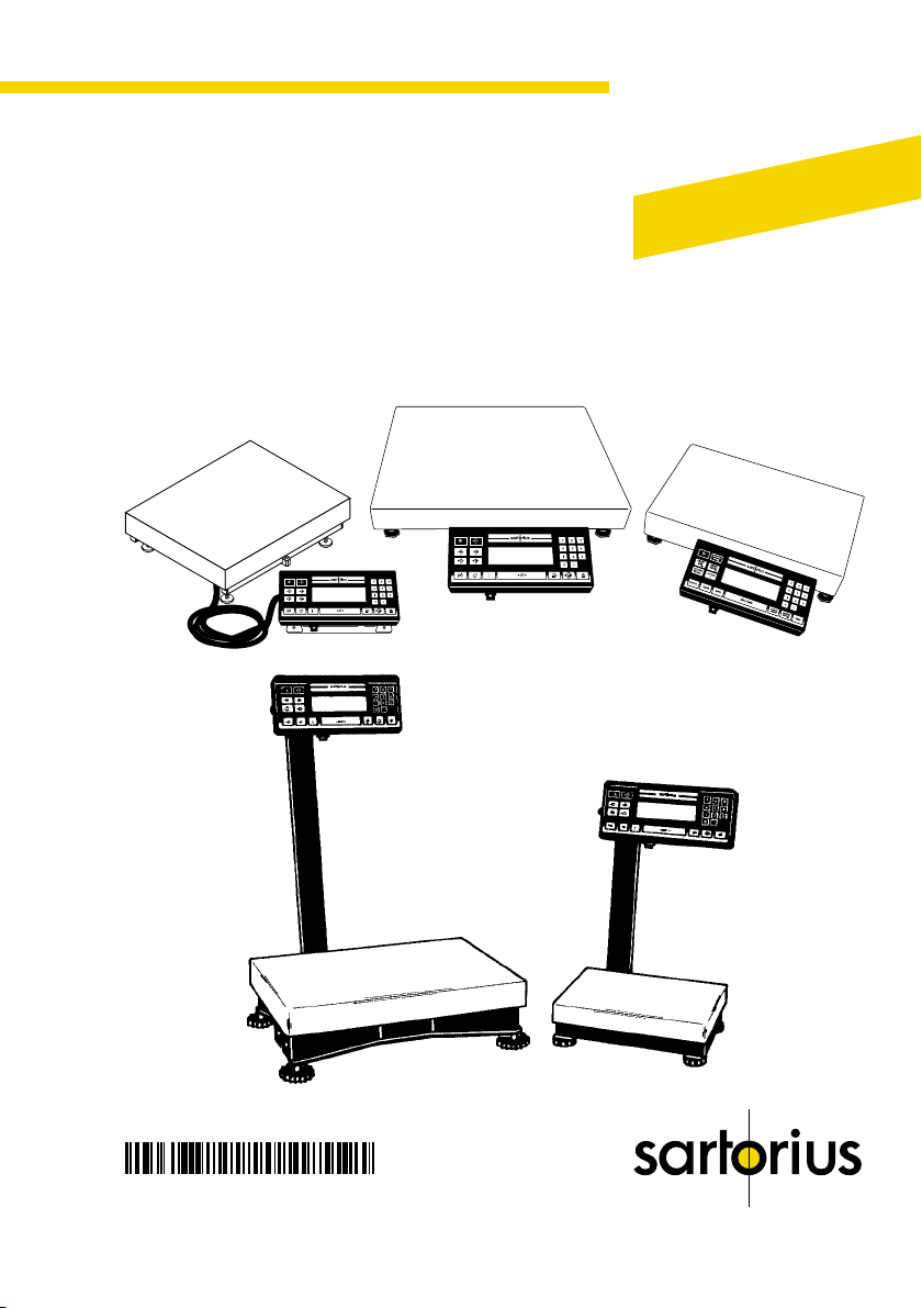
Sartorius QC Models
Electronic Scale
Operating Instructions for Standard QC Models and
QC Models Verifiable for Use in Legal Metrology
Industrial
Weighing Technology

Contents
Page
General View of the Scale 1– 0
Installation Instructions 1– 5
Zone 2/Class I, Division 2
Hazardous Areas/Locations 1– 8
Setting Up the Scale
– QC7 Models 1–10
– QC34 and QC64 Models 1–12
Mounting Options for the
Display Unit 1–14
Getting Started
Transport Locking Device 1–22
Using the Scale in
Legal Metrology 1–23
Connecting the Scale to
AC Power 1–24
Safety Precautions 1–26
Connecting Electronic
Peripheral Devices 1–27
Leveling the Scale Using
the Level Indicator 1–28
Declaration of Conformity 1–29
CE Marking 1–30
EC Type-Approval Certificate 1–33
Operating the Scale 1–35
Simple Weighing 1–36
Calibration/Adjustment 1–37
Data Interface
Connecting Electronic
Peripheral Devices 1–39
Interfacing Devices
with the Scale 1–40
Page
Care and Maintenance 1–42
Cleaning 1–42
Safety Inspection 1–43
Scale Operating Menu 2– 1
Changing Menu Code Settings 2– 1
Accessing the Menu 2– 2
Undoing All Menu Code
Changes – Reset Function 2– 3
Scale Operating Parameters 2– 4
Adapting the Scale
to Ambient Conditions 2– 4
Standard Weighing and
Manual Filling 2– 4
Stability Range 2– 4
Stability Symbol Delay 2– 5
Tare Parameter 2– 5
Auto Zero Function 2– 5
Calibration/Adjustment
and Linearization Functions
Using the e/o Key 2– 6
Simple Counting 2– 6
Weight Units 2– 7
Interface Parameter Settings
Baud Rate 2– 8
Parity 2– 8
Number of Stop Bits 2– 8
Handshake Mode 2– 8
Troubleshooting Guide 1–41
0–0

0–1
Page
Utilities for Printouts
or Data Transfer
Data Output Parameter 2– 9
Auto Print 2– 9
Data Output at
Defined Intervals 2–10
Data ID Codes 2–11
Automatic Output of the
Tare Memory Data 2–11
Printout/Record Configuration 2–12
Data Record Output 2–13
Additional Functions:
Menu Access Function 2–16
Beep Tone (Acoustic Signal) 2–16
Blocking the Keys 2–16
Blocking the Number Keys 2–16
Universal Switch for
Remote Control 2–17
Power-On Mode 2–17
Display Backlighting 2–18
Automatic Shutoff
(Battery Saver) 2–18
Undoing All Menu Code
Changes – Reset Function 2–19
Application Programs 3– 1
General Description
of the Data Interface 4– 1
Basic Program 4–10
Synchronization and
Data Output Parameters 4–13
Interface Parameter Settings 4–16
Cabling Diagram 4–19
Page
Specifications 5– 1
Accessories (Options) 5– 9
Index 6– 1
Supplement:
Brief Instructions
Card for insertion under the
dust cover
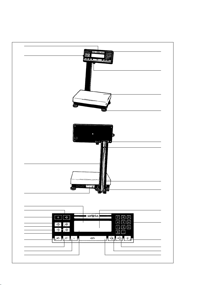
QC 7 Models
Note: This illustration shows only the -L0CE model with raised display
29
28
1
2
3
4
5
6
1–0
27
26
25
24
23
22
21
20
19
18
17
16
15
7
8
9
10
11
12
13
14

1–1
No. Designation
1 Display unit
2 Power socket
3 Load plate
4 Leveling foot
5 Retainers for the display unit
6 Clip
7 Fastening screws for the
support arm
8 Level indicator
9 Display
10 0 –9 and . number keys
11 p/p Print key (data output)
12 u/w Start key for
counting mode
13 g/W Key for toggling
between weighing/counting
applications, between reference
sample quantity and average
piece weight, or for toggling
weight units for all models
except QC34EDE-L0CE and
QC64EDE-L0CE
14 =/z Tare key – Zero/tare
No. Designation
15 Display for application programs
16 i/i Info key
17 c/c CF key
18 e/o On/Off
19 S/a Totalization memory –
add
20 s/r Data output – total
21 z/T Start checkweighing
mode
22 o/t Store value in tare
memory
23 d/d Store ID for individual
output values
24 r/s Memory (recall/store)
25 Bar graph (linear range indicator)
26 Manufacturer’s label
27 Support arm
28 Threaded cap on the interface port
29 ID label
(only for scales verified for use in
legal metrology)
Note: The keypad overlay shown here is the version for use in Europe.
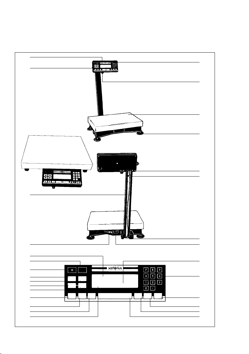
QC 34 and QC 64 Models
29
28
27
1
2
3
4
5
6
1–2
26
25
24
23
22
21
20
19
18
17
16
15
RECALL/
STORE
PRESET
PRESET
TARE
TARGET
ACCUM.
ACCUM.
RECALL
+
ON/OFF CLEAR INFO
COUNT/
WEIGHT
AV.PIECE
WEIGHT
7
8
9
10
PRINTZERO/TARE
11
12
13
14

1–3
No. Designation
1 Display unit
2 Power socket
3 Load plate
4 Leveling foot
5 Retainers for the display unit
6 Clip
7 Fastening screws for the
support arm
8 Level indicator
9 Display
10 0 –9 and . number keys
11 p/p Print key (data output)
12 u/w Start key for
counting mode
13 g/W Key for toggling
between weighing/counting
applications, between reference
sample quantity and average
piece weight, or for toggling
between weight units for all
models except QC34EDE-L0CE
and QC64EDE-L0CE
14 =/z Tare key – Zero/tare
No. Designation
15 Display for application programs
16 i/i Info key
17 c/c CF key
18 e/o On/off
19 S/a Totalization memory –
add
20 s/r Data output – total
21 z/T Start checkweighing
mode
22 o/t Store value in tare
memory
23 d/d Store ID for individual
output values
24 r/s Memory (recall/store)
25 Bar graph (linear range indicator)
26 Manufacturer’s label
27 Support arm
28 Threaded cap on the interface port
29 ID label
(only for scales verified for use in
legal metrology)
Note: The keypad overlay shown here is the version for use with -0UR models
in the US.

!
Important Note to Users
Make sure to carefully read and follow sections
marked with this symbol – they contain important
safety instructions.
If you turn off the scale while it is running on power
supplied by the battery pack and the external AC
adapter YRB06Z is not plugged in for recharging,
make sure to turn off the battery pack as well.
Note:
(For QC 34 and QC 64 models only)
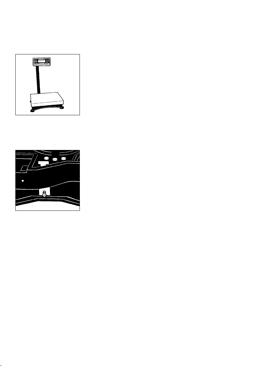
Transport Locking Device
Do not remove the transport locking device until the
scale is set up at the place of installation. Remove the
load plate.
The transport locking devices (yellow) are located on
the short sides of the scale.
Remove the transport locking devices (unfasten
them using an Allen wrench) before initially operating
the scale.
1–4
Verification Mark (Seal)
The law requires that a verified scale be sealed
with a verification mark. The verification marks
(seals) on a verified QC scale indicate that this scale
may only be opened and serviced by authorized
technicians, to ensure reliable and trouble-free
operation and to avoid forfeiture of the warranty
coverage. If a verification mark (seal) is damaged,
please observe the national laws and regulations
in effect at the place of installation.

Installation Instructions
Please read these installation and operating
instructions carefully before you begin operating your
new scale.
Intended Use
The QC series counting scales are ideal for use in
production and in warehouse management. They are
designed primarily for counting parts of identical
weight and for the related applications: totalizing,
checkweighing, documentation, counting and
for storing data on articles weighed. You can connect
a PC (for remote operation of your scale or for
integration into a warehouse management system)
or any of a variety of accessory devices to the data
interface port of the scale (see the section entitled
“Accessories (Options)”).
If you are interested in using your Sartorius QC scale
for any other purpose, please contact your Sartorius
Service Center. Sartorius does not accept any liability
connected with the use of their scales for other than
their intended purposes.
Warranty
Do not miss out on the benefits of our full warranty.
Please complete the warranty registration card,
indicating the date of installation, and return the card
to your Sartorius office or dealer.
1–5

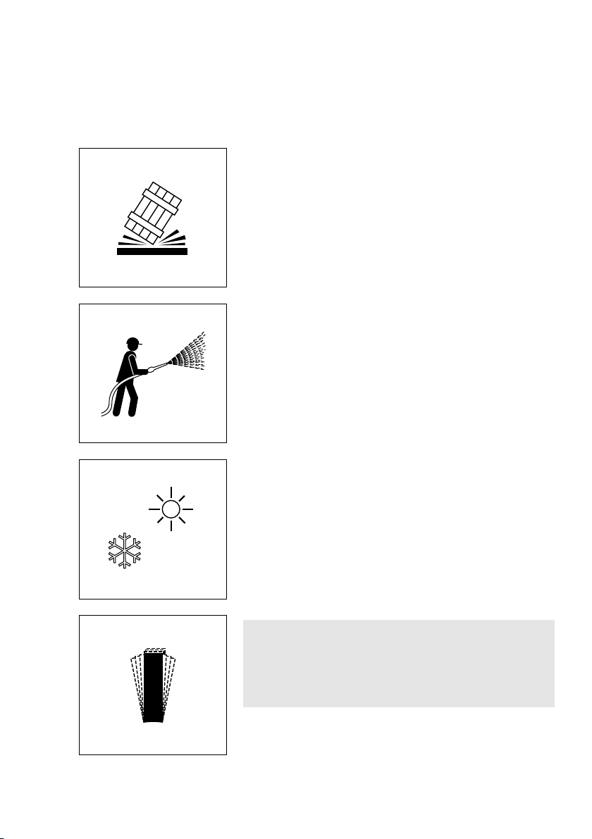
Storage and Shipping Conditions
Allowable storage temperature: –40°C...+70°C
–40°F...+158°F
The packaging has been designed to ensure that
the scale will not be damaged even if it is dropped
from a height of up to 80 cm (about 31inches).
After unpacking the scale, please check it immediately
for any visible damage as a result of rough handling
during shipment.
If this is the case, proceed as directed in the section
entitled “Safety Inspection.”
Save the box and all parts of the packaging for any
future shipment of your scale. Before packing your
scale, unplug all cables to prevent damage. Replace
the screw cap (28) on the data interface port.
To ensure your scale’s long service life:
Do not expose the scale unnecessarily to extreme
temperatures, moisture, blows, shocks or vibration.
Note:
This equipment has been tested and found to comply
with the limits for a Class A digital device, pursuant
to Part 15 of the FCC rules. These limits are designed
to provide reasonable protection against harmful
interference when the equipment is operated in a
commercial environment. This equipment generates,
uses and can radiate radio frequency energy and,
if not installed and used in accordance with the
instruction manual, may cause harmful interference
to radio communications. Operation of this
equipment in a residential area is likely to cause
harmful interference in which case the user will be
required to correct the interference at his own
expense. Changes or modifications not expressly
approved by Sartorius AG could void the user’s
authority to operate the equipment.
1–6
Installation
Ambient Conditions
Sartorius QC scales are designed to provide reliable
weighing and counting results under normal ambient
conditions encountered in industrial environments.
When choosing a location to set up your scale,
observe the following so that you will be able to work
with added speed and accuracy:
–
Set up the scale on an even, stable surface (table or floor)
– Avoid extreme heat radiation from heaters
or direct sunlight
– Protect the scale from drafts that come through open
doors and windows
– Avoid areas that may subject the scale to extreme
vibrations during weighing
– Protect the scale from aggressive chemical vapors
The scale may not be used in hazardous
areas/locations where there is danger of explosion.
Do not expose the scale to extreme moisture over long
periods of time. Moisture in the air can condense on
the surfaces of a cold scale whenever it is brought to
a substantially warmer place. If you transfer the scale to
a warmer area, make sure to condition it for about 2 hours
at room temperature, leaving it unplugged from AC
power. Afterwards, if you keep the scale connected to
AC power, the constant positive difference in
temperature between the inside of the scale and the
outside will practically rule out moisture condensation.
Note for QC Models Verifiable for Use in Legal Metrology:
The scale can be adapted to your individual requirements through simple changes to code settings in the
scale operating menu. For more information, see the
section entitled “Scale Operating Menu.”
Preparing the Scale for Verification as a Legal
Measuring Instrument in the EU*:
After initially connecting the scale to the power
supply (or after a relatively long power outage),
allow the scale to warm up for at least 24 hours.
1–7
°C
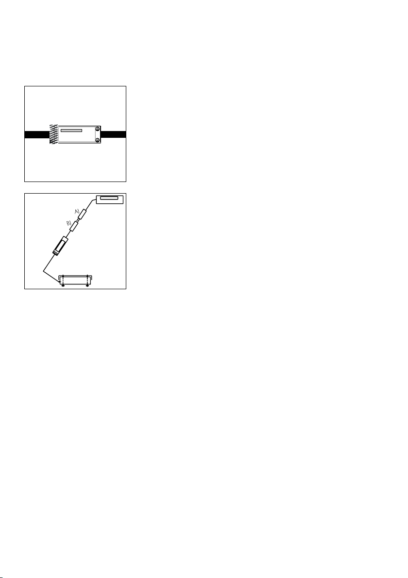
Check the serial number on the display unit of the QC
scale against the number on the tag ofthe scale cable.
Plug connector A into connector B.
Zone 2/Class I,Division 2 Hazardous Areas/Locations
You may operate the scale in a Zone 2 hazardous
area in Europe or in a Class I, Div. 2 hazardous
location (in the U.S. and Canada).
In this case, you must comply with the national electrical code and applicable safety regulations of your
country (in Germany, according to DIN VDE 0165).
For information on the legal regulations currently
applicable in your country, please ask your Sartorius
office or dealer.
To install the power supply, please read the instructions
in the section entitled “Getting Started.”
If you operate the scale in a Zone 2/Class I, Div. 2
hazardous area/location, you will need to observe
the installation conditions as described for the QC
display unit in the section entitled “Getting Started.”
The QC scale may not be operated in Zone 0,1, 20,
21 or22 hazardous areas/locations, as it does not
have an EX approval certificate for these areas.
1–8
* = including the Signatories of the Agreement on the
European Economic Area

Any tampering with the QC equipment by anyone,
other than authorized by Sartorius service
technicians, will result in forfeiture of all claims under
the manufacturer’s warranty!
Fastening an Antitheft Locking Device
QC 7 Model:
To protect the scale from theft, attach it in a secure
location using the lug located at the back of the scale.
QC 34 and QC 64 Models:
Thread a commercially available bicycle lock through
one of the fins in the lower housing of the scale.
The QC scale along with an ING2 power supply
is suitable for use in the following hazardous area
within the European Community:
Zone 2, Group II, temperature class T4 according to
EN 60079-14
In countries other than Germany, the QC scale
may not be used in a Zone 2/Class I, Div. 2
hazardous area/location unless approval for use
in such hazardous areas has been granted by
the local authorities.
Pursuant to the German Directive for the
Implementation of Regulations for Prevention of
Accidents “Elektrische Anlagen und Betriebsmittel”
(VBG 4) (Electrical Installations and Equipment) of
April,1986, and in conjunction with Article 10
of the Low Voltage Directive 72/23/EEC issued on
February 19,1973, by the European Community,
it is hereby certified that the equipment delivered,
the QC scale and accessories, has been
manufactured and tested in compliance with the
following DIN/VDE regulations:
DIN EN 60950
DIN EN 61010
1–9

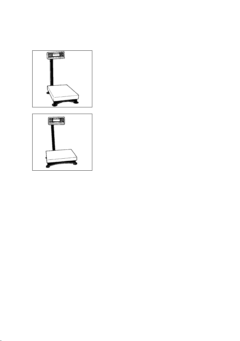
Setting Up the Scale
– QC 7 Models:
Carefully unpack the scale and accessories.
Mounting the Display Unit on a Table or Wall
(optional; order no. YDH01TS)
– Remove the retainers (5) from the support arm
– Remove the display unit
1–10
– Unfasten the screws on the display unit (7) and
remove the retainers.
– Slide the clips (6) which hold down the cable in
the raceway (channel) up and out of the support arm;
then remove the cable from the raceway.
– Remove the support arm.
– Then slide the clips back onto the support arm.
– Fasten the display unit holder to the display unit
using the retainers (5)
– Unfasten the retaining plate from the back
of the scale
– Unwind the cable as far as required and then
refasten the retaining plate
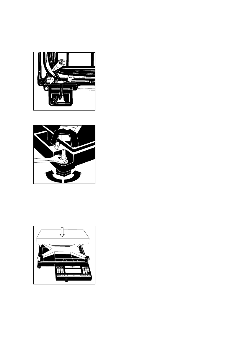
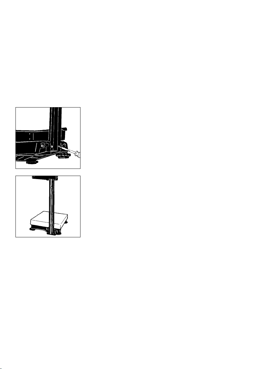
Leveling the Scale Using the Level Indicator
§ Level the scale using the level indicator as a guide.
$ Extend the leveling feet (turn clockwise)
to raise the scale
$ Retract the levelling feet (turn counterclockwise) to
lower the scale.
§ When the air bubble is exactly centered, use the
open-end wrench (spanner) to tighten the locknuts.
Important Note:
If you install the scale on a cart or trolley, it is sufficient
to level the scale once. Scales used as legal measuring
instruments are not allowed to be installed on a cart
or trolley!
§ Place the load plate on the scale base
1–11
– QC 34 and QC 64 Models:
Carefully unpack the scale and accessories.
Place the scale on a table and lay the support arm
and display unit next to it.
! Always secure the transport locking devices before
any transport of your scale. Unplug the scale
from AC power and remove the load plate from the
scale before changing the display mounting.
1–12
Mounting Options for the Display Unit
Note:
The following display mounting options apply
to QC 34 and QC 64 models only.
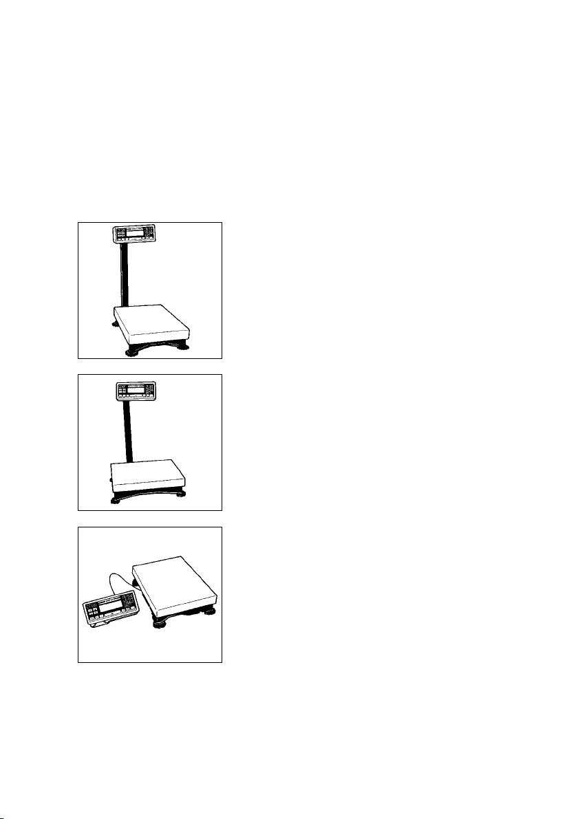
The display unit can be mounted as follows:
– on the short side of the scale (see page 1–14)
– on the back (long side) of the scale (see page 1–16)
– as a remote display unit (see page1–19 ); only
possible with the display holder which is available
as an option.
1–13
Mounting the Raised Display Unit on the Short Side
of the Scale
First, decide whether you want to mount the display on
the short side or on the back (long side) of the scale.
! Please follow the instructions given on page1–12
before you begin to change the display mounting.
Fasten the support arm to the base.
Note:
Use the center row of threaded drill holes when
inserting the screws.
Slide the clips into position to keep the cable from
slipping out of the raceway (channel).
1–14
Scale with the display unit mounted on the short side.
Scale with the display unit mounted on the back
(long side).
Note:
The cable routing will have to be changed, depending
on the position of the display unit.
1–15
Mounting the Raised Display Unit on the Long Side
of the Scale
Please be careful that the scale does not fall over
when disassembling and mounting the parts as
described here and in the following steps. Follow the
instructions given on page1–12 before you begin
to change the display mounting.
Lay the scale on its side to disassemble and mount the
display unit.
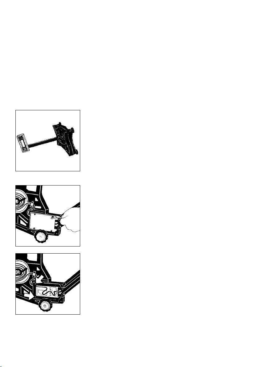
Unfasten the Allen screws on the base plate
and remove the base plate.
1–16
Remove the fastening screws.
Remove the screws on the retainer plate.
Then set the scale back upright.
Remove the screws on the base (7).
Lay the support arm along with the base and the
display unit on a table.
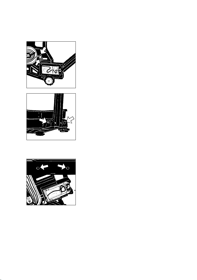
Remove the plugs from the long side of the scale
(insert them in the holes on the short side). Loosely
attach the display unit with the support arm and base
to the long side of the scale with the Allen screws.
Lay the scale on its side again.
Thread the cable through the raceway.
1–17
Refasten the retainer plate for the cable.
Refasten the frame with the fastening screws.
Refasten the base plate.
1–18
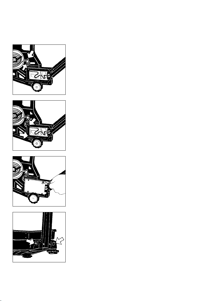
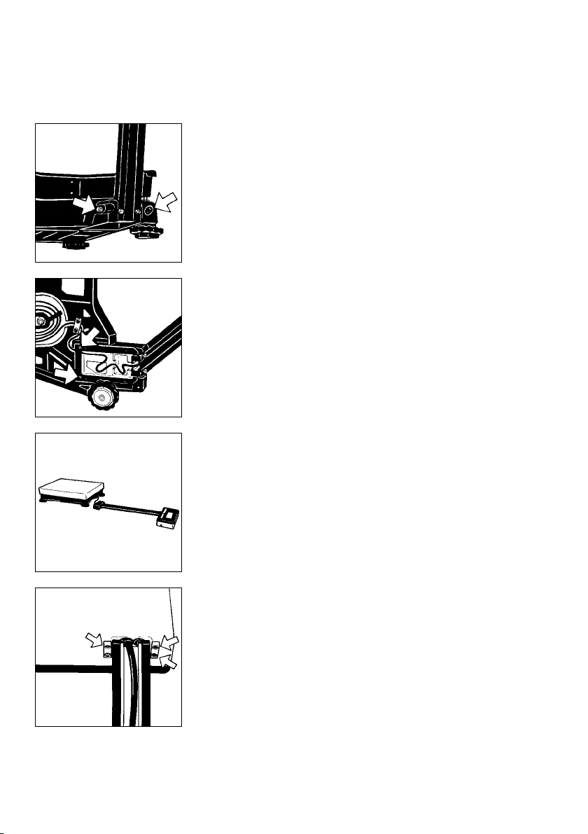
Set the scale back upright and tighten the Allen screws
on the base.
Follow these steps if you need to change the display
mounting again.
Mounting the Remote Display Unit (Option)
(only possible with the optional display holder;
order no. YDH01TS)
Note:
You can also mount the display as a remote unit
for the QC 7 model.
!
Please be careful that the scale does not fall over
when disassembling and mounting the parts as
described here and in the following steps. Follow the
instructions given on page1–12 before you begin to
change the display mounting.
Lay the scale on its side to disassemble and mount
the parts.
Unfasten the Allen screws on the base plate
and remove it.
Remove the screws on the retainer plate.
1–19
Remove the screws on the base (7) (see diagram
on the left).
Then set the scale back upright.
Remove the fastening screws.
Lay the support arm along with the base and the
display unit on a table.
1–20
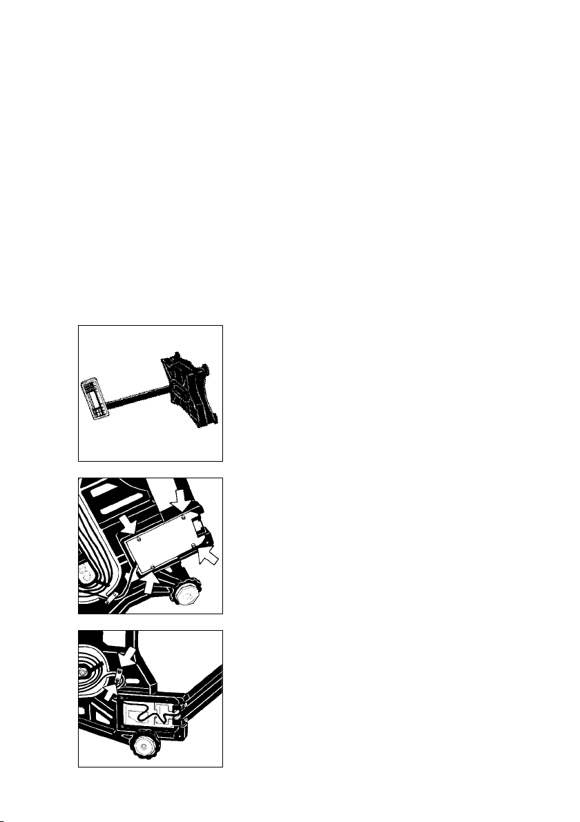
Unfasten the screws on the display unit (5) and remove
the retainers.
Slide the clips which hold down the cable in the
raceway up and out of the support arm.
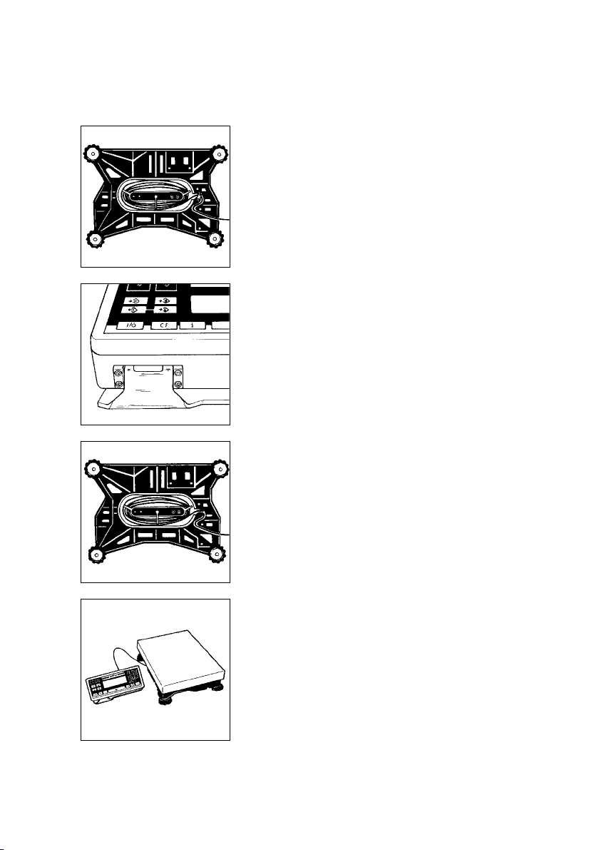
Unwind the cable as far as required.
Mount the display unit on the display holder using the
retainers you previously removed.
Now refasten the retainer plate for the cable.
Set the scale back upright.
1–21
Getting Started
Set the load plate (3) on the scale.
Note:
(For QC 34 and QC 64 models only)
Transport Locking Device
Set up the scale at the place of installation and remove
the load plate. The transport locking devices (yellow)
are located on the short sides of the scale.
Remove the transport locking devices (unfasten
them using an Allen wrench) before initially operating
the scale.
1–22
!
Verification Mark (Seal)
The law requires that a verified scale be sealed
with a verification mark. The verification marks (seals)
on a verified QC scale indicate that this scale
may only be opened and serviced by authorized
technicians, to ensure reliable and trouble-free
operation and to avoid forfeiture of the warranty
coverage. If a verification mark (seal) is damaged,
please observe the national laws and regulations
in effect at the place of installation.
Save the box and all parts of the packaging for any
future shipment of your scale.
Place the load plate on the scale.
Level the scale at the place of installation using the
leveling feet.

Using the Scale in Legal Metrology
(QC-...0CE Models)
* = Pursuant to Directive No. 90/384/EEC on non-automatic weighing instruments
Approved Auxiliary Measuring Devices
When using the load plate as a legal measuring instrument in the EU, you may
connect to it only auxiliary measuring devices that have been approved for
legal metrology. Metrologically relevant auxiliary devices, such as printers,
additional display units, etc., must be type-approved for this purpose and marked
by a green metrology sticker imprinted with a black “M.” The auxiliary device
must be verified in conjunction with the weighing instrument. If the auxiliary device
is connected at a later date to a weighing instrument that has already been used
in legal metrology, the responsible weights and measures office must be informed
of the addition of the auxiliary device. The auxiliary device can be used in legal
metrology, however, as soon as it has been properly connected if it has
the green metrology sticker with a black “M.”
Since the type-approval certificate for verification applies to non-automatic
weighing instruments only, you must comply with your country’s national
regulations that apply to the place of installation of your weighing instrument for
automatic operation with or without auxiliary devices installed.
To Be Filled Out by the Service Representative Authorized to Perform the
Initial Verification*:
Verified on (date):
The verification is valid for the following scale location:
Company/Name:
Serial no.:
Address:
City/Post code:
Country:
or Zone:
As a weighing instrument, the QC is not allowed to be used for weighing goods
intended for direct sale to the public, nor may it be used as a legal measuring
instrument until it has been initially verified by Sartorius. If the scale is moved, it
must be verified again at its new location. In this case, the scale must be
verified and stamp-approved at the new location by your local weights and
measures office.
1–23

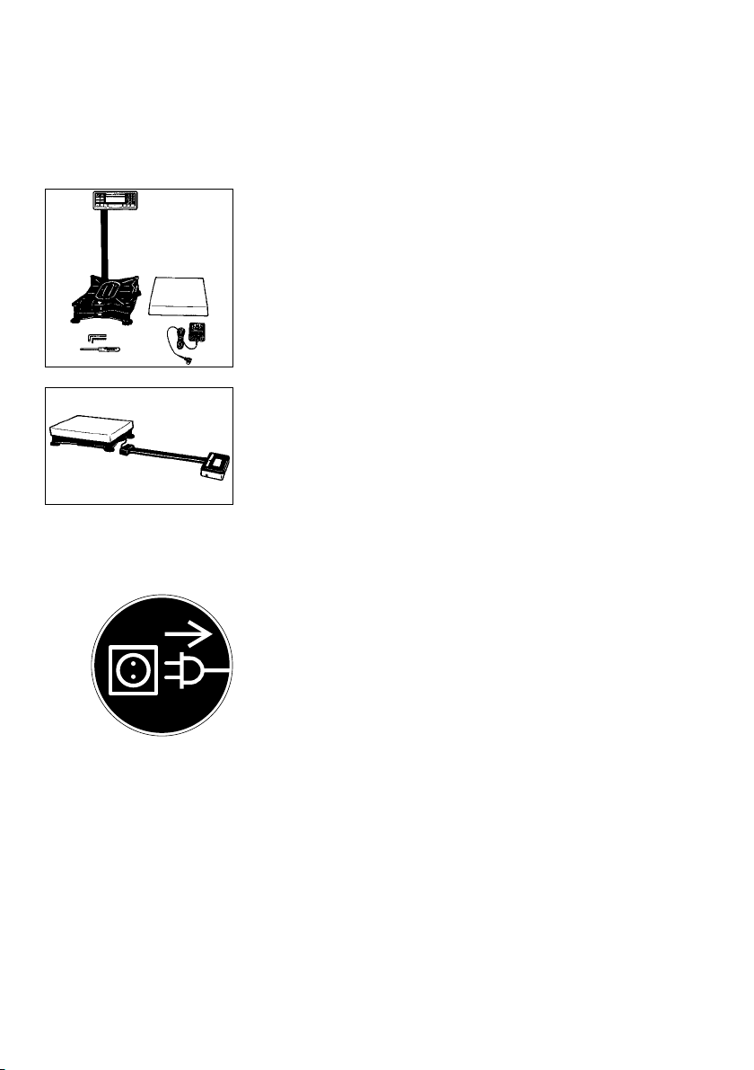
Connecting the Scale to AC Power
The scale is powered by an AC adapter supplied with the scale. Make sure that
the voltage rating printed on this unit is identical to that of your local line voltage.
If the voltage specified on the label or the plug design of the AC adapter do not
match the rating or standard you use, please contact your Sartorius office or dealer.
When you use the scale and associated equipment, you must comply with the
national electrical code and applicable safety regulations of your country.
If you use the QC scale in a Zone 2/Class I, Div. 2 hazardous area/location,
make sure to comply with the valid standards and regulations of your country,
applicable to the installation of equipment in a Zone 2/Class I, Div. 2 hazardous
area/location, e.g. in Germany with ElexV from 27.02.1980 (BGBI. I, P.214).
Only authorized technicians are allowed to install the equipment
in a Zone 2/Class I, Div. 2 hazardous area/location.
The female plug of the power cable must be securely fastened to the male socket
on the QC display unit. On the other end of the power cable,
– either an explosion-proof plug-and-socket connection must be installed
– or the plug must be detached from the power cable and the power cable
securely connected to a suitable junction box.
(Wiring Diagrams for Connecting the Scale
to the AC power in Zone 2/Class I, Div. 2 Hazardous Areas/Locations)
Brown (live (L))
Blue (neutral (N))
Yellow/green (grounding conductor)
Hook up the scale to the power supply in conformance with the installation
requirements of your country.
1–24

The IP 65-protected ING-2 no. 69 71899 AC adapter
is completely encapsulated and can be installed as a
stationary unit. To use a main feeder cable from the
ceiling or to mount a CEE plug, you will have to make
arrangements.
The IP 65 protection rating is ensured only if the square
rubber gasket is installed and the plug is connected
securely to form a hak-tight seal.
Ensure IP protection (Tighten the screw).
IP65 Protection (Painted Models) or IP67 Protection
(Stainless Steel FEP-I, IGP-I, FES-I and IGS-I Models)
The weighing platform is dusth-tight and washdownresistant in conformity with the IP65 or IP67 protection
rating, depending on the model.
Legend to Protection Ratings
First digit: rating 6 indicates resistance to penetration
by dust particles of a specified size. Second digit:
rating 5 indicates resistance to splashes of water,
as well as washdown-resistance. Rating 7 indicates
resistance to penetration by water during 30 minute
immersion up to a depth of 1meter (apporoximately
31/4feet).
IP65 or IP67 protections is only guaranteed if:
– the junction box seal was installed by a qualified
technician, and
– the connecting cables and cable glands were
installed and connected by a qualified technician.
1–25
 Loading...