

Sartorius QC64EDE-S, QC7CCE-D, QC7CCE-S0CE, QC34EDE-S0CE, QC64EDE-S0CE Operating Instructions Manual
...Page 1

This document courtesy of:
Data Weighing Systems, Inc.
Contact Us
For immediate assistance call
1-800-750-6842
Page 2
98648-009-86
Sartorius QC Models
Electronic Scale
Operating Instructions for Standard QC Models and
QC Models Verifiable for Use in Legal Metrology
Industrial
Weighing Technology
Page 3

Contents
Page
General View of the Scale 1– 0
Installation Instructions 1– 5
Zone 2/Class I, Division 2
Hazardous Areas/Locations 1– 8
Setting Up the Scale
– QC7 Models 1–10
– QC34 and QC64 Models 1–12
Mounting Options for the
Display Unit 1–14
Getting Started
Transport Locking Device 1–22
Using the Scale in
Legal Metrology 1–23
Connecting the Scale to
AC Power 1–24
Safety Precautions 1–26
Connecting Electronic
Peripheral Devices 1–27
Leveling the Scale Using
the Level Indicator 1–28
Declaration of Conformity 1–29
CE Marking 1–30
EC Type-Approval Certificate 1–33
Operating the Scale 1–35
Simple Weighing 1–36
Calibration/Adjustment 1–37
Data Interface
Connecting Electronic
Peripheral Devices 1–39
Interfacing Devices
with the Scale 1–40
Page
Care and Maintenance 1–42
Cleaning 1–42
Safety Inspection 1–43
Scale Operating Menu 2– 1
Changing Menu Code Settings 2– 1
Accessing the Menu 2– 2
Undoing All Menu Code
Changes – Reset Function 2– 3
Scale Operating Parameters 2– 4
Adapting the Scale
to Ambient Conditions 2– 4
Standard Weighing and
Manual Filling 2– 4
Stability Range 2– 4
Stability Symbol Delay 2– 5
Tare Parameter 2– 5
Auto Zero Function 2– 5
Calibration/Adjustment
and Linearization Functions
Using the e/o Key 2– 6
Simple Counting 2– 6
Weight Units 2– 7
Interface Parameter Settings
Baud Rate 2– 8
Parity 2– 8
Number of Stop Bits 2– 8
Handshake Mode 2– 8
Troubleshooting Guide 1–41
0–0
Page 4

0–1
Page
Utilities for Printouts
or Data Transfer
Data Output Parameter 2– 9
Auto Print 2– 9
Data Output at
Defined Intervals 2–10
Data ID Codes 2–11
Automatic Output of the
Tare Memory Data 2–11
Printout/Record Configuration 2–12
Data Record Output 2–13
Additional Functions:
Menu Access Function 2–16
Beep Tone (Acoustic Signal) 2–16
Blocking the Keys 2–16
Blocking the Number Keys 2–16
Universal Switch for
Remote Control 2–17
Power-On Mode 2–17
Display Backlighting 2–18
Automatic Shutoff
(Battery Saver) 2–18
Undoing All Menu Code
Changes – Reset Function 2–19
Application Programs 3– 1
General Description
of the Data Interface 4– 1
Basic Program 4–10
Synchronization and
Data Output Parameters 4–13
Interface Parameter Settings 4–16
Cabling Diagram 4–19
Page
Specifications 5– 1
Accessories (Options) 5– 9
Index 6– 1
Supplement:
Brief Instructions
Card for insertion under the
dust cover
Page 5
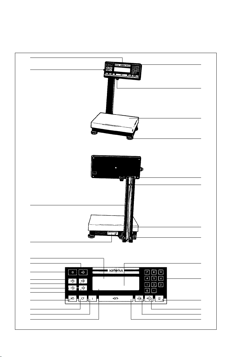
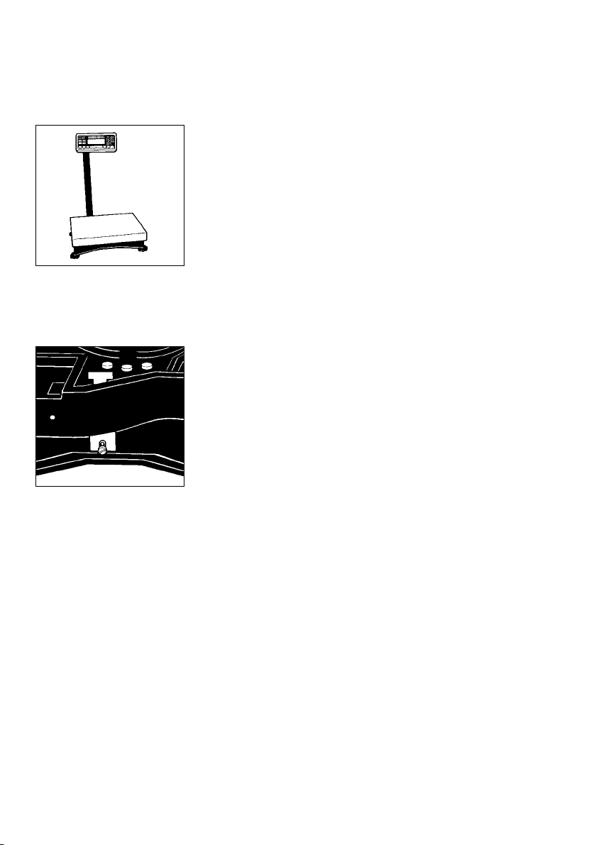
QC 7 Models
Note: This illustration shows only the -L0CE model with raised display
29
28
1
2
3
4
5
6
1–0
27
26
25
24
23
22
21
20
19
18
17
16
15
7
8
9
10
11
12
13
14
Page 6

1–1
No. Designation
1 Display unit
2 Power socket
3 Load plate
4 Leveling foot
5 Retainers for the display unit
6 Clip
7 Fastening screws for the
support arm
8 Level indicator
9 Display
10 0 –9 and . number keys
11 p/p Print key (data output)
12 u/w Start key for
counting mode
13 g/W Key for toggling
between weighing/counting
applications, between reference
sample quantity and average
piece weight, or for toggling
weight units for all models
except QC34EDE-L0CE and
QC64EDE-L0CE
14 =/z Tare key – Zero/tare
No. Designation
15 Display for application programs
16 i/i Info key
17 c/c CF key
18 e/o On/Off
19 S/a Totalization memory –
add
20 s/r Data output – total
21 z/T Start checkweighing
mode
22 o/t Store value in tare
memory
23 d/d Store ID for individual
output values
24 r/s Memory (recall/store)
25 Bar graph (linear range indicator)
26 Manufacturer’s label
27 Support arm
28 Threaded cap on the interface port
29 ID label
(only for scales verified for use in
legal metrology)
Note: The keypad overlay shown here is the version for use in Europe.
Page 7
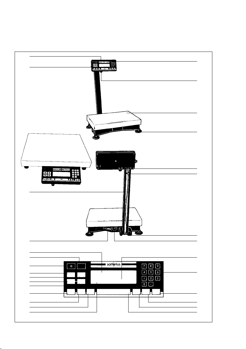
QC 34 and QC 64 Models
29
28
27
1
2
3
4
5
6
1–2
26
25
24
23
22
21
20
19
18
17
16
15
RECALL/
STORE
PRESET
PRESET
TARE
TARGET
ACCUM.
ACCUM.
RECALL
+
ON/OFF CLEAR INFO
COUNT/
WEIGHT
AV.PIECE
WEIGHT
7
8
9
10
PRINTZERO/TARE
11
12
13
14
Page 8

1–3
No. Designation
1 Display unit
2 Power socket
3 Load plate
4 Leveling foot
5 Retainers for the display unit
6 Clip
7 Fastening screws for the
support arm
8 Level indicator
9 Display
10 0 –9 and . number keys
11 p/p Print key (data output)
12 u/w Start key for
counting mode
13 g/W Key for toggling
between weighing/counting
applications, between reference
sample quantity and average
piece weight, or for toggling
between weight units for all
models except QC34EDE-L0CE
and QC64EDE-L0CE
14 =/z Tare key – Zero/tare
No. Designation
15 Display for application programs
16 i/i Info key
17 c/c CF key
18 e/o On/off
19 S/a Totalization memory –
add
20 s/r Data output – total
21 z/T Start checkweighing
mode
22 o/t Store value in tare
memory
23 d/d Store ID for individual
output values
24 r/s Memory (recall/store)
25 Bar graph (linear range indicator)
26 Manufacturer’s label
27 Support arm
28 Threaded cap on the interface port
29 ID label
(only for scales verified for use in
legal metrology)
Note: The keypad overlay shown here is the version for use with -0UR models
in the US.
Page 9

!
Important Note to Users
Make sure to carefully read and follow sections
marked with this symbol – they contain important
safety instructions.
If you turn off the scale while it is running on power
supplied by the battery pack and the external AC
adapter YRB06Z is not plugged in for recharging,
make sure to turn off the battery pack as well.
Note:
(For QC 34 and QC 64 models only)
Transport Locking Device
Do not remove the transport locking device until the
scale is set up at the place of installation. Remove the
load plate.
The transport locking devices (yellow) are located on
the short sides of the scale.
Remove the transport locking devices (unfasten
them using an Allen wrench) before initially operating
the scale.
1–4
Verification Mark (Seal)
The law requires that a verified scale be sealed
with a verification mark. The verification marks
(seals) on a verified QC scale indicate that this scale
may only be opened and serviced by authorized
technicians, to ensure reliable and trouble-free
operation and to avoid forfeiture of the warranty
coverage. If a verification mark (seal) is damaged,
please observe the national laws and regulations
in effect at the place of installation.
Page 10

Installation Instructions
Please read these installation and operating
instructions carefully before you begin operating your
new scale.
Intended Use
The QC series counting scales are ideal for use in
production and in warehouse management. They are
designed primarily for counting parts of identical
weight and for the related applications: totalizing,
checkweighing, documentation, counting and
for storing data on articles weighed. You can connect
a PC (for remote operation of your scale or for
integration into a warehouse management system)
or any of a variety of accessory devices to the data
interface port of the scale (see the section entitled
“Accessories (Options)”).
If you are interested in using your Sartorius QC scale
for any other purpose, please contact your Sartorius
Service Center. Sartorius does not accept any liability
connected with the use of their scales for other than
their intended purposes.
Warranty
Do not miss out on the benefits of our full warranty.
Please complete the warranty registration card,
indicating the date of installation, and return the card
to your Sartorius office or dealer.
1–5
Page 11

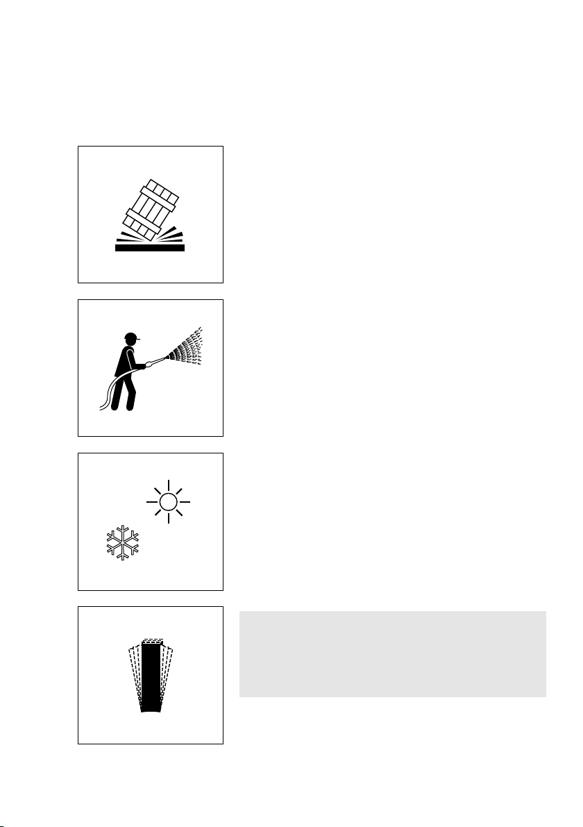
Storage and Shipping Conditions
Allowable storage temperature: –40°C...+70°C
–40°F...+158°F
The packaging has been designed to ensure that
the scale will not be damaged even if it is dropped
from a height of up to 80 cm (about 31inches).
After unpacking the scale, please check it immediately
for any visible damage as a result of rough handling
during shipment.
If this is the case, proceed as directed in the section
entitled “Safety Inspection.”
Save the box and all parts of the packaging for any
future shipment of your scale. Before packing your
scale, unplug all cables to prevent damage. Replace
the screw cap (28) on the data interface port.
To ensure your scale’s long service life:
Do not expose the scale unnecessarily to extreme
temperatures, moisture, blows, shocks or vibration.
Note:
This equipment has been tested and found to comply
with the limits for a Class A digital device, pursuant
to Part 15 of the FCC rules. These limits are designed
to provide reasonable protection against harmful
interference when the equipment is operated in a
commercial environment. This equipment generates,
uses and can radiate radio frequency energy and,
if not installed and used in accordance with the
instruction manual, may cause harmful interference
to radio communications. Operation of this
equipment in a residential area is likely to cause
harmful interference in which case the user will be
required to correct the interference at his own
expense. Changes or modifications not expressly
approved by Sartorius AG could void the user’s
authority to operate the equipment.
1–6
Page 12
Installation
Ambient Conditions
Sartorius QC scales are designed to provide reliable
weighing and counting results under normal ambient
conditions encountered in industrial environments.
When choosing a location to set up your scale,
observe the following so that you will be able to work
with added speed and accuracy:
–
Set up the scale on an even, stable surface (table or floor)
– Avoid extreme heat radiation from heaters
or direct sunlight
– Protect the scale from drafts that come through open
doors and windows
– Avoid areas that may subject the scale to extreme
vibrations during weighing
– Protect the scale from aggressive chemical vapors
The scale may not be used in hazardous
areas/locations where there is danger of explosion.
Do not expose the scale to extreme moisture over long
periods of time. Moisture in the air can condense on
the surfaces of a cold scale whenever it is brought to
a substantially warmer place. If you transfer the scale to
a warmer area, make sure to condition it for about 2 hours
at room temperature, leaving it unplugged from AC
power. Afterwards, if you keep the scale connected to
AC power, the constant positive difference in
temperature between the inside of the scale and the
outside will practically rule out moisture condensation.
Note for QC Models Verifiable for Use in Legal Metrology:
The scale can be adapted to your individual requirements through simple changes to code settings in the
scale operating menu. For more information, see the
section entitled “Scale Operating Menu.”
Preparing the Scale for Verification as a Legal
Measuring Instrument in the EU*:
After initially connecting the scale to the power
supply (or after a relatively long power outage),
allow the scale to warm up for at least 24 hours.
1–7
°C
Page 13
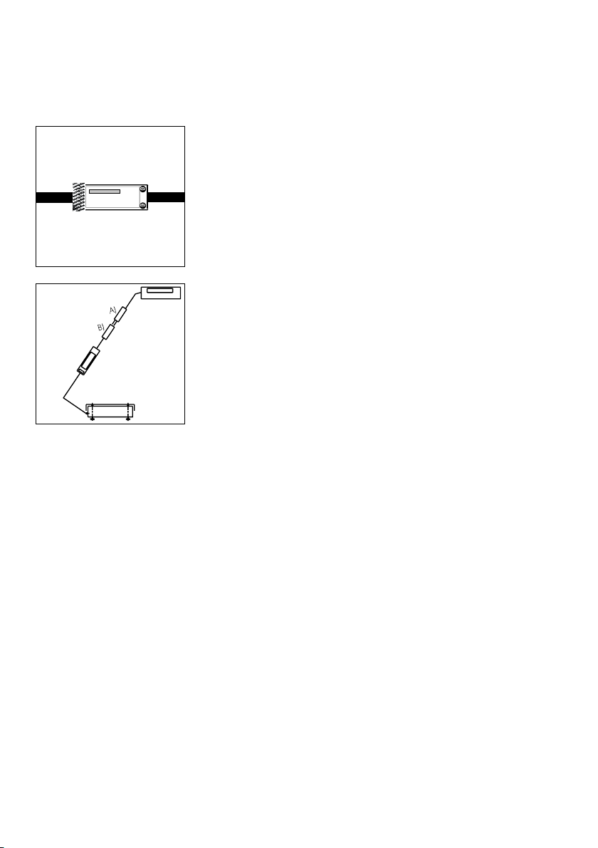
Check the serial number on the display unit of the QC
scale against the number on the tag ofthe scale cable.
Plug connector A into connector B.
Zone 2/Class I,Division 2 Hazardous Areas/Locations
You may operate the scale in a Zone 2 hazardous
area in Europe or in a Class I, Div. 2 hazardous
location (in the U.S. and Canada).
In this case, you must comply with the national electrical code and applicable safety regulations of your
country (in Germany, according to DIN VDE 0165).
For information on the legal regulations currently
applicable in your country, please ask your Sartorius
office or dealer.
To install the power supply, please read the instructions
in the section entitled “Getting Started.”
If you operate the scale in a Zone 2/Class I, Div. 2
hazardous area/location, you will need to observe
the installation conditions as described for the QC
display unit in the section entitled “Getting Started.”
The QC scale may not be operated in Zone 0,1, 20,
21 or22 hazardous areas/locations, as it does not
have an EX approval certificate for these areas.
1–8
* = including the Signatories of the Agreement on the
European Economic Area
Page 14

Any tampering with the QC equipment by anyone,
other than authorized by Sartorius service
technicians, will result in forfeiture of all claims under
the manufacturer’s warranty!
Fastening an Antitheft Locking Device
QC 7 Model:
To protect the scale from theft, attach it in a secure
location using the lug located at the back of the scale.
QC 34 and QC 64 Models:
Thread a commercially available bicycle lock through
one of the fins in the lower housing of the scale.
The QC scale along with an ING2 power supply
is suitable for use in the following hazardous area
within the European Community:
Zone 2, Group II, temperature class T4 according to
EN 60079-14
In countries other than Germany, the QC scale
may not be used in a Zone 2/Class I, Div. 2
hazardous area/location unless approval for use
in such hazardous areas has been granted by
the local authorities.
Pursuant to the German Directive for the
Implementation of Regulations for Prevention of
Accidents “Elektrische Anlagen und Betriebsmittel”
(VBG 4) (Electrical Installations and Equipment) of
April,1986, and in conjunction with Article 10
of the Low Voltage Directive 72/23/EEC issued on
February 19,1973, by the European Community,
it is hereby certified that the equipment delivered,
the QC scale and accessories, has been
manufactured and tested in compliance with the
following DIN/VDE regulations:
DIN EN 60950
DIN EN 61010
1–9
Page 15

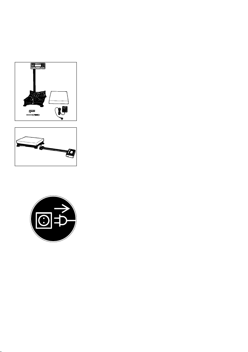
Setting Up the Scale
– QC 7 Models:
Carefully unpack the scale and accessories.
Mounting the Display Unit on a Table or Wall
(optional; order no. YDH01TS)
– Remove the retainers (5) from the support arm
– Remove the display unit
1–10
– Unfasten the screws on the display unit (7) and
remove the retainers.
– Slide the clips (6) which hold down the cable in
the raceway (channel) up and out of the support arm;
then remove the cable from the raceway.
– Remove the support arm.
– Then slide the clips back onto the support arm.
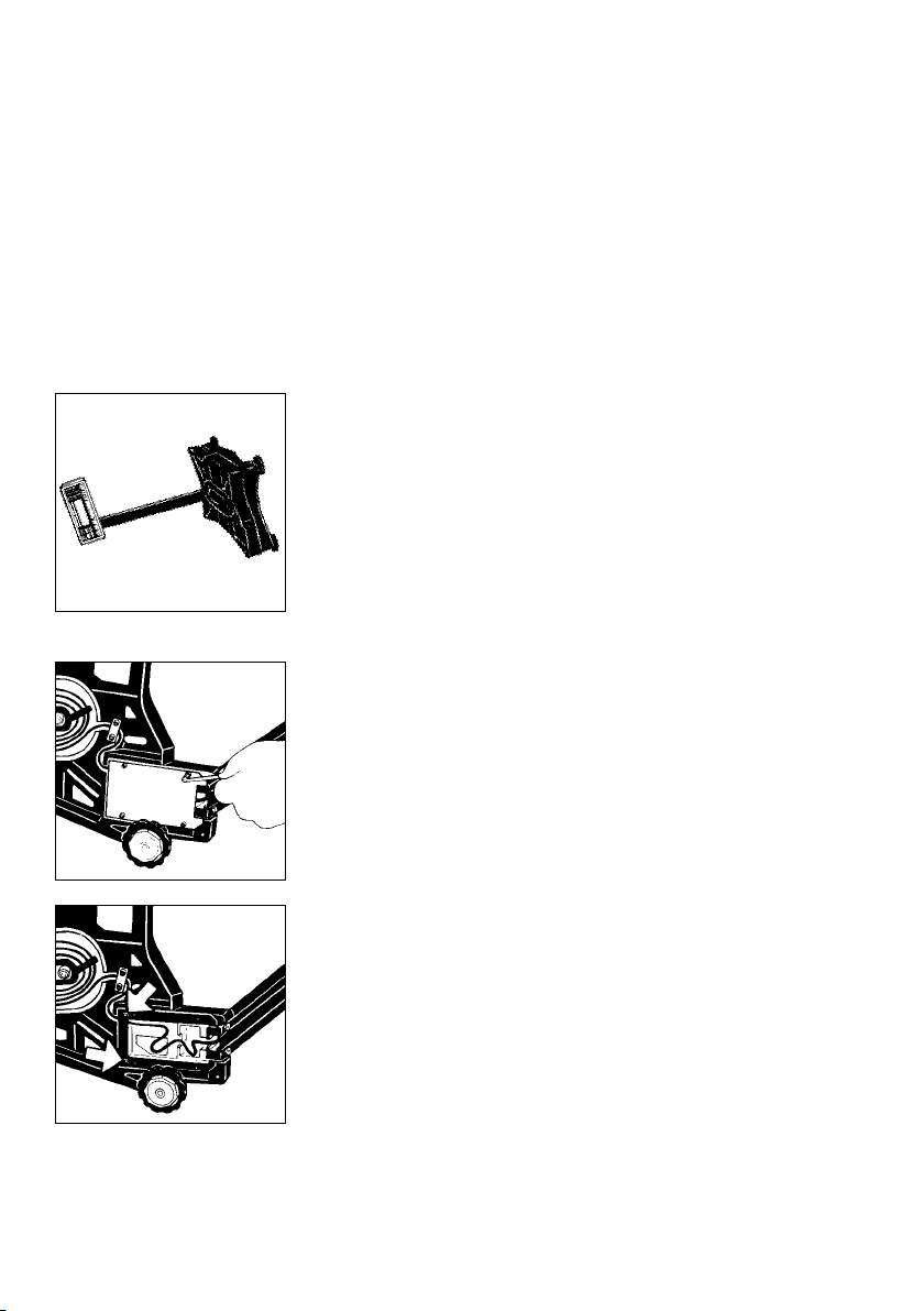
– Fasten the display unit holder to the display unit
using the retainers (5)
Page 16
– Unfasten the retaining plate from the back
of the scale
– Unwind the cable as far as required and then
refasten the retaining plate
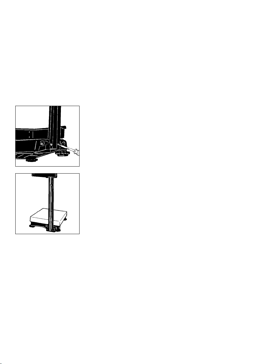
Leveling the Scale Using the Level Indicator
§ Level the scale using the level indicator as a guide.
$ Extend the leveling feet (turn clockwise)
to raise the scale
$ Retract the levelling feet (turn counterclockwise) to
lower the scale.
§ When the air bubble is exactly centered, use the
open-end wrench (spanner) to tighten the locknuts.
Important Note:
If you install the scale on a cart or trolley, it is sufficient
to level the scale once. Scales used as legal measuring
instruments are not allowed to be installed on a cart
or trolley!
§ Place the load plate on the scale base
1–11
Page 17
– QC 34 and QC 64 Models:
Carefully unpack the scale and accessories.
Place the scale on a table and lay the support arm
and display unit next to it.
! Always secure the transport locking devices before
any transport of your scale. Unplug the scale
from AC power and remove the load plate from the
scale before changing the display mounting.
1–12
Page 18
Mounting Options for the Display Unit
Note:
The following display mounting options apply
to QC 34 and QC 64 models only.
The display unit can be mounted as follows:
– on the short side of the scale (see page 1–14)
– on the back (long side) of the scale (see page 1–16)
– as a remote display unit (see page1–19 ); only
possible with the display holder which is available
as an option.
1–13
Page 19
Mounting the Raised Display Unit on the Short Side
of the Scale
First, decide whether you want to mount the display on
the short side or on the back (long side) of the scale.
! Please follow the instructions given on page1–12
before you begin to change the display mounting.
Fasten the support arm to the base.
Note:
Use the center row of threaded drill holes when
inserting the screws.
Slide the clips into position to keep the cable from
slipping out of the raceway (channel).
1–14
Page 20
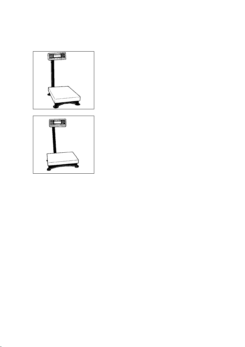
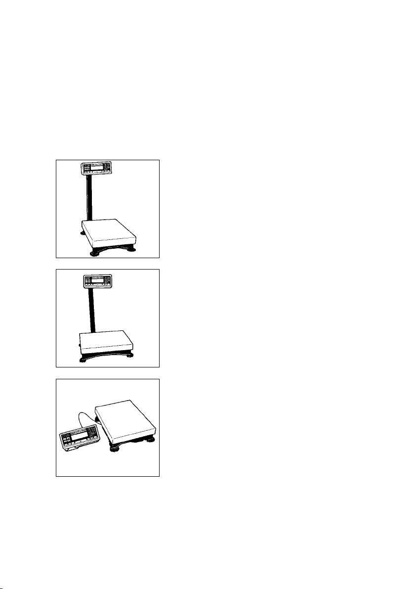
Scale with the display unit mounted on the short side.
Scale with the display unit mounted on the back
(long side).
Note:
The cable routing will have to be changed, depending
on the position of the display unit.
1–15
Page 21
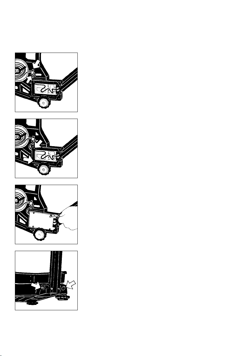
Mounting the Raised Display Unit on the Long Side
of the Scale
Please be careful that the scale does not fall over
when disassembling and mounting the parts as
described here and in the following steps. Follow the
instructions given on page1–12 before you begin
to change the display mounting.
Lay the scale on its side to disassemble and mount the
display unit.
Unfasten the Allen screws on the base plate
and remove the base plate.
1–16
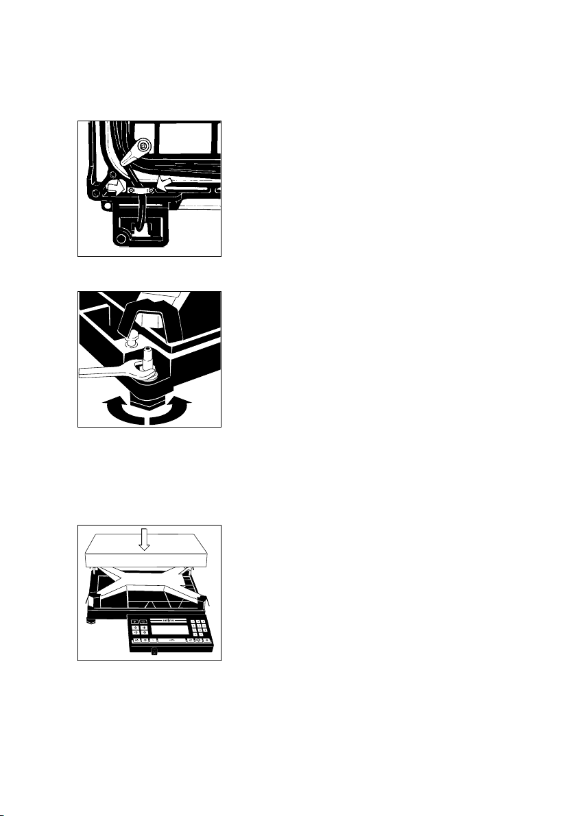
Remove the fastening screws.
Page 22
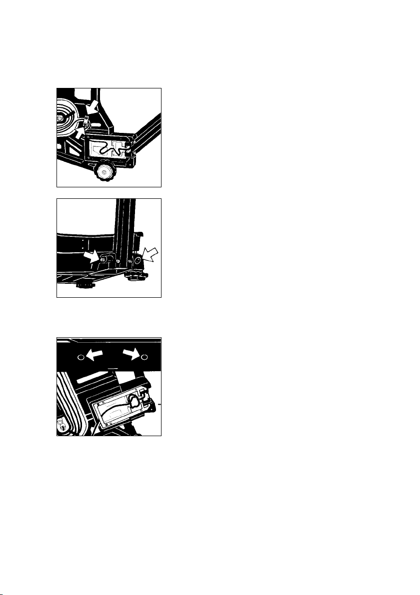
Remove the screws on the retainer plate.
Then set the scale back upright.
Remove the screws on the base (7).
Lay the support arm along with the base and the
display unit on a table.
Remove the plugs from the long side of the scale
(insert them in the holes on the short side). Loosely
attach the display unit with the support arm and base
to the long side of the scale with the Allen screws.
Lay the scale on its side again.
Thread the cable through the raceway.
1–17
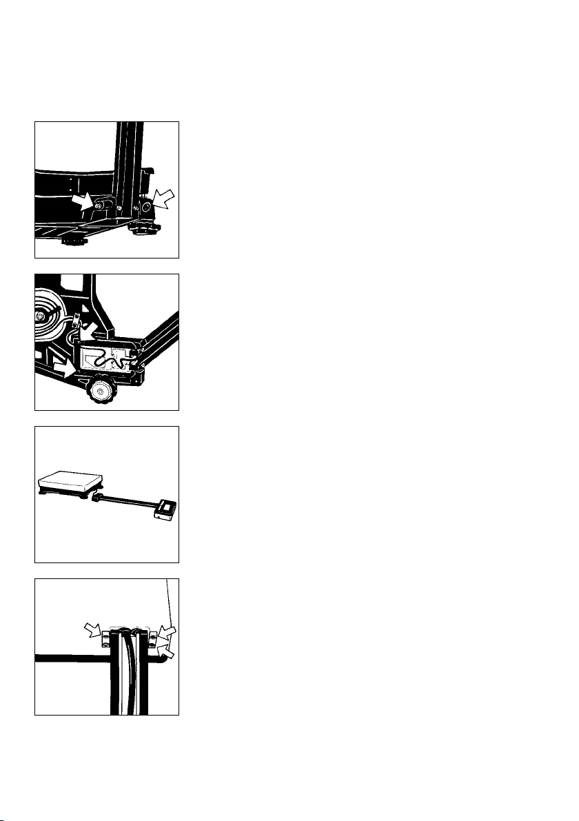
Page 23
Refasten the retainer plate for the cable.
Refasten the frame with the fastening screws.
Refasten the base plate.
1–18
Set the scale back upright and tighten the Allen screws
on the base.
Follow these steps if you need to change the display
mounting again.
Page 24
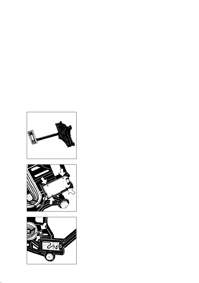
Mounting the Remote Display Unit (Option)
(only possible with the optional display holder;
order no. YDH01TS)
Note:
You can also mount the display as a remote unit
for the QC 7 model.
!
Please be careful that the scale does not fall over
when disassembling and mounting the parts as
described here and in the following steps. Follow the
instructions given on page1–12 before you begin to
change the display mounting.
Lay the scale on its side to disassemble and mount
the parts.
Unfasten the Allen screws on the base plate
and remove it.
Remove the screws on the retainer plate.
1–19
Page 25
Remove the screws on the base (7) (see diagram
on the left).
Then set the scale back upright.
Remove the fastening screws.
Lay the support arm along with the base and the
display unit on a table.
1–20
Unfasten the screws on the display unit (5) and remove
the retainers.
Slide the clips which hold down the cable in the
raceway up and out of the support arm.
Page 26
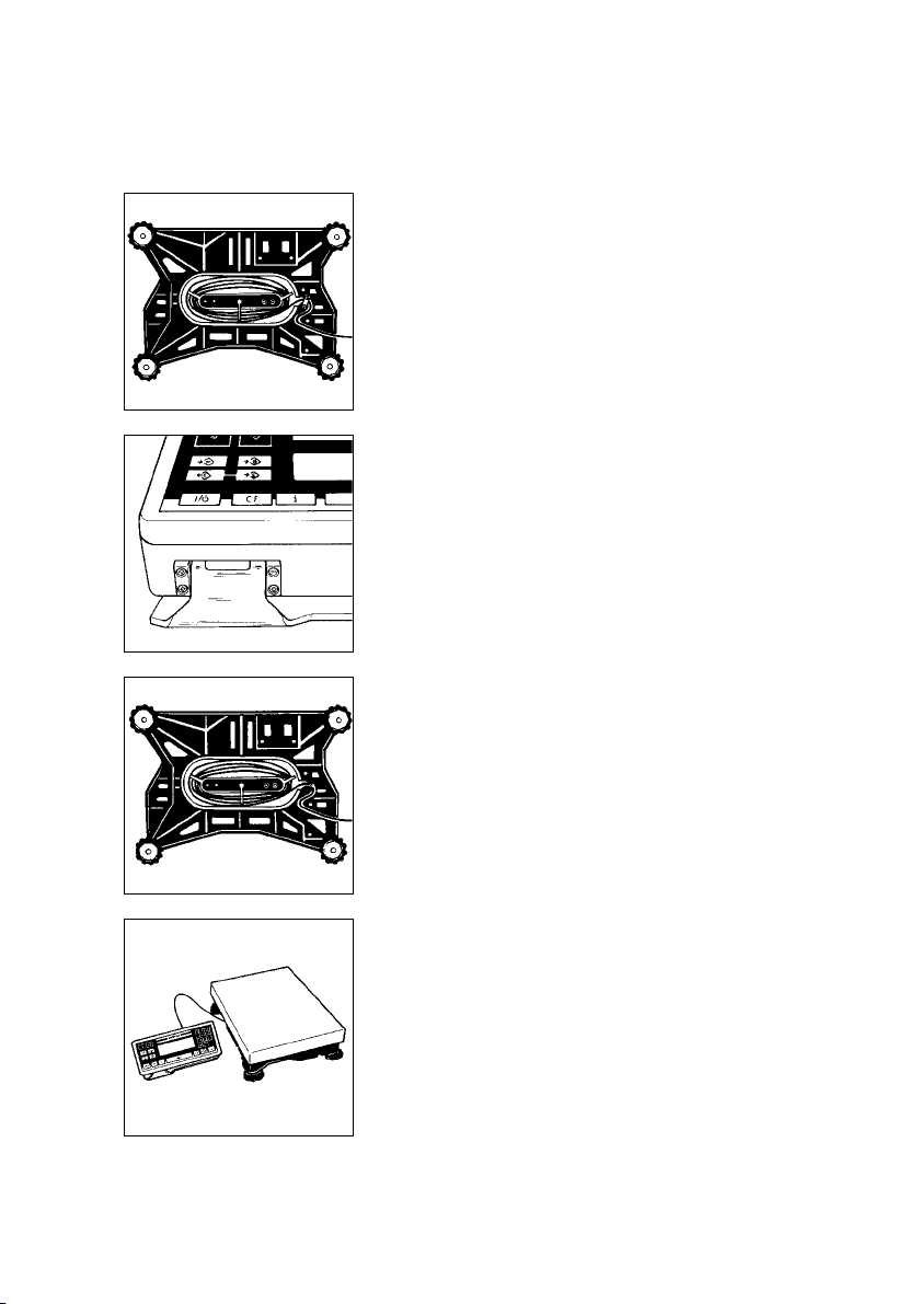
Unwind the cable as far as required.
Mount the display unit on the display holder using the
retainers you previously removed.
Now refasten the retainer plate for the cable.
Set the scale back upright.
1–21
Page 27
Getting Started
Set the load plate (3) on the scale.
Note:
(For QC 34 and QC 64 models only)
Transport Locking Device
Set up the scale at the place of installation and remove
the load plate. The transport locking devices (yellow)
are located on the short sides of the scale.
Remove the transport locking devices (unfasten
them using an Allen wrench) before initially operating
the scale.
1–22
!
Verification Mark (Seal)
The law requires that a verified scale be sealed
with a verification mark. The verification marks (seals)
on a verified QC scale indicate that this scale
may only be opened and serviced by authorized
technicians, to ensure reliable and trouble-free
operation and to avoid forfeiture of the warranty
coverage. If a verification mark (seal) is damaged,
please observe the national laws and regulations
in effect at the place of installation.
Save the box and all parts of the packaging for any
future shipment of your scale.
Place the load plate on the scale.
Level the scale at the place of installation using the
leveling feet.
Page 28

Using the Scale in Legal Metrology
(QC-...0CE Models)
* = Pursuant to Directive No. 90/384/EEC on non-automatic weighing instruments
Approved Auxiliary Measuring Devices
When using the load plate as a legal measuring instrument in the EU, you may
connect to it only auxiliary measuring devices that have been approved for
legal metrology. Metrologically relevant auxiliary devices, such as printers,
additional display units, etc., must be type-approved for this purpose and marked
by a green metrology sticker imprinted with a black “M.” The auxiliary device
must be verified in conjunction with the weighing instrument. If the auxiliary device
is connected at a later date to a weighing instrument that has already been used
in legal metrology, the responsible weights and measures office must be informed
of the addition of the auxiliary device. The auxiliary device can be used in legal
metrology, however, as soon as it has been properly connected if it has
the green metrology sticker with a black “M.”
Since the type-approval certificate for verification applies to non-automatic
weighing instruments only, you must comply with your country’s national
regulations that apply to the place of installation of your weighing instrument for
automatic operation with or without auxiliary devices installed.
To Be Filled Out by the Service Representative Authorized to Perform the
Initial Verification*:
Verified on (date):
The verification is valid for the following scale location:
Company/Name:
Serial no.:
Address:
City/Post code:
Country:
or Zone:
As a weighing instrument, the QC is not allowed to be used for weighing goods
intended for direct sale to the public, nor may it be used as a legal measuring
instrument until it has been initially verified by Sartorius. If the scale is moved, it
must be verified again at its new location. In this case, the scale must be
verified and stamp-approved at the new location by your local weights and
measures office.
1–23
Page 29

Connecting the Scale to AC Power
The scale is powered by an AC adapter supplied with the scale. Make sure that
the voltage rating printed on this unit is identical to that of your local line voltage.
If the voltage specified on the label or the plug design of the AC adapter do not
match the rating or standard you use, please contact your Sartorius office or dealer.
When you use the scale and associated equipment, you must comply with the
national electrical code and applicable safety regulations of your country.
If you use the QC scale in a Zone 2/Class I, Div. 2 hazardous area/location,
make sure to comply with the valid standards and regulations of your country,
applicable to the installation of equipment in a Zone 2/Class I, Div. 2 hazardous
area/location, e.g. in Germany with ElexV from 27.02.1980 (BGBI. I, P.214).
Only authorized technicians are allowed to install the equipment
in a Zone 2/Class I, Div. 2 hazardous area/location.
The female plug of the power cable must be securely fastened to the male socket
on the QC display unit. On the other end of the power cable,
– either an explosion-proof plug-and-socket connection must be installed
– or the plug must be detached from the power cable and the power cable
securely connected to a suitable junction box.
(Wiring Diagrams for Connecting the Scale
to the AC power in Zone 2/Class I, Div. 2 Hazardous Areas/Locations)
Brown (live (L))
Blue (neutral (N))
Yellow/green (grounding conductor)
Hook up the scale to the power supply in conformance with the installation
requirements of your country.
1–24
Page 30

The IP 65-protected ING-2 no. 69 71899 AC adapter
is completely encapsulated and can be installed as a
stationary unit. To use a main feeder cable from the
ceiling or to mount a CEE plug, you will have to make
arrangements.
The IP 65 protection rating is ensured only if the square
rubber gasket is installed and the plug is connected
securely to form a hak-tight seal.
Ensure IP protection (Tighten the screw).
IP65 Protection (Painted Models) or IP67 Protection
(Stainless Steel FEP-I, IGP-I, FES-I and IGS-I Models)
The weighing platform is dusth-tight and washdownresistant in conformity with the IP65 or IP67 protection
rating, depending on the model.
Legend to Protection Ratings
First digit: rating 6 indicates resistance to penetration
by dust particles of a specified size. Second digit:
rating 5 indicates resistance to splashes of water,
as well as washdown-resistance. Rating 7 indicates
resistance to penetration by water during 30 minute
immersion up to a depth of 1meter (apporoximately
31/4feet).
IP65 or IP67 protections is only guaranteed if:
– the junction box seal was installed by a qualified
technician, and
– the connecting cables and cable glands were
installed and connected by a qualified technician.
1–25
Page 31

!
Use only original Sartorius AC adapters. Use of AC
adapters from other manufacturers, even if these units
have a registered approval rating from a national
testing laboratory, requires the approval of an
authorized Sartorius service technician.
To operate the scale using an external rechargeable
battery pack, see the section entitled “Accessories
(Options)”.
First insert the right-angle plug into the jack on the scale
as shown (2) and tighten the screw.
The IP 65 protection rating is ensured only if the square
rubber gasket is installed and the plug
is connected securely to form a leak-tight seal.
Installation within Safe Areas:
Plug the AC adapter into a wall outlet (mains).
Note:
Thread the AC adapter cable through the channel
(raceway) on the support arm (27).
Slide the clips (6) into position to keep the cable from
slipping out of the raceway.
1–26
Safety Precautions
The AC adapter, rated to Class 2 (double insulation)
can be plugged into any wall outlet without taking any
additional safety precautions. The pole of the output
voltage is connected to the scale housing, which can
be grounded for operation.
The interface is also electrically connected to the
scale housing (ground) (see also “Data Interface” on
page1–39).
Page 32

Connecting Electronic Peripheral Devices
Make absolutely sure to unplug the scale from the
power supply before you connect or disconnect
a peripheral device (e.g. printer, PC, etc.) to or from
the interface port.
Adjusting the Display Unit
Adjust the display unit to the position desired.
If you use the QC scale in a Zone 2/Class I, Div. 2
hazardous area/location, the QC equipment must
be completely disconnected from AC power before
you connect or disconnect any cables to or from
the equipment. The same applies to all accessories
operated with the system.
1–27
Page 33

Leveling the Scale Using the Level Indicator
At the place of installation, level the scale using the
leveling feet (4) as follows, so that the air bubble is
centered within the circle of the level indicator (8).
Then check to make sure that all four feet are resting
on the surface of the benchtop (stability test).
Extend leveling feet (turn clockwise) to raise the scale.
Retract leveling feet (turn counterclockwise) to lower
the scale.
Note:
When installing the scale on a transportable cart,
a single setting is sufficient.
Equipment used as a legal weighing instrument is not
allowed to be installed on a ramp.
Installing a Drive-on Ramp
(For the models FEP-I, IGP-I, FES-I und IGS-I)
The drive-on ramp must be installed and put into
operation by a trained Sartorius dealer or service
technician.
See the table in the “Accessories” list to order the
drive-on ramp suited for use with your weighing
platform.
1–28
Page 34

Declaration of Conformity
CE Marking of Sartorius Devices
In 1985, the Council of the European Community approved a resolution
concerninga new approach to the technical harmonization and standardization
of national regulations. The organization for monitoring compliance with the
directives and standards concerning C marking is governed in the individual
EU Member States through the implementation of the EC Directives adopted
by the respective national laws.
Sartorius complies with the EC Directives and European Standards in order to
supply its customers with weighing instruments that feature the latest advanced
technology and provide many years of trouble-free service.
The C mark may be affixed only to weighing instruments and associated
equipment that comply with the applicable Directive(s):
Council Directive 89/336/EEC “Electromagnetic Compatibility (EMC)«
This Directive regulates the use of equipment that can cause electromagnetic
interference or whose functioning can be influenced by such interference:
The safety requirements are
– limitation of emissions
– defined immunity to interference
The Declaration of Conformity is included in this manual.
For further information concerning C marking on Sartorius equipment,
please request the corresponding brochure available under publication no.
WYD6056-p98023.
Important Note:
Additional instruction manual(s) that belong to these Operating Instructions:
Guide to Verification of Weighing Instruments with the YCO01IS-0CE or
YCO02IS-0CE.
Please carefully read, complete and file this Guide
1–29
Page 35

C Marking
The C marking affixed to the equipment indicates that the equipment meets the
requirements of the following Directive(s):
Council Directive 89/336/EEC “Electromagnetic compatibility (EMC)”
This Directive regulates the use of equipment that can cause electromagnetic
interference or whose functioning can be influenced by such interference.
Applicable European Standards:
Limitation EN 50081-1 Residential, commercial and
of emissions light industry
EN 50081-2 Industrial environment
Defined immunity EN 50082-1 Residential, commercial and
to interference light industry
EN 50082-2 Industrial environment
Important Note:
The operator shall be responsible for any modifications to Sartorius equipment
and for any connections of cables or equipment not supplied by Sartorius and must
check and, if necessary, correct these modifications and connections.
On request, Sartorius will provide information on the minimum operating
specifications (in accordance with the Standards listed above for defined immunity
to interference).
Council Directive 73/23/EEC
“Electrical equipment designed for use within certain voltage limits”
Applicable European Standards:
EN 60950 Safety of information technology equipment including
electrical business equipment
EN 61010 Safety requirements for electrical equipment for measurement,
control and laboratory use
Part 1: General requirements
If you use electrical equipment in installations and under ambient conditions
requiring higher safety standards, you must comply with the provisions as specified
in the applicable regulations for installation in your country.
1–30
Page 36

Weighing Instruments for Use in Legal Metrology:
Council Directive 90/384/EEC
“Non-Automatic Weighing Instruments”
This Directive regulates/the determination of mass in
legal metrology.
For the respective Declaration of Conformity for
weighing instruments that have been verified by
SARTORIUS for use as legal measuring instruments
and that have an EC Type-Approval Certificate,
see the next page.
This Directive also regulates the performance of the
EC verification by the manufacturer, provided that an
EC Type-Approval Certificate has been issued and
the manufacturer has been accredited by an officer of
a Notified Body registered at the Commission of the
European Community for performing such verification.
The legal basis allowing Sartorius to perform EC
verification is constituted by the EC Council Directive
No. 90/384/EEC on non-automatic weighing
instruments that has been in effect since January 1,
1993, in the Internal Market as well as by the
Certificate of Accreditation of the Sartorius AG
Quality Management System issued by the Metrology
Department of the Regional Administration Office of
Lower Saxony, Germany (“Niedersächsisches
Landesverwaltungsamt – Eichwesen”) on February
15, 1993.
For information on the C mark on Sartorius
equipment and legal regulations currently applicable
in your country, and to obtain the names of the
persons to contact, please ask your local Sartorius
office, dealer or service center.
1–31
Page 37

Declaration of Type Conformity
1–32
Page 38

1–33
EC Type-Approval Certificate
Page 39

“EC Verification” –
a Service Offered by Sartorius
Our service technicians authorized to perform the
verification* of your weighing instruments that
are acceptable for legal metrological verification can
inspect and verify the metrological specifications
at the place of installation within the Member States
of the European Union and the Signatories of the
European Economic Area.
“New Installation” Service
Initial verification is covered in our “New Installation”
service package. In addition to initial verification, this
package provides you with a series of important
services which will guarantee you optimal results in
working with your weighing instrument:
− Installation
− Startup
− Inspection
− Training
− Initial verification
Subsequent Verifications within the
European Countries
1–34
The validity of the verification will become void in
accordance with the national regulations of the
country in which the weighing instrument is used. For
information on verification and legal regulations
currently applicable in your country, and to obtain the
names of persons to contact, please ask your local
Sartorius office, dealer or service center.
* in accordance with the accreditation certificate
issued to Sartorius AG
Page 40

Operating the Scale
Turning the Scale On and Off
Press the e/o key (18) to turn the display on
and off.
Self-Test
When the scale is switched on, an automatic self-test
of the scale’s electronic circuitry is performed.
At the end of the self-test, a zero readout is displayed.
This means that the scale is ready for use.
If an error is found during the self-test, the display
reads: “Err xx”.
Note:
If the “Err xx” error code is displayed, see the
“Troubleshooting Guide” in this manual.
For verified scales QC 7CCE-S0CE and
QC 64EDE-S0CE, which have a verification scale
interval “e” that is greater than the scale interval “d,”
the last digit on the display is bordered.
The display shows the following special codes
for your information:
OFF*
displayed in the upper right corner indicates that the
scale was disconnected from AC power (scale
reconnected to AC power or power outage longer
than 3 seconds).
O* displayed in the lower left corner means Stand-by
The display has been turned off by pressing e/o
(18), or the scale shut itself off automatically (see Scale
Operating Menu). The scale is now in the ready-tooperate mode and does not need to warm up.
* depends on the “Power-On Mode” setting in the
scale operating menu
O
OFF
1–35
▼
Page 41

b
b means Busy
Once you turn on the scale, the b symbol is
displayed until you press a key. During operation, this
symbol indicates that the scale is still busy processing
a function and will not accept another command to
perform any other functions at this time.
Important Note Concerning Scales Verifiable for Use
as Legal Measuring Instruments:
A weight readout can be displayed in grams “g”
or kilograms “kg” (depends on model).
In addition to grams and kilograms, you can also
weigh in other international weight units on all
standard scales. See the “Scale Operating Menu”
in Part 2 of this manual.
For verified scales QC 7CCE-S0CE and
QC 64EDE-S0CE, which have a verification scale
interval “e” that is greater than the scale interval “d”,
the last digit on the display is bordered.
Taring
A weight can be determined with accuracy only from
a defined zero point. Press the =/z key (14) to
zero the weight display. You can tare within the
▼
entire weighing range of the scale.
1–36
Simple Weighing
Place your sample on the load plate (3) to determine
the weight. Read off the weight indicated on the
display only after the weight unit “g” or “kg” appears
as the stability symbol.
Page 42

Calibration/Adjustment
“Calibration” technically means to determine the
difference between the scale readout and the actual
weight on the platform to determine the accuracy.
Adjustment means to bring a scale to the level
of accuracy required for its use.
Note:
For 0CE-series scales, the calibration function is sealed
and locked after verification.
You must adjust or calibrate your new scale at the
place of installation after each warmup period and
before the first measurement. You must also re-adjust
or recalibrate your scale each time you set it up
in a different area or when the ambient conditions
change (especially the temperature).
Menu code: 1 9 1*
Use only calibration weights with an accuracy equal
to or better than the readability of your scale.
You can find an overview of the calibration weight
sets available in the section entitled “Accessories
(Options).” You need an exact calibration weight.
Type QC7CCE-S QC34EDE-S QC64EDE-S
Weight (g) 1x5,000 1x10,000 2 x10,000
Accuracy
class F1 F1 F1
* = factory setting
1–37
Page 43

When a zero readout is displayed, press the
=/z key (14). This starts calibration. The
▼
calibration weight is displayed in grams.
Errors or interference at the start of the calibration
routine are indicated by the error code “Err 02.”
If this is the case, tare and press the =/z key
again when a zero readout appears.
Center the calibration weight on the load plate.
The scale then calibrates automatically. At the end of
calibration, the calibration weight readout and the
stability symbol “g” or “kg” are displayed.
Blocking the Calibration Functions
You can block the calibration functions by setting
code 1 9 7.
1–38
Page 44

Data Interface
If you wish to record weighing data using a Sartorius
Data Printer, plug the YCC01-0016M3 data cable
into the interface port (28) of the scale. You do not
need to adjust any settings!
Connecting Electronic Peripheral Devices
Make absolutely sure to unplug the scale from AC
power before you connect or disconnect a peripheral
device (printer or PC) to or from the interface port.
The IP 65 protection rating is ensured only if
the square rubber gasket is installed and the plug is
connected securely to form a leakproof seal.
Unscrew the protective cap (28) that covers the data
interface port.
Note:
Keep the protective cap in a safe place where it will
not get lost!
– Plug the connector into the interface port
– Secure the connector with the screw ring
1–39
Page 45

Note:
If you use the QC scale in a Zone 2/Class I, Div. 2
hazardous area/location, the QC equipment
must be completely disconnected from AC power
before you connect or disconnect any cables
to or from the equipment. The same applies to all
accessories operated with the system.
Press the p/p key (11) to output data.
For information on data output parameters and data
ID codes, see the section entitled “Utilities for Printouts
or Data Transfer.” For details on the data interface
(such as the data output or input format, pin
assignment, etc.), see Part 4, “General Description of
the Data Interface.”
Interfacing Devices with the Scale
Please note that the interface port is electrically
connected to the protective grounding conductor of the
scale housing. The interface cables supplied as
standard equipment are shielded and both ends of
each cable are electrically connected to the connector
cases. This connection may result in interference
caused by ground loops or by transient currents if you
have grounded the housing or connected the
protective grounding conductor for line power.
If necessary, connect an equipotential bonding
conductor to the scale.
1–40
Page 46

Troubleshooting Guide
Problem Causes Solution
No segments – No AC power is available – Check the AC power
appear in the weight supply
display (1) – The AC adapter is not – Plug in the AC adapter
plugged in
The weight display – The load exceeds the – Unload the scale
shows “H” capacity of the scale
The weight display – The load plate (3) – Position the platform
shows “L” or “Err 54” is not in place
The weight display – The display did not show – Press the =/z
briefly shows “Err 02” a zero readout when the key (14); then press the
=/z key (14) =/z key again
was pressed to calibrate and hold it until
the calibration weight
is displayed
– The scale is loaded – Unload the scale
The special code “b” – None of the keys has – Press a key
remains displayed been pressed since the
scale was turned on
The weight readout – Unstable ambient conditions – Set up the scale
changes constantly in another area
– Too much vibration, or the – Access the menu to
scale is exposed to a draft select the correct code
for the weighing
environment (e.g.11 4)
The scale cannot – There is a foreign object – Remove the foreign
be stabilized between the load plate object
and the scale housing
The weight readout – The scale is not calibrated – Calibrate the scale
is obviously wrong (see page1–36)
– The scale was not tared – Tare before weighing
before weighing
– The air bubble of the – Level the scale
level indicator (8) is not (see page1–27)
within the circle
1–41
Page 47

Care and Maintenance
Service
Regular servicing by a Sartorius service technician
will extend the service life of your scale and
ensure its continued weighing accuracy. Sartorius can
offer you service contracts, with your choice of
regular maintenance intervals ranging from 1 month
to 2 years.
Cleaning
Before cleaning the scale, unplug the AC adapter
from the wall outlet.
Please do not use any aggressive cleaning agents
(solvents or similar agents). Instead, use a piece
of cloth which has been wet with a mild detergent
(soap). Make sure that no liquid enters the scale
housing. After cleaning, wipe the scale down with
a soft, dry piece of cloth.
1–42
Note:
If the water that you use to clean the scale is too hot or
cold, the difference in temperature between the water
and the scale can cause condensation within the
scale (according to EN 60529 on IP65 protection).
This condensation may cause the scale to malfunction!
Page 48

Safety Inspection
If there is any indication that safe operation of the
scale with the AC adapter is no longer warranted,
turn off the power and disconnect the equipment from
AC power immediately. Lock the equipment in
a secure place to ensure that it cannot be used for the
time being.
Safe operation is no longer ensured when
– there is visible damage to the AC adapter
– the AC adapter no longer functions properly
– the AC adapter has been stored for a relatively
long period under unfavorable conditions.
Instructions for Recycling the Packaging
To ensure safe shipment, your scale has been
packaged using environmentally friendly materials.
After successful installation of the equipment, you
should return this packaging for recycling.
For information on recycling old weighing equipment,
consult your communal or municipal waste disposal
center or local recycling depot.
1–43
Page 49

Scale Operating Menu
Changing Settings in the Scale Operating Menu
In the operating menu, you can define how your scale will adapt to ambient
conditions and also how it will work to meet your special requirements.
The factory settings of the scale operating menu are identified by an “*”. You can
select the functions not identified by an “*” by setting the respective menu codes.
You can find the codes in the section entitled “Scale Operating Parameters” which
starts on page 2 - 4. If you need to change any of the factory settings, we
recommend that you enter these changes along with the date in the column headed
by “Changes.”
The keys have special functions for setting
menu codes:
u/w (12) = Increases a number by one with
each press (the numbers change
in cycles)
=/z (14) = Confirms a code setting; stores a
code setting and exits the menu
p/p (11) = Moves to the next of the three
numbers of a code
(1st – 2nd –3rd – 1st – etc.)
Now try changing a code to adapt your scale
to a special power-on mode. The code for “Automatic
power-on” is 8 5 4.
Changing Menu Code Settings
To select specific functions, you will need to change
the respective menu code.
There are three steps to changing a code:
– Accessing the menu
– Setting the code
– Confirming and storing the code
2–1
Page 50

Accessing the Menu
– Press e/o (18) to turn off the scale.
Turn the scale back on.
– While all segments are displayed, briefly hold
down the =/z key (14).
C
▼
– Release when “1” (“–C–”) is displayed.
Note:
If you use the scale as a legal measuring instrument,
the “external calibration” function is blocked.
Only menu items that are permitted for scale
▼
operation in legal metrology can be read and
changed by the user!
– Press u/w (12) until “8” appears.
▼
– Press p/p until the 2nd number of the
code appears.
▼
▼
– Press u/w until “5” appears
– Press p/p until the 3rd number appears
(when you move to this number, the previously set
menu code will appear).
▼
▼
– Press u/w to select “4.”
– Confirming Code Changes
Press =/z (14 ) to confirm the code you have
just set (this is indicated by the “o” after the code).
Note:
▼
– To store the new menu code setting, press
=/z (14) for more than two seconds until the
self-test function starts.
2–2
Page 51

Important Note:
Changes to the code settings are not stored if you
turn off the scale by pressing e/o while selecting
the code numbers or before saving a setting.
The current menu setting in the scale operating menu
is identified by a small, superscript “o” after the last
number. When you access the operating menu,
the previously set code will be displayed after you
have selected the right-hand number, which means the
entire menu code setting is displayed. This makes it
easy for you to check the previously set codes.
If you want to change several menu code settings,
you do not have to press =/z (14) after each
change to exit the scale operating menu. You can
also confirm individual settings.
Undoing All Menu Code Changes – Reset Function
The reset function lets you undo all menu code
changes, which means you will obtain the original
factory-set menu codes identified here by an “*”.
To use this function, select code 9 – – 1°.
For information on confirming and storing menu code
settings see the previous page.
2–3
Page 52

Scale Operating Parameters
Adapting the Scale to Ambient Conditions
The scale can be adapted to the prevailing ambient conditions at the place
of installation.
Code Changes
Very stable conditions 1 1 1
Stable conditions 1 1 2 *
Unstable conditions 1 1 3
Very unstable conditions 1 1 4
Standard Weighing Mode – Manual Filling Mode
You can optimally adapt your scale to meet either of these requirements.
In the manual filling mode, the display compensates for fluctuations of the load
on the scale, giving you especially fast and stable readouts.
Code Changes
Standard weighing mode 1 2 1 *
Manual filling mode 1 2 2
(e.g. if you need to package screws in certain quantities)
Stability Range
The stability symbol will remain displayed in the case of a weight variation +/–.
Code Changes
0.25 digit 1 3 1
0.5 digit 1 3 2 ***
1 digit1) 133
2 digits1) 1 3 4 * (**)
4 digits2) 135
8 digits2) 136
* Settings for standard models
** Settings for QC 7CCE-S0CE and QC 64EDE-S0CE models
*** Settings for QC 7-,34-,64- L0CE and QC 34EDE-S0CE models
1
) blocked for all verifiable models of accuracy class m.
2
) blocked for all verifiable models
2–4
Page 53

Stability Symbol Delay
This setting allows your scale to compensate for individual interfering factors
which slowly subside. You will not need to make any changes in this code setting,
as a rule.
Code Changes
No delay 1 4 1
Short delay 1 4 2 *
Long delay 1 4 3
Extremely long delay 1 4 4
Tare Parameter
You can define when the scale will perform the taring operation.
Code Changes
At any time1)151
Not until the readout is stable 1 5 2 *
Auto-Zero Function
When this zero tracking function is activated, any changes off the zero readout
that are equal to a defined fraction of digits per second are automatically tared.
If the deviation is less than the defined fraction, the internal taring function of
the scale will be initiated (e.g. 0.5 digit per second). In other words, it ensures
a stable zero.
Code Changes
Auto-Zero on 1 6 1 *
Auto-Zero off 1 6 2
1
) blocked for all verifiable models
*= factory setting
2–5
Page 54

Calibration/Adjustment and Linearization Functions Using the =/z Key
(hold down key for more than 2 seconds)
Important Note:
For verifiable scales used as legal measuring instruments the menu access switch is
blocked and sealed. The external calibration is not permitted.
External Calibration and/or Linearization
The weights to be placed on the scale for linearization are indicated in the display
one after the other, in increasing order.
Calibration/adjustment and linearization Code Changes
External calibration 1 9 1 *
External linearization 1 9 5
Adjustment/calibration function blocked 1 9 7 **
* = factory setting
** = blocked for all veryfiable models
2–6
Page 55

Weight Units
Note:
For verified scales approved for use as legal measuring instruments all weight units
except g/kg are blocked.
Code*** Symbol Conversation factor Code Changes
1g =
User-definable unit *** 1. 1 7 1
Grams g 1. 1 7 2 *
Kilograms kg 0.001 1 7 3 **
Carats ct 5. 1 7 4
Pounds 14 /lb 0.0022046226 1 7 5
Ounces oz 0.035273962 1 7 6
Troy ounces ozt 0.032150747 1 7 7
Hong Kong taels 8 tlh 0.02671725 1 7 8
Singapore taels 9 tls 0.02646063 1 7 9
Taiwanese taels 10 tlt 0.02666666 1 7 10
Grains GN 15.43235835 1 7 11
Pennyweights dwt 0.643014931 1 7 12
Parts per pound o 1.1287667712 1 7 14
Chinese taels 15 tlc 0.02645547175 1 7 15
Mommes 16 m 0.2667 1 7 16
Austrian carats 17 k 5. 1 7 17
Tola 18 tol 0.0857333381 1 7 18
Baht 19 bat 0.06578947436 1 7 19
Mesghal 20 MS 0.217 1 7 20
* = factory setting
** = factory setting for QC 34/QC 64EDE scales and scales verifiable for use
as legal measuring instruments (QC 34EDE-L0CE and QC 64EDE-L0CE)
*** = some of the unit symbols printed on hard copy or output on a computer
screen will differ from the way they are shown on the scale display.
2–7
Page 56

Interface Parameter Settings
Baud Rate Code Changes
150 baud 5 1 1
300 baud 5 1 2
600 baud 5 1 3
1,200 baud 5 1 4 *
2,400 baud 5 1 5
4,800 baud 5 1 6
9,600 baud 5 1 7
19,200 baud 5 1 8
Parity Code Changes Mark 5 2 1 Space 5 2 2 Odd 5 2 3 * Even 5 2 4
Number of Stop Bits Code Changes 1 stop bit 5 3 1 * 2 stop bits 5 3 2
Handshake Mode Code Changes Software handshake 5 4 1 Hardware handshake with 2 characters after CTS 5 4 2 * Hardware handshake with 1 character after CTS 5 4 3
* = factory setting
2–8
Page 57

Utilities for Printouts or Data Transfer
Sartorius QC scales come standard with an interface.
You can plug a Sartorius printer or a computer into this interface port. In addition,
you can choose to have data output from your scale to this on-line device either
automatically or by pressing the p/p key.
The scale operating menu lets you define the various parameters for data output.
For information on the data formats and for interfacing a computer or a different
peripheral device, see Part 4, “General Description of the Data Interface.”
Data Output Parameter
This parameter is coupled with the stability parameter; stability = stable readout
or no motion is detected.
Print on request = data is output only when the p/p key is pressed
or a software command is received
Auto print = continuous, automatic data output
Code Changes
Print on request regardless of stability 6 1 1
Print on request after stability, with storage of the function 6 1 2 *
Print on request after stability, without storage of the function 6 1 3
Auto print regardless of stability 6 1 4
Auto print at stability 6 1 5
Auto Print
You can stop and start automatic data output (auto print function) by pressing
the p/p key (11). To avoid operating errors or to ensure that the data will be
output continuously in the automatic mode, you can block this function.
Start/stop auto print using the Code Changes
p/p key 6 2 1
Auto print not stoppable 6 2 2 *
* = factory setting
2–9
Page 58

Data Output at Defined Intervals
You can reduce the volume of data in the “auto print” mode by defining the
interval at which data will be output automatically. This auto print interval is based
on the number of display updates.
Auto print interval Code Changes
1 display update 6 3 1 *
2 display updates 6 3 2
5 display updates1) 633
10 display updates1) 634
20 display updates1) 635
50 display updates1) 636
100 display updates1) 637
Automatic Taring after Data Output
You can have the scale tare automatically (=/z key function) after one of the
following keys is pressed:
Code Changes
No function 6 4 1 *
Automatic taring after pressing the p/p key 6 4 2
Automatic taring after pressing the S/a key 6 4 6
Automatic Output of the Application Parameters
You can have the application parameters and results printed out or transferred to an
on-line computer (e.g. checkweighing limits, tare memory, etc.) automatically when
the application is activated.
Code Changes
Off 711*
On 712
1
) blocked for all verifiable models
* = factory setting
2–10
Page 59

Data ID Codes
To help you identify weights, piece counts, percentages, etc., a code letter is
printed or displayed in front of these values.
If you set the code for “without data ID code,” only net weights, results in percent
and counting results will be output. You will find the data ID codes for a particular
application program listed in the corresponding description. The ID code
increases the data output format for each weight readout from16 to 22 characters.
ID code for data output Code Changes
Without 7 2 1
With 7 2 2 *
Automatic Output of the Tare Memory Data
If you have assigned the o/t key (22) to the tare memory, the following
values will be output automatically:
Code Changes
Last net value (individual value N1) 7 3 1 *
Tare memory data (tare balancing memory) 7 3 2
This function only works in conjunction with the code setting 7 1 2 – “Automatic
Output of the Application Parameters.”
* = factory setting
2–11
Page 60

Printout/Record Configuration
The printout/record can be configured to meet your special requirements.
Depending on the menu code settings you select, you can have the weighing data
output from your scale to a Sartorius printer (e.g. the YDP 03-0CE) or to an on-line
computer. The data that is output also depends on the code settings.
The printout/record can have the following lines:
The ID code designates:
08-JAN-97 15:38:32 Current date and time, taken from the printer
(with YDP 03-0CE only)
Maier and Co. First header line – manufacturer/company
name, saved in non-volatile memory
(up to 20 characters)
Wiesbaden Second header line – enter data of your
choice, saved in non-volatile memory
(up to 20 characters)
ArtNo.12345678901234 Third header line – 6 characters –,
saved in non-volatile memory
Fourth header line – a field for entering
additional identification data
(up to14 characters)
nRef + 10 pcs Reference sample quantity (piece count)*
wRef +9.4880 g Reference weight*
n+22 Current components – only with “Totalizing”*
N1 +4744.0 g Current net value
T1 + 56.0 g Tare memory*
B +4800.0 g Current gross value*
Qnt + 500 pcs Current piece count*
Selectable line-feed (0 to 3 lines)
* These values are only output if you have selected the respective application
(only with YDP 03-0CE printer)
2–12
Page 61

Data Record Output
You can have the printout/record output automatically, or by pressing the
p/p key (as often as you like), depending on the menu code selected
(see following pages).
Output Date, Time and Number Entered
For additional documentation, you can enter up to14 characters (fourth header
line) through the number pad (keys 0–9), for example to record article, order,
customer or batch numbers. Information entered through the number pad (keys
0–9) is saved by pressing the ID key and automatically output with the
printout/record. These entries can be overwritten at any time.
You can assign a fixed identification (third header line) of up to 6 characters
to precede the14-character identifier described above. This ID can be entered
through an on-line computer, or by a Sartorius service technician. The on-line
computer can also receive data from the scale. By connecting a printer, you can
print the data received in the computer. These data are saved in non-volatile
memory. For more information, see the section entitled “Interface Description.”
You can choose between two printers:
Industrial printer YDP01IS-0CE
Data printer YDP03-0CE
2–13
Page 62

Data output with data and time
The data output ID is different for each printer.
“Data Printer” can output the article no. (ID) with the date and time.
The industrial printer only prints the article no. (ID).
You can vary the data on the printout by changing the respective menu settings:
Code YDP03-0CE Printer YDP01IS-0CE Printer
7 4 1 No output No output
7 4 2 Output date/time Form feed only
7 4 3 Output article no. (ID) Output article no. (ID)
7 4 4* Output date/time Output article no. (ID)
and article no. (ID) and form feed
Printout/Record Header (Your Company Name)
You can enter information in the first and second header lines to identify the
data that is output by your scale. This information can be entered through an online computer, or by a Sartorius service technician. The on-line computer can
also receive data from the scale. By connecting a printer, you can print the data
received in the computer. These data are saved in non-volatile memory. They are
printed out together with each data output. For more information, see the section
entitled “General Description of the Data Interface”.
Output of1st and 2nd headers Code Changes
No output 7 5 1
Output first header only 7 5 2
Output second header only 7 5 3
Output both headers 7 5 4 *
*= factory setting
2–14
Page 63

Output of “wRef” and “nRef”
Automatic output of the average piece weight, “wRef,” and the reference sample
quantity, “nRef”:
Your scale calculates the average piece weight from the number of parts loaded
and the weight of the pieces; the calculation begins when you press the u/w
key. This value can be output to a printer, depending on the code setting selected.
Output of “wRef” and “nRef” Code Changes
No output 7 6 1
Reference sample quantity “nRef”762
Average piece weight “wRef”763
Piece count “nRef” and piece weight “wRef”764*
Output of Net-/Tare-/Gross Weights/Counting Result
Depending on the settings for tare memory and the counting application,
the following data can be output to an on-line printer.
Output Code Changes
Output net weight or counting result 7 7 1
Output net weight and piece count 7 7 2
Output net weight/tare compensation/
gross weight or counting result 7 7 3
Output net weight/tare compensation/
gross weight and counting result 7 7 4 *
Line Feed
You can configure your printer to add a line feed automatically at the end
of a printout (1to 3 lines). This means you can tear off the printout as soon as it is
output, without having to press the line feed key on your printer.
Line feed Code Changes
No line feed 7 8 1
Line feed – 1 line 7 8 2
Line feed – 2 lines 7 8 3
Line feed – 3 lines 7 8 4 *
*= factory setting
2–15
Page 64

Additional Functions
Menu Access Function
You can define the function of the menu access switch by setting the code for the
scale operating menu to “accessible.” In this setting –C– (change) will be displayed
on your scale whenever you access the menu. This means that you can change the
menu codes any time regardless of the setting of the menu access switch.
Access to the scale operating menu Code Changes
Accessible: “–C–” on the display 8 1 1 * (**)
* factory setting for standard devices
** menu items not shown in scales of accuracy classes K and l
Beep Tone (Acoustic Signal)
If you wish, you can turn off the beep tone (acoustic signal).
Acoustic signal Code Changes
On 821*
Off 822
Blocking the Keys
You can block all of the keys on the scale (except the e/o key).
Key functions Code Changes
Accessible 8 3 1 *
Blocked 8 3 2
Note:
The keys can also be blocked by a control command given through the interface;
see “Data Input Formats” in the section entitled “General Description of the
Data Interface.”
Blocking the Number Keys
You can also block the number keys by setting the respective code.
Number keys 0–9 Code Changes
Blocked 2 5 1
Accessible 2 5 2 *
* = factory setting
2–16
Page 65

Universal Switch for Remote Control
You can connect an external universal switch to the interface of your scale for
remote control of certain functions listed below. Set the appropriate menu code
to define the function of this switch.
External key pad function Code Changes
p/p key (11) Data output 8 4 1 *
=/z key (14) Zero/tare 8 4 2
g/W key (13) Toggle between weighing/
counting or between ref./pc.ct 8 4 3
o/t key (22) Store in tare memory 8 4 4
u/w key (12) Start counting 8 4 5
z/T key (21) Start checkweighing 8 4 6
S/a key (19) Add to totalizing memory 8 4 7
Block all keys 8 4 8
Power-On Mode for QC Scales
The power-on mode can be set to meet your individual requirements. Your scale
recognizes the power source (line power or battery pack).
* = factory setting
2–17
Settings under Menu Code 8-5-x
Code 8-5-1 Code 8-5-2 Code 8-5-3 Code 8-5-4
Scale plugged in Scale plugged in Scale plugged in Scale plugged in
e/o key
e/o key e/o key
e/o key e/o key e/o key
Stand-by I
(only the e/o key
is active; electronics
are off)
Stand-by II
(only the e/o key
is active; electronics
are on, display not lit)
Scale in ready-to-
operate mode
When using a battery
pack, you can
also choose settings
8-6-3 and 8-7-1
Page 66

Display Backlighting
Depending on your individual workplace requirements, you can turn the display
backlighting on or off.
Display backlighting Code Changes
On 861
Off 862
Automatic shut-off after 2 minutes 8 6 3 *
If you select “Automatic shut-off after 2 minutes,” the display will shut off
automatically after 2 minutes. If the displayed weight value does not change after
1minute, the “b” symbol flashes on the display. This automatic shut-off feature
will help you save electricity (and money!) After a second minute passes with
no change in the display, the scale shuts down completely. You can use this
advantage especially in battery operation. When you are ready to resume work
with your scale, lightly touch the scale load plate.
Automatic Shut-Off With Code 8 5 2, or When Using the Battery Pack
When using batteries with your scale, the automatic shut-off feature should be
switched on – it saves you electricity and money, plus you can work longer
with your scale before having to recharge the batteries. If the displayed weight
value does not change after 1 minute, the “b” symbol flashes on the display.
After a second minute passes with no change in the display, the scale shuts down
completely.
When you are ready to resume work with your scale, press e/o key to turn it
back on.
Automatic shut-off of the scale Code Changes
On 871
Off 872*
*= factory setting
2–18
Page 67

Undoing All Menu Code Changes – Reset Function
This function enables you to reset all menu codes back to the original factory
settings, which are identified by an “*” in this manual. This can be very useful,
for instance when you are not sure what changes have been made in the
code settings.
Reset function Code Changes
On (active) 9––1
Off 9––2 *
Connecting the YDP01IS-0CE Printer to a QC Scale
You can connect a QC scale to a YDP01IS-0CE industrial printer rather than the
YDP03-0CE printer via the cable supplied. You should make the following
changes in the code settings of your QC scale:
Function Code Changes
9,600 baud 5 1 7
Space parity 5 2 2
2 stop bits 5 3 2
Handshake: 2 characters 5 4 2
Printout product no.: ID and line feed 7 4 4 *
Note:
The date/time printout is available only with the YDP03-0CE printer.
You can also print labels on the QC scale with the YDP01IS-0CE printer
(without bar code printout).
*= factory setting
2–19
Page 68

Application Programs
In addition to the weighing functions, your scale offers a variety of application
programs for use in the rough world of everyday industrial tasks. The description of
the application programs is divided into several parts. To aid you in making
optimal use of these programs, your scale’s display will show helpful symbols and
abbreviations.
This manual contains simple working examples for each of the basic application
program modes. The settings required to run the program and to generate
documentation are given in a code table at the beginning of each example.
Your Sartorius scale can help you in counting parts, totalizing values, checking or
storing the weight of parts or of a piece count.
With these functions, your Sartorius QC counting scale can help to ease your
daily workload. The scale is set at the factory so that as a rule you do not need to
make any changes. If you have special requirements, or if you wish to use the
additional functions available in the application programs, you can change the
appropriate settings in the scale operating menu accordingly.
The procedure for setting codes is described in detail in Part 2.
Additional settings for running a particular program and displaying or printing
the data on hardcopy are listed in a table of codes before each practical example.
For your convenience, we have indicated the factory-set codes with an “*“.
One thing you should do when you want to set codes for a different program,
or when someone else has already operated the scale, is:
Select the reset function (code 9 – – 1°) to change all menu codes back to the
original factory settings.
Note:
When using verified scales as legal measuring instruments, the external
calibration function is blocked by menu code!
3–1
Page 69

Insertable Instruction Cards for the Dust Cover
In the pocket at the back of this manual, you will find a sheet of instruction
cards for various applications. Detach the cards of your choice and insert them in
the pockets provided in the dust cover. These cards will make it easy for you to
operate the scale.
Display Dust Cover:
Counting:Key Functions:
ON/OFF
Start counting
Weighing/Counting
Zero/Tare
Info
Clear function
Tare scale
(if the display does not
show “0”)
Place10 pieces in the
container
Start count
Counting Control
Display
(Suggested example)
Main Display of the QC Counting Scale:
3–2
Bar graph
Application display
Program display Special information
Main
display
Page 70

Programs (Applications)
Counting (page 3–4)
Counting using your choice of reference piece count or reference weight.
Tare Memory (page 3–13)
Storing weighed values or numeric-key input of a weight with simultaneous
subtraction of the stored value from the displayed value (subtraction of container
weight).
Totalizing (page 3–15)
Summation of weighed values and piece counts (breaking bulk and portioning).
Over/Under Checkweighing (page 3–20)
Check net value or difference of weighed or counting values with visual support
(filling guide) using analog display, e.g. for counting parts.
Individual Data ID Code (ID), C*, NUM (page 3–29)
Individual14-digit entry of work order, article, customer, position or batch numbers.
Optional 6-digit ID, e.g. for entry of “Article No:”.
Memory (page 3–31)
User-definable assignment of and access to 25 memory modules for tare weights,
part weights or target values.
Please note:
A number entered manually without a decimal point is always a piece count!
A number entered manually with a decimal point is always a weight value!
3–3
Page 71

Counting
Counting u/w key Code 2 1 4*
Symbol displayed: P
The counting program allows automatic conversion of weights into piece counts
based on a reference sample quantity and weight. A weight readout is stored as
a reference sample quantity (factory setting: 10 pcs = pieces).
General Functions in the Counting Program
Function/Application Entry Mode User Data
Guide Output
Display ID
Clear the counting c/c key + CF –
application function u/w key
Display information: i/i key + reF –
reference sample u/w key
quantity “nRef”or average
piece weight “wRef”
Data output: i/i key + nRef
reference sample quantity p/p key + reF wRef
“nRef” or average u/w key
piece weight “wRef”
With menu setting 7 1 2:
automatic!
Entry of an average Numeric keys 0 –9
piece weight “wRef” and . + u/w key – –
Entry of a reference sample Numeric keys 0–9
quantity “nRef” without . + ––
u/w key
A number entered manually without a decimal point is always a piece count!
A number entered manually with a decimal point is always a weight value!
* = factory setting
3–4
Page 72

Changing the Reference Sample Quantity “nRef”
You can change the reference sample quantity in cycles by pressing g/W key.
Use the number keys 0–9 and the u/w key to enter piece counts.
Choose from the following settings for the reference sample quantity: 5,10, 20,
50,100 and a user-definable number (factory setting: 999).
To change the ref. sample aty: press the g/W key (13) repeatedly and
select the desired reference sample quantity, or
enter directly using the numeric keys 0–9.
After the reference sample quantity “100 pieces,” 999 (or another number) is
displayed. You can overwrite this number directly using the numeric keys 0–9
(saved in non-volatile memory).
Note: This setting is not canceled by the reset code 9 – –1°!
If the scale is not loaded with the corresponding number of pieces, the “Err 22”
error code is displayed.
Make sure you enter the number for “reference sample quantity ‘nRef’” without
the decimal point (. key)!
A number entered manually without a decimal point is always a piece count!
You can exit this application at any time by pressing c/c + u/w
or g/W, and proceed with a new counting task.
Input of Reference Weight “wRef”
If you know the weight of a part, you can enter it directly as the reference weight
“wRef” using the numeric keys 0–9.
Make sure you enter the number with the decimal point (. key)!
A number entered manually with a decimal point is always a weight value!
You can enter a number of up to 7 digits manually.
Display reference weight for 2 seconds when
the counting function is started by pressing u/w Code Changes
Blocked 3 9 1 *
Display 3 9 2
* = factory setting
3–5
Page 73

Simple Counting
The QC counting program is set at the factory so that you can begin counting
without changing any settings.
If you want to change the factory-set reference sample quantity, press
g/W (13) to select one of the settings (5, 10, 20, 50,100 or user-definable
quantity –- this latter setting has been factory-set to 999*.
Place a container on the scale, press the =/z key (14) to tare or use the
“tare memory” application.
Start the automatic container taring function by pressing the S/a key (see the
section on “Tare Memory”).
Count the corresponding number (e.g.,10 parts) into the container.
Press the u/w key (12) to start counting. If you add any number of parts to the
container, the current piece count in pcs will be displayed.
Important Note:
If –UPD–- is displayed, the scale will automatically recalculate the average piece
weight, used as a reference, from the piece count and weight on the scale and you
will hear a beep.
With the menu setting 7 1 2, the average piece weight (reference weight) and
the reference sample quantity are output to an on-line printer after the last positions
in the weight display have stabilized. If the reference weight has not been
entered manually, the data output is generated after the reference weight has been
calculated with up to 3 additional digits after the decimal point, depending on the
scale type. If the reference weight was entered manually, the data output
generated has the same number of digits as the value entered.
* = user-definable piece count
3–6
Page 74

Storage of Reference Weight
To determine and optimize the reference weight “wRef” you can choose
whether the weight calculated is stored according to the display accuracy, or with
full accuracy according to the internal resolution. If you select the higher internal
resolution you can choose whether the internal resolution is10-fold or 100-fold that
of the display accuracy. Weight values for 5,10, 20, 50,100 or xxx pieces
is stored:
Value stored e.g. with the Code Changes
QC7up to
According to display accuracy (72,000 increments) 3 5 2 *
Internal resolution10-fold (720,000 increments) 3 5 3
Internal resolution100-fold (7,200,000 increments) 3 5 4
Minimum Load
In order to store a reference weight, the scale has to have the minimum
load to ensure the counting accuracy. The weight required consists of 10 display
increments:
QC7 0.1 g QC7CCE-L0CE 2 g QC7CCE-S0CE 0.1 g
QC34 0.5 g QC34EDE-L0CE 10 g QC34EDE-S0CE 5 g
QC64 1.0 g QC64EDE-L0CE 20 g QC64EDE-S0CE 1 g
QC5DCE-S 0.1 g QC35EDE-S 0.5 g QC65EDE-S 1 g
QC7DCE-S 0.1 g QC35EDE-D 0.1/0.5 g QC150FEG-S 2 g
QC7DCE-D 00.1/0.1 g QC60FEG-S 1 g QC35EDE-P 0.1/0.2/0.5 g
QC15DCE-S 0.2 g QC65EDE-D 0.1/1 g
If the weight on the scale is lighter, the error code “Err 22” is displayed. Please put
the heavier weight on the scale!
* = factory setting
3–7
Page 75

Criterion for Storage of Sample Weights and Tare Values
(Only necessary with very low piece weights)
To ensure that the calculation of the reference weights is as accurate and thus as
reproducible as possible, you can set the scale for “increased stability.” This
means that the weight stored is even more precisely calculated, which means the
reference weight is also more precise. Select the code 3 11 2 to extend the
response time that elapses before the weight is stored and the average piece
weight calculated, or before a tare weight is stored.
Storage criterion Code Changes
At stability 3 11 1 *
With “increased” stability 3 11 2
Accuracy Test
(For very low piece weights)
You can select the limit parameter for storing the weighed value when
determining the piece weight. The calculation of the reference weight begins only
when you have placed enough pieces on the scale, and the limit – in display
increments – has been exceeded.
After you start the “Counting” application by pressing u/w key the symbol:
P is displayed.
If the accuracy limit you selected has not been reached, the P symbol flashes, and
the scale automatically switches to a special weighing mode.
* = factory setting
3–8
Page 76

There are 3 different ways you can then re-start the counting process:
1. Press u/w again. The weighed value for calculation of the reference
weight will now be stored with a longer weighing time and “increased stability.”
2. Empty the container and place it on the scale again. Press =/z
or o/t. The tare value is now stored with a longer weighing time and
“increased stability.” Place the pieces back in the container and press
u/w. The weighed value for calculation of the reference weight will now
be stored with a longer weighing time and “increased stability.”
3. Continue filling pieces into the container (increase the load). Press g/W
and increase the reference sample quantity to the new number of pieces,
or enter the number of pieces manually using the 0 –9 numeric keys. Press
u/w to start the counting function. The weighed value for calculation
of the reference weight will now be stored with a longer weighing time and
“increased stability.”
Once the weighed value has been stored, the P symbol remains displayed and
the scale returns to the fast weighing mode.
Monitoring of reference storage accuracy Code Changes
Without** 3 10 1 *
99.0% ( 100 display updates) 3 10 2
99.5% ( 200 display updates) 3 10 3
99.8% ( 500 display updates) 3 10 4
99.9% (1,000 display updates) 3 10 5
** = factory setting
** = minimum load (1display update). If the weight on the scale is lighter, the error
code “Err 22” is displayed.
3–9
Page 77

Reference Sample Updating
After pressing u/w to start the counting application, you can change the
reference sample quantity as desired. You either can update the reference sample
quantity manually, by pressing u/w, or have it updated automatically during
the counting process. Automatic reference sample updating is practical as long
as the reference sample quantity is lower than 100 pieces. With this function, the
reference weight is re-calculated after stability has been reached and after
accuracy testing; the updated sample quantity is calculated from the total weight
and the displayed number of pieces. The abbreviation –UPD– is displayed to
indicate that the reference sample quantity is being automatically or manually
updated. You should update the reference sample quantity when either half or
twice the number of pieces is placed on the scale. Updating with approximately
double the number of pieces can be repeated several times.
Reference sample updating Code Changes
Blocked 3 12 1
Manual 3 12 2
Automatic 3 12 3 *
Note:
The reference sample cannot be updated if you have entered the reference weight
using the numeric keys!
Practical Example:
“Automatic Reference Updating with Constant Piece Weight”
Place the container on the scale
Press =/z
Place the reference sample quantity (e.g.10 pieces) in the container.
Press u/w = Start counting function
Place nine more pieces in the container.
The reference weight is re-calculated from the total weight and the displayed
number of pieces (reference sample updating). The abbreviation –UPD–
is displayed, and an acoustic signal is given when the weight is stored.
* = factory setting
3–10
Page 78

Practical Example: Simple Counting
The QC Counting Scale is set at the factory so that you can begin counting without
changing any settings.
Step/Key Display Data Output
Place the container
on the scale, press
=/z (14) to tare
0.0 gcs
Place the appropriate
number of pieces (e.g.10)
in the container
x.x gcs
Press u/w (12),
the counting function starts.
10 pcs
Place any number of pieces in the container; the display shows the number
of pieces (“pcs”).
Note:
When –UPD– is displayed, the scale automatically re-calculates the reference
weight from the piece count on the scale and the current weight; this increases
the accuracy.
If you want to change the factory set reference sample quantity, press
g/W key (13) to select one of the pre-set numbers (5, 10, 20, 50,100)
or user-defined entry (factory setting 999*).
* = user-defined piece count to be stored in memory.
3–11
Page 79

Practical Example: Changing the Reference Sample Quantity Using the
0 –9 Numeric Keys
You are working in the Counting application, with a reference sample quantity
of 10 pieces.
Step/Key Display Data Output
Remove the10 pieces from
the container and place the
empty container back on
the weighing pan.
Before placing any more
pieces in the container,
you want to change the
reference sample quantity.
Enter the new reference
sample quantity using the
0–9 numeric keys,
e.g. 20 pieces.
Place 20 pieces in the
container and press
u/w (12) to re-start the
counting application.
The reference sample quantity has now been changed to 20 pieces.
0.0 gcs
20 pcs
20 pcs
3–12
Page 80

Tare Memory
Tare Memory o/t key Code 2 2 2*
Symbol displayed when a value is stored: W
Press o/t key to store the tare weight. The balance is now automatically
tared so you can weigh again starting with a zero readout.
If you have stored a value in the tare memory, a “1”will be printed or output
after the ID code of this value to identify it as such on the printout or on the computer
screen.
General Functions in the Tare Memory Program:
Function/Application Entry Mode User Data
Guide Output
Display ID
Clear tare memory data c/c key + CF –
net (N), tare (T), gross (G) o/t key
Display information: i/i key +
Tare balancing o/t key tar –
Manual tare entry Pt
Display and print information i/i key + p key
Data output: tare memory data + o/t key
Tare balancing tar T1
Manual tare entry Pt PT1
Numerical entry in the tare Numeric keys 0–9
memory (PT1) + o/t key
Net – N1
Manual tare entry PT1
Gross G
Note:
A manually entered tare value with a decimal point corresponds
to a weighed value!
* = factory setting
3–13
Page 81

Tare Memory
Code Changes
Tare memory blocked 2 2 1
Tare memory 2 2 2
Tare memory – automatic 2 2 3 *
Practical Example: Auto-Container Tare – Net – Gross
Step/Key Display Data Output
=/z
Place the lightest-weight
container you are working
with on the weighing pan +
and press o/t key +
Remove the container –
Place the next container
on the scale
Auto-container tare: +
Once you initiate the tare memory function, all containers subsequently placed on
the scale will be automatically tared at >70% of the weight of the first container.
0.0 g
149 g
0.0 g
149 g
0.0 g
* = factory setting
3–14
Page 82

Totalizing
Totalizing S/a key Code 2 7 2*
Read Totalizing Memory s/r
Symbol displayed: Σ
With the totalizing application you can totalize weighed values and piece counts,
whereby the total value displayed can exceed the capacity of the scale many
times over.
General Functions in the Totalizing Program:
Function/Application Entry Mode User Data
Guide Output
Display ID
Clear the totalizing c/c key + CF –
application s/r key
Display transaction counter i/i key + e.g. 1, 2, 3 –
S/a key
Read data: i/i key +
Totalization memory data s/r key
Net S–n –
Tare S–t
Gross S–b
Counting S–C
Display and print information i/i key +
Data output: p/p key +
Contents of totalizing s/r key
memory
Net S–n Sum–N1
Tare S–t Sum–T1
Gross S–b Sum–B
Counting S–C S–Qnt
Totalizing Code Changes
Totalizing blocked 2 7 1
Totalizing accessible 2 7 2 *
* = factory setting
3–15
Page 83

If you have selected “Automatic Output of Totalizing Application Data” in the
scale operating menu, you can document both the individual weights totalized and
the total of all weights when weighing individual samples.
Data output is generated automatically each time you press the S/a key.
Data Output
Transaction counter (1, 2, 3 etc.) n1
Net value N + 21.6 g
Automatic Output of Totalizing Application Data
Code Changes
Accessible 3 13 1
Blocked 3 13 2 *
If the “Automatic Output of Totalizing Application Data” function is off, data output
is only generated when you press the s/r key (the current total is output).
Data Output
Transaction counter (1, 2, 3 etc.) n3
Current total net value Sum-N + 62.8 g
With the totalizing function, you can totalize individual weight values (net, tare,
gross) or counting results that far exceed the actual capacity of the scale.
A partial amount is on the scale, but the total value is displayed.
Each time you store a value in the totalizing memory, the current transaction count
is displayed briefly.
When you press and hold the S/a key, “SUM” appears in the user guide
display and the current total (totalizing memory plus current weight value) is shown
in the main display.
* = factory setting
3–16
Page 84

Practical Example: Totalizing Symbol displayed: Σ Code 2 7 2*
and “Counting” Symbol displayed: P Code 2 1 4*
Totalizing S/a key
Read Totalizing Memory s/r key
User guide display when you press i/i key
+ s/r key: S–n, S–t, S–b, S–C
Application: Totalizing bulk parts of equal weight or weight values, whereby
the total value displayed can exceed the capacity of the scale many
times over.
Note:
In this example, the containers all have the same weight.
Special menu code settings used in this example:
Function Code
Automatic output of totalizing
application data: on 3 13 1
Output all parameters 7 1 2
Step/Key Display Data Output
Place the empty container +
4.2 gcs
Press the =/z key
0.0 gcs
Press the g/W key,
Select reference sample
quantity, e.g. 20 pcs
0.0 gcs
Place 20 pieces
in the container +
17.2 gcs
Press the u/w key,
begin counting +
20 pcs
Data output nRef + 20 pcs
wRef + 0.8700 g
Press the S/a key +
20 pcs
nRef + 20 pcs
to store value in the wRef + 0.8700 g
totalizing memory. n1
Transaction counter: 1 N + 17.7 g
1st partial value Qnt + 20 pcs
* = factory setting
3–17
Page 85

Step/Key Display Data Output
Remove container with pieces –
Remove pieces from the container
Place the empty container
on the scale
Place the empty container
on the scale
Place pieces in the container +
Press the S/a key
to store the value
in the totalizing memory
Transaction counter 2 n2
2nd partial value N + 17.4 g
Remove the container
with the pieces –
Remove the pieces
from the container
Place the empty container
on the scale
Place pieces in the container +
Press the S/a key
to store the value in the
totalizing memory
Transaction counter 3 n3
3rd partial value N + 17.4 g
Remove the container
with the pieces –
Remove the pieces
from the container
Place the empty container
on the scale
Press and hold the
S/a key +
The user guide display
shows SUM
4 pcs
0 pcs
20 pcs
Qnt + 20 pcs
4 pcs
0 pcs
20 pcs
Qnt + 20 pcs
4 pcs
60 pcs
3–18
Page 86

Step/Key Display Data Output
The residual sum can be filled
to ...70 pcs +
70 pcs
Press the S/a key briefly;
the residual sum is totalized
n4
N + 8.6 g
Press the s/r key
to output the contents
of the totalizing memory
Number of partial values n4
Total sum net Sum-N + 61.1 g
Total sum, counting result S-Qnt + 70 pcs
3–19
Page 87

Over/Under Checkweighing
For checkweighing, you can choose between two different programs:
Checking net weights z/T key Code 2 6 2*
Checking variations in weight z/T key Code 2 6 3*
Symbol displayed: +/–
Checking net weights and checking variations in weighed values or calculated
values, with analog display as visual aid.
Over/Under Checkweighing
This program is used to check whether samples are within a specific tolerance
range, to sort and classify items, and to fill and batch samples. Symbols are
displayed above the bar graph as visual aids for this range of programs:
the “=” sign indicates the target weight, and “+” and “–” signs indicate over- and
underweight limits.
Within the tolerance range, the response sensitivity of the bar graph is increased.
General Functions in the Over/Under Checkweighing Program
Function/Application Entry Mode User Data
Guide Output
Display ID
Clear the over/under c/c key + CF –
checkweighing application z/T key
Display information: i/i key +
Target weight and z/T key
tolerance ranges
Target weight Set
Min weight value S – –
Max weight value S +
Tolerance ranges when values
entered via keypad:
Delta min d –
Delta max d +
* = factory setting
3–20
Page 88

Function/Application Entry Mode User Data
Guide Output
Display ID
Display and i/i key +
print information: p/p key +
Target weight z/T key Set Setp
Min weight value S – min
Max weight value S + max
Tolerance ranges when values
entered via keypad: or
Delta min d – d min
Delta max d + d max
Numeric entry: Numeric keys 0–9
Enter parameters and . + z/T key
for “Weight”
Target weight Set
Min weight value S – –
Max weight value S +
Tolerance ranges when values or
entered via keypad:
Delta min d –
Delta max d +
Numeric entry: Numeric keys 0–9
Enter parameters without . +
for “Piece” z/T key
Target piece count Set –
min piece count S –
max piece count S +
Tolerance ranges when values or
entered via keypad:
Delta min d –
Delta max d +
A number entered manually without a decimal point is always a piece count!
A number entered manually with a decimal point is always a weight value!
Note:
When entering values via the keypad, enter deviations from the target weight,
rather than absolute values.
3–21
Page 89

Press the z/T key key to start the “Over/Under Checkweighing” application.
The tolerance limit symbol flashes in the bar graph. The user guide display
shows “SET”.
Enter your target value and values for the lower tolerance limit “S – –” and the
upper tolerance limit “S – t”. You can choose whether to enter a value as a piece
count or a weight value – see the table on the preceding page. When you enter
values using the 0 – 9 numeric keys, the scale sets the value in the weight/piece
count checking application as a variation value; if a value is entered by adding
or removing sample to or from the scale, this is set as an absolute value.
When the check limits are entered as weight values while a piece count is
displayed, the checkweighing function is not active. The same applies vice versa,
i.e. if piece count values are entered when a weight value is displayed.
The “+/–” symbol flashes in the display to indicate that the limit value entered does
not correspond to the current display. Once you have started the “Over/Under
Checkweighing” application, press the z/T key key again to switch the
display to “LL”, the weight value, “HH” or “weight value/piece count only” display.
Lower
tolerance
limit
Under Over
Entry of values can be interrupted at any time by pressing the c/c key.
When the “Over/Under Checkweighing” application is active, press c/c
and z/T key to clear the Set, Min. and Max. values. If you have turned
off the scale by pressing e/o, you will need to enter the values again or load
them from memory using the Memory function.
3–22
Target
weight
(100%)
Upper
tolerance
limit
Page 90

Printout of the Over/Under Checkweighing Program
You can choose to have the application data output automatically by selecting
the menu code setting 4 2 1. Output is generated once the value has reached
the GOOD range and after stability.
Data Output Code Changes
On 4 2 1 *
Off 4 2 2
Triggering the Control Lines for the YRD11Z Checkweighing Display**
You can use the Sartorius Three-Segment
Checkweighing Display Unit, model YRD11Z,
as a visual aid during checkweighing.
For pure checkweighing applications, the external checkweighing display unit is
recommended. When using the external display unit, set the menu code 4 3 3.
This increases the readability speed when the values reach the GOOD range.
When connecting the checkweighing display, you can define when the control
lines are triggered by setting the appropriate menu code. The “control range”
lies between approx. 30% of the lower tolerance limit and170% of the
upper tolerance limit.
Control lines are activated: Code Changes
Only within the control range 4 3 1
Always 4 3 2 *
Only at stability within the control range 4 3 3
Only at stability 4 3 4
** = factory setting
** = with YCC01-0016M3 only
3–23
Page 91

Checking Net Weights
Checking net weights z/T key, user guide
display shows: Set, S–, S+ Code 2 6 2*
Practical Example: Check weight Symbol displayed: +/–
Application: Checking the weight of bulk parts of identical weight;
e.g. checking packages of screws where the packages have the
same weight, checking the fill quantity, sorting.
Use the numeric keys 0 – 9 to enter values.
Menu codes used in the example:
Function Code
Output over/
under checkweighing: on 4 2 1
Output all parameters 7 1 2
Step/Key Display Data Output
Press the =/z key
Place a closed package
of screws on the scale +
Press the z/T key +
The tolerance limit symbol
flashes; the user guide
display shows
SEt = target weight
Press the z/T key to store
the weight value +
The user guide display shows
S– – = min. weight +
Enter the tolerance
values (e.g.1g) using the
numeric keys 1 .
Press the z/T key again +
the user guide display shows
S–t = d–max. weight +
* = factory setting
3–24
100.1 g
100.1 g
100.1 g
100.1 g
100.1 g
100.1 g
0.0 g
0 g
1.0 g
Page 92

Step/Key Display Data Output
Enter the tolerance
values (e.g.1 g) using
the numeric keys 1 .
0 g
1.0 g
Press the z/T key again +
100.1 g
An acoustic signal is given
(beep tone) and the data output
is generated automatically. Setp + 100.1 g
d-min - 1.0 g
d-max + 1.0 g
LL
Place the next package
on the scale +
100.1 g
N + 100.1 g
GOOD values are
output automatically
If the package is too heavy,
this is indicated by HH HH
in the display. If the weight
value is in the GOOD range,
output is generated
automatically and an acoustic
signal is given.
Note:
A number entered manually without a decimal point is always a piece count!
A number entered manually with a decimal point is always a weight value!
3–25
Page 93

Use in Combination with Other Programs
Practical Example: Checking Piece Count Symbol displayed: +/–
and “Counting” symbol: P
Application: Checking the piece count of bulk parts of identical weight;
e.g. checking packages of screws where the packages must have
the same weight; checking the fill quantity; sorting.
Menu codes used in the example:
Function Code
Output of application data: on 4 2 1
Output all parameters 7 1 2
Step/Key Display Data Output
Place empty container
on the scale +
Press the =/z key
Press g/W to select
the reference sample quantity
Place 20 pieces
in the container +
Press u/w, activate the
counting application +
The current piece count
and current reference weight nRef + 20 pcs
are output wRef + 0.8750 g
Fill-in required quantity +
Press the g/W key +
Press the z/T key,
activate checkweighing +
The tolerance limit symbol
flashes; the user guide display
shows SEt = target weight
Press the z/T key to store
the weight value +
The user guide display shows
S– – = d – min. weight +
31.9 gcs
0.0 gcs
rEF 20 pcs
17.5 gcs
20 pcs
200 pcs
200 pcs
200 pcs
200 pcs
200 pcs
3–26
Page 94

Step/Key Display Data Output
Enter the tolerance value
(e.g.1 piece)
using the numeric keys 1
0 gcs
+
1 pcs
Press z/T key again to store
the value +
200 pcs
The user guide display shows
S–t = d – max. weight +
200 pcs
Enter the tolerance value
(e.g.1piece)
using the numeric keys 1
0 gcs
+
1 pcs
Press z/T key again
to store the value +
200 pcs
An acoustic signal is given
(beep tone) and the data output
is generated automatically. Setp + 200 pcs
d-min + 1 pcs
d-max + 1 pcs
Remove the container LL
Place the next package
on the scale +
200 pcs
Qnt + 200 pcs
GOOD values are output
automatically
Note:
A number entered manually without a decimal point is always a piece count!
A number entered manually with a decimal point is always a weight value!
3–27
Page 95

Checking Variations in Weight
Checking Variations in Weight z/T key, user guide display:
dif, d –, d + Code 2 6 3
Note:
Press the z/T key to toggle between LL, HH, variations and net value.
Practical Example: Checking the Variations in Weight by Piece Count
Symbol displayed: +/–
Application: Checking the piece count of bulk parts of identical weight;
e.g. checking packages of screws where the packages must have
the same weight; checking the fill quantity; sorting.
In the example, the tolerance range is entered using the numeric keys 0 – 9
Menu codes used in the example:
Function Code
Output of application data: on 4 2 1
Output all parameters 7 1 2
Step/Key Display Data Output
Place empty container
on the scale +
Press the =/z key
Press g/W to select the
reference sample quantity rEF
Place 20 pieces
in the container +
Press u/w, activate the
counting application +
The current piece count and nRef + 20 pcs
reference weight are output wRef + 0.8800 g
Press the z/T key +
The tolerance limit symbol
flashes; the user guide display
shows SEt = target weight
Press the z/T key
to store the value +
+
55.7 gcs
0.0 gcs
20 pcs
17.6 gcs
20 pcs
200 pcs
200 pcs
200 pcs
3–28
Page 96

Step/Key Display Data Output
The user guide display shows
S– – = d – min. weight +
200 pcs
Enter the tolerance value
(e.g.1piece)
using the numeric keys 1
0 gcs
1 gcs
Press the z/T key again +
100.1 pcs
The user guide display shows
S–t = d – max. weight +
200 pcs
Enter the tolerance value
(e.g.1piece) using the
numeric keys 1
0 gcs
+
1gcs
Press the z/T key again +
200 pcs
An acoustic signal is given
and data output is generated
automatically. Setp + 200 pcs
d-min - 1 pcs
d-max + 1 pcs
Diff + 0 pcs
GOOD values are
output automatically.
If the package is too heavy,
this is indicated by HH HH
in the display. If the weighed
value is within the GOOD
range, output is generated
automatically and an
acoustic signal is given.
Note:
A number entered manually without a decimal point is always a piece count!
A number entered manually with a decimal point is always a weight value!
3–29
Page 97

Individual Data ID Code
Individual Data ID Code d/d key Code 2 8 2*
You can enter up to 14 digits, or 13 digits plus a decimal point, using the numeric
keys. The display shows a maximum of 7 digits.
The number entered is stored in non-volatile memory. You can overwrite this value,
or delete it by pressing c/c and ID. The individual data ID code is output
with the application data.
General Functions in the Individual Data ID Code Application
Function/Application Entry Mode User Data
Guide Output
Display ID
Clear the individual data c/c key + CF –
ID code application d/d key
Display information: i/i key +
First half of the ID (H) d/d key IdH
Last half the ID (L) IdL –
Print information: i/i key +
First half of the ID (H) p/p key + IdH IdH
Last half the ID (L) d/d key IdL IdL
Store ID in memory Numeric keys 0–9
(14 digits) + d/d key – –
K* – Output Numeric keys 0–9
(7 digits) + i/i key – K*
NUM* – Output Numeric keys 0–9
(7 digits) + p/p key – NUM
* = factory setting
3–30
Page 98

ID function Code Changes
Blocked 2 8 1
Accessible 2 8 2 *
Example: Storing ID Data
Enter using numeric keys 0–9 (max.14 digits) + d/d key (store).
Printout
p/p key
The ID code designates:
30-JAN-95 16:52:32 Current date and time, from printer
(only with YDP03-0CE)
Maier and Co. First header line – manufacturer/company
name, stored in non-volatile memory
(20 characters)
Wiesbaden Second header line – manufacturer/company
name, stored in non-volatile memory
(20 characters)
ID 12345678901234 Third header line – 6 characters
(user entry, stored in non-volatile memory)
Fourth header line – additional ID data – plus
max.14 characters (user entry)
N 23.2 kg
The ID code designates:
ID 12345678901234 Current date and time, from printer
(only with YDP03-0CE)
ID Header – 6 characters (user entry,
stored in non-volatile memory) plus max.
14 characters (user entry).
* = factory setting
3–31
Page 99

Memory
Memory r/s key Code 2 9 2*
Start Memory Function r/s key – press briefly
Store Data using the
Memory Function r/s key – press and hold
Symbol Displayed: P or W or +/– flashes in the display.
Note:
The flashing symbol indicates the application you are currently working in and the
values you can store.
User guide display: NEN
In the “Memory” application, you can store up to 25 values; tare values or tare
compensation (e.g. empty container weight) can be stored under Tare,
reference values under Ref, target weights under Set, checkweighing limits under
“Min” and “Max”, etc.
General Functions in the Memory Program
Function/Application Entry Mode User Data
Guide Output
Display ID
Load the last memory
position selected
(default: the1st position) r/s key MEM –
Storing values in Memory position 1 to
a memory position: 25 + r/s key
Reference value “wRef” = Ref – press and hold
+ u/w key
or
Tare value = Tare o/t key MEM –
or
Target weight = Set z/T key
Free memory = Free
* = factory setting
3–32
Page 100

Function/Application Entry Mode User Data
Guide Output
Display ID
Load the value stored in Memory position 1 to
a memory position: 25 + r/s key MEM
Reference value “wRef” = Ref – press briefly Ref –
Tare value = Tare Tare
Target weight = Set Set
Free memory = Free Free
Delete the selected c/c key
memory position + memory location 1 to
(1to 25 positions) 25 + r/s key CF –
– press briefly
Display information:
Memory location 1 to 25
Type of value in memory:
Tare value = Tare MEM –
Reference value = Ref
Target weight = Set
Free memory = Free
Display and print information: i/i key +
Data output: p/p key +
contents of memory memory location 1 to MEM
Type of value in memory: 25 + r/s key
Tare value = Tare – press briefly MEM Memo Tare
Reference value = Ref Memo Ref
Target weight = Set Memo Set
Free memory = Free Memo Free
3–33
 Loading...