

Operating Instructions
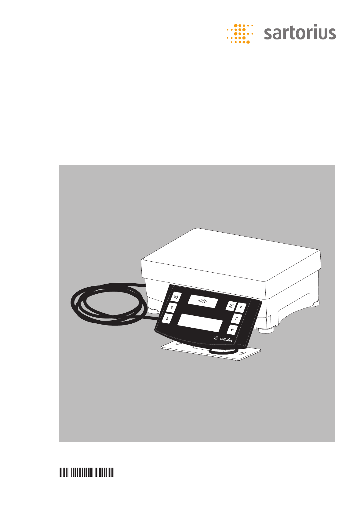
Sartorius PMA.Power
Model PMA35001-X
Electronic Paint-mixing Scale for Use
in Potentially Explosive Atmospheres
1000025334
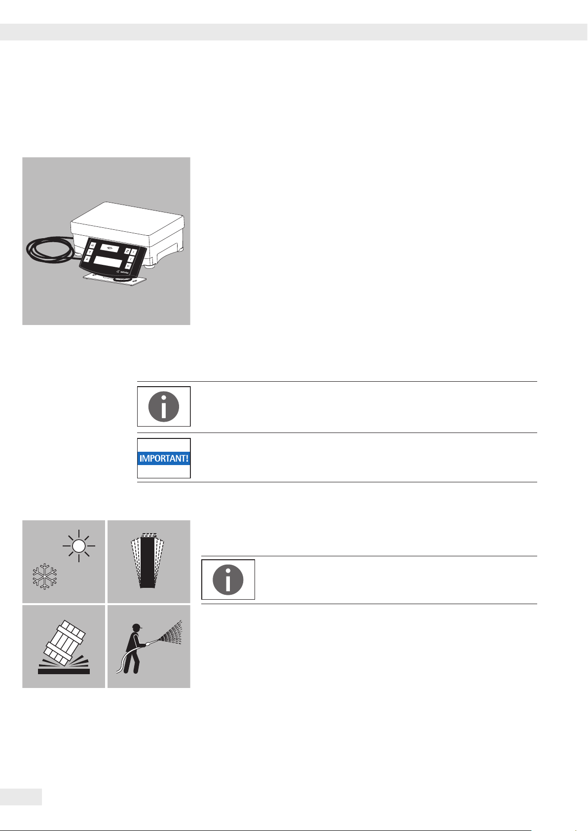
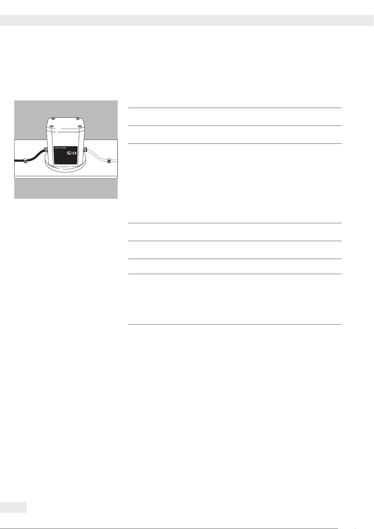
General View of the Equipment
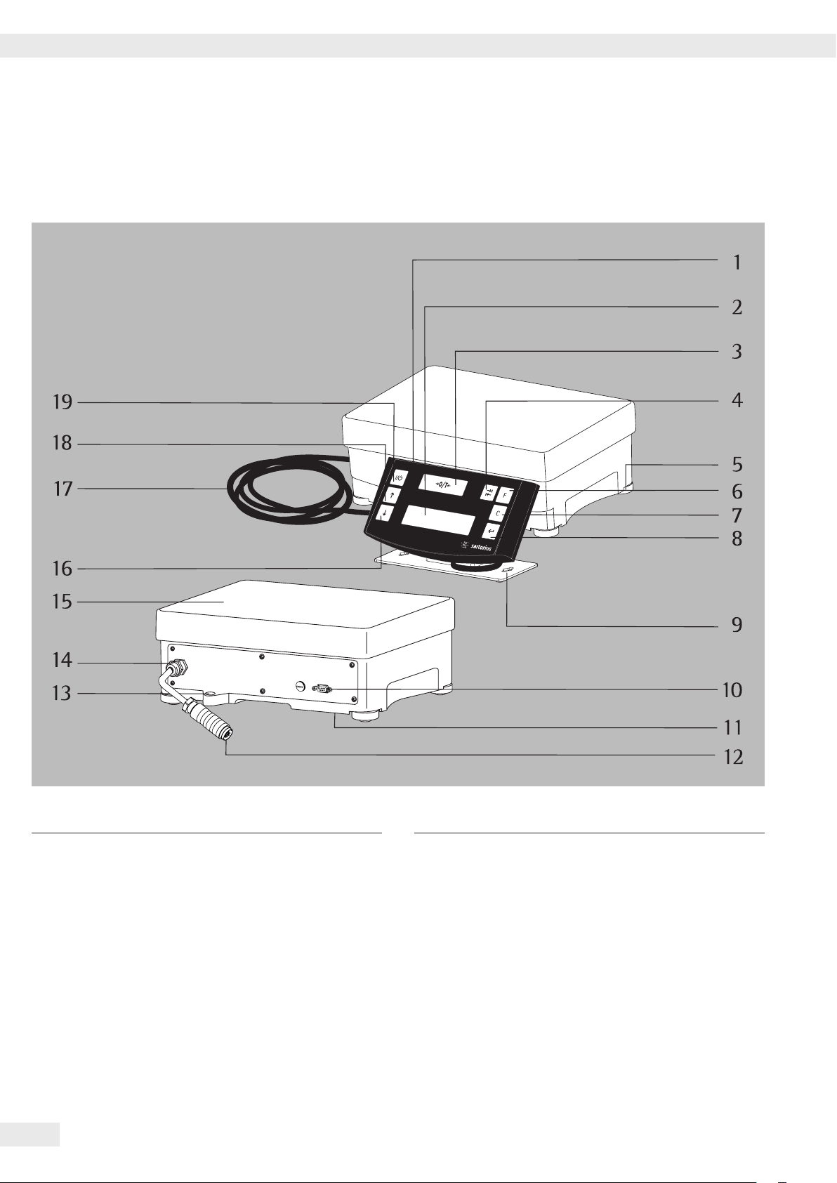
General View of the Equipment
Item Description
Display and control unit
2 Display
3 U key (Zeroing/Taring)
4 I toggle key depending on the menu setting:
You can configure the PMA35001 menu to enable
toggling between grams (g) and parts per pound (p).
5 Leveling foot
6 K factor key for paint-mixing applications
7 c key (Clear) and [REC] key
for paint-mixing applications
8 L [ENTER] key and [MEM] key for paint-mixing
applications
2 Operating Instructions PMA 35001-X
Item Description
9 Mounting bracket for display and control unit
10 Interface (D-SUB socket, 9-pin)
11 Grounding terminal
12 Adapter cable for the AC adapter
13 Level indicator
14 Cable connection
15 Load plate
16 S key: down
17 Power supply and data cable for the display and
control unit
18 R key: up
19 Q key (on/standby)

Contents
Contents
General View of the Equipment ..................................... 2
Contents ...................................................... 3
User Information ................................................ 4
Intended Use ................................................... 5
Safety Instructions .............................................. 5
Getting Started ................................................. 8
Equipment Supplied .......................................... 8
Installation ................................................. 8
Operation ..................................................... 12
Applications ................................................... 13
Calibration .................................................... 16
Menu Setting .................................................. 17
Error Messages .................................................22
Care and Maintenance ............................................ 23
Disposal ...................................................... 25
Interface Port .................................................. 26
Specifications .................................................. 27
Accessories .................................................... 28
Documents
EC Declaration of Conformity ..................................29
Safety Instructions ...........................................31
Certification: CE Type Test ..................................... 32
Verification of Intrinsic Safety, English ............................ 35
Certificate of Compliance ......................................40
Operating Instructions PMA 35001-X 3

User Information
User Information
About these Installation Instructions
t Please read these installation instructions carefully before putting the
equipment into operation for the first time.
t Make sure to follow the safety instructions.
t Keep these installation instructions in a safe place that is easily accessible to
allpersonnel who operate this equipment.
t If these instructions are lost, please contact Sartorius for a replacement or
download the latest manual from our website, www.sartorius.com.
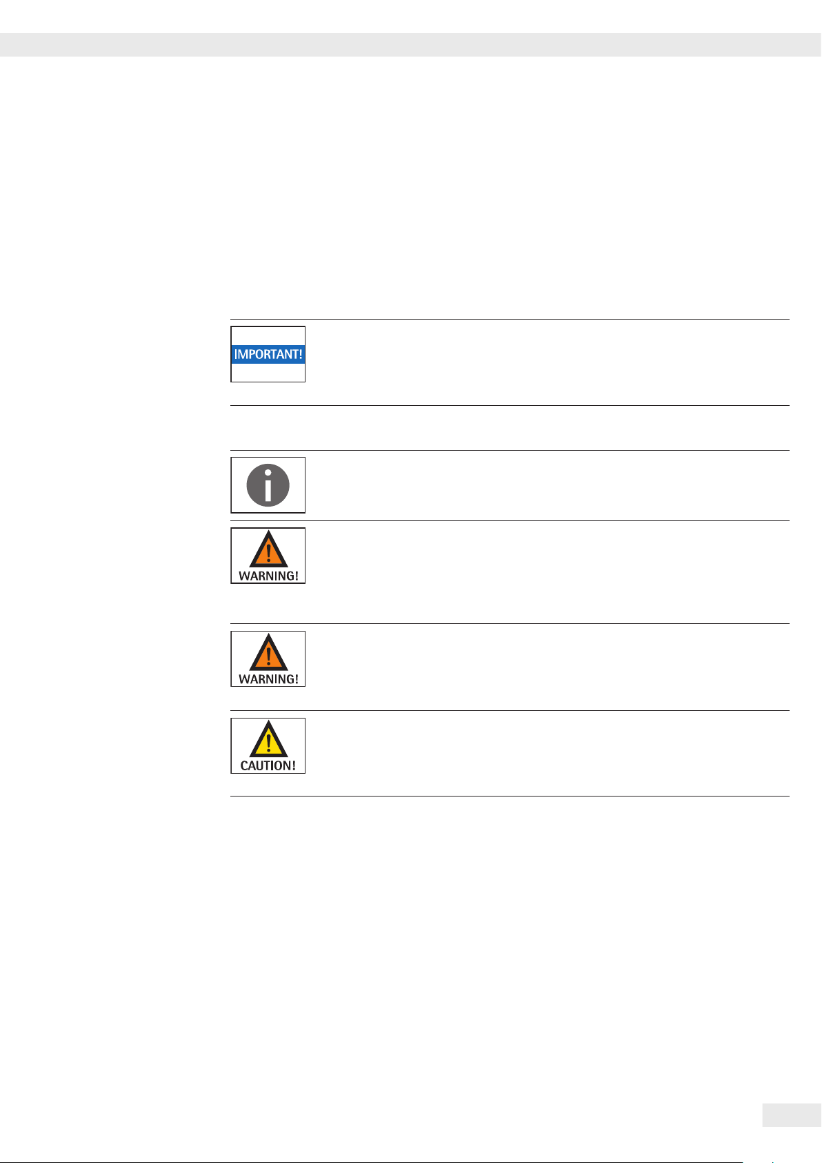
Warning/Danger Symbols
Warning/danger symbols used in these instructions:
This symbol identifies hazards which have a high probability of resulting in
death or serious physical injury if not avoided.
This symbol identifies hazards that can result in moderate or mild injuries if not
avoided.
These notes identify hazards associated with the risk of material damage.
This symbol identifies useful information and tips.
Explanation of Symbols
The following symbols are used in these instructions:
t Indicates a required action
4 Operating Instructions PMA 35001-X
y Describes what happens after you have performed a particular step
1. Perform steps in the specified order
2.
– Indicates an item in a list
Intended Usage
Intended Usage
The PMA35001-X is a scale designed for use in paint-mixing applications. The
scale can be operated via the keypad as a stand-alone device or using application
software (such as a paint-mixing program from a paint manufacturer) installed on
a connected PC.
If you wish to create your own application software, Sartorius can supply the
required drivers for Windows operating systems.
Make sure to read and store these installation instructions carefully before
installing and operating your paint-mixing scale.
Safety Instructions
This device meets stipulated safety requirements. Improper use or handling,
however, can result in damage and/or injury. The manufacturer is not responsible
for any damage caused by non-compliance with warnings or safety instructions.
– The requirements pertaining to applicable installation regulations must be
followed when using electrical equipment in systems and environmental
conditions with increased safety requirements.
Use of the paint-mixing scale is not permitted in legal metrology or in medical
areas or hazardous areas containing dust or explosive materials.
– The intrinsically safecolor-mixing scale has been manufactured in accordance
with the European standards of CENELEC (see “EC Type Examination
Certificate" in the appendix).
The color-mixing scale can be used with intrinsically safe Sartorius accessories
in Zone 1 areas. (see: “Verification of Intrinsic Safety", cert. no: 36953-761-60).
Operating Instructions PMA 35001-X 5
Safety Instructions
The IP protection rating of the color-mixing scale in accordance with EN 60529 is
IP 43.
The device must be handled carefully in accordance with the IP protection rating.
The environment must be suitably secured.
The color-mixing scale meets all requirements for electromagnetic compatibility
(EMC). Interference stronger than the maximum values specified in the standards
(see Declarations of Conformity) should be avoided.
The casing on all connection cables as well as the casing on the wires inside the
equipment housing are made of PVC. Chemicals that corrode this material must
bekept away from these cables.
None of the components of the color-mixing scale should be exposed to ambient
temperatures outside the range of 0°C to 40°C during operation. Sufficient
ventilation must be provided, in order to avoid excessive build-up of heat.
The equipment must only be used indoors. Avoid generating static electricity
onglass and plastic parts. The color-mixing scale must be connected to the
equipotential bonding conductor using a suitable low resistance method.
All electrical circuits are earthed and electrically connected to the metal parts of
the device.
– The scale must be checked for correct function and safety by a trained and
qualified person at appropriate intervals (e.g. checking the cable for damage).
– Operating personnel must be trained to recognize faulty operating states and to
be able to initiate the necessary safety measures.
Proceed with extreme caution when using pre-wired connection cables purchased
from other manufacturers, as the pin assignments may not be compatible with
Sartorius equipment.
Only use cables and cable lengths approved by Sartorius.
– The operator is solely responsible when using cables not supplied by Sartorius.
The scale should only be opened by trained personnel with the power
disconnected. Danger to life: do not touch conductive parts of the power supply
wiring!
6 Operating Instructions PMA 35001-X
The scale must be installed and operated in a way that ensures that the control
unit cannot be damaged (e.g., by falling objects).
If the control unit is damaged, disconnect the device from the power supply
immediately.
A defective device may only be repaired by trained service technicians in
accordance with Sartorius guidelines. Only original replacement parts should be
used. Always ensure that the equipment is disconnected from AC power before
performing any maintenance, cleaning, or repair work.
If the equipment is opened by anyone other than persons authorized by Sartorius,
all claims under the manufacturer's warranty are forfeited. If necessary, speak to
your dealer or the Sartorius Service Center.
Safety Instructions
Ex Zone 1 (Category 2 Equipment)
– In accordance with Directive 94/9/EC, the PMA35000-X model is a category 2
device, suitable for use in Zone 1 potentially explosive areas.
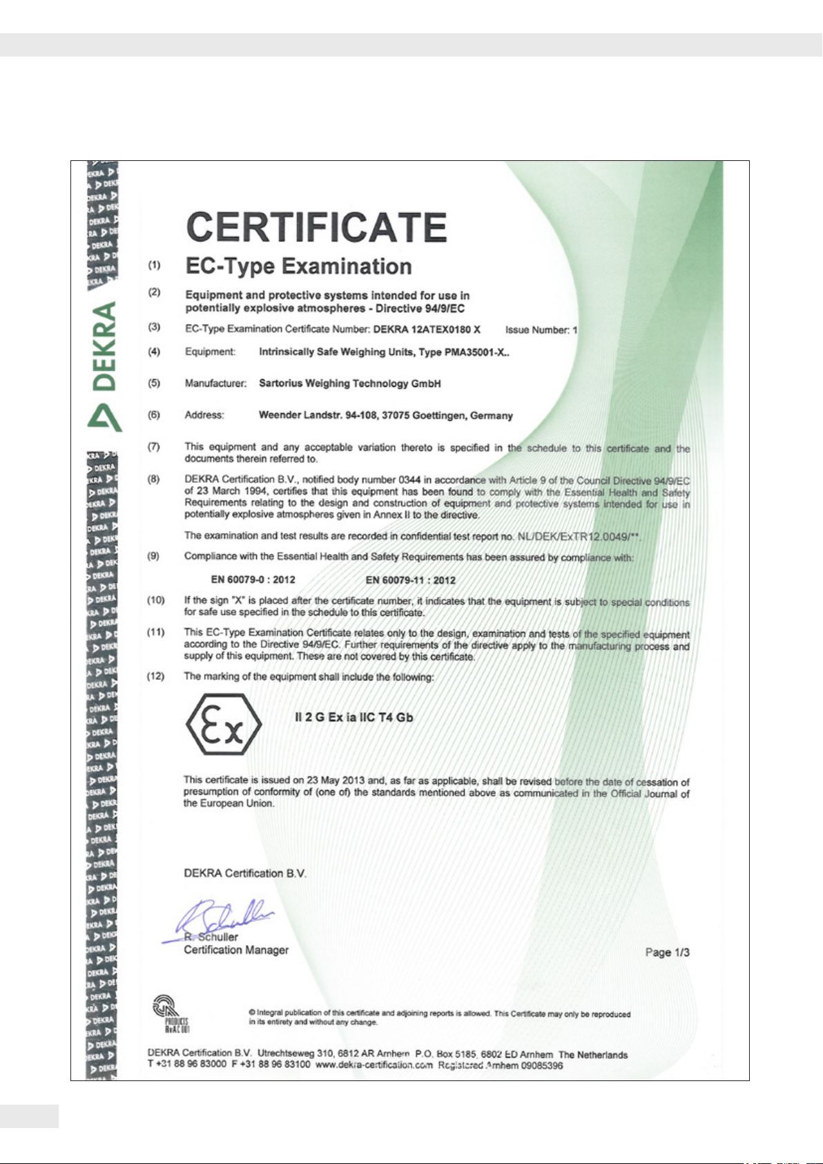
EC Type Examination Certificates: DEKRA 12ATEX0180 X ID code: II 2 G Ex ia
IIC T4 Gb
The scale may only be connected to supply voltages of 90 V to 264 V at a
frequency of 48–62 Hz.
If the device is used in Zone 1 potentially explosive areas outside the Federal
Republic of Germany, the relevant national electrical codes and safety regulations
must be observed. Ask the dealer or Sartorius Service Center about the guidelines
that apply in their country.
The following points must be followed:
This scale should only be opened by trained personnel with the power
disconnected.
The device is intended to be installed exclusively in locations that offer sufficient
protection against the penetration of solid foreign bodies or water. The safety of
the equipment is compromised by foreign bodies and water.
The terminal must be protected against damage and direct or indirect penetration
of water and foreign bodies (< 1 mm diameter).
Avoid generating static electricity on the front panel and plastic casing.
The equipotential bonding conductor of the devices must be connected properly,
according to commonly accepted technical standards.
Only clean the device as stipulated in the cleaning instructions.
The device must be protected from unnecessarily extreme temperatures, aggressive
chemical vapors, moisture, shocks, and vibrations. Note the connection data
(seeEC Type Examination Certificate of the device and/or the safety instructions,
drawing no. 36953-760-16).
Operating Instructions PMA 35001-X 7
Commissioning
°C
Commissioning
Equipment Supplied
t Unpack the scale carefully.
The scale comprises the following components:
– Scale
– Load plate – Display and control unit
t After unpacking the equipment, check immediately for any visible external
damage. If you detect any damage, proceed as directed in the “Safety
Inspections" chapter (page 23).
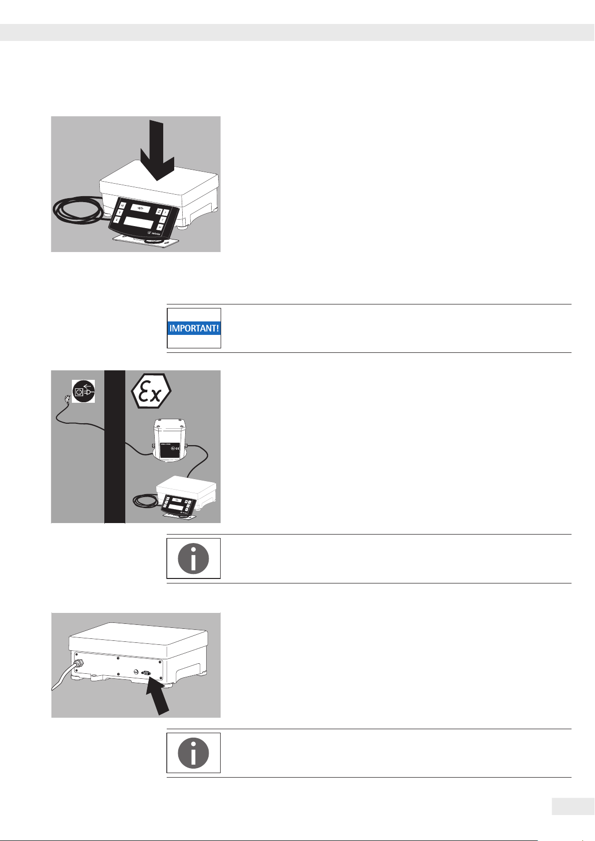
Installation
The color-mixing scale is authorized for use in Zone 1 potentially explosive areas
(see documents).
Make absolutely sure that the device is unplugged from the power supply
before connecting/disconnecting data transfer or control lines.
Installation Location
Choose a suitable location where the power supply will not be
exposed to drafts, heat radiation, moisture, or vibrations.
8 Operating Instructions PMA 35001-X
Installation
Setup Instructions
The following ambient conditions must be avoided when selecting the installation
location so you can work with extra speed and accuracy:
– Uneven installation location
– Drafts
– Extreme moisture or chemical vapors
– Extreme heat (e.g. avoid placing the terminal/control panel in close proximity to
a heater or exposing it to direct sunlight). Do not set up the device in a control
cabinet or in any other poorly ventilated location.
– Extreme vibrations
Follow all warnings and safety precautions.
– Before startup, make sure that the power cable is properly connected to the
power supply. In particular, the protective conductor must be connected to the
housing of the AC adapter. Connect all devices to the potential equalization
using a ground connection cable (not included) via the equipotential bonding
conductor terminals
Make sure that the cable gage conforms with national specifications.
Installation must be carried out properly by trained personnel and according to
commonly accepted technical standards.
– Only cables and cable lengths approved by Sartorius should be used, which
takeaccount of the limitations of the cable lengths due to the capacity and
inductance values (see appendix on EC Type Examination Certificate) and the
EMC behavior.
– The system should only be operated for the first time when it is certain that the
area is not potentially explosive.
– If deviations are evident during startup due to transport damage (no display,
nobacklighting, etc.), the system should be disconnected from the power
supply and service professionals should be contacted.
Make absolutely sure that the device is unplugged from the power supply
before connecting/disconnecting data transfer or control lines.
This explosion-protected color-mixing scale should be set up according to
commonly accepted technical standards. The applicable national electrical
codesand safety regulations for your particular country must be observed.
– Before commissioning the color-mixing system in potentially explosive areas, a
check must be carried out by or under the supervision of a qualified electrician
to ensure that the system is in good working order.
on the device.
Check whether or not the competent authorities (e.g. industrial supervisory board)
need to be informed. It is also necessary to carry out inspections of the system
during operation. Inspection intervals should be such that any significant defects
that may occur can be identified in good time. Inspections should be carried out
atleast once every three years. The applicable requirements and guidelines should
also be observed during operation.
Operating Instructions PMA 35001-X 9
Setup Instructions
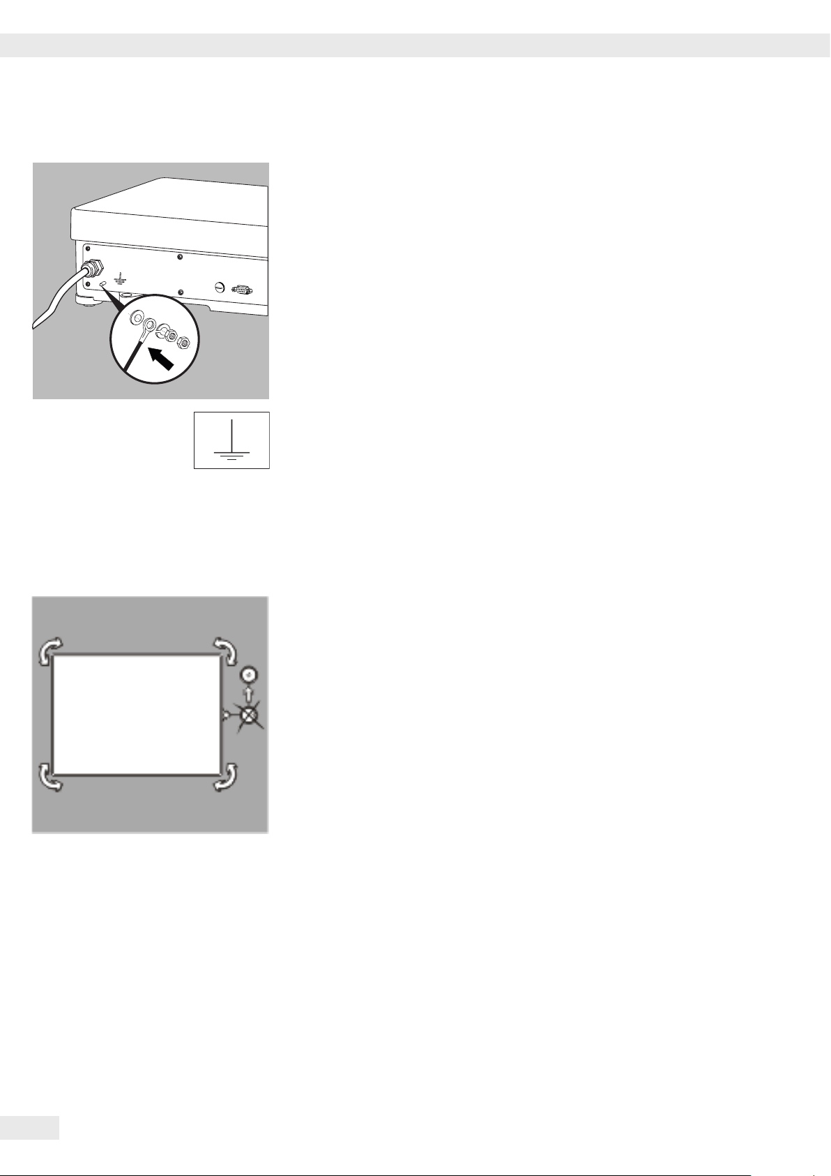
Connect the equipotential bonding connector:
Establish a low resistance connection with the color-mixing scale using a suitable
grounding cable with a gage of at least 4 mm2 (not included) via the equipotential
bonding conductor connections (PA) on the devices.
Installation must be carried out properly by trained personnel and according to
commonly accepted technical standards.
If deviations due to transport damage are evident during startup (e.g. no display,
no backlighting), the system should be disconnected from the power supply and
service professionals should be contacted.
Leveling the Weighing Platform
Purpose:
– To compensate for unevenness at the place of installation
– To ensure that the equipment is placed in a perfectly horizontal position for
consistently reproducible weighing results. Always level the weighing platform
again any time after it has been moved to a different location.
t Level the weighing platform using the four leveling feet. Turn the feet until the
air bubble is centered in the level indicator.
t Ensure that all leveling feet are resting securely on the work surface.
y Each of the leveling feet must support an equal load.
y Adjusting the leveling feet:
To raise the weighing platform, extend the leveling feet (turn counterclockwise). To lower the weighing platform, retract the leveling feet (turn clockwise).
10 Operating Instructions PMA 35001-X
Installation
t Place the weighing pan on the balance.
Connecting the Device to AC Power
Power is supplied via a Sartorius AC adapter. Make sure that the voltage rating
printed on this unit matches the voltage at the place of installation.
If the stated supply voltage or the plug design of the power cord does not comply
with the standard you use, please inform your nearest Sartorius representative or
your supplier. Use only original Sartorius adapters: A list of permitted models can
be found in the Accessories (Options) chapter on page 28. The use of cables from
other manufacturers, even if these units have a registered approval rating from
anational testing laboratory, requires the consent of a qualified technician.
When operating the scale in Zone 1 potentially explosive areas, follow the
current standards and regulations for the installation of devices in Zone 1.
In order to connect the equipment to the power supply, use a correctly installed
wall outlet with a protective grounding conductor (PE) and a fuse of a maximum
16 A.
t Connection of the power supply outside of the potentially explosive
atmosphere or mechanically secured (refer to “Safety Information" documents).
t Plug the power cord on the Sartorius AC adapter into the wall outlet (mains).
Observe all warnings and safety precautions.
See also: “Safety Instructions” documents.
Connection of Peripheral Devices:
When installing the device in potentially explosive atmospheres of Zone 1,
connectors may only be plugged in or disconnected in a currentless/dead-voltage
state.
Disconnect the scale from the power line before connecting peripheral devices
(printer, PC) to the interface port of the device.
t When connecting peripheral devices (printer, PC) to the scale's interface port,
make sure that the screws on the data plug are securely tightened.
Observe all warnings and safety precautions.
See also: “Safety Instructions” documents.
Operating Instructions PMA 35001-X 11
Operation
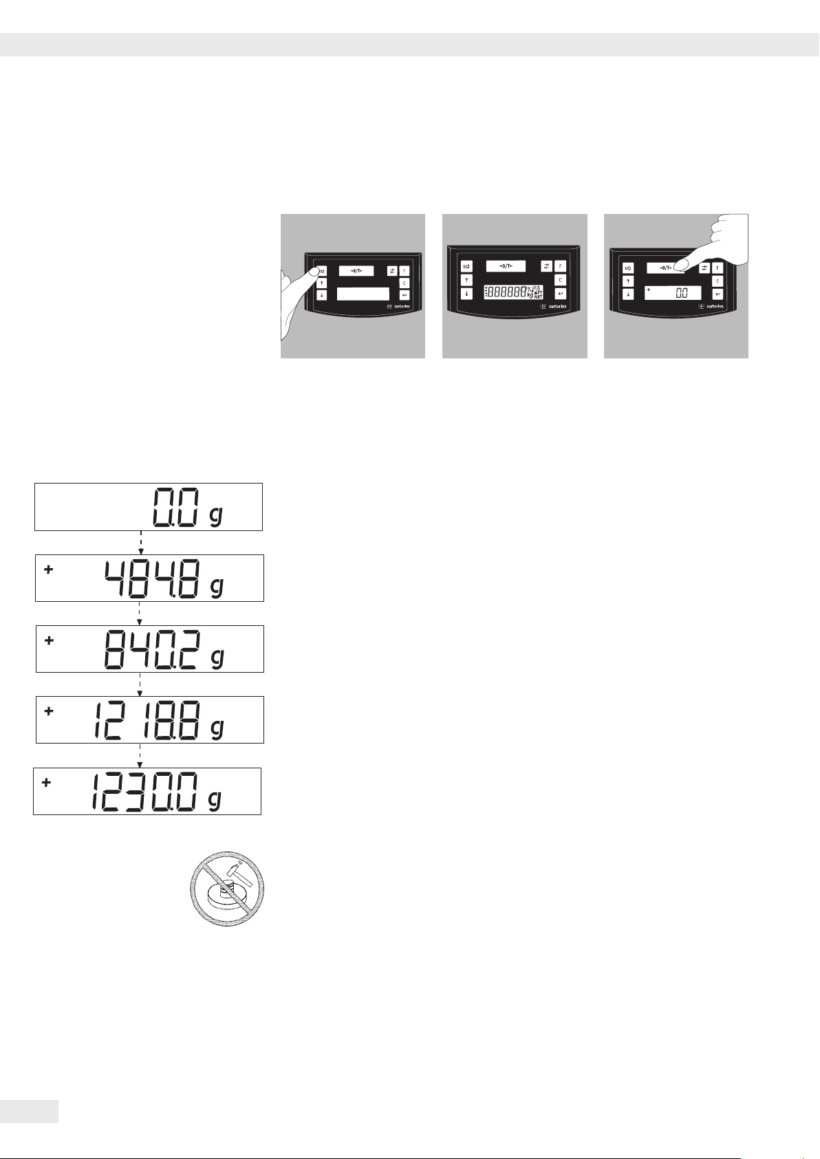
Operation
Press the Q key to turn
on the scale.
Weighing
Place an empty paint can on the load plate.
Press the U key (Zero/Tare) (3).
The display shows “0.0 g.” Pour the first component of your formula into the can
and read off the weight when the stability symbol (in this example) “g" is displayed.
Add the other components up to the desired weight (formula).
Remove the filled paint can from the load plate.
Once the scale has been
turned on, it will run an
automatic self-test. This
ends when the display
shows 0.0 g.
If a different value is
displayed: Tare the
scale using the U
key (Zero/Tare).
12 Operating Instructions PMA 35001-X
Never use a hammer to close a paint can while is it still on the load plate, as this
will damage the weighing system.
The weighing system will get damaged!
Applications
Applications
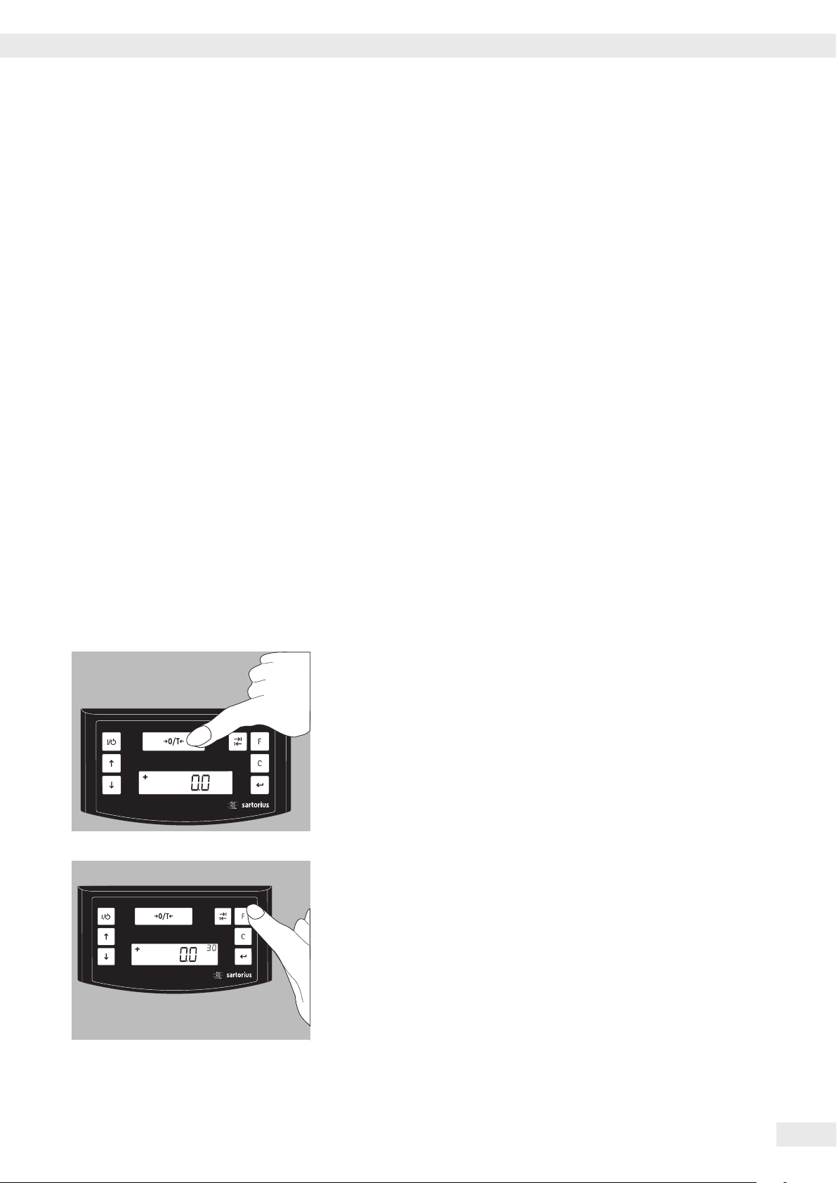
Formulation Mode (Calculation by a Factor)
This mode enables you to weigh in amounts that are smaller or larger than that of
your basic formula for a specific paint color (e.g. 250 ml of a 1 l formula). Press the
K factor key to select the desired factor (quantity):
By pressing the R key: up
or S key: down
the value can
be modified – in 0.1 increments for factors of 1.0 to 6.0
or – in 0.01 increments for a factor of up to 1.0.
Note:
A flashing n arrow on the display indicates that the weight value displayed is not
valid in legal metrology (i.e. not legal for trade).
Example:
As you pour in the components of your formula, the weight is displayed in “g.”
Let'ssuppose you want to weigh out 3 kg of a 1kg basic formula, and you don't
want to have to manually recalculate the individual components of the formula.
The basic formula for 1 kg is:
250 g 1st component
+ 250 g 2nd component
+ 500 g 3rd component
Total: 1000 g
1. Place the empty container on the load plate and tare the scale.
2. Press the F factor key repeatedly to set the factor to “3.0" for this example.
Operating Instructions PMA 35001-X 13
Applications
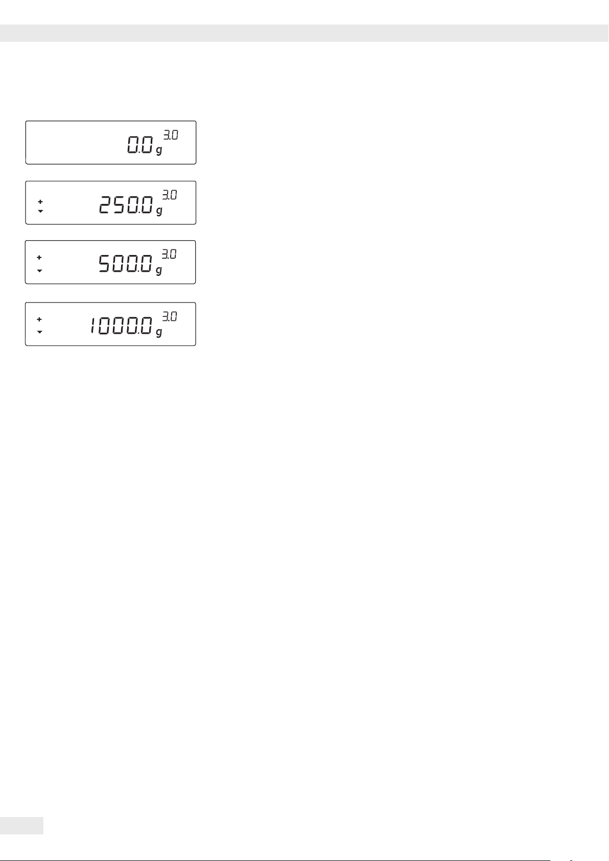
3. A “3.0" appears next to the weight readout.
4. Slowly pour in the first “250 g" of component until the display shows “250 g.”
5. Pour in the second “250 g" component until “500 g" is displayed.
6. Pour in the last “500 g" component until “1000 g" is displayed.
This concludes the recalculation example. According to the display, exactly
1000 g was poured in, but the paint in the container weighs 3 kg in accordance
with the factor you selected.
The procedure is the same for any other conversion factor.
Weighing Using the Recalculation Mode
Let's suppose that you poured in too much of one color component for a given
formula (in this example, a 4-component recipe).
This example further assumes that you previously poured in all of the other
amounts exactly according to each of the values you entered and saved by pressing
the L key [MEM]. Press the S key to start the recalculation program; “C" flashes
on the display. Press the S key to correct the value so that it matches the amount
specified in the formula. Press the L key [MEM]; the scale returns to component 1
and automatically calculates the amount to be added for each of the components
that were already poured. The display shows the amounts required to correct the
formula up to the point at which the overpour occurred.
After the correction has been completed, you can continue filling the remaining
components. The same factor is used.
Note:
You can correct overpours as often as needed.
Keep in mind that the total quantity of paint at the conclusion of filling increases
each time you correct a component. Press the c key to check how much the
correction factor for the total quantity will be. “C" stands for “Correction factor."
14 Operating Instructions PMA 35001-X
An n arrow on the display indicates that the weight value displayed is not valid in
legal metrology (i.e. not legal for trade).
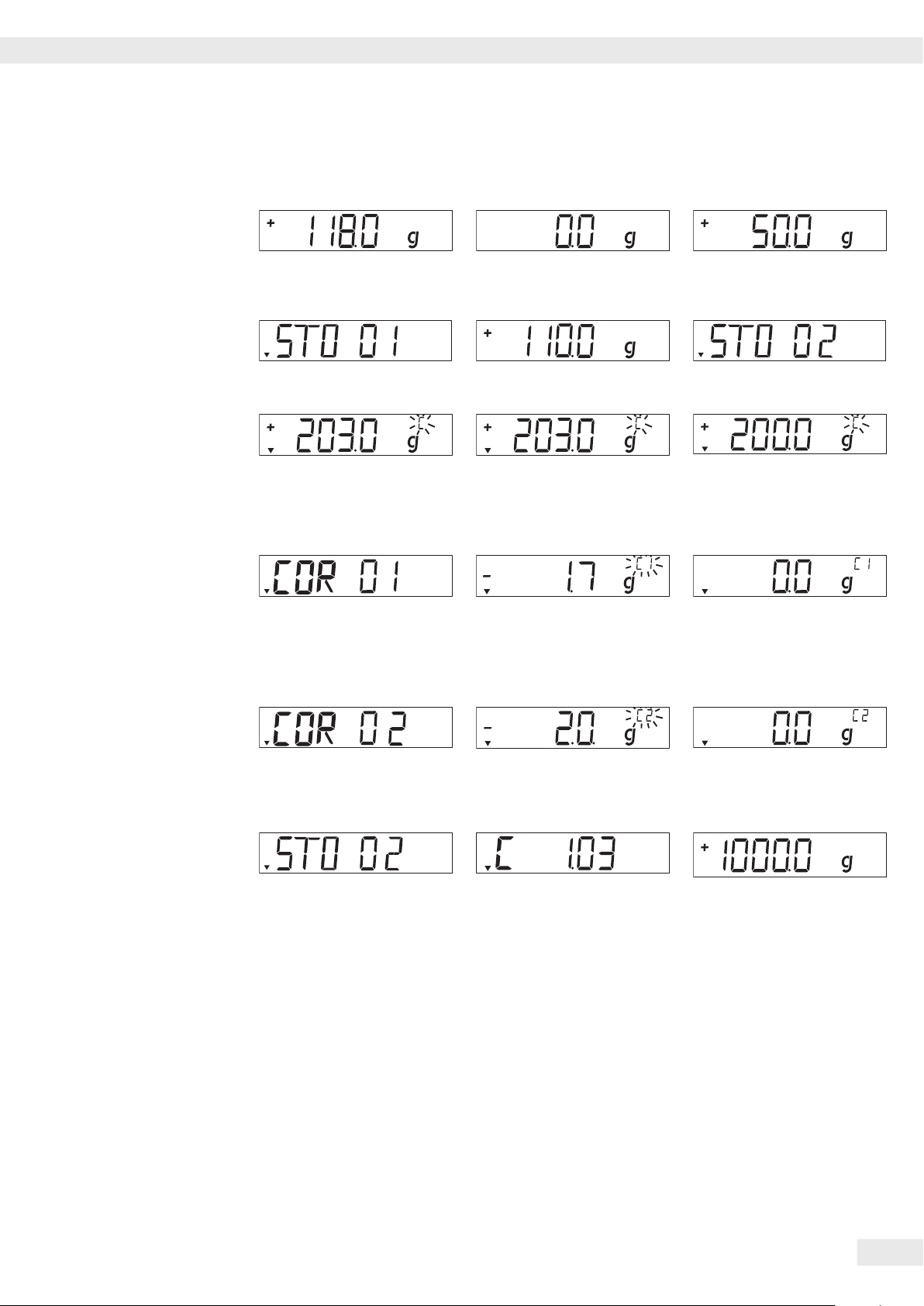
Example (Cumulative Weighing)
Applications
1. Center an empty paint can
on the load plate.
+ 118.0 g
4. Press the L key [MEM]
STO 01
7. Add the third component
+ 203.0 g
Oops! You poured in too
much. The correct value for
the formula is 200.0 g.
10. Press the L key [MEM]
COR 01
2. Press the U key
(Zero/Tare).
0.0 g
5. Add the second component
+ 110.0 g
8. PPress the S key to start
the recalculation mode.
A »C« (“Correction”) flashes
on the display.
11. Add the required amount of
the first component. “C1”
appears on the display.
–1.7 g.
3. Add first component.
+ 50.0 g
6. Press the L key [MEM]
STO 02
9. Press the S key repeatedly
to correct the value.
+ 200.0 g
12. Add until value reaches
0.0 g.
0.0 g
13. Press the L key [MEM]
COR 02
16. Press the L key [MEM].
The scale returns to the
formulation program. »C«
is no longer displayed.
+ 200.0 g.
14. Add the required amount
of the second component.
“C2” appears on the display.
2.0 g
17. Press the c key (7) [REC]
to view the factor by which
the total weight will exceed
the original target.
(C = “Correction;”
in this example, 1.03).
(Total weight = original
target + correction factor)
15. Add until value reaches
0.0 g.
0.0 g
18. Add fourth component
+1000.0 g
This concludes the
recalculation example.
Operating Instructions PMA 35001-X 15
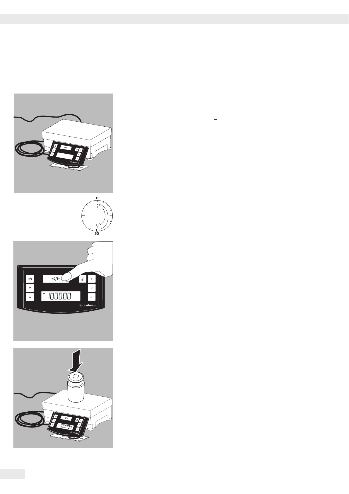
Adjustment
Adjustment
You can calibrate/adjust the scale by pressing the U key (Zero/Tare).
Calibration weight: 10000 g; precision: +2%.
Always allow approximately 30 minutes for the scale to warm up after connecting it
to AC power and before performing calibration/adjustment.
Press and hold the U key (Zero/Tare) for 2 seconds; “10000" is displayed.
Release the key.
Center the calibration weight on the load plate. Adjustment is performed
automatically.
Remove the calibration weight.
16 Operating Instructions PMA 35001-X

Menu Settings
Menu Settings
Accessing the SETUP Menu
Example:
Menu Item: Adapting the Scale to the Installation Point
t Hold down the L key [ENTER] for approximately 2 seconds; “SETUP" is
displayed (level one).
t Use the RS keys to select the desired menu item for level one.
t Press the L key [ENTER] to select the next menu level (level two).
t Call up the desired menu item in level two.
Use the RS keys to select the desired menu item.
t Use the L key [ENTER] to select the next menu level (level three).
t The third level menu is displayed. Use the RS keys to select the desired menu
item.
t Press the L key [ENTER] to select the next menu level (level four).
t Call up the desired menu item in level four. Use the RS keys to select the
desired menu item.
(This concludes the example.)
t Press the L key [ENTER]; “o" is displayed, indicating that this new item is set.
t Press the c key (Clear) repeatedly to exit the menu.
Note:
Contact your local Sartorius office for a detailed list of the menu codes.
Operating Instructions PMA 35001-X 17

Menu Settings
Configuring the Main Menu Settings
Hold down the L key [ENTER] for approximately 2 seconds; “SETUP” is displayed (level 1).
Level 1
SETUP
Language Setting
Level 1 Level Setting
LANGUAGE Press the R key to select LANGUAGE
Press the L key [ENTER]
o GERMAN Press the RS keys to select a language
ENGLISH Press the L key [ENTER];
FRENCH o indicates the active setting
ITALIAN Press the c key (Clear) repeatedly to exit
etc. the menu
Default Unit: Standard and Grams/Parts per Pound
The default setting that is active when the scale is switched on can be found under
“SETUP > SCALE > UNIT” and SETUP>SCALE>SET:
Level 1 Level 2 Level 3 Level 4 Setting
SETUP Press the L key [ENTER]
SCALE Press the L key [ENTER]
UNIT Use the RS keys to select e.g. “SET”
GRAMS Press the L key [ENTER]
KG
o PT./PD. Use the RS keys toselect e.g. “STANDARD”
SET Press the L key [ENTER]; o indicates
o STANDARD the new code is set
Press the c key (Clear) repeatedly
to exit the menu
I Activating the Toggle Key
When the toggle key I (6) is active, you can use it to toggle the weight unit between grams
and parts per pound or to toggle between the decimal places. The unit is toggled each time the key is
pressed.
Level 1 Level 2 Level 3 Level 4 Setting
SETUP Press the L key [ENTER]
APPLICATION Use the RS keys to select “APPLICATION”
Press the L key [ENTER]
TOGGLE Use the RS keys to select “TOGGLE”
OFF Press the L key [ENTER]
o ON Use the RS keys to select “ON”
Press the L key [ENTER]; o indicates
the active setting
Press the c key (Clear) repeatedly
to exit the menu
18 Operating Instructions PMA 35001-X

Menu Settings
I Configuring the Toggle Key Function
Pressing the toggle key I toggles the scale between the default unit (see previous page) and the unit
defined as follows under SETUP > APPLICATION > UNIT.
Level 1 Level 2 Level 3 Level 4 Setting
SETUP Press the L key [ENTER]
APPLICATION Use the RS keys to select
“APPLICATION”
UNIT Press the L key [ENTER], press S to
select “UNIT” and press L [ENTER] to
confirm.
o PT./PD. Use the RS keys to select the desired
unit; e.g., “GRAMS”
GRAMS Press the L key [ENTER]; o indicates
the active setting
Press the c key (Clear)
Activating the “LOCK” Function
The LOCK function protects the scale from unauthorized use. When this function is active, the scale
readout shows weight values only when there is active communication between the scale and a PC.
If communication is interrupted, the readout goes blank and the display shows a padlock symbol. The
LOCK function is activated under “Extras.”
Level 1 Level 2 Level 3 Level 4
SETUP Press the L key [ENTER]
EXTRAS Use the RS keys to select “EXTRAS”
Press the L key [ENTER]
LOCK Use the RS keys to select “LOCK”
Press the L key [ENTER]
OFF Use the RS keys to select ON and
o ON press L to confirm
Press the c key (Clear) repeatedly to exit
the menu.
Operating Instructions PMA 35001-X 19

Menu Settings
Configuring Password Protection
In addition to the LOCK function, you can configure password protection for additional security.
With this feature, the LOCK function can be deactivated only by entering the valid password.
The password is numeric and can have up to 6 digits. Use the RS keys to select the digits
(0 through 9) for your password. The password is hidden on the display; only dashes (“------”) are
shown. The first dash flashes to prompt input. Press the RS keys to select the desired digit (0 to 9)
and then press the L key [ENTER]. The digit is stored and the second dash flashes on the display.
Repeat the input procedure as described for the first digit. To store a space as a character in the
password, press the L key [ENTER] while the corresponding dash is flashing.
Once all 6 characters have been stored, press the L key [ENTER] to enter the password.
Note:
Keep a copy of your password in a safe place.
The LOCK function can be deactivated only with this password.
Level 1 Level 2 Level 3 Setting
INPUT Use the RS keys to select “INPUT”
PASSWORD Press the L key [ENTER]
Press the L key [ENTER]
PW.NEW Use the RS keys to select “PW.NEW”
-------- Enter the password and press the
L key [ENTER]
Press the c key (Clear) repeatedly to exit
the menu
Changing the Password
To define a new password, the existing password must first be entered correctly under “PASSWORD.”
“PW.OLD” prompts this input. Once the old password is entered correctly, the “PW.NEW” prompt is
shown automatically. Enter the new password or press L at each position to confirm.
The display shows spaces.
Note:
Entering 6 spaces deletes the password, which deactivates the password function.
Level 1 Level 2 Level 3 Setting
INPUT Use the RS keys to select “INPUT”
PASSWORD Press the L key [ENTER]
PW.OLD Press the L key [ENTER]
-------- Enter the old password
PW.NEW After the old password has been entered
correctly, “PW.NEW” is displayed.
-------- Enter the desired password and press
the L key [ENTER]
Press the c key (Clear) repeatedly to exit
the menu
20 Operating Instructions PMA 35001-X

Menu Settings
Configuring the Text Length (“LONG” or “SHORT”)
You can define the length of the operator guidance texts shown on the display.
Level 1 Level 2 Level 3 Level 4 Setting
SETUP Press the L key [ENTER]
EXTRAS Use the RS keys to select “EXTRAS”
Press the L key [ENTER]
TEXTS Use the RS keys to select “TEXTS”
Press the L key [ENTER]
LONG Use the RS keys to select “SHORT”
o SHORT and press L to confirm
Press the c key (Clear) repeatedly
to exit the menu
Resetting the Scale (“RESET”)
You can restore the factory settings on the scale.
Note:
If you have activated the password function, this feature is password-protected.
Level 1 Level 2 Level 3 Level 4 Setting
SETUP Press the L key [ENTER]
RESET Use the RS keys to select “RESET”
Press the L key [ENTER]
MENU Use the RS keys to select “MENU”
Press the L key [ENTER]
YES Use the RS keys to select “YES”
o NO Press the L key; factory settings are
restored and “MENU” is displayed
Press the c key (Clear) repeatedly
to exit the menu
Code Settings
Select the “CODES” setting to have menu items identified by numeric codes (1.1.1.1.) rather than texts.
Level 1 Level 2 Setting
LANGUAGE Press the R key to select “LANGUAGE”
Press the L key [ENTER]
GERMAN Use the RS keys to select “CODES”
etc. Press the L key [ENTER]; o indicates
o CODES the active setting
Press the c key (Clear) repeatedly
to exit the menu
Note:
Contact your local Sartorius office for a detailed list of the menu codes.
Operating Instructions PMA 35001-X 21

Error Codes
Error Codes
Problem Cause Remedy
No segments appear
onthe weight display
The weight readout
shows “Low"
The weight readout
shows “High"
The weight readout
changes constantly
The weight readout is
obviously incorrect
No weight value is
shown and the padlock
symbol
is displayed
– No AC power is
available
– No load plate on the
scale
– Weighing capacity
exceeded
– The setup location
isunstable
– Excessive vibration
ordraft
– The sample is not
stable
– Scale not tared before
weighing
– Communication
between scale and PC
has been interrupted,
activating the LOCK
function
– Check the AC power
supply
– Position the load plate
– Unload the scale
– Change the setup location
– Make the necessary
adjustment via the scale
operating menu
(see “Menu Settings")
– Tare before weighing
– Access the menu to make
the necessary adjustment
and switch off the LOCK
function
– Check the connection
22 Operating Instructions PMA 35001-X
Care and Maintenance
Care and Maintenance
Service
Regular servicing by a Sartorius technician will ensure continued functional safety.
Sartorius offers its customers service contracts with regular maintenance intervals
ranging from 1 month to 2 years.
The maintenance interval depends on operating conditions and requirements.
Repairs
Disconnect defective equipment from power supply immediately.
Repair work must be performed only by authorized Sartorius service technicians
using original replacement parts. Repairs performed by untrained persons may
result in considerable hazards for the user.
Safety Inspections
Safe operation of the device is no longer ensured when:
– the device has visible damage or is no longer working;
– it has been stored for a relatively long time under unfavorable conditions.
In this case, notify the Sartorius Service Center. Maintenance and repair work
mayonly be performed by authorized service technicians who have access to the
required maintenance manuals and instructions and have attended relevant service
training courses. If you are sending your scale to be repaired:
t remove as much paint residue as possible and disconnect all cables before
sending, in order to avoid any further damage;
t enclose a description of the error.
Cleaning
Prevent moisture from penetrating the interior.
Do not use aggressive cleaning agents. Never use concentrated acids,
alkalisolutions or pure alcohol to clean the equipment.
Spraying the device with water or blowing it with compressed air is not
permissible.
t Turn off the device before cleaning the control unit, since touching the screen
could trigger unwanted inputs.
t Use a damp, lint-free cloth to clean the device.
Operating Instructions PMA 35001-X 23

Care and Maintenance
Do not apply any cleaning agents to ID labels or printed surfaces.
Corrosive Environment
t Remove all traces of corrosive substances from the device on a regular basis.
Storage and Shipping Conditions
– Permissible storage temperature: -10 °C … +60 °C
24 Operating Instructions PMA 35001-X

Disposal
Disposal
The packaging is made of environmentally friendly materials that can be used as
secondary raw materials. If you no longer require the packaging, you can dispose
ofit free of charge in Germany through the Vfw dual system (contract number
D-59101-2009-1129). Otherwise you should dispose of the material in accordance
with the waste disposal regulations that are applicable in your area. The device,
including its accessories and batteries, should not be disposed of as household
waste. It should instead be recycled as electric/electronic equipment. For more
information regarding disposal and recycling, please contact our local service
representatives. Our partners listed on the following website will also be able to
provide assistance within the EU:
1) Go to http://www.sartorius.com.
2) Select the “Services" tab.
3) Then select “Disposal Information.”
4) Addresses for the local Sartorius disposal contacts can be found in the PDF files
available for download on this page.
Sartorius will not take back equipment contaminated with hazardous materials
(ABC contamination) – either for repair or disposal.
Detailed information, including service addresses for returning your device for
repair or disposal, can be found on our website (www.sartorius.com) or requested
from a Sartorius Service Center.
Serial Number Coding
The manufacture date of this device is encoded in the serial number.
The format is as follows: YMM x x x x x
Y Year
1 2000–2006
2 2007-2013
3 2014–2020, etc.
The Y column indicates the year group, which covers a period of 7 years.
Withineach year group, the months (M M) are counted up from 13.
Year: 2013 2014 2015 2016 2017 etc.
MM: 85-96 13-24 25-36 37-48 49-60 etc.
Example: 288xxxxx (April 2013). “xxxxx" is a consecutive number, increasing
by one every month.
Operating Instructions PMA 35001-X 25
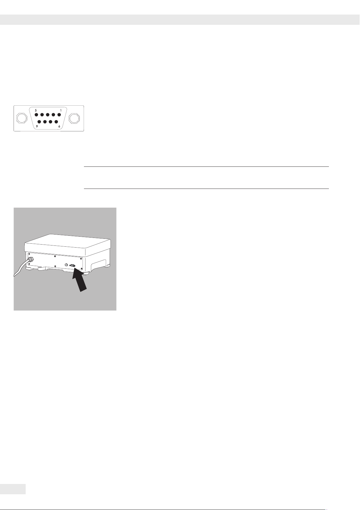
Interface Port
!
Interface Port
Pin assignment
9-pin data output (socket):
Pin 2: (RXD) Receive data
Pin 3: (TXD) Transmit data
Pin 4: (DTR) Data terminal ready
Pin 5: (GND) Ground
Pin 6: not used.
Pin 8: Clear to send (CTS)
Make sure to observe the safety instructions.
t Remove the protective cover from the interface port.
Keep the protective cover in a safe place.
y Replace the interface cover when storing or shipping the scale.
26 Operating Instructions PMA 35001-X

Specifications
Specifications
Model PMA 35001-X
Weighing Capacity g 35000
Readability g 0.1
Tare range (subtractive) g -35000
Linearity g ≤±0,2
Stability range (configurable in menu) Digit 0.25 to 4
Humidity class F non-condensing
Permissible ambient operating temperature range °C 0 to +40
IP protection IP 43, in accordance with EN60529/IEC60529
Load plate dimensions mm 350 + 240
Scale housing (WxDxH) mm 350 + 243 + 132,5
Net weight, approx. kg 11.4
External calibration weight kg 10 (accuracy class F2 or better)
Interface RS232
Format 7-bit ASCII, 1 start bit, 1 or 2 stop bits
Parity Even, odd, none
Transmission rates 1200 to 38,400 bps
Handshake Software or hardware
Power consumption VA Average: 8, max. 16
Mains Connection V 100 – 240 V ~
Voltage frequency Hz 50 – 60
Device ID (explosion protection) II 2G Ex ia IIC T4 Gb
DEKRA 12ATEX0180 X The terminal/control panel is
suitable for use in potentially explosive areas in
accordance with Directive 94/9/EC
Zone1 (devices in category 2)
Ambient conditions
Environment For indoor use only
Ambient temperature: Storage and shipping -10 °C … +60 °C
Ambient temperature: Operation 0 °C … +40 °C
Highest relative humidity: 80 % for temperatures up to 31 °C, decreasing linearly up to
50 % relative humidity for 40 °C
Safety of electrical equipment
Electromagnetic compatibility
Defined immunity to interference:
Limitation of emissions:
as per EN 61010-1:2010
Safety requirements for electrical equipment for
measurement, control, and laboratory use — Part 1:
Generalrequirements
as per EN 61326-1:2006
Electrical equipment for measurement, control, and laboratory use — EMC requirements — Part 1: General requirements
Industrial areas
Class B: Suitable for use in residential areas and areas that
are directly connected to a low voltage network
Operating Instructions PMA 35001-X 27
Accessories
Accessories
AC adapters
ATEX certified for Europe:
AC adapter for use inside of potentially explosive area
ATEX certified for Europe:
AC adapter for use outside of potentially explosive area
FM certified for the USA:
AC adapter for use inside of potentially explosive area
FM certified for the USA and Canada:
AC adapter for use outside of potentially explosive area
CSA certified for Canada:
AC adapter for use inside of potentially explosive area
Safety barrier
Data communication cable with integrated
energy limiting unit for direct communication (RS232) from
thePC to a Sartorius scale in potentially explosive atmosphere
xx = different cable lengths available (8m, 15m, 30m)
YPSC01-X
YPSC01-Z
YPS02-XUR
YPS02-ZKR
YPS02-XKR
YELU01-ZMxx
In-use dust cover
Data communication cable (2 m) YCC01-0047M2
YDC01PMA
28 Operating Instructions PMA 35001-X

EC Declaration of Conformity
Operating Instructions PMA 35001-X 29

ECDeclaration of Conformity
30 Operating Instructions PMA 35001-X
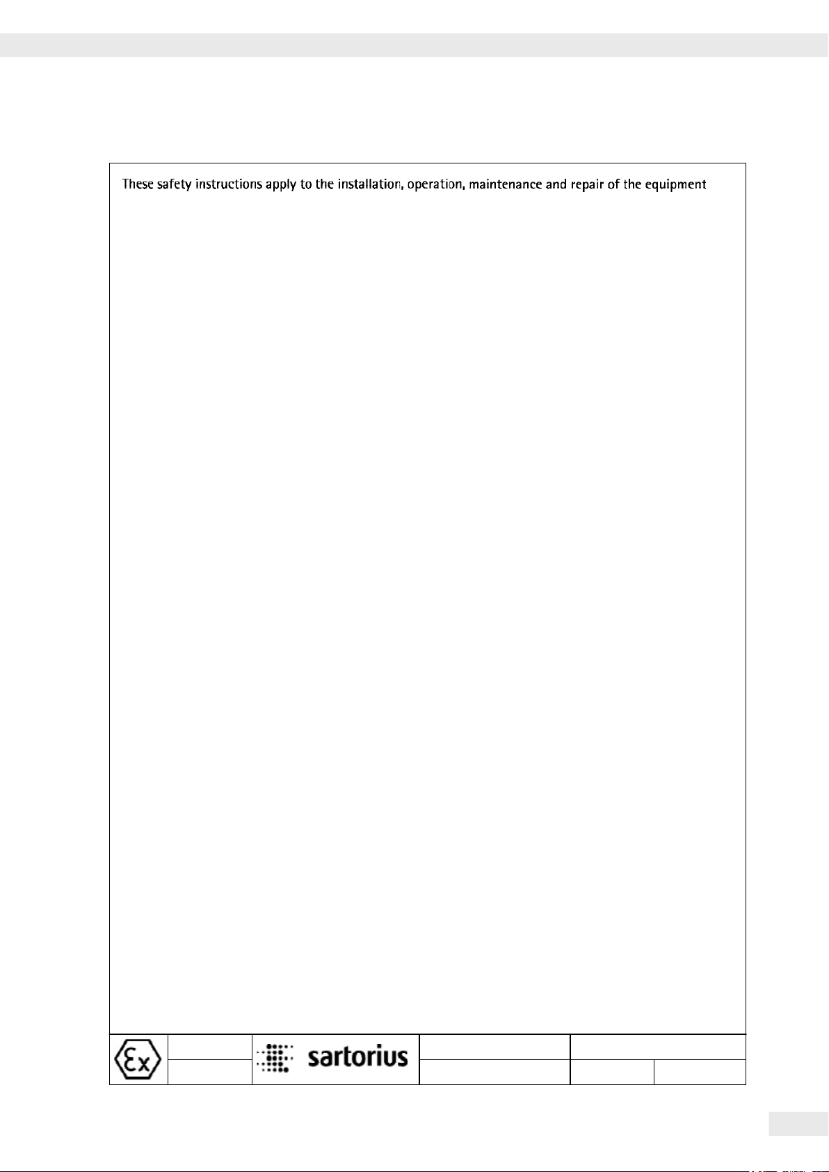
Safety Instructions
1) The equipment must be installed, operated, maintained and repaired by a qualified technician in compliance
with applicable laws, rules and regulations, ordinances and standards. In particular, be sure to conform to the
European Standards EN 60079-14 (Explosive atmospheres – Part 14: Electrical installations design, selection
and erection). For more information see „Verification of Intrinsic Safety“ 36953-761-60 (ATEX) and „Control
Drawing“ 36953-761-07 (for use in the USA and in Canada).
Installation, maintenance, cleaning and repair work may only take place with all power disconnected from the
equipment. Do not plug in or disconnect the cable in potentially explosive atmospheres.
2) Be sure to follow the installation, operating, maintenance and servicing instructions given in the manuals
supplied.
3) The equipment shall be installed in such a way that it is protected against the entry of solid foreign objects or
water capable of impairing the safety of the apparatus. Reduce the risk of mechanical damage to a minimum.
4) The equipment must be powered by a suitable certified/approved power supply/battery pack with intrinsically
safe circuits as described in the certificate of this equipment.
5) Exposure to UV radiation is not allowed! Avoid exposure to direct sunlight.
6) The connecting cables of the display unit must be protected against damage and stress caused by strain.
7) Prior to opening the equipment, disconnect the power supply or make sure that there is no potentially
explosive atmosphere or any other explosion hazard in the surrounding area!
8) The data cables connected to the equipment are considered as intrinsically safe circuits. The connection is
secured against accidental disconnection and may only be plugged in or disconnected when the power is
switched completely off. Check the correct function of the data transfer before you use the equipment in a
hazardous location.
9) If the equipment is not operating properly, unplug it immediately from the line power (mains supply) and
secure it against any further use!
10) All metal parts must be electrically connected to the terminal for the equipotential bonding conductor (PA).
The equipment operator must to connect a lead with a gauge of at least 4 mm² (cross section) to the PA
terminal located on the side of the housing (indicated by the ground symbol). The low resistance of this
connection to the PA busbar must be checked when the system is installed at the intended place of use. Ensure
that the connection cannot be unplugged by pulling on the grounding cable. The shielding of the connecting
cables may only be used for grounding when no impermissible difference in voltage is generated and the
shielding is able to conduct the equipotential current.
11) Avoid generating static electricity. Use only a damp cloth to wipe down the equipment. The equipment
operator shall be responsible for preventing any risks caused by static electricity.
12) Keep chemicals and other agents, which can corrode the housing seals and cable sheaths, away from the
equipment. These agents include oil, grease, benzene, acetone and ozone. If you are not sure about the safety
of a certain substance, please contact the manufacturer.
13) Use equipment only in the temperature ranges indicated. Avoid exposing the equipment to inadmissible
sources of heat or cold. Avoid heat build-up and ensure that the equipment has sufficient ventilation.
14) The equipment operator is responsible for any non-Sartorius cables used.
15) Check the EX approval marking (particularly the group for gases and temperature code) on all equipment in
the hazardous area before operation to ensure that the equipment is permitted to be operated in this area.
16) At reasonable intervals, have your equipment installation checked for proper functioning and safety by a
trained and certified technician.
17) If your equipment needs to be repaired, use only original spare parts supplied by the manufacturer!
18) Any tampering with the equipment by anyone, other than repair work done by authorized Sartorius service
technicians, will result in the loss of EX conformity and in the forfeiture of all claims under the manufacturer's
warranty. Only authorized specialists may open the equipment.
19) Modifications, including those to be carried out by Sartorius employees, may be permitted only after express
written authorization has been obtained from Sartorius.
2012-10-18
Dr. D. Klausgrete
Safety Instructions
36953-761-16
Operating Instructions PMA 35001-X 31
PMA35001-X..
Revision 00
Sheet of
1
1
EC Verification
32 Operating Instructions PMA 35001-X

EC Verification
Operating Instructions PMA 35001-X 33

EC Verification
34 Operating Instructions PMA 35001-X
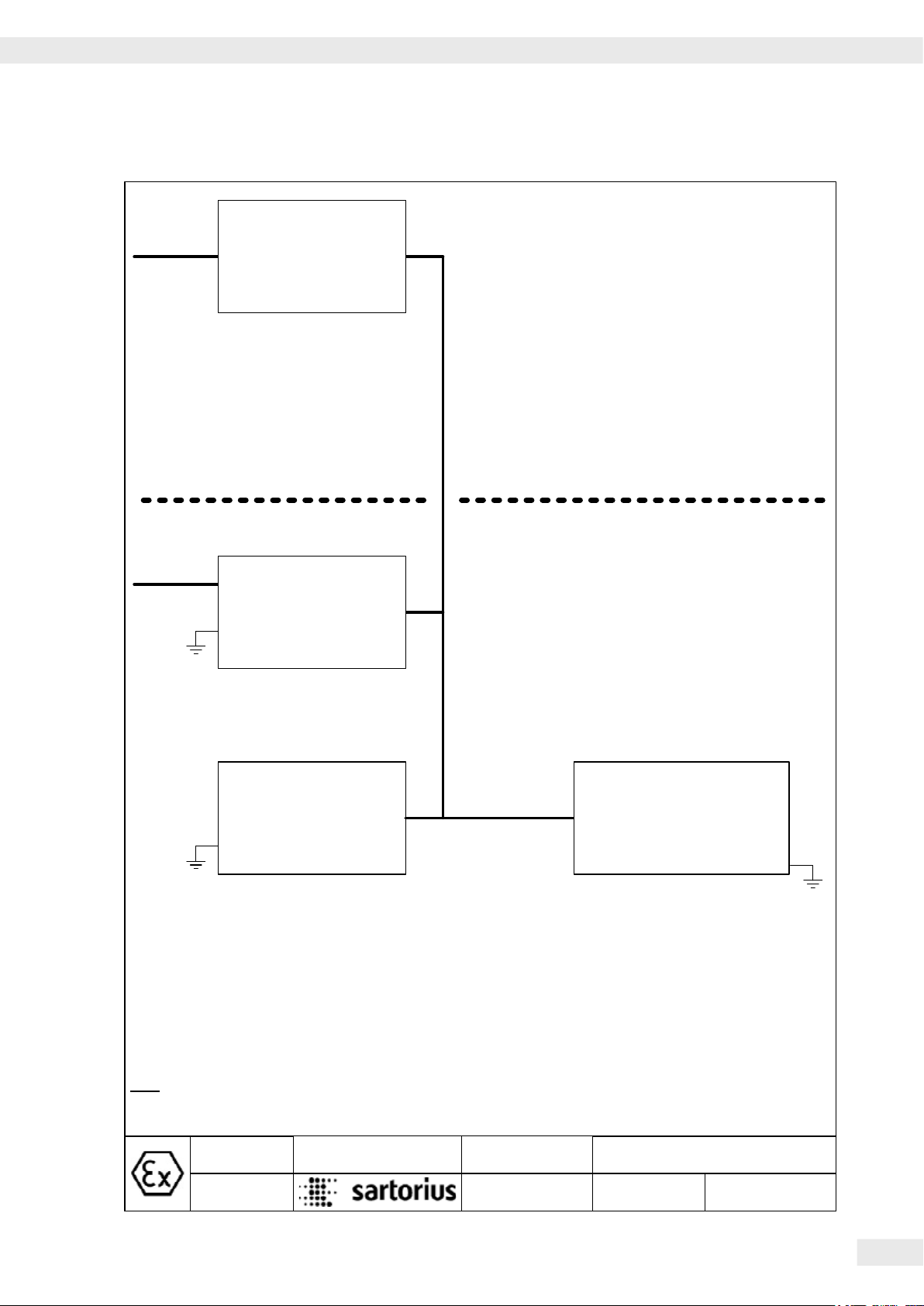
Verification of Intrinsic Safety
Mains cable
Mains cable
1)
Power supply
(100-240 Vac)
II (2) G [EEx ib] IIC
II (1) D
YPS02-Z.R
1)
YPS02-X.R
Power supply
2)
(100-240 Vac)
II 2 G EEx d [ib] IIC T4
II 1 D T135°C IP65
YPS02-X.. /YPS02-Z..:
Circuit Uo Io Po Co Lo
V_1 12.6 V 133 mA 1.46 W 1 µF 300 µH
V_2 12.6 V 133 mA 1.46 W 1 µF 300 µH
V_3 8.6 V 187 mA 1.51 W 4 µF 300 µH
V_4 12.6 V 150 mA 1.68 W 1 µF 300 µH
YRB02-X:
Circuit Uo Io Po Co Lo
V_1 12.6 V 133 mA 1.43 W 0.5 µF 300 µH
V_2 12.6 V 133 mA 1.43 W 0.5 µF 300 µH
V_3 8.6 V 186 mA 1.49 W 0.8 µF 200 µH
V_4 12.6 V 150 mA 1.65 W 0.5 µF 300 µH
Non-Hazardous Area
Hazardous Area
Alternative
connections
Sartorius cable; permanently mounted on the
power supply / explosion-protected (EX)
rechargeable battery pack; cable can be flexibly
installed; max. length: 50m
Zone 1
Gas: IIC T4
YRB02-X
EX battery pack
II 2 G EEx e m [ib]IIC T4
2)
II 1 D IP6X T80°C
Note:
1: For circuits with Vs< 375V
2: Bus bar
Dr. D. Klausgrete
2013-05-02
PMA35001-X..
Alternative
connections
PMA35001-X..
II 2 G Ex ia IIC T4 Gb
2)
Circuit Ui Ii Pi Ci Li
V_1 12.6 V 133 mA 1.46 W 188 nF 0 mH
V_2 12.6 V 133 mA 1.46 W 3 nF 0 mH
V_3 8.6 V 187 mA 1.51 W 391 nF 0 mH
V_4 12.6 V 150 mA 1.68 W 223 nF 82 µH
Power Supply
36953-761-60
Verification of Intrinsic Safety
Revision 00
Page 5of
1
Operating Instructions PMA 35001-X 35

Verification of Intrinsic Safety
Mains cable
1)
2)
II (2) GD [Ex ib] IIC
Any suitable intrinsically
2)
safe Sartorius Equipment
YPSC01-Z
Power supply
(100-240 Vac)
A)
B)
Alternative
connection
YPSC01-X /YPSC01-Z:
Circuit Uo Io Po Co Lo
V_1 12.6 V 115 mA 1.45 W 0.5 µF 350 µH
V_2 12.6 V 115 mA 1.45 W 0.5 µF 350 µH
V_3 8.6 V 168 mA 1.45 W 0.88 µF 350 µH
V_4 12.6 V 134 mA 1.68 W 0.5 µF 350 µH
V_5* 8.6 V 168 mA 1.45 W 0.88 µF 350 µH
*: not used
Sartorius cable; permanently
mounted on the power supply;
cable can be flexibly installed;
max. length: 50m
Non-Hazardous Area
Hazardous Area
Zone 1
Gas: IIC T4
YPSC01-X
B)
Power supply (100-240 Vac)
II 2 G Ex e mb[ib] IIC T4
II 1D (2)G Ex tD A20 [ib]IIC
2)
Note:
1: For circuits with Vs< 375V
2: Bus bar
A: Connection to main printed circuit board (PCB) 1 in YPSC01-.
B: Connection to main PCB 2 in YPSC01-.
IP6X T130°C
Dr. D. Klausgrete
2013-05-02
PMA35001-X..
A)
Alternative
connections
Circuit Ui Ii Pi Ci Li
V_1 12.6 V 133 mA 1.46 W 188 nF 0 mH
V_2 12.6 V 133 mA 1.46 W 3 nF 0 mH
V_3 8.6 V 187 mA 1.51 W 391 nF 0 mH
V_4 12.6 V 150 mA 1.68 W 223 nF 82 µH
Power Supply
36953-761-60
PMA35001-X..
II 2 G Ex ia IIC T4 Gb
Verification of Intrinsic Safety
Revision 00
Page 5of
2
2)
36 Operating Instructions PMA 35001-X

Verification of Intrinsic Safety
YDI05-Z.. interface converter
II (2) GD [EEx ib] IIC or
Z966 Zener barrier
4)
in YDI02-Z..: II (2) G [EEx ib] IIC or
YCO01-Y interface converter
II (2) GD [EEx ib] IIC or
II 3 (2)GD EEx nR[ib]IIC T4
YDI05-Z..
Uo 12.4 V* Ui 12.6 V*
Io 260 mA*** Ii any
Po 800 mW Pi any
Co 1.24 µF* Ci 0
Lo 400 µH* Li 0
Lo/Ro 44 µH/
YCO01-Y
Uo 11.8 V* Ui 12.6 V*
Io 123 mA*** Ii 131 mA
Po 361 mW Pi any
Co 1.5 µF* Ci 0.5 nF
Lo 2 mH* Li 0.8 µH
Lo/Ro 98 µH/
2)
24.8 V** 25.2 V**
112 nF**
400 µH**
* / 22 µH/ **
2)
23.6V** 25.2 V**
129 nF**
2 mH**
* / 98µH/ **
1)
Z966
Uo 12 V*
Io 82 mA /164 mA
Po 0.24 W / 0.48 W
Co 1.41 µF*
Lo 5.52 mH
Lo/Ro 147 µH/
pins A/J/K/N and M
24 V**
125 nF**
57 µH/
8)
8)
1.38 mH
Non-Hazardous Area
Hazardous Area
8)
8)
Zone 1
Gas: IIC T4
RS232 data interface
(pins A/J/K/N and M)
Ui 12.6 V Uo 12.6 V
Ii 85 mA Io 28 mA
Pi 270 mW Po 88 mW
Ci 3 nF Co 1.15 µF
Li 0 Lo 50 mH
FC/FCA/IS.......-.X..
1)
3)
6-wire standard cable, up to 0.5mm² stranded wire, with max.
250nF/km, 750µH/km and minimum 34ohm/km has 22µH/
ohm. However, the length of the cable (flexibly installed) is
limited to under 25m by the RS-232 specifications. 6-wire
cable, type PR6136 (Lmax = 1.1mH/km; Cmax = 220nF/km;
Rmin = 26 ohms/km: 43µH/ohm): under 25m (see above).
scale / weighing
platform
(see remark 5 on page 3)
Note:
1: Per circuit
2: Combined circuits
3: Not all models can be used in zones 20,21,22
4: BAS01ATEX7005; II (1) GD [EEx ia] IIC
5: Both channels connected on Z966
*: Versus GND; **: Between the lines; ***: Resistively limited
Alternative
connection
PMA35001-X..
II 2 G Ex ia IIC T4 Gb
2)
RS232 data interface
Ui 12.6 V* / 25,2V** Uo 10 V* / 20V**
Ii 328 mA*** Io 101 mA***
Pi any Po 253 mW
Ci 2.2 nF* / 0.5nF** Co 3 µF* / 217nF**
Li 0 mH Lo 3 mH
COM1
Lo/Ro 140 µH/
Dr. D. Klausgrete
2013-05-02
PMA35001-X.. RS232 Data Interface
36953-761-60
Operating Instructions PMA 35001-X 37
Verification of Intrinsic Safety
Revision 00
Page 5of
3

Verification of Intrinsic Safety
YDI05-Z.. interface converter
II (2) GD [EEx ib] IIC or
Z966 Zener barrier
4)
in YDI02-Z..: II (2) G [EEx ib] IIC
or
YCO01-Y interface converter
II (2) GD [EEx ib] IIC or
II 3 (2)GD EEx nR[ib]IIC T4
Data cable:
Recommended: Sartorius cable
YCC485-X with approx.
10µH/ohm and 120pF/m (wire/wire)
up to 1000m flexibly installed.
5) 2)
RS485 data interface
Uo 7.2 V Ui 12.6 V
Io 127 mA* Ii 1.5 A*
Po 0.273 W Pi 2.5 W
Co 11.3 µF Ci 0
Lo 2 mH Li 2 µH
Lo/Ro 118 µH/ohm
(UNICOM. LV2)
YDI05-Z..
2) 3)
Uo 12.4 V* Ui 12.6 V*
24.8V** 25.2
V**
Io 130 mA*** Ii any
Po 400 mW Pi any
Co 1.24 µF* Ci 0
112nF**
Lo 0.4 mH* Li 0
0.4 mH**
Lo/Ro 44 µH/
YCO01-Y
* / 22 µH/ **
2)
Uo 7.2 V* Ui 12.6 V*
8.0 V** 25.2 V**
Io 207 mA*** Ii 1.5 A
Po 330 mW Pi 2.5 W
Co 13.5 µF* Ci 1 nF
8.4 µF**
Lo 0.7 mH* Li 1.6 µH
0.7 mH**
Lo/Ro 36 µH/
* / 36µH/ **
Zone 1
Gas: IIC T4
Z9661)pins A/J/K/N and M
Uo 12 V*
24V**
Io 82 mA /164mA
Po 0.24 W / 0.48W
Co 1.41 µF*
125nF**
Lo 5.52 mH
1.38mH
Lo/Ro 147 µH/
57 µH/
Non-Hazardous Area
Hazardous Area
PMA35001-X..
6)
6)
6)
6)
RS485 data interface
8.2 V
3)
4)
Uo 7.2 V
Io 168 mA* Ii 1.5 A*
Po 0.25 W Pi 2.5 W
Co 13 µF
Co 7.6 µF
3)
4)
5) 2)
(LV4)
Ui 12.6 V
Ci 300 nF
Ci 100 nF
Up to 7 additional
CIXS3 or
SIWS… / ISXS...
3)
4)
Lo 0.8 mH Li 0 mH
Lo/Ro 118 µH/ohm
Note:
1: Per circuit
2: Combined circuits
3: Only two RS232 connections are used on the YDI05-Z
4: BAS01ATEX7005; II (1) GD [EEx ia] IIC
5: Data for CIXS3
6: Both channels connected on Z966
*: Versus GND; **: Between the lines; ***: Resistively limited
Dr. D. Klausgrete
2013-05-02
PMA35001-X.. RS485 Data Interface
36953-761-60
II 2 G Ex ia IIC T4 Gb
3)
RS485 data interface
Ui see below Uo 5.2 V
Ii see bwlow Io 210 mA***
Pi any Po 263 mW
Ci 260 nF Co 60 µF
Li 0 mH Lo 600 µH
Ui ±12.4V 12.0V 7.2V
Ii 130 mA*** 164mA*** any
2)
Lo/Ro 125 µH/
Verification of Intrinsic Safety
Revision 00
Page 5of
4
38 Operating Instructions PMA 35001-X

Verification of Intrinsic Safety
YDI05-Z
(Option A25)
Interface converter
II (2) GD [EEx ib] IIC
Alternative
connection
YCO01-Y
Interface converter
RS422 data interface of YDI05-Z
Uo 6.0 V *
Io 172 mA (linear) Ii 0.2 A
Po 0.5 W Pi 2.3 W
Co 12 µF *
Co 17.7 µF
Lo 0.7 mH Li 2 µH
RS422 data interface of YCO01-Y
Uo 7.2 V* Ui 12.6 V*
Io 207 mA*** Ii 1.5 A
Po 330 mW Pi 2.5 W
Co 13.5 µF* Ci 1 nF
Lo 0.7 mH* Li 1.6 µH
Lo/Ro 36 µH/
)
6.8 V **
8.0 V** 25.2 V**
8.4 µF**
0.7 mH**
)
)
**)
*/ 36µH/ *
Ui 12.6 V *
Ci 28 µF *
Ci 200 nF **
2)
25.2 V **
2)
Non-Hazardous Area
)
)
)
)
Cable:
For a standard cable (e.g., type
LiYCY with max. 250nF/km (wire
versus wire or wire versus
shield), max. 750µH/km and at
least 34 ohms/km (e.g. 0.5mm²
stranded wire), this yields Lo/Ro
= 22 µH/ohm
the flexibly installed cable: 330m
RS422 data interface
Uo 5,2 V Ui 8.6 V
Io 290 mA Ii 210 mA
Po 496 mW Pi 0.5 W
Co 60 µF Ci 0.5 µF
Lo 300 µH Li 0 mH
Lo/Ro 50 µH/
Note:
1: Per circuit
2: Combined circuits
*: Versus GND; **: Between the lines; ***: Resistively limited
Permitted length of
2)
(COM1)
Hazardous Area
Zone 1
Gas: IIC T4
PMA35001-X..
II 2 G Ex ia IIC T4 Gb
Dr. D. Klausgrete
2013-05-02
PMA35001-X.. RS422 Data Interface
36953-761-60
Operating Instructions PMA 35001-X 39
Verification of Intrinsic Safety
Revision 00
Page 5of
5

Certificate of Compliance
40 Operating Instructions PMA 35001-X

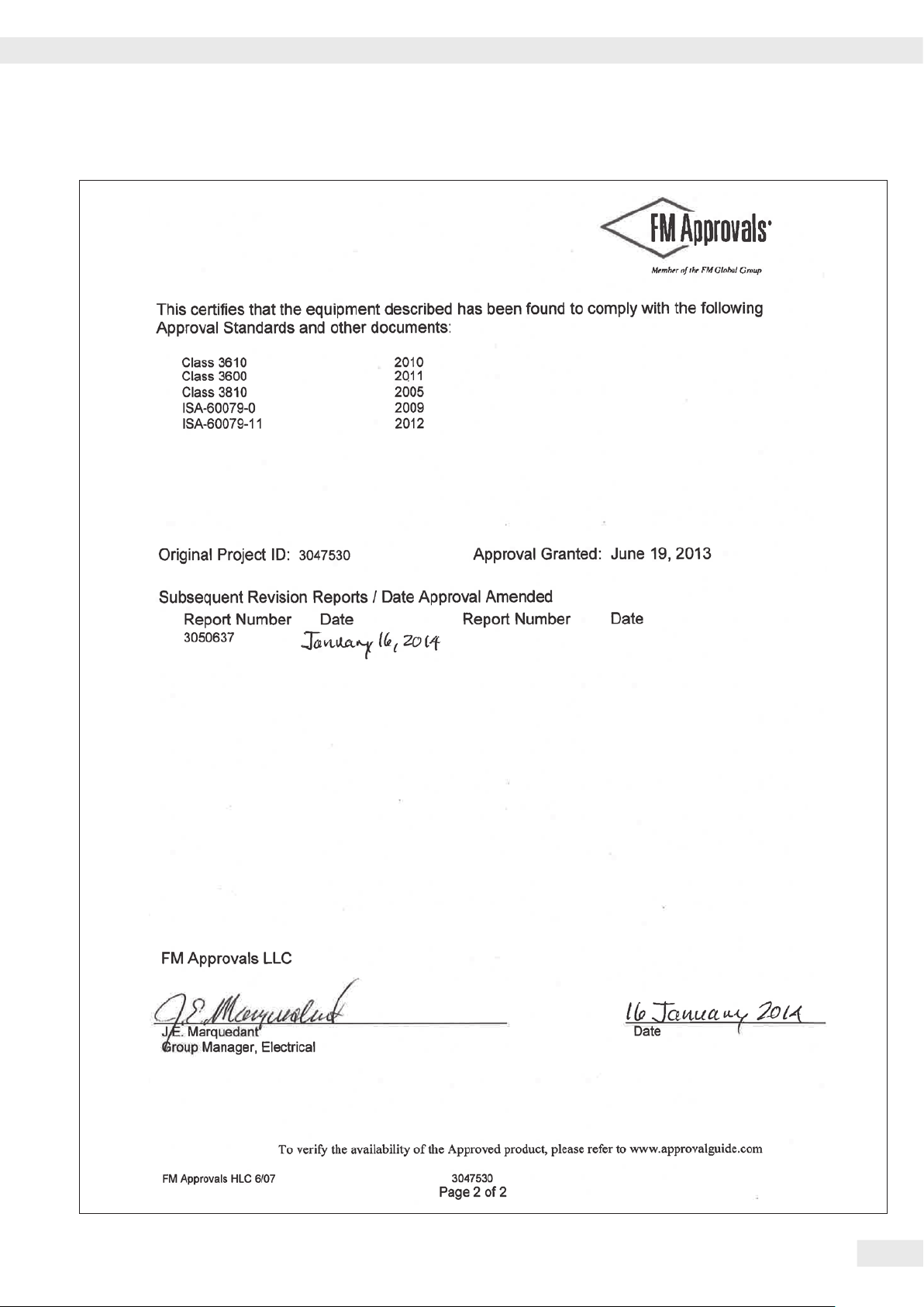
Certificate of Compliance
Operating Instructions PMA 35001-X 41
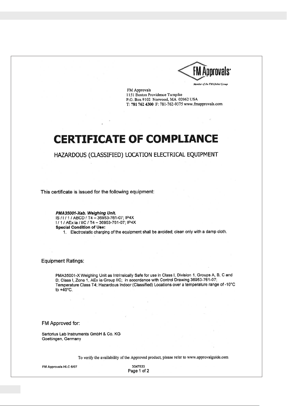
Certificate of Compliance
42 Operating Instructions PMA 35001-X
Certificate of Compliance
Operating Instructions PMA 35001-X 43

Last updated:
The information and figures contained in these
instructions correspond to the version date
specified below.
Sartorius reserves the right to make changes
to the technology, features, specifications and
design of the equipment without notice.
Masculine or feminine forms are used to
facilitate legibility in these instructions and
always simultaneously denote the other
gender as well.
Copyright notice:
This instruction manual, including all of its
components, is protected by copyright.
Any use beyond the limits of the copyright law
is not permitted without our approval.
This applies in particular to reprinting,
translation and editing irrespective of the type
of media used.
© Sartorius Germany
Sartorius Lab Instruments GmbH & Co. KG
Otto-Brenner-Strasse 20
37079 Goettingen, Germany
Phone:
+49.551.308.0
Fax:
www.sartorius.com
+49.551.308.3289
04 | 2016
Printed in the EU on paper bleached
without chlorine. | W
Publication No.: WPM6074-e160403
 Loading...