


Installation Instructions | Installationsanleitung | Notice d’installation |
Instrucciones de instalación | Installationsanvisning
PMA.Evolution | PMA.HD
EVO1X | LAB1X
Paint-mixing Scales for Use in Potentially Explosive Atmospheres |
Farbmischwaagen für den Einsatz in explosionsgefährdeten Bereichen |
Balances pour peintures pour une utilisation dans des atmosphères explosives |
Balanzas para la mezcla de pinturas para el uso en áreas potencialmente explosivas |
Färgtillblandningsvågar för användning i explosionsfarliga områden
1000025351

Contents of DVD:
− Operating instructions as a pdf file in various
international languages
− Adobe Reader
− Software drivers for configuration of USB interfaces
English – page 3
In cases involving questions of interpretation,
the German-language version shall prevail.
Deutsch – Seite 13
Im Auslegungsfall ist die deutsche Sprache maßgeblich.
Download online: www.sartorius.com/paintmixing
System Requirements:
– Windows, MacOS X
– Browser with JavaScript enabled
– PDF-Reader
Use start.html to run the application
Français – page 23
En cas de questions concernant l’interprétation,
la version en langue allemande fera autorité.
Español – página 33
En caso de interpretación, la versión en lengua
alemana será determinante.
Svenska – sidan
I oklara fall är den tyska tolkningen avgörande.
43

English
Contents
1 About This Document .............................3
1.1 Scope........................................3
1.2 Symbols Used .................................3
2 Safety ...........................................3
2.1 Intended Use..................................3
2.2 Explosion Protection ...........................4
2.3 Personnel Qualification.........................4
2.4 Significance of these Instructions ................5
2.5 Proper Working Order of the Device ..............5
2.6 Work on the Electrical Equipment of the Device ....5
2.7 Personal Protective Equipment ..................5
2.8 Safety Instructions Concerning Operation
of the Device .................................5
3 Installation.......................................5
3.1 Scope of Delivery..............................5
3.2 Unpacking....................................5
3.3 Selecting a Setup Location......................5
3.4 Installing the Scale ............................6
3.5 Connecting the Grounding Cable.................6
3.6 Establishing the Power Supply...................7
3.7 Anti-theft Locking Device.......................8
3.8 Leveling......................................8
3.9 Warm-up Time ................................9
4 Cleaning and Maintenance.........................9
4.1 Cleaning .....................................9
4.2 Servicing .....................................9
5 Disposal..........................................9
5.1 Information on Decontamination ................9
6 Accessories......................................10
7 Serial Number Coding ............................10
1.2.1 Warnings
WARNING
Denotes a danger with risk that death or severe injury may
result if it is not avoided.
CAUTION
Denotes a danger with risk that moderate or minor injury may
result if it is not avoided.
NOTICE
Denotes a danger that can result in property damage if the
risk is not avoided.
1.2.2 Other Symbols
t
y
[ ] Text inside brackets refers to control and display
Figures on the Operating Display
The figures in these instructions are based on “standard”
scales. On verified scales, some displays and reports may
deviate slightly from the figures. Where this is significant
for operation, the differences will be explained in the text.
Required action: Describes actions which must be
carried out.
Result: Describes the result of the activities
carried out.
elements.
This symbol provides information for the sale of
scales verified for use in legal metrology.
In the following, the term “verified” is used to
mean “verified for use in legal metrology” or
“conformity-assessed.”
8 Technical Data...................................11
8.1 General Data.................................11
8.2 Model-specific Data...........................12
8.3 Verified Models with EC Type Approval Certificate:
Model-specific Technical Data ..................12
9 EU Declaration of Conformity .....................12
1 About This Document
1.1 Scope
This operating manual applies to paint-mixing scale models:
− EVO1X
− LAB1X
1.2 Symbols Used
The term “device” used in these instructions always refers to
the combined unit of scale, AC adapter and ex-link converter.
2 Safety
2.1 Intended Use
This scale is only intended for mixing colors and paints.
Appropriate containers must be used for loading each type
of material.
The scale can be operated via the display as a stand-alone
device or using application software (e.g., a paint-mixing
program from a paint manufacturer) installed on a connected
PC. The PC is connected to the ex-link converter via a USB
cable. Follow and observe the explosion protection
instructions in Chapter 2.2, page 4.
These instructions are part of the device. The device is
intended exclusively for use in accordance with these
instructions.
EVO1X | LAB1X Installation Instructions 3

Any further use beyond this is considered improper. If the
device is not used properly: The protective systems of the
device may be impaired. This can lead to unforeseeable
personal injury or property damage.
In the event of use in systems and under ambient conditions
with higher safety requirements, you must observe the
requirements and provisions applicable in your country.
Operating Conditions for the Device
The device may only be used indoors.
The device may only be used with the equipment and under
the operating conditions described in the Technical Data
section of these instructions.
You may not modify the device or make any technical
changes on your own. Any retrofitting or technical changes
to the device are only permitted with prior written permission
by Sartorius.
Do not expose the device or accessories supplied by Sartorius
to extreme temperatures, aggressive chemical vapors,
moisture, shock, vibrations or strong electromagnetic fields.
Observe the conditions of operation described in the Technical
Data section.
The casing on all connection cables between the devices as
well as on the wires inside the device housing are made of
PVC. Chemicals that corrode this material must be kept away
from these cables.
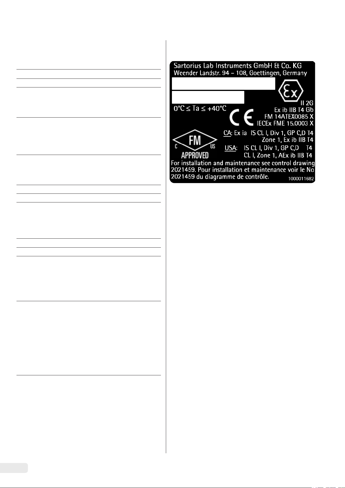
2.2 Explosion Protection
Use within the scope of validity of the European ATEX
Directive:
− In accordance with Directive 2014/34/EU, the model in the
EVO1X | LAB1X series is a category 2 device, suitable for
use in Zone 1 potentially explosive areas.
− The ex-link converter YCO14-Z is only suitable for
installation as an associated electrical apparatus outside
of the potentially explosive area.
− The ex-link converter YCO14-Y is an associated electrical
apparatus that can be used in Zone 2.
− Refer to the EC Type Examination Certificates from
Page 53 for the device ID codes. Please observe the
safety instructions in drawing 2023040 from Page 53.
2.3 Personnel Qualification
These instructions are addressed to the target groups below
mentioned. All persons working on the device must possess
the stated knowledge and authorizations.
If no qualifications are indicated for the actions described in
these instructions: The actions described are addressed to the
“User” target group.
If individual actions must be carried out by other target
groups or by Sartorius Service personnel: The qualification
required will be indicated in the description of the action.
Target group Knowledge/responsibilities
User The user is familiar with the operation of the
device and the associated work processes.
The user understands the hazards which may
arise when working with the device and can
avoid these hazards.
The user has been trained in the operation of
the device. Training takes place within the
scope of startup and is carried out by the
operating engineer/laboratory manager or
the operator of the device.
Operating
engineer/
laboratory
manager
Electrician A qualified electrician has the specialized
Operator The operator of the device is responsible for
The operating engineer/laboratory manager
makes decisions about the use and
configuration of the device.
The operating engineer/laboratory manager
has been trained in the operation of the
device. Training takes place within the scope
of startup and is carried out by Sartorius
Service or the operator.
training, knowledge, and experience as well
as familiarity with applicable standards and
regulations to evaluate the assigned work
and identify possible hazards.
compliance with safety requirements and
workplace safety regulations.
The operator must ensure that all persons
who work on the device have access to the
relevant information and have been
instructed in work on the device.
Use in Canada and the USA:
The intrinsically safe scales in the EVO1X | LAB1X model series
are suitable for use in Class I, Division 1 and Class I, Zone 1.
The ex-link converter YCO14-Y can be used in Class I, Division
2 and Class I, Zone 2.
Please observe Certificates of Conformity FM16US0226X
and FM16CA0124X as well as Control Drawing 2021459 from
Page 53.
Use in Australia/New Zealand:
Please observe IECEx Certificate of Conformity IECEx FME
14.0008X and Safety Instructions 2023040 from Page 53.
4 EVO1X | LAB1X Installation Instructions
English
2.4 Significance of these Instructions
Failure to follow the instructions in this manual can have
serious consequences, e.g., exposure of individuals to
electrical, mechanical, or chemical hazards.
t Before working with the device: Read the instructions
carefully and completely.
t If these instructions are lost: Request a replacement or
download the latest version from the Sartorius website
(www.sartorius.com).
t The information contained in these instructions must be
available to all individuals working on the device.
2.5 Proper Working Order of the Device
A damaged device can cause malfunctions or lead to hard-todetect hazards.
t Only operate the device when it is safe and in perfect
working order.
t Immediately disconnect the damaged device from the
power.
t Have any malfunctions or damage repaired immediately
by the Sartorius Service.
2.6 Work on the Electrical Equipment of the Device
Work on and modifications to the electrical equipment of the
device may only be carried out by Sartorius Service personnel.
The device may only be opened by Sartorius Service personnel.
Seal on Scales Verified for Use in Legal
Metrology
Legislation requires that a seal be affixed to
verified scales. On Sartorius devices, this seal takes
the form of a sticker with the “Sartorius” logo.
If the seal is removed, the validity of verification
will become void and you must have your scale
re-verified. The verification supplied here is for
verified weighing instruments for use in the EEA.
Please keep it in a safe place.
2.7 Personal Protective Equipment
Personal protective equipment to protect against risks arising
from the material being processed.
t When the workplace or the process, in which the device
is used, requires personal protective equipment: Wear
personal protective equipment.
− The surface of the operating display should not be touched
with pointed, sharp, hard, or rough objects. You should
only use the touch pen provided or your fingertips. Do not
use parts of clothing (e.g., sleeves) or sponges for cleaning
because these can scratch the surface (e.g., due to rivets or
buttons in the sleeve or sand in the sponge).
− Avoid generating static electricity on the glass panel of
the operating display and plastic casing.
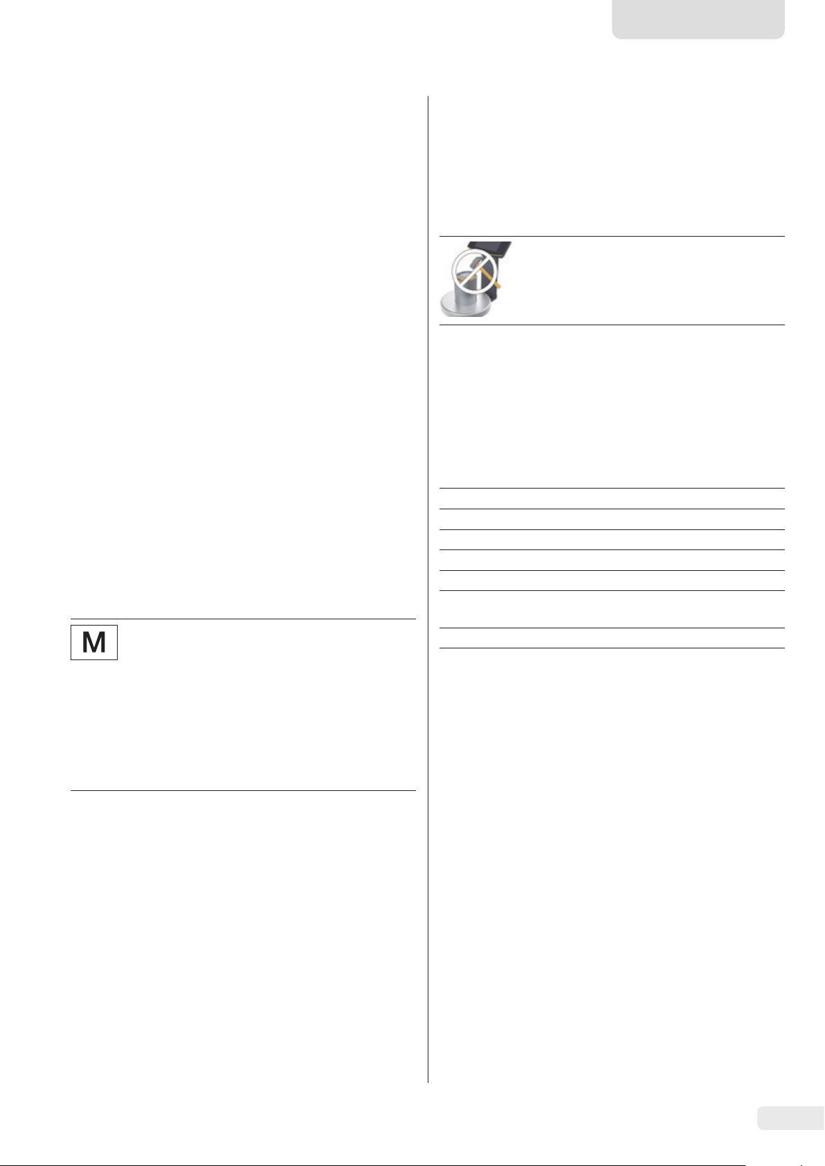
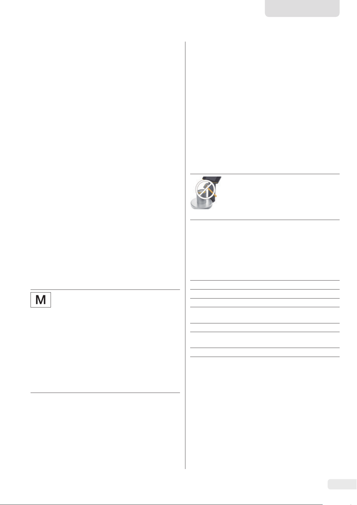
Danger of Damage to the Scale!
Never close a paint can using a hammer while
it is still on the weighing pan.
When closing, place the paint can on a firm,
stable surface.
3 Installation
3.1 Scope of Delivery
Model PMA.Evolution PMA.HD
Large weighing pan: d 233 mm
Small weighing pan: d 180 mm
USB cable x x
Ex-link converter x x
Potential equalization cable x x
Link cable from converter to
scale
Installation instructions x x
3.2 Unpacking
Procedure
t Open the packaging, making sure to remove all parts
carefully.
t After unpacking the device, check it immediately for any
external damage.
t If the device is stored temporarily: Store the device
according to the ambient conditions (ambient conditions
see Chapter “8.1 General Data”, page 11).
t Save the box and all parts of the packaging for any future
transport. All cables should be unplugged when
transporting.
3.3 Selecting a Setup Location
x –
– x
x x
2.8 Safety Instructions Concerning Operation of the Device
− Take care that the glass panel of the operating display is
not damaged (e.g., by falling objects, impact, or extreme
pressure). If the glass panel is damaged, disconnect the
device from the power supply immediately.
Select the right setup location:
− Set up the device on a stable, even surface that is not
exposed to vibrations.
− Maintain free access to the device at all times.
− The devices must be handled carefully according to the
IP protection rating. The environment must be suitably
secured.
EVO1X | LAB1X Installation Instructions 5
− In the event of use in systems and under ambient
conditions with higher safety requirements, you must
observe the requirements and provisions applicable in
your country.
Choose a location that is not subject to the following negative
influences:
− Heat (heater or direct sunlight)
− Drafts from open windows, AC systems, and doors
− Extreme vibrations during weighing
− Heavy traffic areas (personnel)
− Extremely high humidity
− Electromagnetic fields
− Extremely dry air
Acclimatization
Condensation from humidity can form on the surfaces of a
cold device when it is brought into a warm area. You should
therefore let a device that has been disconnected from its
power source acclimatize for approximately 2 hours before
reconnecting it to the supply voltage.
3.4 Installing the Scale
NOTICE
The device must be disconnected from the power supply for
all assembly work.
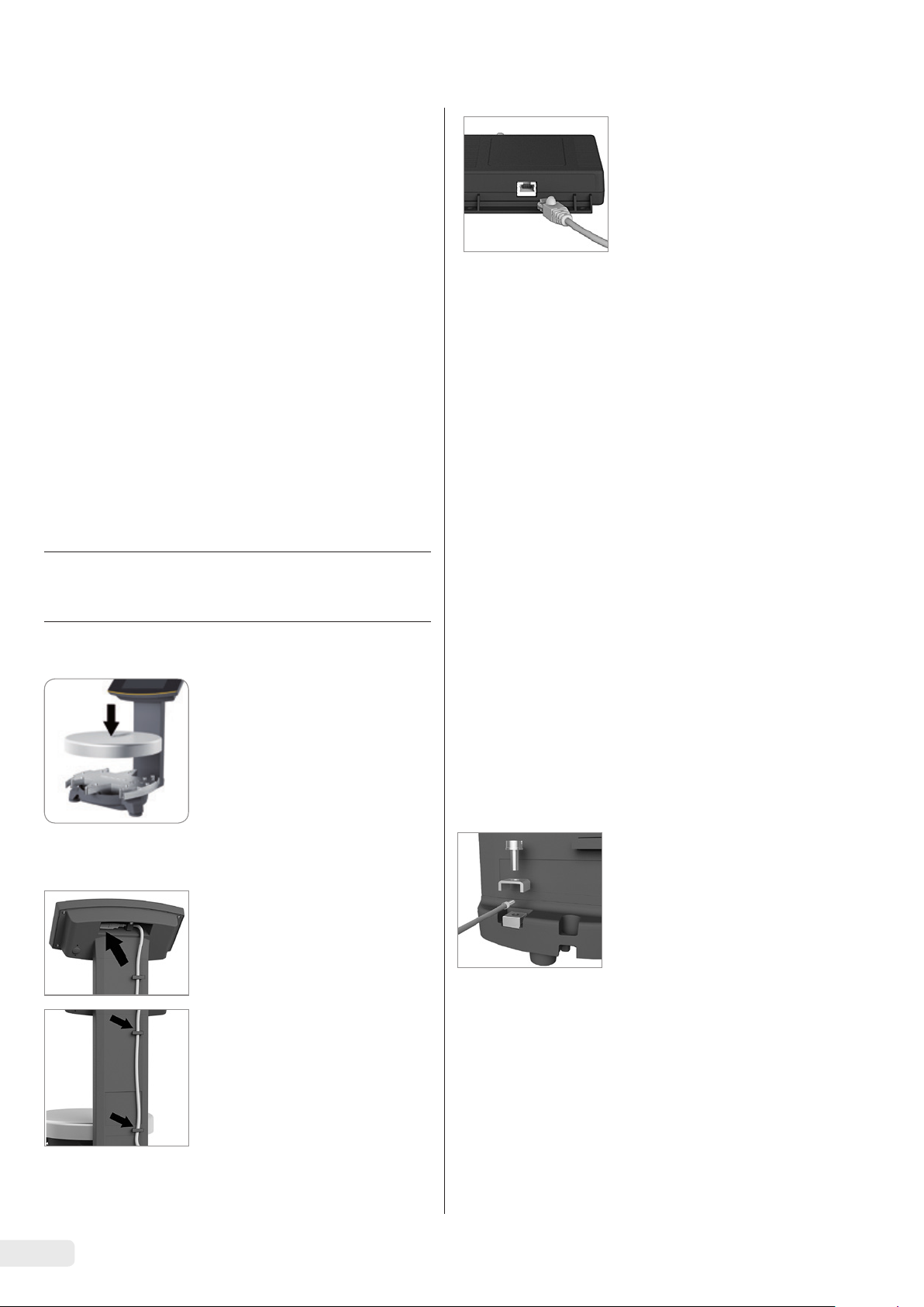
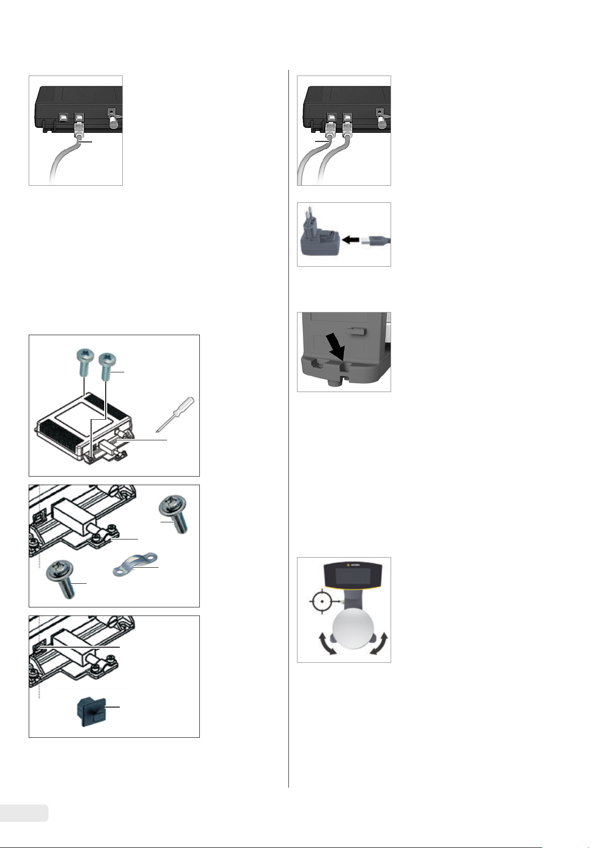
3.4.1 Place the weighing pan on the scale
t Place the weighing pan onto the
scale from above.
t Connect the link cable to the
ex-link converter.
3.5 Connecting the Grounding Cable
Required qualification: Electrician
This explosion-protected system should be set up according
to commonly accepted technical standards. The applicable
national electrical code and safety regulations for your
particular country must be observed.
Before commissioning the scale, a check must be carried out
by or under the supervision of a qualified electrician to ensure
that the system is in good working order.
Check whether or not the competent authorities (e.g.,
industrial supervisory board) need to be informed. It is also
necessary to carry out inspections of the system during
operation.
Inspection intervals should be such that any significant
defects that may occur can be identified in good time.
Inspections should be carried out at least once every three
years. The applicable requirements and guidelines should
also be observed during operation.
The system should only be operated for the first time when
it is certain that the area is not potentially explosive.
If deviations are evident during startup due to transport
damage (e.g., no display, no backlighting), disconnect the
scale from the power supply and contact the Sartorius Service
Center.
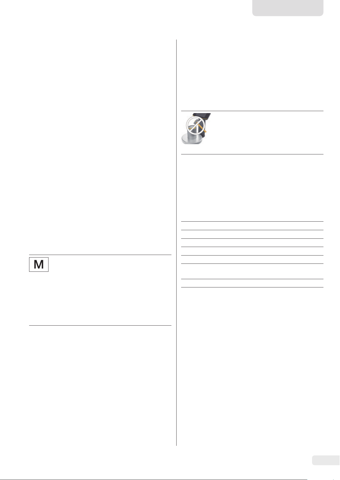
3.4.2 Connecting the Scale
t Insert the link cable plug into
t Lay the link cable (blue) through
the RJ-45 socket on the back of
the display.
the cable holders on the back of
the scale.
Installation must be carried out properly by a trained
electrician and according to commonly accepted technical
standards.
Connect the scale to the equipotential bonding conductor using
an equipotential bonding cable
with a gauge of at least 4 mm².
t Connect the cable lug of the
equipotential bonding cable to
the grounding terminal of the
scale.
t Connect the equipotential
bonding cable to the customer-supplied equipotential
bonding conductor.
6 EVO1X | LAB1X Installation Instructions
Connect the ex-link converter to
the equipotential bonding conductor using another equipotential
bonding cable with a gauge of at
least 4 mm².
t Connect the cable lug of the
equipotential bonding cable to
the grounding terminal of the
ex-link converter.
t Connect the equipotential
bonding cable to the customer-supplied equipotential
bonding conductor.
English
3.6 Establishing the Power Supply
Required qualification: Electrician
The scale is connected to the power supply via a PC/
notebook or using the optional AC adapter YPS06-USB
(see Chapter “6 Accessories”, page 10), which is supplied with
mains adapters for use in various countries.
NOTICE
− Ensure that the voltage rating printed on the AC adapter
is identical to your local mains voltage (connection data
see Chapter “8.1 General Data,” page 11).
− If the stated supply voltage or the plug design of the AC
adapter does not comply with your country's standard,
please inform your nearest Sartorius representative.
Power supply via the AC adapter is only required:
− When no PC or notebook is available.
− In exceptional cases, when the output voltage of the
USB interface of the PC or notebook is not sufficient.
AC adapter assembly is described in the following.
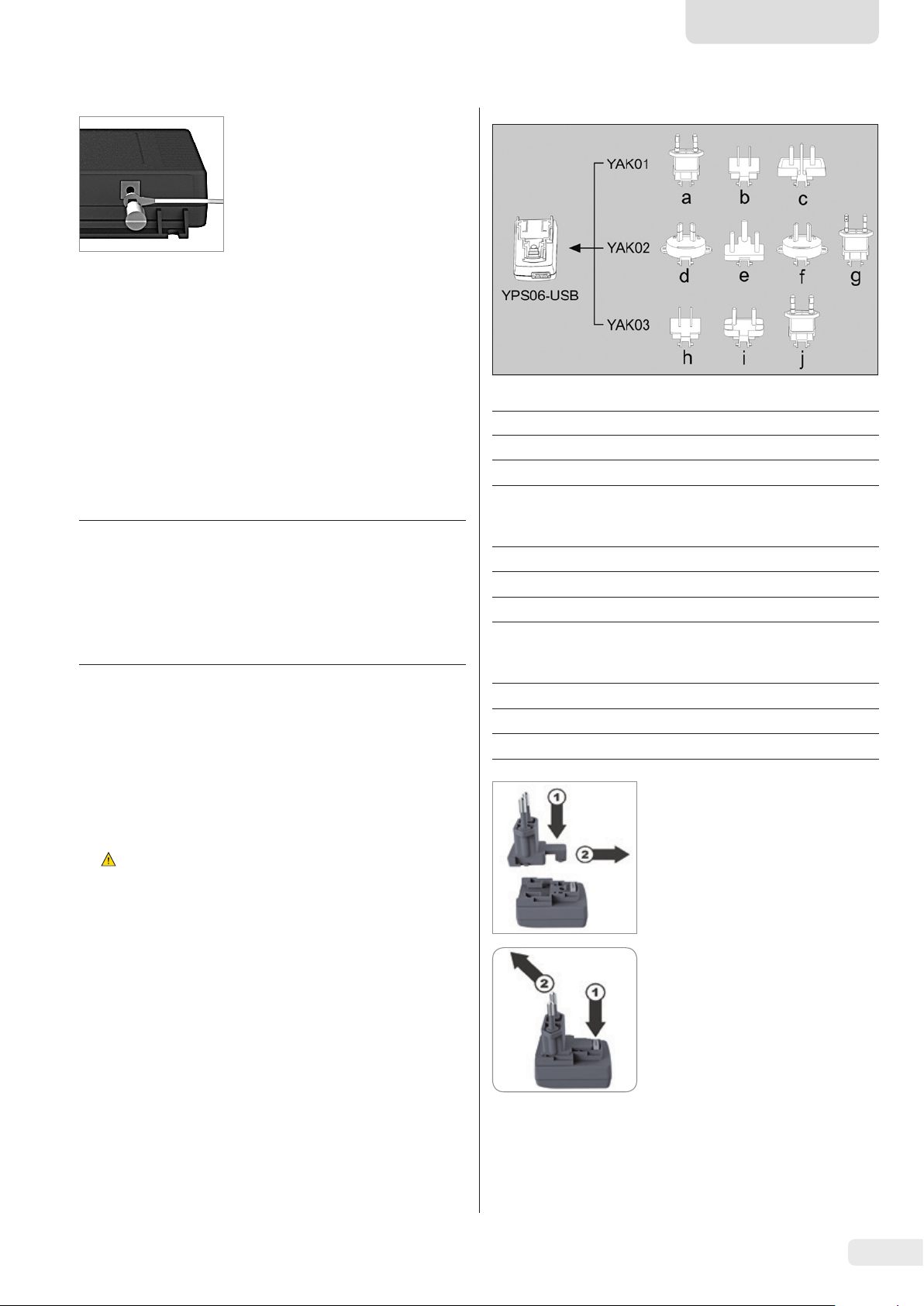
3.6.1 Installing AC Adapter
WARNING Lethal electric shock and equipment
t
damage due to incorrect power plug adapter! Only use
the country-specific power plug adapter. Never plug
the power plug adapter into the socket when it is
disconnected from the AC adapter.
t Use the right mains adapter for your mains power supply:
Mains adapter set YAK01
Bag Region/Country
a) transparent Europe/EU (except United Kingdom)
b) blue USA
c) yellow United Kingdom
Mains adapter set YAK02
d) red Australia
e) turquoise South Africa
f) white Argentina
g) pink Brazil
Mains adapter set YAK03
h) light brown China
i) black India
j) green Korea
t Push (1) and slide (2) the mains
adapter required for your power
supply into the opening of the
AC adapter module.
When doing this, the mains
adapter needs to lock into
position.
Removing/Replacing the Mains
Adapter
t Unlock (1) and then remove (2)
the mains adapter.
EVO1X | LAB1X Installation Instructions 7
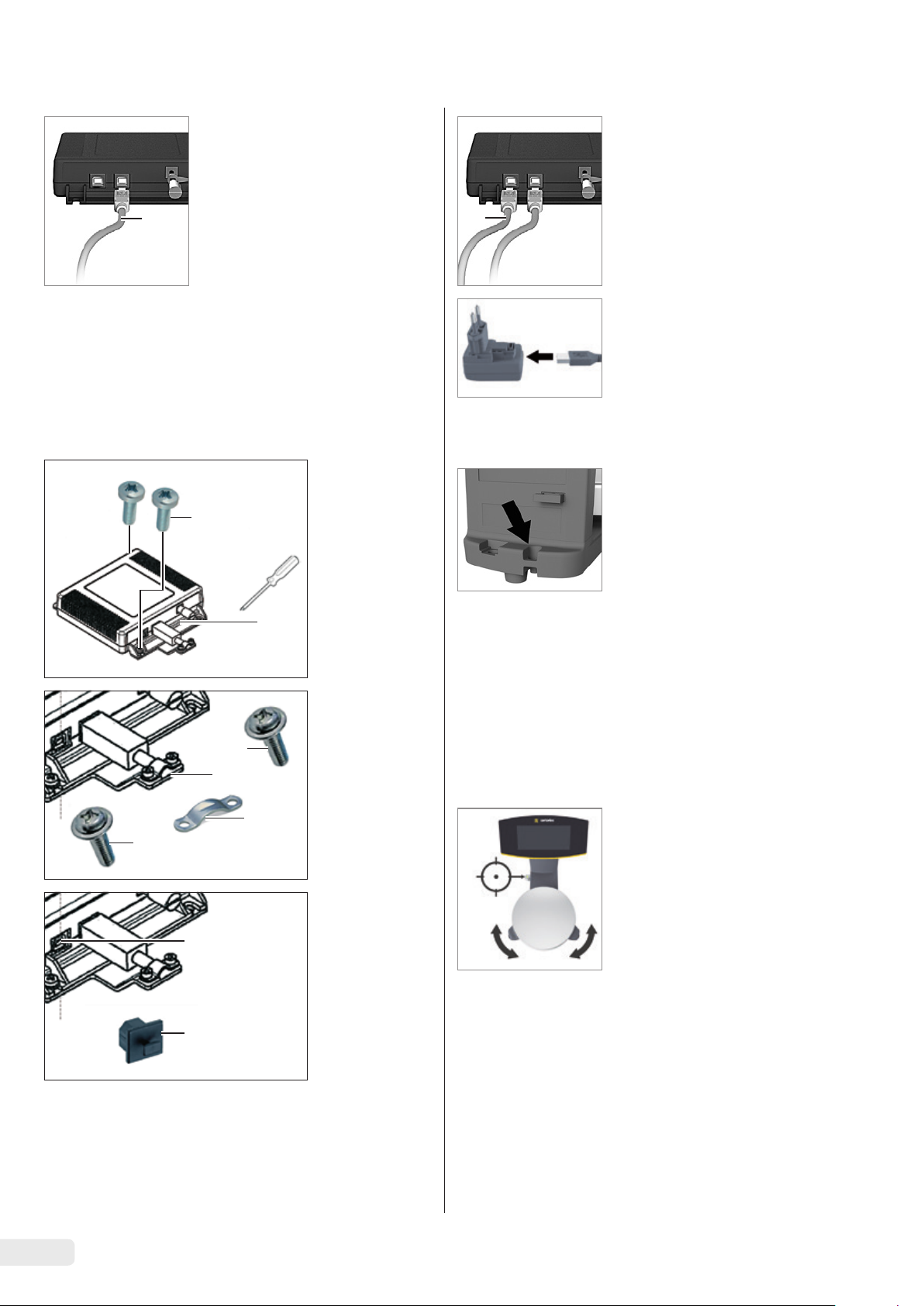
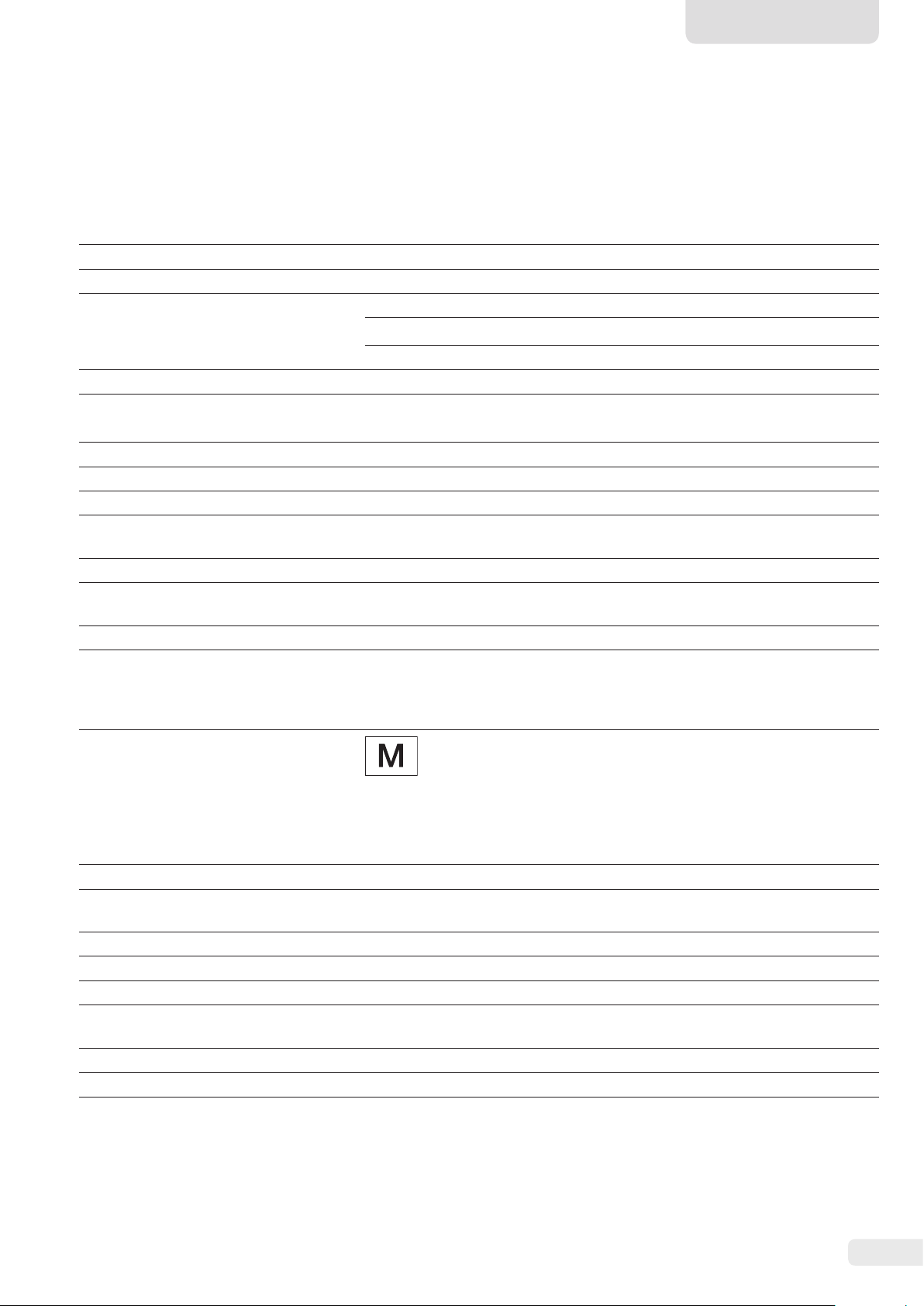
Connecting a PC/Notebook
t Insert a USB cable (1) into
the right-hand socket on the
ex-link converter and connect
the cable to a PC or notebook.
1
If the ex-link converter
2
YCO14-Y is being used and
installed in Zone 2 or Division 2
potentially explosive areas and
the USB cable (1) does
not have an intrinsically safe
electrical circuit, the cable
Connecting the AC Adapter
(Optional); not for YCO14-Y
when Installed in Zone 2 or
Division 2 Potentially Explosive
Areas
t Insert an additional USB cable
(2) into the ex-link converter.
t Insert the USB cable into the
YPS06-USB AC adapter.
t Plug the AC adapter into a wall
outlet (supply voltage).
must be secured against
disconnection. Refer to the
Control Drawing 2021459 and
Safety Instructions 2023040
from Page 53 as well as the
following illustrations.
t Fasten the
strain relief
YSR01 to the
2
2
converter (1)
using the two
3.7 Anti-theft Locking Device
t If required, secure the scale at
the back.
screws (2).
1
3.8 Leveling
Leveling for PMA.HD and Verified Models
t Attach the
USB cable to
the strain
2
3
relief (1)
using the
clamp (3)
1
and the two
screws (4).
2
t Use the
protective
5
cap (6) to
seal up the
left-hand
USB port (5).
6
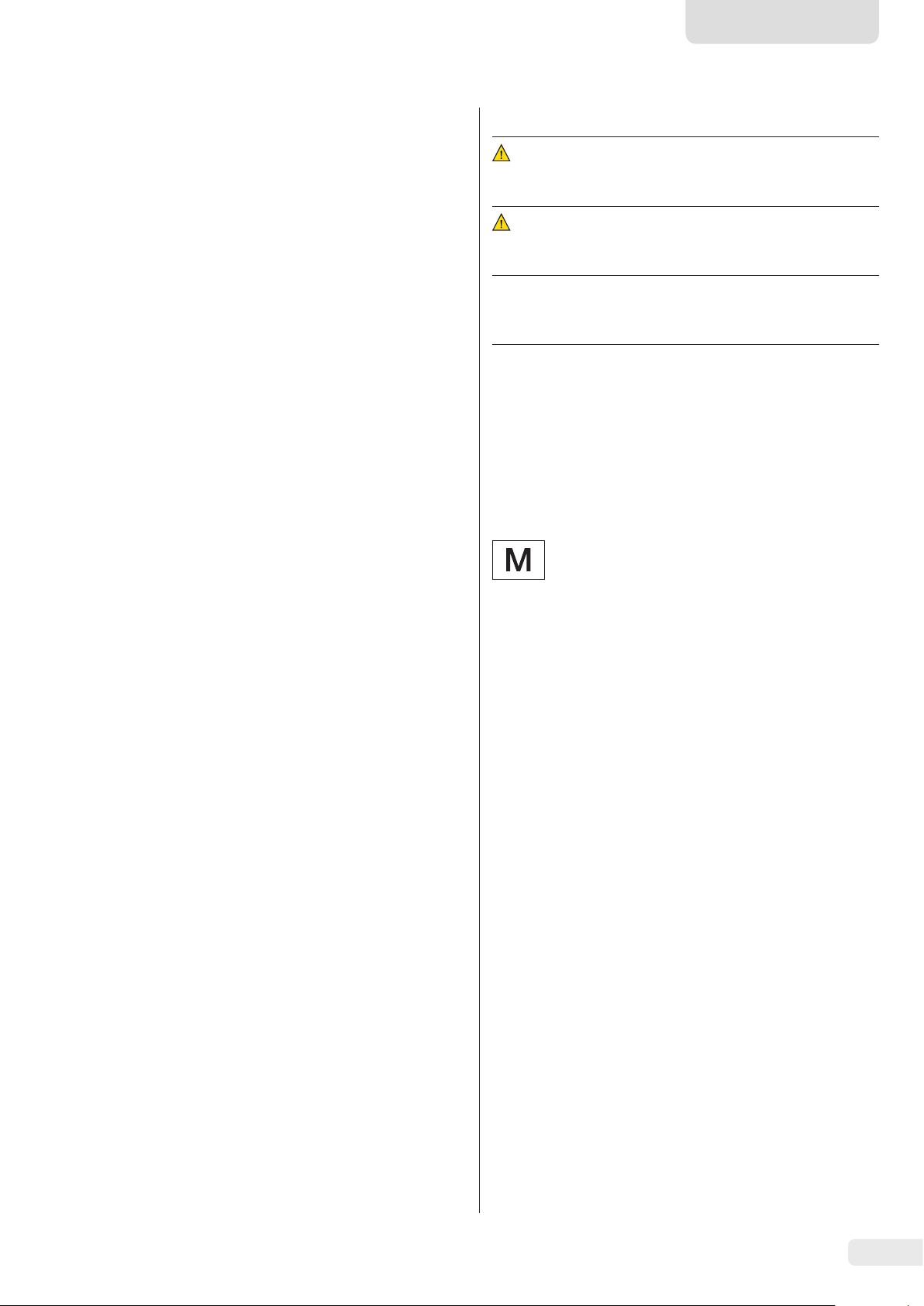
Leveling the scale compensates for slant or unevenness at the
place of installation. The scale must be perfectly horizontal to
ensure consistent, reproducible weighing results.
The scale needs to be re-leveled and then adjusted if
necessary each time its setup location is changed.
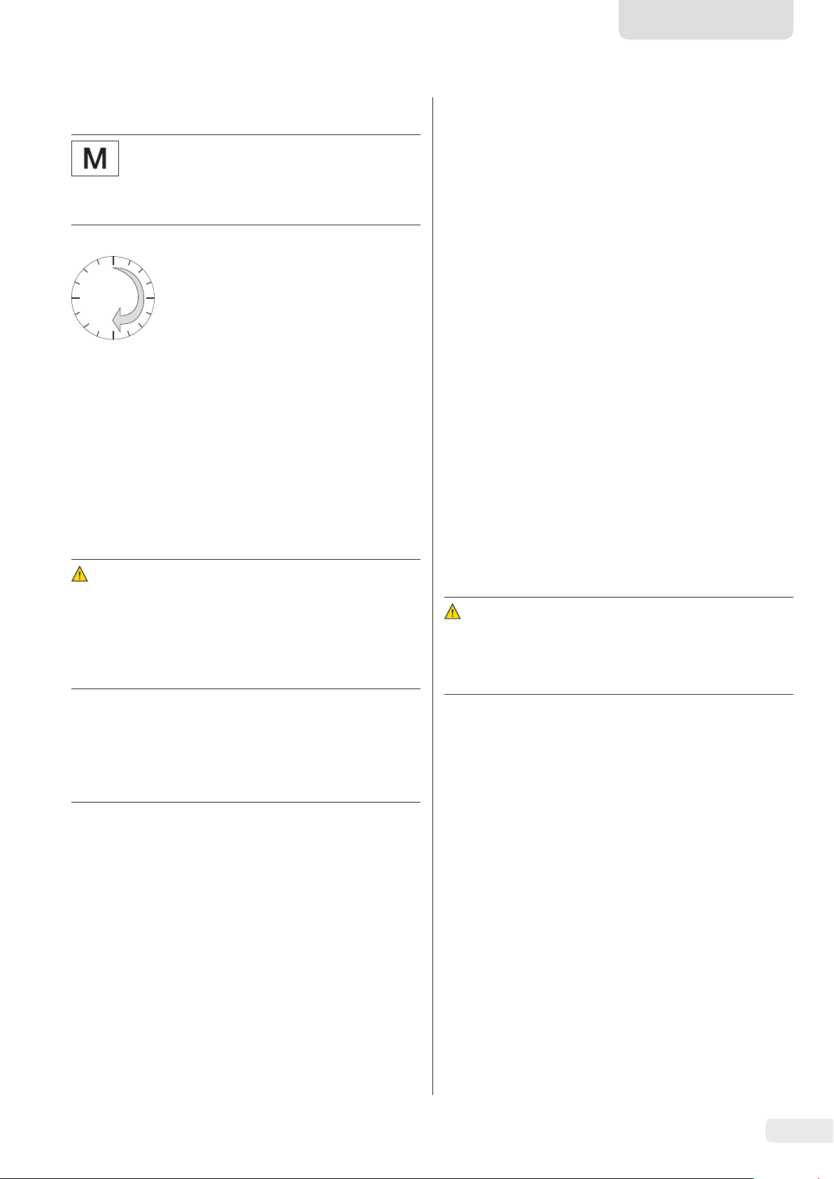
t Turn the two leveling feet as
shown in the illustration until
12*
9*
the air bubble is centered within
the circle of the level indicator.
− Air bubble at “12 o'clock:” Turn
6*
both feet clockwise.
− Air bubble at “3 o'clock:” Turn
the left foot clockwise and the
* o'clock
right foot counterclockwise.
− Air bubble at “6 o'clock:” Turn
both feet counterclockwise.
− Air bubble at “9 o'clock:” Turn
the left foot counterclockwise
and the right foot clockwise.
8 EVO1X | LAB1X Installation Instructions
0
30
English
3.9 Warm-up Time
Using a Scale Verified for Use in Legal
Metrology:
Ensure that there is a warm-up time of at least
24 hours after initial connection to the power
supply.
To ensure accurate results are delivered,
the scale must warm up for at least
30 minutes after initial connection to
the power supply.
Only then will the device have reached the
required operating temperature.
4 Cleaning and
Maintenance
4.1 Cleaning
Before cleaning the AC adapter, ex-link converter, or the
scale: Disconnect all devices from the power supply.
WARNING Electrical Hazard from Voltage or
Current
Disconnect the AC adapter (if connected) from the mains.
Unplug any connected data cables from the ex-link converter.
Never open the scale or the AC adapter. The parts contained
in these cannot be cleaned, repaired or replaced by the
operator.
Cleaning the Device Housing
t Wipe off the housing with a slightly damp cloth. For more
severe contamination, use a mild soap solution.
t Wipe the device with a soft cloth.
4.2 Servicing
To ensure the continued accuracy of your scale, we
recommend scheduling regular servicing at least once a year.
Sartorius Service offers different service contracts with
maintenance intervals that are tailored to your needs.
A calibration certificate should always be issued as part
of every maintenance session. Safety inspections of the
AC adapter and its connections must be performed at
appropriate intervals by a qualified electrician (e.g. every
2 years).
5 Disposal
5.1 Information on Decontamination
According to the EU directives [European directive on
hazardous substances], the owners of devices that come
into contact with hazardous substances are responsible for
properly disposing of these devices and for declaring such
devices when transporting them.
WARNING
Risk of injury due to contaminated devices!
Devices contaminated with hazardous materials (NBC contamination) will not be accepted for repair or disposal.
NOTICE
Do not clean the following parts with acetone or aggressive
cleaning agents:
− Mains socket
− Data interface
− Labels, and all other plastic parts
Procedure
t Disconnect the device from the power supply.
t NOTICE Make sure that no liquid or dust gets into the
scale or the AC adapter.
t NOTICE Corrosion or damage to the device due to
unsuitable cleaning agents!
t Do not use corrosive, chloride-containing and
aggressive cleaning agents.
t Do not use cleaning agents that contain abrasive
ingredients, e.g. scouring agents, steel wool.
t Only use soft brushes and cloths for cleaning.
t Do not use solvent-based cleaning agents.
Cleaning the Control Panel
t Before cleaning the control panel: Turn off the device as
touching the screen could trigger unwanted inputs.
5.1.1 Information on Disposal
The device and its accessories do not belong in your regular
household waste, since they are made of high-grade materials
which can be recycled and reused. All parts must be disposed
of properly by disposal facilities.
The packaging is made of environmentally friendly materials
that can be used as secondary raw materials.
5.1.2 Disposal
Requirements
The device has been decontaminated.
Procedure
t Dispose of the device. Follow the disposal instructions on
our website (www.sartorius.com).
t Dispose of the packaging in accordance with local
government regulations.
EVO1X | LAB1X Installation Instructions 9
6 Accessories
Accessories Order Number
AC adapter (5 V/900 mA) YPS06-USB
USB cable, 5 m
AC plug adapter set for YPS06-USB YAK01
− USA and Japan
− Europe/EU
− United Kingdom
AC plug adapter set for YPS06-USB YAK02
− Australia
− South Africa
− Argentina
− Brazil
AC plug adapter set for YPS06-USB YAK03
− India
− Korea
− China
Ex-link converter
Ex-link converter
Link cable
from converter to scale, 10 m
from converter to scale, 20 m
from converter to scale, 30 m
Strain relief
Equipotential bonding cable,
In-use dust cover
for control panel, pack of 10 YDC03PMA10
for stand, PMA.Evolution, pack of 10 YDC03PMA-CO10
for weighing pan, PMA.Evolution,
pack of 10
Calibration weights
for PMA.Evolution:
− 5 kg, accuracy class F2
− 2 kg, accuracy class F2
− 1 kg, accuracy class F2
for PMA.HD:
− 2 kg, accuracy class F1
− 1 kg, accuracy class F1
2 m
YCC01-0040M5
YCO14-Y
YCO14-Z
YCC01-0052M10
YCC01-0052M20
YCC01-0052M30
YSR01
YCC01-X046M2
YDC03PMA-WP10
YCW654-AC-00
YCW624-AC-00
YCW614-AC-00
YCW623-AC-00
YCW613-AC-00
7 Serial Number Coding
1725
The manufacture date of this device is encoded in the serial
number. The format is as follows:
YMM x x x x x
Y Year
3 2014-2020
4 2021-2027
5 2028-2034, etc.
The Y column indicates the year group, which covers a period
of 7 years. Within each year group, the months (M M) are
counted up from 13.
Year: 2015 2016 2017 2018 2019 ...
MM: 25-36 37-48 49-60 61-72 73-84 ...
Example:
328xxxxx (April 2015). “xxxxx” is a consecutive number,
increasing by one every month.
10 EVO1X | LAB1X Installation Instructions
English
8 Technical Data
8.1 General Data
Specification Unit Value
Scale
Supply voltage Only via USB interface or Sartorius AC adapter YPS06-USB
Input voltage V
Power consumption W 2.0 (typically)
Further data IP40 in accordance with EN 60529/IEC 60529
Ambient conditions
The technical data apply under the following ambient conditions:
Environment For indoor use only.
Ambient temperature* °C +10 to +30
Operational capability °C Guaranteed between +5 and +40.
Storage and shipping °C -10 to +60
Relative humidity % Up to 80% for temperatures up to 30°C non-condensing, decreasing
Ex-link converter interface connection USB, type B
Electromagnetic compatibility In accordance with EN 61326-1/IEC 61326-1 Electrical equipment for
Interference resistance Basic requirements
Transient emissions Class B
DC
+4.5 to 5.0
linearly up to 50% relative humidity at 40°C
measurement, control and laboratory use – EMC requirements – Part 1:
General Requirements.
Suitable for use in residential areas and areas that are connected to a
low voltage network that also supplies residential buildings.
Verified scales in accordance with EU requirements comply with the
requirements of Council Directive 2014/31/EC with EN 45501:2015 and
OIML R76:2006.
* For verified scales in accordance with EU requirements, refer to the
information on the scale.
** For verified scales in accordance with EU requirements, the legal
regulations apply.
Available application programs Recalculation, factor calculation, formula
AC adapter YPS06-USB
USB power plug (5 V/900 mA) Type FW7712 (manufacturer's certificate)
Primary 100–240 V~, -10%/+10%, 50–60 Hz, 0.125 A
Secondary 5 V
Further data Protection class II
Ex-link converter YCO14-Y | YCO14-Z
Further data IP40 in accordance with EN 60529/IEC 60529
, ± 5%, 900 mA (max.)
DC
IP40 in accordance with EN 60529/IEC 60529
EVO1X | LAB1X Installation Instructions 11

8.2 Model-specific Data
Model
Specification Unit Value Value
PMA.Evolution PMA.HD
EVO1X LAB1X
Weighing capacity g 7500 | 999.95 2200
Readability g 0.1 | 0.05 0.01
Tare range (subtractive) g -7500 -2200
External adjustment weight /
accuracy class
Diameter of weighing pan mm 233 180
Net weight kg 2.4 2.3
kg 1, 2, 5 /
F2 or better
1, 2 /
F1 or better
8.3 Verified Models with EC Type Approval Certificate: Model-specific Technical Data
Specification Unit Value
Model PMA.Evolution, EVO1X
Accuracy class II
Type PMA-EV
Weighing capacity max. g 7500
Scale interval d g 0.1
Verification scale interval e g 1
Temperature range +10°C to +30°C
Tare equalization range (subtractive)
< 100% from max. weighing capacity
Specification Unit Value
Model PMA.HD, LAB1X
Accuracy class III
Type PMA-HD
Weighing capacity max. g 2200
Scale interval d g 1
Verification scale interval e g 1
Temperature range +10°C to +40°C
Tare equalization range (subtractive)
< 100% from max. weighing capacity
9 EU Declaration of Conformity
The attached Declaration of Conformity hereby confirms compliance of the device with the directives cited.
The declaration of conformity supplied here is for verified balances for use in the EEA. Please keep it in a safe place.
12 EVO1X | LAB1X Installation Instructions
Deutsch
Inhalt
1 Über dieses Dokument............................13
1.1 Gültigkeit ...................................13
1.2 Darstellungsmittel ............................13
2 Sicherheit.......................................13
2.1 Bestimmungsgemäße Verwendung ..............13
2.2 Explosionsschutz .............................14
2.3 Personalqualifikation..........................14
2.4 Bedeutung dieser Anleitung....................15
2.5 Einwandfreiheit des Geräts.....................15
2.6 Arbeiten an der elektrischen Ausrüstung
des Geräts ...................................15
2.7 Persönliche Schutzausrüstung ..................15
2.8 Sicherheitshinweise zur Bedienung des Gerätes....15
3 Installation......................................15
3.1 Lieferumfang ................................15
3.2 Auspacken...................................15
3.3 Aufstellort wählen............................15
3.4 Waage montieren.............................16
3.5 Erdung anschließen ...........................16
3.6 Spannungsversorgung herstellen................17
3.7 Diebstahlsicherung ...........................18
3.8 Nivellieren...................................18
3.9 Anwärmzeit .................................19
4 Reinigung und Wartung ..........................19
4.1 Reinigen ....................................19
4.2 Warten .....................................19
1.2.1 Warnungen
WARNUNG
Kennzeichnet eine Gefährdung, die Tod oder schwere Körperverletzung zur Folge haben kann, wenn sie nicht vermieden
wird.
VORSICHT
Kennzeichnet eine Gefährdung, die eine mittelschwere oder
leichte Körperverletzung zur Folge haben kann, wenn sie nicht
vermieden wird.
ACHTUNG
Kennzeichnet eine Gefährdung, die Sachschäden zur Folge
haben kann, wenn sie nicht vermieden wird.
1.2.2 Weitere Darstellungsmittel
t
y
[ ] Verweis auf Bedien- und Anzeigeelemente
Handlungsanweisung: Beschreibt Tätigkeiten, die
ausgeführt werden müssen.
Ergebnis: Beschreibt das Ergebnis der ausgeführten Tätigkeiten.
Dieses Symbol gibt einen Hinweis für den eichpflichtigen Verkehr für konformitätsbewertete
(geeichte) Waagen.
Im weiteren Text steht der Begriff ‚geeicht‘ für
den Fachausdruck konformitätsbewertet.
5 Entsorgung......................................19
5.1 Hinweise zur Dekontamination .................19
6 Zubehör.........................................20
7 Codierung der Seriennummer .....................20
8 Technische Daten ................................21
8.1 Allgemeine Daten.............................21
8.2 Modellspezifische Daten .......................22
8.3 Geeichte Modelle mit EG-Bauartzulassung:
Modellspezifische technische Daten .............22
9 EU-Konformitätserklärung........................22
1 Über dieses Dokument
1.1 Gültigkeit
Diese Betriebsanleitung gilt für Farbmischwaagen der
Modellreihen:
− EVO1X
− LAB1X
Abbildungen der Bedienanzeige
Die Abbildungen in dieser Anleitung basieren auf „Standard“-Waagen. Bei den geeichten Waagen können einige
Anzeigedarstellungen und Protokolle von den Abbildungen
etwas abweichen. Wo dies für den Betrieb von Bedeutung ist,
werden die Unterschiede im Text erläutert.
2 Sicherheit
2.1 Bestimmungsgemäße Verwendung
Diese Waage ist nur bestimmt für das Mischen von Farben und
Lacken. Zur Aufnahme der Materialien müssen geeignete
Gefäße verwendet werden.
Die Waage darf sowohl über das Display im Stand Alone
Betrieb, als auch mit Hilfe einer auf dem PC installierten
Applikationssoftware (z. B. eine Farbmischapplikation des
Lackherstellers) gesteuert werden. Der PC wird dabei über ein
USB Kabel mit dem Ex-Link Konverter verbunden. Die Angaben zum Explosionsschutz im Kapitel 2.2, Seite 14 sind zu
beachten.
1.2 Darstellungsmittel
Der in der Anleitung verwendete Begriff Gerät bezeichnet immer
die Kombination Waage, Netzgerät und Ex-Link Konverter.
Die Anleitung ist Teil des Geräts. Das Gerät ist ausschließlich
für den Einsatz gemäß dieser Anleitung bestimmt.
Installationsanleitung EVO1X | LAB1X 13

Jede weitere Verwendung gilt als nicht bestimmungsgemäß.
Wenn das Gerät nicht bestimmungsgemäß eingesetzt wird:
Die Schutzmaßnahmen des Geräts können beeinträchtigt
werden. Dies kann zu unabsehbaren Personenschäden oder
Sachschäden führen.
Bei Verwendung in Anlagen und Umgebungs bedingungen mit
erhöhten Sicherheitsanforderungen die Auflagen und Bestimmungen Ihres Landes beachten.
Die Certificates of Conformity FM16US0226X und
FM16CA0124X sowie die Control Drawing 2021459 ab
Seite 53 sind zu beachten.
Verwendung in Australien/Neuseeland:
Das IECEx Certificate of Conformity IECEx FME 14.0008X
sowie die Safety Instructions 2023040 ab Seite 53 sind zu
beachten.
Einsatzbedingungen für das Gerät
Das Gerät nur in Gebäuden verwenden.
Das Gerät nur mit den Ausstattungen und unter Betriebsbe-
dingungen einsetzen wie sie in den technischen Daten dieser
Anleitung beschrieben sind.
Das Gerät nicht eigenmächtig umbauen oder technisch
verändern. Umbaumaßnahmen und technische Änderungen
am Gerät sind nur nach einer vorherigen schriftlichen
Genehmigung durch Sartorius gestattet.
Das Gerät sowie das von Sartorius gelieferte Zubehör nicht
extremen Temperaturen, aggressiven chemischen Dämpfen,
Feuchtigkeit, Stößen, Vibrationen oder starken elektromagnetischen Feldern aussetzen. Einsatzbedingungen gemäß den
Technischen Daten einhalten!
Die Verbindungskabel zwischen den Geräten sowie die
Ummantelung der Litzen der inneren Verdrahtungen bestehen
aus PVC-Materialien. Chemikalien, die diese Materialien
angreifen, müssen von diesen Leitungen ferngehalten werden.
2.2 Explosionsschutz
Verwendung im Geltungsbereich der europäischen
ATEX-Richtlinie:
− Bei dem Modell der Reihe EVO1X | LAB1X handelt es sich
gemäß Richtlinie 2014/34/EU um ein Gerät der
Kategorie 2, das für den Einsatz im explosionsgefährdeten
Bereich der Zone 1 geeignet ist.
− Der Ex-Link Konverter YCO14-Z ist als zugehöriges
elektrisches Betriebsmittel nur zur Installation außerhalb
des explosionsgefährdeten Bereiches geeignet.
− Der Ex-Link Konverter YCO14-Y ist ein zugehöriges
elektrisches Betriebsmittel, welches in Zone 2 verwendet
werden darf.
− Die Kennzeichnungen der Geräte sind den EU-Type
Examination Certificates (EU-Baumusterprüfbescheinigungen) ab Seite 53 zu entnehmen. Die Sicherheitshinweise
gemäß der Zeichnung 2023040 ab Seite 53 sind zu
befolgen.
Verwendung in Kanada und in den USA:
Die eigensicheren Waagen der Modellreihen EVO1X | LAB1X
sind geeignet für den Einsatz in Class I, Division 1 sowie
Class I, Zone 1. Der Ex-Link Konverter YCO14-Y darf in Class I,
Division 2 und Class I, Zone 2 eingesetzt werden.
2.3 Personalqualifikation
Diese Anleitung richtet sich an die unten genannten Zielgruppen. Alle Personen, die am Gerät arbeiten, müssen über die
genannten Kenntnisse und Zuständigkeiten verfügen.
Wenn bei den beschriebenen Tätigkeiten in dieser Anleitung
keine Qualifikation angegeben ist: Die beschriebenen Tätigkeiten richten sich an die Zielgruppe „Bediener“.
Wenn einzelne Tätigkeiten durch andere Zielgruppen oder den
Sartorius Service ausgeführt werden müssen: Die benötigte
Qualifikation ist bei der Beschreibung der Tätigkeit
angegeben.
Zielgruppe Kenntnisse und Zuständigkeiten
Bediener Der Bediener ist mit dem Betrieb des Geräts und
den damit verbundenen Arbeitsprozessen vertraut. Er kennt die Gefahren, die bei Arbeiten
mit dem Gerät auftreten können und kann diese
Gefahren vermeiden.
Der Bediener ist in den Betrieb des Geräts eingewiesen. Die Einweisung erfolgt im Rahmen
der Inbetriebnahme und wird durch den
Betriebsingenieur / Laborleiter oder den Betreiber des Geräts durchgeführt.
Betriebsingenieur /
Laborleiter
Elektrofachkraft
Betreiber Der Betreiber des Geräts ist für die Einhaltung
Der Betriebsingenieur / Laborleiter entscheidet
über den Einsatz und die Parametrierung des
Geräts.
Der Betriebsingenieur / Laborleiter ist in den
Betrieb des Geräts eingewiesen. Die Einweisung
erfolgt im Rahmen der Inbetriebnahme und
wird durch den Sartorius Service oder den
Betreiber durchgeführt.
Die Elektrofachkraft kann aufgrund ihrer fachlichen Ausbildung, Kenntnisse und Erfahrungen
sowie Kenntnis der einschlägigen Bestimmungen die ihr übertragenen Arbeiten beurteilen
und mögliche Gefahren erkennen.
der Sicherheits- und Arbeitsschutzbestimmungen zuständig.
Der Betreiber muss sicherstellen, dass alle Personen, die am Gerät arbeiten, Zugang zu den relevanten Informationen haben und in die Arbeit
am Gerät eingewiesen sind.
14 Installationsanleitung EVO1X | LAB1X
Deutsch
2.4 Bedeutung dieser Anleitung
Die Nichtbeachtung der Anleitung kann ernste Folgen haben,
z. B. Gefährdung von Personen durch elektrische, mechanische
oder chemische Einflüsse.
t Vor allen Arbeiten am Gerät die Anleitung aufmerksam
und vollständig durchlesen.
t Bei Verlust der Anleitung Ersatz anfordern oder die
aktuelle Anleitung von der Sartorius-Internetseite herunterladen (www.sartorius.com).
t Die Informationen aus der Anleitung müssen für alle
Personen verfügbar sein, die am Gerät arbeiten.
2.5 Einwandfreiheit des Geräts
Ein beschädigtes Gerät kann zu Fehlfunktionen führen oder
schwer erkennbare Gefährdungen hervorrufen.
t Das Gerät nur in sicherheitstechnisch einwandfreiem
Zustand betreiben.
t Beschädigtes Gerät sofort spannungslos schalten.
t Beschädigungen umgehend durch den Sartorius Service
beheben lassen.
2.6 Arbeiten an der elektrischen Ausrüstung des Geräts
Jegliche Arbeiten und Modifikationen an der elektrischen
Ausrüstung des Geräts dürfen nur vom Sartorius Service
vorgenommen werden. Das Gerät darf nur vom Sartorius
Service geöffnet werden.
Versiegelungsmarke an geeichten Varianten
Der Gesetzgeber fordert eine Versiegelung der
geeichten Waage. Diese Versiegelung erfolgt
mittels einer Klebemarke mit Namenszug »Sartorius«. Wird sie entfernt, erlischt die Eichgültigkeit
und die Waage muss geeicht werden. Bei geeichten Waagen für den Einsatz im EWR gilt die bei
der Eichung ausgestellte und der Waage beigelegte Konformitätserklärung. Bitte unbedingt
aufbewahren.
2.7 Persönliche Schutzausrüstung
Die persönliche Schutzausrüstung schützt vor Gefährdungen
durch die verarbeiteten Materialien.
t Wenn der Arbeitsbereich oder der Prozess, in dem das
Gerät eingesetzt wird, eine persönliche Schutzausrüstung
erfordert: Die persönliche Schutzausrüstung tragen.
2.8 Sicherheitshinweise zur Bedienung des Gerätes
− Die Glasscheibe des Bediendisplays nicht beschädigen (z. B.
durch herabfallende Gegenstände, Schläge oder starken
Druck). Wird die Glasscheibe beschädigt, ist das Gerät
sofort vom Netz zu trennen!
− Die Oberfläche des Bediendisplays nicht mit spitzen,
scharfen, harten oder rauen Gegenständen berühren,
sondern ausschließlich mit einem dafür vorgesehenen
Touchpen oder mit den Fingerspitzen. Zum Reinigen
keinesfalls Teile der Kleidung (z. B. Jackenärmel) oder
Schwämme verwenden, da diese die Oberfläche zerkratzen
können (z. B. durch Nieten oder Knöpfe im Jackenärmel
oder Sand in Schwämmen).
− Elektrostatische Aufladung der Glasscheibe des Bediendisplays und des Kunststoffgehäuses vermeiden.
Beschädigungsgefahr der Waage!
Verschließen Sie nie die Farbdose mit einem
Hammer, solange diese auf der Waagschale
steht.
Stellen Sie die Farbdose zum Verschließen auf
einen festen stabilen Untergrund.
3 Installation
3.1 Lieferumfang
Modell PMA.Evolution PMA.HD
Waagschale groß: d 233 mm
Waagschale klein: d 180 mm
USB-Kabel x x
Ex-Link Konverter x x
Potentialausgleichskabel x x
Link-Kabel vom Konverter zur
Waage
Installationsanleitung x x
3.2 Auspacken
Vorgehen
t Öffnen Sie die Verpackung und entnehmen Sie vorsichtig
alle Teile.
t Überprüfen Sie das Gerät nach dem Auspacken sofort auf
äußere Beschädigungen.
t Wenn das Gerät zwischengelagert wird: Das Gerät gemäß
den Umgebungsbedingungen lagern (Umgebungsbedingungen siehe Kapitel „8.1 Allgemeine Daten“, Seite 21
t Bewahren Sie alle Teile der Originalverpackung für einen
eventuellen Rücktransport auf. Lassen Sie beim Versand
keine Kabel stecken!
3.3 Aufstellort wählen
Den richtigen Standort wählen:
− Das Gerät auf eine stabile, erschütterungsarme, gerade
Fläche stellen.
− Zugang zu dem Gerät jederzeit freihalten.
x –
– x
x x
Installationsanleitung EVO1X | LAB1X 15

− Die Geräte gemäß dem IP-Schutz sorgfältig behandeln. Die
Umgebung muss entsprechend gesichert sein.
− Bei Verwendung in Anlagen und Umgebungs bedingungen
mit erhöhten Sicherheitsanforderungen die Auflagen und
Bestimmungen Ihres Landes beachten.
Bei der Aufstellung Standorte mit ungünstigen Einflüssen
vermeiden:
− Hitze (Heizung, Sonneneinstrahlung)
− Direkter Luftzug durch offene Fenster, Klimaanlagen und
Türen
− Erschütterungen während der Messung
− Personendurchgangsverkehr
− Extrem hohe Luftfeuchtigkeit
− Elektromagnetische Felder
− Extrem trockene Luft
Akklimatisieren
Wenn ein kaltes Gerät in eine warme Umgebung gebracht
wird kann dies zu Kondensation von Luftfeuchtigkeit führen
(Betauung). Daher akklimatisieren Sie das vom Netz getrennte
Gerät ca. 2 Stunden, bevor Sie es wieder an die Versorgungsspannung anschließen.
3.4 Waage montieren
ACHTUNG
Für alle Montagearbeiten muss das Gerät von der Spannungsversorgung getrennt sein.
3.4.1 Waagschale aufsetzen
t Setzen Sie die Waagschale von
oben auf die Waage auf.
3.4.2 Waage anschließen
t Stecken Sie den Stecker des
Link-Kabels auf der Rückseite
des Displays in die RJ-45Buchse.
t Schließen Sie das Link-Kabel
am Ex-Link Konverter an.
3.5 Erdung anschließen
Benötigte Qualifikation: Elektrofachkraft
Die explosionsgeschützte Anlage nach den anerkannten
Regeln der Technik errichten. Dabei sind die entsprechenden
nationalen Gesetze / Vorschriften zu beachten.
Vor Inbetriebnahme der Waage muss der ordnungsgemäße
Zustand durch eine Elektrofachkraft oder unter Leitung und
Aufsicht einer Elektrofachkraft überprüft werden.
Prüfen Sie, ob die zuständigen Behörden (z. B. Gewerbeaufsichtsamt) informiert werden müssen. Auch während des
Betriebes sind Prüfungen der Anlage erforderlich.
Die Fristen dazu sind so zu bemessen, dass entstehende
Mängel, mit denen gerechnet werden muss, rechtzeitig
erkannt werden. Die Prüfungen sind mindestens alle drei Jahre
durchzuführen. Während des Betriebes sind die entsprechenden Auflagen und Richtlinien zu erfüllen.
Die Anlage erstmalig nur dann in Betrieb nehmen, wenn
sichergestellt ist, dass der Bereich nicht explosionsgefährdet
ist.
Zeigen sich bei dieser Inbetriebnahme durch Transportschäden
Abweichungen (z. B. keine Anzeige, keine Hintergrundbeleuchtung), so ist die Waage vom Netz zu trennen und der
Sartorius Service zu informieren.
Die Installation muss von einer dafür ausgebildeten Elektrofachkraft vorschriftsmäßig und nach den Regeln der Technik
durchgeführt werden.
Verbinden Sie die Waage mit
einem Potenzialausgleichskabel
von mindestens 4 mm² Querschnitt
mit dem Potenzialausgleich.
t Schließen Sie den Kabelschuh
des Potenzialausgleichskabels
an die Erdungsklemme der
Waage an.
t Schließen Sie das Potenzialaus-
gleichskabel an den kundenseitigen Potenzialausgleich an.
t Verlegen Sie das Link-Kabel
(blau) durch die Kabelhalter auf
der Rückseite der Waage.
16 Installationsanleitung EVO1X | LAB1X

Verbinden Sie den Ex-Link Konverter mit einem weiteren Potenzialausgleichskabel von mindestens
4 mm² Querschnitt mit dem Potenzialausgleich.
t Schließen Sie den Kabelschuh
des Potenzialausgleichskabels
an die Erdungsklemme des
Ex-Link Konverters an.
t Schließen Sie das Potenzialaus-
gleichskabel an den kundenseitigen Potenzialausgleich an.
3.6 Spannungsversorgung herstellen
Deutsch
Benötigte Qualifikation: Elektrofachkraft
Die Spannungsversorgung der Waage erfolgt über einen
PC / Notebook oder durch das optionale Netzgerät YPS06-USB
(siehe Kapitel „6 Zubehör“, Seite 20), das mit verschiedenen
länderspezifischen Netzadaptern geliefert wird.
ACHTUNG
− Der auf dem Netzgerät aufgedruckte Spannungswert muss
mit der lokalen Netzspannung übereinstimmen (Anschlussdaten siehe Kapitel „8.1 Allgemeine Daten“, Seite 21).
− Sollte die angegebene Netzspannung oder die Steckerausführung des Netz gerätes nicht der verwendeten Ländernorm entsprechen, verständigen Sie bitte die nächste
Sartorius-Vertretung.
Die Spannungsversorgung über das Netzgerät wird nur
benötigt:
− wenn kein PC oder Notebook vorhanden ist.
− in Ausnahmefällen die Ausgangsspannung der
USB-Schnittstelle des PCs oder Notebooks nicht ausreichend ist.
Der Zusammenbau des Netzgerätes ist im Folgenden
beschrieben.
3.6.1 Netzgerät montieren
WARNUNG Tödliche Stromschläge und Geräteschäden
t
durch falsche Netzsteckeradapter! Nur den länderspezifischen Netzsteckeradapter verwenden. Den Netzsteckeradapter nie getrennt vom Netzgerät in die Steckdose stecken.
t Verwenden Sie den zu Ihrem Stromnetz passenden
Netzadapter:
Netzadapterset YAK01
Beutel Region/Land
a) transparent Europa/EU (außer Großbritannien)
b) blau USA
c) gelb Großbritannien
Netzadapterset YAK02
d) rot Australien
e) türkis Südafrika
f) weiß Argentinien
g) rosa Brasilien
Netzadapterset YAK03
h) hellbraun China
i) schwarz Indien
j) grün Korea
t Drücken (1) und schieben (2) Sie
den für Ihre Stromversorgung
erforderlichen Netzadapter in
die Öffnung des Netzgerät-Moduls.
Der Netzadapter muss dabei
einrasten.
Netzadapter
demontieren / tauschen
t Entriegeln (1) Sie den Netz-
adapter und ziehen (2) Sie
ihn ab.
Installationsanleitung EVO1X | LAB1X 17
Anschluss an Personalcomputer/
Notebook
t Stecken Sie ein USB-Kabel (1)
in die rechte Buchse des
Ex-Link Konverters und
1
verbinden Sie das Kabel mit
2
einem Personalcomputer oder
Notebook. Bei Verwendung
und Installation des
Ex-Link-Konverters YCO14-Y
im explosionsgefährdeten
Bereich der Zone 2 oder
Anschluss an Netzgerät (optional); nicht beim YCO14-Y, wenn
dieser im explosionsgefährdeten
Bereich der Zone 2 oder Division 2 installiert ist
t Stecken Sie ein weiteres USB
Kabel (2) in den Ex-Link
Konverter.
t Stecken Sie das USB Kabel in
das Netzgerät YPS06-USB.
t Stecken Sie das Netzgerät in
eine Steckdose (Netzspannung).
Division 2 und beinhaltet das
USB-Kabel (1) keine eigensicheren Stromkreise, so muss
das Kabel gegen Herausziehen
gesichert werden. Siehe
Control Drawing 2021459 und
Safety Instructions 2023040 ab
Seite 53 sowie folgende
Abbildungen.
3.7 Diebstahlsicherung
t Sichern Sie die Waage bei
Bedarf an der Rückseite.
t Befestigen
Sie die
Zugentlas-
2
2
tung YSR01
mit den
beiden
Schrauben (2)
am Konverter
1
(1).
3.8 Nivellieren
Nivellieren bei Modell PMA.HD und bei geeichten Modellen
Mit der Nivellierung der Waage können Neigungen am
t Fixieren Sie
das USB-Kabel mit der
2
3
Klemmschelle
(3) und den
Aufstellort der Waage ausgeglichen werden. Eine exakte
waagerechte Stellung der Waage gewährleistet genaue
Wägeergebnisse.
Die Waage muss nach jedem Standortwechsel neu nivelliert
und danach gegebenenfalls justiert werden.
beiden
1
2
Schrauben (4)
an der
Zugentlastung (1).
12*
9*
t Drehen Sie die beiden Fuß-
schrauben gemäß Abbildung,
bis die Luftblase der Libelle in
der Kreismitte steht.
− Luftblase bei »12 Uhr«: beide
* Uhr
6*
Fußschrauben im Uhrzeigersinn
drehen.
− Luftblase bei »3 Uhr«: linke
Fußschraube im Uhrzeigersinn,
rechte Fußschraube gegen den
Uhrzeigersinn drehen.
− Luftblase bei »6 Uhr«: beide
Fußschrauben gegen den
t Verschließen
Sie den linken
5
USB-Anschluss (5)
mit der
Schutzkappe
(6).
6
Uhrzeigersinn drehen.
− Luftblase bei »9 Uhr«: linke
Fußschraube gegen den Uhrzeigersinn, rechte Fußschraube
im Uhrzeigersinn drehen.
18 Installationsanleitung EVO1X | LAB1X

0
30
Deutsch
3.9 Anwärmzeit
Geeichte Waagen im eichpflichtigen Verkehr
einsetzen:
Anwärmzeit von mindestens 24 Stunden einhalten
nach erstmaligem Anschluss an das Stromnetz.
Um genaue Resultate zu liefern, benötigt
die Waage eine Anwärmzeit von mindestens 30 Minuten nach erstmaligem
Anschluss an die Spannungsversorgung.
Erst dann hat das Gerät die notwendige
Betriebstemperatur erreicht.
4 Reinigung und Wartung
4.1 Reinigen
Vor Reinigen des Netzgerätes, des Ex-Link Konverters oder der
Waage: Alle Geräte spannungslos schalten.
Gerätegehäuse reinigen
t Das Gehäuse mit einem leicht feuchten Reinigungstuch
abwischen. Für stärkere Verschmutzungen eine milde
Seifenlauge verwenden.
t Das Gerät danach mit einem weichem Tuch abwischen.
4.2 Warten
Um die fortdauernde Messsicherheit Ihrer Waage zu gewährleisten, empfehlen wir die regelmäßige, mindestens jährliche
Wartung. Der Sartorius Service bietet Ihnen hierzu unterschiedliche Wartungsverträge an, die wir individuell an Ihre
Bedürfnisse anpassen.
Im Rahmen jeder Wartung sollte immer ein Kalibrierzertifikat
erstellt werden. Lassen Sie eine sicherheitstechnische Überprüfung des Netzgerätes und dessen Anschlüsse in angemessenen
Abständen von einer Elektrofachkraft durchführen (z. B. alle
2 Jahre).
5 Entsorgung
WARNUNG Gefahr durch elektrische Span-
nung!
Vorhandenes Netzgerät (optional) vom Netz trennen. Gegebenenfalls angeschlossenes Datenkabel am Ex-Link Konverter
abziehen. Öffnen Sie niemals die Waage oder das Netzgerät.
Diese enthalten keine Geräteteile, die vom Bediener gereinigt,
repariert oder ausgetauscht werden können.
ACHTUNG
Folgende Teile nicht mit Aceton oder aggressiven Reinigungsmitteln reinigen:
− Netzsteckereingang
− Datenschnittstelle
− Schilder sowie alle restlichen Kunststoffteile
Vorgehen
t Das Gerät von der Spannungsversorgung trennen.
t ACHTUNG Darauf achten, dass keine Flüssigkeit oder
Staub in die Waage oder in das Netzgerät gelangen.
t ACHTUNG Korrosion oder Beschädigungen am Gerät
durch ungeeignete Reinigungsmittel!
t Keine ätzenden, chloridhaltigen und aggressiven
Reinigungsmittel verwenden.
t Keine Reinigungsmittel verwenden, die scheuernde
Bestandteile enthalten, z. B. Scheuermilch, Stahlwolle.
t Zur Reinigung nur weiche Bürsten und Putzlappen
verwenden.
t Keine lösemittelhaltigen Reinigungsmittel verwenden.
5.1 Hinweise zur Dekontamination
Gemäß EU-Richtlinien zur Europäischen Gefahrstoffverordnung ist der Eigentümer von Geräten, die mit Gefahrstoffen in
Berührung gekommen sind, für die sachgerechte Entsorgung
und Deklaration bei deren Transport verantwortlich.
WARNUNG
Verletzungsgefahr durch kontaminierte Geräte!
Mit gefährlichen Stoffen kontaminierte Geräte (ABC-Kontamination) werden nicht zur Reparatur und Entsorgung
zurückgenommen.
5.1.1 Hinweise zur Entsorgung
Das Gerät und das Zubehör gehören nicht in den Hausmüll,
denn sie sind aus hochwertigen Materialien hergestellt, die
recycelt und wiederverwendet werden können. Alle Teile
müssen durch Entsorgungseinrichtungen fachgerecht entsorgt
werden.
Die Verpackung besteht aus umweltfreundlichen Materialien,
die als Sekundärrohstoffe dienen können.
5.1.2 Entsorgen
Voraussetzungen
Das Gerät ist dekontaminiert.
Bedienfeld reinigen
t Vor dem Reinigen des Bedienfeldes: Das Gerät ausschalten,
da durch die Berührung sonst ungewollt Eingaben
erfolgen können.
Vorgehen
t Das Gerät entsorgen. Dazu die Entsorgungshinweise auf
unserer Internetseite (www.sartorius.com) beachten.
t Die Verpackung gemäß den landesrechtlichen Bestimmun-
gen entsorgen.
Installationsanleitung EVO1X | LAB1X 19

6 Zubehör
7 Codierung der
Zubehör Bestellnummer
Netzgerät (5 V / 900 mA) YPS06-USB
USB-Kabel, 5 m
Netzstecker-Adapterset für YPS06-USB YAK01
− USA und Japan
− Europa / EU
− Großbritannien
Netzstecker-Adapterset für YPS06-USB YAK02
− Australien
− Südafrika
− Argentinien
− Brasilien
Netzstecker-Adapterset für YPS06-USB YAK03
− Indien
− Korea
− China
Ex-Link Konverter
Ex-Link Konverter
Link-Kabel
vom Konverter zur Waage, 10 m
vom Konverter zur Waage, 20 m
vom Konverter zur Waage, 30 m
Zugentlastung
Potenzialausgleichskabel
Arbeitsschutzhaube
für Bedienfeld, 10er Pack YDC03PMA10
für Stativ, PMA.Evolution, 10er Pack YDC03PMA-CO10
für Waagschale, PMA.Evolution,
10er Pack
Justiergewichte
für PMA.Evolution:
− 5 kg, Genauigkeitsklasse F2
− 2 kg, Genauigkeitsklasse F2
− 1 kg, Genauigkeitsklasse F2
für PMA.HD:
− 2 kg, Genauigkeitsklasse F1
− 1 kg, Genauigkeitsklasse F1
, 2 m
YCC01-0040M5
YCO14-Y
YCO14-Z
YCC01-0052M10
YCC01-0052M20
YCC01-0052M30
YSR01
YCC01-X046M2
YDC03PMA-WP10
YCW654-AC-00
YCW624-AC-00
YCW614-AC-00
YCW623-AC-00
YCW613-AC-00
Seriennummer
1725
Das Herstelldatum des Gerätes ist in der Seriennummer
codiert. Die Struktur ergibt sich wie folgt:
JMM x x x x x
J Jahr
3 2014–2020
4 2021-2027
5 2028-2034 usw.
Die Jahresspalte J steht für die Jahresgruppennummer, die
einen Zeitraum von jeweils 7 Jahren definiert. Innerhalb jeder
Jahresgruppe werden die Monate (M M) von 13 an
hochgezählt.
Jahr: 2015 2016 2017 2018 2019 ...
MM: 25-36 37-48 49-60 61-72 73-84 ...
Beispiel:
328xxxxx (April 2015). „xxxxx“ ist eine fortlaufende Nummer,
die jeden Monat neu hochgezählt wird.
20 Installationsanleitung EVO1X | LAB1X
Deutsch
8 Technische Daten
8.1 Allgemeine Daten
Angabe Einheit Wert
Waage
Spannungsversorgung nur über USB Schnittstelle oder Sartorius Netzgerät YPS06-USB
Eingangsspannung V
Leistungsaufnahme W 2,0 (typisch)
Weitere Daten IP40 gemäß EN 60529/IEC 60529
Umgebungsbedingungen
Die technischen Daten gelten bei folgenden Umgebungsbedingungen:
Umgebung Verwendung nur in Innenräumen
Umgebungstemperatur* °C +10 bis +30
Betriebsfähigkeit °C Gewährleistet zwischen +5 bis +40
Lager und Transport °C –10 bis +60
Relative Luftfeuchte % bis zu 80% für Temperaturen bis zu 30°C nicht-kondensierend,
Schnittstellenanschluss Ex-Link Konverter USB, Typ B
Elektromagnetische Verträglichkeit gemäß EN 61326-1/IEC61326-1 Elektrische Mess-, Steuer-, Regel- und
Störfestigkeit Grundanforderungen
Störaussendung Klasse B
DC
+4,5 bis 5,0
linear abnehmend bis zu 50% relativer Luftfeuchte bei 40°C
Laborgeräte – EMV-Anforderungen – Teil 1: Allgemeine Anforderungen
Geeignet für den Gebrauch im Wohnbereich und Bereichen, die direkt
an ein Niederspannungsnetz angeschlossen sind, das (auch) Wohngebäude versorgt.
Geeichte Waagen gemäß EU entsprechen den Anforderungen der
EG-Richtlinie 2014/31/EU mit EN45501:2015 bzw. OIML R76:2006.
* Bei geeichten Waagen gemäß EU, siehe Angaben auf der Waage.
** Bei geeichten Waagen gemäß EU gelten die gesetzlichen
Vorschriften.
Wählbare Anwendungsprogramme Rekalkulation, Faktorverrechnung, Rezeptur
Netzgerät YPS06-USB
USB Steckernetzteil (5 V / 900 mA) Type FW7712 (Herstellerbezeichnung)
Primär 100 — 240 V~, –10 % / +10 %, 50 — 60 Hz, 0,125 A
Sekundär 5 V
Weitere Daten Schutzklasse II
Ex-Link Konverter YCO14-Y | YCO14-Z
Weitere Daten IP40 gemäß EN 60529/IEC 60529
, ± 5 %, 900 mA (max.)
DC
IP40 gemäß EN 60529/IEC 60529
Installationsanleitung EVO1X | LAB1X 21

8.2 Modellspezifische Daten
Modell
Angabe Einheit Wert Wert
PMA.Evolution PMA.HD
EVO1X LAB1X
Wägebereich g 7500 / 999,95 2200
Ablesbarkeit g 0,1 / 0,05 0,01
Tarierbereich (subtraktiv) g –7500 –2200
Externer Justiergewichtswert /
Genauigkeitsklasse
Durchmesser der Waagschale mm 233 180
Nettogewicht kg 2,4 2,3
kg 1, 2, 5 /
F2 oder besser
1, 2 /
F1 oder besser
8.3 Geeichte Modelle mit EG-Bauartzulassung: Modellspezifische technische Daten
Angabe Einheit Wert
Modell PMA.Evolution, EVO1X
Genauigkeitsklasse II
Bauart PMA-EV
Wägebereich Max g 7500
Ziffernschritt d g 0,1
Eichwert e g 1
Temperaturbereich +10°C – +30°C
Taraausgleichsbereich (subtraktiv)
< 100% vom maximalen Wägebereich
Angabe Einheit Wert
Modell PMA.HD, LAB1X
Genauigkeitsklasse III
Bauart PMA-HD
Wägebereich Max g 2200
Ziffernschritt d g 1
Eichwert e g 1
Temperaturbereich +10°C – +40°C
Taraausgleichsbereich (subtraktiv)
< 100% vom maximalen Wägebereich
9 EU-Konformitätserklärung
Mit der beigefügten Konformitätserklärung wird die Übereinstimmung des Geräts mit den benannten Richtlinien erklärt.
Bei geeichten Waagen für den Einsatz im EWR gilt die bei der Konformitätbewertung (Eichung) ausgestellte Konformitätserklärung. Bitte unbedingt aufbewahren.
22 Installationsanleitung EVO1X | LAB1X
Français
Table des matières
1 À propos de ce manuel ...........................23
1.1 Validité .....................................23
1.2 Explication des symboles.......................23
2 Sécurité.........................................23
2.1 Utilisation conforme ..........................23
2.2 Protection contre les explosions ................24
2.3 Qualification du personnel .....................24
2.4 Importance de ce mode d’emploi................25
2.5 Appareil en parfait état........................25
2.6 Travaux sur l’équipement électrique de l’appareil ..25
2.7 Équipement de protection individuelle ...........25
2.8 Consignes de sécurité concernant l’utilisation
de l’appareil .................................25
3 Installation......................................25
3.1 Contenu de la livraison ........................25
3.2 Déballage ...................................25
3.3 Choix du lieu d’installation.....................26
3.4 Montage de la balance ........................26
3.5 Raccordement de la mise à la terre ..............26
3.6 Alimentation en courant.......................27
3.7 Système antivol ..............................28
3.8 Mise à niveau ................................28
3.9 Temps de préchauffage........................29
4 Nettoyage et maintenance........................29
4.1 Nettoyage ...................................29
4.2 Maintenance.................................29
5 Recyclage . . . . . . . . . . . . . . . . . . . . . . . . . . . . . . . . . . . . . . . 29
5.1 Instructions de décontamination................29
6 Accessoires......................................30
7 Codification du numéro de série...................30
8 Caractéristiques techniques .......................31
8.1 Caractéristiques générales .....................31
8.2 Caractéristiques techniques spécifiques
des différents modèles ........................32
Modèles approuvés pour l’utilisation en métrologie
8.3
légale avec approbation CE de type : caractéristiques
techniques spécifiques des différents modèles
......32
1.2.1 Avertissements
AVERTISSEMENT
Signale un danger qui est susceptible d’entraîner la mort ou
des blessures graves s’il n’est pas évité.
ATTENTION
Signale un danger qui est susceptible d’entraîner des blessures
moyennes ou légères s’il n’est pas évité.
AVIS
Signale un danger qui est susceptible de provoquer des
dommages matériels s’il n’est pas évité.
1.2.2 Autres symboles
t
y
[ ] Référence à des éléments de commande et
Informations affichées sur l’écran de commande
Les illustrations présentes dans cette notice se basent sur les
balances « standard ». Si vous utilisez une balance approuvée
pour l’usage en métrologie légale, il se peut que certains
affichages à l’écran et certains rapports diffèrent légèrement
des illustrations représentées. Ces différences sont expliquées
si cela s’avère nécessaire pour le fonctionnement.
Instruction : décrit des actions qui doivent être
effectuées.
Résultat : décrit le résultat des actions qui
viennent d’être effectuées.
d’affichage
Ce symbole donne une indication relative à
l’utilisation en métrologie légale de balances
évaluées conformes (approuvées pour l’utilisation
en métrologie légale).
Par la mention « approuvé pour l’utilisation en
métrologie légale », le texte fait référence à
l’évaluation de la conformité.
2 Sécurité
9 Déclaration de conformité UE .....................32
1 À propos de ce manuel
1.1 Validité
Ce mode d’emploi s’applique aux gammes de balances pour
peintures :
− EVO1X
− LAB1X
1.2 Explication des symboles
Le concept d’appareil utilisé dans le manuel désigne toujours
la combinaison de la balance, du bloc d’alimentation et du
convertisseur de jonction antidéflagrant.
2.1 Utilisation conforme
Cette balance doit uniquement être utilisée pour mélanger des
peintures et des vernis. Utilisez des récipients adaptés pouvant
contenir les matières.
La balance peut être commandée par l’intermédiaire de
l’écran en fonctionnement autonome ou à l’aide d’un logiciel
d’application installé sur un ordinateur (par ex. une application de mélange de peinture du fabricant de peinture).
Pour ce faire, le PC est connecté au convertisseur de jonction
antidéflagrant à l’aide d’un câble USB. Les spécifications
relatives à la protection contre les explosions du chapitre 2.2,
page 24 doivent être respectées.
Le manuel fait partie intégrante de l’appareil. L’appareil est
exclusivement destiné à être utilisé en conformité avec ce
manuel.
Manuel d’installation EVO1X1 | LAB1X 23

Toute autre utilisation est considérée comme non conforme.
Si l’appareil n’est pas utilisé de manière conforme : les
systèmes de protection de l’appareil peuvent être endommagés. Cela peut entraîner des dommages corporels ou matériels
imprévisibles.
Dans des installations et des conditions ambiantes exigeant
des mesures de sécurité accrues, vous devez respecter les
instructions et les dispositions en vigueur dans votre pays.
Respectez les certificats de conformité FM16US0226X
et FM16CA0124X, ainsi que le dessin de contrôle 2021459
à partir de la page 53.
Utilisation en Australie/Nouvelle-Zélande :
Respectez le certificat de conformité IECEx avec la référence
IECEx FME 14.0008X, ainsi que les instructions de sécurité
2023040 à partir de la page 53.
Conditions d’utilisation de l’appareil
Utilisez l’appareil uniquement dans des bâtiments.
Utilisez l’appareil uniquement avec l’équipement et dans
les conditions de fonctionnement qui sont spécifiés dans les
caractéristiques techniques de ce manuel.
Ne transformez pas l’appareil ni n’apportez de modifications
techniques de manière arbitraire. Les transformations et
modifications techniques apportées à l’appareil nécessitent
une autorisation écrite préalable de Sartorius.
N’exposez pas l’appareil ainsi que les accessoires fournis par
Sartorius à des températures extrêmes, des vapeurs chimiques
agressives, de l’humidité, des chocs, des vibrations ou de forts
champs électromagnétiques. Respectez les conditions d’utilisation conformément aux caractéristiques techniques !
Les câbles de raccordement entre les appareils ainsi que
les gaines des cordons de câblage internes sont en PVC.
Les produits chimiques pouvant endommager ces matériaux
doivent être tenus à l’écart de ces câbles.
2.2 Protection contre les explosions
Utilisation dans le cadre du champ d’application de la
directive européenne ATEX :
− Le modèle de la gamme EVO1X | LAB1X est un appareil de
catégorie 2 adapté à une utilisation dans les atmosphères
explosives de la zone 1, conformément à la directive
2014/34/UE.
− En tant que matériel électrique associé, le convertisseur
de jonction antidéflagrant YCO14-Z doit uniquement
être installé hors de l’atmosphère explosive.
− Le convertisseur de jonction antidéflagrant YCO14-Y
constitue du matériel électrique associé pouvant être
utilisé en zone 2.
− Les identifications des appareils sont détaillées dans les
EU-Type Examination Certificates (attestations d’examen
UE de type) à partir de la page 53. Respectez les
consignes de sécurité prévues dans le schéma 2023040
à partir de la page 53.
Utilisation au Canada et aux États-Unis :
Les balances à sécurité intrinsèque des gammes
EVO1X | LAB1X sont adaptées à une utilisation en classe I,
division 1 et en classe I, zone 1. Le convertisseur de jonction
antidéflagrant YCO14-Y peut être utilisé en classe I, division 2
et en classe I, zone 2.
2.3 Qualification du personnel
Ce mode d’emploi s’adresse aux groupes cibles mentionnés
ci-dessous. Toutes les personnes qui travaillent sur l’appareil
doivent disposer des connaissances et compétences
mentionnées.
Si aucune qualification n’est indiquée pour les opérations
décrites dans ce manuel : les opérations décrites s’adressent
au groupe cible « Opérateur ».
Si certaines opérations doivent être effectuées par d’autres
groupes cibles ou par le Sartorius Service : la qualification
nécessaire est indiquée dans la description de l’opération.
Groupe cible Connaissances et compétences
Opérateur L’opérateur connaît le fonctionnement de
l’appareil et les processus de travail qui y sont
associés. Il connaît les dangers potentiels lors
du travail avec l’appareil et il est en mesure de
les éviter.
L’opérateur a reçu une formation pour savoir
faire fonctionner l’appareil. Cette formation a
lieu dans le cadre de la mise en service et est
dispensée par l’ingénieur d’exploitation / le
responsable du laboratoire ou par l’exploitant
de l’appareil.
Ingénieur
d’exploita
tion / Responsable du
laboratoire
Électricien
qualifié
Exploitant Il incombe à l’exploitant de l’appareil de faire
L’ingénieur d’exploitation / Le responsable du
-
laboratoire prend les décisions concernant
l’utilisation et le paramétrage de l’appareil.
L’ingénieur d’exploitation / Le responsable du
laboratoire a reçu une formation pour savoir
faire fonctionner l’appareil. Cette formation
a lieu dans le cadre de la mise en service et
est dispensée par le Sartorius Service ou par
l’exploitant de l’appareil.
L’électricien qualifié peut évaluer les travaux
qui lui sont attribués et identifier les éventuels
dangers grâce à sa formation spécialisée, ses
connaissances et son expérience ainsi que ses
connaissances des réglementations en vigueur.
respecter les règles de protection et de sécurité
au travail.
L’exploitant doit s’assurer que toutes les per
sonnes qui travaillent sur l’appareil ont accès
aux informations importantes et ont reçu une
formation sur la manière d’utiliser l’appareil.
-
24 Manuel d’installation EVO1X1 | LAB1X
Français
2.4 Importance de ce mode d’emploi
Le non-respect des instructions contenues dans ce mode
d’emploi peut avoir des conséquences graves, par ex. la mise
en danger des personnes par des influences électriques,
mécaniques ou chimiques.
t Avant toute intervention sur l’appareil, lisez le manuel
avec attention et dans son intégralité.
t Si vous perdez ce manuel, demandez-en un autre exem-
plaire ou téléchargez le manuel actuel sur le site Internet
de Sartorius (www.sartorius.com).
t Toutes les personnes qui travaillent sur l’appareil doivent
avoir accès aux informations contenues dans le mode
d’emploi.
2.5 Appareil en parfait état
Un appareil endommagé peut entraîner des dysfonctionnements ou des risques difficilement détectables.
t Utilisez l’appareil uniquement s’il est dans un état tech-
nique irréprochable.
t Si l’appareil est endommagé, mettez-le immédiatement
hors tension.
t En cas de dommages, demandez immédiatement au
Sartorius Service d’y remédier.
2.8 Consignes de sécurité concernant l’utilisation de l’appareil
− Veillez à ce que la vitre en verre de l’écran de commande
ne soit pas endommagée (par ex. par la chute d’objets,
des coups ou une forte pression). Si la vitre en verre est
endommagée, débranchez immédiatement l’appareil du
secteur !
− Ne touchez pas la surface de l’écran de commande avec
des objets pointus, coupants, durs ou rugueux, mais
exclusivement avec le stylet prévu à cet effet ou du bout
des doigts. Pour nettoyer l’écran, n’utilisez en aucun cas
des parties de vos vêtements (par ex. vos manches) ou des
éponges, car cela pourrait rayer la surface (par ex. à cause
d’œillets ou de boutons sur vos manches ou de sable dans
les éponges).
− Évitez que la vitre en verre de l’écran de commande et le
boîtier en plastique ne soient chargés électrostatiquement.
Risque de dommages sur la balance !
Ne fermez jamais les bidons de peinture avec
un marteau s’ils sont encore posés sur le
plateau de pesée.
Avant de fermer les bidons de peinture,
posez-les sur une surface stable et solide.
2.6 Travaux sur l’équipement électrique de l’appareil
Seuls des techniciens du Sartorius Service sont autorisés à
effectuer des opérations et des modifications sur l’équipement
électrique de l’appareil. Seuls les membres du Sartorius Service
sont autorisés à ouvrir l’appareil.
Sceau adhésif sur les modèles approuvés pour
l’utilisation en métrologie légale
La législation exige que les balances approuvées
pour l’utilisation en métrologie légale portent
un sceau. Ce sceau est constitué d’une marque
adhésive portant l’inscription « Sartorius ».
Si on l’enlève, l’autorisation pour l’utilisation en
métrologie légale n’est plus valide et la balance
doit faire l’objet d’une nouvelle vérification.
Pour les balances approuvées pour l’utilisation en
métrologie légale au sein de l’EEE, la déclaration
de conformité jointe à la balance et délivrée lors
du calibrage s’applique. Il est obligatoire de la
conserver.
2.7 Équipement de protection individuelle
L’équipement de protection individuelle protège contre les
risques qui émanent des matières traitées.
t Si la zone de travail ou le processus dans lequel l’appareil
est intégré nécessite un équipement de protection
individuelle : portez l’équipement de protection
individuelle.
3 Installation
3.1 Contenu de la livraison
Modèle PMA.Evolution PMA.HD
Grand plateau de pesée : d 233 mm
Petit plateau de pesée : d 180 mm
Câble USB x x
Convertisseur de jonction
antidéflagrant
Câble d’équipotentialité x x
Câble de jonction entre le
convertisseur et la balance
Manuel d’installation x x
3.2 Déballage
Procédure
t Ouvrez l’emballage et retirez toutes les pièces avec
précaution.
t Aussitôt après avoir déballé l’appareil, vérifiez s’il ne
présente aucune détérioration externe visible.
t Si vous entreposez l’appareil temporairement : conser-
vez l’appareil conformément aux conditions ambiantes
(conditions ambiantes, voir le chapitre « 8.1 Caractéristiques générales », page 31).
t Conservez tous les éléments de l’emballage pour les
retours éventuels. Débranchez tous les câbles avant de
réexpédier l’appareil !
x –
– x
x x
x x
Manuel d’installation EVO1X1 | LAB1X 25
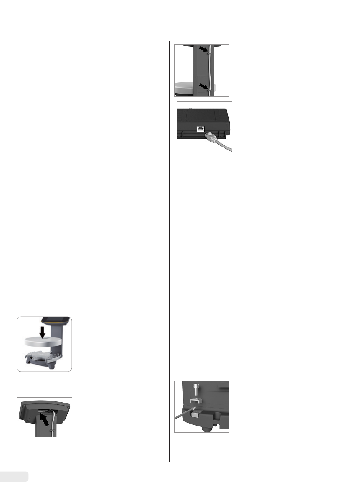
3.3 Choix du lieu d’installation
Choisissez un lieu d’installation adapté :
− Posez l’appareil sur une surface plane, stable et sans
vibrations.
− L’accès à l’appareil doit être libre en permanence.
− Manipulez les appareils avec soin conformément à l’indice
de protection IP. L’environnement doit être sécurisé en
conséquence.
− Dans des installations et des conditions ambiantes exigeant
des mesures de sécurité accrues, vous devez respecter les
instructions et les dispositions en vigueur dans votre pays.
Lors de l’installation, choisissez un emplacement adéquat afin
de ne pas exposer le comparateur aux influences suivantes :
− Chaleur due à un radiateur ou aux rayons du soleil
− Courants d’air directs causés par des fenêtres ou des portes
ouvertes ou encore par un climatiseur
− Vibrations pendant la pesée
− Passage de personnes
− Humidité de l’air très élevée
− Champs électromagnétiques
− Air très sec
Adaptation de l’appareil à l’environnement
De la condensation peut se former lorsqu’un appareil froid est
placé dans un environnement plus chaud. Dans ce cas, adaptez
l’appareil débranché du secteur à la température de la pièce
pendant environ deux heures avant de le raccorder au secteur.
3.4 Montage de la balance
AVIS
Ne branchez pas l’appareil au secteur avant d’avoir terminé le
montage.
3.4.1 Poser le plateau de pesée.
t Posez le plateau de pesée sur la
balance par le dessus.
t Insérez le câble de jonction
(bleu) dans les fixations à
l’arrière de la balance.
t Raccordez le câble de jonction
au convertisseur de jonction
antidéflagrant.
3.5 Raccordement de la mise à la terre
Qualification nécessaire : électricien qualifié
Le système antidéflagrant doit être installé conformément aux
règles techniques reconnues. Veuillez vous conformer pour cela
aux lois et directives nationales en vigueur dans votre pays.
Avant de mettre la balance en service, faites vérifier que le
système est dans un état conforme par un électricien ou bien
la direction et le contrôle d’un électricien.
Vérifiez si les autorités compétentes (par ex. les services de
l’Inspection du travail) doivent être informées. Des vérifications sont également nécessaires pendant le fonctionnement
du système.
La périodicité de ces vérifications doit être fixée de telle
manière que l’apparition de défauts éventuels, avec lesquels
il faut toujours compter, puisse être détectée à temps.
Ces vérifications doivent être réalisées au minimum tous les
trois ans. Pendant le fonctionnement, veillez à respecter les
prescriptions et directives correspondantes.
Avant de mettre le système en service pour la première fois,
assurez-vous qu’il n’y a aucun risque d’explosion dans cette
zone.
Lors de la mise en service, s’il se produit des erreurs
provoquées par des dommages dus au transport (par ex.
pas d’affichage, pas de rétroéclairage), débranchez la
balance du secteur et informez-en le Sartorius Service.
3.4.2 Connexion de la balance
t Branchez le câble de jonction
dans le connecteur femelle
RJ-45 à l’arrière de l’écran.
26 Manuel d’installation EVO1X1 | LAB1X
Seul un électricien formé en conséquence est autorisé
à effectuer l’installation de manière réglementaire et
conformément aux règles techniques reconnues.
Connectez la balance à la borne
d’équipotentialité à l’aide d’un
câble d’équipotentialité d’au moins
4 mm² de section transversale.
t Raccordez la cosse du câble
d’équipotentialité à la borne de
mise à la terre de la balance.
t Raccordez le câble d’équipo-
tentialité à la borne d’équipotentialité installée dans votre
usine.
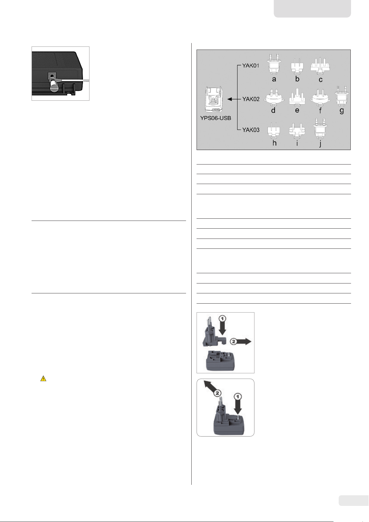
Connectez le convertisseur de
jonction antidéflagrant à la borne
d’équipotentialité à l’aide d’un
autre câble d’équipotentialité
d’au moins 4 mm² de section
transversale.
t Raccordez la cosse du câble
d’équipotentialité à la borne de
mise à la terre du convertisseur
de jonction antidéflagrant.
t Raccordez le câble d’équipo-
tentialité à la borne d’équipotentialité installée dans votre
usine.
3.6 Alimentation en courant
Qualification nécessaire : électricien qualifié
La balance est alimentée en courant par un PC/ordinateur
portable ou par le bloc d’alimentation YPS06-USB optionnel
(voir chapitre « 6 Accessoires », page 30) qui est livré avec
différents adaptateurs secteur spécifiques de divers pays.
AVIS
− Veillez à ce que la tension indiquée sur le bloc d’alimentation corresponde à la tension d’alimentation secteur sur
votre lieu d’installation (caractéristiques de connexion,
voir le chapitre « 8.1 Caractéristiques générales »,
page31).
− Si la tension secteur et le type de la fiche du bloc
d’alimentation ne correspondent pas aux normes en
vigueur, contactez votre représentant Sartorius.
L’alimentation électrique à l’aide du bloc d’alimentation est
nécessaire uniquement dans les cas suivants :
− si aucun PC ou ordinateur n’est disponible ;
− si, dans des cas exceptionnels, la tension de sortie du port
USB du PC ou de l’ordinateur portable n’est pas suffisante.
L’assemblage du bloc d’alimentation est décrit ci-après.
3.6.1 Installation du bloc d’alimentation
Français
Jeu d’adaptateurs secteur YAK01
Sachet Région/Pays
a) transparent Europe/UE (sauf la Grande-Bretagne)
b) bleu AVERTISSEMENT
c) jaune Grande-Bretagne
Jeu d’adaptateurs secteur YAK02
d) rouge Australie
e) turquoise Afrique du Sud
f) blanc Argentine
g) rose Brésil
Jeu d’adaptateurs secteur YAK03
h) marron clair Chine
i) noir Inde
j) vert Corée
t Enfoncez (1) et poussez (2)
l’adaptateur secteur dont
vous avez besoin pour votre
alimentation électrique dans
l’ouverture du module du bloc
d’alimentation.
L’adaptateur doit s’enclencher.
AVERTISSEMENT Électrocutions mortelles et dom-
t
mages sur l’appareil en cas d’adaptateur secteur inadapté !
Utilisez uniquement l’adaptateur secteur spécifique au
pays. Ne branchez jamais l’adaptateur secteur dans la prise
de courant s’il n’est pas inséré dans le bloc d’alimentation.
t Utilisez l’adaptateur adapté à votre réseau électrique :
Démontage/Remplacement de
l’adaptateur secteur
t Débloquez (1) l’adaptateur et
retirez-le (2).
Manuel d’installation EVO1X1 | LAB1X 27

Connexion à un PC/ordinateur
portable
t Branchez un câble USB (1) dans
le connecteur femelle droit du
convertisseur de jonction
1
antidéflagrant et raccordez le
2
câble au PC ou à l’ordinateur
portable. Lors de l’utilisation et
de l’installation du convertisseur de jonction antidéflagrant
YCO14-Y dans des atmosphères
explosives de la zone 2 ou de la
division 2, et si le câble USB (1)
ne contient aucun circuit
Raccordement au bloc d’alimentation (en option) ; pas de
raccordement si le convertisseur
YCO14-Y est installé dans une
atmosphère explosive de la
zone 2 ou de la division 2.
t Raccordez un autre câble
USB (2) au convertisseur de
jonction antidéflagrant.
t Raccordez le câble USB au bloc
d’alimentation YPS06-USB.
t Branchez le bloc d’alimentation
dans une prise électrique
(tension électrique).
électrique à sécurité intrinsèque, assurez-vous que le
câble est protégé contre tout
débranchement involontaire.
Consultez le dessin de contrôle
3.7 Système antivol
2021459 et les instructions de
sécurité 2023040 page 53,
ainsi que les illustrations
suivantes.
t Si nécessaire, fixez la balance
à l’aide du système antivol qui
se trouve à l’arrière.
t Fixez la bride
de décharge
de traction
2
2
YSR01 sur le
convertisseur (1) à
3.8 Mise à niveau
l’aide des
deux vis (2).
1
Mise à niveau du modèle PMA.HD et des modèles
approuvés pour l’utilisation en métrologie légale
La mise à niveau de la balance permet de compenser une
inclinaison ou des inégalités de la surface de travail sur
laquelle est installée la balance. Un positionnement
t Fixez le câble
USB à la
bride de
2
3
décharge de
traction (1)
à l’aide du
1
2
collier de
serrage (3)
et des deux
vis (4).
t Obturez le
port USB (5)
5
à l’aide du
capuchon
de protection (6).
horizontal exact garantit des résultats de pesée précis.
La balance doit être remise à niveau et ajustée à chaque
fois qu’elle est déplacée.
t Tournez les deux pieds de réglage
comme indiqué sur l’illustration
12*
9*
jusqu’à ce que la bulle d’air du
niveau se trouve au milieu du
cercle.
6*
− Bulle d’air à « 12 h » : tournez
les deux pieds de réglage dans le
sens horaire.
* Heure
− Bulle d’air à « 3 h » : tournez le
pied de réglage gauche dans le
sens horaire et le pied de réglage
droit dans le sens anti-horaire.
− Bulle d’air à « 6 h » : tournez les
deux pieds de réglage dans le
6
sens anti-horaire.
− Bulle d’air à « 9 h » : tournez le
pied de réglage gauche dans le
sens anti-horaire et le pied de
réglage droit dans le sens horaire.
28 Manuel d’installation EVO1X1 | LAB1X

0
30
Français
3.9 Temps de préchauffage
Utilisation en métrologie légale de balances
approuvées :
Observer un temps de préchauffage d’au moins
24 heures après le premier raccordement au secteur.
Après le premier raccordement au secteur,
la balance a besoin d’un temps de préchauffage d’au moins 30 minutes afin de
pouvoir fournir des résultats précis.
L’appareil atteint alors la température
nécessaire à son bon fonctionnement.
4 Nettoyage et maintenance
4.1 Nettoyage
Avant de procéder au nettoyage du bloc d’alimentation, du
convertisseur de jonction antidéflagrant ou de la balance :
mettez tous les appareils hors tension.
AVERTISSEMENT Danger dû au risque électrique !
Débranchez le bloc d’alimentation (optionnel). Si un câble de
données est connecté au convertisseur de jonction antidéflagrant, débranchez-le. N’ouvrez jamais la balance ni le bloc
d’alimentation. Ils ne contiennent pas de pièces qui doivent
être nettoyées, réparées ou remplacées par l’utilisateur.
AVIS
Ne nettoyez pas les parties suivantes avec de l’acétone ou des
produits de nettoyage corrosifs :
− entrée de la fiche secteur ;
− interface de données ;
− plaques et tous les autres éléments en plastique.
Procédure
t Débranchez l’appareil de l’alimentation électrique.
t AVIS Assurez-vous qu’aucun liquide ni aucune poussière
ne pénètre dans la balance ou dans le bloc d’alimentation.
t AVIS Des produits de nettoyage inadaptés risquent de
provoquer la corrosion de l’appareil ou d’endommager
celui-ci !
t N’utilisez pas de produits de nettoyage corrosifs,
agressifs et contenant du chlore.
t N’utilisez pas de produits de nettoyage qui contiennent
des composants récurants (par ex. des produits à
récurer, laine d’acier).
t Pour nettoyer la balance, utilisez uniquement des
brosses souples et des chiffons.
t N’utilisez pas de produits de nettoyage qui contiennent
des solvants.
Nettoyage du panneau de commande
t Avant de nettoyer le panneau de commande : éteignez
l’appareil pour éviter d’effectuer involontairement des
saisies lorsque vous touchez le panneau.
Nettoyage du boîtier de l’appareil
t Essuyez le boîtier avec un chiffon légèrement humide. En
cas de saletés plus importantes, utilisez un savon doux.
t Ensuite, essuyez l’appareil avec un chiffon doux.
4.2 Maintenance
Il est conseillé d’effectuer la maintenance de votre balance
au moins une fois par an pour garantir en permanence des
mesures précises. À cet effet, le Sartorius Service propose
différents contrats de maintenance modulables selon vos
besoins.
Un certificat de calibrage doit toujours être délivré dans le
cadre de la maintenance. Faites vérifier régulièrement la
sécurité du bloc d’alimentation et de ses connecteurs par
un électricien qualifié (par ex. tous les deux ans).
5 Recyclage
5.1 Instructions de décontamination
Conformément aux directives de l’Union européenne relatives
aux matières dangereuses, il incombe au propriétaire d’appareils ayant été en contact avec des matières dangereuses de
les éliminer de manière appropriée et de fournir une déclaration pour leur transport.
AVERTISSEMENT
Risque de blessures causées par des appareils contaminés !
Les appareils contaminés par des matières dangereuses
(contaminations NBC) ne sont pas repris pour être réparés
ou éliminés.
5.1.1 Remarques concernant l’élimination et
le recyclage
L’appareil ainsi que les accessoires ne doivent pas être jetés
dans les ordures ménagères normales, car ils sont fabriqués à
partir de matériaux de grande qualité pouvant être recyclés et
réutilisés. Tous les éléments doivent être éliminés de manière
appropriée par des entreprises spécialisées.
L’emballage est composé de matériaux écologiques qui
peuvent servir de matières secondaires.
5.1.2 Recyclage
Conditions requises
L’appareil a été décontaminé.
Procédure
t Éliminez l’appareil. Consultez à cet effet les consignes
d’élimination disponibles sur notre site Internet
(www.sartorius.com).
t Recyclez l’emballage conformément aux réglementations
en vigueur dans votre pays.
Manuel d’installation EVO1X1 | LAB1X 29

6 Accessoires
7 Codification du
Accessoires Référence
Bloc d’alimentation (5 V/900 mA) YPS06-USB
Câble USB, 5 m
Jeu d’adaptateurs secteur pour YPS06-USB YAK01
− États-Unis et Japon
− Europe/UE
− Grande-Bretagne
Jeu d’adaptateurs secteur pour YPS06-USB YAK02
− Australie
− Afrique du Sud
− Argentine
− Brésil
Jeu d’adaptateurs secteur pour YPS06-USB YAK03
− Inde
− Corée
− Chine
Convertisseur de jonction antidéflagrant
Convertisseur de jonction antidéflagrant
Câble de jonction
entre le convertisseur et la balance, 10 m
entre le convertisseur et la balance, 20 m
entre le convertisseur et la balance, 30 m
Décharge de traction
Câble d’équipotentialité
Cache de protection pendant le travail
pour le panneau de commande,
boîte de 10
pour la colonne, PMA.Evolution,
boîte de 10
pour le plateau de pesée,
PMA.Evolution, boîte de 10
Poids d’ajustage
pour PMA.Evolution :
− 5 kg, classe de précision F2
− 2 kg, classe de précision F2
− 1 kg, classe de précision F2
pour PMA.HD :
− 2 kg, classe de précision F1
− 1 kg, classe de précision F1
, 2 m
YCC01-0040M5
YCO14-Y
YCO14-Z
YCC01-0052M10
YCC01-0052M20
YCC01-0052M30
YSR01
YCC01-X046M2
YDC03PMA10
YDC03PMA-CO10
YDC03PMA-WP10
YCW654-AC-00
YCW624-AC-00
YCW614-AC-00
YCW623-AC-00
YCW613-AC-00
numéro de série
1725
La date de fabrication de l’appareil est codée dans le numéro
de série. La structure est la suivante :
AMM x x x x x
A Année
3 2014-2020
4 2021-2027
5 2028-2034, etc.
La colonne de l’année A représente le numéro du groupe
d’années qui définit une période de respectivement 7 ans.
À l’intérieur de chaque groupe d’années, on augmente les
chiffres des mois (M M) en partant de 13.
Année : 2015 2016 2017 2018 2019 ...
MM : 25-36 37-48 49-60 61-72 73-84 ...
Exemple :
328xxxxx (avril 2015). « xxxxx » est un numéro continu qui,
tous les mois, recommence à 1.
30 Manuel d’installation EVO1X1 | LAB1X

Français
8 Caractéristiques techniques
8.1 Caractéristiques générales
Caractéristique Unité Valeur
Balance
Alimentation électrique Seulement via l’interface USB ou le bloc d’alimentation
Sartorius YPS06-USB
Tension d’entrée V
Puissance absorbée W 2,0 (standard)
Autres données IP40 selon EN 60529/CEI 60529
Conditions ambiantes
Les caractéristiques techniques sont valables pour les conditions ambiantes suivantes :
Environnement Utilisation uniquement à l’intérieur
Température ambiante* °C de +10 à +30
Capacité opérationnelle °C Garantie entre +5 et +40
Stockage et transport °C de -10 à +60
Humidité relative de l’air % Jusqu’à 80 % pour des températures jusqu’à 30 °C sans condensation,
Port d’interface du convertisseur de
jonction antidéflagrant
Compatibilité électromagnétique Selon EN 61326-1/IEC61326-1 : appareils électriques de mesure,
Immunité aux émissions parasites Exigences de base
Émissions parasites Classe B
DC
de +4,5 à 5,0
décroissance linéaire jusqu’à 50 % d’humidité relative de l’air à 40 °C
USB, type B
de commande et de laboratoire – Prescriptions relatives à la CEM –
Partie 1 : Exigences générales
Convient à une utilisation dans les zones résidentielles et les zones
directement raccordées au réseau basse tension alimentant (également)
des habitations.
Les balances approuvées pour une utilisation en métrologie légale selon
l’UE répondent aux exigences de la directive européenne 2014/31/EU
avec les normes EN45501:2015 ou OIML R76:2006.
* Pour les balances approuvées pour l’utilisation en métrologie légale
selon l’UE, voir les indications apposées sur la balance.
** Pour les balances approuvées pour l’utilisation en métrologie légale
selon l’UE, la législation en vigueur s’applique.
Programmes d’application sélectionnables Recalcul, calcul avec un facteur, formulation
Bloc d’alimentation YPS06-USB
Bloc d’alimentation USB (5 V/900 mA) Type FW7712 (désignation du fabricant)
Primaire 100 à 240 V~, –10 %/+10 %, 50 à 60 Hz, 0,125 A
Secondaire 5 V
Autres données Classe de protection II
Convertisseur de jonction antidéflagrant
YCO14-Y | YCO14-Z
Autres données IP40 selon EN 60529/CEI 60529
, ± 5 %, 900 mA (max.)
DC
IP40 selon EN 60529/CEI 60529
Manuel d’installation EVO1X1 | LAB1X 31

8.2 Caractéristiques techniques spécifiques des différents modèles
Modèle
Caractéristique Unité Valeur Valeur
PMA.Evolution PMA.HD
EVO1X LAB1X
Étendue de pesée g 7 500/999,95 2200
Précision de lecture g 0,1/0,05 0,01
Étendue de tarage (soustractive) g -7500 -2200
Valeur du poids d’ajustage externe /
classe de précision
Diamètre du plateau de pesée mm 233 180
Poids net kg 2,4 2,3
kg 1, 2, 5 /
F2 ou mieux
1, 2 /
F1 ou mieux
8.3 Modèles approuvés pour l’utilisation en métrologie légale avec approbation CE de type : caractéristiques techniques spécifiques des différents modèles
Caractéristique Unité Valeur
Modèle PMA.Evolution, EVO1X
Classe de précision II
Type PMA-EV
Étendue de pesée maximale g 7500
Échelon réel d g 0,1
Échelon de vérification e g 1
Plage de température +10 °C à +30 °C
Étendue de compensation de tare (soustractive)
< 100 % de l’étendue de pesée maximale
Caractéristique Unité Valeur
Modèle PMA.HD, LAB1X
Classe de précision III
Type PMA-HD
Étendue de pesée maximale g 2200
Échelon réel d g 1
Échelon de vérification e g 1
Plage de température +10 °C à +40°C
Étendue de compensation de tare (soustractive)
< 100 % de l’étendue de pesée maximale
9 Déclaration de conformité UE
Par la déclaration de conformité ci-jointe, la société Sartorius atteste que l’appareil est conforme aux directives mentionnées.
La déclaration de conformité fournie avec la balance est valide pour les balances approuvées pour l’utilisation en métrologie
légale dans l’Espace Économique Européen. Il est obligatoire de la conserver.
32 Manuel d’installation EVO1X1 | LAB1X

Español
Índice
1
Acerca de este documento ..........................33
1.1 Validez......................................33
1.2 Símbolos ....................................33
2 Seguridad .......................................33
2.1 Uso previsto .................................33
2.2 Protección contra explosiones ..................34
2.3 Cualificación del personal......................34
2.4 Importancia de estas instrucciones de uso ........35
2.5 Perfecto estado del aparato ....................35
2.6 Trabajos en el equipo eléctrico del aparato .......35
2.7 Equipo de protección individual.................35
2.8 Indicaciones de seguridad para el manejo
del aparato ..................................35
3 Instalación ......................................35
3.1 Volumen de suministro ........................35
3.2 Desembalaje . . . . . . . . . . . . . . . . . . . . . . . . . . . . . . . . . 35
3.3 Elección del lugar de colocación ................35
3.4 Montar la balanza ............................36
3.5 Puesta a tierra ...............................36
3.6 Establecer alimentación de tensión..............37
3.7 Protección antirrobo ..........................38
3.8 Nivelación...................................38
3.9 Tiempo de calentamiento previo ................39
4 Limpieza y mantenimiento ........................39
4.1 Limpieza ....................................39
4.2 Mantenimiento...............................39
1.2.1 Advertencias
ADVERTENCIA
Esta indicación identifica un posible riesgo que podría tener
como consecuencias la muerte o graves lesiones corporales si
no se evita.
ATENCIÓN
Identifica un riesgo que podría tener como consecuencias
lesiones corporales medias o leves si no se evita.
AVISO
Identifica un peligro que podría provocar daños materiales si
no se evita.
1.2.2 Otros medios de representación
t
y
[ ]
Instrucción de actuación: describe tareas que
deben realizarse.
Resultado: describe el resultado de las actividades
realizadas.
Hace referencia a elementos de manejo y visualización.
Este símbolo hace referencia a la metrología legal
para balanzas de conformidad evaluada (verificadas).
Más adelante aparece el término “verificado” para
la expresión técnica de la evaluación de la conformidad.
5 Eliminación......................................39
5.1 Indicaciones para la descontaminación...........39
6 Accesorios.......................................40
7 Codificación del número de serie ..................40
8 Datos técnicos ...................................41
8.1 Datos generales ..............................41
8.2 Datos específicos de modelos...................42
Modelos verificados con certificado de aprobación CE
8.3
de tipo: datos técnicos específicos de cada modelo
9 Declaración de conformidad UE ...................42
...42
1 Acerca de este documento
1.1 Validez
Estas instrucciones de manejo corresponden a las balanzas
para la mezcla de pinturas de las series de modelos:
− EVO1X
− LAB1X
1.2 Símbolos
El término “aparato” utilizado en estas instrucciones identifica
siempre a la combinación de balanza, fuente de alimentación
y convertidor Ex-Link.
Ilustraciones de la pantalla de usuario
Las figuras en este manual se basan en balanzas “estándar”.
En las balanzas calibradas pueden haber pequeñas diferencias
en la forma en que se muestran los avisos y en los protocolos
de las figuras. En los casos importantes para el funcionamiento, se explicarán las diferencias en el texto.
2 Seguridad
2.1 Uso previsto
Esta balanza solo es adecuada para la mezcla de pinturas y
lacas. Para contener los materiales se deben usar envases
apropiados.
La balanza puede controlarse tanto de forma independiente
con ayuda de una pantalla como con un software de aplicación instalado en un PC (p. ej. una aplicación de mezcla de
pinturas del fabricante de pinturas). Para ello, el ordenador se
conectará al convertidor Ex-Link por medio de un cable USB.
Deberán observarse las indicaciones sobre la protección contra
explosiones en el Capítulo 2.2, página 34.
Estas instrucciones forman parte del aparato. El aparato está
diseñado para utilizarse exclusivamente de acuerdo con las
presentes instrucciones.
Instrucciones de instalación de EVO1X | LAB1X 33

Cualquier uso distinto se considera inadecuado. Si el aparato
no se va a utilizar conforme a las instrucciones, las medidas
de protección del aparato pueden verse afectadas. Esto puede
provocar incalculables daños personales o materiales.
En caso de uso en instalaciones y condiciones ambientales
con requisitos de seguridad mayores, se deben respetar las
condiciones y disposiciones del país.
Uso en Australia, Nueva Zelanda:
Deberán observarse el Certificado de Conformidad IECEx FME
14.0008X, así como las Instrucciones de Seguridad 2023040 a
partir de Página 53.
2.3 Cualificación del personal
Condiciones de uso para el aparato
Utilizar el aparato únicamente en edificios.
Utilizar el aparato únicamente con el equipamiento y en las
condiciones de funcionamiento que se describen en los datos
técnicos de estas instrucciones.
No desmontar ni modificar técnicamente el aparato de
manera arbitraria. Las medidas de desmontaje y las modificaciones técnicas necesitan la autorización previa y por escrito
de Sartorius.
El aparato, así como los accesorios suministrados por Sartorius, no deben someterse a temperaturas extremas, vapores
químicos agresivos, humedad, golpes, vibraciones ni campos
electromagnéticos fuertes. Respete las condiciones de uso
especificadas en los datos técnicos.
Tanto los cables de conexión de aparatos como los recubrimientos de los hilos interiores del cable están fabricados en
PVC. Mantenga alejado de estos conductores cualquier
producto químico agresivo para estos materiales.
2.2 Protección contra explosiones
Uso en el ámbito de la aplicación de la directiva ATEX:
− El modelo de la serie EVO1X | LAB1X es, según la directiva
2014/34/UE, un aparato de la categoría 2, adecuado para
áreas potencialmente explosivas de la zona 1.
− El convertidor Ex-Link YCO14-Z, como medio motriz
eléctrico que forma parte del conjunto, solo se puede
instalar fuera del área con peligro de explosión.
− El convertidor Ex-Link YCO14-Y es un medio motriz
eléctrico que forma parte del conjunto que se puede
utilizar en la zona 2.
− Las identificaciones de los dispositivos se deben extraer
de los EU-Type Examination Certificates (certificados de
comprobación del tipo de construcción de la UE) a partir
de Página 53. Observar las notas de seguridad según el
dibujo adjunto 2023040 a partir de Página 53.
Uso en Canadá y en los EE. UU.:
Las balanzas intrínsecamente seguras de las series de modelos
EVO1X y LAB1X son apropiadas para el uso en la clase I,
división 1, así como la clase I, zona 1. El convertidor Ex-Link
YCO14-Y se puede utilizar en la clase I, división 2 y clase I,
zona 2.
Deberán observarse los Certificados de Conformidad
FM16US0226X y FM16CA0124X, así como el Plano de Control
2021459 a partir de Página 53.
Estas instrucciones van dirigidas a los grupos de destinatarios
mencionados más abajo. Todas las personas que utilicen el
aparato deberán contar con los conocimientos y responsabilidades mencionados.
Si en la tareas descritas en estas instrucciones no se indica
ninguna cualificación, significa que estas están orientadas
al grupo de destinatarios “Usuario”.
En el caso de que algunas tareas deban realizarlas otros
grupos de destinatarios o el Sartorius Service, se indica la
cualificación necesaria en la descripción de la tarea.
Grupo de
destinatarios
Usuario El usuario está familiarizado con el uso del
Ingeniero
técnico/jefe
de laboratorio
Personal
electricista
especializado
Operador El operador del aparato es responsable
Conocimientos y responsabilidades
aparato y los procesos de trabajo relacionados
con este. Conoce los posibles peligros relacionados con el uso del aparato y sabe cómo
evitarlos.
El usuario ha recibido formación sobre el uso
del aparato. La instrucción la realiza durante
la puesta en marcha el ingeniero de operaciones o el jefe de laboratorio, o bien el operador
del aparato.
El ingeniero técnico/jefe de laboratorio es
el encargado de tomar las decisiones relacionadas con el uso y la parametrización del
aparato.
El ingeniero técnico/jefe de laboratorio ha
recibido formación sobre el uso del aparato.
La instrucción inicial se produce en el marco
de la puesta en marcha y la imparte el
Sartorius Service o el operador.
El personal electricista especializado, gracias
a su formación técnica, conocimientos,
experiencia y conocimiento de las normas
aplicables, puede evaluar los trabajos
encomendados y detectar los posibles
peligros.
del cumplimiento de las disposiciones de
seguridad y protección en el trabajo.
El operador debe asegurar que todas las
personas que trabajan con el aparato tienen
acceso a la información relevante y han sido
instruidas en el manejo del aparato.
34 Instrucciones de instalación de EVO1X | LAB1X

Español
2.4 Importancia de estas instrucciones de uso
El incumplimiento de las instrucciones puede tener graves
consecuencias como, por ejemplo, peligros para personas por
influencias eléctricas, mecánicas o químicas.
t Antes de efectuar cualquier trabajo en la máquina, leer las
instrucciones atenta y completamente.
t En caso de pérdida del manual puede solicitar uno nuevo o
descargar el manual más reciente de la página de Internet
de Sartorius (www.sartorius.com).
t La información del manual de instrucciones debe estar al
alcance de todas las personas que trabajan con el aparato.
2.5 Perfecto estado del aparato
Un aparato dañado puede ocasionar funcionamientos
incorrectos o dar lugar a peligros difíciles de identificar.
t El aparato debe utilizarse únicamente en un estado
perfecto en razón de la seguridad.
t Desconecte el aparato dañado de la corriente de
inmediato.
t Encargue la reparación de daños al Sartorius Service
de inmediato.
− No toque la superficie de la pantalla de manejo con
objetos puntiagudos, cortantes, duros ni rugosos, sino
exclusivamente con un lápiz táctil previsto para este fin o
con las yemas de los dedos. Para limpiar, no utilice bajo
ningún concepto prendas de vestir (como mangas, etc.) ni
esponjas, ya que pueden arañar la superficie (p. ej. debido
a remaches o botones en las mangas o a arena en las
esponjas).
− Evite que el vidrio de la pantalla de manejo y la carcasa de
plástico se carguen electrostáticamente.
Riesgo de daños en la balanza.
No cierre nunca la lata de pintura con un
martillo mientras esta se encuentre sobre
el plato de pesaje.
Coloque la lata de pintura sobre una
superficie estable para cerrarla.
3 Instalación
3.1 Volumen de suministro
2.6 Trabajos en el equipo eléctrico del aparato
Todos los trabajos y modificaciones en el equipo eléctrico del
aparato deben encomendarse exclusivamente al Sartorius
Service. Solo Sartorius Service puede abrir el aparato.
Sello en las variantes verificadas
El legislador exige un sello de la balanza verificada. Para garantizar la seguridad de los aparatos
verificados se coloca una marca adhesiva con
el nombre “Sartorius”. En caso de que esta se
elimine, se extingue la validez de la verificación
y la balanza debe regularse de nuevo. Para las
balanzas verificadas que se vayan a emplear en
el EEE es válida la verificación efectuada y la
declaración de conformidad adjuntada. Guárdela
sin falta.
2.7 Equipo de protección individual
El equipo de protección individual protege contra peligros
derivados de los materiales procesados.
t Si el área de trabajo o el proceso en el que se va a utilizar
el aparato requiere un equipo de protección individual,
utilizar el equipo de protección individual.
2.8 Indicaciones de seguridad para el manejo del aparato
− No dañe el vidrio de la pantalla de manejo (p. ej. por
caídas de objetos, golpes o presión excesiva). Si la placa
de vidrio sufre algún daño, desenchufe inmediatamente
el aparato de la alimentación eléctrica.
Modelo PMA.Evolution PMA.HD
Plato de pesaje grande:
d 233 mm
Plato de pesaje pequeño:
d 180 mm
Cable USB x x
Convertidor Ex-Link x x
Cable de compensación de
potencial
Cable de enlace del convertidor
a la balanza
Instrucciones de instalación x x
x –
– x
x x
x x
3.2 Desembalaje
Procedimiento
t Abra el embalaje y saque cuidadosamente todas las piezas.
t Compruebe inmediatamente después de desembalar si el
aparato tiene daños externos.
t Si el aparato se va a almacenar temporalmente, hacerlo
de acuerdo con las condiciones ambientales (ver Capítulo “8.1 Datos generales”, página 41).
t Conserve todas las piezas del embalaje original para un
eventual envío de retorno. Antes del envío, desconecte
todos los cables.
3.3 Elección del lugar de colocación
Elegir el lugar correcto
− Colocar el aparato sobre una superficie estable, plana y sin
muchas sacudidas.
Instrucciones de instalación de EVO1X | LAB1X 35

− Mantener el acceso al aparato en todo momento libre.
− Maneje los aparatos cuidadosamente, cumpliendo las
normas de protección IP. El entorno debe estar correspondientemente asegurado.
− En caso de uso en instalaciones y condiciones ambientales
con requisitos de seguridad mayores, se deben respetar las
condiciones y disposiciones del país.
Para la colocación, evitar lugares con influencias inadecuadas:
− Calor (calefacción, radiación solar)
− Corriente de aire directa por ventana abierta, instalación
de aire acondicionado o puertas
− Sacudidas durante la medición
− Lugar de tráfico de personas
− Humedad del aire extremadamente alta
− Campo electromagnético
− Aire extremadamente seco
Aclimatizar
Cuando un aparato frío se lleva a un entorno caluroso, esto
puede causar condensación de la humedad del aire (empañamiento). Por eso, aclimatice el aparato desconectado de la
tensión, durante unas 2 horas, antes de conectarlo nuevamente a la tensión de alimentación.
3.4 Montar la balanza
AVISO
Para todos los trabajos de montaje, el aparato debe estar
desconectado de la alimentación eléctrica.
3.4.1 Colocar el plato de pesaje
t Conecte el cable Link al
convertidor Ex-Link.
3.5 Puesta a tierra
Cualificaciones necesarias: Personal electricista especializado
El aparato con protección contra explosiones debe instalarse
según las reglas reconocidas de la técnica. Debe observar las
leyes/reglamentaciones nacionales correspondientes.
Antes de poner en funcionamiento la balanza, debe controlarse el estado correcto, bien por un electricista o bien bajo
la dirección y supervisión de un electricista.
Verifique si es necesario informar a los organismos pertinentes
(p. ej. oficina de inspección industrial). También son necesarios
controles durante el funcionamiento del aparato.
Los plazos deben calcularse de manera que los defectos que
se originen, con los que debe contarse, puedan reconocerse
a tiempo. Los controles deben realizarse por lo menos cada
tres años. Durante la utilización deberán cumplirse todas las
obligaciones y directrices pertinentes.
Ponga en funcionamiento el aparato solamente después de
asegurarse de que el área no presenta riesgo de explosión.
Si al ponerlo en funcionamiento se presentan problemas
provocados por daños durante el transporte (p. ej. ninguna
indicación, sin retroiluminación), desconectar la balanza de
la red e informar al Sartorius Service.
t Ponga el plato de pesaje desde
arriba sobre la balanza.
3.4.2 Conexión de la balanza
t Enchufe el conector del cable
Link de la parte posterior de la
pantalla en la toma RJ-45.
t Haga pasar el cable Link (azul)
por el soporte de cable de la
parte posterior de la balanza.
La instalación debe realizarla conforme a las instrucciones un
electricista formado especialmente para ello y según las reglas
de la técnica.
Conecte la balanza a la compensación de potencial utilizando un
cable de compensación de potencial con una sección mínima de
4 mm².
t Conecte el terminal del cable
de compensación de potencial
al borne de tierra de la balanza.
t Conecte el cable de compensa-
ción de potencial a la compensación de potencial del cliente.
36 Instrucciones de instalación de EVO1X | LAB1X

Conecte el convertidor Ex-Link a la
compensación de potencial utilizando un segundo cable de compensación de potencial con una
sección mínima de 4 mm².
t Conecte el terminal del cable
de compensación de potencial
al borne de tierra del convertidor Ex-Link.
t Conecte el cable de compensa-
ción de potencial a la compensación de potencial del cliente.
3.6 Establecer alimentación de tensión
Español
Cualificaciones necesarias: Personal electricista especializado
La alimentación eléctrica a la balanza se realiza a través de
un ordenador de escritorio/portátil o mediante la fuente de
alimentación YPS06-USB (ver Capítulo “6 Accesorios”,
página 40), que se suministra con diferentes adaptadores
de red específicos para cada país.
AVISO
− El valor de tensión eléctrica indicado en la fuente de
alimentación debe coincidir con la tensión de red local
(para los datos de conexión, ver capítulo «8.1 Datos
generales”, página 41).
− Si la tensión de red indicada o el modelo de enchufe de
la fuente de alimentación no se corresponden con las
normas utilizadas en el país, póngase en contacto con
la representación de Sartorius más próxima.
La alimentación eléctrica con la fuente de alimentación solo
será necesaria:
− cuando no esté disponible un PC o portátil,
− en casos excepcionales cuando la tensión de salida de la
interfaz USB del PC o portátil no es suficiente.
El ensamblaje de la fuente de alimentación se describe a
continuación.
3.6.1 Montar fuente de alimentación
Juego de adaptadores de red YAK01
Bolsa Región/País
a) transparente Europa/UE (excepto Gran Bretaña)
b) azul Estados Unidos
c) amarillo Gran Bretaña
Juego de adaptadores de red YAK02
d) rojo Australia
e) turquesa Sudáfrica
f) blanco Argentina
g) rosa Brasil
Juego de adaptadores de red YAK03
h) marrón claro China
i) negro India
j) verde Corea
t Presione (1) y desplace (2) el
adaptador de red requerido
para su suministro de corriente
en la apertura del módulo de
la fuente de alimentación.
El adaptador de red debe
engancharse.
ADVERTENCIA Peligro de electrocución y de daños en
t
el aparato por un adaptador de red incorrecto. Utilizar solo
el adaptador de red específico del país. No enchufe jamás
el adaptador de red separado de la fuente de alimentación.
t Utilice el adaptador de red adecuado para su red eléctrica:
Desmontaje/sustitución del
adaptador de red
t Desbloquee (1) el adaptador de
red y sáquelo (2).
Instrucciones de instalación de EVO1X | LAB1X 37

Conexión a un ordenador de
escritorio/portátil
t Conecte un cable USB (1) a la
toma derecha del convertidor
Ex-Link y a un ordenador de
1
escritorio o portátil. Si se
2
instala y utiliza el convertidor
Ex-Link YCO14-Y en áreas
potencialmente explosivas de
la zona 2 o la división 2 y el
cable USB (1) no contiene
ningún circuito eléctrico con
seguridad intrínseca, el cable
se deberá fijar para evitar una
Conexión a la fuente de
alimentación (opcional); no en
el caso de YCO14-Y, si esta
está instalada en un área
potencialmente explosiva de
la zona 2 o la división 2.
t Conecte un segundo cable USB
(2) al convertidor Ex-Link.
t Conecte el cable USB a la
fuente de alimentación
YPS06-USB.
t Conecte la fuente de alimen-
tación a una toma de pared
(tensión de red).
desconexión. Ver el Plano de
Control 2021459 y las Instrucciones de Seguridad 2023040 a
partir de Página 53, así
como las siguientes ilustraciones.
t Fije la brida
de descarga
3.7 Protección antirrobo
t Asegure la balanza por el lado
posterior, en caso necesario.
de tracción
2
2
YSR01 con
los dos
tornillos (2)
al convertidor
(1).
1
3.8 Nivelación
Nivelación del modelo PMA.HD y de modelos verificados
t Fije el cable
USB con la
abrazadera
2
3
(3) y los dos
tornillos (4)
a la brida de
1
descarga de
tracción (1).
2
t Cierre la
toma USB
5
izquierda (5)
con la tapa
de protección
(6).
Con la nivelación de la balanza pueden compensarse inclinaciones en el lugar de instalación. Una colocación exacta y
horizontal de la balanza garantiza resultados de pesaje
precisos.
La balanza debe nivelarse y ajustarse de nuevo en caso
necesario cada vez que se cambie su ubicación.
t Gire los dos tornillos de las patas
tal y como se muestra en la
12
9
figura, hasta que la burbuja de
aire del nivel esté en el centro
del círculo.
6
− Burbuja a las “12 horas”: girar
las dos patas en sentido horario.
− Burbuja a las “3 horas”: girar
* horas
la pata izquierda en sentido
horario, la pata derecha en
sentido antihorario.
6
− Burbuja a las “6 horas”: girar las
dos patas en sentido antihorario.
− Burbuja a las “9 horas”: girar
la pata izquierda en sentido
antihorario, la pata derecha en
sentido horario.
38 Instrucciones de instalación de EVO1X | LAB1X

0
30
Español
3.9 Tiempo de calentamiento previo
Utilización de balanzas verificadas para la
metrología legal:
Respetar un tiempo de precalentamiento de
mínimo 24 horas después de conectarla a la red
eléctrica.
Para obtener resultados exactos, la balanza
necesita un tiempo de precalentamiento
mínimo de 30 minutos después de conectarla por primera vez al suministro de
corriente.
En ese momento, el aparato habrá alcanzado la temperatura de funcionamiento
necesaria.
4 Limpieza y mantenimiento
4.1 Limpieza
Antes de la limpieza del aparato de red, del convertidor
Ex-Link o de la balanza, desconecte todos los aparatos.
ADVERTENCIA Peligro por tensión eléctrica.
Desconecte la fuente de alimentación (opcional) de la red
eléctrica. En caso necesario, desconecte el cable de datos
conectado al convertidor Ex-Link. No abra jamás la balanza
ni la fuente de alimentación. No contienen piezas pequeñas
que el usuario puede limpiar, reparar o sustituir.
AVISO
No limpie las siguientes piezas con acetona o productos de
limpieza agresivos:
− Entrada del conector de alimentación
− Interfaz de datos
− Rótulos y los demás componentes de plástico
Procedimiento
t Desconectar el aparato del suministro eléctrico.
t AVISO Asegúrese de que no entre polvo ni líquido en la
balanza o la fuente de alimentación.
t AVISO Corrosión y daños en el aparato por productos de
limpieza inadecuados.
t No utilizar productos de limpieza cáusticos, clorados
ni agresivos.
t No utilizar productos de limpieza que incluyan
componentes decapantes, como por ejemplo crema
limpiadora o lana de acero.
t Utilice un cepillo blando y un paño para la limpieza.
t No utilizar productos de limpieza con disolventes.
Limpieza de la carcasa
t Limpiar la carcasa con un paño de limpieza ligeramente
humedecido. Utilizar agua jabonosa para eliminar las
impurezas más persistentes.
t A continuación, limpie el aparato con un paño suave.
4.2 Mantenimiento
Para garantizar la seguridad de medición constante de su
balanza, recomendamos un mantenimiento regular, al menos
una vez al año. Sartorius Service le ofrece al efecto diversos
contratos de mantenimiento, que podemos adecuar a sus
necesidades.
En el marco de todos los mantenimientos, se deberá emitir
siempre un certificado de calibración. Haga realizar una
comprobación de seguridad técnica de la fuente de alimentación y sus conexiones a un electricista en intervalos adecuados
(p. ej. cada 2 años).
5 Eliminación
5.1 Indicaciones para la descontaminación
Según dictan las normas de la UE del Reglamento Europeo
sobre sustancias peligrosas, en caso de que los aparatos hayan
entrado en contacto con sustancias peligrosas, son los propietarios de estos los responsables de eliminarlos adecuadamente
y de expedir la correspondiente declaración para su transporte.
ADVERTENCIA
Peligro de lesiones por aparatos contaminados.
No se admitirá para su reparación y desecho ningún aparato
contaminado con sustancias peligrosas (contaminación ABC).
5.1.1 Indicaciones para la eliminación
El aparato y los accesorios incluidos no deben desecharse
junto con los residuos domésticos, ya que están fabricados con
materiales de gran calidad que se pueden reciclar y reutilizar.
Todas las piezas deben desecharse correctamente a través de
centros de recogida de residuos.
El embalaje está compuesto por materiales respetuosos con
el medio ambiente que se pueden utilizar como materia
prima reciclada.
5.1.2 Eliminación
Requisitos
Este aparato está descontaminado.
Limpieza del panel de control
t Antes de limpiar el panel de control, desconecte el
aparato para evitar la introducción accidental de datos
por pulsaciones involuntarias.
Procedimiento
t Desechar el aparato. Usar para ello las indicaciones de
eliminación de nuestra página web (www.sartorius.com).
t Desechar el embalaje de conformidad con las normas locales.
Instrucciones de instalación de EVO1X | LAB1X 39

6 Accesorios
7 Codificación del
Accesorios
Fuente de alimentación (5 V/900 mA) YPS06-USB
Cable USB, 5 m
Juego de adaptadores de conector de red
para YPS06-USB
− EE. UU. y Japón
− Europa/UE
− Gran Bretaña
Juego de adaptadores de conector de red
para YPS06-USB
− Australia
− Sudáfrica
− Argentina
− Brasil
Juego de adaptadores de conector de red
para YPS06-USB
− India
− Corea
− China
Convertidor Ex-Link
Convertidor Ex-Link
Cable Link
del convertidor a la balanza, 10 m
del convertidor a la balanza, 20 m
del convertidor a la balanza, 30 m
Descarga de tracción
Cable de compensación de potencial
Cubierta protectora de uso
para el panel de control,
paquete de 10
para el soporte, PMA.Evolution,
paquete de 10
para el plato de pesaje,
PMA.Evolution, paquete de 10
Pesas de ajuste
para PMA.Evolution:
− 5 kg, clase de precisión F2
− 2 kg, clase de precisión F2
− 1 kg, clase de precisión F2
para PMA.HD:
− 2 kg, clase de precisión F1
− 1 kg, clase de precisión F1
Número de pedido
YCC01-0040M5
YAK01
YAK02
YAK03
YCO14-Y
YCO14-Z
YCC01-0052M10
YCC01-0052M20
YCC01-0052M30
YSR01
, 2 m
YCC01-X046M2
YDC03PMA10
YDC03PMA-CO10
YDC03PMA-WP10
YCW654-AC-00
YCW624-AC-00
YCW614-AC-00
YCW623-AC-00
YCW613-AC-00
número de serie
1725
La fecha de fabricación del aparato está codificada en el
número de serie. La estructura es como sigue:
AMM x x x x x
A Año
3 2014-2020
4 2021-2027
5 2028-2034 etc.
La columna año A representa el numero de grupos de años,
los que definen un período de cada vez 7 años. Dentro de cada
grupo de años se cuentan los meses hacia arriba (MM) a partir
de 13.
Año: 2015 2016 2017 2018 2019 ...
MM: 25-36 37-48 49-60 61-72 73-84 ...
Ejemplo:
328xxxxx (abril 2015). “xxxxx” es un número correlativo que
se regenera cada mes.
40 Instrucciones de instalación de EVO1X | LAB1X

Español
8 Datos técnicos
8.1 Datos generales
Especificaciones Unidad Valor
Balanza
Alimentación de tensión Solo mediante interfaz USB o fuente de alimentación YPS06-USB de
Sartorius
Tensión de entrada V
Consumo de potencia W 2,0 (típico)
Otros datos IP40 según EN 60529/IEC 60529
Condiciones ambientales
Las especificaciones técnicas son válidas para las siguientes condiciones medioambientales:
Entorno Utilizar solo en espacios interiores
Temperatura ambiente* °C De +10 a +30
Operatividad °C Garantizada entre +5 y +40
Almacenamiento y transporte °C -10 hasta +60
Humedad del aire relativa % hasta el 80 % para temperaturas de hasta 30 ºC, sin condensación,
Conexión de interfaz del convertidor
Ex-Link
Compatibilidad electromagnética Según EN 61326-1/IEC61326-1 Equipos eléctricos de medida, control,
Resistencia a interferencias Requisitos básicos
Emisión de interferencias Clase B
CC
+4,5 hasta 5,0
disminuyendo linealmente hasta el 50 % de humedad relativa del aire
a 40 ºC
USB, tipo B
regulación y uso en laboratorio - Requisitos CEM – Parte 1: Requisitos
generales
Apto para el uso en zonas urbanas y zonas conectadas directamente a la
red de baja tensión que (también) da suministro a viviendas.
Las balanzas verificadas según la UE cumplen las exigencias de la
directiva europea 2014/31/UE con EN45501:2015 o, en su caso, OIML
R76:2006.
* En balanzas verificadas conforme a la UE, ver los datos en la balanza.
** En balanzas verificadas conforme a la UE se aplica la normativa legal.
Aplicaciones seleccionables Recálculo, cálculo del factor, formulación
Fuente de alimentación YPS06-USB
Adaptador de alimentación USB
(5 V/900 mA)
Primaria 100 — 240 V~, –10 %/+10 %, 50 — 60 Hz, 0,125 A
Secundaria 5 V
Otros datos Clase de protección II
Convertidor Ex-Link YCO14-Y | YCO14-Z
Otros datos IP40 según EN 60529/IEC 60529
Tipo FW7712 (denominación del fabricante)
, ± 5 %, 900 mA (máx.)
CC
IP40 según EN 60529/IEC 60529
Instrucciones de instalación de EVO1X | LAB1X 41

8.2 Datos específicos de modelos
Modelo
Especificaciones Unidad Valor Valor
PMA.Evolution PMA.HD
EVO1X LAB1X
Rango de pesaje g 7500/999,95 2200
Legibilidad g 0,1/0,05 0,01
Rango de tara (sustractiva) g -7500 -2200
Valor de la pesa externa de ajuste/
Categoría de precisión
Diámetro del plato de pesaje mm 233 180
Peso neto kg 2,4 2,3
kg 1, 2, 5/
F2 o mejor
1, 2/
F1 o mejor
8.3 Modelos verificados con certificado de aprobación CE de tipo: datos técnicos específicos de cada modelo
Especificaciones Unidad Valor
Modelo PMA.Evolution, EVO1X
Clase de precisión II
Tipo de construcción PMA-EV
Rango de pesaje máximo g 7500
Incremento de indicación d g 0,1
Valor verificable e g 1
Rango de temperatura +10 ºC – +30 ºC
Rango de compensación de tara (sustractivo)
< 100 % del rango de pesaje máximo
Especificaciones Unidad Valor
Modelo PMA.HD, LAB1X
Clase de precisión III
Tipo de construcción PMA-HD
Rango de pesaje máximo g 2200
Incremento de indicación d g 1
Valor verificable e g 1
Rango de temperatura +10 ºC – +40 ºC
Rango de compensación de tara (sustractivo)
< 100 % del rango de pesaje máximo
9 Declaración de conformidad UE
Con la declaración de conformidad adjunta se ratifica que el aparato cumple las Directivas mencionadas.
Para las balanzas verificadas que se vayan a emplear en el EEE es válida la declaración de conformidad adjuntada.
Guárdela sin falta.
42 Instrucciones de instalación de EVO1X | LAB1X

Svenska
Innehåll
1 Om detta dokument..............................43
1.1 Giltighet ....................................43
1.2 Beskrivningsmedel ............................43
2 Säkerhet ........................................43
2.1 Ändamålsenlig användning.....................43
2.2 Explosionsskydd ..............................44
2.3 Personalens kvalifikationer.....................44
2.4 Den här anvisningens betydelse.................45
2.5 Apparatens soliditet...........................45
2.6 Arbeta på maskinens elektriska delar ............45
2.7 Personlig skyddsutrustning.....................45
2.8 Säkerhetsanvisningar till apparatens drift ........45
3 Installation......................................45
3.1 Leveransomfång..............................45
3.2 Uppackning..................................45
3.3 Välj installationsplats..........................45
3.4 Montera vågen...............................46
3.5 Anslut jordningen ............................46
3.6 Upprätta spänningsförsörjning..................47
3.7 Stöldskydd ..................................48
3.8 Nivellering...................................48
3.9 Förvärmningstid..............................49
4 Rengöring och underhåll..........................49
4.1 Rengör......................................49
4.2 Underhåll ...................................49
5 Avfallshantering . . . . . . . . . . . . . . . . . . . . . . . . . . . . . . . . . 49
5.1 Upplysningar om dekontaminering ..............49
6 Tillbehör ........................................50
7 Kodning av serienummer .........................50
1.2.1 Varningar
VARNING
Kännetecknar en fara som kan leda till dödsfall eller svåra
kroppskador om den inte undviks.
OBSERVERA
Kännetecknar en möjlig fara med liten risk, som kan leda till
medelsvåra eller lätta kroppsskador om den inte undviks.
OBS
Kännetecknar en möjlig fara som kan leda till sakskador om
den inte undviks.
1.2.2 Ytterligare beskrivningsmedel
t
y
[ ] Hänvisning till kontroll och visningselement
Bilder över funktionsdisplayen
Figurerna i denna bruksanvisning grundas på standardvågar.
Vid krönta vågar kan vissa indikatorbeskrivningar och protokoll från figurerna avvika något. Där detta har betydelse för
driften förklaras skillnaderna i texten.
Handlingsanvisning Beskriver aktiviteter som
måste utföras.
Resultat: Beskriver resultatet av utförda aktiviteter.
Denna symbol ger en anvisning om den
kalibrerade driften för vågar som har utvärderas
(kalibrerats) för överensstämmelse.
I texten nedan står begreppet ”kalibrerad” för
fackuttrycket utvärdering av överensstämmelse.
8 Tekniska data....................................51
8.1 Allmänna uppgifter ...........................51
8.2 Modellspecifika data ..........................52
8.3 Kalibrerade modeller med EG-konstruktionsgod-
kännande: Modellspecifik teknisk data ...........52
9 EU-försäkran om överensstämmelse ...............52
1 Om detta dokument
1.1 Giltighet
Denna bruksanvisning gäller för färgtillblandningsvågar av
modellserien:
− EVO1X
− LAB1X
1.2 Beskrivningsmedel
Begreppen som används i bruksanvisningen betecknar alltid
kombinationen av våg, nätenhet eller Ex-Link-konverter.
2 Säkerhet
2.1 Ändamålsenlig användning
Denna våg är endast avsedd för blandning av färger och
lacker. För upptagning av material måste lämpliga kärl
användas.
Vågen får styra såväl över en fristående display som med hjälp
av en på datorn installerad applikationsmjukvara (t.ex. en
färgblandningsapplikation från färgtillverkaren). Datorn
förbinds genom en USB-kabel med Ex-Link-konvertern.
Uppgifterna i explosionsskyddet i Kapitel 2.2, sidan 44 ska
beaktas.
Bruksanvisningen är en beståndsdel av apparaten. Apparaten
är endast avsedd för användning i enlighet med den här
anvisningen.
All annan användning ska betraktas som felaktig. Om
apparaten inte används på ett korrekt sätt: Skydden på
apparaten kan påverkas. Detta kan leda till oförutsedda
person- eller sakskador.
Installationsanvisning EVO1X | LAB1X 43

Vid användning i anläggningar och omgivningsförhållanden
med höjda säkerhetskrav ska landets villkor och bestämmelser
följas.
Villkor för att använda apparaten
Använd endast apparaten inomhus.
Använd endast apparaten med utrustning under de driftsvill-
kor som beskrivs i den tekniska informationen som finns i den
här bruksanvisningen.
Bygg inte om apparaten på ett otillåtet sätt och gör inga
tekniska ändringar på den. Ombyggnationer och tekniska
ändringar på apparaten får endast göras efter ett skriftligt
godkännande av Sartorius.
Apparaten och medföljande tillbehör från Sartorius får inte
utsättas för extrema temperaturer, aggressiva kemiska ångor,
fukt, stötar, vibrationer eller starka elektromagnetiska fält.
Användningsvillkoren ska rätta sig efter tekniska data!
Förbindelsekablarna mellan enheterna, liksom manteln för
ledarna i den invändiga kabeldragningen, består av PVC-material. Kemikalier som korroderar dessa material måste hållas
borta från dessa kablar.
2.2 Explosionsskydd
Användning i tillämpningsområdet för den europeisk
ATEX-riktlinjen:
− Vid modellen i serien EVO1X | LAB1X handlar det enligt
2014/34/EU om en enhet i kategori 2 som är lämpad för
användning i explosionsfarligt område i zon 1.
− Ex-Link-konvertern YCO14-Z är lämpad som tillhörande
elektriska system för installation utanför explosionsfarligt
område.
− Ex-Link-konvertern YCO14-Y är ett tillhörande elektriskt
system som får användas i zon 2.
− Märkningen på apparaten är EU-Type Examination
Certificates (EU-typkontrollintyg) på Sidan 53. Säkerhetsanvisningarna enligt ritning 2023040 från Sidan 53
ska följas.
Användning i Kanada och USA:
Den egensäkra vågen i modellserien EVO1X | LAB1X är lämplig
för användning i klass I, division 1 och klass I, zon 1.
Ex-Link-konvertern YCO14-Y får användas i klass I, division 2
och klass I, zon 2.
Försäkran om överensstämmelse FM16US0226X och
FM16CA0124X samt Control Drawing 2021459 från
Sidan 53 ska följas.
2.3 Personalens kvalifikationer
Bruksanvisningen riktar sig till målgrupperna nedan. Alla
människor som arbetar med apparaten måste förfoga över
färdigheterna och kunskaperna som nämns.
Om inga kvalifikationer anges för uppgifterna som nämns i
den här bruksanvisningen: Aktiviteterna som beskrivs riktar
sig till målgruppen ”Operatör”.
När enskilda aktiviteter måste utföras av andra målgrupper
eller Sartorius service måste: Nödvändiga kvalifikationer anges
i beskrivningen av uppgiften.
Målgrupp Färdigheter och kunskaper
Operatör Operatören är väl bekant med driften av den här
apparaten och med arbetsprocesserna som är
förenade med den. Denne känner till riskerna
som kan uppstå under arbetet med apparaten
och kan undvika dessa risker.
Operatören är instruerad i apparatens drift.
Instruktionen sker inom ramen för idrifttagningen och genomförs av produktionsingenjören/laboratoriechefen eller apparatens operatör.
Produktionsingenjör/laboratoriechef
Kvalificerad
elektriker
Operatör Apparatens operatör är ansvarig för att säker-
Produktionsingenjören/laboratoriechefen
beslutar över apparatens användning och
parametrering.
Produktionsingenjören/laboratoriechefen är
instruerad i apparatens drift. Instruktionen sker
inom ramen för idrifttagningen och genomförs
av Sartorius service eller operatören.
Elektriker kan, tack vare sin specialutbildning,
sina kunskaper och erfarenheter samt kunskap
om de relevanta bestämmelserna, bedöma och
identifiera risker för arbetet som denne har tilldelats.
hetsbestämmelserna och bestämmelserna för
arbetarskyddet följs.
Operatören måste säkerställa att alla människor,
som arbetar på apparaten, har tillgång till relevant information och är instruerad om arbetet
på apparaten.
Användning i Australien/Nya Zeeland:
IECEx-försäkran om överensstämmelse IECEx FME 14.0008X
och Safety Instructions 2023040 från Sidan 53 ska följas.
44 Installationsanvisning EVO1X | LAB1X

Svenska
2.4 Den här anvisningens betydelse
Nonchalering av anvisningen kan leda till allvarliga konsekvenser, t.ex. fara för personer på grund av elektrisk, mekanisk
eller kemisk påverkan.
t Innan alla arbeten på apparaten, läs noga igenom hela
bruksanvisningen.
t Vid förlust av bruksanvisningen ska en ny bruksanvisning
begäras eller aktuell sådan laddas ner från Sartorius
hemsida (www.sartorius.com).
t Informationen får anvisningen måste finnas tillgänglig för
alla människor som arbetar på apparaten.
2.5 Apparatens soliditet
En skadad apparat kan leda till felfunktioner eller faror som är
svåra att identifiera.
t Använd endast apparaten i säkerhetstekniskt felfritt
tillstånd.
t Koppla omedelbart från skadad enhet.
t Låt Sartorius service omedelbart åtgärda skadorna.
2.6 Arbeta på maskinens elektriska delar
Alla arbeten eller ändringar på maskinens elektriska utrustning får bara utföras av Sartorius service. Apparaten får
endast öppnas av Sartorius service.
Förseglingsmärke på kalibrerade varianter
Lagstiftningen kräver en försegling av de kalibrerade vågarna. Dessa förseglingar görs med hjälp
av klistermärken med »Sartorius«-logo. Om de
tas bort upphör kalibreringens giltighet och vågen
måste kalibreras om. För kalibrerade vågar som
ska användas inom EES gäller försäkran om
överensstämmelse som har utfärdats för, och
bifogats med, den kalibrerade vågen. Ska ovillkorligen bevaras.
− Operatörsdisplayens glasyta får inte beröras med spetsiga,
vassa, hårda eller sträva föremål, utan uteslutande med
en för det avsedd touchpenna eller med fingertoppen.
För rengöring får under inga omständigheter delar av
kläder (t.ex. jackärmar) eller svampar användas, då dessa
kan skrapa ytan (t.ex. genom nitar eller knappar på
jackärmen eller sand i svampen).
− Undvik elektrostatisk uppladdning på operatörsdisplayens
glasskiva och plastkåpan.
Skaderisk för vågen!
Förslut aldrig färgdosan med en hammare,
så länge denna står på vågskålen.
Ställ färgdosan som ska förslutas på ett fast
och stabilt underlag.
3 Installation
3.1 Leveransomfång
Modell PMA.Evolution PMA.HD
Vågskål stor: d 233 mm
Vågskål liten: d 180 mm
USB-kabel x x
Ex-Link-konverter x x
Potentialutjämningskabel x x
Link-kabel från konverter
till vågen
Installationsanvisning x x
3.2 Uppackning
x –
– x
x x
2.7 Personlig skyddsutrustning
Den personliga skyddsutrustningen skyddar mot faror från
materialet som ska bearbetas.
t Om en personlig skyddsutrustning krävs i arbetsområdet,
eller processen som apparaten används i: Bär den personliga skyddsutrustningen.
2.8 Säkerhetsanvisningar till apparatens drift
− Se till att inte skada glasytan på operatörsdisplayen
(t.ex. genom fallande föremål, slag eller starkt tryck).
Om glasskivan skadas måste enheten omedelbart kopplas
bort från elnätet.
Förfarande
t Öppna förpackningen och ta försiktigt ut alla delar.
t Kontrollera enheten så fort den har packats upp avseende
yttre skador.
t Om apparaten ska mellanlagras: Lagra apparaten enligt
omgivningsvillkoren (Miljöförhållanden, se Kapitel ”8.1
Allmänna uppgifter”, sida 51).
t Spara alla delar i originalförpackningen för en eventuell
returtransport. Låt inga kablar vara ikopplade under
sändning!
3.3 Välj installationsplats
Välj riktig uppställningsplats:
− Ställ enheten på en stabil, vibrationsfri och vågrät yta.
− Håll alltid tillgången till enheten fri.
− Enheterna ska behandlas noga i enlighet med IP-skyddet.
Omgivningen måste säkras därefter.
Installationsanvisning EVO1X | LAB1X 45

− Vid användning i anläggningar och omgivningsförhållanden med höjda säkerhetskrav ska landets villkor och
bestämmelser följas.
Undvik ogynnsam påverkan på installationsplatsen:
− värme (värmeelement, solljus)
− direkt luftdrag genom öppet fönster, klimatanläggningar
och dörrar
− vibrationer under mätningen
− persongenomgångstrafik
− extremt hög luftfuktighet
− elektromagnetiska fält
− extremt torr luft
Acklimatisering
Om en kall enhet förflyttas till en varm omgivning kan detta
leda till kondensering av luftfuktighet (daggbildning).
Acklimatisera då den från nätet bortkopplade apparaten i ca
2 timmar innan du ansluter den till strömförsörjningen igen.
3.4 Montera vågen
OBS
För alla monteringsarbeten måste apparaten vara bortkopplad
från strömförsörjningen.
3.4.1 Montera vågskålen
t Sätt vågskålen på vågen
uppifrån.
t Anslut Link-kabeln på
Ex-Link-konvertern.
3.5 Anslut jordningen
Nödvändig kvalifikation: Kvalificerad elektriker
Montera den explosionsskyddade anläggningen enligt
teknikens gällande regler. Därvid ska motsvarande nationella
lagar/föreskrifter följas.
Innan vågen tas i bruk måste en elektriker, eller en person
under elektrikers ledning och överinseende, kontrollera att
den fungerar som den ska.
Kontrollera om ansvariga myndigheter (till exempel arbetarskyddsstyrelsen) behöver informeras. Anläggningen behöver
även kontrolleras under drift.
Tidpunkterna för detta bör beräknas så att eventuella brister,
som förr eller senare uppstår, upptäcks i god tid. Kontroller
ska utföras minst vart tredje år. Under drift ska motsvarande
villkor och riktlinjer uppfyllas.
Innan anläggningen tas i bruk första gången måste det
säkerställas att det inte finns någon explosionsrisk i området.
Om det skulle uppstå avvikelser till följd av transportskador
vid första idrifttagandet (t.ex. ingen visning, ingen bakgrundsbelysning), koppla bort vågen från elnätet och kontakta
Sartorius Service.
3.4.2 Anslut vågen
t Stick i stickproppen på Link-
kabeln på baksidan av displayen
i RJ-45-dosan.
t Lägg Link-kabeln (blå) genom
kabelhållaren på vågens baksida.
Installationen måste utföras av en behörig elektriker enligt
föreskrifterna och välbeprövade tekniska regler.
Förbind vågen med en potentialutjämningskabel på minst 4 mm²
tvärsnitt med
potentialutjämningen.
t Anslut kabelskon på potential-
utjämningskabeln till jordklämman på vågen.
t Anslut potentialutjämningska-
beln till potentialutjämningen
på kundens sida.
Förbind Ex-Link-konvertern med
ytterligare en potentialutjämningskabel på minst 4 mm² tvärsnitt
med potentialutjämningen.
t Anslut kabelskon på potential-
utjämningskabeln till jordklämman på Ex-Link-konvertern.
t Anslut potentialutjämningska-
beln till potentialutjämningen
på kundens sida.
46 Installationsanvisning EVO1X | LAB1X

3.6 Upprätta spänningsförsörjning
Nödvändig kvalifikation: Kvalificerad elektriker
Vågens strömförsörjning sker över en dator/notebook
eller genom den extra nätenheten YPS06-USB
(se Kapitel ”6 Tillbehör”, sida 50), som levereras med
olika landspecifika nätadaptrar.
OBS
− Spänningsvärdet på nätenheten måste överensstämma
med den lokala nätspänningen (anslutningsdata,
se kapitel ”8.1 Allmänna uppgifter”, sidan 51).
− Om angiven nätspänning eller stickproppsmodell på
nätenheten inte motsvarar tillämpad landstandard,
vänligen meddela närmaste Sartorius-representant.
Spänningsförsörjningen genom strömförsörjningsdon är
endast nödvändig:
− om ingen dator eller notebook finns tillgänglig.
− i de undantagsfall då utgångsspänningen för USB-gränssnittet på datorn eller notebooken inte är tillräcklig.
Svenska
Nätadapterset YAK01
Påse Region/land
a) genomskinlig Europa/EU (förutom Storbritannien)
b) blå USA
c) gul Storbritannien
Monteringen av nätenheten beskrivs nedan.
3.6.1 Montera nätenheten
VARNING Dödsolyckor och allvarliga skador på grund
t
av olämpliga underlag! Använd endast landsspecifika
nätadaptrar. Stick aldrig in nätadaptern i uttaget när
den är frånkopplad från nätenheten.
t Använd en nätadapter som passar för ditt elnät:
Nätadapterset YAK02
d) röd Australien
e) turkos Sydafrika
f) vit Argentina
g) rosa Brasilien
Nätadapterset YAK03
h) ljusbrun Kina
i) svart Indien
j) grön Korea
t Tryck(1) och skjut (2) den
nätadapter som krävs för din
strömförsörjning i öppningen
på nätenhetsmodulen.
Nätadaptern måste haka i.
Demontera/byta nätadapter
t Lås upp (1) nätadaptern och dra
(2) av den.
Installationsanvisning EVO1X | LAB1X 47

Anslutning till persondator/
notebook
t Stick i en USB-kabel (1) i den
högra dosan på Ex-Link-konvertern och förbind kabeln
1
med en persondator eller
2
notebook. Vid användning och
installation av Ex-Link-konvertern YCO14-Y i explosionsfarligt område i zon 2 eller
division 2 och om USB-kabeln
(1) inte har en egensäker
Anslutning på nätenheten
(tillval); inte på YCO14-Y om
denna är installerad i explosionsfarligt område i zon 2 eller
division 2
t Stick i ytterligare en USB-kabel
(2) i Ex-Link-konvertern.
t Stick i USB-kabeln i
nätenheten YPS06-USB.
t Stick i nätenheten i en stickdosa
(nätspänning).
strömkrets måste kabeln säkras
så att den inte kan dras ut. Se
Control Drawing 2021459 och
Safety Instructions 2023040
från Sidan 53 samt följande
bilder.
t Sätt fast
dragavlastningen YSR01
2
2
med de båda
skruvarna (2)
3.7 Stöldskydd
t Säkra vågen vid behov på
baksidan.
på konvertern
(1).
1
3.8 Nivellering
t Fixera
USB-kabeln
med kläm-
2
3
man (3) och
de båda
skruvarna (4)
1
2
på dragavlastningen
(1).
t Förslut den
vänstra
5
USB-anslutningen (5)
med skyddskåpan (6).
6
Nivellering på modell PMA.HD och kalibrerade modeller
Med nivelleringen av vågen kan lutningar på installationsplatsen utjämnas. En exakt, vågrät ställning av vågen garanterar
precisa vägningsresultat.
Vågen måste efter varje byte av installationsplats nivelleras på
nytt och sedan eventuellt justeras.
t Vrid de båda fotskruvarna enligt
figuren tills vattenpassets
12*
9*
luftblåsa befinner sig i cirkelns
mitt.
− Luftblåsa vid »kl 12«: vrid båda
6*
fotskruvarna medurs.
− Luftblåsa vid »kl 3«: vrid vänster
fotskruv medurs, höger fotskruv
kl *
moturs.
− Luftblåsa vid »kl 6«: vrid båda
fotskruvarna moturs.
− Luftblåsa vid »kl 9«: vrid vänster
fotskruv moturs, höger fotskruv
medurs.
48 Installationsanvisning EVO1X | LAB1X

0
30
Svenska
3.9 Förvärmningstid
Montering av kalibrerade vågar i kalibreringspliktig handel:
Låt vågen värmas upp i minst 24 timmar efter
anslutning till strömnätet.
För att kunna visa exakta resultat måste
vågen värmas upp i minst 30 minuter
efter anslutning till strömförsörjningen.
Först då har enheten uppnått den
nödvändiga drifttemperaturen.
4 Rengöring och underhåll
4.1 Rengör
Innan rengöring av nätenheten, Ex-Link-konvertern eller
vågen: Koppla ifrån alla enheter.
VARNING Fara för elektrisk spänning!
Koppla från befintlig nätenhet (tillval) från nätet. Dra ur
eventuell ansluten datakabel på Ex-Link-konvertern.
Öppna aldrig vågen eller nätenheten. Dessa innehåller inga
enhets delar som kan rengöras, repareras eller bytas ut av
användaren.
OBS
Rengör följande delar med aceton eller aggressiva rengöringsmedel:
− Nätkontaktens ingång
− Datagränssnitt
− Skyltar samt alla övriga plastdelar
Förfarande
t Separera apparaten från nätspänningen.
t OBS Se till att det inte kommer in någon vätska eller
damm i vågen eller nätenheten.
t OBS Korrosion och skador på apparaten genom olämpligt
rengöringsmedel!
t Använd inga frätande, kloridhaltiga och aggressiva
rengöringsmedel.
t Använd inga rengöringsmedel som innehåller slipande
komponenter, t.ex. skurmedel, stålull.
t Använd endast mjuka borstar och tvättlappar för
rengöring.
t Använd inga lösningsmedelhaltiga rengöringsmedel.
Rengör manöverpanelen
t Innan manöverpanelen rengörs: Koppla ifrån apparaten då
beröringen annars kan leda till ofrivilliga inmatningar.
Rengör enhetens kåpa
t Torka av huset med en lätt fuktad rengöringsduk.
Använd en mild tvållösning för grövre smuts.
t Torka sedan av apparaten med en mjuk trasa.
4.2 Underhåll
För att garantera fortsatt mätsäkerhet hos din våg rekommenderar vi regelbundet underhåll, minst en gång om året.
Sartorius Service erbjuder dig olika underhållsavtal, som vi
anpassar individuellt efter dina behov.
Inom ramen för varje underhåll bör alltid ett kalibreringscertifikat utarbetas. Låt en elektriker genomföra regelbundna
säkerhetstekniska kontroller av nätenheten och dess anslutningar (t.ex. vartannat år).
5 Avfallshantering
5.1 Upplysningar om dekontaminering
Enligt EU-riktlinjen för den europeiska förordningen om
farliga ämnen är apparatens ägare, som kommer i kontakt
med farligt material, ansvarig för ändamålsenlig kassering
och deklaration under transporten.
VARNING
Skaderisk genom kontaminerad apparat!
Enheter som kontaminerats med farligt material (ABC-kontaminering) tas inte tillbaka vare sig för reparation eller för
avfallshantering.
5.1.1 Upplysningar om avfallshantering
Enheten och dess tillbehör och tomma batterier får inte
bortskaffas med det vanliga hushållsavfallet, då de är tillverkade av högkvalitativa material som kan återvinnas och
återanvändas. Alla delar måste kasseras på ett korrekt sätt via
avfallsanläggningar.
Förpackningen är tillverkad av miljövänliga material som kan
återvinnas som returråvara.
5.1.2 Avfallshantera
Förutsättningar
Apparaten är dekontaminerad.
Förfarande
t Kassera apparaten. Beakta då instruktionerna för avfalls-
hanteringen på vår hemsida (www.sartorius.com).
t Kassera förpackningen enligt landets bestämmelser.
Installationsanvisning EVO1X | LAB1X 49

6 Tillbehör
Tillbehör Beställningsnummer
Nätenhet (5 V/900 mA) YPS06-USB
USB-kabel, 5 m
Nätkontaktadapterset för YPS06-USB YAK01
− USA och Japan
− Europa / EU
− Storbritannien
Nätkontaktadapterset för YPS06-USB YAK02
− Australien
− Sydafrika
− Argentina
− Brasilien
Nätkontaktadapterset för YPS06-USB YAK03
− Indien
− Korea
− Kina
Ex-Link-konverter
Ex-Link-konverter
Link-kabel
från konvertern till vågen, 10 m
från konvertern till vågen, 20 m
från konvertern till vågen, 30 m
Dragavlastning
Potentialutjämningskabel, 2 m
Dammskydd
för manöverpanel, 10-pack YDC03PMA10
för stativ, PMA.Evolution, 10-pack YDC03PMA-CO10
för vågskål, PMA.Evolution,
10-pack
Justervikt
för PMA.Evolution:
− 5 kg, noggrannhetsklass F2
− 2 kg, noggrannhetsklass F2
− 1 kg, noggrannhetsklass F2
för PMA.HD:
− 2 kg, noggrannhetsklass F1
− 1 kg, noggrannhetsklass F1
YCC01-0040M5
YCO14-Y
YCO14-Z
YCC01-0052M10
YCC01-0052M20
YCC01-0052M30
YSR01
YCC01-X046M2
YDC03PMA-WP10
YCW654-AC-00
YCW624-AC-00
YCW614-AC-00
YCW623-AC-00
YCW613-AC-00
7 Kodning av serienummer
1725
Apparatens tillverkningsdatum finns kodat i serienumret.
Strukturen ser ut på följande sätt:
ÅMM x x x x x
Å År
3 2014-2020
4 2021-2027
5 2028-2034 osv.
Kolumnen för år, Å, står för årsgruppnummer. Varje årsgruppnummer omfattar 7 år. I varje årsgrupp läggs exponenten 13
till månaderna (M M).
År: 2015 2016 2017 2018 2019 ...
MM: 25-36 37-48 49-60 61-72 73-84 ...
Exempel:
328xxxxx (April 2015). ”xxxxx” är ett löpande nummer som
ändras varje månad.
50 Installationsanvisning EVO1X | LAB1X

Svenska
8 Tekniska data
8.1 Allmänna uppgifter
Uppgift Enhet Värde
Våg
Strömförsörjning endast över USB-gränssnitt eller Sartorius nätenhet YPS06-USB
Ingångsspänning V
Effektupptagning W 2,0 (typisk)
Vidare uppgifter IP40 enligt EN 60529/IEC 60529
Omgivningsvillkor
Tekniska data gäller vid följande omgivningsvillkor:
Omgivning Användning endast inomhus
Omgivningstemperatur* °C +10 till +30
Funktionsduglighet °C Garanteras mellan +5 till +40
Lagring och transport °C -10 till +60
Relativ luftfuktighet % Upp till 80 % för temperaturer upp till 30°C icke-kondenserande,
Gränssnittsanslutning Ex-Link-konverter USB, typ B
Elektromagnetisk säkerhet enligt EN 61326-1/IEC61326-1 elektriska mät-, styr-, regler- och
Störtålighet Grundläggande krav
Störsignaler Klass B
DC
+4,5 till 5,0
linjärt avtagande upp till 50 % relativ luftfuktighet vid 40°C
laboratorieapparater – EMV-krav– del 1: Allmänna krav
Lämplig för användning i bostadsområden och områden som är direkt
anslutna till ett lågspänningsnät, som (även) försörjer bostadshus.
Kalibrerade vågar i EU motsvarar kraven i EG-riktlinjen 2014/31/EU med
EN45501:2015 resp. OIML R76:2006.
* Se uppgifterna på vågen för vågar som är kalibrerade enligt EU.
** Lagstadgade föreskrifter gäller för vågar som har kalibrerats i
enlighet med EU.
Valbara användningsprogram Omberäkning, faktorberäkning, receptur
Nätenhet YPS06-USB
USB-kontaktnätdel (5 V/900 mA) Typ FW7712 (tillverkarbeteckning)
Primär 100 — 240 V~, –10 % / +10 %, 50 — 60 Hz, 0,125 A
Sekundär 5 V
Vidare uppgifter Skyddsklass II
Ex-Link-konverter YCO14-Y | YCO14-Z
Vidare uppgifter IP40 enligt EN 60529/IEC 60529
, ± 5 %, 900 mA (max.)
DC
IP40 enligt EN 60529/IEC 60529
Installationsanvisning EVO1X | LAB1X 51

8.2 Modellspecifika data
Modell
Uppgift Enhet Värde Värde
PMA.Evolution PMA.HD
EVO1X LAB1X
Vågområde g 7 500/999,95 2 200
Avläsningsbarhet g 0,1/0,05 0,01
Tareringsområde (subtraktivt) g -7 500 -2 200
Externt justerviktsvärde/
noggrannhetsklass
Vågskålens diameter mm 233 180
Nettovikt kg 2,4 2,3
kg 1, 2, 5/
F2 eller bättre
1, 2/
F1 eller bättre
8.3 Kalibrerade modeller med EG-konstruktionsgodkännande: Modellspecifik teknisk data
Uppgift Enhet Värde
Modell PMA.Evolution, EVO1X
Noggrannhetsklass II
Konstruktion PMA-EV
Max vägningsintervall g 7 500
Siffersteg d g 0,1
Kalibreringsvärde e g 1
Temperaturområde +10°C – +30°C
Tareringutjämningsområde (subtraktivt)
< 100 % från maximal vägningsintervall
Uppgift Enhet Värde
Modell PMA.HD, LAB1X
Noggrannhetsklass III
Konstruktion PMA-HD
Max vägningsintervall g 2 200
Siffersteg d g 1
Kalibreringsvärde e g 1
Temperaturområde +10°C – +40°C
Tareringutjämningsområde (subtraktivt)
< 100 % från maximal vägningsintervall
9 EU-försäkran om överensstämmelse
Med bifogad försäkran om överensstämmelse förklaras att apparaten överensstämmer med nämnda riktlinjer.
För kalibrerade vågar som ska användas inom EES gäller försäkran om överensstämmelse som har bifogats med vågen.
Ska ovillkorligen bevaras.
52 Installationsanvisning EVO1X | LAB1X

EVO1X | LAB1X Installation Instructions 53

___________________________________________________________________________________________
Doc : 2030289-02 SLI15CE002-02.fr 1 / 1 PMF : 2030288 OP-113_fo1_2015.10.12
54 EVO1X | LAB1X Installation Instructions
’

___________________________________________________________________________________________
Doc: 2030289-02 SLI15CE002-02.es 1 / 1 PMF: 2030288 OP-113_fo1_2015.10.12
EVO1X | LAB1X Installation Instructions 55

___________________________________________________________________________________________
Dok: 2030289-02 SLI15CE002-02.sv 1 / 1 PMF: 2030288 OP-113_fo1_2015.10.12
56 EVO1X | LAB1X Installation Instructions

Hazardous Area
Zone 1, Group IIB, T4
Non-Hazardous Area
SARTORIUS
Model
EVO1X.....-.....
or
LAB1X.....-.....
SARTORIUS
Model
EVO1X.....-.....
or
Sartorius Cable Type
YCC01-0052Mxx
3)
Sartorius Cable Type
YCC01-0052Mxx
3)
SARTORIUS
Model
4)
YCO14-Y
or
YCO14-Z
3)
2)
USB
2)
+5V Power supply
(optional); e.g.
Sartorius Model
YPS06-USB or
YPS07-USB
5)
Hazardous Area
Zone 2, Group IIB, T4
SARTORIUS
6)
USB
Model
4)
YCO14-Y
3)
7)
LAB1X.....-.....
SARTORIUS
Model
EVO1X.....-.....
or
LAB1X.....-.....
2015-10-10
Sartorius Cable Type
YCC01-0052Mxx
3)
Ambient temperature range:
0°C .... +40°C (+32°F .... + 104°F)
8)
SARTORIUS
USB
Model
4)
Safety Instructions
YCO14-Y
3)
EVO1X.....-..... / LAB1X.....-..... + YC014-.
7)
Dr. D. Klausgrete
Sheet of
2023040
EVO1X | LAB1X Installation Instructions 57
Revision 01
1 2

These safety instructions apply to the installation, operation, maintenance and repair of the equipment
Be sure to follow the installation, operating, maintenance and servicing instructions given in the manuals supplied.
1) Install the equipment in compliance with applicable laws, rules and regulations, ordinances and standards. For
ATEX: In particular, be sure to conform to the European Standards EN 60079-14 (Explosive atmospheres – Part
14: Electrical installations design, selection and erection). Be sure to follow the installation, operating,
maintenance and servicing instructions given in the manuals supplied.
2) No connection to any device that uses or generates in excess of 250Vrms or 250Vdc.
3) All metal parts must be electrically connected to the terminal for the equipotential bonding conductor (PA).
The equipment operator is obligated to connect a lead with a gauge of at least 4 mm² (cross section) to the PA
terminal located on the housing of the Ex-Link converter and scale. The low resistance of this connection to
the PA bus bar must be checked when the system is installed at the intended place of use. The shielding of the
connecting cables may only be used for grounding when no impermissible difference in voltage is generated
and, if necessary, the shielding is able to conduct the equipotential current.
4) Only the Sartorius cable type YCC01-0052Mxx (XX = 10 for 10m, 20 for 20m; 30 for 30m) may be used.
Maximum cable length: 100ft (30.5m). The data cable connected to the scale (weighing unit) is considered as
intrinsically safe circuit. Check the correct function of the data transfer before you use the equipment in a
hazardous location. The equipment operator is responsible for any non-Sartorius cables used.
5) If the Ex-Link Converter YCO14-Y is installed in Zone 2, the installation must be done in such a way that the
pollution degree 2 of the YCO04-Y board is guaranteed.
6) If the Ex-Link Converter YCO14-Y is installed in Zone 2, it must be connected via an USB cable to a apparatus
with intrinsically safe (Ex ic) output. The input parameters of the YCO14-Y in type of protection Ex ic IIB are
Ui = 17.0V, Ii = 2.0A, Pi = any, Ci = 5.7μF, Li = 0mH or Ui = 16.0V, Ii = 2.5A, Pi = any, Ci = 5.7μF, Li = 0mH.
7) In Zone 2 the „USB Power“ port may not be used.
8) If the cable contains no Ex ic circuits, the cable must be protected against unintended release by use of
Sartorius „Strain Relief for USB Cord“ type Y
9) The equipment shall be installed in such a way that it is protected against the entry of solid foreign objects or
water capable of impairing the safety of the apparatus. Reduce the risk of mechanical damage to a minimum.
10) Exposure to UV radiation is not allowed!
11) Use equipment only in the temperature ranges indicated. Avoid exposing the equipment to heat.
12) The connecting cable of the display unit must be prevented against damage and stress caused by strain.
13) If the equipment does not operate properly, unplug it immediately from line power (mains supply)!
14) Avoid generating static electricity. Use only a damp cloth to wipe down the equipment. The equipment
operator shall be responsible for preventing any risks caused by static electricity.
15) Keep chemicals and other agents, which can corrode the housing seals and cable sheaths, away from the
equipment. These agents include oil, grease, benzene, acetone and ozone. If you are not sure about the safety
of a certain substance, please contact the manufacturer.
16) At reasonable intervals, have your equipment installation checked for proper functioning and safety by a
trained and certified technician.
17) Prior to opening the equipment, disconnect the power supply or make sure that there is no potentially
explosive atmosphere or any other explosion hazard in the surrounding area!
18) WARNING: SUBSTITUTION OF COMPONENTS MAY IMPAIR INTRINSIC SAFETY. If your equipment needs to be
repaired, use only original spare parts supplied by the manufacturer!
19) Any tampering with the equipment by anyone, other than repair work done by authorized Sartorius service
technicians, will result in the loss of EX conformity and in the forfeiture of all claims under the manufacturer's
warranty. Only authorized specialists may open the equipment.
20) Modifications, including those to be carried out by Sartorius employees, may be permitted only after the
express written authorization has been obtained from Sartorius.
SR01.
2015-10-10
Dr. D. Klausgrete
58 EVO1X | LAB1X Installation Instructions
Safety Instructions
2023040
EVO1X.....-..... / LAB1X.....-..... + YC014-.
Sheet of
Revision 01
2 2

Explosionsgefährdeter Bereich
Zone 1, Gruppe IIB, T4
Sicherer Bereich
SARTORIUS
Modell
EVO1X.....-.....
oder
LAB1X.....-.....
SARTORIUS
Modell
EVO1X.....-.....
oder
Sartorius Kabeltyp
YCC 01-0052Mxx
3)
Sartorius Kabeltyp
YCC 01-0052Mxx
3)
SARTORIUS
Modell
4)
YCO14-Y
oder
YCO14-Z
3)
2)
USB
2)
+5 V Netzgerät
(optional); z.B.
Sartoriu s Mode ll
YPS06-USB oder
YPS07-USB
5)
Explosionsgefährdeter Bereich
Zon e 2, Gruppe IIB, T4
SARTORIUS
6)
USB
Modell
4)
YCO14-Y
3)
7)
LAB1X.....-.....
SARTORIUS
Modell
EVO1X.....-.....
oder
LAB1X.....-.....
10.10.2015
Sartorius Kabeltyp
YCC 01-0052Mxx
3)
Umgebungstemperaturbereich:
0 °C .... +40 °C (+32 °F .... + 10 4 °F)
8)
SARTORIUS
USB
Modell
4)
Sicherheitshinweise
YCO14-Y
3)
EVO1X.....-..... / LAB1X.....-..... + YC014-.
7)
Dr. D. Klausgrete
Blatt von
2023040
EVO1X | LAB1X Installation Instructions 59
Revision 01
1 2

Diese Sicherheitshinweise betreffen Installation, Betri eb, Wartung und Reparatur des Gerätes
Die in den mitgelieferten Handbüchern enthaltenen Installations-, Betriebs-, Wartungs- und Servicehinweise müssen
unbedingt befolgt werden.
1) Das Gerät ist gemäß den geltenden Gesetzen, Regeln und Vorschriften, Verordnungen und Standards zu installieren.
Für ATEX: Insbesondere sind die europäischen Standards EN 60079-14 (Explosionsfähige Atmosphäre – Teil 14:
Projektierung, Auswahl und Errichtung elektrischer Anlagen) einzuhalten. Die in den mitgelieferten Handbüchern
enthaltenen Installations-, Betriebs-, Wartungs- und Servicehinweise müssen unbedingt befolgt werden .
2) Kein Anschluss an Geräte, die mehr als 250 Veff oder 250 V DC verwenden oder erzeugen.
3) Alle Metallteile müssen elektrisch mit der Potenzialausgleichsklemme (PA) verbunden werden. De r Betreiber des
Gerätes ist verpflichtet, eine Leitung mit einem Querschnitt von min. 4 mm² an die am Gehäuse des Ex-Link Konverters
und der Waage angebrachte Potenzialausgleichsklemme anzuschließen. Beim Installieren des Systems am
vorgesehenen Aufstellungsort ist zu prüfen, ob diese Verbindung zur Potenzialausgleichsschiene niederohmig ist. Die
Abschirmung der Anschlusskabel darf nur zur Erdung verwendet werden , wenn keine unzulässige Spannungsdifferenz
erzeugt wird und die Abschirmung ggf. in der Lage ist, den Ausgleichsstrom zu führen.
4) Nur das Sartorius Kabel des Typs YCC01-0052Mxx (XX = 10 steht für 10 m, 20 für 20 m; 30 für 30 m) darf verwendet
werden. Maximale Kabellänge: 30,5 m (100 ft). Das an die Waage (Wägeeinheit) angeschlossene Datenkabel ist als
eigensicherer Stromkreis zu betrachten. Bevor Sie das Gerät im explosionsgefährdeten Bereich einsetzen, überprüfen
Sie bitte, ob die Datenübertragung richtig funktioniert. Die Verwendung von Kabeln anderer Hersteller als Sartorius
erfolgt auf Verantwortung des Gerätebetreibers.
5) Wird der Ex-Link Konverter YCO14-Y in Zone 2 installiert, muss die Installation auf eine Weise erfolgen, dass für die
YCO04-Y-Platine Verschmutzungsgrad 2 gewährleistet ist.
6) Wird der Ex-Link Konverter YCO14-Y in Zone 2 installiert, muss er über ein USB-Kabel an ein Gerät mit eigensicherem
(Ex ic-)Ausgang angeschlossen werden. Die Eingangsparameter des YCO14-Y in Schutzart Ex ic IIB sind
Ui = 17,0 V; Ii = 2,0 A; Pi = beliebig, Ci = 5,7 µF; Li = 0 mH oder U i = 16,0 V; Ii = 2,5 A; Pi = beliebig; Ci = 5,7 µF;
Li = 0 mH.
7) In Zone 2 darf der Anschluss „USB Power“ nicht verwendet werden.
8) Enthält das Kabel keine Ex ic-Schaltkreise, ist es durch die Sartorius „Zugentlastung für USB-Kabe l“, Typ YSR01, vor
versehentlichem Trennen zu schützen.
9) Das Gerät muss so installiert werden, dass es vor eindringenden Festkörpern oder Wasser und einer hierdurch
bedingten Beeinträchtigung der Gerätesicherheit geschützt ist. Das Risiko mechanischer Schäden ist auf ein Minimum
zu reduzieren.
10) Die Exposition gegenüber UV-Strahlung ist nicht zulässig!
11) Das Gerät darf nur innerhalb des vorgegebenen Temperaturbereichs verwendet werden. Die Exposition des Geräts
gegenüber Wärme ist zu vermeiden.
12) Das Anschlusskabel der Anzeigeeinheit muss vor Schäden und Zugbelastung geschützt werden.
13) Sollte das Gerät nicht einwandfrei arbeiten, ist es unverzüglich von der Netzversorgung zu trennen!
14) Es ist darauf zu achten, dass keine statische Elektrizität erzeugt wird. Reinigen Sie das Gerät nur mit einem leicht
angefeuchteten Tuch. Der Gerätebetreiber trägt die Verantwortung für die Vermeidung von Risiken durch statische
Elektrizität.
15) Halten Sie Chemikalien und andere Mittel , die Korrosion an den Gehäusedichtungen und Kabelummantelungen
verursachen können, vom Gerät fern. Diese Mittel enthalten Öl, Fett, Benzol, Azeton und Ozon. Falls Sie über die
Sicherheit bestimmter Substanzen im Zweifel sind, wenden Sie sich bitte an den Hersteller.
16) Lassen Sie Ihre Geräteinstallation in angemessenen Abständen von einem geschulten und zertifizierten Techniker auf
ordnungsgemäße Funktion und Sicherheit überprüfen.
17) Vor dem Öffnen ist das Gerät von der Stromversorgung zu trennen bzw. sicherzustellen, dass in der Umgebung keine
explosionsfähige Atmosphäre oder eine sonstige Explosionsgefahr vorhanden ist!
18) WARNHINWEIS: BEIM AUSWECHSELN VON KOMPONENTEN KANN DIE GERÄTESICHERHEIT BEEINTRÄCHTIGT WERDEN .
Sollte eine Reparatur Ihres Gerätes erforderlich sein, dürfen nur vom Hersteller gelieferte Originalersatzteile verwendet
werden!
19) Alle unerlaubten Änderungen am Gerät, außer den von zugelassenen Sartorius-Servicetechnikern vorgenommenen
Reparaturen, führen zum Verlust des Explosionsschutzes sowie aller Ansprüche im Rahmen der
Herstellergewährleistung. Das Gerät darf nur von qualifizierten Fachkräften gewartet werden.
20) Modifikationen, einschließlich derjenigen, die von Sartorius-Mitarbeitern durchgeführt werden, setzen die
ausdrückliche schriftliche Genehmigung von Sartorius voraus.
10.10.2015
Dr. D. Klausgrete
60 EVO1X | LAB1X Installation Instructions
Sicherheitshinweise
2023040
EVO1X.....-..... / LAB1X.....-..... + YC014-.
Blatt von
Revision 01
2 2

Atmosphère explosive
Zone 1, Groupe IIB, T4
Atmosphère non explosive
SARTORIUS
Modèle
EVO1X.....-.....
ou
LAB1X.....-.....
SARTORIUS
Modèle
EVO1X.....-.....
ou
Type de câble Sartorius
YCC 01-0052Mxx
3)
Type de câble Sartorius
YCC 01-0052Mxx
3)
SARTORIUS
Modèle
4)
YCO14-Y
ou
YCO14-Z
3)
2)
USB
2)
Alimentation
électrique +5V
(en option) ; par ex.
Modèle Sartorius
YPS06-USB ou
YPS07-USB
5)
Atmosphère explosive
Zon e 2, Groupe IIB, T4
SARTORIUS
6)
USB
Modèle
4)
YCO14-Y
3)
7)
LAB1X.....-.....
SARTORIUS
Modèle
EVO1X.....-.....
ou
LAB1X.....-.....
2015-10-10
Type de câble Sartorius
YCC 01-0052Mxx
3)
Plage de température ambiante :
0°C .... +40°C (+32°F .... + 104°F)
8)
SARTORIUS
USB
Modèle
4)
Consignes de sécurité
YCO14-Y
3)
EVO1X.....-..... / LAB1X.....-..... + YC014-.
7)
Dr. D. Klausgrete
2023040
EVO1X | LAB1X Installation Instructions 61
Révision 01
Feuille
de
1 2

Ces consignes de sécurité s'appliquent à l'installation, à l'utilisation, à la maintenance et à la réparation de l'équipement.
Respectez les conseils d'installation, d'utilisation, de maintenance et d'entretien qui se trouvent dans les modes d'em ploi
fournis avec l'appareil.
1) Installez l'équipement conformément aux lois, règlements, ordonnances et normes en vigueur. Pour ATEX :
Veillez notamment à vous conformer aux normes européennes EN 60079-14 (Atmosphères explosives – Partie 14 :
conception, sélection et construction des installations électriques). Respectez les conseils d'installation,
d'utilisation, de maintenance et d'entretien qui se trouvent dans les modes d'emploi fournis avec l'appareil.
2) Pas de connexion à un appareil qui utilise ou génère plus de 250 Vrm s ou 250 Vdco.
3) Toutes les pièces métalliques doivent être reliées électriquement à la borne d 'équipotentialité (PA). L'opérateur de
l'équipement est tenu de brancher un conducteur d'au moins 4 mm² (section transversale) à la borne d'équipotentialité
située sur le boîtier du convertisseur de jonction à sécurité intrinsèque et de la balance. La faible impédance de cette
connexion à la borne d'équipotentialité doit être vérifiée lorsque le système est installé sur le lieu d'utilisation prévu. Le
blindage des câbles de raccordement peut être utilisé pour la mise à la terre uniquement lorsqu 'aucune différence non
admissible de la tension n'est générée et que le blindage peut, s i nécess aire, conduire le courant de compensation de
potentiel.
4) Seul le câble Sartorius de type YCC01-0052Mxx (XX = 10 pour 10 m, 20 pour 20 m, 30 pour 30 m) doit être utilisé.
Longueur maximum du câble : 100 ft (30,5 m). Le câble de données connecté à la balance (unité de pesage) est
considéré comme étant un circuit à sécurité intrinsèque. Vérifiez le bon déroulement du transfert de données avant
d'utiliser l'équipement dans une zone à risque. L'opérateur de l'équipement est responsable des câbles utilisés ne
provenant pas de Sart o rius.
5) Si le convertisseur de jonction antidéflagrant YCO 14-Y est installé en zone 2, l'installation doit être effectuée de manière
à ce que le degré de pollution 2 de la carte YCO04-Y soit garanti.
6) Si le convertisseur de jonction antidéflagrant YCO14-Y est installé dans la zone 2, il doit être connecté par un câble USB
à un appareil avec une sortie à sécurité intrinsèque (Ex ic). Les paramètres d'entrée de l'YCO14-Y dans le type de
protection Ex ic IIB sont les suivants :
Ui = 17,0 V, Ii = 2,0 A, Pi = au choix, Ci = 5,7 µF, Li = 0 mH ou Ui = 16,0 V, Ii = 2,5 A, Pi = au choix, Ci = 5,7 µF, Li = 0 mH.
7) Dans la zone 2, le port « USB P o we r » ne doit pas être utilisé.
8) Si le câble ne contient pas de circuits Ex ic, le câble doit être protégé contre tout débranchement involontaire par un
« dispositif de soulagement de traction pour câble USB » Sartorius de type YSR01.
9) L'équipement doit être installé de manière à empêcher l'introduction de corps étrangers solides ou d'eau susceptibles
de nuire à la sécurité de l'appareil. Réduisez au minimum les risques de dommages mécaniques.
10) Il est interdit d'expos er l'appareil aux rayons UV.
11) Utilisez l'équipement uniquement dans les plages de température indiquées. Év it ez d'exposer l'équipement à une
source de chaleur.
12) Il convient de protéger le câble de raccordement de l 'unité d'affichage contre les dommages et les contraintes causés
par des déformations.
13) En cas de dysfonctionnement de l'équipement, débranchez immédiatement ce dernier de la ligne électrique
(alimentation secte ur).
14) Évitez de générer de l'électricité statique. Essuyez l'équipement uniquement avec un chiffon humide. L'opérateur de
l'équipement doit veiller à éliminer les risques liés à l'électricité statique.
15) Les produits chimiques et autres agents susceptibles de corroder les joints du boîtier et les gaines des câbles doivent
être tenus éloignés de l'équipement. Parmi ces produits, citons notamment l'huile, la graisse, le benzène, l'acétone et
l'ozone. En cas de doute sur la dangerosité potentielle d'une substance donnée, contactez le fabricant.
16) Faites régulièrement vérifier le bon fonctionnement et la sécurité de l'installation par un technicien formé et agréé.
17) Avant d'ouvrir l'équipement, déconnectez l'alimentation électrique ou assurez-vous qu'il n'y a pas d'atmosphère
potentiellement explosive ou tout autre risque d'explosion dans la zone avoisinante.
18) ATTENTION : LA SUBSTITUTION DE COMPOSANTS RISQUE DE NUIRE À LA SÉCURITÉ INTRINSÈQUE. Si l'équipement doit
être réparé, utilisez uniquement des pièces de rechange d'origine fournies par le fabricant !
19) Toute modification non autorisée de l'équipement par une personne autre qu'un technicien d'entretien agréé par
Sartorius entraîne la perte de la conformité EX et annule la garantie du fabricant. Seuls les spécialistes agréés peuvent
ouvrir l'équipement.
20) Toute modification, même réalisée par le personnel de Sartorius, ne peut avoir lieu qu'avec l'autorisation écrite
expresse de Sartorius.
2015-10-10
Dr. D. Klausgrete
62 EVO1X | LAB1X Installation Instructions
Consignes de sécurité
2023040
EVO1X.....-..... / LAB1X.....-..... + YC014-.
de
2 2
Révision 01
Feuille

Área peligrosa
Zona 1, Grupo IIB, T4
Área no peligrosa
SARTORIUS
Modelo
EVO1X.....-.....
o
LAB1X.....-.....
SARTORIUS
Modelo
EVO1X.....-.....
o
Tipo de cable Sartorius
YCC01-0052Mxx
3)
Tipo de cable Sartorius
YCC01-0052Mxx
3)
SARTORIUS
Modelo
4)
YCO14-Y
o
YCO14-Z
3)
2)
USB
2)
Fuente de
alimentación +5 V
(opcional); p. ej.
modelo Sartorius
YPS06-USB o bien
YPS07-USB
5)
Área peligrosa
Zona 2, Grupo IIB, T4
SARTORIUS
6)
USB
Modelo
4)
YCO14-Y
3)
7)
LAB1X.....-.....
SARTORIUS
Modelo
EVO1X.....-.....
o
LAB1X.....-.....
10/10/2015
Tipo de cable Sartorius
YCC01-0052Mxx
3)
Rango de temperatura ambiente:
de 0 °C a +40 °C (de +32 °F a +104 °F)
8)
SARTORIUS
USB
Modelo
4)
Instrucciones de seguridad
YCO14-Y
3)
EVO1X.....-..... / LAB1X.....-..... + YC014-.
7)
Dr. D. Klausgrete
2023040
EVO1X | LAB1X Installation Instructions 63
Revisión 01
Pág ina
de
1 2

Estas instrucciones de seguridad se refieren a la instalación, al mantenimiento y a la reparación del equipo.
Asegúrese de seguir las instrucciones de instalación, manejo, mantenimiento y reparación contenidas en los manuales
adjuntos.
1) Instale el equipo de acuerdo con la legislación, las normativas, los reglamentos, las ordenanzas y las normas vigentes.
Para ATEX: Asegúrese de cumplir las normas europeas, en particular la EN 60079-14 ("Atmósferas explosivas. Parte 14:
Diseño, elección y realización de instalaciones eléctricas"). Asegúrese de seguir las instrucciones de instalación, manejo,
mantenimiento y reparación contenidas en los manuales adjuntos.
2) No debe conectarse el equipo a ningún dispositivo que utilice o genere una tensión superior a 250 V RMS o 250 V CC.
3) Todos los componentes metálicos deberán conectarse eléctricamente al terminal del conductor equipotencial (PA). El
operador del equipo será responsable de conectar un cable con una sección mínima de 4 mm² a la regleta situada en la
carcasa de la báscula y del convertidor Ex-Link. Una vez instalado el sistema en el lugar de uso previsto, deberá
comprobarse la baja resistencia de esta conexión a la regleta. La pantalla de los cables de conexión solo podrá
emplearse para la puesta a tierra siempre que no se genere una diferencia de voltaje inadmisible y en el caso de que , si
fuera necesario, la pantalla pueda conducir la corriente equipotencial.
4) Deberá usarse exclusivamente el tipo de cable Sartorius YCC01-0052Mxx (xx = 10 significa 10 m, 20 significa 20 m y 30
significa 30 m). Longitud máxima del cable: 100 pies (30,5 m). El cable de datos conectado a la báscula (unidad de
pesaje) tiene la consideración de circuito de seguridad intrínseca. Compruebe que la transferencia de datos funciona
correctamente antes de utilizar el equipo en una zona peligrosa. El operador del equipo asume plena responsabilidad
por las consecuencias que puedan derivarse de utilizar cables no originales de Sartorius.
5) Si se instala el convertidor Ex-Link YCO14-Y en la Zona 2, la instalación deberá realizarse de forma que se garantice el
nivel de contaminación 2 de la placa YCO04-Y.
6) Si se instala el convertidor Ex-Link YCO14-Y en la Zona 2, deberá conectarse a través de un cable USB a un aparato con
salida de seguridad intrínseca (Ex ic). Los parámetros de entrada del modelo YCO14-Y en cuanto a protección Ex ic IIB
son los siguientes:
Ui = 17 V, Ii = 2 A, Pi = cualquiera, Ci = 5,7 µF, Li = 0 mH o bien Ui = 16 V, Ii = 2,5 A, Pi = cualquiera, Ci = 5,7 µF, Li = 0 mH.
7) En la Zona 2 no deberá usarse el puerto "alimentación USB".
8) Si el cable no contiene ningún circuito Ex ic, deberá protegerse mediante el accesorio "Descargador de tensión para
cables USB" Sart oriu s de ti po YSR01 para evitar que se suelte accidentalmente.
9) El equipo debe instalarse de manera que quede protegido contra la penetración de cuerpos sólidos extraños y de agua,
que podrían comprometer la seguridad del aparato. Reduzca al mínimo el riesgo de daños mecánicos.
10) Evite la exposición a radiación UV (ultravioleta).
11) Utilice el aparato únicamente en los rangos de temperatura indicados. Evite la exposición del equipo a fuentes de calor .
12) Proteja el cable de conexión de la unidad de visualización contra daños y tirones.
13) Si el equipo dejase de funcionar correctamente, desenchúfelo inmediatamente de la alimentación eléctrica.
14) Evite la generación de electricidad estática. Utilice únicamente un paño húmedo para limpiar el equipo. El operador del
equipo será el responsable de evitar los riesgos ocasionados por la electricidad estática.
15) Mantenga alejados del equipo todo tipo de productos químicos y demás agentes que puedan corroer los sellos de la
carcasa y los blindajes de los cables, tales como aceite, grasa, benceno, acetona y ozono. Si tiene dudas acerca de la
seguridad de una sustancia determinada, póngase en contacto con el fabricante.
16) Encargue periódicamente a un técnico debidamente cualificado y certificado que compruebe el correcto
funcionamiento y la seguridad de la instalación de su equipo.
17) Antes de abrir el equipo, desconecte la fuente de alimentación o asegúrese de que no se encuentre en una atmósfera
explosiva y de que no exista ningún otro riesgo de explosión en la cercanía.
18) ADVERTENCIA: LA SUSTITUCIÓN DE LOS COMPONENTES PUEDE MERMAR LA SEGURIDAD INTRÍNSECA . Si el equipo
necesitase algún tipo de reparación, utilice exclusivamente recambios originales suministrados por el fabricante.
19) Cualquier manipulación del equipo por parte de cualquier persona no perteneciente a un servicio técnico autorizado de
Sartorius conllevará la pérdida de la conformidad EX y la anulación de la garantía por parte del fabricante. El equipo
solamente pueden abrirlo especialistas autorizados.
20) Para cualquier modificación, incluso aunque vaya a ser efectuada por empleados de Sartorius, se requiere una
autorización expresa, previa y por escrito de Sartorius.
10/10/2015
Dr. D. Klausgrete
64 EVO1X | LAB1X Installation Instructions
Instrucciones de seguridad
2023040
EVO1X.....-..... / LAB1X.....-..... + YC014-.
Revisión 01
Pág ina
de
2 2

Farligt område
Zon 1, grupp IIB, T4
Ofarligt område
SARTORIUS
Modell
EVO1X.....-.....
eller
LAB1X.....-.....
SARTORIUS
Modell
EVO1X.....-.....
eller
Sartorius kabeltyp
YCC 01-0052Mxx
3)
Sartorius kabeltyp
YCC 01-0052Mxx
3)
SARTORIUS
Modell
4)
YCO14-Y
eller
YCO14-Z
3)
2)
USB
2)
+5 V strömförsörj ni ng
(tillval); t.ex.
Sartoriu s mo de ll
YPS06-USB eller YPS07-
USB
5)
Farligt område
Zon 2, grupp IIB, T4
SARTORIUS
6)
USB
Modell
4)
YCO14-Y
3)
7)
LAB1X.....-.....
SARTORIUS
Modell
EVO1X.....-.....
eller
LAB1X.....-.....
2015-10-10
Sartorius kabeltyp
YCC 01-0052Mxx
3)
Rumstemperaturområde:
0°C .... +40°C (+32°F .... + 104°F)
4)
Säkerhetsanvisningar
SARTORIUS
Modell
YCO14-Y
3)
EVO1X.....-..... / LAB1X.....-..... + YC014-.
8)
7)
USB
Dr. D. Klausgrete
Blad av
2023040
EVO1X | LAB1X Installation Instructions 65
Revision 01
1 2

Dessa säkerhetsanvisningar gäller för installation, drift, underhåll och reparation av utrustningen
Se till så att du följer de anvisningar för installation, drift, underhåll och reparation som anges i tillhandahållna
manu al er.
1) Installera utrustningen enligt gällande lagar, bestämmelser och regler, förordningar och standarder. För
ATEX : I synnerhet, se till så att du följer den europeiska standarden EN 60079-14 (explosiva atmosfärer – del
14: design, val och montering av elektriska installationer). Se till så att du följer de anvisningar för
installation, drift, underhåll och reparation som anges i tillhandahållna manualer.
2) Ingen anslutning till en anordning som använder eller genererar hastigheter över 250 Vrms eller 250 Vdc.
3) Alla metalldelar måste vara elektriskt anslutna till kabelfästet för potentialutjämningsledare (PA).
Utrustningens operatör är skyldig att ansluta en ledare med en mätare på minst 4 mm² (tvärsnitt) till PAkabelfästet placerat på höljet till Ex-länkomvandlaren och skalet. Den låga resistansen på anslutningen till
PA-strömskenan måste kontrolleras när systemet är installerat på avsedd användningsplats. Skärmningen av
anslutningskablar kan endast användas för jordning när ingen otillåten spänningsskillnad genereras och, vid
behov, skärmningen kan leda den ekvipotentiella strömmen.
4) Endast Sartorius kabeltyp YCC01-0052Mxx (XX = 10 för 10 m, 20 för 20 m; 30 för 30 m) kan användas.
Maxi mal kabellängd: 100 ft (30,5 m). Ansluten datakabel till skalan (vägningsenhet) betraktas som egensäker
krets. Kontrollera att dataöverföringen fungerar korrekt innan du använder utrustningen på en farlig plats.
Utrustningens operatör är ansvarig för användningen av alla kablar som inte är Sartorius .
5) Om Ex-länkomvandlare YCO14-Y är installerad i zon 2 måste installationen göras på ett sådant sätt att
föroreningsgraden 2 på YCO04-Y-kretskortet garanteras.
6) Om Ex-länkomvandlare YCO14-Y är installerad i zon 2 måste den anslutas via en USB-kabel till apparat (.Ex ic)
egensäker utgång. Ingångsparametrarna på YCO14-Y som typ av Ex-skydd ic IB är
Ui = 17,0 V, Ii = 2,0 A, Pi = vilken som helst, Ci = 5,7 µF, Li = 0mH or Ui = 16,0 V, Ii = 2,5 A, Pi = vilken som
helst, Ci = 5,7 µF, Li = 0mH.
7) I zon 2 får "USB ström"-porten inte användas.
8) Om kabeln inte har några Ex ic-kretsar måste kabeln skyddas mot oavsiktlig frigöring genom användning av
Sartorius “dragavlastning för USB-kabel" typ Y SR01.
9) Utrustningen måste installeras på ett sådant sätt att den är skyddad mot inträde av främmande föremål eller
vatten som kan försämra apparatens säkerhet. Minska risken för mekanisk skada till ett minimum.
10) Exponering för UV-strålning är inte tillåtet!
11) Använd endast utrustningen i angivet temperaturområde. Undvik att exponera utrustningen för hetta.
12) Anslutningskabeln på displayenheten måste skyddas mot skador och stress som orsakas av påfrestningen .
13) Om utrustningen inte fungerar korrekt, koppla omede lbar t bor t den från näts pänningen (elnätet)!
14) Undvik att skapa statisk elektricitet. Använd endast en fuktig trasa när du rengör utrustningen. Utrustningens
operatör ska hållas ansvarig för att undvika risker som orsakas av statisk elektricitet.
15) Håll kemiska och andra medel, som kan korrodera husets packningar och kabelmantlar, borta från
utrustningen. Dessa medel inkluderar olja, fett, bensen, aceton och ozon. Om du inte är säker på säkerheten
av ett visst ämne, kontakta tillverkaren.
16) Vid rimliga intervaller, se till så att din utrustnings installation kontrolleras för korrekt funktion och säkerhet
av en utbildad och behörig tekniker.
17) Innan du öppnar ut rustningen, stäng av strömförsörjningen eller se till att det inte finns någon potentiell
explosiv atmosfär eller någon annan explosionsrisk i omgivningen!
18) VARNING: UTBYTE AV KOMPONENTER KAN FÖRSÄMRA EGENSÄKERHETEN. Om din utrus tning m åste
repareras, använd endast de originalreservdelar som leverantören tillhandahåller!
19) All manipuleri ng på utrustni ngen , som inte är reparationsarbete av servicetekniker som Sartorius har
godkänt, kommer att leda till att EX-efterlevnaden och alla anspråk på tillverkarens garanti annulleras.
Endast behöriga specialister får öppna utrustningen.
20) Ändringar, inklusive de som Sartorius anställda genomför, kan endast tillåtas efter att skriftligt godkännande
har erhållits från Sartorius.
2015-10-10
Dr. D. Klausgrete
66 EVO1X | LAB1X Installation Instructions
Säkerhetsanvisningar
2023040
EVO1X.....-..... / LAB1X.....-..... + YC014-.
Blad av
Revision 01
2 2

1 EU-TYPE EXAMINATION CERTIFICATE
2
Equipment or Protective systems intended for use in Potentially
3
EU-Type Examination Certificate No:
FM14ATEX0085X
4
Equipment or protective system:
PMA.Evolution EVO1Xab-c and LAB1Xab-c.
5
Name of Applicant:
Sartorius Lab Instruments GmbH & Co. KG
6
Address of Applicant:
Otto-Brenner-Strasse 20
Germany
7
This equipment or protective system and any acceptable variation thereto is specified in the schedule to this
8
FM Approvals Ltd, notified body number 1725 in accordance with Article 17 of Directive 2014/34/EU of
9
Compliance with the Essential Health and Safety Requirements, with the exception of those identified in item
10
If the sign ‘X’ is placed after the certificate number, it indicates that the equipment is subject to specific
11
This EU-Type Examination certificate relates only to the design, examination and tests of the specified
12
The marking of the equipment or protective system shall include:
cn=Mick Gower, o=FM Approvals,
ou,
email=mick.gower@fmapprovals.
com, c=GB
2016.09.26 09:56:04 +01'00'
Explosive Atmospheres - Directive 2014/34/EU
(Type Reference and Name)
Goettingen 37079
certificate and documents therein referred to.
26 February 2014, certifies that this equipment has been found to comply with the Essential Health and
Safety Requirements relating to the design and construction of equipment intended for use in potentially
explosive atmospheres given in Annex II to the Directive.
The examination and test results are recorded in confidential report number:
th
3049987 dated 27
April 2015
15 of the schedule to this certificate, has been assessed by compliance with the following documents:
EN 60079-0:2012 + A11:2013 and EN 60079-11:2012
conditions of use specified in the schedule to this certificate.
equipment or protective system in accordance to the directive 2014/34/EU. Further requirements of the
Directive apply to the manufacturing process and supply of this equipment or protective system. These are
not covered by this certificate.
II 2 G Ex ib IIB T4 Gb Ta = 0°C to 40°C
Mick Gower
Certification Manager, FM Approvals Ltd.
th
Issue date: 26
September 2016
THIS CERTIFICATE MAY ONLY BE REPRODUCED IN ITS ENTIRETY AND WITHOUT CHANGE
FM Approvals Ltd. 1 Windsor Dials, Windsor, Berkshire, UK. SL4 1RS
T: +44 (0) 1753 750 000 F: +44 (0) 1753 868 700 E-mail: atex@fmapprovals.com www.fmapprovals.com
F ATEX 020 (Apr/16) Page 1 of 3
EVO1X | LAB1X Installation Instructions 67

SCHEDULE
13
Description of Equipment or Protective System:
The PMA.Evolution EVO1Xab-c and LAB1Xab-c are designed for the measurement of weight in
c = Up to five letters and/or numbers or blank (not critical to safety)
14
Specific Conditions of Use:
1. The PMA.Evolution shall only be used with the YCO14-Z Ex-Link Converter (FM14ATEX0084X) or
capable level of
equipment is not
up of
equipment should be
done only with a damp cloth.
15
Essential Health and Safety Requirements:
The relevant EHSRs that have not been addressed by the standards listed in this certificate have been
identified and assessed in the confidential report identified in item 8.
16
Test and Assessment Procedure and Conditions:
This EU-Type Examination Certificate is the result of testing of a sample of the product submitted, in
This Certificate has been issued in accordance with FM Approvals Ltd’s ATEX Certification Scheme.
to EU-Type Examination Certificate No. FM14ATEX0085X
the hazardous location. The PMA.Evolution contains the processing circuitry and has a touch
enable LCD display with backlight facility. Power and data to the non-hazardous location are
provided via the YCO14-Z Ex-Link Converter (FM14ATEX0084X) or YCO14-Y Ex-Link
Converter (FM16ATEX0029X). All signal outputs to the Ex-Link Converter are in RS232
communications. The PMA.Evolution is housed within non-metallic enclosure. A dedicated
potential equalization connection is provided on both the PMA.Evolution and the YCO14-. ExLink Converter. Power and data connections between the YCO14-. and the PMA.Evolution are
made via a multi-conductor CAT6 cable.
The PMA.Evolution is available in two versions the EVO1X and the LAB1X.
PMA.Evolution EVO1Xab-c
a = Up to three letters and/or numbers or blank (not critical to safety)
b = Up to two letters and/or numbers or blank (not critical to safety)
c = Up to five letters and/or numbers or blank (not critical to safety)
PMA.Evolution LAB1Xab-c
a = Up to three letters and/or numbers or blank (not critical to safety)
b = Up to two letters and/or numbers or blank (not critical to safety)
YCO14-Y Ex-Link Converter (FM16ATEX0029X).
2. The protective ground connectors on the PMA.Evolution and the YCO14-. Ex-Link Converter shall
be connected together using a potential equalisation conductor with a cross-sectional area of at
least 4 mm
3. The CAT6 cable used between the PMA.Evolution and the YCO14-. Ex-Link Converter shall be
obtained from Sartorius.
4. The enclosure of the PMA.Evolution is non-conducting and may generate an ignitionelectrostatic charges under certain extreme conditions. The user shall ensure that the
installed in a location where it may be subjected to external conditions that might cause a buildelectrostatic charges on non-conducting surfaces, additionally; cleaning of the
accordance with the provisions of the relevant specific standard(s), and assessment of supporting
documentation. It does not imply an assessment of the whole production.
Whilst this certificate may be used in support of a manufacturer’s claim for CE Marking, FM Approvals
Ltd accepts no responsibility for the compliance of the equipment against all applicable Directives in all
applications.
2
.
68 EVO1X | LAB1X Installation Instructions
THIS CERTIFICATE MAY ONLY BE REPRODUCED IN ITS ENTIRETY AND WITHOUT CHANGE
FM Approvals Ltd. 1 Windsor Dials, Windsor, Berkshire, UK. SL4 1RS
T: +44 (0) 1753 750 000 F: +44 (0) 1753 868 700 E-mail: atex@fmapprovals.com www.fmapprovals.com
F ATEX 020 (Apr/16) Page 2 of 3

to EU-Type Examination Certificate No. FM14ATEX0085X
17
Schedule Drawings
A list of the significant parts of the technical documentation is annexed to this certificate and a copy
Details of the supplements to this certificate are described below:
Supplement 1:
standards and update certificate to EU format.
has been kept by the Notified Body.
Certificate History
18
Date Description
30thApril 2015 Original Issue.
SCHEDULE
26thSeptember 2016
Report Reference: 3057442 dated 22ndSeptember 2016
Description of the Change: Add reference to Ex-Link Converter, update
THIS CERTIFICATE MAY ONLY BE REPRODUCED IN ITS ENTIRETY AND WITHOUT CHANGE
FM Approvals Ltd. 1 Windsor Dials, Windsor, Berkshire, UK. SL4 1RS
T: +44 (0) 1753 750 000 F: +44 (0) 1753 868 700 E-mail: atex@fmapprovals.com www.fmapprovals.com
F ATEX 020 (Apr/16) Page 3 of 3
EVO1X | LAB1X Installation Instructions 69

1 EC-TYPE EXAMINATION CERTIFICATE
2
Equipment or Protective systems intended for use in Potentially
Explosive Atmospheres - Directive 94/9/EC
3
EC-Type Examination Certificate No: FM14ATEX0084X
4
Equipment or protective system:
(Type Reference and Name)
5
Name of Applicant: Sartorius Lab Instruments GmbH & Co. KG
6
Address of Applicant: Weender Landstrasse 94-108
7 This equipment or protective system and any acceptable variation thereto is specified in the schedule to this
certificate and documents therein referred to.
8 FM Approvals Ltd, notified body number 1725 in accordance with Article 9 of Directive 94/9/EC of 23 March
1994, certifies that this equipment has been found to comply with the Essential Health and Safety Requirements
relating to the design and construction of equipment intended for use in potentially explosive atmospheres given
in Annex II to the Directive.
The examination and test results are recorded in confidential report number:
9 Compliance with the Essential Health and Safety Requirements, with the exception of those identified in item 15
of the schedule to this certificate, has been assessed by compliance with the following documents:
YCO14-Z Ex-Link Converter
Gottingen 37075
Germany
th
3049987 dated 27
April 2015
EN 60079-0:2012 and EN 60079-11:2012
10 If the sign ‘X’ is placed after the certificate number, it indicates that the equipment is subject to specific
conditions of use specified in the schedule to this certificate.
11 This EC-Type Examination certificate relates only to the design, examination and tests of the specified
equipment or protective system in accordance to the directive 94/9/EC. Further requirements of the Directive
apply to the manufacturing process and supply of this equipment or protective system. These are not covered by
this certificate.
12 The marking of the equipment or protective system shall include:
II (2) G [Ex ib Gb] IIB
Digitally signed by Mick Gower
DN: cn=Mick Gower, o=FM Approvals, ou,
email=mick.gower@fmapprovals.com,
c=GB
Date: 2015.04.30 10:45:36 +01'00'
Mick Gower
Certification Manager, FM Approvals Ltd.
th
Issue date: 30
April 2015
THIS CERTIFICATE MAY ONLY BE REPRODUCED IN ITS ENTIRETY AND WITHOUT CHANGE
FM Approvals Ltd. 1 Windsor Dials, Windsor, Berkshire, UK. SL4 1RS
T: +44 (0) 1753 750 000 F: +44 (0) 1753 868 700 E-mail: atex@fmapprovals.com www.fmapprovals.com
F ATEX 020 (Apr/14) Page 1 of 2
70 EVO1X | LAB1X Installation Instructions

SCHEDULE
to EC-Type Examination Certificate No. FM14ATEX0084X
13
Description of Equipment or Protective System:
The YCO14-Z Ex-Link Converter is a dedicated device providing power and data to the PMA.Evolution
EVO1X or LAB1X weighing platforms (FM14ATEX0085X). All signal outputs to the PMA.Evolution are
available in RS232 communications. The YCO14-Z Ex-Link Converter is housed within non-metallic
enclosure. A dedicated potential equalization connection is provided on both the PMA.Evolution and the
YCO14-Z Ex-Link Converter. Power and data connections between the YCO14-Z and the
PMA.Evolution are made via a multi-conductor CAT6 cable.
Electrical ratings
Um = 250 V
14
Specific Conditions of Use:
1. The YCO-14Z Ex-Link Converter shall only be used with the PMA.Evolution (FM14ATEX0085X).
2. The protective ground connectors on the PMA.Evolution and the YCO14-Z Ex-Link Converter shall be
connected together using a potential equalisation conductor with a cross-sectional area of at least 4 mm
3. The CAT6 cable used between the PMA.Evolution and the YCO14-Z Ex-Link Converter shall be obtained from
Sartorius.
15
Essential Health and Safety Requirements:
2
.
The relevant EHSRs that have not been addressed by the standards listed in this certificate have been identified
and assessed in the confidential report identified in item 8.
16
Test and Assessment Procedure and Conditions:
This EC-Type Examination Certificate is the result of testing of a sample of the product submitted, in
accordance with the provisions of the relevant specific standard(s), and assessment of supporting
documentation. It does not imply an assessment of the whole production.
Whilst this certificate may be used in support of a manufacturer’s claim for CE Marking, FM Approvals Ltd
accepts no responsibility for the compliance of the equipment against all applicable Directives in all
applications.
This Certificate has been issued in accordance with FM Approvals Ltd’s ATEX Certification Scheme.
17
Schedule Drawings
A list of the significant parts of the technical documentation is annexed to this certificate and a copy has
been kept by the Notified Body.
18
Certificate History
Details of the supplements to this certificate are described below:
Date Description
30th April 2015 Original Issue.
THIS CERTIFICATE MAY ONLY BE REPRODUCED IN ITS ENTIRETY AND WITHOUT CHANGE
FM Approvals Ltd. 1 Windsor Dials, Windsor, Berkshire, UK. SL4 1RS
T: +44 (0) 1753 750 000 F: +44 (0) 1753 868 700 E-mail: atex@fmapprovals.com www.fmapprovals.com
F ATEX 020 (Apr/14) Page 2 of 2
EVO1X | LAB1X Installation Instructions 71

1 EU-TYPE EXAMINATION CERTIFICATE
2
Equipment or Protective systems intended for use in Potentially
3
EU-Type Examination Certificate No:
FM16ATEX0029X
4
Equipment or protective system:
YCO14-Y
5
Name of Applicant:
Sartorius Lab Instruments GmbH & Co KG
6
Address of Applicant:
Otto-Brenner-Strasse 20
Germany
7
This equipment or protective system and any acceptable variation thereto is specified in the schedule to this
8
FM Approvals Ltd, notified body number 1725 in accordance with Article 17 of Directive 2014/34/EU of
9
Compliance with the Essential Health and Safety Requirements, with the exception of those identified in
10
If the sign ‘X’ is placed after the certificate number, it indicates that the equipment is subject to specific
11
This EU-Type Examination certificate relates only to the design, examination and tests of the specified
12
The marking of the equipment or protective system shall include:
cn=Mick Gower, o=FM Approvals,
ou,
email=mick.gower@fmapprovals.
com, c=GB
2016.09.27 10:58:14 +01'00'
Explosive Atmospheres - Directive 2014/34/EU
(Type Reference and Name)
Ex-Link Converter
Goettingen
37079
certificate and documents therein referred to.
26 February 2014, certifies that this equipment has been found to comply with the Essential Health and
Safety Requirements relating to the design and construction of equipment intended for use in potentially
explosive atmospheres given in Annex II to the Directive.
The examination and test results are recorded in confidential report number:
3049987 dated 27th April 2015
item 15 of the schedule to this certificate, has been assessed by compliance with the following documents:
EN 60079-0:2012 + A11:2013, EN 60079-11:2012, EN 60079-15:2010, EN 60529:1991 + A2:2013
conditions of use specified in the schedule to this certificate.
equipment or protective system in accordance to the directive 2014/34/EU. Further requirements of the
Directive apply to the manufacturing process and supply of this equipment or protective system. These are
not covered by this certificate.
II 3 (2)G Ex nA ic [ib Gb] IIB T4 Gc Ta = 0°C to 40°C
II 3 (2)G Ex nA [ib Gb] IIB T4 Gc Ta = 0°C to 40°C
Mick Gower
Certification Manager, FM Approvals Ltd.
th
Issue date: 27
September 2016
THIS CERTIFICATE MAY ONLY BE REPRODUCED IN ITS ENTIRETY AND WITHOUT CHANGE
FM Approvals Ltd. 1 Windsor Dials, Windsor, Berkshire, UK. SL4 1RS
T: +44 (0) 1753 750 000 F: +44 (0) 1753 868 700 E-mail: atex@fmapprovals.com www.fmapprovals.com
F ATEX 020 (Apr/16) Page 1 of 3
72 EVO1X | LAB1X Installation Instructions

SCHEDULE
13
Description of Equipment or Protective System:
The YCO14-Y Ex-Link Converter is a dedicated device providing power and data to the
14
Specific Conditions of Use:
1. The YCO14-Y Ex-Link Converter shall only be used with the PMA.Evolution.
Sartorius „Strain Relief for USB Cord“ type YSR01.
15
Essential Health and Safety Requirements:
The relevant EHSRs that have not been addressed by the standards listed in this certificate have been
identified and assessed in the confidential report identified in item 8.
to EU-Type Examination Certificate No. FM16ATEX0029X
PMA.Evolution EVO1X or LAB1X weighing platforms (FM14ATEX0085X). All signal outputs to the
PMA.Evolution are available in RS232 communications. The YCO14-Y Ex-Link Converter is housed
within non-metallic enclosure. A dedicated potential equalization connection is provided on both the
PMA.Evolution and the YCO14-Y Ex-Link Converter. Power and data connections between the
YCO14-Y and the PMA.Evolution are made via a multi-conductor CAT6 cable.
Ratings - The PMA.Evolution and the YCO14-Y Ex-Link Converter are designed to be used together as a
system. The input voltage to the YCO14-Y Ex-Link Converter is via USB connections a 5 V ± 0.25 V. The
ambient operating temperature is 0°C to 40°C.
YCO14-Y “ic” Input Entity Parameters:
Ui = 17.0V, Ii = 2.0A, Ci = 5.7µF, Li = 0mH
Ui = 16.0V, Ii = 2.5A, Ci = 5.7µF, Li = 0mH
YCO14-Y with “nA” Input Circuit (non-sparking apparatus) or outside hazardous locations:
Um = 250V
2. The protective ground connectors on the PMA.Evolution and the YCO14-Y Ex-Link Converter shall be
connected together using a potential equalisation conductor with a cross-sectional area of at least 4 mm
3. The CAT6 cable used between the PMA.Evolution and the YCO14-Y Ex-Link Converter shall be
obtained from Sartorius.
4. The enclosure of the YCO14-Y is non-conducting and may generate an ignition-capable level of
electrostatic charges under certain extreme conditions. The user shall ensure that the equipment is not
installed in a location where it may be subjected to external conditions that might cause a build-up of
electrostatic charges on non-conducting surfaces, additionally; cleaning of the equipment should be done
only with a damp cloth.
5. The equipment shall be installed in such a way that it is protected against UV radiation and the entry of
solid foreign objects or water capable of impairing the safety of the apparatus. Reduce the risk of
mechanical damage to a minimum.
6. If the Ex-Link Converter YCO14-Y is installed in Zone 2, the installation must be done in such a way that
the pollution degree 2 of the YCO14-Y board is guaranteed.
7. In Zone 2 the „USB Power“ port may not be used.
8. If the cable contains no Ex ic circuits, the cable must be protected against unintended release by use of
2
.
THIS CERTIFICATE MAY ONLY BE REPRODUCED IN ITS ENTIRETY AND WITHOUT CHANGE
FM Approvals Ltd. 1 Windsor Dials, Windsor, Berkshire, UK. SL4 1RS
T: +44 (0) 1753 750 000 F: +44 (0) 1753 868 700 E-mail: atex@fmapprovals.com www.fmapprovals.com
F ATEX 020 (Apr/16) Page 2 of 3
EVO1X | LAB1X Installation Instructions 73

SCHEDULE
16
Test and Assessment Procedure and Conditions:
This EU-Type Examination Certificate is the result of testing of a sample of the product submitted, in
This Certificate has been issued in accordance with FM Approvals Ltd’s ATEX Certification Scheme.
17
Schedule Drawings
A list of the significant parts of the technical documentation is annexed to this certificate and a copy has
Details of the supplements to this certificate are described below:
to EU-Type Examination Certificate No. FM16ATEX0029X
accordance with the provisions of the relevant specific standard(s), and assessment of supporting
documentation. It does not imply an assessment of the whole production.
Whilst this certificate may be used in support of a manufacturer’s claim for CE Marking, FM Approvals Ltd
accepts no responsibility for the compliance of the equipment against all applicable Directives in all
applications.
been kept by the Notified Body.
Certificate History
18
Date Description
27thSeptember 2016 Original Issue.
THIS CERTIFICATE MAY ONLY BE REPRODUCED IN ITS ENTIRETY AND WITHOUT CHANGE
FM Approvals Ltd. 1 Windsor Dials, Windsor, Berkshire, UK. SL4 1RS
T: +44 (0) 1753 750 000 F: +44 (0) 1753 868 700 E-mail: atex@fmapprovals.com www.fmapprovals.com
74 EVO1X | LAB1X Installation Instructions
F ATEX 020 (Apr/16) Page 3 of 3

Hazardous Location
Class I, Division 1, Groups C,D, T4
Class I, Zone 1, Group IIB, T4
Non-Hazardous Location
SARTORIUS
Model
EVO1X.....-.....
or
LAB1X.....-.....
SARTORIUS
Model
EVO1X.....-.....
or
Sartorius Cable Type
YCC01-0052Mxx
3)
Sartorius Cable Type
YCC01-0052Mxx
3)
SARTORIUS
Model
4)
YCO14-Y
or
YCO14-Z
3)
2)
USB
2)
+5V Power supply
(optional); e.g.
Sartorius Model
YPS06-USB or
YPS07-USB
Hazardous Location
Class I, Division 2, Groups C,D, T4
6)
5)
USB
Class I, Zone 2, Group IIB, T4
SARTORIUS
Model
4)
YCO14-Y
3)
7)
LAB1X.....-.....
SARTORIUS
Model
EVO1X.....-.....
or
LAB1X.....-.....
Sartorius Cable Type
YCC01-0052Mxx
3)
Ambient temperature range:
0°C .... +40°C (+32°F .... + 104°F)
Hazardous Location
Class I, Zone 2, Group IIB, T4
SARTORIUS
8)
5)
USB
Model
4)
YCO14-Y
3)
7)
2015-10-10
Dr. D. Klausgrete
Control Drawing
2021459
EVO1X | LAB1X Installation Instructions 75
EVO1X.....-..... / LAB1X.....-..... + YCO14-.
Sheet of
Revision 01
1 2

Be sure to follow the installation, operating, maintenance and servicing instructions given in the m
1) USA: The installation must be in accordance with the National Electrical Code
®
, NFPA 70, Article 504 or 505 and
anuals supplied.
ANSI / ISA-RP 12.6.
®
Canada: The installation must be in accordance with the Canadian Electrical Code
, Section 18.
2) No connection to any device that uses or generates in excess of 250Vrms or 250Vdc.
®
3) USA: The apparatus must be connected to a suitable ground electrode per National Electrical Code
, NFPA 70,
Article 504 or 505. The resistance of the ground pad must be less than 1 ohm.
®
Canada: The apparatus must be connected to a suitable ground electrode per Canadian Electrical Code
, Section
18. The resistance of the ground pad must be less than 1 ohm.
4) Only the Sartorius cable type YCC01-0052Mxx (XX = 10 for 10m, 20 for 20m; 30 for 30m) may be used. Maximum
cable length: 100ft (30.5m). The equipment operator is responsible for any non-Sartorius cables used.
5) If the Ex-Link Converter YCO14-Y is installed in Zone 2, the installation must be done in such a way that the
pollution degree 2 of the YCO04-Y board is guaranteed.
6) For use in Division 2: The Ex-Link Converter YCO14-Y must be connected via an USB cable to a nonincendive
apparatus with nonincendive field wiring output. The input parameters of the YCO14-Y are
Vmax = 17.0V, Imax = 2.0A, Pmax = any, Ci = 5.7μF, Li = 0mH or Vmax = 16.0V, Imax = 2.5A, Pmax = any,
Ci = 5.7μF, Li = 0mH (Entity parameters).
For use in Zone 2:
The Ex-Link Converter YCO14-Y must be connected via an USB cable to a apparatus with intrinsically safe (Ex ic)
output. The input parameters of the YCO14-Y in type of protection Ex ic IIB are
Ui = 17.0V, Ii = 2.0A, Pi = any, Ci = 5.7μF, Li = 0mH or Ui = 16.0V, Ii = 2.5A, Pi = any, Ci = 5.7μF, Li = 0mH (Entity
parameters).
7) In Zone 2 the „USB Power“ port may not be used.
8) If the cable contains no Ex ic circuits, the cable must be protected against unintended release by use of Sartorius
„Strain Relief for USB Cord“ type Y
SR01.
9) The equipment shall be installed in such a way that it is protected against the entry of solid foreign objects or
water capable of impairing the safety of the apparatus. Reduce the risk of mechanical damage to a minimum.
10) Exposure to UV radiation is not allowed!
11) Use equipment only in the temperature ranges indicated. Avoid exposing the equipment to heat.
12) The connecting cable of the display unit must be prevented against damage and stress caused by strain.
13) If the equipment does not operate properly, unplug it immediately from line power (mains supply)!
14) Avoid generating static electricity. Use only a damp cloth to wipe down the equipment. The equipment operator
shall be responsible for preventing any risks caused by static electricity.
15) Keep chemicals and other agents, which can corrode the housing seals and cable sheaths, away from the
equipment. These agents include oil, grease, benzene, acetone and ozone. If you are not sure about the safety of a
certain substance, please contact the manufacturer.
16) At reasonable intervals, have your equipment installation checked for proper functioning and safety by a trained
and certified technician.
17) Prior to opening the equipment, disconnect the power supply or make sure that there is no potentially explosive
atmosphere or any other explosion hazard in the surrounding area!
18) WARNING: SUBSTITUTION OF COMPONENTS MAY IMPAIR INTRINSIC SAFETY.
If your equipment needs to be repaired, use only original spare parts supplied by the manufacturer!
19) Any tampering with the equipment by anyone, other than repair work done by authorized Sartorius service
technicians, will result in the loss of EX conformity and in the forfeiture of all claims under the manufacturer's
warranty. Only authorized specialists may open the equipment.
20) Modifications, including those to be carried out by Sartorius employees, may be permitted only after the express
written authorization has been obtained from Sartorius.
2015-10-10
Dr. D. Klausgrete
76 EVO1X | LAB1X Installation Instructions
Control Drawing
2021459
EVO1X.....-..... / LAB1X.....-..... + YCO14-.
Sheet of
Revision 01
2 2

Atmosphère explosive
Classe I, Division 1, Groupes C, D, T4
Classe I, Zone 1, Groupe IIB, T4
Atmosphère non explosive
SARTORIUS
Modèle
EVO1X.....-.....
ou
LAB1X.....-.....
SARTORIUS
Modèle
EVO1X.....-.....
ou
Type de câble Sartorius
YCC 01-0052Mxx
3)
Type de câble Sartorius
YCC 01-0052Mxx
3)
SARTORIUS
Modèle
4)
YCO14-Y
ou
YCO14-Z
3)
2)
USB
2)
Alimentation
électrique +5V
(en option) ; par ex.
Modèle Sartorius
YPS06-USB ou
YPS07-USB
Atmosphère explosive
Classe I, Division 2, Groupes C, D, T4
Classe I, Zone 2, Groupe IIB, T4
SARTORIUS
6)
5)
USB
Modèle
4)
YCO14-Y
3)
7)
LAB1X.....-.....
SARTORIUS
Modèle
EVO1X.....-.....
ou
LAB1X.....-.....
Type de câble Sartorius
YCC 01-0052Mxx
3)
Plage de température ambiante :
0°C .... +40°C (+32°F .... + 104°F)
Atmosphère explosive
Classe I, Zone 2, Groupe IIB, T4
SARTORIUS
8)
5)
USB
Modèle
4)
YCO14-Y
3)
7)
10/10/2015
Dr. D. Klausgrete
Schéma de contrôle
2021459
EVO1X | LAB1X Installation Instructions 77
EVO1X.....-..... / LAB1X.....-..... + YCO14-.
de
1 2
Révision 01
Feuille

Respectez les conseils d'installation, d'utilisation, de maintenance et d'entretien qui se trouvent dans les modes d'emploi
fournis avec l'appareil.
1) USA : L'installation doit être conforme au National Electrical Code®, NFPA 70, article 504 ou 505 et ANSI / ISA-RP 12.6.
Canada : L'installation doit être conforme au Canadian Electrical Code®, section 18.
2) Pas de connexion à un appareil qui utilise ou génère plus de 250 Vrms ou 250 Vdco.
3) USA : L'appareil doit être connecté à une électrode de masse adaptée au National Electrical Code®, NFPA 70, article 504 ou
505. La résistance du tampon conducteur doit être inférieure à 1 ohm.
®
Canada : L'appareil doit être connecté à une électrode de masse adaptée au Canadian Electrical Code
, section 18. La
résistance du tampon conducteur doit être inférieure à 1 ohm.
4) Seul le câble Sartorius de type YCC01-0052Mxx (XX = 10 pour 10 m, 20 pour 20 m, 30 pour 30 m) doit être utilisé. Longueur
maximum du câble : 100 ft (30,5 m). L'opérateur de l'équipement est responsable des câbles utilisés ne provenant pas de
Sartorius .
5) Si le convertisseur de jonction antidéflagrant YCO14-Y est installé en zone 2, l'installation doit être effectuée de manière à
ce que le degré de pollution 2 de la carte YCO04-Y soit garanti.
6) Pour l'utilisation dans la Division 2 : Le convertisseur de jonction antidéflagrant YCO14-Y doit être connecté par un câble
USB à un appareil non inflammable avec une sortie de câblage de terrain non inflammable. Les paramètres d'entrée de
l'YCO14-Y sont les suivants :
Vmax = 17,0 V, Imax = 2,0 A, Pmax = au choix, Ci = 5,7 µF, Li = 0 mH ou Vmax = 16,0 V, Im ax = 2,5 A, Pmax = au choix,
Ci = 5,7 µF, Li = 0 mH (paramètres d'entité).
Pour l'utilisation dans la Zone 2 :
Le convertisseur de jonction antidéflagrant YCO14-Y doit être connecté par un câble USB à un appareil avec une sortie à
sécurité intrinsèque (Ex ic). Les paramètres d'entrée de l'YCO14-Y dans le type de protection Ex ic IIB sont les suivants :
Ui = 17,0 V, Ii = 2,0 A, Pi = au choix, Ci = 5,7 µF, Li = 0 mH ou Ui = 16,0 V, Ii = 2,5 A, Pi = au choix, Ci = 5,7 µF, Li = 0 mH
(paramètres d'entité).
7) Dans la zone 2, le port « USB P ower » ne doit pas être utilisé.
8) Si le câble ne contient pas de circuits Ex ic, le câble doit être protégé contre tout débranchement involontaire par un
« dispositif de soulagement de traction pour câble USB » Sartorius de type YSR01.
9) L'équipement doit être installé de manière à empêcher l'introduction de corps étrangers solides ou d'eau susceptibles de
nuire à la sécurité de l'appareil. Réduisez au minimum les risques de dommages mécaniques.
10) Il est interdit d'exposer l'appareil aux rayons UV.
11) Utilisez l'équipement uniquement dans les plages de température indiquées. Évitez d'exposer l'équipement à une source
de chaleur.
12) Il convient de protéger le câble de raccordement de l'unité d'affichage contre les dommages et les contraintes causés par
des déformations.
13) En cas de dysfonctionnement de l'équipement, débranchez immédiatement ce dernier de la ligne électrique (alimentation
secteur).
14) Évitez de générer de l'électricité statique. Essuye z l'équipement uniquement avec un chiffon humide. L'opérateur de
l'équipement doit veiller à éliminer les risques liés à l'électricité statique.
15) Les produits chimiques et autres agents susceptibles de corroder les joints du boîtier et les gaines des câbles doivent être
tenus éloignés de l'équipement. Parmi ces produits, citons notamment l'huile, la graisse, le benzène, l'acétone et l'ozone.
En cas de doute sur la dangerosité potentielle d'une substance donnée, contactez le fabricant.
16) Faites régulièrement vérifier le bon fonctionnement et la sécurité de l'installation par un technicien formé et agréé.
17) Avant d'ouvrir l'équipement, déconnectez l'alimentation électrique ou assurez-vous qu'il n'y a pas d'atmosphère
potentiellement explosive ou tout autre risque d'explosion dans la zone avoisinante.
18) ATTENTION : LA SUBSTITUTION DE COMPOSANTS RISQUE DE NUIRE À LA SÉCURITÉ INTRINSÈQUE.
Si l'équipement doit être réparé, utilisez uniquement des pièces de rechange d'origine fournies par le fabricant !
19) Toute modification non autorisée de l'équipement, hormis les travaux de réparation effectués par un technicien
d'entretien agréé par Sartorius, entraîne la perte de la conformité EX et annule la garantie du fabricant. Seuls les
spécialistes agréés peuvent ouvrir l'équipement.
20) Toute modification, même réalisée par le personnel de Sartorius, ne peut avoir lieu qu'avec l'autorisation écrite expresse
de Sartorius .
10/10/2015
Schéma de contrôle
EVO1X.....-..... / LAB1X.....-..... + YCO14-.
Dr. D. Klausgrete
78 EVO1X | LAB1X Installation Instructions
2021459
Révision 01
Feuille
de
2 2

CERTIFICATE OF CONFORMITY
1.
HAZARDOUS LOCATION ELECTRICAL EQUIPMENT PER CANADIAN REQUIREMENTS
2.
Certificate No:
FM16CA0124X
3.
Equipment:
PMA.Evolution EVO1X…..-….. and LAB1X…..-…..
Ex-Link Converter
4.
Name of Listing Company:
Sartorius Lab Instruments GmbH & Co KG
5.
Address of Listing Company:
Otto-Brenner-Strasse 20
Germany
6.
The examination and test results are recorded in confidential report number:
7.
FM Approvals LLC, certifies that the equipment described has been found to comply with the following Approval
8.
If the sign ‘X’ is placed after the certificate number, it indicates that the equipment is subject to specific
9.
This certificate relates to the design, examination and testing of the products specified herein. The FM
10.
Equipment Ratings:
Intrinsically Safe for connection to Class I, Zone 1, Group IIB; Non-incendive for use in Class I, Division 2,
Certificate issued by:
22 September 2016
J. E. Marquedant
Date
(Type Reference and Name)
standards and other documents:
CSA-C22.2 No. 142-M1987:R2014, CSA-C22.2 No. 157-92:R2012, CSA-C22.2 No. 1010.1:R2004,
CAN/CSA-C22.2 No. 60079-0:2011, CAN/CSA-C22.2 No. 60079-11:2011,
CAN/CSA-C22.2 No. 60079-15:2011
conditions of use specified in the schedule to this certificate.
Approvals surveillance audit program has further determined that the manufacturing processes and quality
control procedures in place are satisfactory to manufacture the product as examined, tested and Approved.
Weighing Unit
Type YCO14-Y and YCO14-Z
Goettingen
37079
th
3049987 dated 27
April 2016
YCO14-Y Ex-Link Converter
Associated Intrinsically Safe apparatus for connection to Class I, Division 1, Groups C and D; Associated
Manager, Electrical Systems
To verify the availability of the Approved product, please refer to www.approvalguide.com
THIS CERTIFICATE MAY ONLY BE REPRODUCED IN ITS ENTIRETY AND WITHOUT CHANGE
FM Approvals LLC. 1151 Boston-Providence Turnpike, Norwood, MA 02062 USA
T: +1 (1) 781 762 4300 F: +1 (1) 781 762 9375 E-mail: information@fmapprovals.com www.fmapprovals.com
F 348 (Mar 16) Page 1 of 4
EVO1X | LAB1X Installation Instructions 79

SCHEDULE
Group C and D with Intrinsically Safe outputs for connection to Class I, Division 1, Groups C and D; Non-
with drawing 2021459. Temperature class T4 at an ambient temperature of 0°C to 40°C. Indoor locations only.
11.
The marking of the equipment shall include:
12.
Description of Equipment:
The PMA.Evolution is designed for the measurement of weight in the hazardous location. The
CAT6 cable.
Canadian Certificate Of Conformity No: FM16CA0124X
Sparking and Intrinsically Safe apparatus for Class 1, Zone 2, AEx nA ic [ib] IIB with connection to Class 1,
Zone 1, Group IIB; Non-sparking apparatus for Class 1, Zone 2, AEx nA [ib] IIB for connection to Class 1,
Zone 1, Group IIB hazardous (classified) locations in accordance with drawing 2021459. Ambient
temperature range 0°C to 40°C. Indoor locations only.
YCO14-Z Ex-Link Converter
Associated intrinsically safe apparatus for connection to Class I, Division 1, Groups C and D hazardous
(classified) locations in accordance with drawing 2021459, Associated Intrinsically Safe for connection to
Class I, Zone 1, Group IIB hazardous (classified) locations in accordance with drawing 2021459. Ambient
temperature range 0°C to 40°C. Indoor locations only
PMA.Evolution EVO1Xab-c
PMA.Evolution LAB1Xab-c
Intrinsically Safe for Class I, Division 1, Groups C and D, hazardous (classified) locations in accordance with
drawing 2021459, Intrinsically Safe for Class I, Zone 1, Group IIB hazardous (classified) locations in accordance
YCO14-Y Ex-Link Converter
AIS Class I, Division 1, Groups C and D; [AEx/Ex ia] for Class I, Zone 1, Group IIB;
NI-AIS Class I, Division 2, Group C and D T4;
Class 1, Zone 2, Ex nA ic [ib] IIB T4
Class 1, Zone 2, Ex nA [ib] IIB T4
in accordance with drawing 2021459
Ambient temperature range 0°C to 40°C
YCO14-Z Ex-Link Converter
AIS Class I, Division 1, Groups C and D; Class I, Zone 1, Group IIB
in accordance with drawing 2021459
Ambient temperature range 0°C to 40°C
PMA.Evolution EVO1Xab-c
PMA.Evolution LAB1Xab-c
IS Class I, Division 1, Groups C and D T4; Class I, Zone 1, Group IIB T4
in accordance with drawing 2021459
Ambient temperature range 0°C to 40°C.
PMA.Evolution contains the processing circuitry and has a touch enable LCD display with backlight facility.
Power and data to the non-hazardous or unclassified location are provided via the YCO14-Z or YCO14-Y
Ex-Link Converter. All signal outputs to the YCO14-Z or YCO14-Y Ex-Link Converter are available in
RS232 communications. Both the PMA.Evolution and the YCO14-Z or YCO14-Y Ex-Link Converter are
housed within non-metallic enclosures. A dedicated potential equalization connection is provided on both
the PMA.Evolution and the YCO14-Z or YCO14-Y Ex-Link Converter. Power and data connections between
the YCO14-Z and YCO14-Y Ex-Link Converter and the PMA.Evolution are made via a multi-conductor
THIS CERTIFICATE MAY ONLY BE REPRODUCED IN ITS ENTIRETY AND WITHOUT CHANGE
FM Approvals LLC. 1151 Boston-Providence Turnpike, Norwood, MA 02062 USA
T: +1 (1) 781 762 4300 F: +1 (1) 781 762 9375 E-mail: information@fmapprovals.com www.fmapprovals.com
F 348 (Mar 16) Page 2 of 4
80 EVO1X | LAB1X Installation Instructions

SCHEDULE
c = Up to five letters and/or numbers or blank (not critical to safety)
13.
Specific Conditions of Use:
YCO14-Y:
2. The protective ground connectors on the PMA.Evolution and the YCO14-Z Ex-Link Converter shall be
Canadian Certificate Of Conformity No: FM16CA0124X
Ratings - The PMA.Evolution and the YCO14 Ex-Link Converter are designed to be used together as a
system. The input voltage to the YCO14-Z Ex-Link Converter is via USB connections a 5 V ± 0.25 V. The
ambient operating temperature
YCO14-Y Non-incendive Field Wiring Parameters:
Vmax = 17.0V, Imax = 2.0A, Ci = 5.7µF, Li = 0mH
Vmax = 16.0V, Ii Imax = 2.5A, Ci = 5.7µF, Li = 0mH
YCO14-Y “ic” Input Entity Parameters:
Ui = 17.0V, Ii = 2.0A, Ci = 5.7µF, Li = 0mH
Ui = 16.0V, Ii = 2.5A, Ci = 5.7µF, Li = 0mH
YCO14-Y Ex-Link Converter
YCO14-Z Ex-Link Converter
PMA.Evolution EVO1Xab-c
a = Up to three letters and/or numbers or blank (not critical to safety)
b = Up to two letters and/or numbers or blank (not critical to safety)
c = Up to five letters and/or numbers or blank (not critical to safety)
PMA.Evolution LAB1Xab-c
a = Up to three letters and/or numbers or blank (not critical to safety)
b = Up to two letters and/or numbers or blank (not critical to safety)
range of the PMA.Evolution and YCO14 is 0°C to 40°C.
1. The YCO14-Y Ex-Link Converter shall only be used with the PMA.Evolution.
2. The protective ground connectors on the PMA.Evolution and the YCO14-Y Ex-Link Converter shall be
connected together using a potential equalisation conductor with a cross-sectional area of at least 4 mm
3. The CAT6 cable used between the PMA.Evolution and the YCO14-Y Ex-Link Converter shall be obtained
from Sartorius.
4. The enclosure of the YCO14-Y is non-conducting and may generate an ignition-capable level of
electrostatic charges under certain extreme conditions. The user shall ensure that the equipment is not
installed in a location where it may be subjected to external conditions that might cause a build-up of
electrostatic charges on non-conducting surfaces, additionally; cleaning of the equipment should be done
only with a damp cloth.
5. The equipment shall be installed in such a way that it is protected against UV radiation and the entry of
solid foreign objects or water capable of impairing the safety of the apparatus. Reduce the risk of
mechanical damage to a minimum.
6. If the Ex-Link Converter YCO14-Y is installed in Zone 2, the installation must be done in such a way that
the pollution degree 2 of the YCO14-Y board is guaranteed.
7. In Zone 2 the „USB Power“ port may not be used.
YCO14-Z:
1. The YCO-14Z Ex-Link Converter shall only be used with the PMA.Evolution.
THIS CERTIFICATE MAY ONLY BE REPRODUCED IN ITS ENTIRETY AND WITHOUT CHANGE
FM Approvals LLC. 1151 Boston-Providence Turnpike, Norwood, MA 02062 USA
T: +1 (1) 781 762 4300 F: +1 (1) 781 762 9375 E-mail: information@fmapprovals.com www.fmapprovals.com
F 348 (Mar 16) Page 3 of 4
2
.
EVO1X | LAB1X Installation Instructions 81

SCHEDULE
connected together using a potential equalisation conductor with a cross-sectional area of at least 4 mm2.
electrostatic charges under certain extreme conditions. The user shall ensure that the equipment is not installed
cloth.
14.
Test and Assessment Procedure and Conditions:
This Certificate has been issued in accordance with FM Approvals Canadian Certification Scheme.
15.
Schedule Drawings
A copy of the technical documentation has been kept by FM Approvals.
16.
Certificate History
Details of the supplements to this certificate are described below:
Supplement 1:
Description of the Change: Add YCO14-Y Ex-Line Converter
Canadian Certificate Of Conformity No: FM16CA0124X
3. The CAT6 cable used between the PMA.Evoluton and the YCO14-Z Ex-Link Converter shall be obtained
from Sartorius.
PMA.Evolution:
1. The PMA.Evolution shall only be used with the YCO14-Y or YCO14-Z Ex-Link Converter
2. The protective ground connectors on the PMA.Evolution and the YCO14-Y or YCO14-Z Converter shall
be connected together using a potential equalisation conductor with a cross-sectional area of at least 4
2
.
mm
3. The CAT6 cable used between the PMA.Evolution and the YCO14-Y or YCO14-Z Converter shall be
obtained from Sartorius.
4. The enclosure of the PMA.Evolution is non-conducting and may generate an ignition-capable level of
in a location where it may be subjected to external conditions that might cause a build-up of electrostatic
charges on non-conducting surfaces, additionally; cleaning of the equipment should be done only with a damp
Date Description
27thApril 2015 Original Issue.
22ndSeptember 2016
THIS CERTIFICATE MAY ONLY BE REPRODUCED IN ITS ENTIRETY AND WITHOUT CHANGE
FM Approvals LLC. 1151 Boston-Providence Turnpike, Norwood, MA 02062 USA
T: +1 (1) 781 762 4300 F: +1 (1) 781 762 9375 E-mail: information@fmapprovals.com www.fmapprovals.com
F 348 (Mar 16) Page 4 of 4
Report Reference: – 3057442 dated 22ndSeptember 2016.
82 EVO1X | LAB1X Installation Instructions

CERTIFICATE OF CONFORMITY
1.
HAZARDOUS (CLASSIFIED) LOCATION ELECTRICAL EQUIPMENT PER US REQUIREMENTS
2.
Certificate No:
FM16US0226X
3.
Equipment:
PMA.Evolution EVO1X…..-….. and LAB1X…..-…..
Ex-Link Converter
4.
Name of Listing Company:
Sartorius Lab Instruments GmbH & Co. KG
5.
Address of Listing Company:
Otto-Brenner-Strasse 20
Germany
6.
The examination and test results are recorded in confidential report number:
7.
FM Approvals LLC, certifies that the equipment described has been found to comply with the following Approval
8.
If the sign ‘X’ is placed after the certificate number, it indicates that the equipment is subject to specific
9.
This certificate relates to the design, examination and testing of the products specified herein. The FM
10.
Equipment Ratings:
Certificate issued by:
22 September 2016
J. E. Marquedant
Date
(Type Reference and Name)
standards and other documents:
FM Class 3600:2011, FM Class 3610: 2015, FM Class 3611:2004, FM Class 3810:2005,
ANSI/ISA 60079-0:2009, ANSI/ISA 60079-11:2011, ANSI/ISA 60079-15:2009 ANSI/IEC 60529:2004
conditions of use specified in the schedule to this certificate.
Approvals surveillance audit program has further determined that the manufacturing processes and quality
control procedures in place are satisfactory to manufacture the product as examined, tested and Approved.
Weighing Unit
Type YCO14-Y and YCO14-Z
Goettingen
37079
th
3049987 dated 27
April 2016
YCO14-Y Ex-Link Converter
Associated Intrinsically Safe apparatus for connection to Class I, Division 1, Groups C and D; Associated
Intrinsically Safe for connection to Class I, Zone 1, Group IIB; Non-incendive for use in Class I, Division 2,
Group C and D with Intrinsically Safe outputs for connection to Class I, Division 1, Groups C and D; Non-
Manager, Electrical Systems
To verify the availability of the Approved product, please refer to www.approvalguide.com
THIS CERTIFICATE MAY ONLY BE REPRODUCED IN ITS ENTIRETY AND WITHOUT CHANGE
FM Approvals LLC. 1151 Boston-Providence Turnpike, Norwood, MA 02062 USA
T: +1 (1) 781 762 4300 F: +1 (1) 781 762 9375 E-mail: information@fmapprovals.com www.fmapprovals.com
F 347 (Mar 16) Page 1 of 4
EVO1X | LAB1X Installation Instructions 83

SCHEDULE
Sparking and Intrinsically Safe apparatus for Class 1, Zone 2, AEx nA ic [ib] IIB with connection to Class 1,
11.
The marking of the equipment shall include:
Ambient temperature range 0°C to 40°C.
12.
Description of Equipment:
The PMA.Evolution is designed for the measurement of weight in the hazardous location. The
cable.
US Certificate Of Conformity No: FM16US0226X
Zone 1, Group IIB; Non-sparking apparatus for Class 1, Zone 2, AEx nA [ib] IIB for connection to Class 1,
Zone 1, Group IIB hazardous (classified) locations in accordance with drawing 2021459. Ambient
temperature range 0°C to 40°C. Indoor locations only.
YCO14-Z Ex-Link Converter
Associated intrinsically safe apparatus for connection to Class I, Division 1, Groups C and D hazardous
(classified) locations in accordance with drawing 2021459, Associated Intrinsically Safe for connection to
Class I, Zone 1, Group IIB hazardous (classified) locations in accordance with drawing 2021459. Ambient
temperature range 0°C to 40°C. Indoor locations only.
PMA.Evolution EVO1Xab-c
PMA.Evolution LAB1Xab-c
Intrinsically Safe for Class I, Division 1, Groups C and D, hazardous (classified) locations in accordance
with drawing 2021459, Intrinsically Safe for Class I, Zone 1, Group IIB hazardous (classified) locations in
accordance with drawing 2021459. Temperature class T4 at an ambient temperature of 0°C to 40°C. Indoor
locations only.
YCO14-Y Ex-Link Converter
AIS Class I, Division 1, Groups C and D; [AEx/Ex ia] for Class I, Zone 1, Group IIB;
NI-AIS Class I, Division 2, Group C and D T4;
Class I, Zone 2, AEx nA ic [ib] IIB T4
Class I, Zone 2, AEx nA [ib] IIB T4
in accordance with drawing 2021459
Ambient temperature range 0°C to 40°C
YCO14-Z Ex-Link Converter
AIS Class I, Division 1, Groups C and D; AIS Class I, Zone 1, Group IIB
in accordance with drawing 2021459
Ambient temperature range 0°C to 40°C
PMA.Evolution EVO1Xab-c
PMA.Evolution LAB1Xab-c
IS Class I, Division 1, Groups C and D T4; Class I, Zone 1, Group IIB T4
in accordance with drawing 2021459
PMA.Evolution contains the processing circuitry and has a touch enable LCD display with backlight facility.
Power and data to the non-hazardous or unclassified location are provided via the YCO14-Z or YCO14-Y
Ex-Link Converter. All signal outputs to the YCO14-Z or YCO14-Y Ex-Link Converter are available in RS232
communications. Both the PMA.Evolution and the YCO14-Z or YCO14-Y Ex-Link Converter are housed
within non-metallic enclosures. A dedicated potential equalization connection is provided on both the
PMA.Evolution and the YCO14-Z or YCO14-Y Ex-Link Converter. Power and data connections between the
YCO14-Z and YCO14-Y Ex-Link Converter and the PMA.Evolution are made via a multi-conductor CAT6
THIS CERTIFICATE MAY ONLY BE REPRODUCED IN ITS ENTIRETY AND WITHOUT CHANGE
FM Approvals LLC. 1151 Boston-Providence Turnpike, Norwood, MA 02062 USA
T: +1 (1) 781 762 4300 F: +1 (1) 781 762 9375 E-mail: information@fmapprovals.com www.fmapprovals.com
F 347 (Mar 16) Page 2 of 4
84 EVO1X | LAB1X Installation Instructions

SCHEDULE
c = Up to five letters and/or numbers or blank (not critical to safety)
13.
Specific Conditions of Use:
YCO14-Y:
US Certificate Of Conformity No: FM16US0226X
Ratings - The PMA.Evolution and the YCO14-. Ex-Link Converter are designed to be used together as a
system. The input voltage to the YCO14-. Ex-Link Converter is via USB connections a 5 V ± 0.25 V. The
ambient operating temperature
YCO14-Y Non-incendive Field Wiring Parameters:
Vmax = 17.0V, Imax = 2.0A, Ci = 5.7µF, Li = 0mH
Vmax = 16.0V, Ii Imax = 2.5A, Ci = 5.7µF, Li = 0mH
YCO14-Y “ic” Input Entity Parameters:
Ui = 17.0V, Ii = 2.0A, Ci = 5.7µF, Li = 0mH
Ui = 16.0V, Ii = 2.5A, Ci = 5.7µF, Li = 0mH
YCO14-Y with “nA” Input Circuit (non-sparking apparatus) or outside hazardous locations:
Um = 250V
YCO14-Y Ex-Link Converter
YCO14-Z Ex-Link Converter
PMA.Evolution EVO1Xab-c
a = Up to three letters and/or numbers or blank (not critical to safety)
b = Up to two letters and/or numbers or blank (not critical to safety)
c = Up to five letters and/or numbers or blank (not critical to safety)
range of the PMA.Evolution and YCO14-. is 0°C to 40°C.
PMA.Evolution LAB1Xab-c
a = Up to three letters and/or numbers or blank (not critical to safety)
b = Up to two letters and/or numbers or blank (not critical to safety)
1. The YCO14-Y Ex-Link Converter shall only be used with the PMA.Evolution.
2. The protective ground connectors on the PMA.Evolution and the YCO14-Y Ex-Link Converter shall be
connected together using a potential equalisation conductor with a cross-sectional area of at least 4 mm
3. The CAT6 cable used between the PMA.Evolution and the YCO14-Y Ex-Link Converter shall be obtained
from Sartorius.
4. The enclosure of the YCO14-Y is non-conducting and may generate an ignition-capable level of
electrostatic charges under certain extreme conditions. The user shall ensure that the equipment is not
installed in a location where it may be subjected to external conditions that might cause a build-up of
electrostatic charges on non-conducting surfaces, additionally; cleaning of the equipment should be done
only with a damp cloth.
5. The equipment shall be installed in such a way that it is protected against UV radiation and the entry of
solid foreign objects or water capable of impairing the safety of the apparatus. Reduce the risk of
mechanical damage to a minimum.
6. If the Ex-Link Converter YCO14-Y is installed in Zone 2, the installation must be done in such a way that
the pollution degree 2 of the YCO14-Y board is guaranteed.
7. In Zone 2 the „USB Power“ port may not be used.
THIS CERTIFICATE MAY ONLY BE REPRODUCED IN ITS ENTIRETY AND WITHOUT CHANGE
FM Approvals LLC. 1151 Boston-Providence Turnpike, Norwood, MA 02062 USA
T: +1 (1) 781 762 4300 F: +1 (1) 781 762 9375 E-mail: information@fmapprovals.com www.fmapprovals.com
2
.
F 347 (Mar 16) Page 3 of 4
EVO1X | LAB1X Installation Instructions 85

SCHEDULE
YCO14-Z:
Test and Assessment Procedure and Conditions:
This Certificate has been issued in accordance with FM Approvals US Certification Requirements.
Schedule Drawings
A copy of the technical documentation has been kept by FM Approvals.
Certificate History
Details of the supplements to this certificate are described below:
Supplement 1:
Description of the Change: Add YCO14-Y Ex-Line Converter
US Certificate Of Conformity No: FM16US0226X
1. The YCO-14Z Ex-Link Converter shall only be used with the PMA.Evolution.
2. The protective ground connectors on the PMA.Evolution and the YCO14-Z Ex-Link Converter shall be
connected together using a potential equalisation conductor with a cross-sectional area of at least 4 mm
3. The CAT6 cable used between the PMA.Evoluton and the YCO14-Z Ex-Link Converter shall be obtained
from Sartorius.
PMA.Evolution:
1. The PMA.Evolution shall only be used with the YCO14-Y or YCO14-Z Ex-Link Converter
2. The protective ground connectors on the PMA.Evolution and the YCO14-Y or YCO14-Z Converter shall
be connected together using a potential equalisation conductor with a cross-sectional area of at least 4mm
3. The CAT6 cable used between the PMA.Evolution and the YCO14-Y or YCO14-Z Converter shall be
obtained from Sartorius.
4. The enclosure of the PMA.Evolution is non-conducting and may generate an ignition-capable level of
electrostatic charges under certain extreme conditions. The user shall ensure that the equipment is not
installed in a location where it may be subjected to external conditions that might cause a build-up of
electrostatic charges on non-conducting surfaces, additionally; cleaning of the equipment should be done
only with a damp cloth.
2
.
2
.
Date Description
27thApril 2015 Original Issue.
22ndSeptember 2016
Report Reference: – 3057442 dated 22ndSeptember 2016
THIS CERTIFICATE MAY ONLY BE REPRODUCED IN ITS ENTIRETY AND WITHOUT CHANGE
FM Approvals LLC. 1151 Boston-Providence Turnpike, Norwood, MA 02062 USA
T: +1 (1) 781 762 4300 F: +1 (1) 781 762 9375 E-mail: information@fmapprovals.com www.fmapprovals.com
F 347 (Mar 16) Page 4 of 4
86 EVO1X | LAB1X Installation Instructions

EVO1X | LAB1X Installation Instructions 87

88 EVO1X | LAB1X Installation Instructions

EVO1X | LAB1X Installation Instructions 89

90 EVO1X | LAB1X Installation Instructions

Last updated:
The information and figures contained in these
instructions correspond to the version date
specified below.
Sartorius reserves the right to make changes
to the technology, features, specifications and
design of the equipment without notice.
Masculine or feminine forms are used to
facilitate legibility in these instructions and
always simultaneously denote the other
gender as well.
Copyright notice:
This instruction manual, including all of its
components, is protected by copyright.
Any use beyond the limits of the copyright law
is not permitted without our approval.
This applies in particular to reprinting,
translation and editing irrespective of the type
of media used.
© Sartorius Germany
Sartorius Lab Instruments GmbH & Co. KG
Otto-Brenner-Strasse 20
37079 Goettingen, Germany
Phone:
+49.551.308.0
Fax:
www.sartorius.com
+49.551.308.3289
07 | 2017
Printed in the EU on paper bleached
without chlorine. | UB
Publication No.: WEV6003db170706
 Loading...