

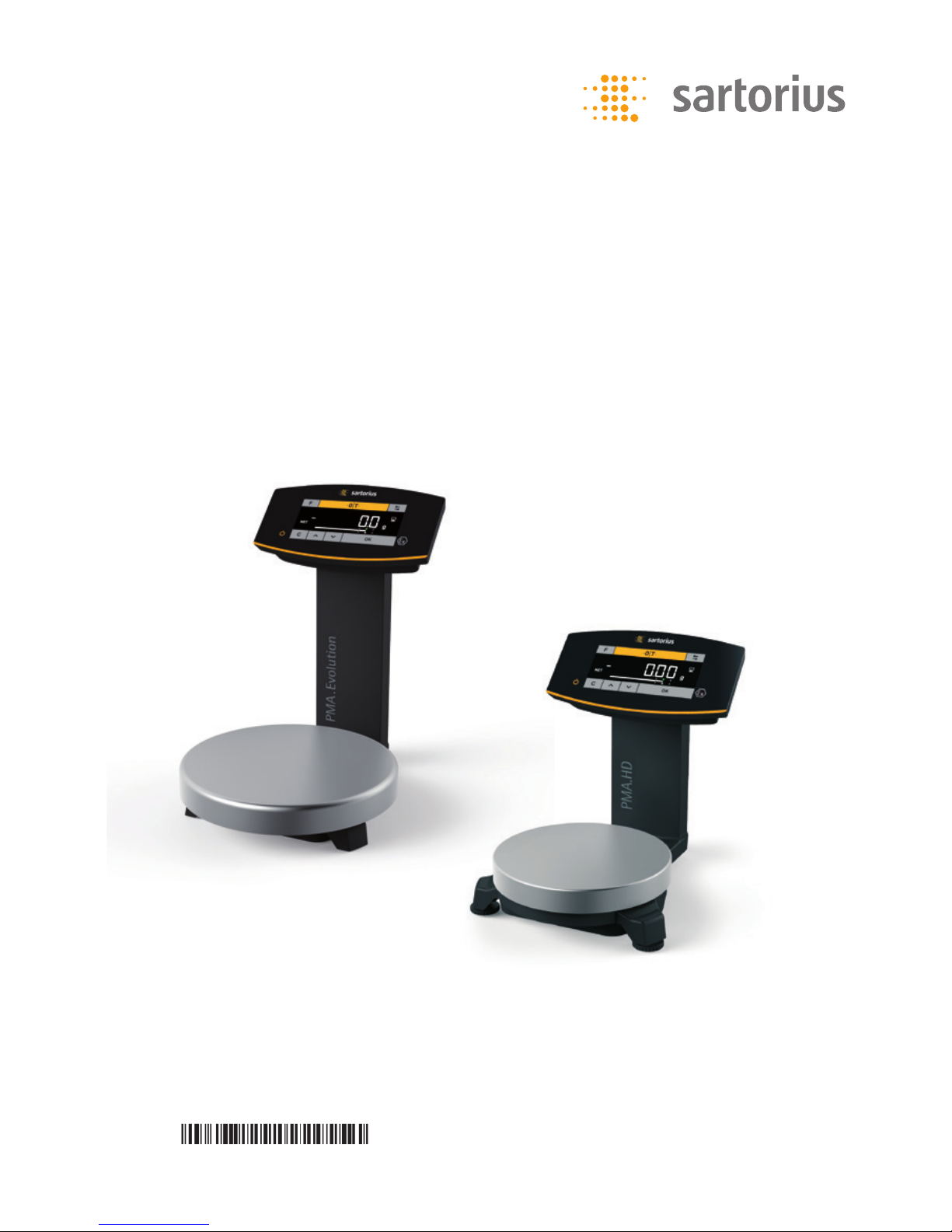
Operating Manual
PMA.Evolution | PMA.HD
EVO1X | LAB1X
Paint-mixing Scales for Use in Potentially Explosive Atmospheres
98648-020-50


Operating Manual EVO1X | LAB1X 3
Contents
Contents
1 About This Document.......................................4
1.1 Scope....................................................4
1.2 Symbols Used ...........................................4
1.3 User Information........................................4
2 Safety
........................................................5
2.1 General Safety Instructions.............................5
2.2 Installation Instructions ................................6
2.3 Intended Use............................................7
3 Device Overview
.............................................8
3.1 Front View ..............................................8
3.2 Rear View ...............................................9
3.3 Ex-link Converter/AC Adapter .........................10
3.4 Operating and Display Elements.......................11
3.5 Menu List ..............................................13
4 Installation
.................................................17
4.1 Unpacking and Equipment Supplied...................17
4.2 Selecting a Setup Location ............................17
4.3 Installing the Scale.....................................18
4.4 Supply Voltage.........................................18
4.4.1 AC Adapter Assembly (Optional) ..............18
4.4.2 Connecting the Scale..........................20
4.5 Anti-theft Locking Device .............................22
5 Commissioning
.............................................23
5.1 Leveling ................................................23
5.2 Warm-up Time.........................................23
6 Operation
...................................................24
6.1 Switching the Device On/Off ..........................24
6.2 Locking the Keypad/Weight Display ...................24
6.3 Zeroing/Taring .........................................24
6.4 Calibration/Adjustment................................24
6.4.1 Calibration.....................................25
6.5 Weighing...............................................25
6.5.1 Weighing with One Decimal Place ............25
6.5.2 Weighing with Two Decimal Places
(Not for Verified Models)......................26
6.6 Applications............................................26
6.6.1 Calculation by a Factor........................26
6.6.2 Weighing Using the Recalculation Function ..27
6.7 Menu Settings .........................................29
6.7.1 Accessing the SETUP Menu....................29
6.7.2 Configuring the Main Menu Settings . . . . . . . . .29
7 Care and Maintenance
....................................33
7.1 Cleaning................................................33
7.2 Maintenance ...........................................33
8 Malfunctions
...............................................34
9 Storage
.....................................................35
10 Disposal
. . . . . . . . . . . . . . . . . . . . . . . . . . . . . . . . . . . . . . . . . . . . . . . . . . . . .35
11 Serial Number Coding
.....................................36
12 Technical Data
..............................................37
12.1 General Data ...........................................37
12.2 Model-specific Data ...................................38
12.3 Verified Models with EC Type Approval Certificate:
Model-specific Technical Data.........................38
12.4 Device Dimensions .....................................39
12.4.1 Model EVO1X . . . . . . . . . . . . . . . . . . . . . . . . . . . . . . . . . .39
12.4.2 Model LAB1X ..................................39
12.5 USB Port (PC Connection) .............................39
12.5.1 Purpose ........................................39
12.5.2 Installing the Software Driver.................40
13 Accessories
..................................................41
14 Sartorius Service
. . . . . . . . . . . . . . . . . . . . . . . . . . . . . . . . . . . . . . . . . . .42
15 Conformity & Licenses
.....................................42
15.1 EU Declaration of Conformity .........................42
4 Operating Manual EVO1X | LAB1X
About This Document
1 About This Document
1.1 Scope
This operating manual applies to paint-mixing scale models:
− EVO1X
− LAB1X
1.2 Symbols Used
Denoting instructions and direct hazard warnings, all especially important
statements to be observed in these installation instructions will be marked as
follows:
This symbol denotes a possible danger with medium risk of death or (severe) injury
if not avoided.
This symbol denotes a possible danger with a low risk of moderate or minor injury
if not avoided.
This symbol denotes a danger with low risk that could result in property damage
if not avoided.
This symbol
− is an indication of a function or setting on the device
− is an indication that caution should be exercised while working
− identifies useful information.
This symbol provides information for the sale of scales verified for use in legal
metrology.
In the following, the term “verified” is used to mean “verified for use in legal
metrology” or “conformity-assessed.”
The following symbols are also used:
− Text that follows this symbol is a list.
t Text that follows this symbol describes activities which are to be performed in
the specified order.
y Text that follows this symbol describes the result of an action.
1.3 User Information
The illustrations in these instructions are based on the PMA.Evolution (EVO1X) model.
Operating Manual EVO1X | LAB1X 5
Safety
2 Safety
2.1 General Safety Instructions
− The scale and the ex-link converter meet the relevant legal provisions and
applicable standards (see the corresponding certificates in Chapter 15,
page 42).
− Nevertheless, improper use or handling can result in damage and/or injury.
Any improper use or operation of the scale or of the ex-link converter, i.e., that is
not consistent with the instructions, will result in forfeiture of all claims under
the manufacturer's warranty.
− Personnel need to have read and understood these installation instructions,
including the safety instructions.
− In the event of use in systems and under ambient conditions with higher safety
requirements, you must observe the requirements and provisions applicable in
your country.
− Always keep the equipment and scale freely accessible.
Ensure that the voltage rating printed on the AC adapter (optional) is identical to
your local mains voltage.
The IP protection rating of the scale and the ex-link converter YCO14-Z/YCO14-Y is
IP40 as per EN 60529. The devices must be handled carefully according to the IP
protection rating. The environment must be suitably secured.
Use within the scope of validity of the European ATEX Directive:
− In accordance with Directive 2014/34/EU, the model in the EVO1X | LAB1X series
is a category 2 device, suitable for use in Zone 1 potentially explosive areas.
− The ex-link converter YCO14-Z is only suitable for installation as an associated
electrical apparatus with the following ID code outside of the potentially
explosive area.
− The ex-link converter YCO14-Y is an associated electrical apparatus that can be
used in Zone 2.
− Refer to the EU Type Examination Certificates in Chapter 15, page 42 for the
device ID codes. Please observe the safety instructions in drawing 2023040 in
Chapter 15, page 42.
Use in Canada and the USA:
The intrinsically safe scales in the EVO1X | LAB1X model series are suitable for use in
Class I, Division 1 and Class I, Zone 1. The ex-link converter YCO14-Y can be used in
Class I, Division 2 and Class I, Zone 2.
Please observe Certificates of Conformity FM16US0226X and FM16CA0124X as well
as Control Drawing 2021459 in Chapter 15, page 42.
Use in Australia/New Zealand:
Please observe IECEx Certificate of Conformity IECEx FME 14.0008X and Safety
Instructions 2023040 in Chapter 15, page 42.
6 Operating Manual EVO1X | LAB1X
Safety
2.2 Installation Instructions
Do not operate the scale if its housing, the ex-link converter, or the AC adapter
including all connections are damaged.
Immediately disconnect the damaged device from the power.
Do not expose the scale, the ex-link converter, the AC adapter, or the accessories
supplied by Sartorius to extreme temperatures, aggressive chemical vapors, moisture,
shocks, vibrations, or strong electromagnetic fields. Observe the conditions of
operation described in the Specifications.
The connection cables between the devices as well as the casing on the wires inside
the device housing are made of PVC. Chemicals that corrode this material must be
kept away from these cables.
The operator shall be solely responsible for any modifications to the equipment and
for connecting any cables or equipment not supplied by Sartorius. Information on
operational quality is available upon request from Sartorius.
Only use original Sartorius accessories!
Note the IP protection rating of the scale, the ex-link converter, and the AC adapter.
Do not allow liquid penetration. The protection rating specifies the suitability of
equipment for various environmental conditions (moisture, foreign bodies).
Before cleaning the AC adapter, ex-link converter, or the scale:
Disconnect all devices from the power supply.
The scale and ex-link converter may only be opened by personnel trained by
Sartorius with the power disconnected.
Do not open the AC adapter.
Avoid generating static electricity on the glass panel of the touch screen and plastic
casing. The equipotential bonding conductor of the devices must be connected
properly, according to commonly accepted technical standards.
Only clean the device as stipulated in the cleaning instructions.
Take care that the glass panel of the touch screen is not damaged (e.g., by falling
objects, impact, or extreme pressure).
If the glass panel is damaged, disconnect the device from the power supply
immediately.
The surface of the touch screen should not be touched with pointed, sharp, hard, or
rough objects. You should only use the touch pen provided or your fingertips. Do not
use parts of clothing (e.g., sleeves) or sponges for cleaning because these can scratch
the surface (e.g., due to rivets or buttons in the sleeve, or sand in the sponge).
The device must be protected from unnecessarily extreme temperatures, aggressive
chemical vapors, moisture, shocks, and vibrations. Note the connection data (see
EC Type Examination Certificates for the device and/or the safety instructions,
drawing no. 2023040).
Operating Manual EVO1X | LAB1X 7
Safety
Warnings Concerning Installation and Operation:
The equipment must only be used indoors. Avoid generating static electricity on glass
and plastic parts. Connect the scale and the ex-link converter to the equipotential
bonding conductor using a suitable low-resistance method. All electrical circuits are
grounded and electrically connected to the metal parts of the devices.
− The installation must be checked for correct function and safety by trained and
qualified personnel at appropriate intervals (e.g., checking the cables for
damage).
− Operating personnel must be trained to recognize faulty operating states and to
be able to initiate the necessary safety measures (e.g., disconnecting the ex-link
converter from the power supply).
Lay the cables where they pose no risk of causing someone to trip.
Danger of Scale Damage!
Never close a paint can using a hammer while it is still on the weighing pan.
When closing, place the paint can on a firm, stable surface.
Observe the additional safety precautions and hazard warnings in subsequent
chapters.
2.3 Intended Use
This scale is only intended for mixing colors and paints. The scale is connected
to the ex-link converter only using the link cable supplied. The scale and ex-link
converter may only be used in potentially explosive areas in accordance with Safety
Instructions 2023040 in Chapter 15, page 42. Appropriate containers must be used
for loading each type of material.
The scale can be operated via the keypad as a stand-alone device or using
application software (e.g., a paint-mixing program from a paint manufacturer)
installed on a connected PC. The PC is connected to the ex-link converter via a
USB cable.
8 Operating Manual EVO1X | LAB1X
Device Overview
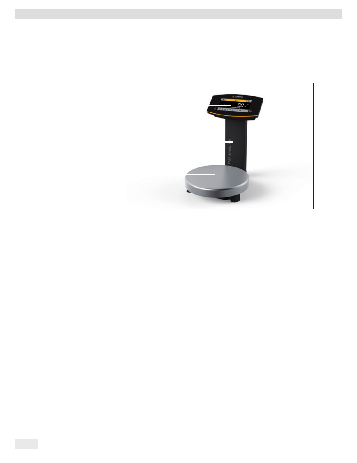
3 Device Overview
3.1 Front View
3
2
1
Item Designation
1 Operating and display elements (see also Chapter 3.4, page 11)
2 Support column
3 Weighing pan

Operating Manual EVO1X | LAB1X 9
Device Overview
3.2 Rear View
4
3
2
67
1
2
8
9
5
8
10
Item Designation
1 RJ-45 socket for link cable
2 Cable holders
3 Support column
4 Link cable (blue)
5 Ex-link converter
6 Anti-theft locking device
7 Grounding terminal for equipotential bonding
8 Leveling feet (PMA.HD and verified models only)
9 Leveling (PMA.HD and verified models only)
10 Menu access switch
10 Operating Manual EVO1X | LAB1X
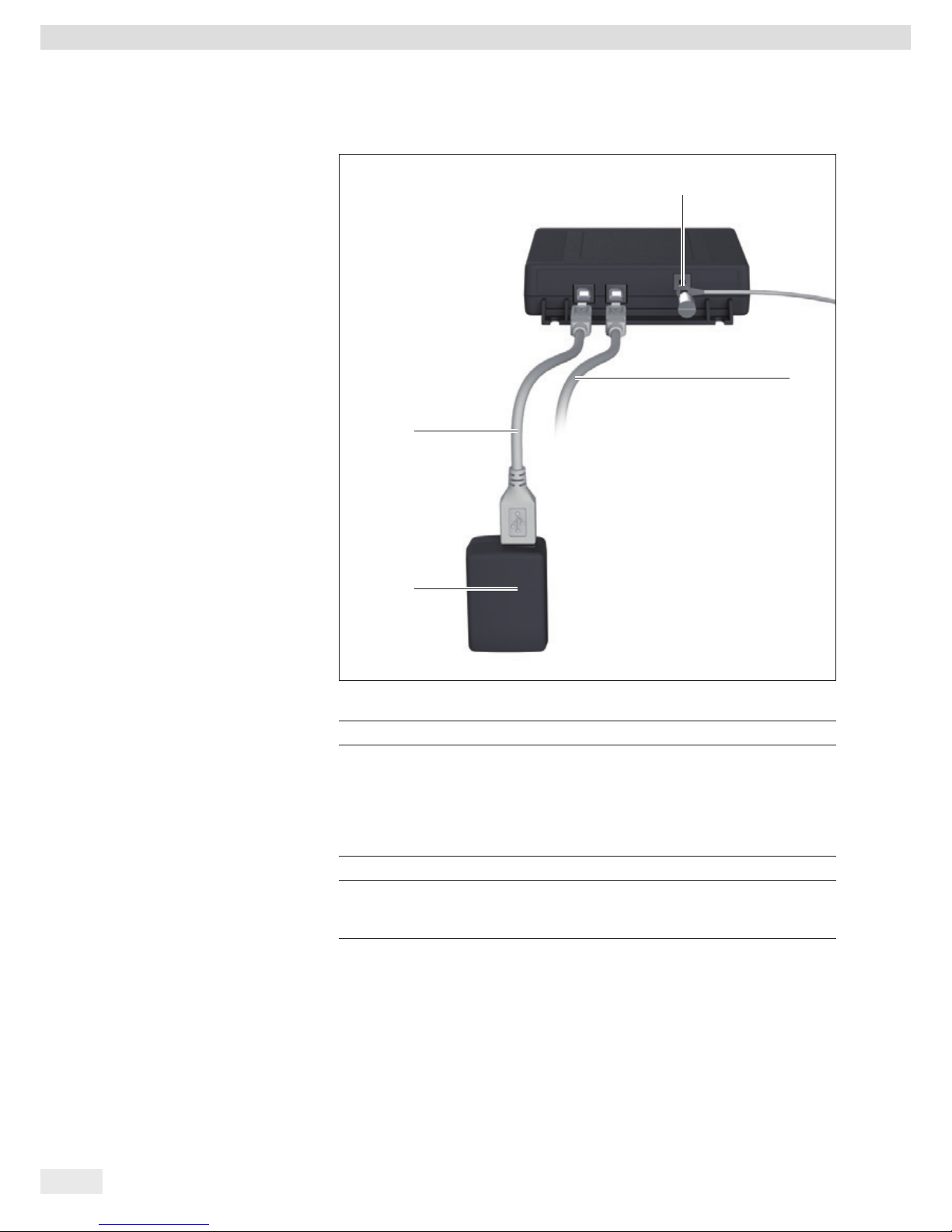
Device Overview
3.3 Ex-link Converter/AC Adapter
3
4
2
1
Item Designation
1 Grounding terminal for equipotential bonding
2 USB cable for connecting to PC or notebook. If the ex-link converter
YCO14-Y is in Zone 2 or Division 2 as per the Safety Instructions or Control
Drawing (Chapter 15, page 42) and the USB cable does not have an intrinsically safe electrical circuit with protection rating Ex ic or an NIFW electrical
circuit (for Division 2), the cable must be secured against disconnection
(see Chapter “4.4.2 Connecting the Scale,” page 20).
3 AC adapter (optional); only outside of the potentially explosive area
4 USB cable for power supply via the AC adapter (optional)
The AC adapter is only approved for the ex-link converter power supply if
the ex-link converter is installed outside of the potentially explosive area.
Operating Manual EVO1X | LAB1X 11
Device Overview
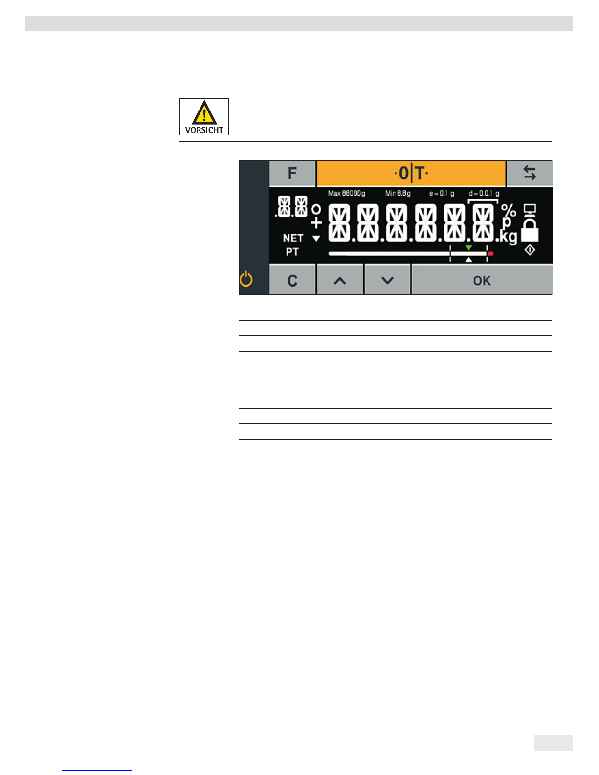
3.4 Operating and Display Elements
Sharp or pointed instruments (such as ballpoint pens) can damage the device!
− The touch screen should only be operated by lightly pressing it using the tips of
your fingers.
Key Function
$
Factor key for paint-mixing applications
&
Zeroing/taring
Z
Toggle key: Toggles the decimal places and/or unit
Depends on the menu setting
j
On/standby
§
Clear key/display of correction factor for paint-mixing applications
O
Up
P
Down
!
ENTER key/MEM key for paint-mixing applications
12 Operating Manual EVO1X | LAB1X
Device Overview
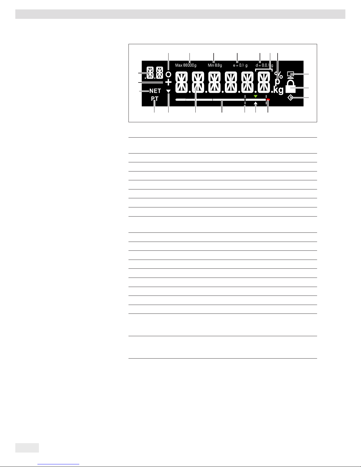
Item Function
1 Activated function in the menu list (see Chapter 3.5, page 13)
Symbols for zero range (verified models only)
2 Maximum weighing range
3 Minimum load Min (verified models only)
4 Verification scale intervals (verified models only)
5 Readability of the scale (scale interval d)
6 Weight unit and stability indicator
7 Communication with the PC
8 Activate “LOCK” function, or function activated
9
l symbol: Indicates that an internal process is in progress
For verified models: Indicates an invalid weight value
10 Tolerance range has been exceeded
11 Target value for bar graph
12 Tolerance range
13 Bar graph: Scaled display showing capacity usage (in percent)
14 Fourteen segment display
15 Trend display
16 Info on weight entry via application keypad (preset tare)
17 Net value
18 Plus (or minus) sign of the weight
19 Display:
− SETUP level
− Component/factor for paint-mixing applications
20
In verified mode for devices where e ≠ d: The frame indicates a scale
interval (standard scale interval d is smaller than verification scale
interval e)
19
18
17
16 15 14 13 12 10
7
8
9
11
1 2 3 4 5 20 6

Operating Manual EVO1X | LAB1X 13
Device Overview
3.5 Menu List
The “o” in the active column indicates the activated function in the respective menu.
Level 1 Level 2 Level 3 Active Level 4 Function CODE
SETUP
1.
| - - - -
SCALE
1.1
| | - - -
AMBIEN.
Installation site 1.1.1
| | |- - - -
V.STABL.
Very stable ambient conditions 1.1.1.1
| | |- - - - o
STABLE
Stable ambient conditions 1.1.1.2
| | |- - - -
UNSTAB.
Unstable ambient conditions 1.1.1.3
| | |- - - -
V.UNSTB.
Very unstable ambient conditions 1.1.1.4
| | - - -
FILTER
Application filter 1.1.2
| | |- - - -
FIN.RD.
Final readout 1.1.2.1
| | |- - - - o
FILL.WT.
Filling weight 1.1.2.2
| | - - -
STAB.RG.
Stability range/stability 1.1.3
| | |- - - -
1/2-DIG.
1/2 digit/good 1.1.3.2
| | |- - - -
1-DIG.
1 digit/normal 1.1.3.3
| | |- - - - o
2-DIG.
2 digits/sufficient 1.1.3.4
| | |- - - -
4-DIG.
4 digits/low 1.1.3.5
| | - - -
AUTOZ.
Automatic zero/drift correction 1.1.6
| | |- - - -
ON
On 1.1.6.1
| | |- - - - o
OFF
Off 1.1.6.2
| | - - -
WT.UNIT
Weight units 1.1.7
| | |- - - - o
GRAMS
Grams 1.1.7.2
| | |- - - -
PT.P.LB
Parts per pound
1
) 1.1.7.14
| | - - -
DSP.DEC.
Accuracy
1
) 1.1.8
| | |- - - - o
ALL
Show all decimal places 1.1.8.1
| | |- - - -
POLYR.
Multi-interval lab 1.1.8.13
| | - - -
CAL.ADJ.
Calibration/adjustment 1.1.9
| | |- - - - o
CAL.EXT.
External calibration/adjustment with default weight 1.1.9.1
| | |- - - -
LOCKED
CAL key/command locked 1.1.9.10
|
APP.PRG.
1.3
| | - - -
UNIT 2
2nd unit
1
) 1.3.1
| | |- - - - o
GRAMS
Grams 1.3.1.2
| | |- - - -
PT.P.LB
Parts per pound 1.3.1.14
| | - - -
DEC 2
Accuracy 2nd unit
1
) 1.3.2
| | |- - - -
ALL
Show all decimal places 1.3.2.1
| | |- - - - o
POLYR.
Multi-interval lab 1.3.2.13
| | - - -
TOGGLE
Toggle key on/off
1
) 1.3.3
| |- - - - o
OFF
Toggle key off 1.3.3.1
| |- - - -
ON
Toggle key on 1.3.3.2
|
Continued on next page
1
) Not available on scales verified for use in legal metrology

14 Operating Manual EVO1X | LAB1X
Device Overview
Level 1 Level 2 Level 3 Active Level 4 Function CODE
(SETUP)
| - - -
REC.MOD.
Recalculation 1.3.4
| | |- - - - o
TOTAL
Gross weight 1.3.4.1
| | |- - - -
INDIV.
Individual 1.3.4.2
|
GEN.SRV.
1.9
| | - - -
MEN.RES.
Menu reset 1.9.1
| | |- - - -
DEFAUL.
Load default menu 1.9.1.1
| | |- - - - o
NO
Stand-by 1.9.1.2
| |
DEVICE
2.
| - - - -
EXTRAS
2.1
| | - - -
MENU
Menu 2.1.1
| | | - - - - o
ENABLE
Menu can be edited 2.1.1.1
| | | - - - -
RD.ONLY.
Menu read only 2.1.1.2
| | - - -
KEYS
Key function enabled/locked 2.1.3
| | | - - - - o
ENABLE
Keypad enabled 2.1.3.1
| | | - - - -
LOCKED
Keypad locked 2.1.3.2
| | - - -
BACKLT.
Background light 2.1.4
| | | - - - -
10 PCT.
2.1.4.1
| | | - - - -
20 PCT.
2.1.4.2
| | | - - - -
30 PCT.
2.1.4.3
| | | - - - -
40 PCT.
2.1.4.4
| | | - - - -
50 PCT.
2.1.4.5
| | | - - - -
60 PCT.
2.1.4.6
| | | - - - - o
70 PCT.
2.1.4.7
| | |- - - -
80 PCT.
2.1.4.8
| | | - - - -
90 PCT.
2.1.4.9
| | | - - - -
100 PCT.
2.1.4.10
| | - - -
BARGR.
Bar graph on/off 2.1.5
| | |- - - -
OFF
Display without bar graph 2.1.5.1
| | |- - - - o
ON
Display with bar graph 2.1.5.2
| | - - -
ON.MODE
Switch-on behavior 2.1.6
| | |- - - - o
ON/STB.
On/standby 2.1.6.3
| | |- - - -
AUTO.ON
Automatic on 2.1.6.4
| | - - -
LOCK
Lock weight display 2.1.9
| | |- - - - o
OFF
Display on 2.1.9.1
| | |- - - -
ON
Display off 2.1.9.2
| | - - -
BAR.MOD
Bar graph mode 2.1.10
| | | - - - - o
NORMAL
Normal width 2.1.10.1
| | | - - - -
WIDE
Extra wide 2.1.10.2
| |
Continued on next page

Operating Manual EVO1X | LAB1X 15
Device Overview
Level 1 Level 2 Level 3 Active Level 4 Function CODE
(DEVICE) INTERF.
2.2
| | - - -
PROT.
Data transfer protocol 2.2.1
| | |- - - - o
SBI
SBI protocol 2.2.1.1
| | |- - - -
XBPI
XBPI protocol 2.2.1.2
| | - - -
BAUD
Baud rate 2.2.2
| | |- - - -
600
600 baud 2.2.2.3
| | |- - - -
1200
1200 baud 2.2.2.4
| | |- - - - o
2400
2400 baud 2.2.2.5
| | |- - - -
4800
4800 baud 2.2.2.6
| | |- - - -
9600
9600 baud 2.2.2.7
| | |- - - -
19200
19200 baud 2.2.2.8
| | |- - - -
38400
38400 baud 2.2.2.9
| | |- - - -
57600
57600 baud 2.2.2.10
| | - - -
PARITY
Parity bit 2.2.3
| | |- - - - o
ODD
Odd 2.2.3.3
| | |- - - -
EVEN
Even 2.2.3.4
| | |- - - -
NONE
No parity check 2.2.3.5
| | - - -
STOPBT.
Number of stop bits 2.2.4
| | |- - - - o
1 BIT
2.2.4.1
| | |- - - -
2 BITS
2.2.4.2
| | - - -
HANDSH.
Type of handshake 2.2.5
| | |- - - -
SOFTW.
Software handshake (X-On/X-Off) 2.2.5.1
| | |- - - -
HARDW.
Hardware handshake (RTS/CTS) 2.2.5.2
| | |- - - - o
NONE
No handshake 2.2.5.3
| | - - -
DATABT.
Number of data bits 2.2.6
| |- - - - o
7 BITS
7 data bits 2.2.6.1
| |- - - -
8 BITS
8 data bits 2.2.6.2
COMMUN.
Communication parameters 3.
| - - - -
SBI
SBI communication parameter 3.1
| | - - -
MAN.AUT.
Output 3.1.1
| | | - - - -
MAN.W/O
Print individual value without stability 3.1.1.1
| | | - - - -
MAN.W/
Print individual value after stability 3.1.1.2
| | | - - - - o
AUT.W/O
Print automatically without stability 3.1.1.4
| | | - - - -
AUT.W/
Print automatically after stability 3.1.1.5
| |
| | - - -
CANCEL
Cancel automatic output 3.1.2
| | | - - - - o
OFF
Cancellation not possible 3.1.2.1
| | | - - - -
ON
Cancel by pressing Print key 3.1.2.2
| | - - -
FORMAT
3.1.3
| | | - - - - o
16 CHR.
3.1.3.1
| | | - - - -
22 CHR.
3.1.3.2
Continued on next page

16 Operating Manual EVO1X | LAB1X
Device Overview
Level 1 Level 2 Level 3 Active Level 4 Function CODE
INPUT
4.
| - - - -
PASSWD.
Password 4.1.
| | - - -
NEW PW
Change/enter password 4.1.1
|
INFO
Information 5.
| - - - -
VER.NO.
Version number (firmware) 5.1
| - - - -
SER.NO.
Serial number 5.2
| - - - -
MODEL
Model designation 5.3
| - - - -
TYPE
Name/type information 5.4
| - - - -
INTRO
Intro text (if available) 5.5
|
LANG.
Language selection 6.
| - - - -
D
German 6.1
| - - - -
UK/US
o English 6.2
| - - - -
F
French 6.4
| - - - -
I
Italian 6.5
| - - - -
E
Spanish 6.6
| - - - -
NL
Dutch 6.7
| - - - -
P/BR
Portuguese 6.8
| - - - -
PL
Polish 6.9
| - - - -
TR
Turkish 6.10
| - - - -
PYC
Russian/Cyrillic 6.11
| - - - -
SLO
Slovenian 6.12
| - - - -
SRB
Serbian 6.13
| - - - -
CODES
Number codes 6.25
Operating Manual EVO1X | LAB1X 17
Installation
4 Installation
4.1 Unpacking and Equipment Supplied
t Open the packaging, making sure to remove all parts carefully.
t After unpacking the device, check it immediately for any external damage.
t If you detect any damage, proceed as directed in Chapter “7 Care and
Maintenance,” page 33.
t Save the box and all parts of the packaging for any future transport. All cables
should be unplugged when transporting.
The following parts are included in the equipment supplied:
Model Name PMA.Evolution PMA.HD
Large weighing pan: d 233 mm
x –
Small weighing pan: d 180 mm
– x
USB cable x x
Ex-link converter x x
Potential equalization cable x x
Link cable from converter to scale x x
Installation instructions x x
4.2 Selecting a Setup Location
Select the right setup location:
− Set up the device on a stable, even surface that is not exposed to vibrations.
− Maintain free access to the device at all times.
Choose a location that is not subject to the following negative influences:
− Heat (heater or direct sunlight)
− Drafts from open windows, AC systems, and doors
− Extreme vibrations during weighing
− Heavy “traffic areas” (personnel)
Acclimatization
Condensation from humidity can form on the surfaces of a cold device when it
is brought into a warm area. You should therefore let a device that has been
disconnected from its power source acclimatize for approximately 2 hours before
reconnecting it to the supply voltage.
Seal on Scales Verified for Use in Legal Metrology:
Legislation requires that a seal be affixed to verified scales. On Sartorius devices, this
seal takes the form of a sticker with the “Sartorius” logo. If the seal is removed, the
validity of verification will become void and you must have your scale re-verified.
The verification supplied here is for verified weighing instruments for use in the EEA.
Please keep it in a safe place.
18 Operating Manual EVO1X | LAB1X
Installation
4.3 Installing the Scale
The scale must be disconnected from the power supply for all assembly work.
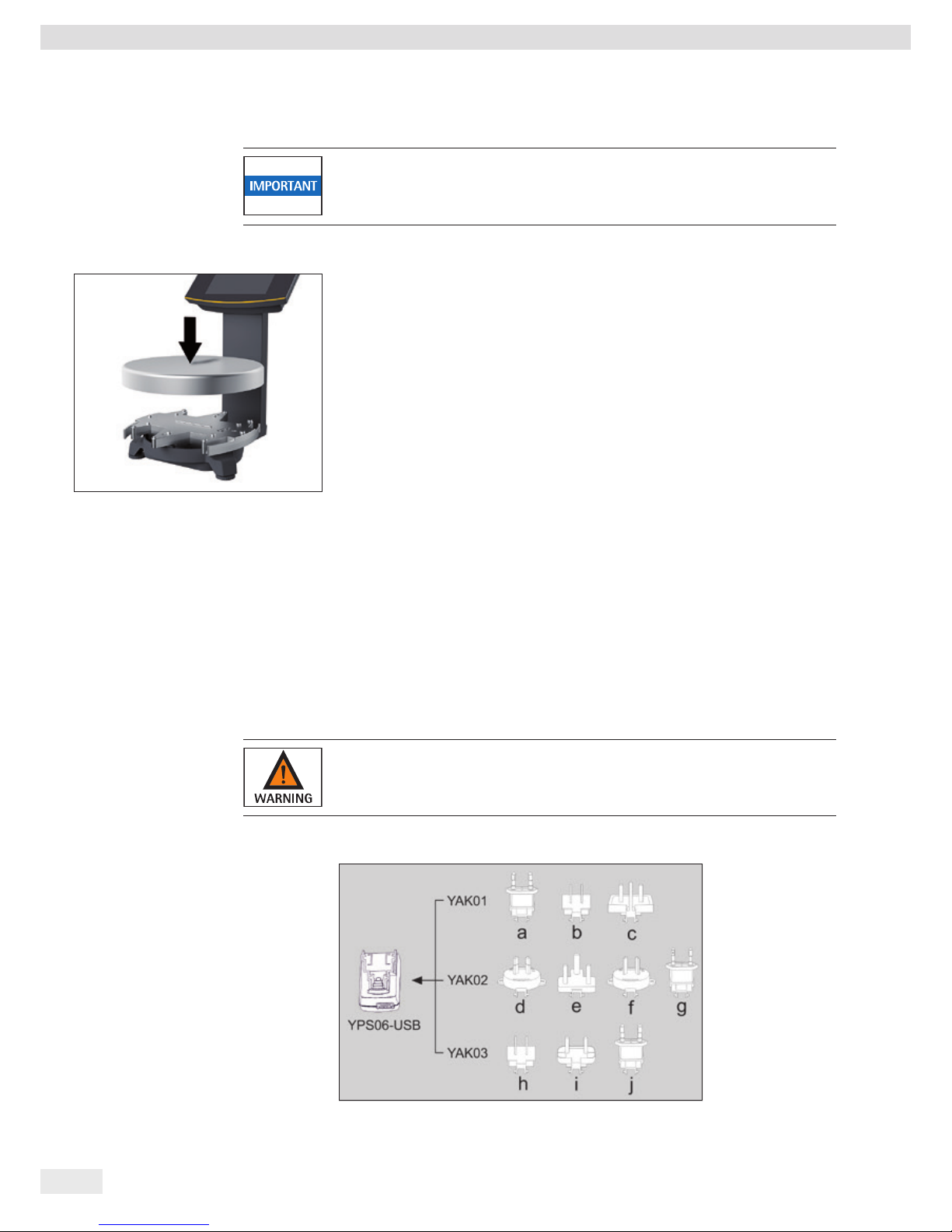
Placing the Weighing Pan onto the Scale
t Place the weighing pan onto the scale from above.
4.4 Supply Voltage
The scale is connected to the power supply via a PC/notebook or using the optional
AC adapter YPS06-USB (see Chapter “13 Accessories,” page 41), which is supplied
with mains adapters for use in various countries.
Power supply via the AC adapter is only required:
− When no PC or notebook is available.
− In exceptional cases, when the output power of the USB interface of the PC or
notebook is not sufficient.
The assembly is described in the following.
4.4.1 AC Adapter Assembly (Optional)
Using the wrong mains adapter may cause a fatal electric shock and damage
the equipment.
Never plug the mains adapter into the socket when it is disconnected from the
AC adapter (danger of electric shock).
t Use the right mains adapter for your mains power supply.
Operating Manual EVO1X | LAB1X 19
Installation
Mains Adapter Set YAK01
Bag Region/Country
a) transparent Europe/EU (except United Kingdom)
b) blue USA
c) yellow United Kingdom
Mains Adapter Set YAK02
d) red Australia
e) turquoise South Africa
f) white Argentina
g) pink Brazil
Mains Adapter Set YAK03
h) light brown China
i) black India
j) green Korea
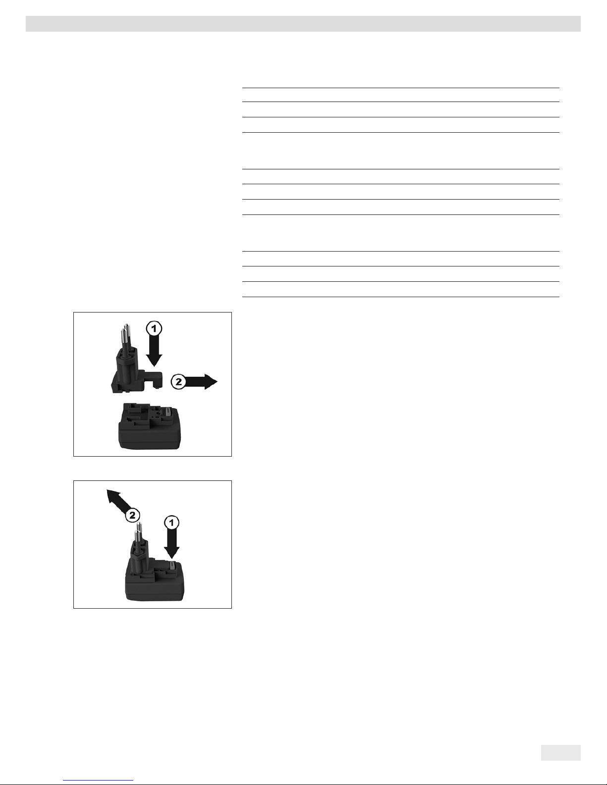
t Push (1) and slide (2) the mains adapter required for your power supply into the
opening of the AC adapter module.
When doing this, the mains adapter needs to lock into position.
Removing/Replacing the Mains Adapter
t Unlock (1) and then remove (2) the mains adapter.
Power Connection/Safety Precautions
− Only use original Sartorius AC adapters.
The AC adapter has an IP rating of IP40 in accordance with EN60529 / IEC60529.
− Make sure that the voltage rating printed on this unit matches the voltage at the
place of installation.
− If the stated supply voltage or the plug design of the AC adapter does not
comply with your country's standard then please inform your nearest Sartorius
representative.
− The power must be connected in accordance with the regulations applicable in
your country.

20 Operating Manual EVO1X | LAB1X
Installation
4.4.2 Connecting the Scale
Connecting the Scale
t Insert the link cable plug into the RJ-45 socket on the back of the display.
Laying the Link Cable
t Lay the link cable (blue) through the cable holders on the back of the scale.
t Connect the link cable to the ex-link converter.
Connecting the Grounding Cable
This explosion-protected system should be set up according to commonly accepted
technical standards. The applicable national electrical code and safety regulations for
your particular country must be observed.
Before commissioning the scale, a check must be carried out by or under the
supervision of a qualified electrician to ensure that the system is in good working
order.
Check whether or not the competent authorities (e.g., industrial supervisory board)
need to be informed. It is also necessary to carry out inspections of the system
during operation.
Inspection intervals should be such that any significant defects that may occur can
be identified in good time. Inspections should be carried out at least once every
three years. The applicable requirements and guidelines should also be observed
during operation.
Establish a low-resistance connection from the scale and the ex-link converter
YCO14-Z to a customer-supplied equipotential bonding conductor connection
via the equipotential bonding conductor connections (PA) on the device using a
suitable grounding cable with a gage of at least 4 mm
2
.
Installation must be carried out properly by trained personnel and according to
commonly accepted technical standards. The system should only be operated for
the first time when it is certain that the area is not potentially explosive.
Operating Manual EVO1X | LAB1X 21
Installation
If deviations are evident during startup due to transport damage (e.g., no display,
no backlighting), disconnect the scale from the power supply and contact Sartorius
Service.
Connect the scale to the equipotential bonding conductor using an equipotential
bonding cable with a gage of at least 4 mm².
t Connect the cable lug of the equipotential bonding cable to the grounding
terminal of the scale.
t Connect the equipotential bonding cable to the customer-supplied equipotential
bonding conductor.
Connect the ex-link converter to the equipotential bonding conductor using another
equipotential bonding cable with a gage of at least 4 mm².
t Connect the cable lug of the equipotential bonding cable to the grounding
terminal of the ex-link converter.
t Connect the equipotential bonding cable to the customer-supplied equipotential
bonding conductor.
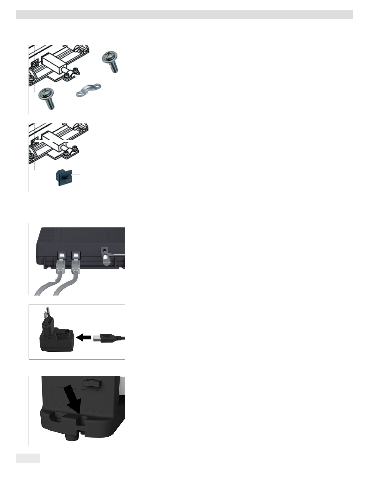
Connecting a PC/Notebook
t Insert a USB cable (1) into the right-hand socket on the ex-link converter and
connect the cable to a PC or notebook. If the ex-link converter YCO-Y is being
used and installed in Zone 2 or Division 2 potentially explosive areas and the
USB cable (1) does not have an intrinsically safe electrical circuit, the cable must
be secured against disconnection. Refer to the Control Drawing and Safety
Instructions (Chapter 15, page 42) as well as the following illustrations.
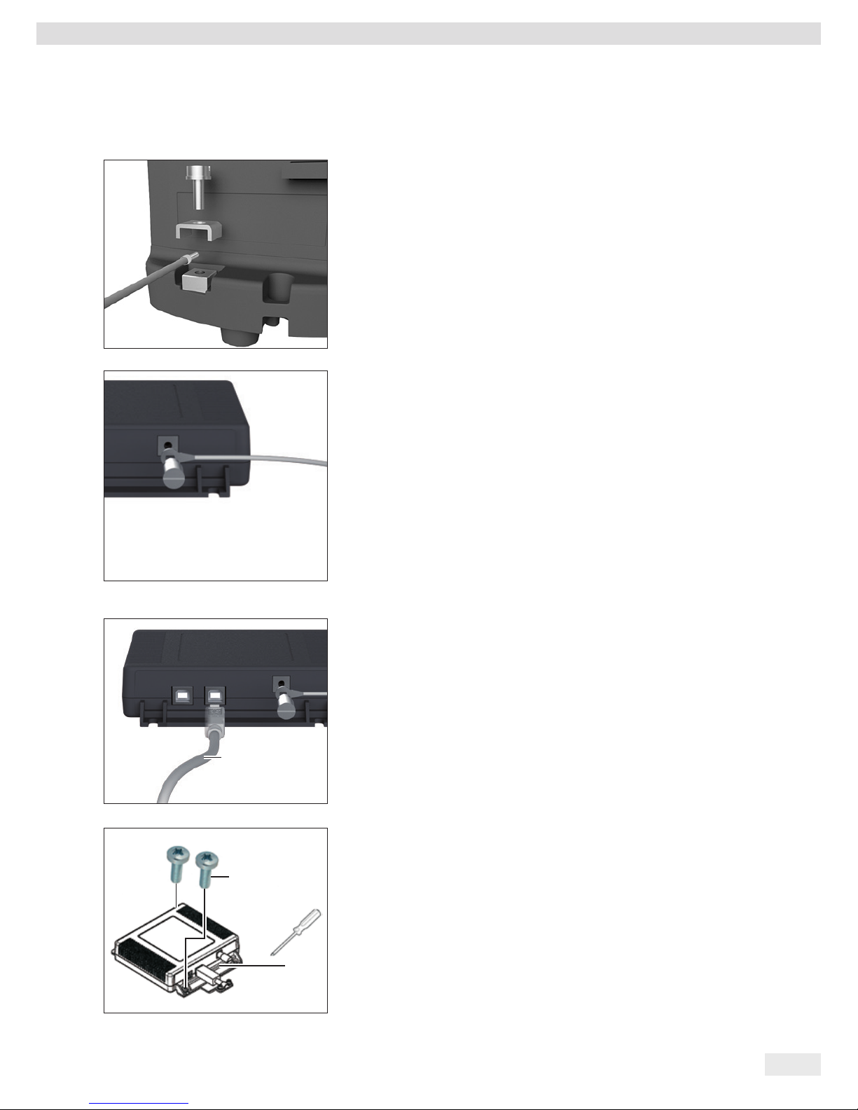
t Fasten the strain relief YSR01 to the converter (1) using the two screws (2).
1
1
2
2
22 Operating Manual EVO1X | LAB1X
Installation
t Attach the USB cable to the strain relief (3) using the clamp (1) and the two
screws (2).
t Use the protective cap (2) to seal up the left-hand USB port (1).
Connecting the AC Adapter (Optional); not for YCO14-Y when Installed in
Zone 2 or Division 2 Potentially Explosive Areas
t Insert an additional USB cable (2) into the ex-link converter.
t Insert the USB cable into the YPS06-USB AC adapter.
t Plug the AC adapter into a wall outlet (supply voltage).
t Insert the USB cable into the YPS06-USB AC adapter.
t Plug the AC adapter into a wall outlet (supply voltage).
4.5 Anti-theft Locking Device
t If required, secure the scale at the back.
2
1
2
3
2
1
2

Operating Manual EVO1X | LAB1X 23
Commissioning
5 Commissioning
5.1 Leveling
Leveling for PMA.HD and Verified Models
Leveling the scale compensates for slant or unevenness at the place of installation.
The scale must be perfectly horizontal to ensure consistent, reproducible weighing
results.
The scale needs to be re-leveled and then adjusted each time its setup location is
changed.
t Turn the two leveling feet as shown in the illustration until the air bubble is
centered within the circle of the level indicator.
− Air bubble at “12 o'clock:” Turn both feet clockwise.
− Air bubble at “3 o'clock:” Turn the left foot clockwise and the right foot
counterclockwise.
− Air bubble at “6 o'clock:” Turn both feet counterclockwise.
− Air bubble at “9 o'clock:” Turn the left foot counterclockwise and the right
foot clockwise.
5.2 Warm-up Time
To ensure accurate results are delivered, the scale must warm up for at least
30 minutes after initial connection to the power supply. Only then will the device
have reached the required operating temperature.
Using a Scale Verified for Use in Legal Metrology:
− Ensure that there is a warm-up time of at least 24 hours after initial connection
to the power supply.
12*
9*
6*
* Clock
0
30

24 Operating Manual EVO1X | LAB1X
Operation
6 Operation
6.1 Switching the Device On/Off
Switching On
t Briefly press the j key (on/standby).
y An automatic self-test runs. This ends when the display shows 0.0 g.
t If another value is displayed: Set the scale to zero via the 0 key.
Switching Off
t Press and hold the j key for several seconds (on/standby).
y The scale switches to standby mode.
6.2 Locking the Keypad/Weight Display
Locking
t Briefly press the j key (on/standby) to lock the keypad and turn off the weight
display.
y The padlock symbol H flashes for several seconds.
t Press the padlock symbol H while flashing to activate the lock.
y The keypad/weight display is locked and the padlock symbol lights up continually.
Unlocking
t Press the padlock symbol H to deactivate the lock.
t Enter the password (if set) (see Chapter 6.7.2.6, page 31).
y The lock is deactivated.
6.3 Zeroing/Taring
t Briefly press the 0 key.
6.4 Calibration/Adjustment
The scale needs to be re-leveled and then adjusted each time its setup location is
changed.
Warm-up Time
To ensure accurate results are delivered, the scale must warm up for at least
30 minutes after initial connection to the power supply.
Only then will the device have reached the required operating temperature.
t Wait approx. 30 minutes after connecting the scale to the power supply before
adjusting the scale and weighing.
Using a Scale Verified for Use in Legal Metrology:
− Ensure that there is a warm-up time of at least 24 hours after initial connection
to the power supply.
0
30

Operating Manual EVO1X | LAB1X 25
Operation
6.4.1 Calibration
External Calibration/Adjustment for Verified Scales
Scales for use in legal metrology must be externally calibrated before being verified
at the location of use.
− When the scale is used in legal metrology, external calibration is locked as
follows:
− The menu access switch is locked
− The menu access switch cap is sealed
t Press the 0 key for approx. 2 seconds.
y The preset calibration weight appears in the display (e.g., 5000 g)
t If required, select a different calibration weight via the O / P keys.
t Confirm the displayed calibration weight via the ! key.
y CAL.EXT. appears on the display with the negative calibration weight.
t Center the calibration weight on the weighing pan.
y The calibration is performed. The calibration is complete when CAL.DON appears
in the display.
t Remove the calibration weight from the weighing pan.
6.5 Weighing
Using a Verified Balance in Legal Metrology:
The Type-Approval Certificate for verified scales is only valid for non-automatic
weighing instruments. For automatic operation with or without additional integrated
equipment, please follow the applicable national regulations for the installation
location.
− The temperature range (°C) listed on the ID label should not be exceeded during
operation.
Example:
K +10–+30°C
6.5.1 Weighing with One Decimal Place
t Place the empty paint can on the weighing pan.
t Briefly press the 0 key to zero.
y The display shows “0.0 g.”
t Add the first component “484.8 g.”
t Read off the weight when the stability symbol (in this example) “g” is displayed.
t Add the other components until the desired weight (formula) is reached.
t Remove the filled paint can from the weighing pan.
Danger of Scale Damage!
Never close a paint can using a hammer while it is still on the weighing pan.
t When closing the paint can, place it on a firm, stable surface.
0.0
484.8
840.2
1218.8
1230.0

26 Operating Manual EVO1X | LAB1X
Operation
6.5.2 Weighing with Two Decimal Places (Not for Verified Models)
A menu setting is required for weighing with two decimal places (see
Chapter “6.7.2.4 Activating the Toggle Key (Not for Verified Models),” page 30).
t Place the empty paint can on the weighing pan.
t Briefly press the 0 key to zero.
y The display shows “0.0 g.”
t Press the toggle key Z.
y The display shows “0.00 g.”
t Add the first component “205.50 g.”
t Read off the weight when the stability symbol (in this example) “g” is displayed.
t Add the other components until the desired weight (formula) is reached.
t Remove the filled paint can from the weighing pan.
When the scale is tared and the second decimal place with a resolution of 0.05 g is
activated via the toggle key Z, weighing up to 999.95 g with two decimal places
can be performed.
Values over 999.95 g can only be weighed using one decimal place.
Danger of Scale Damage!
Never close a paint can using a hammer while it is still on the weighing pan.
t When closing the paint can, place it on a firm, stable surface.
6.6 Applications
Note for Scales for Use in Legal Metrology:
All application programs can be selected on scales verified for use in legal metrology.
Computed values can be marked using the following characters:
− Percent = %
− Computed values = o, l symbol
6.6.1 Calculation by a Factor
This function enables you to weigh in amounts that are smaller or larger than that
of your basic formula for a specific paint color (e.g., 250 ml of a 1 l formula).
The factors (amounts) can be set via the factor key $ and O / P in a range of
0.1 to 6.0.
The following factors can be set directly via the factor key $:
0.25 0.5 0.75 1.0 1.5 2.0 2.5 3.0 3.5 4.0 4.5 5.0.
Using the keys O (up) and P (down), the factor can be changed
− in the range 0.10 to 1.0 in increments of 0.01
− in the range 1.0 to 6.0 in increments of 0.1
0.0
0.00
205.50
213.50
593.85
1414.2

Operating Manual EVO1X | LAB1X 27
Operation
Factor Calculation Example
As you add the components of your formula, the weight is displayed in “g.”
For models verified for use in legal metrology, the displayed value is marked with
a l symbol to indicate computed values.
Suppose you want to weigh 250 ml for a basic formula that has a total of 1 l, and
you don't want to have to manually recalculate the individual components of the
formula.
The basic formula for 1 liter:
250 g 1st component
+ 250 g 2nd component
+ 500 g 3rd component
Total: 1000 g
t Place the empty container on the weighing pan.
t Briefly press the 0 key to tare.
t Press the factor key $ several times until the factor “.25” is displayed below the
factor key.
t Slowly add the first component “250 g” of the formula until the display shows
“250 g.”
t Add the second color component “250 g” until the display shows “500 g.”
t Add the third component “500 g” until the display shows “1000 g.”
This concludes the calculation example. According to the display, exactly 1000 g was
poured in, but the container actually only contains 250 g by weight in accordance
with the factor you selected.
The procedure is the same for any other conversion factor.
6.6.2 Weighing Using the Recalculation Function
Let's suppose that you poured in too much of one color component for a given
formula (in this example, a 4-component recipe).
This example further assumes that you previously poured in all of the other amounts
exactly according to each of the values you entered and saved them by pressing the
MEM key !.
t Press the P key to start the recalculation program.
y “C” flashes on the display.
t Correct the value using the O / P keys to match the specified formula value.
t Press the MEM key !.
y The scale automatically calculates the amount to be added for each of the
components that were already poured in. The display shows the amounts required
to correct the formula up to the point at which the overpour occurred.
t After the correction has been completed, you can continue filling the remaining
components.
You can correct overpours as often as needed, as long as the total weight of the
formula does not exceed the scale's maximum weight.
Keep in mind that the total quantity of paint (liter) at the conclusion of filling
increases each time you correct a component. Press the § key to display the
correction factor of the fill quantity. “C” = correction factor
0.0
250.0
500.0
1000.0
.25
.25
.25
.25

28 Operating Manual EVO1X | LAB1X
Operation
Recalculation Example (Gross Weight)
For models verified for use in legal metrology, the displayed value is marked with a
l symbol to indicate computed values.
t Place the empty container on the weighing pan.
y The scale shows the weight of the empty paint can.
t Briefly press the 0 key to tare.
t Slowly add the first component (50 g) of the formula until the display shows
“50 g.”
t Briefly press the ! key to save the value.
y “STO 01” appears on the display, the first value is saved.
y ”02” appears in the top left of the display (second color component).
t Add the second color component (60 g) until the display shows “110 g.”
t Briefly press the ! key to save the value.
y “STO 02” appears on the display, the second value is saved.
y “03” appears in the top left of the display (third color component).
t Add the third color component (90 g) until the display shows “200 g.”
Oops! You poured in too much (203 g). The correct value for the formula is
200.0 g.
t Press the P key.
y The recalculation is started. “c” flashes in the top left of the display.
t Press the P key until the correct weight value “200 g” is displayed.
t Briefly press the ! key to confirm the corrected value.
y ”C0R 01” flashes briefly on the display (correction of the first color component).
y ”C1” appears in the top left of the display with the weight value to be corrected
“- 1.7 g.”
t Add 1.7 g of the first color component until the display shows “0.0 g” or the bar
graph stops below the green arrow.
t Confirm the correction for the first color component by pressing the ! key.
y ”C0R 02” flashes briefly on the display (correction of the second color
component).
y ”C2” appears in the top left of the display with the weight value to be corrected
“- 2.0 g.”
t Add 2.0 g of the second color component until the display shows “0.0 g” or the
bar graph stops below the green arrow.
y ”STO 02” appears on the display, the second (corrected) value is saved.
y You are automatically returned to the formulation program.
y ”04” appears in the top left of the display (fourth color component).
t Press the § key to check the amount of the total weight.
y The correction factor “C 1.03” appears on the display for several seconds.
Total weight = weight of specified formula x correction factor.
y ”04” appears again in the top left of the display after the correction factor is
displayed (fourth color component).
t Add additional color components of the formula as described above.
This concludes the calculation example.
118.0
0.0
50.0
STO 01
02
110.0
STO 02
03
203.0
200.0
C
COR 01
C1
1.7
C1
0.0
COR 02
C2
2.0
C2
0.0
STO 02
04
1000.0
C 1.03
04
1000.0

Operating Manual EVO1X | LAB1X 29
Operation
6.7 Menu Settings
6.7.1 Accessing the SETUP Menu
Accessing the SETUP menu and settings is described in the following using “Adapting
the scale to ambient conditions” as an example (SETUP -> SCALE -> AMBIEN.):
t Press the ! key for approx. 2 seconds.
y Level 1 of the SETUP menu is displayed.
t Select the SETUP menu item of the first level using the O / P keys.
t Press the ! key.
y Level 2 of the SETUP menu is displayed.
t Select the SCALE menu item of the second level using the O / P keys.
t Press the ! key.
y Level 3 of the SETUP menu is displayed.
t Select the AMBIEN. menu item of the third level using the O / P keys.
t Press the ! key.
y Level 4 of the SETUP menu is displayed.
t Select the desired setting using the O / P keys.
t Press the ! key.
y The setting is applied; “o” appears on the display.
(This concludes the example.)
t Press the § key several times to exit the menu.
A detailed list of possible settings can be found in Chapter “3.5 Menu List,”
page 13.
6.7.2 Configuring the Main Menu Settings
6.7.2.1 Accessing the Setup Menu
t Press and hold the ! key for approx. 2 sec.
y SETUP (level 1) appears on the display.

30 Operating Manual EVO1X | LAB1X
Operation
6.7.2.2 Language Setting
Level 1 Level 2
LANG.
t Press O, select LANG.
t Press !
D
o German
t Press O / P, select language
UK/US
English
t Press !, “o” appears.
F
French y The desired setting is applied.
I
Italian
t Press § several times to exit the menu
etc.
6.7.2.3 Standard Default Settings (0.1 g)/Polyrange (0.05 g/0.1 g) and Grams/Parts per Pound. (Not for Verified Models)
The default settings which are active when the scale is switched on can be found under “SETUP > SCALE > WT.UNIT” and “SETUP >
SCALE > DSP.DEC.:”
t Access the Setup menu (see Chapter 6.7.2.1, page 29).
Level 1 Level 2 Level 3 Level 4
SETUP
t Press !
| - - -
SCALE
t Press !
| - - -
WT.UNIT
Units
t Press O / P, e.g., select DSP.DEC.
| |- - - o
GRAMS
t Press !
| |- - -
PT.P.LB
t Press O / P, e.g., select ALL
| - - -
DSP.DEC.
Accuracy
t Press !, “o” appears
|- - - o
ALL
y The new code is set.
|- - -
POLYR.
t Press § several times to exit the menu
6.7.2.4 Activating the Toggle Key (Not for Verified Models)
When the toggle key Z is active, you can use it to toggle the unit between, e.g., grams, parts per pound, or the decimal place.
The unit and/or decimal place is toggled when the key is pressed:
t Access the Setup menu (see Chapter 6.7.2.1, page 29).
Level 1 Level 2 Level 3 Level 4
SETUP
t Press !
| - - -
APP.PRG.
t Press O / P, select APP.PRG.
| - - -
TOGGLE
t Press !
|- - - o
ON
t Press O / P, select ON
|- - -
OFF
t Press !, “o” appears.
y Toggle key Z is activated.
t Press § several times to exit the menu
Configuring the Toggle Key Z Function
Pressing the toggle key Z toggles the scale between the default settings (see Chapter 6.7.2.3, page 30) and settings defined in
“SETUP > APP.PRG. > UNIT” and “SETUP > APP.PRG. > DSP.DEC.”
t Access the Setup menu (see Chapter 6.7.2.1, page 29).

Operating Manual EVO1X | LAB1X 31
Operation
Level 1 Level 2 Level 3 Level 4
SETUP
t Press !
| - - -
APP.PRG.
t Press O / P, select APP.PRG.
| - - -
UNIT 2
t Press !, press O / P, select UNIT 2
| |- - - o
GRAMS
t Press !, press O / P, select setting (e.g., GRAMS)
| |- - -
PT.P.LB
t Press !, “o” appears indicating the desired setting is applied.
| - - -
DEC 2
t Press §
|- - -
ALL
t Press O / P, select DEC 2
|- - - o
POLYR.
t Press !, press O / P, select setting
t Press !, “o” appears indicating the desired setting is applied.
t Press § several times to exit the menu
6.7.2.5 Activating the “LOCK” Function
The “LOCK” function protects the scale from unauthorized use. When this function is active, the scale readout shows weight values
only when there is active communication between the scale and a connected PC. If communication is interrupted, the readout
goes blank and the display shows a padlock symbol. Activation of the LOCK function is configured under “EXTRAS.”
t Access the Setup menu (see Chapter 6.7.2.1, page 29).
Level 1 Level 2 Level 3 Level 4
DEVICE
t Press O / P, select DEVICE, press !
| - - -
EXTRAS
t Press O / P, select EXTRAS, press !
| - - -
LOCK
t Press O / P, select LOCK, press !
|- - - o
ON
t Press O / P, select ON
|- - -
OFF
t Press !, “o” appears,
y The “LOCK” function
is activated.
t Press § several times to exit the menu
6.7.2.6 Password Prompt
In addition to the “LOCK” function, you can also configure password protection for additional security.
With this feature, the “LOCK” function can only be deactivated by entering the password you configure.
Entering the Password
When the password prompt appears, the numbers 1 2 3 4 5 6 appear on the display.
You can switch to the numbers 7 8 9 0 and back again via the O / P keys.
t Enter the password by entering the individual numbers on the display.
y When you enter the correct password, the “LOCK” function will be deactivated.

32 Operating Manual EVO1X | LAB1X
Operation
Changing the Password
The password is numeric and can have up to 6 digits. Entering 6 spaces deletes the password, which deactivates the password
function. This restores the device to its original setting (scale is not password-protected).
t Access the Setup menu (see Chapter 6.7.2.1, page 29).
Level 1 Level 2 Level 3
INPUT
t Press O / P, select INPUT, press !
| - - -
PASSWD.
t Press O / P, select PASSWD., press !
| - - -
OLD PW
| - - | - - | - - | - - | - - | - - | - - -
y When an old password is active, OLD PW appears briefly so that you can enter the old password.
y The display shows: “_ _ _ _ _ _ .”
y The first line flashes.
t Make the following inputs:
− O / P keys: Selects numbers 0 to 9.
− §: Go back to the previous number.
− !: Confirm entry or go to the next number.
t Repeat to enter the remaining numbers.
y If you make an incorrect entry, NOT OK appears. Press ! and reenter the old password.
NEW PW y When you make a correct entry, NEW PW appears briefly so that you can enter the new pass-
word.
y The display shows: “_ _ _ _ _ _ .”
y The first line flashes.
t Make the following inputs:
− O / P keys: Selects numbers 0 to 9.
− §: Go back to the previous number.
− You can enter spaces to delete the number/password.
− !: Confirm entry or go to the next number.
t Repeat to enter the remaining numbers.
y The password has been changed.
t Press § several times to exit the menu.
6.7.2.7 Resetting the Scale: “RESET”
If required, you can restore the scale to its factory settings.
Note:
If you have activated the password function, this feature is password-protected.
t Access the Setup menu (see Chapter 6.7.2.1, page 29).
Level 1 Level 2 Level 3 Level 4
SETUP
t Press O / P, select SETUP, press !
| - - -
GEN.SRV.
t Press O / P, select GEN.SRV., press !
| - - -
MEN.RES.
t Press O / P, select MEN.RES., press !
|- - -
DEFAUL.
t Press O / P, select DEFAUL.
|- - - o
NO
t Press !, “o” appears,
y The factory settings are loaded.
t Press § several times to exit the menu

Operating Manual EVO1X | LAB1X 33
Care and Maintenance
7 Care and Maintenance
7.1 Cleaning
Electrical Hazard from Voltage or Current
Disconnect the AC adapter (if connected) from the mains. Unplug any connected
data cables from the ex-link converter. Never open the scale, the AC adapter, or
the ex-link converter. The parts contained in these cannot be cleaned, repaired or
replaced by the user.
− Make sure that no liquid or dust gets into the scale, the AC adapter, or the
ex-link converter.
− Only use soft brushes and cloths for cleaning.
− Never use cleaning accessories or agents that contain abrasive components or
ingredients (e.g., scouring cream, steel wool),
which can ultimately damage the equipment.
Do not clean the following parts with acetone or aggressive cleaning agents:
mains socket, data interface, labels, and all other plastic parts.
Cleaning the Control Panel
t Turn off the device before cleaning the control panel since touching the screen
could trigger unwanted inputs.
Cleaning the Device Housing
t Clean the device.
t Use a soft cloth to dry the device.
7.2 Maintenance
Electrical Hazard from Voltage or Current
Repair work on the (optional) AC adapter must only be carried out by trained service
technicians. Contact Sartorius Service for professional repairs (see Chapter 15.1,
page 42).
To ensure the continued accuracy of your scale, we recommend scheduling regular
servicing at least once a year.
Sartorius Service offers different service contracts with maintenance intervals that
are tailored to your needs.
A calibration certificate should always be issued as part of every maintenance
session.
Safety inspections of the AC adapter and its connections must be performed at
appropriate intervals by a qualified electrician (e.g., every 2 years).

34 Operating Manual EVO1X | LAB1X
Malfunctions
8 Malfunctions
Problem Cause Remedy
No segments appear
on the weight display
− No AC power is available − Check power supply
The weight readout
shows “LOW”
− No weighing pan on the
scale
− Position the weighing
pan
The weight readout
shows “HIGH”
− Weighing capacity
exceeded
− Unload the scale
The weight readout
changes constantly
− Unstable ambient
conditions
− Excessive vibration or
draft
− Weighing pan is being
affected at some point
by outside influences
− Set up scale in
another area
− Adjust the scale
settings (see Chapter “3.5 Menu List,”
page 13)
The weight readout is
obviously incorrect
− The sample is not stable
− Scale not tared before
weighing
− Tare before weighing
No weight value is shown
and the padlock symbol
H is displayed
− PC connection to the
scale has been interrupted, activating the
“LOCK” function
− Manual “LOCK”
function is active
− Access the scale
operating menu to
make the necessary
adjustment and switch
off the “LOCK”
function
− Check the connection
− Switch off the manual
“LOCK” function

Operating Manual EVO1X | LAB1X 35
Storage
9 Storage
If the device is not set up immediately after delivery, or will not be used temporarily,
the ambient conditions listed in Chapter “12 Technical Data,” page 37 must be
observed for storage.
Only store the device in dry buildings and do not leave the device outdoors.
In case of improper storage, no liability will be assumed for resulting damage.
10 Disposal
Packaging
The packaging consists of environmentally friendly materials that can be used as
secondary raw materials. The packaging is to be taken to a local waste disposal site
if no longer required.
Device
The device, including accessories and empty non-rechargeable and rechargeable
batteries, does not belong in your regular household waste; this device is
manufactured from high-grade materials which can be recycled and reused.
European Directive 2002/96/EC (WEEE) requires that electrical and electronic
equipment be separated from normal household waste so that it may then be
recycled. The crossed-out waste bin symbol indicates that separate collection is
required.
In Germany and several other countries, Sartorius itself assumes responsibility for
the return and legally compliant disposal of its electrical and electronic products.
These products may not be placed with household waste or be brought to collection
centers run by local public disposal operations – not even by small commercial
operators. Please contact Sartorius Service.
In countries that are not members of the European Economic Area (EEA) or where no
Sartorius subsidiaries or dealerships are located, please contact your local authorities
or a commercial disposal operator.
Prior to disposal and/or scrapping of the device, any batteries should be removed
and disposed of at a local collection point.
Sartorius will not take back devices contaminated with hazardous materials
(ABC contamination) – either for repair or disposal.
Addresses for Disposal
Detailed information with service addresses for the disposal of your device can be
found on our website (www.sartorius.com).

Serial Number Coding
36 Operating Manual EVO1X | LAB1X
11 Serial Number Coding
Sartorius Lab Instruments GmbH & Co. KG
37070 Goettingen, Germany
CA: Ex ia IS CL I, Div 1, GP C,D T4
Zone 1, Ex ib IIB T4
USA: IS CL I, Div 1, GP C,D T4
CL I, Zone 1, AEx ib IIB T4
1000011682
0°C Ta +40°C
产品型号:
产品名称:卓逸PMA
1725
Made in Germany
II 2G Ex ib IIB T4 Gb
FM 14ATEX0085X
IECEx FME 14.0008X
PCEC CE16.2058X
For installation and maintenance see control drawing
2021459. Pour installation et maintenance voir le No
2021459 du diagramme de contrôle.
安装和维护请参见安全说明 2021459。
The manufacture date of this device is encoded in the serial number. The format is as
follows:
YMM x x x x x
Y Year
3 2014-2020
4 2021-2027
5 2028-2034, etc.
The Y column indicates the year group, which covers a period of 7 years. Within each
year group, the months (M M) are counted up from 13.
Year: 2015 2016 2017 2018 2019 ...
MM: 25-36 37-48 49-60 61-72 73-84 ...
Example:
328xxxxx (April 2015). “xxxxx” is a consecutive number, increasing by one every
month.

Operating Manual EVO1X | LAB1X 37
Technical Data
12 Technical Data
12.1 General Data
Specification Unit Value
Scale
Supply voltage Only via USB port or Sartorius AC adapter YPS06-USB
Input voltage V
DC
+4.5–5.0
Power consumption W 2.0 (typically)
Further data IP40 in accordance with EN 60529/IEC 60529
Ambient conditions
The specifications apply under the following ambient conditions:
Environment For indoor use only
Ambient temperature* °C +10 to +30
Operational capability °C Guaranteed between +5 and +40
Storage and shipping °C -10 to +60
Relative humidity ** % 15 to 80 for temperatures up to 30°C non-condensing, decreasing linearly
to 50% relative humidity at 40°C
Ex-link converter interface connection USB, type B
Electromagnetic compatibility In accordance with EN 61326-1/IEC 61326-1 Electrical equipment for
measurement, control and laboratory use – EMC requirements – Part 1:
General Requirements
Interference resistance Basic requirements
Transient emissions Class B
Suitable for use in residential areas and areas that are connected to a low
voltage network that also supplies residential buildings.
Verified scales in accordance with EU requirements comply with the
requirements of Council Directive 2014/31/EU with EN 45501:2015 and
OIML R76:2006.
* For verified scales in accordance with EU requirements, refer to the
information on the scale.
** For verified scales in accordance with EU requirements, the legal
regulations apply.
Available application programs Recalculation, factor calculation, formula
AC adapter YPS06-USB
USB power plug (5 V/900 mA) Type FW7712 (manufacturer's certificate)
Primary 100–240 V~, -10%/+10%, 50–60 Hz, 0.125 A
Secondary 5 V
DC
, ± 5%, 900 mA (max.)
Further data Protection class II
IP40 in accordance with EN 60529/IEC 60529
Ex-link converter YCO14-Z, YCO14-Y
Further data IP40 in accordance with EN 60529/IEC 60529

38 Operating Manual EVO1X | LAB1X
Technical Data
12.2 Model-specific Data
Specification Unit Value Value
Model name PMA.Evolution PMA.HD
EVO1X LAB1X
Weighing capacity g 7500/999.95 2200
Readability g 0.1/0.05 0.01/0.1
Tare range (subtractive) g -7500 -2200
External adjustment weight /
accuracy class
kg 1, 2, 5 /
F2 or better
1, 2 /
F1 or better
Size of weighing pan
d mm
233 180
Net weight kg 2.4 2.3
12.3 Verified Models with EC Type Approval Certificate:
Model-specific Technical Data
Specification Unit Value
Model name PMA.Evolution EVO1X
Accuracy class
�
Type PMA-EV
Weighing capacity max. g 7500
Scale interval d g 0.1
Verification scale interval e g 1
Temperature range +10°C–+30°C
Tare equalization range (subtractive)
< 100% from max. weighing capacity
Specification Unit Value
Model name PMA.HD, LAB1X
Accuracy class
l
Type PMA-HD
Weighing capacity max. g 2200
Scale interval d g 1
Verification scale interval e g 1
Temperature range +10°C–+40°C
Tare equalization range (subtractive)
< 100% from max. weighing capacity

Operating Manual EVO1X | LAB1X 39
Technical Data
12.4 Device Dimensions
12.4.1 Model EVO1X
12.4.2 Model LAB1X
12.5 USB Port (PC Connection)
12.5.1 Purpose
This device can be connected to a PC via the USB port.
A virtual serial interface (virtual COM port, VCP) is set up on the PC as a device type
via the USB port. This virtual serial interface is identified and operated by the
application program.
The xBPI and SBI protocols can be transmitted via the virtual serial interface.

40 Operating Manual EVO1X | LAB1X
Technical Data
12.5.2 Installing the Software Driver
12.5.2.1 Installing the Software Driver (Windows Update)
t Connect the scale to the USB port of the computer (see Chapter “4.4.2
Connecting the Scale,” page 20).
y Windows will detect the scale connected to the USB port as a device.
If the device is being connected for the first time, the Windows Installation
Wizard will run automatically.
t Follow the instructions that appear.
t To complete the installation, click on Finish.
y The virtual interface is now ready for operation.
12.5.2.2 Installing the Software Driver (via CD)
t Ensure that the scale is not connected to the PC.
t Insert the supplied CD into the PC.
t If the Installation Wizard does not start automatically after you insert the CD,
then manually start driver installation via Setup.bat located on the CD.
t Follow the instructions that appear.
t To complete the installation, click on Finish.
y The virtual interface is now ready for operation.
t Connect the scale to the USB port of the computer (see Chapter “4.4.2
Connecting the Scale,” page 20).
Windows
®
usually adds the virtual port in the position following your highestnumbered COM port.
Example:
For a PC with up to 4 COM ports, the new virtual port would then be COM5
(see Device Manager).
12.5.2.3 Installation Instructions for Windows XP
®
and Above
Changing the Port Number
If you use the USB interface with programs that limit the number of COM port
designations (e.g., only COM1, 2, 3, 4), you may have to assign one of these port
numbers to the new virtual port.
t Open the setting for the USB serial port in the Windows
®
Control Panel:
− START > My Computer > Control Panel
− System > Hardware > Device Manager
t Open the Connections submenu.
t Double-click on USB Serial Port.
t Select Port Settings > Advanced.
Use the “COM Port Number” button to change the port number.
Uninstalling the Driver
You can uninstall the software driver for the USB port via the Device Manager
(only if the scale is connected):
t Use the right mouse button to click on the respective port.
t Then select “uninstall” from the context menu that appears.

Operating Manual EVO1X | LAB1X 41
Accessories
13 Accessories
Accessories Order Number
AC adapter (5 V/900 mA) YPS06-USB
USB connection cable YCC01-0040M5
Mains adapter set for YPS06-USB YAK01
− USA and Japan
− Europe/EU
− United Kingdom
Mains adapter set for YPS06-USB YAK02
− Australia
− South Africa
− Argentina
− Brazil
Mains adapter set for YPS06-USB YAK03
− India
− Korea
− China
Ex-link converter
YCO14-Z
Ex-link converter
YCO14-Y
Link cable
from converter to scale, 10 m
YCC01-0052M10
from converter to scale, 20 m
YCC01-0052M20
from converter to scale, 30 m
YCC01-0052M30
Equipotential bonding cable, 2 m
YCC01-X046M2
In-use dust cover
for control panel, pack of 10 YDC03PMA10
for support column, PMA.Evolution, pack of 10 YDC03PMA-CO10
for weighing pan, PMA.Evolution, pack of 10 YDC03PMA-WP10
Calibration weights
for PMA.Evolution:
− 5 kg, accuracy class F2
YCW654-AC-00
− 2 kg, accuracy class F2
YCW624-AC-00
− 1 kg, accuracy class F2
YCW614-AC-00
for PMA.HD:
− 2 kg, accuracy class F1
YCW623-AC-00
− 1 kg, accuracy class F1
YCW613-AC-00

42 Operating Manual EVO1X | LAB1X
Sartorius Service
14 Sartorius Service
Sartorius Service is at your disposal for queries regarding the device. For information
about the service addresses, services provided or to contact a local representative,
please visit the Sartorius website (www.sartorius.com).
15 Conformity & Licenses
15.1 EU Declaration of Conformity
The attached Declaration of Conformity hereby confirms compliance of the device
with the directives cited.
The declaration of conformity supplied here is for conformity-assessed (verified)
weighing instruments for use in the EEA.
Please keep it in a safe place.

Operating Manual EVO1X | LAB1X 43
Conformity & Licenses

44 Operating Manual EVO1X | LAB1X
Conformity & Licenses

Operating Manual EVO1X | LAB1X 45
Conformity & Licenses
S
S
S
MD
MD
K
Schilder und Marken / Plates and Markings / Plaques et
marques / Placas y Marcas / Etichette e Sigilli
Typ Waage / Type weighing instrument / Type d’instrument de pesage / Tipo del instrumento de
pesaje / Tipo di strumento per pesare: PMA-EV, PMA-HD
EG Baumusterprüfbescheinigung / EC type-examination certificate / Certificat d’examen UE de
type / Certificado de examen UE de tipo / Certificato di esame UE del tipo : UK3066

46 Operating Manual EVO1X | LAB1X
Conformity & Licenses
Schale / Pan / Plateau de pesée / Plato de pesaje / Piatto di pesata
Unterschale / Subpan / Plateau inférieur / Plato inferior / Piatto inferiore
Libelle / Bubble level / Nivelle sphérique / Nivel de burbuja / Livella
Segmentiertes LCD-Display / Segmented LCD display / Afficheur à segments (LCD) / Visualizador de
segmentos (LCD) / Visualizzatore a segmenti (LCD)
LCD Graphik-Display / LCD graphic display / Afficheur graphique (LCD) / Visualizador gráfica (LCD) /
Visualizzatore grafico (LCD)
Grundplatte / Base plate / Plaque de montage / Placa base / Piastra di base
Wägesystem / Weighing system / Système de pesée / Sistema pesador / Sistema di pesatura
Auswerteelektronik / Evaluation electronics / Dispositif de détection électronique / Electrónica de
evaluación / Elettronica per la valutazione
Anzeigeeinrichtung / Indicating device / Dispositif indicateur / Dispositivo indicador / Dispositivo di
visualizzazione
Metrologische Daten Max, Min, e und wenn vorhanden d / Metrological data Max, Min, e and if
existent d / Données métrologiques : Max, Min, e et, si disponible, d / Datos metrológicos: Máx, Mín,
e y d, si está disponible / Dati metrologici: Max, Min, e, e d se disponibile
Sicherungsstempel (selbstklebende Marke oder Plombe) / Protective mark (self-adhesive mark or
seal) / Marque de protection (marque ou sceau autocollant) / Sello de seguridad (marca
autoadhesiva o precinto) / Sigillo di protezione (bollino autoadesivo o piombo)
Kennzeichnungsschild mit CE-Zeichen / Descriptive plate with CE-sign / Plaque d’identification avec
marque CE de conformité / Placa de características con la marca CE / Etichetta d'identificazione con
marchio CE
Programmverriegelungsschalter / Menu access switch / Commutateur d’accès au menu / Interruptor
de bloqueo de programa / Commutatore di accesso al menu
gesperrt / locked / verrouillé / bloqueado / bloccato
offen / open / ouvert / abierto / aperto
1
2
3
4
5
6
7
8
9
MD
S
K

Operating Manual EVO1X | LAB1X 47
Conformity & Licenses
2023040
Safety Instructions
2015-10-10
Dr. D. Klausgrete
Revision 01
EVO1X.....-..... / LAB1X.....-..... + YC014-.
Sheet of
1 2
Hazardous Area
Zone 1, Group IIB, T4
Non-Hazardous Area
3)
USB
3)
Sartorius Cable Type
YCC01-0052Mxx
4)
SARTORIUS
Model
EVO1X.....-.....
or
LAB1X.....-.....
+5V Power supply
(optional); e.g.
Sartorius Model
YPS06-USB or
YPS07-USB
3)
3)
Sartorius Cable Type
YCC01-0052Mxx
4)
SARTORIUS
Model
YCO14-Y
SARTORIUS
Model
EVO1X.....-.....
or
LAB1X.....-.....
Hazardous Area
Zone 2, Group IIB, T4
SARTORIUS
Model
YCO14-Y
or
YCO14-Z
5)
7)
2)
2)
Ambient temperature range:
0°C .... +40°C (+32°F .... + 104°F)
3)
USB
3)
Sartorius Cable Type
YCC01-0052Mxx
4)
SARTORIUS
Model
YCO14-Y
SARTORIUS
Model
EVO1X.....-.....
or
LAB1X.....-.....
USB
6)
7)
8)

48 Operating Manual EVO1X | LAB1X
Conformity & Licenses
2023040
Safety Instructions
2015-10-10
Dr. D. Klausgrete
Revision 01
EVO1X.....-..... / LAB1X.....-..... + YC014-.
Sheet of
2 2
These safety instructions apply to the installation, operation, maintenance and repair of the equipment
Be sure to follow the installation, operating, maintenance and servicing instructions given in the manuals supplied.
1) Install the equipment in compliance with applicable laws, rules and regulations, ordinances and standards. For
ATEX: In particular, be sure to conform to the European Standards EN 60079-14 (Explosive atmospheres – Part
14: Electrical installations design, selection and erection). Be sure to follow the installation, operating,
maintenance and servicing instructions given in the manuals supplied.
2) No connection to any device that uses or generates in excess of 250Vrms or 250Vdc.
3) All metal parts must be electrically connected to the terminal for the equipotential bonding conductor (PA).
The equipment operator is obligated to connect a lead with a gauge of at least 4 mm² (cross section) to the PA
terminal located on the housing of the Ex-Link converter and scale. The low resistance of this connection to
the PA bus bar must be checked when the system is installed at the intended place of use. The shielding of the
connecting cables may only be used for grounding when no impermissible difference in voltage is generated
and, if necessary, the shielding is able to conduct the equipotential current.
4) Only the Sartorius cable type YCC01-0052Mxx (XX = 10 for 10m, 20 for 20m; 30 for 30m) may be used.
Maximum cable length: 100ft (30.5m). The data cable connected to the scale (weighing unit) is considered as
intrinsically safe circuit. Check the correct function of the data transfer before you use the equipment in a
hazardous location. The equipment operator is responsible for any non-Sartorius cables used.
5) If the Ex-Link Converter YCO14-Y is installed in Zone 2, the installation must be done in such a way that the
pollution degree 2 of the YCO04-Y board is guaranteed.
6) If the Ex-Link Converter YCO14-Y is installed in Zone 2, it must be connected via an USB cable to a apparatus
with intrinsically safe (Ex ic) output. The input parameters of the YCO14-Y in type of protection Ex ic IIB are
Ui = 17.0V, Ii = 2.0A, Pi = any, Ci = 5.7μF, Li = 0mH or Ui = 16.0V, Ii = 2.5A, Pi = any, Ci = 5.7μF, Li = 0mH.
7) In Zone 2 the „USB Power“ port may not be used.
8) If the cable contains no Ex ic circuits, the cable must be protected against unintended release by use of
Sartorius „Strain Relief for USB Cord“ type Y
SR01.
9) The equipment shall be installed in such a way that it is protected against the entry of solid foreign objects or
water capable of impairing the safety of the apparatus. Reduce the risk of mechanical damage to a minimum.
10) Exposure to UV radiation is not allowed!
11) Use equipment only in the temperature ranges indicated. Avoid exposing the equipment to heat.
12) The connecting cable of the display unit must be prevented against damage and stress caused by strain.
13) If the equipment does not operate properly, unplug it immediately from line power (mains supply)!
14) Avoid generating static electricity. Use only a damp cloth to wipe down the equipment. The equipment
operator shall be responsible for preventing any risks caused by static electricity.
15) Keep chemicals and other agents, which can corrode the housing seals and cable sheaths, away from the
equipment. These agents include oil, grease, benzene, acetone and ozone. If you are not sure about the safety
of a certain substance, please contact the manufacturer.
16) At reasonable intervals, have your equipment installation checked for proper functioning and safety by a
trained and certified technician.
17) Prior to opening the equipment, disconnect the power supply or make sure that there is no potentially
explosive atmosphere or any other explosion hazard in the surrounding area!
18) WARNING: SUBSTITUTION OF COMPONENTS MAY IMPAIR INTRINSIC SAFETY. If your equipment needs to be
repaired, use only original spare parts supplied by the manufacturer!
19) Any tampering with the equipment by anyone, other than repair work done by authorized Sartorius service
technicians, will result in the loss of EX conformity and in the forfeiture of all claims under the manufacturer's
warranty. Only authorized specialists may open the equipment.
20) Modifications, including those to be carried out by Sartorius employees, may be permitted only after the
express written authorization has been obtained from Sartorius.

Operating Manual EVO1X | LAB1X 49
Conformity & Licenses
Mick Gower
Certification Manager, FM Approvals Ltd.
Issue date: 26
th
September 2016
THIS CERTIFICATE MAY ONLY BE REPRODUCED IN ITS ENTIRETY AND WITHOUT CHANGE
FM Approvals Ltd. 1 Windsor Dials, Windsor, Berkshire, UK. SL4 1RS
T: +44 (0) 1753 750 000 F: +44 (0) 1753 868 700 E-mail: atex@fmapprovals.com www.fmapprovals.com
F ATEX 020 (Apr/16) Page 1 of 3
1 EU-TYPE EXAMINATION CERTIFICATE
2
Equipment or Protective systems intended for use in Potentially
Explosive Atmospheres - Directive 2014/34/EU
3
EU-Type Examination Certificate No:
FM14ATEX0085X
4
Equipment or protective system:
(Type Reference and Name)
PMA.Evolution EVO1Xab-c and LAB1Xab-c.
5
Name of Applicant:
Sartorius Lab Instruments GmbH & Co. KG
6
Address of Applicant:
Otto-Brenner-Strasse 20
Goettingen 37079
Germany
7
This equipment or protective system and any acceptable variation thereto is specified in the schedule to this
certificate and documents therein referred to.
8
FM Approvals Ltd, notified body number 1725 in accordance with Article 17 of Directive 2014/34/EU of
26 February 2014, certifies that this equipment has been found to comply with the Essential Health and
Safety Requirements relating to the design and construction of equipment intended for use in potentially
explosive atmospheres given in Annex II to the Directive.
The examination and test results are recorded in confidential report number:
3049987 dated 27
th
April 2015
9
Compliance with the Essential Health and Safety Requirements, with the exception of those identified in item
15 of the schedule to this certificate, has been assessed by compliance with the following documents:
EN 60079-0:2012 + A11:2013 and EN 60079-11:2012
10
If the sign ‘X’ is placed after the certificate number, it indicates that the equipment is subject to specific
conditions of use specified in the schedule to this certificate.
11
This EU-Type Examination certificate relates only to the design, examination and tests of the specified
equipment or protective system in accordance to the directive 2014/34/EU. Further requirements of the
Directive apply to the manufacturing process and supply of this equipment or protective system. These are
not covered by this certificate.
12
The marking of the equipment or protective system shall include:
II 2 G Ex ib IIB T4 Gb Ta = 0°C to 40°C
cn=Mick Gower, o=FM Approvals,
ou,
email=mick.gower@fmapprovals.
com, c=GB
2016.09.26 09:56:04 +01'00'

50 Operating Manual EVO1X | LAB1X
Conformity & Licenses
SCHEDULE
to EU-Type Examination Certificate No. FM14ATEX0085X
THIS CERTIFICATE MAY ONLY BE REPRODUCED IN ITS ENTIRETY AND WITHOUT CHANGE
FM Approvals Ltd. 1 Windsor Dials, Windsor, Berkshire, UK. SL4 1RS
T: +44 (0) 1753 750 000 F: +44 (0) 1753 868 700 E-mail: atex@fmapprovals.com www.fmapprovals.com
F ATEX 020 (Apr/16) Page 2 of 3
13
Description of Equipment or Protective System:
The PMA.Evolution EVO1Xab-c and LAB1Xab-c are designed for the measurement of weight in
the hazardous location. The PMA.Evolution contains the processing circuitry and has a touch
enable LCD display with backlight facility. Power and data to the non-hazardous location are
provided via the YCO14-Z Ex-Link Converter (FM14ATEX0084X) or YCO14-Y Ex-Link
Converter (FM16ATEX0029X). All signal outputs to the Ex-Link Converter are in RS232
communications. The PMA.Evolution is housed within non-metallic enclosure. A dedicated
potential equalization connection is provided on both the PMA.Evolution and the YCO14-. ExLink Converter. Power and data connections between the YCO14-. and the PMA.Evolution are
made via a multi-conductor CAT6 cable.
The PMA.Evolution is available in two versions the EVO1X and the LAB1X.
PMA.Evolution EVO1Xab-c
a = Up to three letters and/or numbers or blank (not critical to safety)
b = Up to two letters and/or numbers or blank (not critical to safety)
c = Up to five letters and/or numbers or blank (not critical to safety)
PMA.Evolution LAB1Xab-c
a = Up to three letters and/or numbers or blank (not critical to safety)
b = Up to two letters and/or numbers or blank (not critical to safety)
c = Up to five letters and/or numbers or blank (not critical to safety)
14
Specific Conditions of Use:
1. The PMA.Evolution shall only be used with the YCO14-Z Ex-Link Converter (FM14ATEX0084X) or
YCO14-Y Ex-Link Converter (FM16ATEX0029X).
2. The protective ground connectors on the PMA.Evolution and the YCO14-. Ex-Link Converter shall
be connected together using a potential equalisation conductor with a cross-sectional area of at
least 4 mm
2
.
3. The CAT6 cable used between the PMA.Evolution and the YCO14-. Ex-Link Converter shall be
obtained from Sartorius.
4. The enclosure of the PMA.Evolution is non-conducting and may generate an ignition-
capable level of
electrostatic charges under certain extreme conditions. The user shall ensure that the
equipment is not
installed in a location where it may be subjected to external conditions that might cause a build-
up of
electrostatic charges on non-conducting surfaces, additionally; cleaning of the
equipment should be
done only with a damp cloth.
15
Essential Health and Safety Requirements:
The relevant EHSRs that have not been addressed by the standards listed in this certificate have been
identified and assessed in the confidential report identified in item 8.
16
Test and Assessment Procedure and Conditions:
This EU-Type Examination Certificate is the result of testing of a sample of the product submitted, in
accordance with the provisions of the relevant specific standard(s), and assessment of supporting
documentation. It does not imply an assessment of the whole production.
Whilst this certificate may be used in support of a manufacturer’s claim for CE Marking, FM Approvals
Ltd accepts no responsibility for the compliance of the equipment against all applicable Directives in all
applications.
This Certificate has been issued in accordance with FM Approvals Ltd’s ATEX Certification Scheme.

Operating Manual EVO1X | LAB1X 51
Conformity & Licenses
SCHEDULE
to EU-Type Examination Certificate No. FM14ATEX0085X
THIS CERTIFICATE MAY ONLY BE REPRODUCED IN ITS ENTIRETY AND WITHOUT CHANGE
FM Approvals Ltd. 1 Windsor Dials, Windsor, Berkshire, UK. SL4 1RS
T: +44 (0) 1753 750 000 F: +44 (0) 1753 868 700 E-mail: atex@fmapprovals.com www.fmapprovals.com
F ATEX 020 (Apr/16) Page 3 of 3
17
Schedule Drawings
A list of the significant parts of the technical documentation is annexed to this certificate and a copy
has been kept by the Notified Body.
18
Certificate History
Details of the supplements to this certificate are described below:
Date Description
30thApril 2015 Original Issue.
26thSeptember 2016
Supplement 1:
Report Reference: 3057442 dated 22ndSeptember 2016
Description of the Change: Add reference to Ex-Link Converter, update
standards and update certificate to EU format.

52 Operating Manual EVO1X | LAB1X
Conformity & Licenses
Mick Gower
Certification Manager, FM Approvals Ltd.
Issue date: 30
th
April 2015
THIS CERTIFICATE MAY ONLY BE REPRODUCED IN ITS ENTIRETY AND WITHOUT CHANGE
FM Approvals Ltd. 1 Windsor Dials, Windsor, Berkshire, UK. SL4 1RS
T: +44 (0) 1753 750 000 F: +44 (0) 1753 868 700 E-mail: atex@fmapprovals.com www.fmapprovals.com
F ATEX 020 (Apr/14) Page 1 of 2
1 EC-TYPE EXAMINATION CERTIFICATE
2
Equipment or Protective systems intended for use in Potentially
Explosive Atmospheres - Directive 94/9/EC
3
EC-Type Examination Certificate No: FM14ATEX0084X
4
Equipment or protective system:
(Type Reference and Name)
YCO14-Z Ex-Link Converter
5
Name of Applicant: Sartorius Lab Instruments GmbH & Co. KG
6
Address of Applicant: Weender Landstrasse 94-108
Gottingen 37075
Germany
7 This equipment or protective system and any acceptable variation thereto is specified in the schedule to this
certificate and documents therein referred to.
8 FM Approvals Ltd, notified body number 1725 in accordance with Article 9 of Directive 94/9/EC of 23 March
1994, certifies that this equipment has been found to comply with the Essential Health and Safety Requirements
relating to the design and construction of equipment intended for use in potentially explosive atmospheres given
in Annex II to the Directive.
The examination and test results are recorded in confidential report number:
3049987 dated 27
th
April 2015
9 Compliance with the Essential Health and Safety Requirements, with the exception of those identified in item 15
of the schedule to this certificate, has been assessed by compliance with the following documents:
EN 60079-0:2012 and EN 60079-11:2012
10 If the sign ‘X’ is placed after the certificate number, it indicates that the equipment is subject to specific
conditions of use specified in the schedule to this certificate.
11 This EC-Type Examination certificate relates only to the design, examination and tests of the specified
equipment or protective system in accordance to the directive 94/9/EC. Further requirements of the Directive
apply to the manufacturing process and supply of this equipment or protective system. These are not covered by
this certificate.
12 The marking of the equipment or protective system shall include:
II (2) G [Ex ib Gb] IIB
Digitally signed by Mick Gower
DN: cn=Mick Gower, o=FM Approvals, ou,
email=mick.gower@fmapprovals.com,
c=GB
Date: 2015.04.30 10:45:36 +01'00'

Operating Manual EVO1X | LAB1X 53
Conformity & Licenses
SCHEDULE
to EC-Type Examination Certificate No. FM14ATEX0084X
THIS CERTIFICATE MAY ONLY BE REPRODUCED IN ITS ENTIRETY AND WITHOUT CHANGE
FM Approvals Ltd. 1 Windsor Dials, Windsor, Berkshire, UK. SL4 1RS
T: +44 (0) 1753 750 000 F: +44 (0) 1753 868 700 E-mail: atex@fmapprovals.com www.fmapprovals.com
F ATEX 020 (Apr/14) Page 2 of 2
13
Description of Equipment or Protective System:
The YCO14-Z Ex-Link Converter is a dedicated device providing power and data to the PMA.Evolution
EVO1X or LAB1X weighing platforms (FM14ATEX0085X). All signal outputs to the PMA.Evolution are
available in RS232 communications. The YCO14-Z Ex-Link Converter is housed within non-metallic
enclosure. A dedicated potential equalization connection is provided on both the PMA.Evolution and the
YCO14-Z Ex-Link Converter. Power and data connections between the YCO14-Z and the
PMA.Evolution are made via a multi-conductor CAT6 cable.
Electrical ratings
Um = 250 V
14
Specific Conditions of Use:
1. The YCO-14Z Ex-Link Converter shall only be used with the PMA.Evolution (FM14ATEX0085X).
2. The protective ground connectors on the PMA.Evolution and the YCO14-Z Ex-Link Converter shall be
connected together using a potential equalisation conductor with a cross-sectional area of at least 4 mm
2
.
3. The CAT6 cable used between the PMA.Evolution and the YCO14-Z Ex-Link Converter shall be obtained from
Sartorius.
15
Essential Health and Safety Requirements:
The relevant EHSRs that have not been addressed by the standards listed in this certificate have been identified
and assessed in the confidential report identified in item 8.
16
Test and Assessment Procedure and Conditions:
This EC-Type Examination Certificate is the result of testing of a sample of the product submitted, in
accordance with the provisions of the relevant specific standard(s), and assessment of supporting
documentation. It does not imply an assessment of the whole production.
Whilst this certificate may be used in support of a manufacturer’s claim for CE Marking, FM Approvals Ltd
accepts no responsibility for the compliance of the equipment against all applicable Directives in all
applications.
This Certificate has been issued in accordance with FM Approvals Ltd’s ATEX Certification Scheme.
17
Schedule Drawings
A list of the significant parts of the technical documentation is annexed to this certificate and a copy has
been kept by the Notified Body.
18
Certificate History
Details of the supplements to this certificate are described below:
Date Description
30th April 2015 Original Issue.

54 Operating Manual EVO1X | LAB1X
Conformity & Licenses
Mick Gower
Certification Manager, FM Approvals Ltd.
Issue date: 27
th
September 2016
THIS CERTIFICATE MAY ONLY BE REPRODUCED IN ITS ENTIRETY AND WITHOUT CHANGE
FM Approvals Ltd. 1 Windsor Dials, Windsor, Berkshire, UK. SL4 1RS
T: +44 (0) 1753 750 000 F: +44 (0) 1753 868 700 E-mail: atex@fmapprovals.com www.fmapprovals.com
F ATEX 020 (Apr/16) Page 1 of 3
1 EU-TYPE EXAMINATION CERTIFICATE
2
Equipment or Protective systems intended for use in Potentially
Explosive Atmospheres - Directive 2014/34/EU
3
EU-Type Examination Certificate No:
FM16ATEX0029X
4
Equipment or protective system:
(Type Reference and Name)
YCO14-Y
Ex-Link Converter
5
Name of Applicant:
Sartorius Lab Instruments GmbH & Co KG
6
Address of Applicant:
Otto-Brenner-Strasse 20
Goettingen
37079
Germany
7
This equipment or protective system and any acceptable variation thereto is specified in the schedule to this
certificate and documents therein referred to.
8
FM Approvals Ltd, notified body number 1725 in accordance with Article 17 of Directive 2014/34/EU of
26 February 2014, certifies that this equipment has been found to comply with the Essential Health and
Safety Requirements relating to the design and construction of equipment intended for use in potentially
explosive atmospheres given in Annex II to the Directive.
The examination and test results are recorded in confidential report number:
3049987 dated 27th April 2015
9
Compliance with the Essential Health and Safety Requirements, with the exception of those identified in
item 15 of the schedule to this certificate, has been assessed by compliance with the following documents:
EN 60079-0:2012 + A11:2013, EN 60079-11:2012, EN 60079-15:2010, EN 60529:1991 + A2:2013
10
If the sign ‘X’ is placed after the certificate number, it indicates that the equipment is subject to specific
conditions of use specified in the schedule to this certificate.
11
This EU-Type Examination certificate relates only to the design, examination and tests of the specified
equipment or protective system in accordance to the directive 2014/34/EU. Further requirements of the
Directive apply to the manufacturing process and supply of this equipment or protective system. These are
not covered by this certificate.
12
The marking of the equipment or protective system shall include:
II 3 (2)G Ex nA ic [ib Gb] IIB T4 Gc Ta = 0°C to 40°C
II 3 (2)G Ex nA [ib Gb] IIB T4 Gc Ta = 0°C to 40°C
cn=Mick Gower, o=FM Approvals,
ou,
email=mick.gower@fmapprovals.
com, c=GB
2016.09.27 10:58:14 +01'00'

Operating Manual EVO1X | LAB1X 55
Conformity & Licenses
SCHEDULE
to EU-Type Examination Certificate No. FM16ATEX0029X
THIS CERTIFICATE MAY ONLY BE REPRODUCED IN ITS ENTIRETY AND WITHOUT CHANGE
FM Approvals Ltd. 1 Windsor Dials, Windsor, Berkshire, UK. SL4 1RS
T: +44 (0) 1753 750 000 F: +44 (0) 1753 868 700 E-mail: atex@fmapprovals.com www.fmapprovals.com
F ATEX 020 (Apr/16) Page 2 of 3
13
Description of Equipment or Protective System:
The YCO14-Y Ex-Link Converter is a dedicated device providing power and data to the
PMA.Evolution EVO1X or LAB1X weighing platforms (FM14ATEX0085X). All signal outputs to the
PMA.Evolution are available in RS232 communications. The YCO14-Y Ex-Link Converter is housed
within non-metallic enclosure. A dedicated potential equalization connection is provided on both the
PMA.Evolution and the YCO14-Y Ex-Link Converter. Power and data connections between the
YCO14-Y and the PMA.Evolution are made via a multi-conductor CAT6 cable.
Ratings - The PMA.Evolution and the YCO14-Y Ex-Link Converter are designed to be used together as a
system. The input voltage to the YCO14-Y Ex-Link Converter is via USB connections a 5 V ± 0.25 V. The
ambient operating temperature is 0°C to 40°C.
YCO14-Y “ic” Input Entity Parameters:
Ui = 17.0V, Ii = 2.0A, Ci = 5.7µF, Li = 0mH
Ui = 16.0V, Ii = 2.5A, Ci = 5.7µF, Li = 0mH
YCO14-Y with “nA” Input Circuit (non-sparking apparatus) or outside hazardous locations:
Um = 250V
14
Specific Conditions of Use:
1. The YCO14-Y Ex-Link Converter shall only be used with the PMA.Evolution.
2. The protective ground connectors on the PMA.Evolution and the YCO14-Y Ex-Link Converter shall be
connected together using a potential equalisation conductor with a cross-sectional area of at least 4 mm
2
.
3. The CAT6 cable used between the PMA.Evolution and the YCO14-Y Ex-Link Converter shall be
obtained from Sartorius.
4. The enclosure of the YCO14-Y is non-conducting and may generate an ignition-capable level of
electrostatic charges under certain extreme conditions. The user shall ensure that the equipment is not
installed in a location where it may be subjected to external conditions that might cause a build-up of
electrostatic charges on non-conducting surfaces, additionally; cleaning of the equipment should be done
only with a damp cloth.
5. The equipment shall be installed in such a way that it is protected against UV radiation and the entry of
solid foreign objects or water capable of impairing the safety of the apparatus. Reduce the risk of
mechanical damage to a minimum.
6. If the Ex-Link Converter YCO14-Y is installed in Zone 2, the installation must be done in such a way that
the pollution degree 2 of the YCO14-Y board is guaranteed.
7. In Zone 2 the „USB Power“ port may not be used.
8. If the cable contains no Ex ic circuits, the cable must be protected against unintended release by use of
Sartorius „Strain Relief for USB Cord“ type YSR01.
15
Essential Health and Safety Requirements:
The relevant EHSRs that have not been addressed by the standards listed in this certificate have been
identified and assessed in the confidential report identified in item 8.

56 Operating Manual EVO1X | LAB1X
Conformity & Licenses
SCHEDULE
to EU-Type Examination Certificate No. FM16ATEX0029X
THIS CERTIFICATE MAY ONLY BE REPRODUCED IN ITS ENTIRETY AND WITHOUT CHANGE
FM Approvals Ltd. 1 Windsor Dials, Windsor, Berkshire, UK. SL4 1RS
T: +44 (0) 1753 750 000 F: +44 (0) 1753 868 700 E-mail: atex@fmapprovals.com www.fmapprovals.com
F ATEX 020 (Apr/16) Page 3 of 3
16
Test and Assessment Procedure and Conditions:
This EU-Type Examination Certificate is the result of testing of a sample of the product submitted, in
accordance with the provisions of the relevant specific standard(s), and assessment of supporting
documentation. It does not imply an assessment of the whole production.
Whilst this certificate may be used in support of a manufacturer’s claim for CE Marking, FM Approvals Ltd
accepts no responsibility for the compliance of the equipment against all applicable Directives in all
applications.
This Certificate has been issued in accordance with FM Approvals Ltd’s ATEX Certification Scheme.
17
Schedule Drawings
A list of the significant parts of the technical documentation is annexed to this certificate and a copy has
been kept by the Notified Body.
18
Certificate History
Details of the supplements to this certificate are described below:
Date Description
27thSeptember 2016 Original Issue.

Operating Manual EVO1X | LAB1X 57
Conformity & Licenses
2021459
Control Drawing
2015-10-10
Dr. D. Klausgrete
Revision 01
EVO1X.....-..... / LAB1X.....-..... + YCO14-.
Sheet of
1 2
Hazardous Location
Class I, Division 1, Groups C,D, T4
Class I, Zone 1, Group IIB, T4
Non-Hazardous Location
3)
2)
USB
3)
Sartorius Cable Type
YCC01-0052Mxx
4)
SARTORIUS
Model
YCO14-Y
or
YCO14-Z
SARTORIUS
Model
EVO1X.....-.....
or
LAB1X.....-.....
2)
+5V Power supply
(optional); e.g.
Sartorius Model
YPS06-USB or
YPS07-USB
3)
6)
3)
Sartorius Cable Type
YCC01-0052Mxx
4)
SARTORIUS
Model
YCO14-Y
SARTORIUS
Model
EVO1X.....-.....
or
LAB1X.....-.....
Hazardous Location
Class I, Division 2, Groups C,D, T4
Class I, Zone 2, Group IIB, T4
Ambient temperature range:
0°C .... +40°C (+32°F .... + 104°F)
5)
7)
Hazardous Location
Class I, Zone 2, Group IIB, T4
3)
USB
3)
Sartorius Cable Type
YCC01-0052Mxx
4)
SARTORIUS
Model
YCO14-Y
SARTORIUS
Model
EVO1X.....-.....
or
LAB1X.....-.....
5)
8)
7)
USB

58 Operating Manual EVO1X | LAB1X
Conformity & Licenses
2021459
Control Drawing
2015-10-10
Dr. D. Klausgrete
Revision 01
EVO1X.....-..... / LAB1X.....-..... + YCO14-.
Sheet of
2 2
Be sure to follow the installation, operating, maintenance and servicing instructions given in the m
anuals supplied.
1) USA: The installation must be in accordance with the National Electrical Code
®
, NFPA 70, Article 504 or 505 and
ANSI / ISA-RP 12.6.
Canada: The installation must be in accordance with the Canadian Electrical Code
®
, Section 18.
2) No connection to any device that uses or generates in excess of 250Vrms or 250Vdc.
3) USA: The apparatus must be connected to a suitable ground electrode per National Electrical Code
®
, NFPA 70,
Article 504 or 505. The resistance of the ground pad must be less than 1 ohm.
Canada: The apparatus must be connected to a suitable ground electrode per Canadian Electrical Code
®
, Section
18. The resistance of the ground pad must be less than 1 ohm.
4) Only the Sartorius cable type YCC01-0052Mxx (XX = 10 for 10m, 20 for 20m; 30 for 30m) may be used. Maximum
cable length: 100ft (30.5m). The equipment operator is responsible for any non-Sartorius cables used.
5) If the Ex-Link Converter YCO14-Y is installed in Zone 2, the installation must be done in such a way that the
pollution degree 2 of the YCO04-Y board is guaranteed.
6) For use in Division 2: The Ex-Link Converter YCO14-Y must be connected via an USB cable to a nonincendive
apparatus with nonincendive field wiring output. The input parameters of the YCO14-Y are
Vmax = 17.0V, Imax = 2.0A, Pmax = any, Ci = 5.7μF, Li = 0mH or Vmax = 16.0V, Imax = 2.5A, Pmax = any,
Ci = 5.7μF, Li = 0mH (Entity parameters).
For use in Zone 2:
The Ex-Link Converter YCO14-Y must be connected via an USB cable to a apparatus with intrinsically safe (Ex ic)
output. The input parameters of the YCO14-Y in type of protection Ex ic IIB are
Ui = 17.0V, Ii = 2.0A, Pi = any, Ci = 5.7μF, Li = 0mH or Ui = 16.0V, Ii = 2.5A, Pi = any, Ci = 5.7μF, Li = 0mH (Entity
parameters).
7) In Zone 2 the „USB Power“ port may not be used.
8) If the cable contains no Ex ic circuits, the cable must be protected against unintended release by use of Sartorius
„Strain Relief for USB Cord“ type Y
SR01.
9) The equipment shall be installed in such a way that it is protected against the entry of solid foreign objects or
water capable of impairing the safety of the apparatus. Reduce the risk of mechanical damage to a minimum.
10) Exposure to UV radiation is not allowed!
11) Use equipment only in the temperature ranges indicated. Avoid exposing the equipment to heat.
12) The connecting cable of the display unit must be prevented against damage and stress caused by strain.
13) If the equipment does not operate properly, unplug it immediately from line power (mains supply)!
14) Avoid generating static electricity. Use only a damp cloth to wipe down the equipment. The equipment operator
shall be responsible for preventing any risks caused by static electricity.
15) Keep chemicals and other agents, which can corrode the housing seals and cable sheaths, away from the
equipment. These agents include oil, grease, benzene, acetone and ozone. If you are not sure about the safety of a
certain substance, please contact the manufacturer.
16) At reasonable intervals, have your equipment installation checked for proper functioning and safety by a trained
and certified technician.
17) Prior to opening the equipment, disconnect the power supply or make sure that there is no potentially explosive
atmosphere or any other explosion hazard in the surrounding area!
18) WARNING: SUBSTITUTION OF COMPONENTS MAY IMPAIR INTRINSIC SAFETY.
If your equipment needs to be repaired, use only original spare parts supplied by the manufacturer!
19) Any tampering with the equipment by anyone, other than repair work done by authorized Sartorius service
technicians, will result in the loss of EX conformity and in the forfeiture of all claims under the manufacturer's
warranty. Only authorized specialists may open the equipment.
20) Modifications, including those to be carried out by Sartorius employees, may be permitted only after the express
written authorization has been obtained from Sartorius.

Operating Manual EVO1X | LAB1X 59
Conformity & Licenses
To verify the availability of the Approved product, please refer to www.approvalguide.com
THIS CERTIFICATE MAY ONLY BE REPRODUCED IN ITS ENTIRETY AND WITHOUT CHANGE
FM Approvals LLC. 1151 Boston-Providence Turnpike, Norwood, MA 02062 USA
T: +1 (1) 781 762 4300 F: +1 (1) 781 762 9375 E-mail: information@fmapprovals.com www.fmapprovals.com
F 347 (Mar 16) Page 1 of 4
CERTIFICATE OF CONFORMITY
1.
HAZARDOUS (CLASSIFIED) LOCATION ELECTRICAL EQUIPMENT PER US REQUIREMENTS
2.
Certificate No:
FM16US0226X
3.
Equipment:
(Type Reference and Name)
PMA.Evolution EVO1X…..-….. and LAB1X…..-…..
Weighing Unit
Type YCO14-Y and YCO14-Z
Ex-Link Converter
4.
Name of Listing Company:
Sartorius Lab Instruments GmbH & Co. KG
5.
Address of Listing Company:
Otto-Brenner-Strasse 20
Goettingen
37079
Germany
6.
The examination and test results are recorded in confidential report number:
3049987 dated 27
th
April 2016
7.
FM Approvals LLC, certifies that the equipment described has been found to comply with the following Approval
standards and other documents:
FM Class 3600:2011, FM Class 3610: 2015, FM Class 3611:2004, FM Class 3810:2005,
ANSI/ISA 60079-0:2009, ANSI/ISA 60079-11:2011, ANSI/ISA 60079-15:2009 ANSI/IEC 60529:2004
8.
If the sign ‘X’ is placed after the certificate number, it indicates that the equipment is subject to specific
conditions of use specified in the schedule to this certificate.
9.
This certificate relates to the design, examination and testing of the products specified herein. The FM
Approvals surveillance audit program has further determined that the manufacturing processes and quality
control procedures in place are satisfactory to manufacture the product as examined, tested and Approved.
10.
Equipment Ratings:
YCO14-Y Ex-Link Converter
Associated Intrinsically Safe apparatus for connection to Class I, Division 1, Groups C and D; Associated
Intrinsically Safe for connection to Class I, Zone 1, Group IIB; Non-incendive for use in Class I, Division 2,
Group C and D with Intrinsically Safe outputs for connection to Class I, Division 1, Groups C and D; Non-
Certificate issued by:
22 September 2016
J. E. Marquedant
Manager, Electrical Systems
Date

60 Operating Manual EVO1X | LAB1X
Conformity & Licenses
SCHEDULE
US Certificate Of Conformity No: FM16US0226X
THIS CERTIFICATE MAY ONLY BE REPRODUCED IN ITS ENTIRETY AND WITHOUT CHANGE
FM Approvals LLC. 1151 Boston-Providence Turnpike, Norwood, MA 02062 USA
T: +1 (1) 781 762 4300 F: +1 (1) 781 762 9375 E-mail: information@fmapprovals.com www.fmapprovals.com
F 347 (Mar 16) Page 2 of 4
Sparking and Intrinsically Safe apparatus for Class 1, Zone 2, AEx nA ic [ib] IIB with connection to Class 1,
Zone 1, Group IIB; Non-sparking apparatus for Class 1, Zone 2, AEx nA [ib] IIB for connection to Class 1,
Zone 1, Group IIB hazardous (classified) locations in accordance with drawing 2021459. Ambient
temperature range 0°C to 40°C. Indoor locations only.
YCO14-Z Ex-Link Converter
Associated intrinsically safe apparatus for connection to Class I, Division 1, Groups C and D hazardous
(classified) locations in accordance with drawing 2021459, Associated Intrinsically Safe for connection to
Class I, Zone 1, Group IIB hazardous (classified) locations in accordance with drawing 2021459. Ambient
temperature range 0°C to 40°C. Indoor locations only.
PMA.Evolution EVO1Xab-c
PMA.Evolution LAB1Xab-c
Intrinsically Safe for Class I, Division 1, Groups C and D, hazardous (classified) locations in accordance
with drawing 2021459, Intrinsically Safe for Class I, Zone 1, Group IIB hazardous (classified) locations in
accordance with drawing 2021459. Temperature class T4 at an ambient temperature of 0°C to 40°C. Indoor
locations only.
11.
The marking of the equipment shall include:
YCO14-Y Ex-Link Converter
AIS Class I, Division 1, Groups C and D; [AEx/Ex ia] for Class I, Zone 1, Group IIB;
NI-AIS Class I, Division 2, Group C and D T4;
Class I, Zone 2, AEx nA ic [ib] IIB T4
Class I, Zone 2, AEx nA [ib] IIB T4
in accordance with drawing 2021459
Ambient temperature range 0°C to 40°C
YCO14-Z Ex-Link Converter
AIS Class I, Division 1, Groups C and D; AIS Class I, Zone 1, Group IIB
in accordance with drawing 2021459
Ambient temperature range 0°C to 40°C
PMA.Evolution EVO1Xab-c
PMA.Evolution LAB1Xab-c
IS Class I, Division 1, Groups C and D T4; Class I, Zone 1, Group IIB T4
in accordance with drawing 2021459
Ambient temperature range 0°C to 40°C.
12.
Description of Equipment:
The PMA.Evolution is designed for the measurement of weight in the hazardous location. The
PMA.Evolution contains the processing circuitry and has a touch enable LCD display with backlight facility.
Power and data to the non-hazardous or unclassified location are provided via the YCO14-Z or YCO14-Y
Ex-Link Converter. All signal outputs to the YCO14-Z or YCO14-Y Ex-Link Converter are available in RS232
communications. Both the PMA.Evolution and the YCO14-Z or YCO14-Y Ex-Link Converter are housed
within non-metallic enclosures. A dedicated potential equalization connection is provided on both the
PMA.Evolution and the YCO14-Z or YCO14-Y Ex-Link Converter. Power and data connections between the
YCO14-Z and YCO14-Y Ex-Link Converter and the PMA.Evolution are made via a multi-conductor CAT6
cable.

Operating Manual EVO1X | LAB1X 61
Conformity & Licenses
SCHEDULE
US Certificate Of Conformity No: FM16US0226X
THIS CERTIFICATE MAY ONLY BE REPRODUCED IN ITS ENTIRETY AND WITHOUT CHANGE
FM Approvals LLC. 1151 Boston-Providence Turnpike, Norwood, MA 02062 USA
T: +1 (1) 781 762 4300 F: +1 (1) 781 762 9375 E-mail: information@fmapprovals.com www.fmapprovals.com
F 347 (Mar 16) Page 3 of 4
Ratings - The PMA.Evolution and the YCO14-. Ex-Link Converter are designed to be used together as a
system. The input voltage to the YCO14-. Ex-Link Converter is via USB connections a 5 V ± 0.25 V. The
ambient operating temperature
range of the PMA.Evolution and YCO14-. is 0°C to 40°C.
YCO14-Y Non-incendive Field Wiring Parameters:
Vmax = 17.0V, Imax = 2.0A, Ci = 5.7µF, Li = 0mH
Vmax = 16.0V, Ii Imax = 2.5A, Ci = 5.7µF, Li = 0mH
YCO14-Y “ic” Input Entity Parameters:
Ui = 17.0V, Ii = 2.0A, Ci = 5.7µF, Li = 0mH
Ui = 16.0V, Ii = 2.5A, Ci = 5.7µF, Li = 0mH
YCO14-Y with “nA” Input Circuit (non-sparking apparatus) or outside hazardous locations:
Um = 250V
YCO14-Y Ex-Link Converter
YCO14-Z Ex-Link Converter
PMA.Evolution EVO1Xab-c
a = Up to three letters and/or numbers or blank (not critical to safety)
b = Up to two letters and/or numbers or blank (not critical to safety)
c = Up to five letters and/or numbers or blank (not critical to safety)
PMA.Evolution LAB1Xab-c
a = Up to three letters and/or numbers or blank (not critical to safety)
b = Up to two letters and/or numbers or blank (not critical to safety)
c = Up to five letters and/or numbers or blank (not critical to safety)
13.
Specific Conditions of Use:
YCO14-Y:
1. The YCO14-Y Ex-Link Converter shall only be used with the PMA.Evolution.
2. The protective ground connectors on the PMA.Evolution and the YCO14-Y Ex-Link Converter shall be
connected together using a potential equalisation conductor with a cross-sectional area of at least 4 mm
2
.
3. The CAT6 cable used between the PMA.Evolution and the YCO14-Y Ex-Link Converter shall be obtained
from Sartorius.
4. The enclosure of the YCO14-Y is non-conducting and may generate an ignition-capable level of
electrostatic charges under certain extreme conditions. The user shall ensure that the equipment is not
installed in a location where it may be subjected to external conditions that might cause a build-up of
electrostatic charges on non-conducting surfaces, additionally; cleaning of the equipment should be done
only with a damp cloth.
5. The equipment shall be installed in such a way that it is protected against UV radiation and the entry of
solid foreign objects or water capable of impairing the safety of the apparatus. Reduce the risk of
mechanical damage to a minimum.
6. If the Ex-Link Converter YCO14-Y is installed in Zone 2, the installation must be done in such a way that
the pollution degree 2 of the YCO14-Y board is guaranteed.
7. In Zone 2 the „USB Power“ port may not be used.

62 Operating Manual EVO1X | LAB1X
Conformity & Licenses
SCHEDULE
US Certificate Of Conformity No: FM16US0226X
THIS CERTIFICATE MAY ONLY BE REPRODUCED IN ITS ENTIRETY AND WITHOUT CHANGE
FM Approvals LLC. 1151 Boston-Providence Turnpike, Norwood, MA 02062 USA
T: +1 (1) 781 762 4300 F: +1 (1) 781 762 9375 E-mail: information@fmapprovals.com www.fmapprovals.com
F 347 (Mar 16) Page 4 of 4
YCO14-Z:
1. The YCO-14Z Ex-Link Converter shall only be used with the PMA.Evolution.
2. The protective ground connectors on the PMA.Evolution and the YCO14-Z Ex-Link Converter shall be
connected together using a potential equalisation conductor with a cross-sectional area of at least 4 mm
2
.
3. The CAT6 cable used between the PMA.Evoluton and the YCO14-Z Ex-Link Converter shall be obtained
from Sartorius.
PMA.Evolution:
1. The PMA.Evolution shall only be used with the YCO14-Y or YCO14-Z Ex-Link Converter
2. The protective ground connectors on the PMA.Evolution and the YCO14-Y or YCO14-Z Converter shall
be connected together using a potential equalisation conductor with a cross-sectional area of at least 4mm
2
.
3. The CAT6 cable used between the PMA.Evolution and the YCO14-Y or YCO14-Z Converter shall be
obtained from Sartorius.
4. The enclosure of the PMA.Evolution is non-conducting and may generate an ignition-capable level of
electrostatic charges under certain extreme conditions. The user shall ensure that the equipment is not
installed in a location where it may be subjected to external conditions that might cause a build-up of
electrostatic charges on non-conducting surfaces, additionally; cleaning of the equipment should be done
only with a damp cloth.
Test and Assessment Procedure and Conditions:
This Certificate has been issued in accordance with FM Approvals US Certification Requirements.
Schedule Drawings
A copy of the technical documentation has been kept by FM Approvals.
Certificate History
Details of the supplements to this certificate are described below:
Date Description
27thApril 2015 Original Issue.
22ndSeptember 2016
Supplement 1:
Report Reference: – 3057442 dated 22ndSeptember 2016
Description of the Change: Add YCO14-Y Ex-Line Converter

Operating Manual EVO1X | LAB1X 63
Conformity & Licenses
To verify the availability of the Approved product, please refer to www.approvalguide.com
THIS CERTIFICATE MAY ONLY BE REPRODUCED IN ITS ENTIRETY AND WITHOUT CHANGE
FM Approvals LLC. 1151 Boston-Providence Turnpike, Norwood, MA 02062 USA
T: +1 (1) 781 762 4300 F: +1 (1) 781 762 9375 E-mail: information@fmapprovals.com www.fmapprovals.com
F 348 (Mar 16) Page 1 of 4
CERTIFICATE OF CONFORMITY
1.
HAZARDOUS LOCATION ELECTRICAL EQUIPMENT PER CANADIAN REQUIREMENTS
2.
Certificate No:
FM16CA0124X
3.
Equipment:
(Type Reference and Name)
PMA.Evolution EVO1X…..-….. and LAB1X…..-…..
Weighing Unit
Type YCO14-Y and YCO14-Z
Ex-Link Converter
4.
Name of Listing Company:
Sartorius Lab Instruments GmbH & Co KG
5.
Address of Listing Company:
Otto-Brenner-Strasse 20
Goettingen
37079
Germany
6.
The examination and test results are recorded in confidential report number:
3049987 dated 27
th
April 2016
7.
FM Approvals LLC, certifies that the equipment described has been found to comply with the following Approval
standards and other documents:
CSA-C22.2 No. 142-M1987:R2014, CSA-C22.2 No. 157-92:R2012, CSA-C22.2 No. 1010.1:R2004,
CAN/CSA-C22.2 No. 60079-0:2011, CAN/CSA-C22.2 No. 60079-11:2011,
CAN/CSA-C22.2 No. 60079-15:2011
8.
If the sign ‘X’ is placed after the certificate number, it indicates that the equipment is subject to specific
conditions of use specified in the schedule to this certificate.
9.
This certificate relates to the design, examination and testing of the products specified herein. The FM
Approvals surveillance audit program has further determined that the manufacturing processes and quality
control procedures in place are satisfactory to manufacture the product as examined, tested and Approved.
10.
Equipment Ratings:
YCO14-Y Ex-Link Converter
Associated Intrinsically Safe apparatus for connection to Class I, Division 1, Groups C and D; Associated
Intrinsically Safe for connection to Class I, Zone 1, Group IIB; Non-incendive for use in Class I, Division 2,
Certificate issued by:
22 September 2016
J. E. Marquedant
Manager, Electrical Systems
Date

64 Operating Manual EVO1X | LAB1X
Conformity & Licenses
SCHEDULE
Canadian Certificate Of Conformity No: FM16CA0124X
THIS CERTIFICATE MAY ONLY BE REPRODUCED IN ITS ENTIRETY AND WITHOUT CHANGE
FM Approvals LLC. 1151 Boston-Providence Turnpike, Norwood, MA 02062 USA
T: +1 (1) 781 762 4300 F: +1 (1) 781 762 9375 E-mail: information@fmapprovals.com www.fmapprovals.com
F 348 (Mar 16) Page 2 of 4
Group C and D with Intrinsically Safe outputs for connection to Class I, Division 1, Groups C and D; Non-
Sparking and Intrinsically Safe apparatus for Class 1, Zone 2, AEx nA ic [ib] IIB with connection to Class 1,
Zone 1, Group IIB; Non-sparking apparatus for Class 1, Zone 2, AEx nA [ib] IIB for connection to Class 1,
Zone 1, Group IIB hazardous (classified) locations in accordance with drawing 2021459. Ambient
temperature range 0°C to 40°C. Indoor locations only.
YCO14-Z Ex-Link Converter
Associated intrinsically safe apparatus for connection to Class I, Division 1, Groups C and D hazardous
(classified) locations in accordance with drawing 2021459, Associated Intrinsically Safe for connection to
Class I, Zone 1, Group IIB hazardous (classified) locations in accordance with drawing 2021459. Ambient
temperature range 0°C to 40°C. Indoor locations only
PMA.Evolution EVO1Xab-c
PMA.Evolution LAB1Xab-c
Intrinsically Safe for Class I, Division 1, Groups C and D, hazardous (classified) locations in accordance with
drawing 2021459, Intrinsically Safe for Class I, Zone 1, Group IIB hazardous (classified) locations in accordance
with drawing 2021459. Temperature class T4 at an ambient temperature of 0°C to 40°C. Indoor locations only.
11.
The marking of the equipment shall include:
YCO14-Y Ex-Link Converter
AIS Class I, Division 1, Groups C and D; [AEx/Ex ia] for Class I, Zone 1, Group IIB;
NI-AIS Class I, Division 2, Group C and D T4;
Class 1, Zone 2, Ex nA ic [ib] IIB T4
Class 1, Zone 2, Ex nA [ib] IIB T4
in accordance with drawing 2021459
Ambient temperature range 0°C to 40°C
YCO14-Z Ex-Link Converter
AIS Class I, Division 1, Groups C and D; Class I, Zone 1, Group IIB
in accordance with drawing 2021459
Ambient temperature range 0°C to 40°C
PMA.Evolution EVO1Xab-c
PMA.Evolution LAB1Xab-c
IS Class I, Division 1, Groups C and D T4; Class I, Zone 1, Group IIB T4
in accordance with drawing 2021459
Ambient temperature range 0°C to 40°C.
12.
Description of Equipment:
The PMA.Evolution is designed for the measurement of weight in the hazardous location. The
PMA.Evolution contains the processing circuitry and has a touch enable LCD display with backlight facility.
Power and data to the non-hazardous or unclassified location are provided via the YCO14-Z or YCO14-Y
Ex-Link Converter. All signal outputs to the YCO14-Z or YCO14-Y Ex-Link Converter are available in
RS232 communications. Both the PMA.Evolution and the YCO14-Z or YCO14-Y Ex-Link Converter are
housed within non-metallic enclosures. A dedicated potential equalization connection is provided on both
the PMA.Evolution and the YCO14-Z or YCO14-Y Ex-Link Converter. Power and data connections between
the YCO14-Z and YCO14-Y Ex-Link Converter and the PMA.Evolution are made via a multi-conductor
CAT6 cable.

Operating Manual EVO1X | LAB1X 65
Conformity & Licenses
SCHEDULE
Canadian Certificate Of Conformity No: FM16CA0124X
THIS CERTIFICATE MAY ONLY BE REPRODUCED IN ITS ENTIRETY AND WITHOUT CHANGE
FM Approvals LLC. 1151 Boston-Providence Turnpike, Norwood, MA 02062 USA
T: +1 (1) 781 762 4300 F: +1 (1) 781 762 9375 E-mail: information@fmapprovals.com www.fmapprovals.com
F 348 (Mar 16) Page 3 of 4
Ratings - The PMA.Evolution and the YCO14 Ex-Link Converter are designed to be used together as a
system. The input voltage to the YCO14-Z Ex-Link Converter is via USB connections a 5 V ± 0.25 V. The
ambient operating temperature
range of the PMA.Evolution and YCO14 is 0°C to 40°C.
YCO14-Y Non-incendive Field Wiring Parameters:
Vmax = 17.0V, Imax = 2.0A, Ci = 5.7µF, Li = 0mH
Vmax = 16.0V, Ii Imax = 2.5A, Ci = 5.7µF, Li = 0mH
YCO14-Y “ic” Input Entity Parameters:
Ui = 17.0V, Ii = 2.0A, Ci = 5.7µF, Li = 0mH
Ui = 16.0V, Ii = 2.5A, Ci = 5.7µF, Li = 0mH
YCO14-Y Ex-Link Converter
YCO14-Z Ex-Link Converter
PMA.Evolution EVO1Xab-c
a = Up to three letters and/or numbers or blank (not critical to safety)
b = Up to two letters and/or numbers or blank (not critical to safety)
c = Up to five letters and/or numbers or blank (not critical to safety)
PMA.Evolution LAB1Xab-c
a = Up to three letters and/or numbers or blank (not critical to safety)
b = Up to two letters and/or numbers or blank (not critical to safety)
c = Up to five letters and/or numbers or blank (not critical to safety)
13.
Specific Conditions of Use:
YCO14-Y:
1. The YCO14-Y Ex-Link Converter shall only be used with the PMA.Evolution.
2. The protective ground connectors on the PMA.Evolution and the YCO14-Y Ex-Link Converter shall be
connected together using a potential equalisation conductor with a cross-sectional area of at least 4 mm
2
.
3. The CAT6 cable used between the PMA.Evolution and the YCO14-Y Ex-Link Converter shall be obtained
from Sartorius.
4. The enclosure of the YCO14-Y is non-conducting and may generate an ignition-capable level of
electrostatic charges under certain extreme conditions. The user shall ensure that the equipment is not
installed in a location where it may be subjected to external conditions that might cause a build-up of
electrostatic charges on non-conducting surfaces, additionally; cleaning of the equipment should be done
only with a damp cloth.
5. The equipment shall be installed in such a way that it is protected against UV radiation and the entry of
solid foreign objects or water capable of impairing the safety of the apparatus. Reduce the risk of
mechanical damage to a minimum.
6. If the Ex-Link Converter YCO14-Y is installed in Zone 2, the installation must be done in such a way that
the pollution degree 2 of the YCO14-Y board is guaranteed.
7. In Zone 2 the „USB Power“ port may not be used.
YCO14-Z:
1. The YCO-14Z Ex-Link Converter shall only be used with the PMA.Evolution.
2. The protective ground connectors on the PMA.Evolution and the YCO14-Z Ex-Link Converter shall be

66 Operating Manual EVO1X | LAB1X
Conformity & Licenses
SCHEDULE
Canadian Certificate Of Conformity No: FM16CA0124X
THIS CERTIFICATE MAY ONLY BE REPRODUCED IN ITS ENTIRETY AND WITHOUT CHANGE
FM Approvals LLC. 1151 Boston-Providence Turnpike, Norwood, MA 02062 USA
T: +1 (1) 781 762 4300 F: +1 (1) 781 762 9375 E-mail: information@fmapprovals.com www.fmapprovals.com
F 348 (Mar 16) Page 4 of 4
connected together using a potential equalisation conductor with a cross-sectional area of at least 4 mm2.
3. The CAT6 cable used between the PMA.Evoluton and the YCO14-Z Ex-Link Converter shall be obtained
from Sartorius.
PMA.Evolution:
1. The PMA.Evolution shall only be used with the YCO14-Y or YCO14-Z Ex-Link Converter
2. The protective ground connectors on the PMA.Evolution and the YCO14-Y or YCO14-Z Converter shall
be connected together using a potential equalisation conductor with a cross-sectional area of at least 4
mm
2
.
3. The CAT6 cable used between the PMA.Evolution and the YCO14-Y or YCO14-Z Converter shall be
obtained from Sartorius.
4. The enclosure of the PMA.Evolution is non-conducting and may generate an ignition-capable level of
electrostatic charges under certain extreme conditions. The user shall ensure that the equipment is not installed
in a location where it may be subjected to external conditions that might cause a build-up of electrostatic
charges on non-conducting surfaces, additionally; cleaning of the equipment should be done only with a damp
cloth.
14.
Test and Assessment Procedure and Conditions:
This Certificate has been issued in accordance with FM Approvals Canadian Certification Scheme.
15.
Schedule Drawings
A copy of the technical documentation has been kept by FM Approvals.
16.
Certificate History
Details of the supplements to this certificate are described below:
Date Description
27thApril 2015 Original Issue.
22ndSeptember 2016
Supplement 1:
Report Reference: – 3057442 dated 22ndSeptember 2016.
Description of the Change: Add YCO14-Y Ex-Line Converter

Operating Manual EVO1X | LAB1X 67
Conformity & Licenses

68 Operating Manual EVO1X | LAB1X
Conformity & Licenses

Operating Manual EVO1X | LAB1X 69
Conformity & Licenses

70 Operating Manual EVO1X | LAB1X
Conformity & Licenses

08 | 2017
Printed in the EU on paper bleached
without chlorine. | UB
Publication No.: WEV6008-e170807
Last updated:
The information and figures contained in these
instructions correspond to the version date
specified below.
Sartorius reserves the right to make changes
to the technology, features, specifications and
design of the equipment without notice.
Masculine or feminine forms are used to
facilitate legibility in these instructions and
always simultaneously denote the other
gender as well.
Copyright notice:
This instruction manual, including all of its
components, is protected by copyright.
Any use beyond the limits of the copyright law
is not permitted without our approval.
This applies in particular to reprinting,
translation and editing irrespective of the type
of media used.
© Sartorius Germany
Sartorius Lab Instruments GmbH & Co. KG
Otto-Brenner-Strasse 20
37079 Goettingen, Germany
Phone:
+49.551.308.0
Fax:
+49.551.308.3289
www.sartorius.com
 Loading...